1
Installation
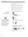
10. Place a strip of black butyl rubber adhesive or
an equivalent over all holes. If using a liquid
construction adhesive, apply bead to mounting
plate in a zig-zag pattern.
11. Reposition mounting plate over tape/adhesive
and attach using 3⁄16”-diameter rivets (or
appropriate fasteners). Seal all rivet heads and
edges with silicone.
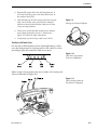
12. Drill cable access hole(s) in vehicle.
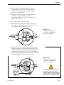
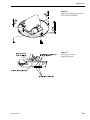
13. When unit is installed with connectors facing the
rear of the vehicle, the factory-drilled drain holes
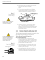
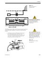
are located as shown in Figure 2-6a.
Figure 2-6a
Connectors Facing Rear
of Vehicle – Factory-drilled
Drain Hole Locations
Front of
Factory-drilled
Vehicle
3/16ý Drain Hole
Positions
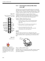
13a.(Alternate Drain Hole Locations) If the antenna unit is
installed with the connectors facing the front of the
vehicle, drill out 3⁄16”-drain holes in rear-facing side of
baseplate as illustrated in Figure 2-6b. The existing
factory-drilled drain holes shown in Figure 2-6a must
then be plugged with silicone rubber sealant.
Angle of Hole, relative to front
Figure 2-6b
Connectors Facing Front
of Vehicle – Recommended
Drain Hole Locations
Front of
Recommended
Vehicle
3/16ý Drain Hole
Positions
Drain Hole Angle
(relative to baseplate)
Angle of Hole, relative to front
54-0149 Rev. B
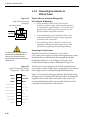
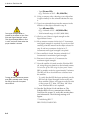
You MUST drill out the drain holes
as indicated to ensure that any
moisture that enters the baseplate
is able to drain. Ensure that factorydrilled holes are completely sealed.
2-5