1
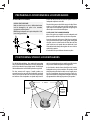
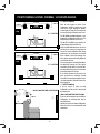
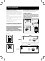
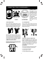
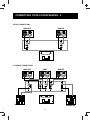
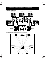
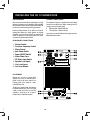
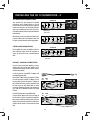
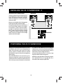
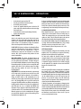
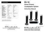
VARDUS
Loudspeaker Systems
Instruction Manual
BRITAIN'S MOST FAMOUS LOUDSPEAKERS
IMPORTANT SAFETY INFORMATION
Unplug this apparatus during lightning storms or when unused for long
periods of time.
CAUTION!
RISK OF ELECTRIC SHOCK
DO NOT OPEN
Refer all servicing to qualified service personnel. Servicing is required
when the apparatus has been damaged in any way, such as powersupply cord or plug is damaged, liquid has been spilled or objects have
fallen into the apparatus, the apparatus has been exposed to rain or
moisture, does not operate normally, or has been dropped.
TO REDUCE THE RISK OF ELECTRIC SHOCK
DO NOT REMOVE COVER (OR BACK)
NO USER-REMOVEABLE PARTS INSIDE
REFER SERVICING TO QUALIFIED PERSONNEL
ADVERTISSEMENT: RISQUE DE CHOC ELECTRIQUENE PAS OUVRIR
Warning: To reduce the risk of fire or electrical shock, do not expose this
product to rain or moisture. The product must not be exposed to dripping
and splashing and no object filled with liquids such as a vase of flowers
should be placed on the product.
This symbol indicates that there are important
operating and maintenance instructions in the
literature accompanying this unit.
No naked flame sources such as candles should be placed on the
product.
This symbol indicates that dangerous voltage
constituting a risk of electric shock is present
within this unit.
Caution: Changes or modifications not expressly approved by the
manufacturer could void the user's authority to operate this device.
Warning: The mains power switch for this appliance is located on the
rear panel. To permit free access to this switch, the apparatus must be
located in an open area without any obstructions.
Read these instructions.
Keep these instructions.
Heed all warnings.
Follow all instructions.
Do not use this apparatus near water.
Clean only with dry cloth.
Do not block any ventilation openings.
Install in accordance with the manufacturer's instructions.
Do not install near any heat sources such as radiators, heat registers,
stoves, or other apparatus (including amplifiers) that produce heat.
ESSENTIAL INFORMATION FOR UK USERS
The power cord on your subwoofer may be supplied with a plug
incorporating a fuse, the value of which is indicated on the pin face of
the plug. Should the fuse need to be replaced, an ASTA or BSI approved
BS1362 fuse must be used of the same rating. If the plug is cut off it
must NOT be re-used. Dispose of any such plug safely. There is a danger
of electric shock if a cut-off plug is inserted into a mains socket.
The wires in the mains lead are coloured in accordance with the
following code: Blue - Neutral: Brown - Live.
As the colours of the wires in the mains lead may not correspond with
the markings identifying the terminals in the replacement mains plug,
proceed as follows:
The wire coloured Blue
must be connected to the
FUSE
terminal marked with the
BS
1362
letter ‘N’ or coloured
Black. The wire coloured
BLUE
BROWN
Brown must be connected
(Live)
to the terminal marked (Neutral)
with the letter ‘L’ or
coloured Red.
Do not defeat the safety purpose of the polarized or grounding type
plug. A polarized plug has two blades with one wider than the other. A
grounding type plug has two blades and a third grounding prong. The
wider blade or the third prong are provided for your safety. If the
provided plug does not fit into your outlet, consult an electrician for
replacement of the obsolete outlet.
Protect the power cord from being walked on or pinched, particularly at
plugs, convenience receptacles, and the point where they exit from the
apparatus.
Use only attachments/accessories specified by the manufacturer.
Use only with a cart, stand, tripod, bracket, or
table specified by the manufacturer, or sold with
the apparatus. When a cart is used, use caution
when moving the cart/ apparatus combination to
avoid injury from tip-over.
Class II construction double insulated.
This product must not be connected to earth.
2
PRELIMINARIES
UNPACKING YOUR LOUDSPEAKERS
After taking out the top packing piece, lift the loudspeakers
and accessories from the carton. Remove all the protective
bags. Do NOT lift the loudspeakers out using the bags.
Accessories provided with each loudspeaker are as follows:
VR-200, 300, 400
! One set of spikes with mounting hardware.
! One set of rubber feet
VR-50, 100
! One set of rubber feet
VR-CEN 1, CEN 2
! No accessories needed
VR-SURR 1, SURR 2
! No accessories needed
VR-10 SUB
! Four floor spikes (attached to the subwoofer)
! IEC power cord suitable for your location
Check all items after unpacking. If any item is missing or
damaged, immediately contact your Wharfedale dealer.
Retain the packaging. If you dispose of the packing, follow
all recycling regulations in your area.
Before installing this product
read all these instructions!
Before making any connections, switch all the units in
your system off at the mains.
Set the volume control at minimum when you switch on
your system or change sources, and turn the level up
gradually.
DO NOT use your amplifier at full volume.
Ensure that all loudspeakers in the system are correctly
wired.
DO NOT subject your loudspeakers to excessive cold, heat,
humidity or sunlight.
DO NOT place heavy objects on top of loudspeakers
DO NOT connect speaker terminals to the mains supply.
DO NOT dismantle the loudspeaker. There are no user
serviceable parts inside it and you will void the warranty.
PREPARATIONS
FOR
INSTALLATION
PREPARATION
PREPARATIONS
FOR
FOR
INSTALLATION
INSTALLATION
CONNECTORS AND CABLES
Before connecting your system consider where you will place the
speakers in the room. This is particularly important if you are
wall mounting the centre or surround loudspeakers.
Stereo systems require two lengths of two core cable. 5.1 and
7.1 installations require 5 and 7 lengths respectively.The cables
connecting the Front loudspeakers should be the same length
and the cables connecting the Surround (and Rear) speakers
should also be of equal length. We suggest you use audio cable
and not general purpose ‘bell’ or ‘zip’ wire.
VR-50, 100: These loudspeakers are designed to be
mounted on a rigid floor stand. The loudspeaker may also be
placed on a sturdy shelf or wall mounted on a suitable wall
bracket. Consult your dealer for advice if you are in any doubt.
VR-10 SUBWOOFER:
VR-200, 300, 400: These are floorstanding models. For
improved performance the loudspeakers are spike coupled to
the floor. Rubber feet are provided as an alternative.
Ensure there is a mains point within easy reach of the unit.
You will need to purchase a suitable RCA interconnect cable to
connect the subwoofer to your pre-amplifier or A/V amplifier
(see page11). This cable must be a high quality fully screened
cable. Poorly screened cable is liable to pick up stray hum and
interference fields and should be avoided.
CAUTION: When running cables to loudspeakers, do not trail
them across open floors where they can be a source of danger.
Route them safely, around room boundaries if necessary.
VR-CEN, CEN 2; VR-SURR 1, SURR 2: The centre
and surround loudspeakers are intended to be operated
attached to the wall via keyhole mounts in the rear of the
loudspeaker (see Page 6). Fixings for attaching the
loudspeakers to the wall are not supplied.
3
PREPARING FLOORSTANDING LOUDSPEAKERS
ATTACHING THE SPIKES
Place a soft cloth on the floor to protect the speaker. Invert the
loudspeaker and place it on the cloth.
CAUTION: SPIKES ARE SHARP.
Make sure that there are no wires or hidden obstacles that
could be damaged by the spikes in the immediate
operational area of the speakers.
NEVER drag a loudspeaker on its spikes. Always lift it. If the
item is heavy get assistance.
Thread a locking nut two-thirds of the way up the spike. Place a
washer over the spike and insert each spike assembly into a
spike mount on the loudspeaker. Tighten the nut finger tight so
that the spike is secure but not locked in place.
LEVELLING THE LOUDSPEAKER
After all the spikes are attached, invert the loudspeaker and
place it carefully on the floor. Place a spirit level on the speaker
Loosen the nut on each spike one turn. If the floor is not perfectly
level you will find that one spike is off the ground. Starting with
this spike, unscrew it so that it touches the floor. Move the other
spikes in and out so the speaker does not wobble and is level
front and back and sideways. Now tighten the nuts to lock the
spikes firmly in position
A set of rubber feet is provided as an alternative to spikes.
POSITIONING STEREO LOUDSPEAKERS
The VR-200, 300, and 400 are floor standing. We suggest that
they are positioned at least 200 mm from the rear walls and 700
mm from the side walls, facing slightly inwards. The VR-50 and
100 should be stand or wall mounted or placed on a rigid shelf.
walls, the inward angle may be increased by up to 40%, but this
may restrict the width of the optimum listening position.
A rule of thumb is that the listener should be as far from the
loudspeakers as they are from each other. The speakers should
ideally be positioned so that the treble units are roughly at ear
level to a seated listener. As personal taste plays a large role,
experiment with different configurations and play a wide range
of programme before finalising the position of your speakers.
The bass extension will improve if smaller speakers are
operated closer to the rear walls. If the loudspeakers are placed
too close to the walls the bass will increase but may be boomy
and indistinct. If the loudspeakers are placed away from the
>0.7metre
40
º
2 - 4 metres
VR-200-400
>200 mm
VR-50, 100
>50 mm
15 -
4
POSITIONING HOME CINEMA LOUDSPEAKERS
5.1 POSITIONING
2-4 metres
>200 mm
>150 mm
CENTRE
SUB
5.1 SYSTEM
Place the front speakers as shown. Front
loudspeakers should be placed away from
walls for best results. Angling the speakers
inward slightly will improve stereo images but
too extreme an angle will impair movie sound.
The VR-100 200 and 300 loudspeakers must
be placed at least 450mm from a TV screen. The
VR-50 may be operated close to a TV screen.
The VR-CEN 1 and CEN 2 centre speakers can
be placed above or below the TV screen.
2-4 metres
>200 mm
>150 mm
CENTRE
SUB
7.1 SYSTEM
Place the VR-10 SUB subwoofer as close to the
wall as you can, leaving just enough space to
operate the controls and mains switch. Room
positioning is not critical but we recommend
that it is placed in front of the listening seat.
Never operate the subwoofer within 450mm of
a conventional TV screen.
The surround speakers should be placed above
and behind the listening seat. They may be
mounted on the side walls or on the rear walls
but always behind the listener. Do not operate
them within 450mm of a TV screen.
If the distance between the side walls is too
great, you could use a second pair of stand
mounted or floorstanding loudspeakers as the
surround loudspeakers, placed as shown in the
drawing opposite.
7.1 POSITIONING
WALL MOUNTING POSITIONS
If you are using a 7.1 system, the back
loudspeakers must be at least 1 metre behind
the listening seat.
WALL MOUNTING POSITIONS
If you are wall mounting the centre and effects
loudspeakers we recommend that they be
mounted as shown.
400 mm
1m
Wall mounting the centre channel loudspeaker
below the screen is not recommended for fixed
installations.
5
WALL MOUNTING
The Satellite and Centre loudspeakers are provided with
integral keyhole mounts for wall mounting.
Wall mounting should be carried out by licensed sound contractors or
technicians with appropriate qualifications and experience. All
installation and wiring should comply with the relevant standards laid
down by the competent authority in the country and place of
installation.
Before you attempt wall or ceiling mounting, ensure the surface
is stable and strong enough to support the weight of the speaker
and mounting hardware.
Determine the location of the loudspeakers. Identify your
loudspeaker from the drawings on this page.
heads and carefully lower the unit onto the screws.
Remove the loudspeakers from the wall ready for connection.
After connection they can be re-installed on the wall.
VR-SURR 1; VR-SURR 2
You will need one No.8 screw and a matching wall plug per
speaker. Proceed as outlined above and attach each
loudspeaker to the wall via the single keyhole slot integrated
into the crossover connection panel.
b
6.0mm
d
No 8 x 40mm
c
VR-CEN 1; VR- CEN 2
You will need 2 No.8 screws and matching wall plugs to attach
each loudspeaker to the wall. These are the responsibility of the
installer who should supply suitable fixings for this purpose.
Mark off a horizontal line on the wall. Use a spirit level to ensure
that the line is accurately drawn. Mark off two points on this line
at the mounting centres indicated in the drawings.
Drill two 6mm holes in the wall at the points marked. Fix a
suitable No 8 round head screw firmly into each hole using
appropriate wall plugs. Leave a stub of 5mm protruding from
the wall. Align the holes in the mounting brackets over the screw
e
5mm
VR-SURR 1
310mm
VR-CEN 1
VR-SURR 2
360mm
VR-CEN 2
_
6
+
CONNECTING YOUR LOUDSPEAKERS - 1
TERMINAL PANELS
-
All the loudspeakers connect to
the amplifier via a twin
terminal connecting panel. The
positive terminal is located at
the right of the panel and is
coded Red, The Negative
terminal is coded Black.
-
VR-SURR 1
The VR-SURR 1 uses spring
loaded push terminals. All the
other models use screw
terminals.
ALL OTHER MODELS
VR-SURR 2
CABLE PREPARATION
ALL OTHER MODELS
Prepare a suitable length of loudspeaker cable for each unit.
Split the twin cores to a depth of about 40mm. Carefully strip the
insulation from each end, leaving about 8mm of bare wire. If
the cable is stranded, lightly twist to gather any loose strands.
Unscrew a terminal. Thread the bared end of each cable
through the hole in the bottom of the terminal post. Ensure that
there are no loose strands which may touch adjacent terminals.
Retighten the terminal securely.
8mm
b c
40mm
Audio cable is polarised, with two cores of different colours, or
often a coloured tracer or identification rib. We suggest that you
connect the coloured/striped wire to the RED, Postive terminals
of your AV amplifier. This will ensure that all the loudspeakers
are connected the correct way round and avoid set-up problems.
AMPLIFIER - SPEAKER CONNECTIONS
Connect each loudspeaker to the correct channel of your
amplifier or AV processor taking care to connect the Red,
Positive (+) terminal of the speaker to the Red, Positive (+)
terminal of the speaker output terminal of the amplifier, and
similarly with the Black, Negative (–) terminal. Use the
connection diagrams on the next page to help you.
CONNECTING THE VR-SURR 1
Press down on a terminal lever. Insert the wire into the terminal.
Release the lever. Ensure that the terminal grips the bare wire at
the end of the cable, not the insulation.
WALL MOUNTING
If you are wall mounting speakers please follow this procedure.
1: Run the cable from the amplifier to the speaker location.
2: Connect the cable to the loudspeaker.
3: Hang the loudspeaker on the wall.
4: Connect the loudspeaker cable to the amplifier.
7
CONNECTING YOUR LOUDSPEAKERS - 2
STEREO CONNECTIONS
FRONT RIGHT
FRONT LEFT
L
R
ROOM PLACEMENT
5 CHANNEL CONNECTIONS
FRONT RIGHT
R
CENTRE
C
R
FRONT LEFT
L
L
ROOM PLACEMENT
SURROUND RIGHT
SURROUND LEFT
8
7 CHANNEL CONNECTIONS & PLACEMENTS
7 CHANNEL CONNECTIONS
FRONT RIGHT
R
SURROUND RIGHT
CENTRE
R
C
R
FRONT LEFT
L
L
L
SURROUND LEFT
ROOM PLACEMENT
BACK RIGHT
BACK LEFT
Dolby Labs Recommended 7.1 Placement (Single Back channel for 6.1 shown dotted)
Centre
Left Front
LFE
22º
Right Front
30º
Left Surround
Right Surround
90º
110º
135º
150º
Left Back
Right Back
9
INSTALLING THE VR 10 SUBWOOFER
PRELIMINARIES
POWER CONNECTIONS
Open the carton and remove all the top packing pieces. Lift the
subwoofer out taking care not to damage the cabinet. DO NOT
lift the subwoofer out of the carton using the protective bag. The
unit is heavy; if you cannot manage it easily, get assistance.
This subwoofer is factory set to operate from the mains voltage
marked on the amplifier panel. Before connecting check this
voltage is correct for your mains supply.
230 volt products - 220 volts to 240 volts
115 volt products - 110 volts to 120 volts
!
!
Retain the packing materials. If you decide not to keep the
packing, please dispose of it having regard to any recycling
regulations in your area. Please retain the user manual. If you
transfer this equipment to a third party, please ensure all the
instructions are passed on with the product.
If you move to an area with a different mains supply, consult your
Wharfedale dealer for advice.
REAR PANEL CONNECTIONS
b Volume Control
c
d
e
f
g
h
i
j
1)
Crossover Frequency Control
Phase Control
Auto Power Switch
Power ON/OFF Switch
Mains Power Fuse
IEC Mains Input Socket
Speaker Level Inputs
Line Level Inputs
Line Level Outputs
LINE LEVEL
INPUT
OUTPUT
CROSSOVER
CROSSOVER
FREQUENCY
FREQUENCY
VOLUME
55
LEFT
65
45
PHASE
75
35
RIGHT
180º
ON
OFF
AUTO
POWER
(Hz)
VOLUME
SPEAKER LEVEL INPUTS
0º
85
CROSSOVER
FREQUENCY
SUB-WOOFER AMPLIFIER
WHARFEDALE INTERNATIONAL HUNTINGDON, UNITED KINGDOM
SERIAL No.:
RIGHT
LEFT
N
11189
PLACEMENT
Although the unit may be placed almost
anywhere in the room, we recommend that is
placed in front of the listener central to the
listening position. There should be a mains
outlet within easy reach.
The bass port is mounted under the subwoofer
firing downward and moves a lot of air at high
volume, so make sure the floor is sound. The
subwoofer is front-firing so do not place it
behind surfaces or objects that may rattle.
WARNING:
TO REDUCE THE RISK OF FIRE OR ELECTRICAL SHOCK
DO NOT EXPOSE THIS PRODUCT TO RAIN OR MOISTURE
FUSE
T2A 250V
AC INPUT
FUSE
POWER
O
OFF
~230V/50Hz 150W
CAUTION:
DISCONNECT SUPPLY CORD
BEFORE CHANGING FUSE.
REPLACE ONLY WITH SAME
TYPE FUSE AND RATING
10
ON
ATTENTION:
REPLACER LE FUSIBLE.
UTILISER UN FUSIBLE DE
RECHANGE DE MEME TYPE
ET CALIBRE
!
INSTALLING THE VR 10 SUBWOOFER - 2
A/V PROCESSOR CONNECTIONS
AV AMPLIFIER
Your subwoofer has been designed for optimum
performance with a Digital processor. If your AV
processor has a line level or LFE subwoofer output you
should use this connection. You will need to purchase a
single screened RCA phono lead from your dealer.
Connect this lead to the Left line input of the Subwoofer
as shown below
RIGHT
LEFT
CENTRE
LEFT
FRONT
Subwoofer Out
(Line Level)
Alternatively, you may use a split mono lead from the
processor to both inputs of the subwoofer. In this case
the input level at the subwoofer will be slightly higher.
RIGHT
LEFT
REAR
STEREO LINE CONNECTIONS
If your amplifier has a spare preamplifier output or a
stereo sub-woofer output, connect the sub-woofer as
shown. You will need a stereo screened RCA phono
cable.
RIGHT
REAR
RIGHT
CENTRE
LEFT
FRONT
AV AMPLIFIER
L
R
RIGHT
LEFT
REAR
RIGHT
CENTRE
LEFT
FRONT
Subwoofer or Pre Out
(Line Level)
PRE OUT - MAIN IN CONNECTIONS
If you use a stereo pre and power amplifier, or a stereo
amplifier where the pre and main amplifier can be
separated, connect the sub-woofer as shown. There are
two alternative methods.
A: You will need two screened RCA ‘Y’ adaptors and
two single RCA phono cables.
Remove the Pre-Main links on your amplifier. Connect
the socket (common) of an RCA ‘Y’ adaptor to one of
the mono cables. Connect one leg of the ‘Y’ adaptor to
the Left Channel Pre Out socket on the amplifier and
the other leg to the Left Channel Main In socket.
Connect the remaining plug to the Left Channel Line
Level Input on the subwoofer. Repeat for the Right
Channel.
B: You will need two stereo screened RCA cables.
Connect a Stereo cable from the Line Level Inputs of
the sub-woofer to the Pre Out sockets of the amplifier.
Now connect a second Stereo cable from the Line Level
Outputs of the sub-woofer to the Main In sockets of the
amplifier. The sub-woofer is now inserted in the system
loop.
(x2)
PRE
OUT
MAIN
IN
L
AMPLIFIER
R
PRE
OUT
RIGHT
LEFT
RIGHT
LEFT
MAIN
IN
L
AMPLIFIER
R
11
INSTALLING THE VR 10 SUBWOOFER - 3
SPEAKER LEVEL CONNECTIONS
FRONT RIGHT
FRONT LEFT
RIGHT
LEFT
The high level Speaker connections should be used only
if your amplifier does not have a line level subwoofer
output. In this connection the subwoofer is fed together
with the Front loudspeakers. For this you will need two
extra twin core cables.
Measure out two loudspeaker cables of the appropriate
length. Prepare the cables as described on Page 7.
Connect the Left Speaker Terminals on the sub bass unit
to the Front Left speaker terminals on the amplifier.
Connect the Red (+) speaker terminal on the amplifier
to the Red (+) terminal on the subwoofer. Connect the
Black (-) speaker terminal on the amplifier to the Black
(-) terminal on the subwoofer. Now connect the Right
Speaker terminals on the subwoofer to the Front Right
speaker terminals of the amplifier.
SPEAKER LEVEL INPUTS
SUBWOOFER
LEFT
RIGHT
POSITIONING THE VR-10 SUBWOOFER
Although the unit may be placed almost anywhere in the room,
even behind the sofa or the TV set, we recommend that it be
placed in front of the listener and as central to the listening
position as possible. The subwoofer should not be operated
within 450mm of a television set as the drive unit magnet may
distort the picture.
to a distance of about 200mm from the wall. Placing the
subwoofer across a room corner will increase the bass further,
possibly at the expense of clarity. Experiment with a variety of
locations and sources before making a final decision.
Place the VR-SUB subwoofer as close to the wall as you can,
leaving just enough space to operate the controls and mains
switch. A position close to the wall will enhance the bass; If the
bass is excessive you can move the subwoofer out from the wall
NOTE: When running signal cables to the subwoofer, keep them
clear of obstructions. Do not run a long signal cable close to
mains cables or cables carrying heavy digital traffic.
Your system will perform best if there is a clear line of sight
between the subwoofer and the listening position.
12
VR 10 SUBWOOFER - OPERATION
SETTING UP
!
!
!
!
!
!
HOME THEATRE TOPICS
Set the subwoofer power switch to OFF.
Turn the system Volume Control to minimum.
Re-check all system connections.
Connect the supplied subwoofer power lead to the IEC
power socket on the subwoofer and connect the mains plug
into the wall socket.
Set the subwoofer volume control midway (12o'clock)
Switch on the mains power.
As the ear is unable to detect the direction from which deep bass
originates, this allows freedom in positioning the subwoofer.
Varying the distance from the wall alters the amount of bass.
Some prefer to place the subwoofer against a room corner. This
arrangement gives more bass at the possible expense of clarity.
LOUDSPEAKER SIZES
Many digital AV processors require you to specify the size of
speakers in the various channels. These are usually ‘Large’ or
‘Small’. We recommend that you set the centre and surround
speakers to 'Small'. This will direct all the bass in the system to
the subwoofer and provide clean, deep and louder bass.
FINE TUNING
Switch on the subwoofer power switch. Check that the power
indicator on the front of the cabinet glows. Now switch on the
system. Play a programme with extended bass and set the
system volume to a reasonable level. Adjust the subwoofer
volume control to produce the desired level of bass.
Set the VR-50, 100 and 200 to “Small” The VR-400 should be set
to “Large”. We recommend the VR-300 be set to “Large” though
if the bass is excessive, you may wish to set it to “Small”.
Set the ‘Subwoofer’ option on the processor to 'On’ or 'Yes'.
PHASE SWITCH: If the bass is indistinct or lacks depth, the Phase
switch may need adjustment. Set the switch to 0º and listen
carefully to some music with extended bass. If there is
insufficient bass output from the sub-woofer set the Phase
switch to 180º. Select the position which produces the most
natural, extended bass.
SETTING LEVELS
Once the loudspeaker settings have been finalised, put the AV
amplifier into its “Test” mode (see your processor instructions),
Adjust the levels until all channels are equally loud.
You may need to adjust the subwoofer output level. Avoid
setting too high a level or you will swamp the sound with bass
which be tiring to listen to and may limit the subwoofer’s ability
to respond to large bass transients. Set a sensible level going
into the subwoofer. The subwoofer volume control should be
between 12 o’clock and 3 o’clock .
LOW PASS FILTER. This adjusts the blend between the
subwoofer and the main speakers. and enables the system to be
set up for optimum bass performance. The higher settings are
for use with bookshelf loudspeakers, the lower settings for large
floorstanding models. If you choose too low a setting with small
speakers, there will be a ‘hole’ in the bass response; too high a
setting with large speakers will result in the upper bass
becoming bloated.
LFE
AUTO SWITCH. In normal mode the subwoofer is permanently
on. This may result in low level hum or noise if the rest of the
system is switched off and the subwoofer is left switched on.
Setting the AUTO switch to ON automatically turns the
subwoofer on when a signal is detected at any of the inputs and
turns it off (Standby Mode) after a period of inactivity. We
recommend the AUTO switch be set to ON for normal operation.
The Low Frequency Effects channel was designed as an additional
bass channel with its own dedicated subwoofer. In practice
however, if all the speakers are set to Small, the LFE channel will
be combined with the bass from other channels and all this feeds
into the subwoofer. When you set the LFE level from your AV
processor, use care with this setting as the LFE channel may
contain powerful low frequencies which, although normal in a
cinema, may overload a domestic subwoofer.
In AUTO mode the indicator on the front of the subwoofer will
glow RED when the unit is in Standby and GREEN when
operational. If your subwoofer is disconnected from the mains
or the Power switch is “Off”, the indicator will be extinguished.
If, during a programme, you hear popping or thumping noises
coming from the subwoofer, immediately turn the AV Processor's
volume level down and then back off the LFE level. If this does not
cure the problem, back off the volume level at the subwoofer.
When the system is not in use for extended periods, we suggest
you switch off the subwoofer to protect it from switching noises
caused by domestic appliances, etc.
Please read the relevant sections of your AV amplifier manual
and familiarise yourself with the various issues. If you are
unsure, consult your dealer for help.
13
FURTHER INFORMATION
TROUBLESHOOTING - Before investigating a problem, always switch off the system at the mains.
If your system is not working properly please work through this checklist before returning a unit to your dealer.
Symptom
Possible Cause
No Sound
System not switched on; Speaker cables shorting terminals out; Wrong source selected
Sound lacks bass content
Bass reproduction indistinct
Front loudspeakers out of phase. Check all system connections and rectify.
Subwoofer not switched on; Subwoofer phase incorrect; Subwoofer crossover control too low
Excessive bass distortion at low volumes Subwoofer level set too high; LFE level set too high; Subwoofer incorrectly wired
Excessive or distorted bass at high levels System level set too high; Bass control set too high; Speakers too close to room corners
Distorted / rattling sounds at high levels System level too high; Objects on speakers/subwoofer; Objects too close to subwoofer
Popping or thumping from the subwoofer System level set high; Subwoofer level set too high; LFE level set too high
Indistinct sound; Poor localisation of
effects. Poor localisation of dialogue
One or more loudspeakers is out of phase. Check all system connections and rectify.
(Read the manual for correct connection procedure)
Television picture colour is distorted
Subwoofer too close to TV. (Switch off system and TV. Move units away. Leave 15 mins. Switch on.
SPECIFICATIONS
Stand/Bookshelf
Loudspeakers
VR-50
VR-100
Format
Bass unit
Tweeter
Rec. Amplifier Power
Nominal Impedance
A/V shielding
Sensitivity (1W @ 1M)
Freq. Response (-6dB)
Cabinet Volume
Size (H x W x D)
Stand: Ported
125mm
25mm
10 -100 W
6 Ohms
Yes
86 dB
65 Hz-20kHz
6.2 Litres
296 x 194 x 200 mm
Stand: Ported
150mm
25mm
10 -100 W
6 Ohms
No
87 dB
60 Hz-20kHz
10 Litres
365 x 223 x 220 mm
14
SPECIFICATIONS
Front Loudspeakers
VR-200
VR-300
VR-400
Format
ABR/Bass Unit
Bass unit
Bass mid unit
Tweeter
Rec. Amplifier Power
Nominal Impedance
A/V shielding
Sensitivity (1W @ 1M)
Freq. Response (-6dB)
Cabinet Volume
Size (H x W x D)
Size with feet (H x W)
Tower: Ported
Tower: Ported
Tower: Ported
150mm
150mm
150mm
25mm
10 -150 W
6 Ohms
No
90 dB
40 Hz-20kHz
29.8 Litres
920 x 223 x 255 mm
960 x 267 mm
150mm
150mm
25mm
25mm
10 -120 W
10 -100 W
6 Ohms
6 Ohms
No
No
88 dB
88 dB
50 Hz-20kHz
55 Hz-20kHz
27.8 Litres
25.8 Litre
800 x 223 x 255 mm 860 x 223 x 255 mm
900 x 267 mm
840 x 267 mm
150mm
Effects Loudspeakers VR-CEN 1
VR-CEN 2
VR-SURR 1
VR-SURR 2
Centre; Ported
2 x 125 mm
25 mm
10 -150 W
6 Ohms
Yes
90 dB
70 Hz - 20 kHz
5.5 Litres
168 x 436 x 150 mm
Surround; Ported
75 mm
22 mm
10 -100 W
6 Ohms
No
87 dB
110 Hz - 20 kHz
1.25 Litres
150 x 115 x 110 mm
Surround; Ported
125 mm
25 mm
10 -100 W
6 Ohms
No
86 dB
80 Hz - 20 kHz
3.2 Litres
296 x 194 x 115 mm
Format
Bass/Bass mid unit
Tweeter
Rec. Amplifier Power
Nominal Impedance
A/V shielding
Sensitivity (1W @ 1M)
Freq. Response (-6dB)
Cabinet Volume
Size (H x W x D)
Centre; Ported
2 x 100 mm
25 mm
10 -100 W
6 Ohms
Yes
89 dB
80 Hz - 20 kHz
4.6 Litres
148 x 385 x 130 mm
Subwoofer
VR-10 SUB
Format
Bass Woofer
A/V shielding
Amplifier Power
Input Sensitivity
Avg. Max Output at 1 metre
Freq. Response (boundary pos)
Crossover Range
Cabinet Volume
Size inc feet (H x W x D)
Reflex
250 mm
No
150 Watts
300 mV at 100 W output
110dB
35 Hz - 110 Hz
35 - 85 Hz
31 Litres
340 x 350 x380 mm
15
SERVICE AND WARRANTY
CARE AND MAINTENANCE
AUTHORISED SERVICE CENTRES
If you play the speakers with the grilles off exercise great care.
NEVER touch the drive units which are easily damaged.
The loudspeaker cabinets can be cleaned with a damp cloth or
with a spray furniture polish and a soft cloth. Apply the spray
sparingly to the cloth and then polish the cabinet. Never apply
spray directly to the cabinet.
UK
Wharfedale International Ltd. IAG House, Sovereign Court,
Ermine Business Park, Huntingdon, Cambs PE29 6XU, England.
Tel:+44 (0)1480 447700 Fax: +44 (0)1480 43176
GUARANTEE & SERVICE
In the unlikely event that your unit develops a fault you should
return it to your Wharfedale dealer using the original packing
to ensure safe shipping.
The terms of your guarantee may vary in different countries but
in all cases the guarantee excludes:
All damage caused through accident, misuse, wear and tear,
neglect, incorrect installation, adjustment or repair by
unauthorised personnel. Liability for damage or loss occurring
in transit to or from the purchaser.
Wharfedale will not be liable for any consequential damage,
loss or injury, arising from or in conjunction with this
equipment.
ASIA
IAG. Room 2310 - 2311, Press Building, Shennan Road C,
Shenzhen, China.
Tel: +86-755-82091200 Fax: +86-755-82091205
USA
IAG America, Inc. 8440 154th Avenue NE, Redmond, Washington
98052 USA
Tel: +1 425 861 3909 Fax: +1 425 861 390
For information on other authorised service centres worldwide contact
Wharfedale International in the U.K.
A worldwide distributor list is available on the Wharfedale website:
www.wharfedale.co.uk
Wharfedale has a policy of continuous product development and
reserves the right to change specification without notice.
The name ‘WHARFEDALE' is a registered trademark of Wharfedale
International Ltd. Wharfedale is a member of the International
Audio Group
Wharfedale International Ltd., IAG House, Sovereign Court, Ermine Business Park, Huntingdon, Cambs PE29 6XU, England.
Tel:+44 (0)1480 447700 www.wharfedale.co.uk
Wharfedale is a member of the International Audio Group.