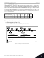
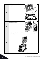
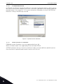
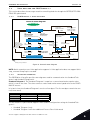
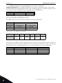
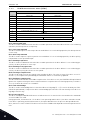
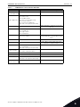
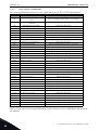
1
vacon
ac drives
profibus dp option board opte3/E5
user manual
®
vacon • 1
TABLE OF CONTENTS
Document: DPD00997B
Order code: DOC-INS06834+DLUK
Release date : 3.10.2014
1.
Safety................................................................................................................3
1.1
1.2
1.3
1.4
1.5
Danger.................................................................................................................................3
Warnings .............................................................................................................................4
Earthing and earth fault protection ....................................................................................5
Electro-magnetic compatibility (EMC)................................................................................6
Compability with RCDs........................................................................................................6
2.
3.
PROFIBUS DP - general ....................................................................................7
PROFIBUS DP technical data.............................................................................8
3.1
3.2
General................................................................................................................................8
PROFIBUS DP cable............................................................................................................9
4.
Layout, connections and installation...............................................................10
4.1
4.2
4.3
4.4
4.5
4.5.1
4.5.2
4.6
4.6.1
4.6.2
4.7
4.8
PROFIBUS OPTE3/E5 option board layout........................................................................10
Connections.......................................................................................................................10
LED indications .................................................................................................................11
Jumpers ............................................................................................................................12
Installation in Vacon® 100...............................................................................................13
Prepare for use through fieldbus .....................................................................................15
Finishing the cabling.........................................................................................................20
Installation in Vacon® 20..................................................................................................22
Frames MI1, MI2, MI3 .......................................................................................................22
Frames MI4, MI5 ...............................................................................................................25
Installation in Vacon® 20 X and 20 CP .............................................................................29
Installation in Vacon® 100 X (Frames MM4-MM6) ..........................................................33
5.
Commissioning ...............................................................................................37
5.1
5.1.1
5.2
5.2.1
5.3
5.3.1
5.3.2
5.3.3
PROFIBUS DP board parameters .....................................................................................37
Parameter descriptions ....................................................................................................37
PROFIBUS DP board monitor values................................................................................40
Monitor value descriptions ...............................................................................................40
Replacing NX with V100 ....................................................................................................41
Fieldbus configuration (GSD) file......................................................................................41
Parameterization ..............................................................................................................42
Other issues to consider ...................................................................................................42
6.
PROFIBUS DP interface...................................................................................43
6.1
6.2
6.2.1
6.2.2
6.2.3
6.2.4
6.2.5
6.2.6
6.2.7
6.2.8
6.2.9
6.3
6.3.1
6.3.2
6.3.3
6.3.4
6.3.5
General..............................................................................................................................43
Data mapping for PROFIdrive 4.1 .....................................................................................45
PROFIdrive 4.1 state machine ..........................................................................................45
Standard telegrams ..........................................................................................................45
PROFIdrive Control word (STW1)......................................................................................48
PROFIdrive Status word (ZSW1) .......................................................................................49
Setpoint value....................................................................................................................50
Actual speed value ............................................................................................................51
Normalization reference parameter ................................................................................51
Shortlist of commands to start the drive..........................................................................52
Coding of data signals.......................................................................................................53
Parameter Access in PROFIdrive 4.1................................................................................54
Parameter Access sequence ............................................................................................54
Parameter requests..........................................................................................................55
Parameter responses .......................................................................................................57
Example requests and responses ....................................................................................67
Supported parameters......................................................................................................72
24-hour support +358 (0)201 212 575 • Email: [email protected]
vacon • 2
6.4
6.4.1
6.4.2
6.5
6.5.1
6.5.2
6.5.3
6.6
6.6.1
6.6.2
6.6.3
6.7
Data mapping for PROFIdrive 2.0 .....................................................................................73
State machine for PROFIdrive 2.0.....................................................................................74
PPO types ..........................................................................................................................74
Parameter Access in PROFIdrive 2.0................................................................................76
DP-V1 with PROFIdrive 2.0 ...............................................................................................76
Parameter field (PKW) in PPO types ................................................................................76
Examples...........................................................................................................................78
Data Mapping in Bypass operate mode ............................................................................80
Bypass control word .........................................................................................................80
Bypass status word...........................................................................................................80
Bypass setpoint and actual value .....................................................................................80
Data Mapping in Echo operating mode.............................................................................81
Tel. +358 (0) 201 2121 • Fax +358 (0)201 212 205
Safety
vacon • 3
1.
SAFETY
This manual contains clearly marked cautions and warnings which are intended for your personal
safety and to avoid any unintentional damage to the product or connected appliances.
Please read the information included in cautions and warnings carefully.
The cautions and warnings are marked as follows:
Table 1. Warning signs
= DANGER! Dangerous voltage
9000.emf
= WARNING or CAUTION
13006.emf
= Caution! Hot surface
9001.emf
1.1
9000.emf
9000.emf
9000.emf
9000.emf
9000.emf
9000.emf
Danger
The components of the power unit are live when the drive is connected to mains
potential. Coming into contact with this voltage is extremely dangerous and may
cause death or severe injury.
The motor terminals U, V, W and the brake resistor terminals are live when the
AC drive is connected to mains, even if the motor is not running.
After disconnecting the AC drive from the mains, wait 5 minutes before doing any
work on the connections of the drive. Do not open the cover before this time has
expired. After expiration of this time, use a measuring equipment to absolutely
ensure that no voltage is present. Always ensure absence of voltage before starting any electrical work!
The control I/O-terminals are isolated from the mains potential. However, the
relay outputs and other I/O-terminals may have a dangerous control voltage
present even when the AC drive is disconnected from mains.
Before connecting the AC drive to mains make sure that the front and cable covers of the drive are closed.
During a coast stop (see Application Manual), the motor is still generating voltage
to the drive. Therefore, do not touch the components of the AC drive before the
motor has completely stopped. Wait 5 minutes before starting any work on the
drive.
24-hour support +358 (0)201 212 575 • Email: [email protected]
1
vacon • 4
1.2
Safety
Warnings
The AC drive is meant for fixed installations only.
13006.emf
Do not perform any measurements when the AC drive is connected to the mains.
13006.emf
13006.emf
13006.emf
The touch current of the AC drives exceeds 3.5 mA AC. According to standard EN
61800-5-1, a reinforced protective ground connection must be ensured. See
Chapter 1.3.
If the AC drive is used as a part of a machine, the machine manufacturer is
responsible for providing the machine with a supply disconnecting device (EN
60204-1).
Only spare parts delivered by Vacon can be used.
13006.emf
13006.emf
13006.emf
13006.emf
13006.emf
13006.emf
13006.emf
13006.emf
1
At power-up, power brake or fault reset the motor will start immediately if the
start signal is active, unless the pulse control for Start/Stop logic has been selected.
Futhermore, the I/O functionalities (including start inputs) may change if parameters, applications or software are changed. Disconnect, therefore, the motor if
an unexpected start can cause danger.
The motor starts automatically after automatic fault reset if the autoreset function is activated. See the Application Manual for more detailed information.
Prior to measurements on the motor or the motor cable, disconnect the motor
cable from the AC drive.
Do not touch the components on the circuit boards. Static voltage discharge may
damage the components.
Check that the EMC level of the AC drive corresponds to the requirements of your
supply network. See Installation manual.
In a domestic environment, this product may cause radio interference in which
case supplementary mitigation measures may be required.
The AC drives are suitable for use on a circuit capable of delivering not more than
100,000 rms symmetrical amperes, 600 V maximum.
Tel. +358 (0) 201 2121 • Fax +358 (0)201 212 205
Safety
vacon • 5
1.3
Earthing and earth fault protection
CAUTION!
13006.emf
The AC drive must always be earthed with an earthing conductor connected to the earthing terminal
marked with
.
The touch current of the drive exceeds 3.5 mA AC. According to EN 61800-5-1, one or more of the
following conditions for the associated protective circuit shall be satisfied:
A fixed connection and
a) the protective earthing conductor shall have a cross-sectional area of at least 10 mm2 Cu
or 16 mm2 Al.
or
b) an automatic disconnection of the supply in case of discontinuity of the protective earthing
conductor. See Chapter 5.
or
c)
provision of an additional terminal for a second protective earthing conductor of the same
cross-sectional area as the original protective earthing conductor.
Table 2. Protective earthing conductor cross-section
Minimum cross-sectional area of the corCross-sectional area of phase conductors (S)
responding
protective earthing conductor
[mm2]
[mm2]
S ≤ 16
16 < S ≤ 35
35 < S
S
16
S/2
The values above are valid only if the protective earthing conductor is made of the same metal as
the phase conductors. If this is not so, the cross-sectional area of the protective earthing conductor
shall be determined in a manner which produces a conductance equivalent to that which results
from the application of this table.
The cross-sectional area of every protective earthing conductor which does not form a part of the
supply cable or cable enclosure shall, in any case, be not less than
•
•
2.5 mm2 if mechanical protection is provided or
4 mm2 if mechanical protection is not provided. For cord-connected equipment, provisions
shall be made so that the protective earthing conductor in the cord shall, in the case of failure of the strain-relief mechanism, be the last conductor to be interrupted.
However, always follow the local regulations for the minimum size of the protective earthing
conductor.
NOTE: Due to the high capacitive currents present in the AC drive, fault current protective switches
may not function properly.
24-hour support +358 (0)201 212 575 • Email: [email protected]
1
vacon • 6
Safety
Do not perform any voltage withstand tests on any part of the AC drive. There is
a certain procedure according to which the tests shall be performed. Ignoring this
procedure may result in damaged product.
13006.emf
1.4
Electro-magnetic compatibility (EMC)
The AC drives comply with IEC 61000-3-12 provided that the short-circuit power SSC is greater than
or equal to 120 RSCE at the interface point between the user’s supply and the public system. It is the
responsibility of the installer or user of the equipment to ensure, by consultation with the distribution network operator if necessary, that the equipment is connected only to a supply with a shortcircuit power SSC greater than or equal to 120 RSCE.
1.5
Compability with RCDs
13006.emf
If a fault protection relay is used, it must be of at least type B, preferably B+
(according to EN 50178), with a trip level of 300 mA. This is for protection, not for
touch protection in grounded systems.
NOTE! You can download the English and French product manuals with applicable safety,
warning and caution information from www.vacon.com/downloads.
REMARQUE Vous pouvez télécharger les versions anglaise et française des manuels produit
contenant l’ensemble des informations de sécurité, avertissements et mises en garde
applicables sur le site www.vacon.com/downloads.
1
Tel. +358 (0) 201 2121 • Fax +358 (0)201 212 205
PROFIBUS DP - general
2.
vacon • 7
PROFIBUS DP - GENERAL
Vacon AC drives can be connected to the PROFIBUS DP network using a fieldbus board. The drive
can then be controlled, monitored and programmed from the Host system.
PROFIBUS DP uses Master-Slave type communication. Master devices control the communication.
The master can send data without a separate command if a token is given to the Master. Slave devices are peripheral devices. Typical slave devices include input/output devices, valves, drives and
measuring transmitters. They do not have bus access rights and they can only acknowledge received messages or send messages to the master when requested to do so.
OPTE5/E3 option board also supports connection from DP Master (class 2) if DP-V1 is enabled. In
this case, the Master class 2 can initiate a connection, read and write parameters using the PROFIdrive Parameter Access service, and close the connection.
List of abbreviations used in this manual:
Abbreviation
FB
DP
PPO
CW
SW
PLC
GSD
Explanation
Fieldbus
Decentralized Periphery
Parameter Process Data Object
Control Word
Status Word
Programmable Logic Controller
Generic Station Description
24-hour support +358 (0)201 212 575 • Email: [email protected]
2
vacon • 8
PROFIBUS DP technical data
3.
PROFIBUS DP TECHNICAL DATA
3.1
General
Connections
Communications
Environment
Safety
Interface
OPTE3: Pluggable connector (5.08mm)
OPTE5: 9-pin DSUB connector (female)
Data transfer method
RS-485, half-duplex
Transfer cable
Shielded Twisted Pair
Electrical isolation
500 VDC
Drive profile
PROFIdrive
PPO types
1, 2, 3, 4, 5, 6
Baud rate
9.6 kbaud to 12 Mbaud. Autobaud detect
is always on.
Addresses
2 to 126
Ambient operating
temperature
-10°C…50°C (See the drive installation
manual for further information)
Storing temperature
-40°C…60°C
Humidity
<95%, no condensation, or frost
allowed, non-corrosive
Altitude
Max. 1000 m
Vibration
0.5 G at 9…200 Hz
Fulfils EN50178 standard
Table 3. PROFIBUS DP Option board technical data
3
Tel. +358 (0) 201 2121 • Fax +358 (0)201 212 205
PROFIBUS DP technical data
3.2
vacon • 9
PROFIBUS DP cable
PROFIBUS devices are connected in a bus structure. Up to 32 stations (master or slaves) can be
connected in one segment. The bus is terminated at the beginning and end of each segment (see
Figure 1). Both bus terminations must always be powered. When more than 32 stations are used,
repeaters (line amplifiers) must be used to connect the individual bus segments.
The maximum cable length depends on the transmission speed and cable type (see Table 3). The
specified cable length can be increased using the repeaters. The use of more than 3 repeaters in
series is not recommended.
Baud rate (kbit/s)
9.6
19.2
93.75
187.5
500
1500
3000 12000
Length line A (m)
1200
1200
1200
1000
400
200
100
Length line B (m)
1200
1200
1200
600
200
-
-
Table 4. Cable lengths
Following cables can be used, for example:
•
•
•
Belden PROFIBUS Data Cable 3079A
Olflex PROFIBUS Cable 21702xx
Siemens SINEC L2 LAN cable for PROFIBUS, 6XV1 830-0AH10
MASTER
SLAVE
SLAVE
SLAVE
SLAVE
SLAVE
R
SLAVE
32 devices/segment
R
SLAVE
32 devices/segment
Max. 126 stations (4-segment)
Termination resistor
R
Bus repeater
9308.emf
Figure 1.Cabling and bus termination
24-hour support +358 (0)201 212 575 • Email: [email protected]
3
vacon • 10
4.
Layout, connections and installation
LAYOUT, CONNECTIONS AND INSTALLATION
The PROFIBUS DP fieldbus is connected to the OPTE3 board using a 5-pin pluggable bus connector,
or to the OPTE5 board using a 9-pin female sub-D-connector. The only difference between OPTE3
and OPTE5 boards is the fieldbus connector.
4.1
PROFIBUS OPTE3/E5 option board layout
PS BS FS
1
2
3
4
5
X13
X14
3000.emf
Figure 2.OPTE3/E5 board layout
4.2
Connections
Signal
Shield
VP
RxD/TxD -P
RxD/TxD -N
DGND
Connector
1
2
3
4
5
Description
Cable shield
Supply voltage - plus (5V)
Receive/Transmit data - plus (B)
Receive/Transmit data - minus (A)
Data ground (reference potential for VP)
Table 5. OPTE3 board connections
4
Tel. +358 (0) 201 2121 • Fax +358 (0)201 212 205
Layout, connections and installation
4.3
vacon • 11
LED indications
The LED indications are the same on both OPTE3 and OPTE5 option boards
PS = PROFIBUS status, RED
LED is
OFF
Meaning:
PROFIBUS DP communicates normally
PROFIBUS DP communication is broken or not started
ON
• Bus cable broken or incorrectly connected
• Wrong configuration or parameterization data of Master
• Master is offline or shut down
The PS LED blinks in yellow, when the software is restarting
BS = PROFIBUS board status, YELLOW
LED is
Meaning:
OFF
Option board not activated
Option board in initialisation state waiting for activation comON
mand from the AC drive
Blinking fast Option board is activated and in RUN state
• Option board is ready for external communication
(once/1 s)
Blinking slow Option board is activated and in FAULT state
• Internal fault on option board
(once/5 s)
FS = Fieldbus status, GREEN
LED is
Meaning:
Fieldbus module is waiting for parameters from the AC drive
OFF
• No external communication
Fieldbus module is activated
ON
Blinking fast
(once/1 s)
Blinking slow
(once/5 s)
• Parameters received and module activated
• Module is waiting for messages from the bus
Module is activated and receiving messages from the bus
Module is in FAULT state
• No messages from Net within the watchdog time
• Bus broken, cable loose or Master offline
24-hour support +358 (0)201 212 575 • Email: [email protected]
4
vacon • 12
4.4
Layout, connections and installation
Jumpers
The jumper settings of OPTE3/E5 are shown below. See the jumper locations on the board in figure
2.
Jumper X13, termination resistor
Bus termination ON
Bus termination OFF
default
Jumper X14, upper row
GND connected to cable shield
GND not connected to cable shield
default
Jumper X14, lower row
Cable shield is connected to PE through RC
Cable shield is connected directly to PE
Cable shield is not connected
default
3022A_uk
4
Tel. +358 (0) 201 2121 • Fax +358 (0)201 212 205
Layout, connections and installation
4.5
vacon • 13
Installation in Vacon® 100
Do not add or replace option boards or fieldbus boards on an AC
drive with the power switched on. This may damage the boards.
13006.emf
Open the cover of the AC drive.
M4x55
1
9174.emf
The relay outputs and other I/O-terminals may have a dangerous control voltage
present even when Vacon 100 is disconnected from mains.
DANGER
24-hour support +358 (0)201 212 575 • Email: [email protected]
4
vacon • 14
Layout, connections and installation
Open the inner cover to reveal the option board slots (C,D,E). See the figure
below.
2
3023.emf
Install the fieldbus board into slot D or E. See the figure below.
NOTE: OPTE3 can be installed to either slot D or E but OPTE5 board can only be
used in slot E.
NOTE: Incompatible boards cannot be installed on Vacon 100. Compatible boards
have a slot coding that enable the placing of the board.
3
D
E
3024.emf
4
Tel. +358 (0) 201 2121 • Fax +358 (0)201 212 205
Layout, connections and installation
vacon • 15
4.5.1
Prepare for use through fieldbus
4.5.1.1
OPTE3 Cabling
Strip about 15 mm of the fieldbus cable (see specification in ch. 3.2) and cut off
the grey cable shield. Remember to do this for both bus cables (except for the
last device).
Leave no more than 10 mm of the cable outside the terminal block and strip the
cables at about 5 mm to fit in the terminals. See the figure below.
10
5
4
11476 00
Also strip the cable now at such a distance from the terminal that you can fix it to
the frame with the grounding clamp. Strip the cable at a maximum length of 15
mm. Do not strip the aluminum cable shield!
15
mm
9188.emf
Connect the cable to its appropriate terminals on PROFIBUS Option Board terminal block.
1 2 3 4 5
5
Data B
(red)
Data A (green)
Fieldbus cable
3021.emf
24-hour support +358 (0)201 212 575 • Email: [email protected]
4
vacon • 16
Layout, connections and installation
Using the cable clamp included in the delivery of the drive, ground the shield of
the PROFIBUS cable to the frame of the AC drive.
NOTE: This can be done in all drives if there is no difference in PE potential
between the drives. However, if there is PE potential difference then the shield
should be connected to PE only at one point in the system. The shields of the
cables shall be joint but not connected to several PE points with different potential.
6
Cable clamp
9200.emf
4
Tel. +358 (0) 201 2121 • Fax +358 (0)201 212 205
Layout, connections and installation
4.5.1.2
vacon • 17
OPTE5 cabling
This step only applies if
the OPTE5 option was
purchased separately.
1. Remove the factory
installed grounding
bracket. It is
mounted with two
screws.
1
2
2. Install the PROFIBUS
grounding bracket.
Use the screws you
just removed.
4
MR4:
MR5-9:
1
24-hour support +358 (0)201 212 575 • Email: [email protected]
2
4
vacon • 18
Layout, connections and installation
Strip about 15 mm of the fieldbus cable (see specification in ch. 3.2) and cut off
the grey cable shield. Remember to do this for both bus cables (except for the
last device).
Leave no more than 10 mm of the cable outside the terminal block and strip the
cables at about 5 mm to fit in the terminals. See the figure below.
10
5
5
11476_00
Also strip the cable now at such a distance from the terminal that you can fix it to
the frame with the grounding clamp. Strip the cable at a maximum length of 15
mm. Do not strip the aluminum cable shield!
15
mm
9188.emf
Connect the cable to its terminal on PROFIBUS Option Board terminal.
6
4
Tel. +358 (0) 201 2121 • Fax +358 (0)201 212 205
Layout, connections and installation
vacon • 19
Using the cable clamp included in the delivery of the drive, ground the shield of
the PROFIBUS cable to the frame of the AC drive.
NOTE: This can be done in all drives if there is no difference in PE potential
between the drives. However, if there is PE potential difference then the shield
should be connected to PE only at one point in the system. The shields of the
cables shall be joint but not connected to several PE points with different potential.
7
For MR4:
1. Tighten the grounding
cable tie around the
stripped part of the cables.
2. Place the end of the
grounding cable tie under
an earthing lamella
(supplied with the drive)
and fix it tightly with a
screw on the PROFIBUS
grounding bracket.
3.
3
1
2
Cut off the end of the
cable tie.
24-hour support +358 (0)201 212 575 • Email: [email protected]
4
vacon • 20
4.5.2
8
Layout, connections and installation
Finishing the cabling
If Vacon 100 is the last device on the bus, the bus termination must be set with
jumper X13 (see Chapter 4.4.)
Unless already done for the other control cables,
cut free the opening on the AC drive cover for the
fieldbus cable (protection class IP21).
NOTE: Cut the opening on the same side you
have installed the board in!
9
9201.emf
Remount the AC drive cover and run the cable as shown in the figure.
10
NOTE: When planning the cable runs, remember
to keep the distance between the fieldbus cable
and the motor cable at a minimum of 30 cm. It is
recommended to route the option board cables
away from the power cables as shown in the figure.
Fieldbus
cables
9202.emf
4
Tel. +358 (0) 201 2121 • Fax +358 (0)201 212 205
Layout, connections and installation
vacon • 21
The bus termination must be set for the first and the last device of the fieldbus
line. See the figure below. See also step 8 on page 20.
Vacon 100 Vacon 100 Vacon 100 Vacon 100
Vacon 100
11
Termination
activated
Fieldbus cable
= Bus termination
Termination
deactivated
Termination
activated with
jumper
3007.emf
24-hour support +358 (0)201 212 575 • Email: [email protected]
4
vacon • 22
Layout, connections and installation
4.6
Installation in Vacon® 20
4.6.1
Frames MI1, MI2, MI3
Make sure power is disconnected before installing the option board mounting kit.
13006.emf
Remove the cable connector lid from AC
drive.
1
11555A_00
Select a correct grounding plate and attach it to the
option board mounting frame. The grounding plate is
marked with the supported frame size.
2
11649_00
Attach an option board mounting frame to V20.
3
11556A_
4
Tel. +358 (0) 201 2121 • Fax +358 (0)201 212 205
Layout, connections and installation
vacon • 23
Connect the flat cable from the option board mounting frame to V20.
4
11557A_00
If a cable strain relief is required, attach the parts as shown in the figure.
5
11558A_00
24-hour support +358 (0)201 212 575 • Email: [email protected]
4
vacon • 24
Layout, connections and installation
Install the option board to the option board
holder. Make sure that the option board is
securely fastened.
6
11559A_00
Cut free a sufficiently wide opening for the
option board connector.
7
11650_00
Attach the option board cover to V20. Attach the strain relief cable clamp with
screws if needed.
8
11560A_00
4
Tel. +358 (0) 201 2121 • Fax +358 (0)201 212 205
Layout, connections and installation
4.6.2
vacon • 25
Frames MI4, MI5
Make sure power is disconnected before opening the V20 cover.
13006.emf
1a: For MI4: Open the cover.
1
11561_00
1b: For MI5: Open the cover and release the fan connector.
11562_00
Attach the option board support.
2
11563_00
24-hour support +358 (0)201 212 575 • Email: [email protected]
4
vacon • 26
Layout, connections and installation
Connect the flex cable to option board connector PCB.
3
11564_00
Connect the option board to connector PCB.
4
11565_00
Attach the option board with connector PCB to V20 and connect the flex cable.
5
11566_00
4
Tel. +358 (0) 201 2121 • Fax +358 (0)201 212 205
Layout, connections and installation
vacon • 27
Attach a suitable grounding plate to V20. The grounding plate is marked with supported frame size.
MI 05
MI 04
6
11567_00
Assemble a clamp on top of the grounding plate on both sides of the option board.
7
11568_00
24-hour support +358 (0)201 212 575 • Email: [email protected]
4
vacon • 28
Layout, connections and installation
8a: For MI4: Close the cover.
11569_00
8
8b: For MI5: Remount the fan connector and close the cover.
11570_00
4
Tel. +358 (0) 201 2121 • Fax +358 (0)201 212 205
Layout, connections and installation
4.7
vacon • 29
Installation in Vacon® 20 X and 20 CP
Do not add or replace option boards or fieldbus boards on an AC
drive with the power switched on. This may damage the boards.
13006.emf
Open the cover of the drive.
1
11643_00
MU3 example
The relay outputs and other I/O-terminals may have a dangerous control voltage
present even when the drive is disconnected from mains.
13006.emf
24-hour support +358 (0)201 212 575 • Email: [email protected]
4
vacon • 30
Layout, connections and installation
Remove the option slot cover.
2
11644_00
4
Tel. +358 (0) 201 2121 • Fax +358 (0)201 212 205
Layout, connections and installation
vacon • 31
dv
3
OPT
Make sure that the sticker on the connector of the board says “dv” (dual voltage).
This indicates that the board is compatible with Vacon 20 X. See below:
Slot coding
9116.emf
NOTE: Incompatible boards cannot be installed on Vacon 20 X. Compatible boards
have a slot coding that enables the placing of the board (see above)
Install the option board into the slot as shown in the figure.
4
11645_00
24-hour support +358 (0)201 212 575 • Email: [email protected]
4
vacon • 32
Layout, connections and installation
Mount the option slot cover. Remove the plastic opening for the option board
terminals.
5
11646_00
4
Tel. +358 (0) 201 2121 • Fax +358 (0)201 212 205
Layout, connections and installation
4.8
vacon • 33
Installation in Vacon® 100 X (Frames MM4-MM6)
Open the cover of the AC drive.
1
11638_00
24-hour support +358 (0)201 212 575 • Email: [email protected]
4
vacon • 34
Layout, connections and installation
To get access to the option board slots, remove the screws and open the cover of
the control unit.
2
11639_00
4
Tel. +358 (0) 201 2121 • Fax +358 (0)201 212 205
Layout, connections and installation
vacon • 35
Install the option board into the correct slot, D or E.
D
E
3
11640_00
4
Close the option board cover.
Remove the cable entry plate. If you
installed the option board in the slot
D, use the cable entry plate on the
right side. If you installed the option
board in the slot E, use the cable entry plate on the left side.
5
NOTE! The cable entry plate at the
bottom of the drive is used only for
mains and motor cables.
11641_00
24-hour support +358 (0)201 212 575 • Email: [email protected]
4
vacon • 36
6
Layout, connections and installation
Open the necessary holes in the cable entry plate. Do not open the other holes.
See the Vacon 100X Installation Manual for the dimensions of the holes.
Attach a cable gland on the hole in the cable entry plate. Pull the fieldbus cable
through the hole.
NOTE! The fieldbus cable must go through
the correct cable entry plate to avoid going
near the motor cable.
7
11642_00
4
8
Put the cable entry plate back.
9
Close the cover of the AC drive.
Tel. +358 (0) 201 2121 • Fax +358 (0)201 212 205
Commissioning
vacon • 37
5.
COMMISSIONING
5.1
PROFIBUS DP board parameters
Code
Parameter
Min
Max
M5.x.3.1
Slave address
2
126
M5.x.3.2
5.1.1
Operate mode
1
Unit
3
Default
126
1
ID
Description
Address of the slave
1 = Profidrive
2 = Bypass
3 = Echo
Parameter descriptions
Slave address: Valid PROFIBUS device addresses are in the range of 0 to 127 (decimal). The address 0 is reserved for Service-, diagnosis- and programming tools. Address 1 is reserved for the
fieldbus master. Address 127 is a broadcast address. Address 126 is only for commissioning and
should not be used permantently. Thus, values in the range from 2 to 125 can be assigned to individual slave devices.
Operate mode: 3 different operate modes are available in OPTE5/3 (see the figures below). The
PROFIdrive mode uses telegrams specified in the profile specification. Bypass mode uses manufacturer-specific CW, SW & PD1-PD8. Echo mode echoes the data back to the fieldbus master.
24-hour support +358 (0)201 212 575 • Email: [email protected]
5
vacon • 38
Commissioning
PROFIdrive operating mode:
Option Board
Profile Driver
PDI[0]
Speed Reference
PDI[2]
ProcessData 1
PDI[4]
...
...
ProcessData 8
Status Word
PDI[10]
Profile Driver
PDO[0]
Actual Speed
PDO[2]
ProcessData 1
PDO[4]
....
ProcessData 8
APPLICATION
PROFIBUS MASTER
Control Word
Control Board
...
PDO[10]
9310.emf
Figure 3. PROFIdrive operating mode. Data transfer follows the PROFIdrive profile
Bypass operating mode. The information of the process data field is transferred to the application
without handling:
Control Board
Control Word
PDI[0]
Speed Reference
PDI[2]
ProcessData 1
PDI[4]
...
...
ProcessData 8
PDI[10]
Status Word
PDO[0]
Actual Speed
PDO[2]
ProcessData 1
PDO[4]
....
ProcessData 8
APPLICATION
PROFIBUS MASTER
Option Board
...
PDO[10]
9311.emf
Figure 4. Bypass operating mode. This mode cannot be selected with the I/O configuration
"Standard Telegram 20"
5
Tel. +358 (0) 201 2121 • Fax +358 (0)201 212 205
Commissioning
vacon • 39
Echo operating mode. Received information is echoed pack to Master (Output -> Input):
Control Board
Control Word
PDI[0]
Speed Reference
PDI[2]
ProcessData 1
PDI[4]
...
...
ProcessData 8
PDI[10]
Status Word
PDO[0]
Actual Speed
PDO[2]
ProcessData 1
PDO[4]
....
ProcessData 8
APPLICATION
PROFIBUS MASTER
Option Boars
...
PDO[10]
9312.emf
Figure 5. Echo operating mode. This mode cannot be selected with the I/O configuration "Standard Telegram 20"
5.1.1.1
Local versus remote mode
In the GSD for OPTE3/5, it is possible to select the operating mode for the slave. Possible options
are:
•
•
•
•
Local mode
Remote PROFIdrive mode
Remote Bypass mode
Remote Echo mode
In the Remote modes, the fieldbus master can force the slave into a specific operating mode. This
allows the operating mode of the slave to be changed in the master configuration, without a need
to use the keypad.
In the Local mode, the operating mode of the slave can be parameterized in the drive (e.g. manually
through the keypad). When the drive powers up, the operating mode of the PROFIBUS DP slave is
determined by the last value configured in the drive.
NOTE: When the operating mode of the OPTE3/5 board is remotely selected, its mode cannot be
changed from the drive keypad
5.1.1.2
Bypass and Echo operating mode limitations
It is not possible to use the Bypass or Echo modes when the Standard Telegram 20 is used. In this
case, only PROFIdrive mode is allowed.
24-hour support +358 (0)201 212 575 • Email: [email protected]
5
vacon • 40
5.2
Code
Commissioning
PROFIBUS DP board monitor values
Parameter
Min
Max
M5.x.2.1
Profibus Status
0.0
5000.2
M5.x.2.2
FB Protocol Status
1
3
M5.x.2.3
Protocol
M5.x.2.4
M5.x.2.5
M5.x.2.6
5.2.1
Baud Rate
PPO Type
Telegram Type
Unit
xxxx.y
Default
ID
Description
xxxx = Message counter
y = Status of communication,
y(0) = Wait_Prm
y(1) = Wait_Cfg
y(2) = Data_Exchange
1 = Initializing
2 = Operational
3 = Faulted
0 = DP-V0
1 = DP-V1
1
1
0
10
1 = 9.6 kBaud
2 = 19.2 kBaud
3 = 93.75 kBaud
4 = 187.6 kBaud
5 = 500 kBaud
6 = 1500 kBaud
7 = 3 MBaud
8 = 6 MBaud
9 = 12 MBaud
10 = Auto
6
1 = PPO1
2 = PPO2
3 = PPO3
4 = PPO4
5 = PPO5
6 = PPO6
4
0 = Not Used
1 = ST1
2 = ST1 + 4PD
3 = ST1 + 8PD
4 = ST20
Monitor value descriptions
Profibus status: This field has two values. The first part is an incrementing message counter. It increases every time a message is received and holds a maximum value of 5000 (after which it starts
from 0). The second part is the Profibus communication status. In Wait_prm the board is expecting
a parameter assignment message. In Wait_Cfg the board is waiting for a configuration message.
After a successful configuration the device goes into Data_Exchange, where an exchange of user
data with master is initialized.
FB Protocol Status: Fieldbus protocol status.
Protocol: Used Profibus DP protocol. DP-V0 (cyclic data exchange) and DP-V1 (acyclic and cyclic
data exchange) are supported.
Baud Rate: Actual communication baud rate. Value stays at 10, "Auto" (Auto baud), as long as a valid
baud rate is found.
PPO Type: Used PPO type. If Standard Telegram is used, this field is not valid.
Telegram Type: Used Standard Telegram type. If PPO1-6 is used this shows as "Not Used".
5
Tel. +358 (0) 201 2121 • Fax +358 (0)201 212 205
Commissioning
5.3
vacon • 41
Replacing NX with V100
The NX series drives using the OPTC3/5 option board can be replaced with Vacon 100 drives using
OPTE3/5 option board. In this case, consider the following issues.
5.3.1
Fieldbus configuration (GSD) file
OPTE3/5 uses a different GSD file containing more modules than OPTC3/5, including Standard Telegram 1 and 20. Take the newer GSD file into use in the PLC. The PPO types supported in OPTC3/5
(1-5) are still supported and are compatible with OPTE3/5.
11636_00
Figure 6. Module selection with new configuration
24-hour support +358 (0)201 212 575 • Email: [email protected]
5
vacon • 42
5.3.2
Commissioning
Parameterization
In OPTC3/5, the PPO type and operate mode was selected using panel parameters. Now it is possible to do this with the PLC. However, with "local" selection it is possible to select operate mode with
panel parameter. See chapter 5.1.1.1 for more information. Remember also that in OPTE3/5 the
baud rate is always automatically selected.
11637_00
Figure 7. Operate mode selection
5.3.3
Other issues to consider
FBDIN bits used in Profidrive 2.0 are not supported by Vacon 100.
NX Fast Profibus mode is not supported by Vacon 100 and OPTE3/5.
OPTE3/5 and Vacon 100 uses Vacon Live and Vacon Loader instead of NCDrive and NCLoad. Use
these new tools to upload firmware and to connect to the PC tool.
5
Tel. +358 (0) 201 2121 • Fax +358 (0)201 212 205
PROFIBUS DP interface
6.
vacon • 43
PROFIBUS DP INTERFACE
Features of the PROFIBUS-Vacon interface:
• Direct control of Vacon AC drives (e.g. Run, Stop, Direction, Speed reference, Fault reset)
• Full access to all Vacon AC drive parameters
• Monitor Vacon AC drive status (e.g. Output frequency, Output current, Fault code)
6.1
General
Data transfer between PROFIBUS DP master and slave takes place via the input/output data field.
The Master writes to Slave's output data and the Slave answers by sending the contents of its input
data to the Master. The contents of the input/output data is defined in the device profile. The device
profile for AC drives is PROFIDRIVE.
The Vacon AC drive can be controlled by PROFIBUS DP Master using the PPO-types defined in Profidrive (see Chapter 6.3). When fieldbus has been selected as the AC drive's active control place, the
AC drive's operation can be controlled from the PROFIBUS DP Master. Whether or not the active
control place is fieldbus, the AC drive can be monitored and its parameters set by the PROFIBUS
DP Master.
Communication between PROFIBUS board and AC drive can be split into two types, Process Data
and Service Data.
Process Data In (PDI):
- For controlling AC drive, max 10 words
Process Data Out (PDO):
- Is used for fast monitoring of the AC drive, max 10 words
Service Data:
- Used for Write/Read parameters and variables. Available only when the device is configured to use
PPO1, PPO2 or PPO5. In this case, the profile state machine is not compliant with the PROFIdrive
4.1 specification.
NOTE: If Standard Telegrams are used in data exchange, Service Data is communicated using the
acyclic data exchange as specified in DP-V1 and the PROFIdrive 4.1 specification. (See the figure below)
24-hour support +358 (0)201 212 575 • Email: [email protected]
6
vacon • 44
PROFIBUS DP interface
Option Board
Control Word
PDI[0]
Speed Reference
PDI[2]
ProcessData 1
PDI[4]
...
ProcessData 2
PDI[10]
Status Word
PDO[0]
Actual Speed
PDO[2]
ProcessData 1
PDO[4]
....
APPLICATION
...
PROFIBUS MASTER
Control Board
...
ProcessData 2
PDO[10]
Process Data
Service Data
Request
Parameter Field (4 word)
Parameter Definiti ons and Values
Response
Parameter Field (4 word)
Variable Definiti ons and Values
9309.emf
Figure 8. Data transfer between PROFIBUS master and Vacon 100
6
Tel. +358 (0) 201 2121 • Fax +358 (0)201 212 205
PROFIBUS DP interface
6.2
vacon • 45
Data mapping for PROFIdrive 4.1
This section describes the messages used for controlling the drive through the OPTE5/OPTE3 PROFIBUS DP option board.
6.2.1
PROFIdrive 4.1 state machine
General state diagram
Power ON
S1: Switching On Inhibited
ZSW1 bit 6=True; 0,1,2=False
OFF
AND No Coast Stop
AND No Quick stop
STW1 bit0=False
AND bit1=True AND bit2=True
Coast Stop
OR Quick stop
STW1 bit1=False
OR bit2=False
•
Coast Stop
STW1 bit1=False
•••
Standstill detected
OR
Disable operation
STW1 bit3=False
S5: Switching Off
ZSW1 bit0,1=True
bit2,6=False
Quick stop
S2: Ready for Switching On
ZSW1 bit 0=True; 0,1,6=False
Coast Stop
STW1 bit1=False
ON
STW1 bit0=True
••
OFF
STW1 bit0=False
•
•••
Quick stop
STW1 bit2=False
••
•
S3: Switched On
ZSW1 bit 0,1=True; 2,6=False
Enable operation
STW1 bit3=True
Standstill detected
OR
Disable operation
STW1 bit3=False
Ramp stop
Disable operation
STW1 bit3=False
S4: Operation
ZSW1 bit 0,1,2=True; 6=False
ON
OFF
STW1 bit0=True STW1 bit0=False
•
Quick stop
STW1 bit2=False
••
Coast Stop
OR Quick stop
STW1 bit1=False
OR bit2=False
9313A_uk
•••
••
•
Highest priority transition
..
..
Lowest priority transition
Figure 9. General state diagram
NOTE: Quick stop only occurs if the application supports it. If the application does not support Quick
stop, a normal ramp stop is executed.
6.2.2
Standard telegrams
The PROFIdrive 4.1 profile specifies two telegrams used for communication: the Standard Telegram 1 and Standard Telegram 20.
Standard Telegram 1. The Standard Telegram 1 comprises a control word and a setpoint value
which is sent to the slave. The slave returns a status word and an actual speed value to the PROFIBUS DP master.
In its basic form, the Standard Telegram 1 consists of four bytes. The first two bytes contain the control/status word.
ST1
Bytes 1-2
Bytes 3-4
Master to slave
Control word (STW1)
Setpoint value
Slave to master
Status word (ZSW1)
Actual speed value
The OPTE5/OPTE3 option board supports three I/O data configurations using the Standard Telegram 1:
•
•
Standard Telegram 1 only
Standard Telegram 1 with four additional Process Data 16-bit words
24-hour support +358 (0)201 212 575 • Email: [email protected]
6
vacon • 46
PROFIBUS DP interface
• Standard Telegram 1 with eight additional Process Data 16-bit words
Standard Telegram 20. The Standard Telegram 20 contains essentially the same control/status
word and setpoint/actual speed value fields as the Standard Telegram 1. The data sent by the slave
to the master contains additional fields regarding the controlled process.
ST20
Bytes 1-2
Bytes 3-4
Master to slave
Control word (STW1)
Setpoint value
Control word (STW1) modification in ST20.
The additional bits in the control word are presented in the table below.
Bits
11
Description
Value = 1
Value = 0
Setpoint inversion
No setpoint inversion
12-14
Reserved
Reserved
15
Parameter Set 2*
Parameter Set 1
* This feature is not supported in OPTE3/5
ST20
Bytes 1-2
Bytes 3-4
Bytes 5-6
Bytes 7-8
Slave to master
Status
word
(ZSW1)
Actual
speed
value
Output
current
Active
current
Bytes 9-10 Bytes 11-12
Active
power
Drive
status/
fault word
The value in the "Output Current" and "Active Current" fields is the filtered motor current, which is
reported in percents of the value of PNU10116. The value in the "Active Power" field is the filtered
motor power, which is reported in percents of the value of PNU10117. See the table below:
6
Field
Description
Unit
Reference
Output current
Filtered motor current
4000h = 100.00%
100%=PNU10116
Active current
Filtered motor current
4000h = 100.00%
100%=PNU10116
Active power
Filtered motor power
4000h = 100.00%
100%=PNU10117
Tel. +358 (0) 201 2121 • Fax +358 (0)201 212 205
PROFIBUS DP interface
vacon • 47
Status word (ZSW1) modification in ST20.
The additional bits in the status word are presented in the table below:
Bits
Description
Value = 1
Value = 0
4
Coast Stop Not Activated or
Inevitable Line Interruption Not Activated
Coast Stop Activated or
Inevitable Line Interruption Activated
5
Quick Stop Not Activated or
External Interlock Not Activated
Quick Stop Activated or
External Interlock Activated
11
Adjustable Current Limit Or Torque Limit Not
Reached
Adjustable Current Limit Or Torque Limit
Reached*
12
Reserved
Reserved
13
Motor Overload Not Activated
Motor Overload Activated*
14
Positive Speed Direction
No Positive Speed Direction
15
Parameter Set 2 active*
Parameter Set 1 active
* This feature is not supported in OPTE3/5
Drive status/fault word in ST20.
Bits
Description
Value = 1
Value = 0
0
Fault Control Electronics/Software
No Fault Control Electronics/Software
1
Fault Supply Net
No Fault Supply Net
2
DC Link Overvoltage
No DC Link Overvoltage
3
Fault Power Section
No Fault Power Section
4
Overtemperature Converter
No Overtemperature Converter
5
Earth Fault
No Earth Fault
6
Overload Motor
No Overload Motor
7
Error Communication Bus
No Error Communication Bus
8
External Safety Trip
No External Safety Trip
9
Fault Speed Sensor
No Fault Speed Sensor
10
Fault Internal Communication
No Fault Internal Communication
11
Fault Infeed System (DC Link)
No Fault Infeed System (DC Link)
12
Reserved
Reserved
13
Reserved
Reserved
14
Reserved
Reserved
15
Miscellaneous Faults
No Miscellaneous Faults
NOTE: In OPTE5/3, a fault in the drive is indicated by setting bit 15. No other bits are currently controlled.
24-hour support +358 (0)201 212 575 • Email: [email protected]
6
vacon • 48
6.2.3
PROFIBUS DP interface
PROFIdrive Control word (STW1)
Bits
Description
Value = 1
Value = 0
0
Switch ON
Switch OFF
1
No coast stop
Perform coast stop
2
No quick stop
Perform quick stop
3
Enable operation
Disable operation
4
Enable ramp generator
Reset ramp generator
5
Unfreeze setpoint value
Freeze setpoint value
6
Enable setpoint value
Disable setpoint value
7
Acknowledge fault (0 -> 1)
8
Not used
9
Not used
10
11-15
Control by PLC
No Control by PLC
Not used
Bit 0: Switching ON / OFF
This bit is used in combination with other bits to enable operation of the drive. When this bit is set to 0 during
operation, the drive performs a ramp stop.
Bit 1: Coast stop command
This bit is used to request a coast stop to be executed. When it is set to 0 during operation, the drive performs
a coast stop.
Bit 2: Quick stop command
This bit is used to request a quick stop to be executed. When it is set to 0 during operation, the drive quickly
ramps down to zero speed and stops.
Bit 3: Enabling of operation
This bit is used in combination with other bits to enable operation of the drive. When it is set to 0 during operation, the drive performs a coast stop.
Bit 4: Enabling of ramp generator
This bit is used in combination with other bits to enable operation of the drive. When it is set to 0 during operation, the drive quickly decelerates to zero speed.
Bit 5: Freezing of setpoint value
This bit can be used to freeze the setpoint value used by the drive. The value is frozen if this bit is set to 0. If
the bit is 1, the setpoint value provided by the PROFIBUS master is continuously updated.
Bit 6: Enabling of setpoint value
This bit can be used to disable the fieldbus setpoint value. If this bit is set to 0, the PROFIBUS DP option board
ignores the setpoint value by the master and instead uses a setpoint value of 0. During operation, if this bit is
set to 0, the drive decelerates to a standstill.
Bit 7: Fault acknowledge
This bit is used to acknowledge faults in the drive. When a rising edge (0 -> 1) is seen in this bit by the PROFIBUS DP option board, it requests the drive to acknowledge present faults. The functionality of this bit is rising-edge sensitive only.
Bit 10: Control by PLC
This bit is used by the PROFIBUS DP master to indicate that it is in control of the slave and that the commands
sent via fieldbus are valid.
During operation, this bit must be 1. If the drive is not operating and this bit is 0, the drive cannot be started.
If the drive is operating, and this bit becomes 0, the option board freezes the process data provided to the
drive, and sets its state to FAULT. The drive reaction to this fieldbus fault depends on the drive parameterization.
6
Tel. +358 (0) 201 2121 • Fax +358 (0)201 212 205
PROFIBUS DP interface
6.2.4
vacon • 49
PROFIdrive Status word (ZSW1)
Bits
Description
Value = 1
Value = 0
0
Ready to switch on
Not ready to switch on
1
Ready to operate
Not ready to operate
2
Operation enabled
(drive follows setpoint)
Operation disabled
3
Fault present
No Fault
4
Coast stop not activated
Coast stop activated
5
Quick stop not activated
Quick stop activated
6
Switching on inhibited
Switching on not inhibited
7
Warning present
No warning present
8
Speed error within tolerance range
Speed error out of tolerance range
9
Control by PLC requested
Control by PLC not requested
10
f or n reached or exceeded
11
f or n not reached
Not used
12
Drive is running
Drive is stopped
13
Drive is ready for operation
Drive is not ready for operation
14-15
Not used
Bit 0: Readiness to switch on
This bit indicates whether the drive is ready to switch on the power electronics. When the bit has the value 0,
the drive is not ready to switch on the power electronics. When the bit has the value 1, the drive is ready to
switch on the power electronics.
Bit 1: Readiness to operate
This bit indicates whether the drive is ready to begin operation. When the bit has the value 0, the power electronics is switched off and the drive is unable to begin operation. When the bit has the value 1, the power electronics is switched on and the drive can begin operation if requested by the master.
Bit 2: State of operation
This bit indicates whether the drive is operating or not. When the bit has the value 0, the drive is not operating.
When the bit has the value 1, the drive is operating.
Bit 3: Presence of fault
This bit indicates the presence of unacknowledged faults in the drive. When the bit has the value 0, no unacknowledged faults are present in the drive. When the bit has the value 1, at least one unacknowledged fault
is present in the drive.
Bit 4: Coast stop activated
This bit indicates whether a coast stop command is active or not. When the bit has the value 0, a coast stop
command is active. When the bit has the value 1, no coast stop command is active.
Bit 5: Quick stop activated
This bit indicates whether a quick stop command is active or not. When the bit has the value 0, a quick stop
command is active. When the bit has the value 1, no quick stop command is active.
Bit 6: Switching on inhibition
This bit indicates whether the power electronics may be switched on or not. When the bit has the value 0, the
power electronics may be switched on. When the bit has the value 1, the power electronics are prevented
from switching on.
Bit 7: Presence of warning
This bit indicates the presence of warning/alarm information in the drive. When the bit has the value 0, no
warning is present. When the bit has the value 1, a warning is present.
24-hour support +358 (0)201 212 575 • Email: [email protected]
6
vacon • 50
PROFIBUS DP interface
Bit 8: Running at setpoint
This bit indicates whether the drive is operating and the actual speed value matches the setpoint value. When
the bit has the value 0, the actual speed value does not match the setpoint value. When the bit has the value
1, the actual speed value matches the setpoint value.
Bit 9: Request control by master
This bit indicates whether the field bus master should take control of the drive. When this bit has the value 0,
the master need not take control of the drive. When this bit has the value 1, the master is requested take control of the drive.
In OPTE3/5, this bit depends on the configuration for the drive control place. If the control place is assigned
to field bus, the bit has the value 1. If the control place is elsewhere, the bit has the value 0.
Bit 10: Setpoint reached or exceeded
This bit indicates whether the setpoint value has been reached or exceeded. When this bit has the value 0, the
setpoint value has not been reached or exceeded. When this bit has the value 1, the setpoint value has been
reached or exceeded.
Bit 12: Running indication
This bit indicates whether the drive is in the RUN state or not. When this bit has the value 0, the drive is not
running. When this bit has the value 1, the drive is in the RUN state.
Bit 13: Readiness to operate
This bit indicates whether the drive is in the READY state or not. When this bit has the value 0, the drive is not
ready to operate. When this bit has the value 1, the drive is in the READY state.
6.2.5
Setpoint value
The setpoint value used for controlling the drive is a signed 16-bit integer. The sign of the setpoint
indicates the desired direction of rotation. The correspondence to RPM is described in chapter
6.2.7.
When using Standard Telegrams 1 or 20 for control and the operate mode is "PROFIdrive profile",
the speed setpoint value used is normalized according to the following table:
Setpoint value
Speed
Direction of rotation
Description of command
0xC000 (-16384d)
-100.00 %
REVERSE
Full speed in REVERSE direction
0x0000 (0d)
0,00 %
N/A
Standstill
0x4000 (16384d)
+100.00 %
FORWARD
Full speed in FORWARD direction
If the operate mode is "Bypass", the value is in the range of 0d to +10000d. The scale of the setpoint
value is 0.01%. In this case the value 0% corresponds to the parameterized Minimum Frequency in
the drive, while 100% corresponds to Maximum Frequency.
The direction of rotation is determined from the Bypass-mode control word bit 1.
Setpoint value
Speed
Direction of rotation
Description of command
0x0000 (0d)
0,00 %
N/A
Minimum Frequency
0x2710 (+10000d)
+100.00 %
Control word dep.
Full speed
In "Echo" mode, there is no limit to this value.
When using PPO types 1-6, the value is identical to that of the operate mode "Bypass". Refer to Vacon NX OPTC3-C5 Profibus User Manual chapter 7.4.4 for more details.
6
Tel. +358 (0) 201 2121 • Fax +358 (0)201 212 205
PROFIBUS DP interface
6.2.6
vacon • 51
Actual speed value
The actual speed value used to indicate the drive operation is a signed 16-bit integer. The sign of
the setpoint indicates the current direction of rotation. The correspondence to RPM is described in
chapter 6.2.7.
When using Standard Telegrams 1 or 20 for control and the operate mode is "PROFIdrive profile",
the speed actual value used is normalized according to the following table:
Actual value
Speed
Direction of rotation
Description of value
0xC000 (-16384d)
-100.00 %
REVERSE
Full speed in REVERSE direction
0x0000 (0d)
0,00 %
N/A
Standstill
0x4000 (16384d)
+100.00 %
Status Word dependent
Full speed in FORWARD direction
If the operate mode is "Bypass" or "Echo", the value is in the range of 0d to +10000d. The scale of
the actual value is 0.01%. In this case the value 0% corresponds to the parameterized Minimum
Frequency in the drive, while 100% corresponds to Maximum Frequency.
The direction of rotation is indicated in the Bypass-mode status word bit 2.
Actual value
Speed
Direction of rotation
Description of value
0x0000 (0d)
0,00 %
N/A
At Minimum Frequency
0x2710 (+10000d)
+100.00 %
FORWARD
Full speed
In Echo mode, the value is the same as commanded by the master.
When using PPO types 1-6, the speed actual value corresponds to that of the operate mode "Bypass". Refer to Vacon NX OPTC3-C5 Profibus User Manual chapter 7.4.5 for more details.
6.2.7
Normalization reference parameter
Since the speed setpoint and actual values are provided in normalized fashion as a ratio, with
0x4000 corresponding to 100.00%, a manufacturer-specific parameter with PNU 10111 is available.
The value contained in this parameter indicates the number of RPM that corresponds to 100%.
See chapter 6.3 for details on how to read parameter values.
Example:
The parameter PNU10111 contains the value 1500, which corresponds to 1500 RPM. This means
that if the setpoint value provided by the field bus master is 0x4000 (100.00%), then this corresponds
to a 1500 RPM setpoint. A setpoint of 0x2000 (50.00%) thus corresponds to a 750 RPM setpoint. The
same calculation method applies in the actual value direction.
24-hour support +358 (0)201 212 575 • Email: [email protected]
6
vacon • 52
6.2.8
PROFIBUS DP interface
Shortlist of commands to start the drive
The following sequence of commands may be used to operate the drive:
1.
Beginning the operation:
The following commands must be used to begin the operation:
2.
Control word value
(hexadecimal)
Description of command
0000h
Power-up default command
047Eh
Ready the drive for beginning the operation
047Fh
Begin operation
Executing a ramp stop
The following commands may be used to execute a ramp stop:
Control word value
(hexadecimal)
Description of command
047Fh
Operating
047Eh
Execute ramp stop
047Fh
Cancel ramp stop*
* It is possible to interrupt a ramp stop and return to the operating mode, by setting the bit 0 in the
control word before standstill is reached
3.
Executing a coast stop
The following commands may be used to execute a coast stop:
4.
Control word value
(hexadecimal)
Description of command
047Fh
Operating
047Dh
Execute coast stop
Executing a quick stop
The following commands may be used to execute a quick stop:
6
Control word value
(hexadecimal)
Description of command
047Fh
Operating
047Bh
Execute quick stop
Tel. +358 (0) 201 2121 • Fax +358 (0)201 212 205
PROFIBUS DP interface
6.2.9
vacon • 53
Coding of data signals
The following number coding is used for signals communicated in cyclic data exchange. Signal
numbers 0-99 are specified in PROFIdrive 4.1, while numbers greater than or equal to 100 are device-specific:
Signal
number
Signal description
0
Unassigned / no signal
1
Profile control word STW1
2
Profile status word ZSW1
3...4
Not used
5
Speed setpoint value
6
Speed actual value
7...50
Not used
51
Filtered output current
52
Filtered active current
53
Not used
54
Filtered active power
55...56
Not used
57
Filtered speed actual value
58
Drive status/fault word
59...99
Not used
100
Process Data Out word 1
101
Process Data Out word 2
...
...
107
Process Data Out word 8
110
Process Data In word 1
111
Process Data In word 2
...
...
117
Process Data In word 8
118
Non-profile control word
119
Non-profile status word
120
Non-profile speed setpoint value
121
Non-profile speed actual value
24-hour support +358 (0)201 212 575 • Email: [email protected]
6
vacon • 54
PROFIBUS DP interface
6.3
Parameter Access in PROFIdrive 4.1
6.3.1
Parameter Access sequence
Parameter access over DP-V1 takes place by using the parameter channel. A parameter request is
written to the drive, revealing the desired operation and target parameter information. The master
then polls the slave using read requests and receives a positive response once the parameter processing is finished. If a problem occurs then a negative response is provided by the slave.
The Parameter Channel can be used to access the drive’s parameters and the PROFIdrive’s parameters.
Controller/Supervisor
(Client)
Communication system
DU/DO Parameter manager
(Server)
Time
line
Parameter
request
Write parameter request
to PAP
Error because
response not yet
available
Read parameter response
Error because
response not yet
available
Read parameter response
Parameter
response
Parameter
request
from PAP
Parameter processing
in the
Parameter Manager
from PAP
Read parameter response
from PAP
Parameter
response
9314.emf
Figure 10. Data flow for Base Mode Parameter Access
The parameter response can only be read once per successful request. After this, the Parameter
manager in the PROFIdrive profile returns to its idle state and begins waiting for a new parameter
request. Attempts to read the parameter response to the previous request will return an error.
6
Tel. +358 (0) 201 2121 • Fax +358 (0)201 212 205
PROFIBUS DP interface
6.3.2
vacon • 55
Parameter requests
There are two types of parameter requests in PROFIdrive:
•
•
Read requests for reading parameters from the device
Change requests for writing parameters to the device
Each parameter request over PROFIBUS DP-V1 consists of four elements:
•
•
•
•
PROFIBUS DP-V1 header
Request header
Parameter address
Parameter value (only in Change requests)
DP-V1 header
Request header
Parameter
address(es)
Parameter
value(s)
OPTE5/E3 supports a maximum of 240 octets of data, which includes the request header, parameter address(es) and parameter value(s).
6.3.2.1
DP-V1 header
The DP-V1 header consists of 4 fields, each one octet in size.
Octet
number
Field name
Description
Allowed values
Use 0x5E for read requests.
Use 0x5F for write requests.
1
Function Number
PROFIBUS DP-specific
operation number.
The slave returns 0xDE to indicate error in
read request.
The slave returns 0xDF to indicate error in
write request.
Other values are not allowed in the Parameter Access.
2
3
4
Slot Number
Index
Data Length
PROFIBUS DP-specific reference to internal device
module.
PROFIBUS DP-specific
index used to address different properties.
Use 0 for OPTE5/E3.
Other values should not be used.
Use 47 (decimal) for Parameter Access in
OPTE5/E3.
Number of data octets in
the parameter request
frame. This count excludes
the DP-V1 header.
24-hour support +358 (0)201 212 575 • Email: [email protected]
Other values should not be used for
Parameter Access.
Number of octets in request header,
parameter address(es) and parameter
value(s) fields.
6
vacon • 56
6.3.2.2
PROFIBUS DP interface
Request header
The request header consists of 4 fields, each one octet in size.
Octet
number
1
Field name
Description
Request Reference
Unique number for each
request/response pair.
This value is changed by
the master for each new
request. It is mirrored by
the slave in the response.
Allowed values
Values 1 to 255 are allowed.
Value 0 restricted by PROFIdrive 4.1 -> only
1...255 allowed.
Use 0x01 for Read requests.
2
Defines the type of
request.
Request ID
Use 0x02 for Change requests.
Other values are not allowed.
3
Not used, should be set to
1 in OPTE5/E3.
Axis Number
Use 1 for OPTE5/E3.
Other values should not be used.
Values 1 to 39 are allowed.
4
The number of parameters affected by the
request.
Requested number of
parameters
The value 0 is not allowed.
Values 40 to 255 are not allowed.
6.3.2.3
Parameter address
The parameter address consists of 4 fields, totaling six octets in size.
Octet
number
Field name
Description
Allowed values
Use 0x10 for reading/writing the value of a
parameter.
1
Attribute
Describes which part of a
parameter should be
accessed.
Use 0x20 for reading the description of a
parameter.
Use 0x30 for reading the text of a parameter (not supported).
Other values should not be used in OPTE5/
OPTE3.
Values 0 and 1 are allowed for non-array
parameters.
2
Number of elements
Specifies the number of
elements which are
addressed in an array.
Values 1 to 234 are allowed for array
parameters.
Other values should not be used.
3...4
Parameter number
The number of the parameter to be addressed.
Allowed values are those of supported
parameters, see chapter 6.3.4
Subindex
Defines the first array element of the parameter to
be accessed.
Values 0 to 65535 are allowed.
5...6
Other values are not allowed.
The "Parameter number" and "Subindex" fields are two-octet fields, while the "Attribute" and "No. of elements" fields are one-octet fields.
6
Tel. +358 (0) 201 2121 • Fax +358 (0)201 212 205
PROFIBUS DP interface
6.3.2.4
vacon • 57
Parameter value
The parameter value field is included only in Change requests (not in Read requests). The parameter value
field consists of a two-octet parameter value header followed by a list of values. Depending on the format of
the parameter, the octet size of a single value is one, two or four octets. The total size of the parameter value
field thus depends on the format and number of values in the message.
Octet
number
Field name
Description
Allowed values
Use 0x41 for Byte.
Use 0x42 for Word.
1
Format
Describes the data type of
the parameter.
Use 0x43 for Double Word.
Value 0x44 is used for Error.
Other values should not be used.
2
Number of values
Defines the number of values in the parameter value
field.
3...
Value
The value of the parameter.
Values 0 to 234 are possible. Subject to
limitations as described below.
Values 0 to 65535 are allowed.
Other values are not allowed.
Because of the limitation in the maximum length of the Parameter Access messages (PROFIBUS DP: 240
bytes), the number of values which can be transmitted in one frame is limited by the parameter format.
6.3.3
Parameter responses
There are two types of parameter responses in PROFIdrive:
•
•
Write response (response to a Write request)
Read response (response to a Read request)
A read response over PROFIBUS DP-V1 consists of three elements:
•
•
•
PROFIBUS DP-V1 header
Response header
Parameter value(s) (depending on the request type)
A write response over PROFIBUS DP-V1 contains only the PROFIBUS DP-V1 header.
DP-V1 header
Response
header
Parameter
value(s)
24-hour support +358 (0)201 212 575 • Email: [email protected]
6
vacon • 58
6.3.3.1
PROFIBUS DP interface
DP-V1 header
The DP-V1 response header consists of 4 fields, each one octet in size.
Octet
number
Field name
Description
Allowed values
Use 0x5E for read requests.
1
Function Number
PROFIBUS DP-specific
operation number.
Use 0x5F for write requests.
Other values are not used in the Parameter
Access.
2
3
4
6.3.3.2
Slot Number
PROFIBUS DP-specific refThis value is mirrored from the associated
erence to internal device
request.
module.
Index
PROFIBUS DP-specific
index used to address different properties.
Data Length
Number of data octets in
the parameter request
frame. This count excludes
the DP-V1 header.
Use 47 for Parameter Access in OPTE5/E3.
Other values should not be used for
Parameter Access.
Number of octets in response header,
parameter address(es) and parameter
value(s) fields.
Error response
If an error occurred in the Parameter Access, the response provided by the slave is an error response. Its
PROFIBUS DP-V1 header contents differ from a normal read/write response. An error response contains 4
octets as described below.
Octet
number
Field name
Description
Allowed values
The slave returns 0xDE to indicate an error
read response.
1
Function Number
PROFIBUS DP-specific
operation number.
The slave returns 0xDF to indicate an error
write response.
Other values are not used in the Parameter
Access.
6
2
Error Decode
Defines how the error
information in the following two fields should be
decoded.
Always 128 in PROFIdrive.
3
Error Code 1
High 4 bits indicate error
class, 4 lower bits indicate
error code.
See chapter 6.3.3.3.
4
Error Code 2
Application-specific.
Always 0 in PROFIdrive.
Other values are not used in the Parameter
Access.
Tel. +358 (0) 201 2121 • Fax +358 (0)201 212 205
PROFIBUS DP interface
6.3.3.3
vacon • 59
PROFIdrive 4.1 error classes and codes
Error class
Error codes
PROFIdrive meaning
0x0...0x9 =
reserved (not used)
0xA = application
0xB = access
0x0 = read error
0x1 = write error
0x2 = module failure
0x3…0x7 = reserved (not used)
0x8 = version conflict
0x9 = feature not supported
0xA…0xF = user-specific (not used)
0x0 = invalid index
0xB0 = parameter requests are not supported
0x1 = write length error
0x2 = invalid slot
0x3 = type conflict
0x4 = invalid area
0x5 = state conflict
0xB5 = parameter access is temporarily
not possible due to internal processing
status
0x6 = access denied
0x7 = invalid range
0xB7 = Write request with error in the
parameter request header
0x8 = invalid parameter
0x9 = invalid type
0xA…0xF = user-specific (not used)
0xC = resource
0x0 = read constraint conflict
0x1 = write constraint conflict
0x2 = resource busy
0x3 = resource unavailable
0x4…0x7 = reserved (not used)
0x8…0xF = user-specific (not used)
0xD…0xF = userspecific (not used)
24-hour support +358 (0)201 212 575 • Email: [email protected]
6
vacon • 60
6.3.3.4
PROFIBUS DP interface
PROFIdrive Parameter Access errors
In addition to the error indications in the PROFIBUS DP-V1 header, details about the error are provided in the
parameter value field. The third octet in the parameter value is set to 0x00 and the fourth octet is assigned
the error number, as described in the table below (continued on next page).
Error
number
Meaning
When used
0x00
Impermissible parameter number
0x01
Parameter value cannot be changed
Change request to a read-only parameter
Access to unavailable parameter
0x02
Low or high limit exceeded
Change request which exceeds parameter
value range
0x03
Invalid subindex
0x04
Non-array parameter
0x05
Incorrect data type
0x06
Setting not permitted (may only be reset)
Change request to non-zero value, where
this is not allowed
0x07
Description element cannot be changed
Change request to a read-only parameter
description element
0x08
Reserved (not used)
0x09
No description data available
0x0A
Reserved (not used)
0x0B
No operation priority
Access to an unavailable subindex of an
array parameter
Attempt to access subindex of a non-array
parameter
Change request containing invalid data
type for the accessed parameter
Access to unavailable parameter description
Change request without access rights to
perform the change
0x0C...0x0E Reserved (not used)
0x0F
No text array available
0x10
Reserved (not used)
0x11
Request cannot be executed
Access to unavailable parameter text array
Access is temporarily not possible due to
unspecified reasons
0x12...0x13 Reserved (not used)
0x14
Value impermissible
Change request with a value within the
allowed range, but is otherwise not permissible.
0x15
Response too long
The length of the response exceeds the
maximum transmittable length
0x16
Impermissible parameter address
Error in the parameter address field
0x17
Illegal format
Illegal format was provided in write
request
0x18
Number of values are not consistent
0x19
Axis non-existent
0x20
Parameter text cannot be changed
Change request to unavailable parameter
text
0x21
Invalid request ID
If a parameter request does not have the
request ID 01h or 02h, this error code is
returned.
Number of values in the write request does
not match the number of values in the
parameter
Access to non-existent axis number
0x22...0x64 Reserved (not used)
0x65
0x66
6
Invalid request reference
Invalid request ID
Unallowed value for request reference
Unallowed value in request ID (not Request
Parameter nor Change Parameter)
Tel. +358 (0) 201 2121 • Fax +358 (0)201 212 205
PROFIBUS DP interface
Error
number
vacon • 61
Meaning
When used
0x67
Reserved (not used)
0x68
Invalid number of parameters
0x69
Invalid attribute
0x6A
Reserved (not used)
Invalid number of parameters in request (0
or greater than 39)
Invalid attribute specified in request
Request is too short
Not enough parameter value data was
transmitted in a Change request. Alternatively, the request did not contain a complete parameter address.
0x6C
Drive parameter was not found
An access to a drive parameter through
PNU10001 could not be completed,
because a drive parameter with the matching ID could not be found.
0x6D
An invalid change request was provided
The length and contents of the parameter
change request could not be verified.
0x6B
0x6E...0xFF Reserved (not used)
6.3.3.5
Response header
The response header consists of 4 fields, each one octet in size.
Octet
number
Field name
Description
Allowed values
1
Request Reference
Unique number for each
request/response pair.
Mirrored by the slave.
Uses 0x01 for successful request parameter operation.
Uses 0x02 for successful change parameter operation.
2
Response ID
Defines the type of
response. An error in the
execution of a request is
indicated by setting bit 7 in
this field.
Uses 0x80 to indicate that an invalid
request ID was received.
Uses 0x81 for unsuccessful request
parameter operation.
Uses 0x82 for unsuccessful change
parameter operation.
Other values are not used.
3
Axis Number
Not used, should be set to
1 in OPTE5/E3.
Mirrored by the slave.
4
Requested number of
parameters
The number of parameters affected by the
request.
Number of parameters in the response.
Mirrored from the request.
6.3.3.6
Parameter values
Parameter values are included in the response only if the request was of "Request parameter" type. For details on the contents of this field, see Parameter value on page 57.
24-hour support +358 (0)201 212 575 • Email: [email protected]
6
vacon • 62
6.3.3.7
PROFIBUS DP interface
Parameter description elements
For each implemented parameter, there exists a corresponding parameter description element which can be
read from the device. A complete parameter description element consists of 46 octets which are structured
as follows:
Subindex
Field name
Data type
Description
1
Identifier (ID)
Unsigned16
Bitmask with information about the
parameter characteristics.
2
Number of array elements
Unsigned16
For array parameters, the number of elements in the array.
3
Standardisation factor
FloatingPoint
If the information represented by the
parameter can be converted into some
standardized form, this field contains factor for this conversion.
4
Variable attribute
Array of two Unsigned8
Contains two index numbers for describing
the parameter information.
5
Reserved
Array of four Unsigned8
Reserved, always 0.
6
Name
ASCII string, 16 characters
Symbolic name of the parameter.
7
Low limit
Array of four Unsigned8
Limit for valid values of the parameter.
8
High limit
Array of four Unsigned8
Limit for valid values of the parameter.
9
Reserved
Array of two Unsigned8
Reserved, always 0.
10
ID extension
Unsigned16
Not used, always 0.
11
Normalization reference parameter
Unsigned16
Parameter number, the value of which is
used as normalization reference for the
parameter whose description this is.
12
Normalization field
Unsigned16
Contains information about normalization
of this parameter.
The subindex 0 for the parameter description element corresponds to the complete description element.
Thus, if a parameter access targets this subindex of a parameter description, all the above 12 fields are returned for a total of 46 octets.
6
Tel. +358 (0) 201 2121 • Fax +358 (0)201 212 205
PROFIBUS DP interface
6.3.3.8
vacon • 63
Identifier field
The identifier field consists of the following parts:
Bits
Name
Description
Specifies the data type of the parameter value.
Value 3 corresponds to Integer16.
0-7
Data type
Value 6 corresponds to Unsigned16.
Value 10 corresponds to array of Unsigned8.
8
Standardization factor and variable
attribute not relevant
If this bit is set, then physical values cannot be calculated for the parameter. Values in standardization
factor and variable attribute fields are not relevant.
If this bit is cleared, then the standardization factor
and variable attribute are valid.
9
Parameter is read-only
If this bit is set, then the value of the parameter cannot be changed.
10
Additional text array available
Not supported, is always 0.
11
Reserved
Always 0.
12
If this bit is set, the parameter value is unequal to
the factory setting.
NOTE: In OPTE3/5, this bit is always set because it is
Parameter was changed with respect
not possible to detect in detail which parameters
to the factory setting
have changed. The bit is always set so that a master
is encouraged to read the up-to-date value from the
slave.
13
Parameter value may be reset only
If this bit is set, then the parameter value can only be
set to "0", i.e. reset.
If this bit is cleared, then the parameter value can be
changed to any value, providing that the parameter is
writeable.
14
Parameter is array
If this bit is set, then the parameter is an array of the
specified data type.
15
6.3.3.9
Reserved
Always 0.
Number of array elements field
In the case of an array type parameter, this field contains the number of elements which the array consists of.
6.3.3.10
Standardisation factor field
This field contains a factor which helps to convert the device internal value into an external, standardized variable. See examples in chapter 6.3.3.11 for more information.
24-hour support +358 (0)201 212 575 • Email: [email protected]
6
vacon • 64
6.3.3.11
PROFIBUS DP interface
Variable attribute field
This field consists of two Unsigned8 values. The most significant octet is referred to as variable index and describes the physical quantity which is represented by the parameter value. The variable
index also includes information about the base unit of the quantity.
The least significant octet is referred to as conversion index. Using the conversion index, it is possible to convert a parameter value into the base quantity as specified by the variable index. Each
conversion index corresponds to a factor A and an offset B.
Variable
index
Physical
quantity
Base unit
Allowed units
Conversion
indexes
0
No dimension
N/A
N/A
0
9
Power
Watt
Watt
Kilowatt
0
3
11
Speed
1/second
1/second
1/minute
1/hour
0
67
72
22
Electrical current
1 Ampere
1A
0.1A
0
-1
24
Ratio
Percent
%
0
The following conversion indexes are used:
Conversion
index
Factor A
Factor B
0
N/A
0
-1
1,0 E-1
0
67
1/60=1,667 E-2
0
72
1/3600=2,778 E-4
0
The following two equations are used to calculate the value of the parameter:
•
•
6
Physical value in the specified unit: (transmitted value × standardization factor)
Physical value in the base unit: (transmitted value ×standardization factor × A + B)
Tel. +358 (0) 201 2121 • Fax +358 (0)201 212 205
PROFIBUS DP interface
vacon • 65
EXAMPLE 1:
A parameter has variable index 11, i.e. "Speed" and base unit is 1/second. The conversion index is
67, i.e. the value transmitted from drive has the unit 1/minute.
•
•
•
•
Transmitted value: 1200
Standardization factor: 1.0
Variable index: 11
"Speed", base unit is "1/second"
Conversion index: 67 The transmitted value has the unit "1/minute"
Physical value in the specified unit "1/min": 1200 × 1,0 1/minute= 12001/minute
Physical value in the base unit "1/sec": 1200 ×1.0 × (1/60) + 0= 201/second
EXAMPLE 2:
A parameter has variable index 22, i.e. "Electrical current" and base unit is 1 Ampere. The conversion index is -1, i.e. the value transmitted from drive has the unit 0.1 A.
•
•
•
•
Transmitted value: 35
Standardization factor: 1.0
Variable index: 22
"Electrical current", base unit is "1 Ampere"
Conversion index: -1
The transmitted value has the unit "0.1 Ampere"
Physical value in the specified unit "0.1 Ampere": 35 × 1,0
= 35(0.1 Ampere)
Physical value in the base unit "1 Ampere": 35 ×1.0 × 0.1 + 0
= 3.5 Ampere.
6.3.3.12
Name field
This field contains 16 ASCII characters which form the symbolic name for the parameter.
6.3.3.13
Low/High limit fields
These fields contain the possible low and high limits of the parameter. If the parameter is a string,
the limits are irrelevant.
6.3.3.14
ID extension field
This field is not used in the PROFIdrive 4.1 specification, and is always 0.
6.3.3.15
Normalization reference parameter field
For parameters with the physical quantity "Ratio", it may be possible to convert the value into another physical unit by use of a reference parameter. If this is the case, this field contains the parameter number (PNU) of the reference parameter for this value.
E.g. the speed setpoint and actual values are in PROFIdrive 4.1 mode normalized as 0x4000 corresponding to 100.00%. The parameter description contains the number of the reference parameter,
which describes what the physical reference value is. This is announced in conjunction with the normalization field contents (see example in chapter 6.3.3.16).
The description of the reference parameter contains the variable index and conversion index of the
physical reference value, e.g. "Speed" and "1/minute".
If no physical reference parameter is available, the contents of this field are 0.
24-hour support +358 (0)201 212 575 • Email: [email protected]
6
vacon • 66
6.3.3.16
PROFIBUS DP interface
Normalization field
The normalization field contains the following information:
Bits
Name
Description
Specifies which bit is the normalization bit, which
corresponds to the physical reference value.
0-5
Identifier (ID)
Values 0-31 are allowed.
Values 32-63 are reserved and thus not allowed.
6-14
Reserved
Always 0.
15
Normalization valid.
This bit is set if the parameter is normalized.
EXAMPLE:
In PROFIdrive 4.1 mode, the speed setpoint value is normalized such that 0x4000 corresponds to
100.00% of a reference value.
The normalization reference parameter field contains the parameter number of the reference parameter.
In the normalization field, bit 15 is set and the bits 0-5 contain the value 14. This means that bit 14
(0x4000) corresponds to the value which is specified in the physical reference parameter.
6
Tel. +358 (0) 201 2121 • Fax +358 (0)201 212 205
PROFIBUS DP interface
vacon • 67
6.3.4
Example requests and responses
6.3.4.1
Request parameter PNU918 value
The following information is used for this request:
Field
Contents
Request reference
0x01
Request ID
0x01 = Request parameter
Axis Number
0x01
No. of Parameters
0x01
Attribute
0x10 = Value
No. of elements
0x01
Parameter Number
0x0396 (918d)
Subindex
0x0000 (0d)
The final request is thus:
DP-V1 header
Request header
Parameter address
0x5F 0x00 0x2F 0x0A
0x01 0x01 0x01 0x01
0x10 0x01 0x03 0x96 0x00 0x00
The slave responds to the write request as follows:
DP-V1 header
0x5F 0x00 0x2F 0x0A
6.3.4.2
Read response to request parameter PNU918
First the request in 6.3.4.1 is sent, then the read request is sent to the slave. The write request as
provided as example in 6.3.4.1 must be written first to the drive.
DP-V1 header
0x5E 0x00 0x2F 0xF0
The response received from the device is:
DP-V1 header
Response header
Parameter value
0x5E 0x00 0x2F 0x08
0x01 0x01 0x01 0x01
0x42 0x01 0x00 0x03
This can be expanded into:
Field
Contents
Response reference
0x01
Response ID
0x01 = Request parameter (successful)
Axis Number
0x01
No. of Parameters
0x01
Format
0x42 = Word
No. of values
0x01
Value
0x0003
The node address used in the example was 3.
24-hour support +358 (0)201 212 575 • Email: [email protected]
6
vacon • 68
6.3.4.3
PROFIBUS DP interface
Request all elements of parameter PNU964
The following information is used for this request.
Field
Contents
Request reference
0x02
Request ID
0x01 = Request parameter
Axis Number
0x01
No. of Parameters
0x01
Attribute
0x10 = Value
No. of elements
0x06
Parameter Number
0x03C4 (964d)
Subindex
0x0000 (0d)
The final request is thus:
DP-V1 header
Request header
Parameter address
0x5F 0x00 0x2F 0x0A
0x02 0x01 0x01 0x01
0x10 0x06 0x03 0xC4 0x00 0x00
The slave responds to the write request as follows:
DP-V1 header
0x5F 0x00 0x2F 0x0A
6.3.4.4
Read response to request parameter PNU964
A read request is sent to the slave as follows:
DP-V1 header
0x5E 0x00 0x2F 0xF0
The response received from the device is:
DP-V1 header
Response header
Parameter value
0x5E 0x00 0x2F 0x12
0x02 0x01 0x01 0x01
0x42 0x06 0x01 0xBA 0x00 0x02 0x00
0x6B 0x07 0xDA 0x0A 0x2D 0x00 0x01
This can be expanded into:
Field
Contents
Response reference
0x01
Response ID
0x01 = Request parameter (successful)
Axis Number
0x01
No. of Parameters
0x01
Format
0x42 = Word
No. of values
0x06
Values
0x01BA
0x0002
0x006B
0x07DA
0x0A2D
0x0001
Thus the following information can be determined about the device:
6
Tel. +358 (0) 201 2121 • Fax +358 (0)201 212 205
PROFIBUS DP interface
•
•
•
•
•
•
vacon • 69
Manufacturer code is 0x01BA
Drive Unit type is 0x0002
Software version is 1.7 (0x006B = 107d)
Firmware date (year) is 2010 (0x07DA)
Firmware date (day/month) is 26/05 (0x0A2D = 2605d)
The device contains one axis
6.3.4.5
Requesting the value of an unsupported parameter PNU 900
The following information is used for this request:
Field
Contents
Request reference
0x03
Request ID
0x01 = Request parameter
Axis Number
0x01
No. of Parameters
0x01
Attribute
0x10 = Value
No. of elements
0x01
Parameter Number
0x0384 (900d)
Subindex
0x0000 (0d)
The final request is thus:
DP-V1 header
Request header
Parameter address
0x5F 0x00 0x2F 0x0A
0x03 0x01 0x01 0x01
0x10 0x01 0x03 0x84 0x00 0x00
The slave responds to the write request as follows:
DP-V1 header
0x5F 0x00 0x2F 0x0A
24-hour support +358 (0)201 212 575 • Email: [email protected]
6
vacon • 70
6.3.4.6
PROFIBUS DP interface
Read response to request of unsupported parameter PNU900
A read request is sent to the slave as follows:
DP-V1 header
0x5E 0x00 0x2F 0xF0
The response received from the device is:
DP-V1 header
Response header
Parameter value
0x5E 0x00 0x2F 0x08
0x03 0x81 0x01 0x01
0x44 0x01 0x00 0x00
The error which occurred is indicated in several parts of the message:
•
•
•
•
6.3.4.7
The second octet in the response header contains 0x80 (negative result).
The first octet in the parameter value is 0x44 (Error).
The third octet in the parameter value is indicates the error code (0 = impermissible PNU).
If reading from an array, the fourth octet indicates the first element where the error occurs.
Requesting the value of drive parameter ID 103
Master write request:
DP-V1 header
Request header
Parameter address
0x5F 0x00 0x2F 0x0A
0x04 0x01 0x01 0x01
0x10 0x01 0x27 0x11 0x00 0x67
DP-V1 header
Response header
Parameter value
0x5E 0x00 0x2F 0x08
0x04 0x01 0x01 0x01
0x42 0x01 0x00 0x1E
Slave acknowledge:
DP-V1 header
0x5F 0x00 0x2F 0x0A
Master read request:
DP-V1 header
0x5E 0x00 0x2F 0xF0
Slave response:
6
Tel. +358 (0) 201 2121 • Fax +358 (0)201 212 205
PROFIBUS DP interface
6.3.4.8
vacon • 71
Changing the value of drive parameter ID 103 (successful)
Master write request to change ID 103 value to 40d:
DP-V1 header
Request header
Parameter address
Parameter value
0x5F 0x00 0x2F
0x0E
0x05 0x02 0x01 0x01
0x10 0x01 0x27 0x11 0x00 0x67
0x42 0x01 0x00 0x28
Slave acknowledge:
DP-V1 header
0x5F 0x00 0x2F 0x0E
Master read request:
DP-V1 header
0x5E 0x00 0x2F 0xF0
Slave response:
DP-V1 header
Response header
0x5E 0x00 0x2F 0x04
0x05 0x02 0x01 0x01
6.3.4.9
Changing the value of drive parameter ID 103 (unsuccessful)
Master write request to change ID 103 value to 0d (Acceleration Time = 0.0s, not allowed):
DP-V1 header
Request header
Parameter address
Parameter value
0x5F 0x00 0x2F
0x0E
0x06 0x02 0x01 0x01
0x10 0x01 0x27 0x11 0x00 0x67
0x42 0x01 0x00 0x00
Slave acknowledge:
DP-V1 header
0x5F 0x00 0x2F 0x0E
Master read request:
DP-V1 header
0x5E 0x00 0x2F 0xF0
Slave response:
DP-V1 header
Response header
Parameter value
0x5E 0x00 0x2F 0x08
0x06 0x82 0x01 0x01
0x44 0x01 0x00 0x02
The error code 0x02 indicates that the low or high limit of the parameter was exceeded.
24-hour support +358 (0)201 212 575 • Email: [email protected]
6
vacon • 72
6.3.5
PROFIBUS DP interface
Supported parameters
The following PROFIdrive parameters are supported by the OPTE5 / OPTE3 option board:
Par. number
Description
Data type
915
Selection for data in setpoint telegram
Array of unsigned 16-bit integers, 10 elements
916
Selection for data in actual value
telegram
Array of unsigned 16-bit integers, 10 elements
918
PROFIBUS DP node address
Unsigned 16-bit integer
922
Telegram selection
Unsigned 16-bit integer
List of all parameters for signals
Array of unsigned 16-bit integers, 122 elements
923
930
Operating mode
Unsigned 16-bit integer
944
Fault message counter
Unsigned 16-bit integer
947
Fault number
Array of unsigned 16-bit integers, 8 elements
950
Scaling of the fault buffer
Array of unsigned 16-bit integers, 2 elements
963
PROFIBUS DP actual baud rate
964
Drive Unit identification
965
Profile identification number
Unsigned 16-bit integer
Array of unsigned 16-bit integers, 6 elements
Unsigned 16-bit integer
975
Drive Object identification
Array of unsigned 16-bit integers, 7 elements
980
Number list of defined parameters
Array of unsigned 16-bit integers, 38 elements
981…999
Number list of defined parameters
Arrays of unsigned 16-bit integers, 1 element in each
9900
Dummy writeable single parameter
Unsigned 16-bit integer
Array of unsigned 16-bit integers, 8 elements
9901
Dummy writeable array parameter
10001
Parameter in drive
Unsigned 16-bit integer
10100
Profile control word STW1
Unsigned 16-bit integer
10101
Speed setpoint
10102
Profile status word ZSW1
10103
Speed actual value
Signed 16-bit integer
10104
Filtered output current
Signed 16-bit integer
10105
Filtered active current
Signed 16-bit integer
10106
Filtered active power
Signed 16-bit integer
10107
Filtered speed actual value
Signed 16-bit integer
10108
Drive status/fault word
Unsigned 16-bit integer
10109
Process Data In words
Array of unsigned 16-bit integers, 8 elements
10110
Process Data Out words
Array of unsigned 16-bit integers, 8 elements
10111
Speed physical reference value
Unsigned 16-bit integer
10112
Non-profile control word
Unsigned 16-bit integer
10113
Non-profile status word
Unsigned 16-bit integer
10114
Non-profile speed setpoint value
Unsigned 16-bit integer
10115
Non-profile speed actual value
Unsigned 16-bit integer
10116
Current physical reference value
Unsigned 16-bit integer
10117
Power physical reference value
Unsigned 16-bit integer
10118
Clear fault history
Signed 16-bit integer
Unsigned 16-bit integer
Unsigned 16-bit integer
Refer to "Profile Drive Technology PROFIdrive Technical Specification for PROFIBUS" document for
more details.
6
Tel. +358 (0) 201 2121 • Fax +358 (0)201 212 205
PROFIBUS DP interface
6.4
vacon • 73
Data mapping for PROFIdrive 2.0
The OPTE5 / OPTE3 option board uses the PROFIdrive 2.0 profile if it is configured by the master to
use PPO types for communication. The implementation is not completely compliant with the PROFIdrive 2.0 specification.
The PROFIdrive 2.0 is supported by OPTE5 / OPTE3 for backward compatibility reasons. The implementation is similar to that of OPTC5 / OPTC3.
For detailed information about the PROFIdrive 2.0, see Vacon NX OPTC3-C5 Profibus Board User
Manual.
The PROFIdrive 2.0 profile uses control and status words which are very similar to those in PROFIdrive 4.1 (see chapter 6.2).
NOTE: Vacon 100 does not support the FBDIN control word bits described in OPTEC3-C5 user manual chapter 7.4.1.
24-hour support +358 (0)201 212 575 • Email: [email protected]
6
vacon • 74
6.4.1
PROFIBUS DP interface
State machine for PROFIdrive 2.0
STOP by ”stop function”
STOP by ”stop function”
9315.emf
6.4.2
PPO types
PPO1 contains a parameter field (PKW) for performing parameter access, as well as control/status
word and setpoint/actual value fields.
PPO2 contains a parameter field (PKW) for performing parameter access, as well as control/status
word and setpoint/actual value fields. Additionally, four Process Data words are included in this
type.
6
Tel. +358 (0) 201 2121 • Fax +358 (0)201 212 205
PROFIBUS DP interface
vacon • 75
PPO3 contains control/status word and setpoint/actual value fields.
PPO4 contains control/status word and setpoint/actual value fields, as well as four Process Data
words.
PPO5 contains a parameter field (PKW) for performing parameter access, as well as control/status
word and setpoint/actual value fields. Additionally, eight Process Data words are included in this
type.
PPO6 contains control/status word and setpoint/actual value fields, as well as eight Process Data
words.
The diagram below shows a comparison between different PPO types:
Parameter field
ID
IND
VALUE
Process data field
CW
SW
REF
ACT
PD1
PD1
PD2
PD2
PD3
PD3
PD4
PD4
PD5
PD5
PD6
PD6
PD7
PD7
PD8
PD8
NOT USED
NOT USED
NOT USED
NOT USED
NOT USED
NOT USED
NOT USED
Descriptions:
= Byte
ID = Parameter type and number
IND = Parameter subindex
VALUE = Parameter value
CW = Control Word
SW = Status Word
REF = Reference Value 1
ACT = Actual Value 1
PD = Process Data
24-hour support +358 (0)201 212 575 • Email: [email protected]
6
vacon • 76
PROFIBUS DP interface
6.5
Parameter Access in PROFIdrive 2.0
6.5.1
DP-V1 with PROFIdrive 2.0
In the PROFIdrive 2.0 mode, only the following parameters are supported through DP-V1:
•
•
•
•
918 (node address),
963 (current baud rate),
980 (number list of defined parameters)
10001 (read parameter from drive)
In this case the parameter 980 contains four elements; 918, 963, 10001 and 0.
For information on using DP-V1 with PROFIdrive 2.0 configuration, see chapter 6.3.
When using PPO1, PPO2 or PPO5, the PKW field is used to access parameters from the drive only.
The parameter number which is provided in the PKW field is interpreted as an application ID and is
read from/written to the drive.
6.5.2
Parameter field (PKW) in PPO types
The parameter request field is structured into three subfields:
•
•
•
ID field (2 octets)
Index field (2 octets)
Value field (4 octets)
ID field
Index field
Value field
The master formulates a task for parameter processing by issuing a request in the PKW field. The
master repeats this request until it receives a response from the slave. The slave shall repeat its
response until it receives a new request from the master.
6.5.2.1
ID Subfield
The ID subfield consists of three subsections:
ID field octet 1
15
14
13
12
Request/response type
11
ID field octet 2
10
Not
used
9
8
7
6
5
4
3
2
1
0
Parameter Number (= Drive Application ID number)
The possible request/response types are:
6
Value
Meaning if request
Meaning if response
0
No request
No response
1
Read parameter value (word)
Parameter value ready (word)
2
Write parameter value (word)
Reserved
3...6
Reserved
Reserved
7
Reserved
Request rejected (+ fault code)
Tel. +358 (0) 201 2121 • Fax +358 (0)201 212 205
PROFIBUS DP interface
vacon • 77
If a request is rejected, a fault code from the table below is provided:
Fault Code
Description
0
Illegal parameter
1
Parameter is read-only (e.g. actual value)
2
Parameter value is out of limits
17
Request is temporarily rejected (e.g. can be
changed only when drive is in STOP state)
18
Unspecified fault
101
Unknown request type
6.5.2.2
Index subfield
This field is not used in the PKW processing. Its contents should be set to 0.
6.5.2.3
Value subfield
The Value subfield consists of two words i.e. four octets:
Data word 1 (HIGH)
Octet 0
Octet 1
Data word 2 (LOW)
Octet 2
Octet 3
When writing a parameter to the drive, the data to be written should be placed in the "Data word 2
(LOW)" field by the master.
When reading a parameter from the drive, the response is placed in the "Data word 2 (LOW)" field
by the slave.
The "Data word 1 (HIGH)" field is zero.
24-hour support +358 (0)201 212 575 • Email: [email protected]
6
vacon • 78
PROFIBUS DP interface
6.5.3
Examples
6.5.3.1
Reading maximum frequency (ID=102)
The master sends the following PKW request:
Octet 1
Octet 2
Octet 3
Octet 4
Octet 5
Octet 6
Octet 7
Octet 8
0x10
0x66
0x00
0x00
0x00
0x00
0x00
0x00
This translates to:
Field
Contents
Meaning
ID
0x1066
1 = Read parameter value
0x066 = 102d (Maximum Frequency ID)
Index
0x0000
No meaning
Value
0x00000000
No meaning
Assuming that the drive is parameterized with Maximum Frequency = 50.00 Hz, its response will be:
Octet 1
Octet 2
Octet 3
Octet 4
Octet 5
Octet 6
Octet 7
Octet 8
0x10
0x66
0x00
0x00
0x00
0x00
0x13
0x88
This translates to:
Field
Contents
Meaning
ID
0x1066
1 = Parameter value ready (word)
0x066 = 102d (Maximum Frequency ID)
Index
0x0000
No meaning
Value
0x00001388
0x1388 = 5000d (Maximum Frequency is 50.00 Hz)
6.5.3.2
Writing control place (ID=125)
The master sends the following PKW request:
Octet 1
Octet 2
Octet 3
Octet 4
Octet 5
Octet 6
Octet 7
Octet 8
0x20
0x7D
0x00
0x00
0x00
0x00
0x00
0x02
This translates to:
Field
Contents
Meaning
ID
0x207D
2 = Write parameter value
0x07D = 125d (Control Place ID)
Index
0x0000
No meaning
Value
0x00000002
Value to be written is 2
If the write is successful, the slave will respond:
6
Octet 1
Octet 2
Octet 3
Octet 4
Octet 5
Octet 6
Octet 7
Octet 8
0x10
0x7D
0x00
0x00
0x00
0x00
0x00
0x00
Tel. +358 (0) 201 2121 • Fax +358 (0)201 212 205
PROFIBUS DP interface
vacon • 79
This translates to:
Field
Contents
Meaning
ID
0x1066
1 = Parameter value ready (word)
0x07D = 125d (Control Place ID)
Index
0x0000
No meaning
Value
0x00000000
No meaning
24-hour support +358 (0)201 212 575 • Email: [email protected]
6
vacon • 80
6.6
PROFIBUS DP interface
Data Mapping in Bypass operate mode
In the Bypass operate mode, the control word and status word fields in Process Data do not use the
PROFIdrive bit definitions. Instead, the internal control and status word bit definitions are used.
These definitions may differ depending on the used application. The following is the typical definition:
6.6.1
Bypass control word
Bits
Description
Value = 1
Value = 0
0
Run request
Stop request
1
Reverse direction
Forward direction
2
Acknowledge fault (0 -> 1)
No action
3
Stop by coasting*
Use stop function parameter
4
Stop by ramping*
Use stop function parameter
5
Short ramp time
Normal ramp time
6
Freeze setpoint
Unfreeze setpoint
7
Force setpoint to zero
8
Force fieldbus control
Do not force fieldbus control
9
Force fieldbus reference
Do not force fieldbus reference
10-11
12
Not used
Perform quick stop
13-15
No action
Not used
* Effective only when a stop request is active, i.e. bit 0 = 0.
6.6.2
Bypass status word
Bits
Description
Value = 1
Value = 0
Drive is ready
Drive is not ready
1
Drive is running
Drive is not running
2
Counterclockwise rotation
Clockwise rotation
3
Fault present
No faults present
0
4
Not used
5
Running at reference
Not running at reference
6
Zero speed
Non-zero speed
7
Motor is magnetized
Motor not magnetized
8-15
6.6.3
Not used or application-specific
Bypass setpoint and actual value
In the Bypass operate mode, the valid ranges for setpoint and actual values is 0…10000, which corresponds to 0.00% to 100.00%.
The desired direction of rotation is announced using bit 1 in the control word, and the actual direction is indicated by bit 2 in the status word.
6
Tel. +358 (0) 201 2121 • Fax +358 (0)201 212 205
PROFIBUS DP interface
6.7
vacon • 81
Data Mapping in Echo operating mode
In the Echo operating mode, the data exchange messages sent from the fieldbus master is echoed
back by the slave. No processing of the information is performed in the slave or the drive.
Master-to-slave
Slave to master field
PKW request*
-->
PKW response*
Control word
-->
Status word
Setpoint value
-->
Actual speed value
Process Data 1...8*
-->
Process Data 1...8*
* If present in the selected I/O configuration.
24-hour support +358 (0)201 212 575 • Email: [email protected]
6
Find your nearest Vacon office
on the Internet at:
www.vacon.com
Manual authoring:
[email protected]
Vacon Plc.
Runsorintie 7
65380 Vaasa
Finland
Subject to change without prior notice
© 2014 Vacon Plc.
Document ID:
Rev. B
Sales code: DOC-OPTE3/E5+DLUK