1
14
IO.KAP-03.01(ENG)
k) Alarm mode
This function enables switching on and off the alarm mode.
The alarm mode is switched on by pressing the F3 key [ ↵ ] and typing in the code of
that alarm, which should be activated – in accordance with the description in the
following table
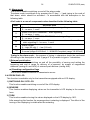
A full code is a sum of component codes described in the following table.
CODE
1
2
4
8
64
128
DESCRIPTION
Error of a measuring circle break – dynamic signalling
0 – no error, 1- error
Errors in the ADC transmitter – static signalling,
0 – no error, 1- error
Errors of RAM, EEPROM, PROGRAM - static signalling
0 – no error, 1- error
Errors in the local quartz oscillator, processor or transmitter oscillator static signalling 0 – no error, 1- error
Alarm current
0 – high (22 mA), 1 – low (3.6 mA)
Current range Mod
0-normal (range 3.9-20.5mA, 1 – NAMUR-Compilant (range 3.8-20.5mA)
Typing in the alarm code – the process of typing in characters should be performed
according to the description in item 2) page 9. It is possible to type in 3 characters.
l) External push-button
This function enables switching on and off the possibility of zeroing and setting the
beginning and end of range by delivery of a pressure, by means of magnetised
elements (casing AL and ALW) or external push-buttons (casing ALE).
m) Resetting configuration flags
This function enables removal of transmission errors.
8.4 OPERATING LCD
This function is available only for the transmitters equipped with an LCD display.
1) SWITCHING ON / OFF LCD.
This function enables switching on and off the LCD display.
2) REVERSE
This function enables displaying values on the transmitter’s LCD display in the reverse
form.
3) TURN
This function enables turning the values displayed on the LCD display by 180º.
After executing this function the message about restarting is displayed. The effect of the
turning of the displaying is visible after the restarting.