1
SOFTWARE MANUAL
α
SIMPLE APPLICATION CONTROLLER
α Seires Simple Application Controllers
Foreword
• This manual contains text, diagrams and explanations which will guide the reader in the
correct programming and operation of the α/α2 series controller.
• Before attempting to install or use the α/α2 Series Controller this manual should be read and
understood.
• If in doubt at any stage of the installation of the α/α2 Series Controller always consult a
professional electrical engineer who is qualified and trained to local and national standards
which apply to the installation site.
• If in doubt about the operation or use of the α/α2 Series Controller please consult the nearest
Mitsubishi Electric distributor.
• Under no circumstances will Mitsubishi Electric be liable or responsible for any consequential
damage that may arise as a result of the installation or use of this equipment.
• All examples and diagrams shown in this manual are intended only as an aid to understanding
the text, not to guarantee operation. Mitsubishi Electric will accept no responsibility for actual
use of the product based on these illustrative examples.
• Please contact a Mitsubishi Electric distributor for more information concerning applications in
life critical situations or high reliability.
• This manual is subject to change without notice.
This manual confers no industrial property rights or any rights of any other kind, nor does it
confer any patent licenses. Mitsubishi Electric Corporation cannot be held responsible for any
problems involving industrial property rights which may occur as a result of using the contents
noted in this manual.
© 2005 MITSUBISHI ELECTRIC CORPORATION
α Series Simple Application Controllers
AL-PCS/WIN-E
Software Manual
Manual number : JY992D74001
Manual revision : P
Date
: 4/2015
i
α Series Simple Application Controllers
ii
α Series Simple Application Controllers
Guidelines for the safety of the user and protection of AL-PCS/WIN-E
This manual provides information for the use of AL-PCS/WIN-E. The manual has been written
to be used by trained and competent personnel. The definition of such a person or persons is
as follows;
a) Any engineer who is responsible for the planning, design and construction of automatic
equipment using the product associated with this manual should be of a competent
nature, trained and qualified to the local and national standards required to fulfill that
role. These engineers should be fully aware of all aspects of safety with regards to
automated equipment.
b) Any commissioning or service engineer must be of a competent nature, trained and
qualified to local and national standards required to fulfill that job. These engineers
should also be trained in the use and maintenance of the completed product. This
includes being completely familiar with all associated documentation for the said
product. All maintenance should be carried out in accordance with established safety
practices.
c) All operators of the completed equipment (see Note) should be trained to use that
product in a safe manner in compliance to established safety practices. The operators
should also be familiar with documentation which is connected with the actual operation
of the completed equipment.
Note : the term ‘completed equipment’ refers to a third party constructed device which
contains or uses the product associated with this manual.
Notes on the symbology used in this manual
At various times through out this manual certain symbols will be used to highlight points of
information which are intended to ensure the users personal safety and protect the integrity of
equipment. Whenever any of the following symbols are encountered its associated note must
be read and understood. Each of the symbols used will now be listed with a brief description of
its meaning.
Hardware warnings
1) Indicates that the identified danger WILL cause physical and property damage.
2) Indicates that the identified danger could POSSIBLY cause physical and property
damage.
3) Indicates a point of further interest or further explanation.
Software warning
4) Indicates special care must be taken when using this element of software.
5) Indicates a special point of which the user of the associated software element
should be aware.
6) Indicates a point of interest or further explanation.
iii
α Series Simple Application Controllers
• Under no circumstances will Mitsubishi Electric be liable or responsible for any
consequential damage that may arise as a result of the installation or use of this equipment.
• All examples and diagrams shown in this manual are intended only as an aid to
understanding the text, not to guarantee operation. Mitsubishi Electric will accept no
responsibility for actual use of the product based on these illustrative examples.
• Please contact a Mitsubishi distributor for more information concerning applications in life
critical situations or high reliability.
iv
α Series Simple Application Controllers
Further Information Manual Lists
Manual Name
{
α Software Manual
<This manual>
{
α Hardware Manual
~
α Programming Manual
{
Manual No.
JY992D74001
Description
This manual contains explanations of operation
for AL-PCS/WIN-E Programming Software.
This manual contains hardware explanations for
JY992D74201 wiring, installation and specification for α series
controllers.
JY992D76601
This manual contains instruction explanations for
the α Series controllers.
α Series Instruction Manual
JY992D90901
This manual contains hardware explanations of
installation for α Series controller.
{
AL-EEPROM
Hardware Manual
JY992D74301
This manual contains hardware explanations of
installation for AL-EEPROM.
{
α2 Hardware Manual
This manual contains hardware explanations for
JY992D97301 wiring, installation and specification for α2 series
controllers.
~
α2 Programming Manual
<English only>
<English only>
α2 Series Communication
JY992D97101
This manual contains instruction explanations for
the α2 Series controllers.
User’s Manual
<English only>
This manual contains explanations for the setup,
JY992D97701 messaging, diagnostics, bit assignments, etc. for
communications using the α2 series controller.
α2 Series Instruction Manual
JY992D97501
AL2-4EX, AL2-4EX-A2,
AL2-4EYR, AL2-4EYT
Instruction Manual
This manual contains hardware explanations of
JY992D97401 installation for AL2-4EX, AL2-4EX-A2, AL24EYR and AL2-4EYT extension module.
AL2-2DA Instruction Manual
JY997D09301
This manual contains hardware explanations of
installation for AL2-2DA expansion module.
AL2-2PT-ADP Instruction
Manual
JY997D09401
This manual contains hardware explanations of
installation for AL2-2PT-ADP expansion module.
AL2-2TC-ADP Instruction
Manual
JY997D09501
This manual contains hardware explanations of
installation for AL2-2TC-ADP expansion module.
AL2-EEPROM-2
Hardware Manual
JY992D96801
This manual contains hardware explanations of
installation for AL2-EEPROM-2.
AL-232CAB
Hardware Manual
JY992D76001
This manual contains hardware explanations of
installation for AL-232CAB.
AL2-GSM-CAB
Hardware Manual
JY992D97201
This manual contains hardware explanations of
installation for AL2-GSM-CAB.
{
AL-ASI-BD, AL2-ASI-BD
Hardware Manual
This manual contains hardware explanations for
JY992D81401
wiring, installation and specification, etc. for ALJY992D81402
ASI-BD and AL2-ASI-BD.
{
This manual contains hardware explanations of
installation for α2 Series controller.
~ Refer to these manuals.
{ Refer to this manual if necessary.
Refer to the content of these manuals if necessary though it is included in α2 Hardware
Manual.
v
α Series Simple Application Controllers
Definitions
The following terms will be used throughout this manual and the AL-PCS/WIN-E programming
software.
Function Block Programming - The method by which the α Simple Application Controller is
programmed.
Function Blocks - the heart of the α series. They process information received from inputs or
other sources, manipulate the data, and control the system Outputs. There are 40 (α series:
26, α2 series: 40) function blocks that can be found in the Accessories Toolbar under the
FUNC or LOGIC headings. The function blocks have been pre-programmed to perform
specific actions and may have variable parameters that can be adjusted for specific
programming needs.
Function Block Diagram base (FBD base) - All system program components (Inputs,
Outputs, Function Blocks, Memory Bits, or Keys) are placed on the FBD base during
programming.
Digital - A type of Input or Output that only recognizes an On or Off state. An On state can also
be referred to as “High” or “1” while the Off state can be referred to as “Low” or “0”.
Analog - A type of input/output that measures a Voltage or Ampere value rather than an On/
Off signal.
Abbreviations
The following definitions or abbreviations will be used throughout this manual.
• The AL-PCS/WIN-E software will be referred to as the AL-PCS/WIN-E or the programming
software.
• The α and α2 Series Simple Application Controller may be referred to as the α series or
the controller.
• Function Blocks may be referred to as FB(s).
• Function Block Diagram may be referred to as FBD.
• Input/Output may be referred to as I/O.
• Personal Computer may be referred to as PC
• Microsoft® Windows®, Windows® 95, Windows® 98, Windows® Me, WindowsNT®
Workstation 4.0, Windows® 2000, Windows® XP, Windows Vista® and Windows® 7 may be
referred to generically as Windows®.
Registration
• Microsoft® Windows®, Windows® 95, Windows® 98, Windows® Me, WindowsNT®
Workstation 4.0, Windows® 2000, Windows® XP, Windows Vista® and Windows® 7 are
either registered trademarks or trademarks of Microsoft Corporation in the United States
and/or other countries.
• The company name and the product name to be described in this manual are the
registered trademarks or trademarks of each company.
vi
α Series Simple Application Controllers
Table of Contents
Safety Guidelines ................................................................................ iii
1. Introduction ..........................................................................................1-1
1.1 Outline ................................................................................................................. 1-1
1.1.1 Major Features of the AL-PCS/WIN-E Software........................................................ 1-1
1.2 System Configuration .......................................................................................... 1-2
1.2.1 Direct Connection with AL-PCS/WIN-E ..................................................................... 1-2
1.2.2 Remote Maintenance With AL-PCS/WIN-E............................................................... 1-2
1.3 Applicable Controllers.......................................................................................... 1-3
1.4 Version Up Lists .................................................................................................. 1-3
1.5 Product Configuration .......................................................................................... 1-4
2. Installing and Starting AL-PCS/WIN-E.................................................2-1
2.1
2.2
2.3
2.4
System Requirements ......................................................................................... 2-1
Installing AL-PCS/WIN-E ..................................................................................... 2-2
Uninstalling AL-PCS/WIN-E ................................................................................ 2-3
Starting AL-PCS/WIN-E....................................................................................... 2-4
3. Using the Help Files.............................................................................3-1
3.1 The F1 Key .......................................................................................................... 3-1
3.2 The Context Help................................................................................................ 3-2
3.3 Help in Menu Bar ................................................................................................. 3-2
3.3.1
3.3.2
3.3.3
3.3.4
3.3.5
3.3.6
3.3.7
The Contents Command or Tab ................................................................................ 3-3
Search for Help On.................................................................................................... 3-4
The Contents Tab...................................................................................................... 3-4
The Index Tab ........................................................................................................... 3-5
The Find Tab ............................................................................................................. 3-6
How to Use Help ....................................................................................................... 3-6
About SW0D5-ALVLS-E............................................................................................ 3-6
4. What You Should Know Before Starting to Program ...........................4-1
4.1
4.2
4.3
4.4
Screen Identification ............................................................................................ 4-1
The Function Block Diagram (FBD) Window ....................................................... 4-3
The Monitoring in System Sketch Window .......................................................... 4-4
The Programming Mode ...................................................................................... 4-5
4.4.1 The FBD Window in Programming Mode .................................................................. 4-5
4.4.2 “Monitoring in System Sketch Window” in the Programming Mode .......................... 4-5
4.5 The Simulation Mode........................................................................................... 4-5
4.6 The Monitor Mode ............................................................................................... 4-5
vii
α Series Simple Application Controllers
5. Menu Bar Functions.............................................................................5-1
5.1
5.2
5.3
5.4
5.5
5.6
5.7
5.8
5.9
5.10
5.11
File....................................................................................................................... 5-1
Edit ...................................................................................................................... 5-2
View ..................................................................................................................... 5-3
Insert.................................................................................................................... 5-4
Tools .................................................................................................................... 5-4
Search ................................................................................................................. 5-4
Controller ............................................................................................................. 5-5
Com ..................................................................................................................... 5-8
Option .................................................................................................................. 5-9
Window ................................................................................................................ 5-9
Help ................................................................................................................... 5-10
6. Function Block Diagram (FBD) Programming......................................6-1
6.1 Opening a New File ............................................................................................. 6-1
6.2 Component Items (Icons) of the Program ........................................................... 6-2
6.2.1
6.2.2
6.2.3
6.2.4
6.2.5
6.2.6
6.2.7
6.2.8
6.2.9
FBD Base .................................................................................................................. 6-2
Inputs......................................................................................................................... 6-3
Outputs ...................................................................................................................... 6-4
Operation Keys.......................................................................................................... 6-4
System Bits ............................................................................................................... 6-5
Control Bits ................................................................................................................ 6-7
Logic Function Blocks ............................................................................................... 6-8
Function Blocks ......................................................................................................... 6-9
User Function Blocks .............................................................................................. 6-11
6.3 Arrangement of Icons and Resize FBD Base .................................................... 6-12
6.3.1
6.3.2
6.3.3
6.3.4
6.3.5
6.3.6
Arrangement of Icons .............................................................................................. 6-12
Moving Icons ........................................................................................................... 6-12
Deleting of Icon ....................................................................................................... 6-13
Moving Input and Output Rectangles ...................................................................... 6-13
Resize FBD Base .................................................................................................... 6-13
Select Controller Type ............................................................................................. 6-14
6.4 Connection (Wiring) between Icons................................................................... 6-15
6.4.1 Input and Output Pins.............................................................................................. 6-15
6.4.2 Connection (Wiring) between Icons ........................................................................ 6-15
6.5 Setup Icons........................................................................................................ 6-17
6.5.1 Comments ............................................................................................................... 6-17
6.5.2 Parameter of Function Blocks ................................................................................. 6-17
6.6 Auto FBD Wizard (Only AL-**M*-*).................................................................... 6-18
6.6.1
6.6.2
6.6.3
6.6.4
6.6.5
6.6.6
6.6.7
Choose an Output (Step 1) ..................................................................................... 6-19
Choose Function Blocks (Step 2, 3) ........................................................................ 6-20
Select Signal Order (Step 4) ................................................................................... 6-21
Adding a Logical Condition (Step 5) ........................................................................ 6-21
Select Input Signals to Drive Functions (Step 6) ..................................................... 6-22
Setting Parameters (Step 7) .................................................................................... 6-26
Operation Check (Step 8)........................................................................................ 6-27
6.7 Display Manager................................................................................................ 6-28
6.8 Register the User Function Block ...................................................................... 6-37
6.8.1 Export Registered User Function Block .................................................................. 6-39
6.8.2 Import Registered User Function Block................................................................... 6-40
6.9 Change FBD Base Colors and Icons................................................................. 6-40
6.9.1 Change FBD Base Colors ....................................................................................... 6-40
6.9.2 Customize Icons ...................................................................................................... 6-40
viii
α Series Simple Application Controllers
7. Monitoring in System Sketch Window..................................................7-1
7.1 Monitoring in System sketch Base Resize .......................................................... 7-2
7.2 Change Base Color and Icons............................................................................. 7-2
7.2.1 Changing the Base Color .......................................................................................... 7-2
7.2.2 Customize Icons ........................................................................................................ 7-2
7.3 Drawing Lines, Ovals, and Rectangles................................................................ 7-3
7.3.1 Moving and Resizing Lines, Ovals, and Rectangles ................................................. 7-3
7.3.2 Changing Colors........................................................................................................ 7-3
7.3.3 Changing the Line Width ........................................................................................... 7-3
7.4 LCD Display Image.............................................................................................. 7-3
7.5 Adding an OLE File ............................................................................................. 7-4
7.6 Adding a Signal or Function Block....................................................................... 7-4
8. Simulation Mode ..................................................................................8-1
8.1 Display of the Signal Icon, Wire and Function Block ........................................... 8-1
8.1.1 Input and Output Icons .............................................................................................. 8-1
8.1.2 Wire ........................................................................................................................... 8-1
8.1.3 Function Block ........................................................................................................... 8-1
8.2
8.3
8.4
8.5
Start the Simulation Mode ................................................................................... 8-1
Turn Signals ON/OFF (Force ON/OFF)............................................................... 8-2
Change Function Block Parameters .................................................................... 8-2
Exiting the Simulation Mode ................................................................................ 8-2
9. Read/Write Program From/To Controller .............................................9-1
9.1 Write Program to Controller ................................................................................. 9-1
9.2 Read Program from Controller ............................................................................ 9-2
10. Monitoring ..........................................................................................10-1
10.1 Display of the Signal Icon, Wire and Function Block ......................................... 10-2
10.1.1 Input and Output Icons ............................................................................................ 10-2
10.1.2 Wire ......................................................................................................................... 10-2
10.1.3 Function Block ......................................................................................................... 10-2
10.2
10.3
10.4
10.5
Start the Monitor Mode ...................................................................................... 10-2
Turn Signals ON/OFF (Force ON/OFF)............................................................. 10-3
Change Function Block Parameters .................................................................. 10-3
Exiting the Monitor Mode ................................................................................... 10-4
ix
α Series Simple Application Controllers
11. Remote Maintenance.........................................................................11-1
11.1 System Configuration ........................................................................................ 11-1
11.2 Cable Reference................................................................................................ 11-2
11.2.1 User made RS-232C Cable Between Modem and AL-232CAB
(Model Type: AL-**M*-*) .......................................................................................... 11-2
11.2.2 RS-232C Straight Cable Between Modem (GSM Modem) and AL2-GSM-CAB
(Model Type: AL2-14MR-*, AL2-24MR-*)................................................................ 11-2
11.3 Recommended Modems ................................................................................... 11-3
11.4 Modem Initialization at the Controller side......................................................... 11-3
11.4.1 Modem Setting ........................................................................................................ 11-3
11.4.2 Set the Modem Initialization .................................................................................... 11-5
11.4.3 Set the GSM Modem Initialization ........................................................................... 11-7
11.5
11.6
11.7
11.8
PC to Modem Configuration Check ................................................................... 11-9
Connecting the Modem Telephone Line.......................................................... 11-10
Data Transfer................................................................................................... 11-11
Disconnecting the Telephone Line .................................................................. 11-11
12. Setting for Computer Link (AL2-14MR-*, AL2-24MR-*) .....................12-1
12.1 Setting for the Computer Link ............................................................................ 12-1
13. Information about AS-interface Programming....................................13-1
13.1 AS-interface Input Icon and System Bit Icon ..................................................... 13-2
13.1.1 AS-interface Input Icon ............................................................................................ 13-2
13.1.2 ASI System Bits Icon ............................................................................................... 13-2
13.2 AS-interface Output Icons and Control Bit Icon ................................................. 13-3
13.2.1 AS-interface Output Icon ......................................................................................... 13-3
13.2.2 Active/Passive State................................................................................................ 13-4
14. When Russian Is Used ......................................................................14-1
14.1 How to Input Russian ........................................................................................ 14-1
14.2 The Setting of the Multi-Language Function of Windows®.....................................................14−1
14.2.1 In the Case of Windows® 2000 ............................................................................... 14-2
14.2.2 In the Case of Windows® XP .................................................................................. 14-2
14.2.3 In the Case of Windows Vista® and Windows® 7 ................................................... 14-3
x
α Series Simple Application Controllers
1.
Introduction 1
Introduction
This section describes the major functions of the AL-PCS/WIN-E programming software
(hereafter referred to the AL-PCS/WIN-E or programming software) and the outline of this
manual.
This Software Manual is written for AL-PCS/WIN-E version V2.60. Further version of AL-PCS/
WIN-E may change without notice. Refer to the help file for AL-PCS/WIN-E's changes.
1.1
Outline
The software package AL-PCS/WIN-E is a programming tool designed to be used with the α
Series Simple Application Controllers ( α and α 2 series). The AL-PCS/WIN-E runs on
Microsoft ® Windows ® 95, Windows ® 98, Windows ® Me, WindowsNT ® Workstation 4.0,
Windows® 2000, Windows ® XP, Windows Vista® and Windows ® 7 (hereafter referred to
collectively as Windows®). The software has been designed to be both powerful and user
friendly. While many of the software features can be learned intuitively, a detailed help file has
been incorporated into the software to assist users in finding answers to their questions.
1.1.1
Major Features of the AL-PCS/WIN-E Software
The AL-PCS/WIN-E is a powerful tool for programming the α Series and α2 Series Simple
Application Controller (hereafter referred to the α Series or controller) in Function Block style.
The Visual Nature of the software helps the user to see and understand the relationships
between all parts of the program. Powerful and easy to use, the AL-PCS/WIN-E has
incorporated the following features for your convenience:
• User-friendly Programming
The program can be made the visually and easily.
The Software has been designed to operate in a user-friendly windows format.
• Monitoring and force ON/OFF
Real-time monitoring AL-PCS/WIN-E allows bit device testing.
• Simulation function
When the simulation function is used, operation of the program can be tested off-line.
• Remote maintenance function
The software allows remote maintenance function to download, and to up-load and to
monitor the program to the α series via telephone line.
• Monitoring in System Sketch window
The customer can make the monitor screen for the customer’s system in the Monitoring in
System Sketch Window.
• User-defined function block
The user can create customize function block from the combination of the original function
blocks.
• Auto wizard function (Only supports AL-**M-* model)
This function allows beginners to create function block program with the aid of a guidance
window.
• Russian Input
The VLS Software (V2.50) corresponds to the Russian input of α2 (V3.00).
For details, refer to Chapter 14.
1-1
α Series Simple Application Controllers
Introduction 1
1.2
System Configuration
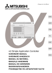
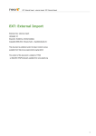
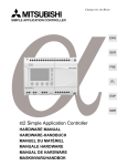
1.2.1
Direct Connection with AL-PCS/WIN-E
Figure 1.1: Direct Connection with AL-PCS/WIN-E
α, α2
AL-232CAB
Series
Personal computer
(AL-PCS/WIN-E)
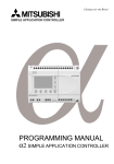
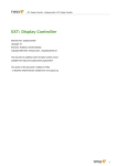
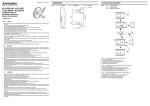
1.2.2
Remote Maintenance With AL-PCS/WIN-E
Figure 1.2: Remote Maintenance with AL-PCS/WIN-E
Modem
Modem
Modem
1
Personal computer
(AL-PCS/WIN-E)
α
Modem
1
2
3
Series
or
AL210MR-*
4
g
α2
Series
Modem
1
GSM
Modem
g
AL214MR-*
AL224MR-*
Table 1.1: Connecting by Modem
Using Cable
1
RS-232C straight cable for the modem (specified by Modem manufacture)
2
User made RS-232C cable (Refer to Figure 11.2)
3
AL-232CAB
4
RS-232C straight cable for the modem (Refer to Figure 11.3)
5
AL2-GSM-CAB
1-2
α Series Simple Application Controllers
1.3
Introduction 1
Applicable Controllers
Table 1.2: Applicable Controllers
AL-PCS/WIN-E Version
(SW0D5C-ALVLS-E)
Model Name
AL-6MR-A
AL-10M*-*
Version 1.00 or later
AL-20M*-*
AL2-14MR-*
AL2-24MR-*
AL2-10MR-*
1.4
Version 2.00 or later
Version 2.40 or later
Version Up Lists
Table 1.3: History of AL-PCS/WIN-E (SW0D5C-ALVLS-E)
Version
V1.00
Description
Supported α Series controllers with Windows® 95, Windows® 98 and
WindowsNT® workstation 4.0.
V1.30
Supported AL-ASI-BD AS-interface module.
V1.41
For Windows® Me and Windows® 2000.
V2.00
Supported α2 Series controllers.
V2.10
•
•
•
V2.30
Supported α2 Series controllers Version 2.00.
• Radio clock (DCF 77 [Manufactured by Theben AG])
• AL2-2DA analog output module
• AL2-2PT-ADP PT100 adaptor module
• AL2-2TC-ADP thermocouple analog sensor adaptor module
• New function block (Analog Output [AO], PID [PID])
V2.40
Supported AL2-10MR-*.
Supported α2 Series controllers Version 2.20.
• New function block (Short Message Receiving [SMR], Call Detect [CD])
• Enhanced Daylight Saving Time Setup.
• Enhanced User Program Protection.
Replace signals.
Import/Export of the Time Switch Setup.
V2.50
Supported α2 Series controllers Version 3.00.
• The addition of menu language setting
• The addition of menu call key setting
• The addition of the Russian input
V2.60
•
•
For Windows Vista®
For Windows® 7
V2.70
•
For Windows® 7 64 bit version.
For Windows® XP
Up to COM10 is available for COM port setting
The Import/Export function for User Function Block programming is
added.
1-3
α Series Simple Application Controllers
1.5
Introduction 1
Product Configuration
Check the contents of the AL-PCS/WIN-E box against this list to confirm that the following
accessories are supplied.
Table 1.4: Product Configuration
Items
Number
Description
CD-ROM
1
SW0D5C-ALVLS-E
Manual (this manual)
1
Manual number JY992D74001
1-4
α Series Simple Application Controllers
2.
Installing and Starting AL-PCS/WIN-E 2
Installing and Starting AL-PCS/WIN-E
This section describes how to install the AL-PCS/WIN-E programming software package and
to connect the α Simple Application Controller to the Personal Computer. The Operation
System requirements are outlined and the equipment necessary to make all proper
connections are detailed.
2.1
System Requirements
The AL-PCS/WIN-E is designed to be installed on a computer that meets or exceeds the
following specifications. Please check whether your personal computer meets these
requirements prior to the software installation.
Table 2.1: Personal Computer Requirements
Item
Description
32 bit version
• Microsoft® Windows® 95
Operating System*1
•
•
•
•
•
•
Microsoft® Windows® 98
Microsoft® Windows® Millennium Edition
Microsoft® WindowsNT® 4.0 Workstation (Service Pack3 or later)
Microsoft® Windows® 2000 Professional
Microsoft® Windows® XP (Home Edition, Professional)
Microsoft® Windows Vista®
(Home Basic, Home Premium, Business, Ultimate, Enterprise)
Microsoft® Windows® 7
(Ultimate, Enterprise, Professional, Home Premium, Starter)
64 bit version
• Microsoft® Windows® 7
(Ultimate, Enterprise, Professional, Home Premium)
•
CPU*2
Pentium 133 MHz or more (recommended)
Hard Disk
*2
10 MB of free capacity
Memory
32 MB or more (recommended)
CD-ROM Drive
Required for Setup
Pointing Device
Mouse or other pointing device
Display*2
SVGA (800 x 600) 256 colors or more (recommended)
RS-232C Serial Interface
1 port or more
The RS-232C serial interface must be assigned to a COM port (COM1 to
COM10).
*1 The Russian input should use Russian OS (Windows®) when OS (Windows®) to be
used is Windows® 2000, Windows® XP, Windows Vista® or Windows® 7, Russian can
be entered on VLS by using the Windows® multi-language function.
For details, refer to Chapter 14.
*2 Take care that the used computer meets or exceeds the CPU, memory and display
specifications outlined by the OS.
2-1
α Series Simple Application Controllers
2.2
Installing and Starting AL-PCS/WIN-E 2
Installing AL-PCS/WIN-E
To install the AL-PCS/WIN-E component files from the CD-ROM. Note that this software
cannot be run from the install CD. It must be installed onto hard-drive and subsequently run
the software from the drive.
Note:
If the PC had been installed with AL-PCS/WIN-E, please uninstall it. If it is uninstalled
before the install, the AL-PCS/WIN-E may not operate correctly. For uninstall, refer to
section 2.3.
To install AL-PCS/WIN-E:
1) Restart Windows®, and do not start-up any other applications.
2) Insert the SW0D5C-ALVLS-E CD into CD-ROM drive.
3) Execute “setup.exe.”
4) During the SW0D5-ALVLS-E Setup dialog box, click “NEXT” whenever ready thus
proceeding to the next panel.
5) If the destination folder need to be changed for the AL-PCS/WIN-E component files, click
“Browse”, and use the browser to locate the appropriate destination.
6) Click “NEXT”.
7) If the Program folders need to be changed for the AL-PCS/WIN-E, enter the program folder
name.
Note: When using on Windows Vista® and Windows® 7
If the destination folder changes to an arbitrary folder (user created), it is not necessary to start the
program via "Run as Administrator". For starting AL-PCS/WIN-E, refer to section 2.4.
8) Click “NEXT” to begin the installation. When the process is complete, a message will follow
indicating. He successful installation of the AL-PCS/WIN-E software.
9) Select “Yes, I want to restart my computer now”, and Click “Finish” to restart your computer.
2-2
α Series Simple Application Controllers
2.3
Installing and Starting AL-PCS/WIN-E 2
Uninstalling AL-PCS/WIN-E
It is possible to remove all of the AL-PCS/WIN-E component files installed on your system with
the Install/Uninstall in the Control Panel.
To uninstall AL-PCS/WIN-E:
1) Click the "Start" Menu, select "Settings" and then "Control Panel."
Note:
-
Click the "Start" menu, choose "Control Panel" in Windows® XP, Windows Vista® and Windows® 7.
2) Double-click "Add/Remove Programs" in the control panel.
Note:
-
Click "Add or Remove Programs" on the control panel in Windows® XP.
-
Click "Programs" on the control panel in Windows Vista® and Windows® 7.
3) Select "Install/Uninstall" tab on Add/Remove Programs property.
Note:
-
Select "Change or Remove Programs" on "Add/Remove Programs" window in Windows® 2000.
-
Select "Change or Remove Programs" on "Add or Remove Programs" window in Windows® XP.
-
Double-click "Uninstall a program" of "Programs and Features" in Windows Vista® and Windows® 7.
4) Select "Mitsubishi SW0D5-ALVLS-E" to uninstall.
Note:
-
Double-click "Mitsubishi SW0D5-ALVLS-E" to uninstall in Windows Vista® and Windows® 7, and go
to step 6.
5) Click [Change/Remove] button.
6) Click “Yes” to begin the uninstall of the AL-PCS/WIN-E component files. When the process
is complete, a AL-PCS/WIN-E is successfully uninstalled from your personal computer.
2-3
α Series Simple Application Controllers
2.4
Installing and Starting AL-PCS/WIN-E 2
Starting AL-PCS/WIN-E
This software cannot be run from the install CD. It must be installed onto hard-drive and
subsequently run the software from the drive.
To start AL-PCS/WIN-E:
• Click the “Start” menu, choose “Program” ⇒ “Mitsubishi Alpha Controller”, and click the
name of the program you want to start.
Note:
-
"All Programs" appears in Windows® XP, Windows Vista® and Windows® 7.
• It is possible to also double-click a program icon (shortcut) to begin start-up.
Caution; Starting AL-PCS/WIN-E on Windows Vista® and Windows® 7.
When starting on Windows Vista® and Windows® 7, AL-PCS/WIN-E must be started by
following method.
If it starts by other methods, AL-PCS/WIN-E does not operate correctly.
• Run AL-PCS/WIN-E as an administrator.
When starting by the Start menu and program icon (shortcut), it starts by "Run as
Administrator" in the menu of a right-click. (Refer to the section below on “How to run ALPCS/WIN-E as an administrator”).
• Installation to the arbitrary folder (user created)
The installation destination of AL-PCS/WIN-E is installed in the arbitrary folder (user
created). The starting method is the same as Windows® XP.
How to run AL-PCS/WIN-E as an administrator
When starting through the Start menu or through a program icon (shortcut), right-click on
the program icon or menu item and select "Run as Administrator."
Start Menu
Shortcut
2-4
α Series Simple Application Controllers
Installing and Starting AL-PCS/WIN-E 2
Note; When user account control is enabled in Windows Vista® and Windows® 7
The following dialog box appears when starting. Click "Allow."
Note;
With Windows Vista® and Windows® 7, all users can run AL-PCS/WIN-E as an
administrator by the following method.
1) Right-click the "Alpha Programming" in Start
menu, and choose "Properties".
"Alpha programming Properties" dialog box
appears.
2-5
α Series Simple Application Controllers
Installing and Starting AL-PCS/WIN-E 2
2) Select "Compatibility" tab, and then click
"Show settings for all users" button.
“Vls Properties” dialog box appears.
Note;
“User Account Control” dialog box appears
when user account control is enabled.
Click “Continue“ button.
3) Click "Run this program as an administrator"
check-box to add check mark, and then click
"OK" button.
"Vls Properties" dialog box closes.
4) Click "OK" button to complete setting.
"Alpha programming Properties" dialog box
closes.
2-6
α Series Simple Application Controllers
3.
Using the Help Files 3
Using the Help Files
The AL-PCS/WIN-E includes a powerful package of help files to guide the user through the
programming options. Use the F1 key, or click the help icon, or use the Help pull down menu to
access the help files.
Note; When using Windows Vista® and Windows® 7
When Help is run using Windows Vista® and Windows® 7, the following "Windows Help and
Support" screen may appear, and the Help screen is not displayed.
Perform the following procedure to install “WinHlp32.exe” which is needed to display the
Help screen. (Note: The personal computer needs to be connected to the internet.)
1) Click the Help button.
2) The screen shown below opens. Click the displayed link.
3) The Microsoft Support Knowledge Base page opens.
(http://support.microsoft.com/kb/917607/en-us)
Follow the instructions and download the Windows Help program for Windows Vista® and
Windows® 7 (WinHlp32.exe).
4) Install the downloaded file.
3.1
The F1 Key
The F1 key will provide specific help on a highlighted object.
Click a system component on the FBD base to highlight it and press the F1 Key to bring up a
dialog screen. To receive Help on a command, move to the command with the mouse until the
instruction is highlighted. Use F1 to access the Help dialog box before using the command.
3-1
α Series Simple Application Controllers
3.2
Using the Help Files 3
The Context Help
The Context Help command can provide help with Toolbars and associated commands. When
choosing the Toolbar's Context Help button or pushing the “Shift” + “F1” key, the mouse pointer
will change to an arrow and question mark. Then click on the item needing clarification in the
application window. The Help topic will be shown for the item you clicked.
Context Help button
3.3
Help in Menu Bar
It is possible to also get Help by
clicking “Contents” and “Search for
Help on...” (Help menu).
Upon entering the Help menu the
options list will be shown.
When “Search for Help On...” or “How to Use
Help...” is chosen, three tabs will appear on
top of the window. These tabs can be used in
addition to the Help files available on the
display.
3-2
α Series Simple Application Controllers
3.3.1
Using the Help Files 3
The Contents Command or Tab
The contents menu allows the user to choose from the following categories or chapters. When
an option is chosen, the main topics available for that category pop up on screen. Choose the
desired topic to bring up a dialog box.
Words or phrases that are highlighted in green contain addition information in another dialog
box. Click on the highlighted text to view its dialog box.
Introduction - Choose from a basic introduction, information on the FBD base, or the System
Sketch Operations.
Menu Options - Choose to view detailed information upon each pull down menu available at
the top of the screen.
Tool Bars - Explains about the Standard, Drawing, Accessories, Controller, Image and User
Function toolbar.
Functions and Signals - Learn about the functions and capabilities of the Inputs, Outputs,
and Function Blocks available for programming with the AL-PCS/WIN-E.
Various Modes of Operation - Explains about the different modes of operation including the
Programming mode, the Simulation Mode, and the Monitoring Mode.
Special features - This section describes the various ways of Dragging and Dropping objects,
and of Moving Objects with the arrow keys.
Sub FBD Window - The sub FBD window can include the part of the main FBD window or a
part of another Sub FBD window. In the FBD window, the sub FBD window is shown by “User
Func” icon. This User Func icon has some input pins and output pins according to the contents
of its Sub FBD window.
Help Support - Provides information on using the Contents Help icon, F1 key, and help dialog
boxes.
3-3
α Series Simple Application Controllers
3.3.2
Using the Help Files 3
Search for Help On...
It is possible to search the informations and instruction for using AL-PCS/WIN-E or various
pieces of reference information from the desired categories.
To search for Help:
1) Clicking “Search for Help On...” in the help menu to bring up the opening Help window.
2) Click on the desired category to bring up information and instructions for using AL-PCS/
WIN-E or various pieces of reference information.
3.3.3
The Contents Tab
The contents menu allows the user to choose from the following categories or chapters. When
an option is chosen, the main topics available for that category pop up on screen. Choose the
desired topic to bring up a dialog box.
Introduction - Choose from a basic introduction, information on the FBD base, or the System
Sketch Operations.
Menu Options - Choose to view detailed information upon each pull down menu available at
the top of the screen.
Tool Bars - Explains the Standard, Drawing, Accessories, Controller, Image and User
Function toolbar.
Functions and Signals - Learn about the functions and capabilities of the Inputs, Outputs,
and Function Blocks available for programming with the AL-PCS/WIN-E.
Various Modes of Operation - Explains about the different modes of operation including the
Programming mode, the Simulation Mode, and the Monitoring Mode.
Special features - This section describes the various ways of Dragging and Dropping objects,
and of Moving Objects with the arrow keys.
Help Support - Provides information on using the Contents Help icon, F1 key, and help dialog
boxes.
3-4
α Series Simple Application Controllers
3.3.4
Using the Help Files 3
The Index Tab
The windows provides information on index topics. Type the first few letters of the required
topic or scroll to the topic in the index list.
3-5
α Series Simple Application Controllers
3.3.5
Using the Help Files 3
The Find Tab
The Find tab generates a list of key words on the AL-PCS/WIN-E and lets you search for help
on those words. A matching words directory gives an option to narrow the number of matches
found. A third directory lists the topics in which your word appears.
Find Setup Wizard
At first, the Find tab needs to be setup. Perform the setup in accordance with the Find
Setup Wizard.
To setup Find tab:
1) Choose “Minimize database size (recommend)”, and click “NEXT”.
2) Click “Finish” to start creating the word list of AL-PCS/WIIN-E.
3.3.6
How to Use Help
Gives detailed information on “How to Use Help” and Customize the Help settings for the users
convenience. Topics include finding, copying, viewing, and printing help files and manipulating
the data in dialog boxes. Learn how to change the color or font size of a dialog box, add
comments, or bookmark especially useful information.
3.3.7
About SW0D5-ALVLS-E
Use this command to display the copyright notice and version number of your copy of AL-PCS/
WIN-E (SW0D5-ALVLS-E).
3-6
α Series Simple Application Controllers
4.
What You Should Know Before Starting to Program 4
What You Should Know Before Starting to Program
This section describes the basic functions and background information necessary to operate
the AL-PCS/WIN-E. Please read and understand this section prior to beginning your first
program.
There are two screens that can be accessed from the AL-PCS/WIN-E, the Function Block
Diagram base (FBD window) and the System Sketch Monitoring screen.
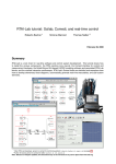
4.1
Screen Identification
The Toolbars have been labeled on the screen below for the user’s reference. These Toolbars
can be turned On or Off in the View menu. The Menu Bar runs across the top of the screen.
The two main viewing screens will be discussed later in the chapter.
Menu bar
Standard
toolbar
Image toolbar
Drawing toolbar
Controller toolbar
Accessories
toolbar
Wiring toolbar
User Function
toolbar
System Sketch Monitor window
Function Block Diagram (FBD) window
Status bar
Menu bar - The “File”, “Edit”, View”, “Insert”, “Tools”, “Search”, “Controller”, “Com”, “Option”,
“Window”, and “Help” options are located in the menu bar. Further information can be found in
the chapter 5 and Help on AL-PCS/WIN-E.
Standard toolbar - The Standard toolbar contains the “New”, “Open”, “Save”, “Cut”, “Paste”,
“Print”, “About”, “Help”, “Zoom”, and “Read from Controller” buttons. Further information can
be found in the Help on AL-PCS/WIN-E.
Image toolbar - The Image toolbar contains the “Import” and “Export” buttons within the
Monitoring in System Sketch Window. The import button is used for inserting the previously
exported image (*.img) file into the Monitoring in System Sketch Window. Further information
can be found in Help on AL-PCS/WIN-E.
Drawing toolbar - The Drawing toolbar contains the “Line”, “Rectangle”, “Oval”, “Thin”,
“Medium”, “Thick”, “Line Color”, “Brush Color”, and “Align Drawing Objects” buttons. Further
information can be found in the Help on AL-PCS/WIN-E.
4-1
α Series Simple Application Controllers
What You Should Know Before Starting to Program 4
Controller toolbar - The Controller toolbar contains the “Write to Controller”, “Verify Controller
Data”, “Diagnosis of controller”, “Run Controller”, “Stop Controller”, “FBD Auto Wizard”, “Start/
Stop Monitor”, and “Start / Stop Simulation” buttons. Further information can be found in
chapter 8 ~ 10 and Help on AL-PCS/WIN-E.
Accessories toolbar - The Accessories toolbar contains the “Input Signals”, “Functions”,
“Logic Functions”, “Output Signals”, and “User Functions” Accessory toolbar. Further
information can be found in the Help on AL-PCS/WIN-E.
Table 4.1: Accessories toolbar
Toolbar
Input Signals
Functions
Description
Input signals accessory toolbar are icons for the input signal and system bit.
Functions accessory toolbar are icons for the function blocks.
Logic Functions
Logic functions accessory toolbar are icons for the logic function blocks.
Output Signals
Output signals accessory toolbar are icons for the Output signal and control bit.
User Functions
User functions accessory toolbar are icons for the registered user function.
Wiring toolbar - The Wiring toolbar is only the “wiring” button. Further information can be
found in chapter 6 and Help on AL-PCS/WIN-E.
User function toolbar - The User function toolbar are “User Func” and “User Func
Registration” buttons. Further information can be found in the chapter 6 and the Help on ALPCS/WIN-E.
Status bar - The Status bar is current status of the “used series”, “percentage of the used
function block”, “caps lock key”, “num lock key”, and “scroll lock key”. Further information can
be found in Help on AL-PCS/WIN-E.
4-2
α Series Simple Application Controllers
4.2
What You Should Know Before Starting to Program 4
The Function Block Diagram (FBD) Window
The Function Block Diagram (FBD) window is used to program the α series controller. The
FBD window consists of a large wiring area (lime green by default), a title box and input and
output rectangles vertically along the right and left hand sides, respectively. Programming
components are placed on the wiring area or in the rectangles, and connected by single wires
to construct the program for the α series. The FBD window is also known as FBD Wiring area.
Title bar
Output
Input
Edit program area
The user can perform the following ten operations using FBD window. Refer to Chapter 6 for
more details. The size for edit program area can be changed by the operation of mouse.
1) Place the I/O signals and functions using the Accessories Toolbar.
2) Assign parameters to functions.
3) Wire the various program components together (with the help of Wiring Analyser).
4) Writes the Program logic and I/O device’s information to the α series.
5) Invoke Auto FBD Wizard to begin to program with guidance.
6) Test the program logic with Internal Devices (Input and Output signals placed in the FBD
wiring area).
7)
Simulate and check the programming logic off-line without connecting an
user can:
α series. The
- force input signals ON/OFF
- change function parameters (timers, counters, analog data, etc.)
- display comments or function values on screen
- Monitor component status via changing wire colors (ex. Red Wire = OFF, Blue Wire =
ON)
8) Read information from an α series and recreate the Program on the FBD window.
9) Monitor an α series on-line.
10) Print the FBD screen and component information shown on the FBD window.
4-3
α Series Simple Application Controllers
4.3
What You Should Know Before Starting to Program 4
The Monitoring in System Sketch Window
The Monitoring in System Sketch window is the customizing monitor window. The icons for I/O,
the function blocks, the images, and the state of LCD, etc. can be displayed in this window.
Further information can be found in chapter 7.
LCD image
object
Draw object
Function
blocks,
operation
switches
input and
output
object
Comment
object
Edit system sketch area
The following operations can be performed in System Sketch window. The size for the edit
system sketch area can be changed by the operation of mouse.
1) Draw a diagram using the Drawing toolbar.
2) Place the I/O devices and Function Blocks to represent the α series set-up.
3) Place OLE components in the System Sketch window.
4) Monitor/test an operational α series.
5) Simulate and check the programming logic without connecting the actual α series.
6) Print the System Sketch Monitor window and the component information contained in the
window.
7) Import Bitmap Images.
4-4
α Series Simple Application Controllers
4.4
What You Should Know Before Starting to Program 4
The Programming Mode
This is the mode in which all programs are created and system components are added or
deleted. Also known as the Drawing mode, all the toolbars and the menu options will be
enabled for programming or drawing. The FBD window and System sketch windows will
default to the Programming mode when files are created or opened. The indication title will be
displayed as “FBD” in the FBD window and as “Monitor in System sketch” in the System
sketch window.
4.4.1
The FBD Window in Programming Mode
As the name suggests, all the functions necessary to build a program can be accomplished in
the programming mode. The user may add FBs or other signals, set or change parameters,
move components, and perform wiring operations in the programming mode. (See Chapter 6
for more details.)
The Auto Wizard Function is also available in this mode. The main purpose of Auto FBD
Wizard is to educate inexperienced users so that they can get acquainted with Signals,
Function Blocks, Wiring and related programming items.
4.4.2
“Monitoring in System Sketch Window” in the Programming Mode
The user is allowed to add, modify, move, and resize the drawing objects in System sketch
window. Use the Accessories Toolbar to add components as in the FBD window. Copy
components to or from the FBD window. Select any component in the window by pressing the
mouse left button and drag the object to the desired location. Double click on a Function Block
to open the parameter setting dialog.
Objects can be drawn via the Drawing Tool bar with the Line, Oval, and Rectangle commands
and/or import objects with the commands in the Insert Menu.
4.5
The Simulation Mode
The Simulation mode will mimic the conditions under which a program is run without physical
connection to the hardware. This is a very powerful tool for debugging programs prior to writing
the contents to an actual target α series.
The information generated by the program will be continuously read from the Simulator. The
On/Off status and current values of the Signals and Function Blocks will be updated by the ALPCS/WIN-E or the user can input values for simulation purposes. The user can control the On/
Off state of Inputs with the click of a mouse and can directly set analog values.
4.6
The Monitor Mode
The Monitor Mode can monitor and test the actual target α series hardware which is
connected to the PC through an AL-232CAB or modem. The information regarding the state
and current value of Signals and Functions will be continuously read from the target α series
and updated accordingly in the AL-PCS/WIN-E.
If the α series contents are updated via the α series operation keys, a message box will
appear stating the α series contents are updated and monitoring will be stopped. The
application will automatically switch to Program mode.
4-5
α Series Simple Application Controllers
What You Should Know Before Starting to Program 4
MEMO
4-6
α Series Simple Applicaton Controllers
5.
Menu Bar Functions 5
Menu Bar Functions
This chapter gives a brief description of the available functions contained in the Pull Down
menus.
Menu bar
5.1
File
New (Ctrl+N) - Creates a new file with windows in both the FBD and Monitoring in System
Sketch window. When the FBD window and the system sketch monitor window have already
been displayed, the dialog box to save the file under the display is viewed.
Open... (Ctrl+O) - Opens an existing file with windows in both the FBD and Monitoring in
System Sketch window. When the FBD window and the system sketch monitor window have
already been displayed, the dialog box to save the file under the display is viewed.
Close - Closes existing active documents in both the FBD and System Sketch window, and the
dialog box to preserve the file under the display is viewed.
Save (Ctrl+S) - Saves (overwrites) the current file to its current name and directory. When
creating new file, this process is same as “Save As...”.
Save As... - Saves the current file under a new name and or directory. The first time a file is
saved this command will come up so that the file can be named.
Print Setup... - Selects a printer and printer connection from the Print Setup Dialog Box that
appears on the screen.
Print Preview - Views the active document as it would appear if printed. This command is
disabled if either of the FBD or Monitoring in System Sketch window is minimized.
Print... (Ctrl+P) - A Print Dialog box appears onscreen for selecting options and Print data.
Export Registered User Func - The registered UserFunc data (User Function Bock) is
exported (stored) to a designated folder; Thus, registering the UserFunc data (User Function
Block) is possible from one PC to another.
Import Registered User Func - The exported UserFunc data (User Function Block) is
imported from a designated folder; Thus, registering/transferring the UserFunc data (User
Function Block) is possible from one PC to another.
Recent File(Max.8) - Displays the history of the file opened in the past. The histories are
displayed up to 8 for the one preserved as a file. Moreover, by selecting the arbitrary file from
the displayed history, and selecting; The file that has been opened in the past can be opened
again.
Exit - Ends the VLS session. When the displayed file was not saved, the dialog box to
preserve the file under the display is viewed.
5-1
α Series Simple Applicaton Controllers
5.2
Menu Bar Functions 5
Edit
Undo (Ctrl+Z) - Cancels the Previous Instruction. There is only one level of Undo available.
Redo (Ctrl+Y) - Cancels the Previous Undo Instruction. There is only one level of Redo
available.
Cut (Ctrl+N) - Removes the selected data from the Screen and place it to the Clipboard.
Copy (Ctrl+C) - Copy the selected data to the Clipboard.
Paste (Ctrl+V) - Adds the data from the Clipboard to the Program
Delete (Del) - Deletes the selected data from the program.
Select All (Ctrl+A) - Select All the function blocks on the screen.
Insert Func - Inserts a new function block on the FBD window or on the Monitoring in System
Sketch Window. Select the function block to be inserted. Click the position where the function
block to be placed on the FBD window or the Monitoring in System Sketch Window.
Change Func - Changes the function block placed by the FBD window or the Monitoring in
System Sketch Window. Select the function block to be placed newly after the icon to be
altered is clicked.
Insert Logic - Inserts a new logic block on the FBD window or on the Monitoring in System
Sketch Window. Select the logic block to be inserted. Click the position where the logic block is
to be placed on the FBD window or on the Monitoring in System Sketch Window.
Change Logic - Changes the logic block placed by the FBD window or the Monitoring in
System Sketch Window. Select the logic block to be put newly after the icon to be changed is
selected.
5-2
α Series Simple Applicaton Controllers
5.3
Menu Bar Functions 5
View
Close (Open) System Sketch - Closes the System Sketch Screen. If the screen is closed, the
title will change to Open System Sketch.
Close (Open) FBD - Closes the Function Block Diagram base. If closed, the menu option will
change to Open FBD.
Standard Toolbar - When the Check mark appears, the Standard Toolbar will be displayed
onscreen.
Controller Toolbar - When the Check mark appears, the Controller Toolbar will be displayed
onscreen.
Drawing Toolbar - When the Check mark appears, the Drawing Toolbar will be displayed
onscreen.
Accessories Toolbar - When the Check mark appears, the Accessories Toolbar will be
displayed Onscreen.
Wiring Toolbar - When the Check mark appears, the Wiring Toolbar will be displayed
onscreen.
Image Toolbar - When the Check mark appears, the Image Toolbar will be displayed
onscreen.
User Function Toolbar - When the Check mark appears, the User Function Toolbar will be
displayed onscreen.
Status Bar - When the Check mark appears, the Status Bar will be displayed Onscreen.
Zoom - Choose from 200 (Ctrl+PageUp), 150, 100 (Ctrl+Home), 75, 50 (Ctrl+PageDown), 25,
or 10% zoom factors.
5-3
α Series Simple Applicaton Controllers
5.4
Menu Bar Functions 5
Insert
LCD Image - Displays the same content as the liquid crystal display of the
image is active only in the Monitoring in System Sketch Window.
α series. LCD
Comment - The FBD window and the Monitoring in System Sketch Window displays
comment. The comment control statement is not limited to a number of strokes with this
software.
Insert New Object... - Inserts the data made by other applications as a display panel item on
the Monitoring in System Sketch Window.
Links... - This menu will be active when the selected object is the linked file. The object file
must appear on the “Link” when inserting object via the “Insert New Object...” In this menu, the
following is possible.
- Display the linked file information
- Update the linked file data
- Edit the linked file with the used source application. In this case, the application is
opened.
When this object is double-clicked, the source application will be opened.
- Change the current file to other file.
- Break the link information. Therefore, the linked file is converted to AL-PCS/WIN-E data.
In this case, the file cannot be edited with the source application.
Object - Opens the application in which the selected embedded or linked object was created
thus editing is possible.
5.5
Tools
Start Auto FBD Wizard - Starts the auto FBD wizard function. However, this command
supports only the α series (Model: AL-**M*-*). This command is not available when the α2
Series controller is selected.
Renumber Signals - Updates the FB number of the icon placed on the FBD window and the
Monitoring in System Sketch Window. When the function block is deleted after the program is
constructed, the number of the icon becomes empty. The number allocated to the function
block is updated when “Renumber Signals” is executed, and the number of the deleted icon is
filled.
Replace Signals - The Replace Signals function allows the user to exchange a signal object
assignment with other objects present on the FBD and system sketch windows.
5.6
Search
By Comment - Searches for a Function Block by the attached comment. The comment does
not have to be displayed nor is the search case sensitive. The text, however, must be an exact
match. If a match is found, the block will be highlighted.
By Signal Number - Search for the Function Block by the coded signal number. The
alphanumeric sequence as it appears onscreen - one letter followed by two numbers. The
letters are not case sensitive. Ex. - M01, I06, B12.
5-4
α Series Simple Applicaton Controllers
5.7
Menu Bar Functions 5
Controller
Write to Controller - Write the program from the AL-PCS/WIN-E to the memory of the
series. The contents of the α series memory will be completely overwritten.
Read from Controller - Uploads the contents of the
The current program in VLS will be overwritten.
α
α series memory into the VLS program.
Verify Controller data with Program - Verify the data in the FBD matches the data in the
series memory.
α
Clear Controller Contents - Clears the memory of the α series that is connected to the PC.
Diagnosis of Controller - Brings up a dialog box with the following information about the
connected α series:
Table 5.1: Diagnosis of Controller
Items
Description
α
α2
Series Series
Version
Version number; Ex. 1.60
9
9
Input Terminals
Number of input terminals
9
9
Analog Inputs
Number of analog inputs.
9
9
Output Terminals
Number of output terminals
9
9
9
9
9
9
9
9
9
9
9
9
Input Type
Error Code
Run Status
DC
DC input type
AC
AC input type
See Note 1 (table 5.2)
Running
Stopped
Enable
It is possible to write program data
from the AL-PCS/WIN-E.
Disable
It is impossible to write program
data from the AL-PCS/WIN-E.
Program Write
Going
Clock Status
α series into Run mode
α series into Stop mode
Stopped
Clock is going.
Clock stops. Set current time into
the α series. The clock will be
going.
User Memory
Used memory size / Total memory size
9
9
Used Blocks
Used function (logic) blocks / Maximum function
(logic) blocks allowed
9
9
Max. Scan Time (ms)
Maximum 1 scan time
-
9
Min. Scan Time (ms)
Minimum 1 scan time
-
9
Current Scan Time (ms)
Current scan time
-
9
Dedicated ComPort Error
See Note 2 (table 5.3)
-
9
Copy to Memory Cassette*1
Program file name
Permission
Copy program α2 →
cassette possible
-
9*2
Forbidden
Copy program α2 →
cassette not possible
-
9*2
-
9*2
VLS file name of user program
*1 α2 V2.00 or later
*2 VLS V2.40 or later
5-5
α Series Simple Applicaton Controllers
Menu Bar Functions 5
Table 5.2: Diagnosis of Controller
Items
Description
α
α2
Series Series
Response from
GSM modem
When the Check mark appears, there is
response.
-
9
Initial successful
When the Check mark appears, initialization is
successful.
-
9
Set PIN Code
When the Check mark appears, α2 series has
the correct pin code setting.
-
9
Network
registration
finished
When the Check mark appears, network
registration is finished.
-
9
GSM CME Error
When the Check mark appears, GSM SME
Error has occurred.
-
9
GSM CMS Error
When the Check mark appears, GSM SMS
Error has occurred.
-
9
Remote Access
successful
When the Check mark appears, remote access
is successful
-
9
SMS is sending
or retrying
When the Check mark appears, SMS is sending
or retrying
-
9
SMS is waiting
for sending
When the Check mark appears, SMS is waiting
for sending status
-
9
SMS is failed in
sending
When the Check mark appears, SMS has failed
to send
-
9
SMS failed in
sending due to
wrong setting
When the Check mark appears, SMS failed in
sending due to incorrect setting
-
9
CME Error
Please see manual for GSM modem.
-
9
CMS Error
Please see manual for GSM modem.
-
9
Signal Strength (%)
This status shows state of the radio wave on
GSM network. See Note 3 (Table 5.4)
-
9
Status
GSM
Note 1: Error Codes for α Series Main Module
The α series returns from error condition when the power supply is reentered after the error
causation is obviated.
Table 5.3: Error Codes for α Series Main Module
Message
No Error
EEPROM fail
Other Error
Description
Error has not occurred in the α series.
Memory cassette is incorrect. Please check the memory cassette is correctly
installed, into α series.
Program data is incorrect. The program included in the memory cassette has
more points of input and/or output than is allowed in the α series. Please check
model type, and download program data into α series. If the α series has not
recovered please consult a Mitsubishi Distributor.
5-6
α Series Simple Applicaton Controllers
Menu Bar Functions 5
Note 2: Dedicated ComPort Error
Please check the following points for Dedicated ComPort Error.
Table 5.4: Dedicated ComPort Error
Message
Description
No Errors
No error with communication via AL2-GSM-CAB.
Parity etc.
Parity, overrun or framing error occurred during communication via AL2-GSMCAB.
Checking Points:
Check the connection, data format (Data bit, Parity, Stop bit and Baud rate) and
communication timing during communication via AL2-GSM-CAB.
If the connection, data format and communication timing are correct, thus
possibility to have received the influence of the electrical noise may have
caused the problem.
Time-out
Time-out error occurred during communication via AL2-GSM-CAB.
Checking Points:
Check the connection, data format (Data bit, Parity, Stop bit and Baud rate) and
communication timing during communication via AL2-GSM-CAB.
Note 3: Signal Strength
This status shows the state of the radio wave on GSM network.
Table 5.5: Signal Strength
Value (%)
Reception Level of Radio Wave
0
-113dBm or less
3
-111dBm
6~96
-109 ~ -53dBm
100
-51dBm or more
0
Not received radio wave
5-7
α Series Simple Applicaton Controllers
Menu Bar Functions 5
Check Used Memory (Memory Configuration and Usage) - Check the amount of the
following items in the displayed file.
Table 5.6: Check Used Memory (Memory Configuration and Usage)
Items
Description
Series
α
α2
Series
Used Memory
Used memory / Total memory
9
9
Used Block(s)
Used function (logic) blocks / Maximum blocks allowed
9
9
Input Signal(s)
Number of input terminals
9
9
Communication
Memory
(byte(s))
Used memories for communication by dedicated protocol
-
9
Simulation - The simulation mode will run the program in the AL-PCS/WIN-E without an
series. This is very useful to check your program prior to transferring it to the actual system.
α
Drive Controller - Change the connected α series into Run or Stop mode.
Monitor/Test - Monitor the status of the connected α series from the AL-PCS/WIN-E.
5.8
Com
Configuration - Sets the Configuration of the communication port. The user can choose
between a modem or a Com port to communicate with the α series.
Connect Line - Dial a Telephone number by invoking the Ring Telephone dialog.
Disconnect Line - Disconnect an ongoing call. An active Modem line should be disconnected
before it can be used again for communication.
5-8
α Series Simple Applicaton Controllers
5.9
Menu Bar Functions 5
Option
Select Controller Type - It is possible to change model type (series, I/O points) for
programming. This menu is displayed in FBD window only.
Change Input/Output Pins... - It is possible to change number of I/O pins for the user function
block. This menu is displayed in the Sub FBD window only.
User Defined Icons - Import your own user defined icons for the signal icon and the function
icon (Technical, Fancy).
Function Icon Set - Select the icon set to be displayed on screen from the LCD Image, the
system icon (Technical, Fancy) or user icon (Technical, Fancy).
Set Wire Color - Set the wire color for the Edit and Simulation modes on the FBD window.
Set Base Color - Set base color of the FBD (Function Block Diagram) or the Monitoring in
System Sketch base.
Date Format - Select one of the following formats in which the calendar date will be shown.
mm/dd/yy, dd/mm/yy, yyyy/mm/dd.
Change Current Time - Change the current time in α series.
Radio Clock... - Set the connection port to use the Radio clock (DCF77). This option is not
available when the α series controller is selected.
Language... - The following language displayed on Display screen is set up.
English, German, French, Italian, Spanish, Swedish, and Russian.*1
*1 About Russian, it corresponds more than by V3.00 of the α2 series.
Menu Call Key... - The menu call key is set up.
GSM and Serial Communication... - Sets modem and GSM modem settings for remote
maintenance and serial communications for the dedicated protocol.
Dedicated Communication... - Set station number and communication data for dedicated
protocol communication.
Analog Input... - Sets the temperature scale of the analog inputs to use with the AL2-2PTADP and AL2-2TC-ADP. This option is not available when the α series controller is selected.
Select Font - Changes font all windows.
Password- Enter Password for program protection.(α, α2 series)
- Enter Password for program read protection. (α2 version 2.20 or later)
- Set the "Copy to Memory Cassette Protection". (α2 version 2.20 or later)
Grid - Choose the Horizontal and Vertical Grid line spacing from 2 to 32.
Show Grid - Hide or Display the Grid lines on the FBD window.
5.10
Window
Cascade - Use this command to arrange multiple open windows in an overlapped fashion.
Tile - Use this command to vertically arrange multiple open windows in a non-overlapped
fashion.
1 Monitoring in System Sketch - Open the Monitoring in System Sketch Window for
monitoring or editing.
2 FBD - Open the Function Block Diagram base for monitoring or editing.
3 Sub FBD (F***) - Open the Sub Function Block Diagram base for monitoring or editing.
5-9
α Series Simple Applicaton Controllers
5.11
Menu Bar Functions 5
Help
Contents - Shows the Table of Contents of the Help Function. The user can click on the
desired chapter and the help file will appear onscreen.
Search for Help on... - Displays the opening screen of the Help command. Choose from a list
of instructions and reference information on the features of the AL-PCS/WIN-E.
How to Use Help - Provides information on how to use and customize the help function.
About SW0D5-ALVLS-E... - Provides the Version number and Copyright notice for the ALPCS/WIN-E package.
Note; When using Windows Vista® and Windows® 7
When Help is run using Windows Vista® and Windows® 7, the following "Windows Help and
Support" screen may appear, and the Help screen is not displayed.
Perform the following procedure to install “WinHlp32.exe” which is needed to display the
Help screen. (Note: The personal computer needs to be connected to the internet.)
1) Click the Help button.
2) The screen shown below opens. Click the displayed link.
3) The Microsoft Support Knowledge Base page opens.
(http://support.microsoft.com/kb/917607/en-us)
Follow the instructions and download the Windows Help program for Windows Vista® and
Windows® 7 (WinHlp32.exe).
4) Install the downloaded file.
5-10
α Series Simple Application Controllers
Function Block Diagram (FBD) Programming 6
6.
Function Block Diagram (FBD) Programming
6.1
Opening a New File
When creating a new file, follow the instruction below.
Moreover, open an existing file with the “Open...” command under File or by clicking on the
Open icon. A list of the current AL-PCS/WIN-E files contained in the “Prog” default folder will
appear. Choose a file from this folder or browse and open a file in another location.
To open a New File:
1) Starting AL-PCS/WIN-E. (Refer to Section 2.4)
2) Click “New” button on Standard Toolbar, or
Choose and click “File” then “New” in the Menu
bar.
3) Choose the appropriate series name, and click
it.
4) Choose I/O point, and click it.
5) Click “OK”
6-1
α Series Simple Application Controllers
6.2
Function Block Diagram (FBD) Programming 6
Component Items (Icons) of the Program
Programs for the α series can be created and edited from the Program Edit Mode. Program
Edit is the default mode for the AL-PCS/WIN-E. The α series is programmed by placing items
on the FBD Base and connecting the various components together with the wiring analyzer.
There are 8 types of system components that can be placed on the FBD base. A short
description of the function and placement locations possible for the various components
follows;
Digital Input Icon, Analog Input Icon,
Input Icon for AS-interface, System Bit, Operation Key
Digital Output Icon, Output Icon
for AS-interface, Control Bit
Function Block, Logic function Block
6.2.1
FBD Base
The Function Block Diagram (FBD) base in the FBD Window provides the platform upon which
the program for the α series is constructed. The FBD base consists of a large wiring area (lime
green by default), a title box and input / output rectangles vertically along the right and left
hand sides, respectively. Programming components are placed on the wiring area or in the
rectangles, and connected by wires to construct the program of the α series.
6-2
α Series Simple Application Controllers
6.2.2
Function Block Diagram (FBD) Programming 6
Inputs
The types of input signals are the Digital Inputs, Analog
Inputs and AS-interface bits. The icons can be found under
the Input Signals Accessories Toolbar “IN” at the left of the
FBD base.
1) The digital signals can be placed on the Input rectangles
at the left of the FBD base or on the base itself. Each icon
functions in the same way. The different icons have been
developed to aid in the documentation and understanding
of the program. Use an input icon that corresponds to the
actual input device to be connected to the α series. The
names of the signals will appear when the mouse arrow is
placed on the icon.
2) The analog and temperature (from AL2-2PT-ADP or AL22TC-ADP adapter) signals can only be placed in Input
Rectangles I01 - I08.
Table 6.1: Applicable Analog Signals
Series
α Series
α2 Series
Signal
Digital signals
Analog signals
Temperature
signals
Digital signals
AS-interface
bits
Location
Analog
AL-**M*-D model + AL-PCS/WIN-E Version 1.00 or later
Temperature
Not support
Analog
AL2-**MR-D model + AL-PCS/WIN-E Version 2.00 or later
Temperature
AL2-14MR-*, AL2-24MR-* model (V2.00 or later)
+ “AL2-2PT-ADP or AL2-2TC-ADP”
+ AL-PCS/WIN-E Version 2.30 or later
3) Four AS-interface bits, “LINK in” icon E01 - E04, are available when using the following
location. These inputs can be placed anywhere on the FBD base and will not be counted
toward the number of system Inputs.
Table 6.2: Applicable AS-interface module
Series
α Series
α2 Series
Location
AL-20M*-* model + AL-PCS/WIN-E Version V1.30 or later
AL2-14MR-*, AL2-24MR-* model + AL-PCS/WIN-E Version V2.00 or later
6-3
α Series Simple Application Controllers
6.2.3
Function Block Diagram (FBD) Programming 6
Outputs
Output signals is the Digital Outputs and AS-interface bits.
The icons can be found under the Output Signals
Accessories Toolbar “OUT” at the left of the FBD base.
1) The system outputs should be placed in the output
rectangles on the right side of the FBD base. Outputs
placed outside the rectangles will act as neutral blocks.
The outputs blocks have one input pin and one output pin
that can connect to other function blocks or outputs.
2) 4 AS-interface outputs, “LINK out” icon A01 - A04, are
available when using the following location. These
Outputs can be placed anywhere on the FBD base and
will not count towards the number of system outputs.
Table 6.3: Applicable AS-interface module
Series
6.2.4
Location
α Series
AL-20M*-* model
+ AL-PCS/WIN-E Version 1.30 or later
α2 Series
AL2-14MR-*, AL2-24MR-* model
+ AL-PCS/WIN-E Version 2.00 or later
System
outputs
AS-interface
outputs
Operation Keys
There are eight signals that correspond to the front panel
keys and these signals may be used as additional digital
inputs. These are the ESC, OK, “+”, “-”, S, T, W and X keys.
Press the front panel keys while the α series is in Run mode
to active the signals.
These keys may be placed only on the FBD Base and can be
found in the Input Signals Accessories Toolbar “IN”. The
names of the signals will appear when the mouse arrow is
placed on the icon.
Operation
Keys
6-4
α Series Simple Application Controllers
6.2.5
Function Block Diagram (FBD) Programming 6
System Bits
These System bits act as digital inputs and can be placed on
the FBD base. The system bits have the following set
functions. These bits can also be found under the Input
Signals Accessories Toolbar “IN”. The names of the signals
will appear when the mouse arrow is placed on the icon.
Table 6.4:System Bits
System Bit
Description
α
α2
Series
Series
M01
M02
M03
M04
M05
M06
M07
Continuous
ON
M01 Always “ON”
9
9
M08
M09
Continuous
OFF
M02 Always “OFF”
9
9
M12
M13
1 Second
Clock
M03
Alternate - 0.5 seconds “ON”,
0.5 seconds “OFF”
9
9
Time Switch
Error
M04
“ON” when Real Time Clock
data error occurs
9
9
Summer Time/
Day Light
“ON” when Summer time
M05
Saving Time
schedule is activated
Status
9
9
ASI Status 1
M06
“ON” when communication
Error of AS-interface occurs
9
9
ASI Status 2
“ON” when communication
M07 Error by AS-interface power
failure occurs
9
9
“ON” when turn Stop mode
turns to Run mode in the α2
Initial Pulse
M08 Series. The “ON” signal acts as
Normally Open
a pulse output and then turns
“OFF”.
-
9
“OFF” when turn Stop mode
turns to Run mode in the α2
M09 Series. The “OFF” signal acts
as a pulse output and then turns
“ON”.
-
9
DCF77
Decoding
Active
M10 “ON” during DCF77 decoding
-
9
DCF77
Decoding
Successful
Pulses “ON” when DCF77
M11 finishes decoding without an
error
-
9
“ON” when CD (DCD) signal is
M12 turned “ON” (receiving CD
signal from modem)
-
9
-
9
-
9
Initial Pulse
Normally
Closed
CD On
GSM Network
“ON” when it is possible to
M13
Registration
access the GSM network.
Remote
Access
M14
“ON” when the α2 series is
accessed via GSM.
M14
M10
M11
M15
M17~
M24
M16
6-5
α Series Simple Application Controllers
Function Block Diagram (FBD) Programming 6
Table 6.4:System Bits
System Bit
Description
Series
α
α2
Series
DCF77
Decoding
Unsuccessful
M15
“ON” when DCF77 finishes
decoding with an error
-
9
2DA Power
Supply
M16
“ON” when external power
supply for the AL2-2DA is On.
-
9
Error Flag of
Analog Input
I01
M17
-
9
Error Flag of
Analog Input
I02
M18
-
9
Error Flag of
Analog Input
I03
M19
-
9
-
9
-
9
Error Flag of
Analog Input
I04
Error Flag of
Analog Input
I05
“ON” when the following occurs.
M20 • A wire becomes
disconnected
• The input value is outside of
the range for the AL2-2PTM21
ADP and AL2-2TC-ADP at
the corresponding input.
Error Flag of
Analog Input
I06
M22
-
9
Error Flag of
Analog Input
I07
M23
-
9
Error Flag of
Analog Input
I08
M24
-
9
6-6
α Series Simple Application Controllers
6.2.6
Function Block Diagram (FBD) Programming 6
Control Bits
These Control bits act as digital outputs and can be placed on
the FBD base. The control bits have the following set
functions. These bits can also be found under the Output
Signals Accessories Toolbar “OUT”. The names of the signals
will appear when the mouse arrow is placed on the icon.
Table 6.5:Control Bits
Control Bit
Description
α2
N02
N03
N04
Series Series
ON:
ASI
Control
N01
Disconnected to ASinterface network
OFF: Connect to AS-interface
network
α
N01
ON: The back light is “OFF” in
LCD.
Auto LCD
Light not N02*1 OFF: The back light is controlled
by the “Light Time” setting in
allowed
Menu.
The back light is “ON” in
LCD.
LCD Light
N03*1 OFF: The back light is controlled
Controller
by the “Light Time” setting in
Menu.
9
9
-
9
-
9
-
9
ON:
ON:
Display
FB
Controller
N04
The user screen is controlled
by the setting of “Display
Manager” with AL-PCS/WINE.
OFF: The user screen is controlled
by user program.
0
*1 When both N02 and N03 are ON and hence the back light is “ON” because N03 is given
the priority.
6-7
α Series Simple Application Controllers
6.2.7
Function Block Diagram (FBD) Programming 6
Logic Function Blocks
The 6 Logic Function Blocks - AND, OR, NOT, XOR, NAND, NOR - can
receive only digital inputs. These blocks turn their Output on depending on
the ON/OFF conditions of their Inputs. The Logic Blocks can be found under
the Logic Functions Accessories Toolbar “LOGI”. The names of the blocks
will appear when the mouse arrow is placed on the icon.
Further information about each block can be found in the programming
manual and Help on AL-PCS/WIN-E.
Table 6.6: Logic Function Blocks
Logic
Function
Block
Description
AND
Output “ON” when all Inputs are “ON”, Unused inputs
considered “ON”
9
9
OR
Output “ON” when at least one input “ON”, Unused
inputs considered “OFF”
9
9
NOT
Inverts a signal; changes an “OFF” to an “ON” and
vice versa
9
9
XOR
Exclusive OR; Output “ON” when only One of Two
Inputs is “ON”
9
9
NAND
Not AND; Output “OFF” only when all Inputs “ON”,
Unused inputs considered “ON”
9
9
Not OR; Output “OFF” when at least one Input is
“ON”, Unused inputs considered “OFF”
9
9
NOR
α
α2
Series Series
6-8
α Series Simple Application Controllers
6.2.8
Function Block Diagram (FBD) Programming 6
Function Blocks
The kind of the supporting function blocks are different as shown in the table
below according to the series.
The Function Blocks can be found under the Functions Accessories Toolbar
“FUNC”. The names of the blocks will appear when the mouse arrow is
placed on the icon.
Further information about each block can be found in the programming
manual and Help on AL-PCS/WIN-E.
Table 6.7: Function Blocks
Function Block
Name
Symbol
Description
α
α2
Series Series
Boolean
BL
Logic equation using AND, OR, XOR,
NOT
9
9
Set/Reset*1
SR
Latch a relay in SET or RESET position,
give Set or Reset priority
9
9
RSR
Latch a relay in SET or RESET position,
give Set or Reset priority. The last
output status is kept when the power
supply is cycled OFF and ON.
However, last output status is lost when
the α2 series is placed in the Stop
mode.
-
9
Delay
DL
Delay a signal on the Rising, Falling, or
both Edges
9
9
One Shot
OS
Send a single pulse; Time or Input signal
based, Reset pin available
9
9
Pulse
PL
Send a Pulse on the Rising, Falling, or
both Edges
9
9
Alternate*2
AL
Output alternates turning ON or OFF
with each input pulse
9
9
Retentive
Alternate*2
RAL
Output alternates turning ON or OFF
with each input pulse. The last output
status is kept when the power supply is
cycled OFF and ON.
However, last output status is lost when
the α2 series is placed in the Stop
mode.
-
9
Counter
CN
Count upwards on pulses, can reset at a
signal
9
9
Up/Down
Counter
UD
Count upward or downward, Set a
Preset Value for the Output to come ON
9
9
Flicker
FL
Send a pulse train; ON/OFF times,
repetitions, duration, or continuous
operation
9
9
Compare
CP
Compare two values for <,>,=,<=,>=,<>
(Analog, Direct Set, or FB values)
9
9
Time Switch*3
TS
Use the RTC to turn output ON/OFF;
Calendar or weekly schedule
9
9
Retentive
Set/Reset*1
6-9
α Series Simple Application Controllers
Function Block Diagram (FBD) Programming 6
Table 6.7: Function Blocks
Function Block
Name
Description
Symbol
α
α2
Series Series
TSm
Use the RTC to turn output ON/OFF;
Calendar or weekly schedule
The schedule can be changed with
“Setup TS” in the Top menu.
9
9
Offset Gain
OG
Manipulate Analog Values; y = A/B∗x +
C; Set High and Low Limit Values
9
9
Schmitt trigger
ST
Turn an Input ON at the High Value and
OFF at the Low Value (or vice versa)
9
9
Zone
Compare
ZC
Compare a value to a range of values
(Analog, Direct Set, or FB values)
9
9
Display
DP
Display User Screen (messages or
data) on the LCD display
9
9
Hour Meter
HM
Records the accumulated time a signal
has been ON
9
9
SPD
The signal input frequency (On/Off) is
measured for a set length of time. The
frequency is compared to a value range
and the Output is turned ON/OFF
according to the result.
-
9
Pulse Width
Modulation
PWM
A continuous pulse train is output when
this function block is driven. The
characteristics of the pulse are defined
as; Pulse duty (Direct set, Analog, FB
values), cycle time.
-
9
Addition
ADD
y=A+B
-
9
Subtraction
SUB
y=A-B
-
9
Multiplication
MUL
y=A×B
-
9
Division
DIV
A ÷ B = q, r (quotient and remainder)
-
9
Calculation
CAL
Equation using +, −, ×, ÷, % and the
selected data.
-
9
Shift
SFT
Shift operation; When “SFT” signal is
input, last “I” signal status is output.
When using 8 bit shift operation, “Shift”
function block should be continued 8
times.
-
9
GSM SMS
SMS
The contents of an LCD screen is sent
as an SMS message.
-
9
Short
Message
Receiving
SMR
Output change by Short Message
-
9
Call Detect
CD
Calling Line Identification Presentation
(CLIP)
Phone number detection
-
9
Time Switch
Maintenance*3
Speed Detect
Random One
Shot
ROS
The random length single pulse is
output.
-
9
Delayed One
Shot
DOS
After a delay time, send a single pulse
-
9
6-10
α Series Simple Application Controllers
Function Block Diagram (FBD) Programming 6
Table 6.7: Function Blocks
Function Block
Name
Description
Symbol
α
α2
Series Series
Delayed
Alternate
DAL
After a delay time, output alternates
turning ON or OFF with each input pulse
-
9
Analog Output
AO
Output analog value to specified
channel on the installed AL2-2DA.
-
9
PID
PID
PID control
-
9
CDP
Control which Display screen appears
on the LCD. This function block can only
be set by “Display Manager” in the ALPCS/WIN-E software.
When control bit N04 is ON in α2
series, it possible to control the
displayed User Screen.
-
9
_B
This CONNECT function block is an
internal FB used to show the memory
used by the system bits, the bits for ASinterface, and the operation keys. No
function block appears on screen or
shows as being used in the “Memory
Configuration Usage” dialog box, the
purpose is only to calculate the memory
that is used by the bits listed above.
9
9
Control
Display
Connect
*2 When adding check mark on “Remember Output Signal after a Power Cut” check box,
this icon is “Retentive Set/Reset (RSR)” in α2 series.
Latch a relay in SET or RESET position, gives Set or Reset priority. The last output
status is kept when the power supply is cycled “OFF” and “ON”. However, last output
status is lost when the α2 series is placed in the Stop mode.
*3 When adding check mark on “Remember Output Signal after a Power Cut” check box,
this icon is “Retentive Alternate (RAL)” in α2 series.
Output alternates turning “ON” or “OFF” with each input pulse. The last output status is
kept when the power supply is cycled “OFF” and “ON”.However, last output status is lost
when the α2 series is placed in the Stop mode.
*4 When adding check mark on “Maintenance” check box, this icon is “Time Switch
Maintenance (TSm)”. Use the RTC to turn output ON/OFF; Calendar or weekly schedule
The schedule can be changed with “Setup TS” in the Top menu.
6.2.9
User Function Blocks
This user function block is registered function block created by the customers. The user
function block can be composed from the Input pin(s), the output pin(s), the sub FBD base,
system bits, control bits, logic function blocks, function blocks, and user function blocks. For
registering the user function block, refer to section 6.7.
6-11
α Series Simple Application Controllers
6.3
Function Block Diagram (FBD) Programming 6
Arrangement of Icons and Resize FBD Base
The icon can be arranged, moved or deleted on the FBD base. An ERROR dialog box will
appear to detail any errors in block placement.
6.3.1
Arrangement of Icons
The icon can be chosen from the Accessories Toolbar by clicking the icon, and arranged by
releasing on the FBD base. Moreover, Function blocks and Logic function blocks can be
arranged from “Insert FUNC” on the Edit Menu bar.
Digital Input System Bit Operation Key
Function Block
(Icon with block number)
Control Bit
Output
Analog Input
Input for AS-interface
Output for AS-interface
Input Icon for the force ON/OFF
(Function block _B /Connect)
<Icon with block number>
Note:
The icon with block number (B**: Ex. B01,B20) can be arranged up to the following
numbers on the FBD base. If the icon’s block number is already used on the “Monitor in
System Sketch Window”, the number of maximum arrangement might decrease.
Table 6.8: Blocks Number of Maximum Arrangement
Series Name
α series
α2 series
6.3.2
Block Number Maximum Arrangement
Maximum 64 blocks (B01 ~ B64)
Maximum 200 blocks (B01 ~ B200)
Moving Icons
The icon can be moved after they have been
placed on the FBD base by left clicking on the
icon and dragging the icon with the left button
depressed. When the left button is released, the
icon will be dropped in the new position. Blocks
can only be moved inside the FBD base. Wiring
connections will move with the icon.
Drag
Drop
Illegal operations will be explained via a dialog
box and the icon will be returned to its previous
position.
6-12
α Series Simple Application Controllers
6.3.3
Function Block Diagram (FBD) Programming 6
Deleting of Icon
The icon can be deleted after it has been chosen on the FBD base by left clicking on the icon
and pushing “delete” button on the keyboard.
6.3.4
Moving Input and Output Rectangles
The input and output rectangles can be moved to the vertical direction by
dragging a small rectangular head on the I/O rectangle.
Drag
Drop
6.3.5
Resize FBD Base
When the FBD window is opened,
FBD base has a pre-determined
minimum size. The Base can be
resized in width or height by dragging
either the right or bottom edges
respectively. By dragging the rightbottom corner of the base rectangle,
the base height as well as width
changes. The Base cannot be resized
on the left and top edges.
When the right edge of the base is
changed, output rectangles,
components, and wiring connected to
the output rectangles moves with the
base.
When the Base size is reduced, all
the block items along with wiring
present in that area are moved inward.
6-13
α Series Simple Application Controllers
6.3.6
Function Block Diagram (FBD) Programming 6
Select Controller Type
The I/O points and the series on the FBD base can be changed by the “Select Controller Type”
window. This window can open from the “Select Controller Type” on the Option Menu.
Moreover, It is possible to see this window when opening a new file.
6-14
α Series Simple Application Controllers
Function Block Diagram (FBD) Programming 6
6.4
Connection (Wiring) between Icons
6.4.1
Input and Output Pins
The small rectangles present on left and right side of icon are known as pins. These pins are of
4 types, Bit Input (Clear) pin, Bit Output pin, Word Input pin and Word Output pin. Pins which
are present on the left side of icon are known as INPUT pins. Pins which are present on the
right side of icon are known as OUTPUT pins.
The pin is enclosed in a light green square on the AL-PCS/WIN-E display to differentiate it
from a bit pin.
Comment
Bit Input Pin
Block Number
Bit Intput Pin
Bit Input Pin
Block Number
Word Input
Pin
Bit Output Pin
Bit Output Pin
Word Output Pin
Bit Input Pin
Block Number
Bit Intput
(Clear) Pin
6.4.2
Bit Output Pin
Connection (Wiring) between Icons
The wiring tool graphically represents, in the form of terminated lines, the connections made
between the inputs, outputs, signals and functions present in the FBD window.
The Wiring tool can be invoked by clicking the Wiring Toolbar. Placed an the left hand side of
the FBD windows.
To connect between icons:
1) Click the Wiring toolbar
2) Click the input or output pin on the icon to
connect the wire
3) Click the output or input pin on the target icon
to make a connection between the two entities.
4) If the pins have not physically connected,
return to part 2).
Click
Click
5) The wiring toolbar will remain activated until the
user clicks on any other toolbar or on vacant
space within the FBD base.
6-15
α Series Simple Application Controllers
Function Block Diagram (FBD) Programming 6
Note:
Bit Output Pins are connected to Bit Input Pins and Similarly Word Output Pins are
connected to Word Input Pins. However, Bit pins cannot be connected to word pins, but
output pins can connect to multiple input pins.
In the following cases an appropriate error message occurs:
• Input Pin cannot be connected to Input Pin.
• Output Pin cannot be connected to Output Pin.
• Bit Pin can not be connected to Word Pin.
• Input Pin can not have more than one wire connected to it.
• No pin is located in this position.
6-16
α Series Simple Application Controllers
6.5
Function Block Diagram (FBD) Programming 6
Setup Icons
The dialog box of all icons contains the comment box, the Display comment check box and the
Display Signal Number box. This dialog box can be viewed by double clicking on the icon. The
Display Comment box will display the comment only when checked.
Similarly, the Display Signal Number box will display the signal number next to the icon if
checked.
Double click on icon
to open parameter
window.
Double click on icon
to open parameter
window.
6.5.1
Comments
The Comment Edit box is used to enter a comment which will be displayed on the top of the
icon. This can be up to 256 characters but only 16 characters will be considered for display.
However, when printing icon information, the comment over 16 characters will be printed, too.
6.5.2
Parameter of Function Blocks
Function block parameters can be viewed by double clicking on the Function Block. A dialog
box will pop up that shows the parameters that can be adjusted and a comments section for
producing easy documentation. Each Function Block has its own set of Parameters that may
be set including the various Display Boxes shown at the right.
Further information about parameter of each function block can be found in the programming
manual and “Help” on the AL-PCS/WIN-E.
Note:
If using the slider portion of the parameter settings, the value can only be set from 0 - 100. If
entering the digits in the box, the listed maximum tolerances can be entered.
6-17
α Series Simple Application Controllers
6.6
Function Block Diagram (FBD) Programming 6
Auto FBD Wizard (Only AL-**M*-*)
The program can be easily created using the Auto FBD Wizard according to the procedure of 8
clear steps. The user can proceed forwards and backwards along this line. Each step is
accompanied by a guidance box that will bring up instructions in a dialog box. In the procedure
of eight steps, the following 6 content is set.
However, this command supports only the α series (Model: AL-**M*-*). When choosing α2
series, this command does not support the Auto FBD Wizard.
Open the Auto FBD Wizard with the icon or the
Start Auto FBD Wizard option from the Tools
Menu.
1) Choose an output (Step 1)
2) Select up to 4 function blocks in the following lists to be used (Step 2, 3).
Use the boolean automatically if necessary.
- Set/Reset function block
- Delay function block
- Alternate function block
- Flicker function block
- One Shot function block
- Counter function block
- Compare function block
3) The combination of the function blocks to be used is selected (Step 4).
4) Choose the Input Signal for bit Input Pin of the left most function block (Step 5, 6)
Select up to 4 signals for one Input Pin.
5) Set the parameters for the function block(s) and select the signal for the Clear Pin and
Word Input Pin (Step 7)
6) Check operation (Step 8)
Note:
• Display the Help file concerning the Auto FBD wizard when Clicking the “Guidance”
check box.
• To move back to previous menus, click “Back” button.
• To go to next menu, click “Next” button.
If the setting or selection do not finish in the menu (step), “NEXT” is disabled.
6-18
α Series Simple Application Controllers
6.6.1
Function Block Diagram (FBD) Programming 6
Choose an Output (Step 1)
Select one target output for the program to
be created from Auto FBD Wizard. Click a
target output terminal to select.
Click the “NEXT” button to proceed to the
next step when selecting it.
When the icon has already been put on
the output terminal with the FBD base, the
ic on will be displayed in the output
terminal.
To allocate the icon:
Click the icon from the output icon in the
left of the screen list, and click the output
terminal which needs to be allocated
again.
To delete the icon to be allocated:
Move the output icon to be deleted from
the output terminal to the trash bin by drag
& drop.
6-19
α Series Simple Application Controllers
6.6.2
Function Block Diagram (FBD) Programming 6
Choose Function Blocks (Step 2, 3)
A list of function blocks appears on the screen from which up to 4 total blocks can be chosen to
place in the circuit with the output from the following dialog boxes. Click the check box in the
function block to be used. The Blocks that can be selected are the Set/Reset, Alternate (ALT),
One Shot, Delay, Flicker, Counter and the Compare functions.
Click “NEXT” button to proceed.
Note:
Choose the box with the “?” mark to find out more information on a particular function.
6-20
α Series Simple Application Controllers
6.6.3
Function Block Diagram (FBD) Programming 6
Select Signal Order (Step 4)
The Wizard will show the possible
combinations of Functions Blocks.
A pictorial representation will
appear at the top of the screen and
the function block icon connection
will be shown below. Use the Up
and Down arrow keys to scroll
through the possible combinations.
Depending upon the number and
type of Function blocks chosen,
dozens of possible combinations
will show on screen. The first
combination will be chosen as a
default if no selection is made.
6.6.4
Adding a Logical Condition (Step 5)
Choose to have the output conditions
driven by input signals or to have them
continuously driven. Flicker or Compare
function bloc k comes left most, it is
displayed as shown in the right figure.
Active depending on other signals:
Using Flicker or compare function
When adding, check this option, the input
signal can be connected to left most Flicker
or Compere function block.
Set depends on other signals:
Using Set/Reset function, and Flicker or
Compare function
When adding check this option, the input
signal can be connected to left most Set/
Reset function block connected to the set
pin side of the Flicker or Compere function
block.
Reset depends on other signals:
Using Set/Reset function, and Flicker or
Compare function
When adding check this option, the input signal can be connected to left most Set/Reset
function block connected to the reset pin side of the Flicker or Compere function block.
Note:
When the check mark has been added, the display is redundant, the Boolean function block
is automatically added to the input pin of the left most function block.
6-21
α Series Simple Application Controllers
6.6.5
Function Block Diagram (FBD) Programming 6
Select Input Signals to Drive Functions (Step 6)
Choose up to 4 input signals which
connects to the “Bit Input Pin” on the left
most function block from the following.
- Input terminal (Input Tab)
- Output Terminal (Output Tab)
- Operation key (Signal Tab)
- System Bit (Signal Tab)
- Control Bit (Signal Tab)
- Function block (Signal Tab)
- Time Switch function block (Signal
or Create Clock Tab)
Note:
• When selecting the Set/Reset function block on the step 2 and 3, the step 6 will be set
twice (6-1 and 6-2). At first set for the “set depend on other signals”, at second set for the
“Reset depends on other signals”.
• When no addition is intended check the “Active depend on other signals”, “Set depend
on other signals” and “Reset depend on other signals” from step 5, then step 6 will not
appear, thus the next step 7 appears.
1) Input Tab
Click the target Input terminal to select.
When the icon has already been put on
the Input terminal with the FBD base,
the icon will be displayed in the Input
terminal as shown.
To allocate the icon:
Click the icon from the Input icon to
select the appropriate device selection,
and click the Input terminal which needs
to be allocated again.
To delete the icon to be allocated:
Move the Input icon to be deleted from
the Input terminal to the trash bin by
drag & drop.
6-22
α Series Simple Application Controllers
Function Block Diagram (FBD) Programming 6
2) Output Tab
Click the target Output terminal to
select the appropriate device.
When the icon has already been put
on the Output terminal with the FBD
base, the icon will be displayed in the
Output terminal as shown.
To allocate the icon:
Click the icon from the output icons in
the left of the screen list, and click the
output terminal which wants to be
allocated again.
To delete the icon to be
allocated:
Move the output icon to be deleted
from the output terminal to the trash bin
by drag & drop.
6-23
α Series Simple Application Controllers
Function Block Diagram (FBD) Programming 6
3) Signal Tab
Set internal signal(s) by the “New
Signal” or “Start Select” from the
following signals.
- Input signal with block number
(by New Signal button)
- Operation key
(by Start Select button)
- System bit (by Start Select button)
- Control bit (by Start Select button)
- Input and Output for AS-interface
(by Start Select button)
- Function block
(by Start Select button)
New Signal button:
Clicking this button a new input signal
with appropriate block number will be
add.
Start Select button:
Input signal number of the operation key, the
system bit, the control bit, the input/output for
AS-interface or the function block.
6-24
α Series Simple Application Controllers
Function Block Diagram (FBD) Programming 6
4) Create Clock
Add output signal for new Time Switch
function block, and set parameter for
this time Switch function block by the
“Set New TimeSwitch” button
To add new Time Switch function
block:
a) Click the check box as shown
“Create New TimeSwitch” to add the
new Time Switch function block.
b) Click the “Set New TimeSwitch” button to set parameter for the Time Switch function
block. A setting operation is identical to the parameter of the Time Switch function block
set on the FBD base. Further information about parameters of each function block can
be found in the programming manual and “Help” on the AL-PCS/WIN-E.
6-25
α Series Simple Application Controllers
6.6.6
Function Block Diagram (FBD) Programming 6
Setting Parameters (Step 7)
Set parameters for the
Function Blocks, word input
signal and clear input signal in
this screen. A red arrow will
appear above the Function
Block that should have
parameters set. Double click
on the Function Block to open
the parameter dialog box and
enter the parameters as
required.
Further information about the
parameters of each function
block can be found in
programming manual and the
“Help” on the AL-PCS/WIN-E.
To set word and clear input pin:
Click the “Word” or “Clear” button on
the Setting parameters window.
When clicking “Word” button, do not
appear “New” button.
- When the input signal with block
number needs to be used, click
“New” button.
- When the following signal want
to be used, enter signal number,
and click the “Select” button.
- When deleting the set signal, click the “Remove” button to delete the set signal. If the
signal has not already been set, this button will not be appeared.
6-26
α Series Simple Application Controllers
6.6.7
Function Block Diagram (FBD) Programming 6
Operation Check (Step 8)
Check the operation of the program by turning the Input Signals On and Off. When clicking the
input icon or function block icon (without Boolean function block), the relevant icon’ output
signal is turned to the ON color. In this case, the connection wire will be changed ON color
(default color: Red).
When finished with the operation check, Click “Finish” button to place the completed circuit on
the FBD base.
6-27
α Series Simple Application Controllers
6.7
Function Block Diagram (FBD) Programming 6
Display Manager
Display Manager controls the sequence of user screens to be displayed according to the
signal that specifies each user screens. When N04 has been turned ON, Display Manager
becomes effective. The user screen set with Display Manager is displayed on the α2 series.
The displayed user screen can be composed up to 10 Display function blocks.
However, the Display Manager can only be set using the α2 series.
Insert CDP function block area
Add DP function block area
6-28
α Series Simple Application Controllers
Function Block Diagram (FBD) Programming 6
Operation Image:
Status screen or User screen
(Display function block undefined by
display manager)
When N04 is turned OFF, display
the status screen or user screen by
display function block on the FBD
base.
When N04 is turned ON,
display user screen by the
controlled display manager.
The controlled user screen by
display manager
“User Screen A”
Control signal
for changing
user screen
Control signal
for changing
user screen
The controlled user screen by
display manager
“User Screen B”
Control signal
for changing
user screen
Control signal
for changing
user screen
Control signal
for changing
user screen
Control signal
for changing
user screen
The controlled user screen by
display manager
“User Screen C”
6-29
α Series Simple Application Controllers
Function Block Diagram (FBD) Programming 6
To Set Display Manager:
1) Double click the “Display Manager” button on the FBD base window.
Display Manager button
2) Click the “Insert CDP” button to Insert CDP function block for the control user screen
function
6-30
α Series Simple Application Controllers
Function Block Diagram (FBD) Programming 6
3) Choose the “CDP (Control Display Function)” icon to add a DP (Display function block) for
each user screen.
4) Click the “Add DP” button to add DP function block(s) for the CDP function block. It is
possible to add a maximum of 10 DPs into 1 CDP.
6-31
α Series Simple Application Controllers
Function Block Diagram (FBD) Programming 6
5) Choose the “Display” icon for indication FB (Function Block) or Analog value, and click
“Connect” button.
When not displaying them, please go to step 7)..
6) Click the “Connect” button to display the FB value or the Analog Input value
- Free: Displays the Text, Date or Time. (Default setting)
- FB Word Output: Displays FB value. Choose function blocks from list.
- Analog Input: Displays Analog Input value. Choose Analog Input port.
When completing connection, click the “OK” button.
6-32
α Series Simple Application Controllers
Function Block Diagram (FBD) Programming 6
7) Double-click the “Display” icon or click the “Open” button to set parameters. Further
information about parameters of the Display function block can be found in the
programming manual and “Help” on the AL-PCS/WIN-E.
On completion of the parameter settings, click the “OK” button.
Caution is required, when the Latin special character is being used in the Russian
environment, or when Russian is being used in the environments other than Russian.
For details, refer to Chapter 14.
Choosing “Free” on step 6).
6-33
α Series Simple Application Controllers
Function Block Diagram (FBD) Programming 6
Choosing “FB Word Output” on step 6)
Choosing “Analog Input” on step 6)
6-34
α Series Simple Application Controllers
Function Block Diagram (FBD) Programming 6
1) Double-click the “CDP” icon or click the “Open” button to set parameter.
Change screen signal
Displayed screen
2) Select the signal for changing user screens from the pull-down menu options.
6-35
α Series Simple Application Controllers
Function Block Diagram (FBD) Programming 6
3) Select the next displayed user screen from the pull-down menu options.
When completing the control key setting, click the “OK” button.
4) When completing the control key’s setting, click the “OK” button.
6-36
α Series Simple Application Controllers
6.8
Function Block Diagram (FBD) Programming 6
Register the User Function Block
The User function block is a user-defined combination of ordinary functions saved for repeated
use.
Note:
The system will use the original function block when reading the program from the α series
with AL-PCS/WIN-E to which this user function block is not registered and display the
program.
To register the user function block:
1) Click “User func” button on the User function toolbar, and click on the
FBD base.
2) Set parameter for the sub FBD
base.
3) Arrange Icon for user
function block.
4) Connect each icon.
5) Set the parameters
for the function
blocks.
6-37
α Series Simple Application Controllers
Function Block Diagram (FBD) Programming 6
6) Click “UserFunc Registration” button to register the User Function Block.
7) Set the OFF and ON images.
Registering ON/OFF images
Table 6.9: ON/OFF Image Specifications
Specifications
File Type
Bitmap file
Size
36 × 36 pixels
Color
16 color or 256 color
a) Click the “Browse...” button to register each
image.
b) Choose the ON or OFF image from the
Open window. Then, click the “Open”
button to register the ON or OFF
image.
When registering the bitmap image
(*.bmp) for the ON or OFF icons, the
AL-PCS/WIN-E generates the
*_ON.bmp or *_OFF.bmp image for the
registered user function block.
“*” is the name of the registered User
Function Block.
8) Click the “OK” button to finish the registration of the User Function Block.
When registering the user function block, the *.ruf, *_ON.bmp and *_OFF.bmp files should
be stored in the following folder.
Table 6.10:Generation Files for User Function Block
File name
Stored Folder
Description
“Installed application folder”\Library\UserFunc
(E.g. C:\Program Files\Alvls\Library\UserFunc)
The Information file for the User
Function Block.
*_ON.bmp
“Installed application folder”\Library\Bitmap
(E.g. C:\Program Files\Alvls\Library\Bitmap)
The ON image icon for the User
Function Block.
*_OFF.bmp
“Installed application folder”\Library\Bitmap
(E.g. C:\Program Files\Alvls\Library\Bitmap)
The OFF image icon for the
User Function Block.
*.ruf
“*” is the name of the registered User Function Block.
6-38
α Series Simple Application Controllers
6.8.1
Function Block Diagram (FBD) Programming 6
Export Registered User Function Block
The registered UserFunc data (User Function Block) is exported (stored) to a designated
folder; Thus, registering the UserFunc data (User Function Block) is possible from one PC to
another.
1) Click the icon of the UserFunc to Export.
2) Select “Export Registered User Func” from the File
menu.
3) In the “Export Registered User Func”
dialog box, choose the folder that saves
the exported file and enter the UserFunc
name then click the “Save” button.
The *.ruf, *_ON.bmp and *_OFF.bmp files
should be stored together in the chosen
folder.
“*” is the name of the registered User
Function Block.
6-39
α Series Simple Application Controllers
6.8.2
Function Block Diagram (FBD) Programming 6
Import Registered User Function Block
The exported UserFunc data (User Function Block) is imported from a designated folder; Thus,
registering/transferring the UserFunc data (User Function Block) is possible from one PC to
another.
1) Select “Import Registered User Func” from the File
Menu.
2) The “Import Registered User Func”
dialog box will be displayed.
In the “Import Registered User Func”
dialog box, specify any folder, which
holds the data to Import, and enter
(select) the name of the Imported data*1,
then click the “Open” button.
0
*1 The Imported data (*.ruf, *_ON.bmp
and *_OFF.bmp files) must be stored in
the same folder.
“*” is the name of the registered User Function Block.
6.9
Change FBD Base Colors and Icons
6.9.1
Change FBD Base Colors
The FBD base color can be changed via the “Set Base Color” command in the Option Menu.
Further information can be found in Help on AL-PCS/WIN-E.
6.9.2
Customize Icons
The signal registered by the user and the image for the function block icon can be used. The
icon can be registered in “User Defined Icons” in the Option Menu. The customer can choose
registered icon by “Function Icon Set” in the Option Menu.
Further information can be found in Help on AL-PCS/WIN-E.
Note:
• Unregistered function blocks use system icon with AL-PCS/WIN-E.
• Unregistered user defined icons in AL-PCS/WIN-E reading from α series controller shall
display system icons.
6-40
α Seires Simple Application Controllers
7.
Monitoring in System Sketch Window 7
Monitoring in System Sketch Window
The Monitoring in System sketch
window allows for user-defined
customization as shown in the
window.
• Icons of I/O signal and
function block, etc.
used for FBD window
If unused the icons in
the FBD window are
arranged. States of the
icons will be displayed
regardless of the
operation of the FBD
program.
• Comment
LCD image
object
Draw object
Function
blocks,
operation
switches
input and
output
object
Comment
object
• Importing file (OLE)
Edit system sketch area
• Figure drawn by figure
toolbar
• LCD image of α series main unit
Note:
When this window is active, the following toolbar and functions are applicable.
• Functions within the Toolbar that became active.
- Image and Drawing Toolbar
- “LCD Image” and “Insert New Object...” in the Tools menu.
• Function within the Toolbar that become inactive.
- Wiring and User Function Toolbar
- “Auto FBD Wizard” in the Tools menu
- “Select controller Type...” in the Option menu
7-1
α Seires Simple Application Controllers
7.1
Monitoring in System Sketch Window 7
Monitoring in System sketch Base Resize
When the monitoring in system sketch window is active, the
base has a minimum size. The Base can be resized in width
or height by dragging either the right or bottom edges
respectively. By dragging the right-bottom corner of the
base rectangle, the base height as well as width changes.
The Base cannot be resized on the left and top edges.
7.2
Change Base Color and Icons
7.2.1
Changing the Base Color
The base color can be changed via the “Set Base Color” command in the Option Menu.
Further information can be found in Help on AL-PCS/WIN-E. (Default color: lime green)
7.2.2
Customize Icons
The signal registered by the user and the image for the function block icon can be used. The
icon can be registered in “User Defined Icons” in the Option Menu. The customer can choose
registered icon by “Function Icon Set” in the Option Menu.
Further information can be found in Help on AL-PCS/WIN-E.
7-2
α Seires Simple Application Controllers
7.3
Monitoring in System Sketch Window 7
Drawing Lines, Ovals, and Rectangles
Lines can be drawn by clicking on the line icon and then
moving the mouse accordingly. Click the mouse button to
start the line and release the button when the desired end
point is reached.
Ovals and Rectangles can be drawn in the same manner by choosing the appropriate icons.
7.3.1
Moving and Resizing Lines, Ovals, and Rectangles
The objects can be moved within the System Sketch base size limit by clicking on them and
dragging them to the new position. Resizing can be done by pressing the left mouse button on
any of the edges and dragging the mouse. The mouse cursor changes to double headed arrow
when it is moved over the edges indicating the direction in which Resizing can be done.
The objects can be Resized within the boundaries of the System Sketch base only.
The Cut, Copy, and Paste options can be performed on objects within the System Sketch
window.
7.3.2
Changing Colors
To change the color of an existing line, select the line with the left mouse button. Click on the
Line Color Icon and choose the new color for the line. This Line will be drawn in this color.
This color will appear as the outline Line color for Ovals and Rectangles. The fill color for the
Rectangle and the Oval can be changed by clicking on the Brush Color icon and choosing a
new color.
7.3.3
Changing the Line Width
An existing Line width can be changed by selecting the Line in the System Sketch Window and
clicking the desired line width - thin, medium, or thick. The line width for Ovals and Rectangles
is changed in the same manner. This will now be the active Line width for all the drawing tools.
7.4
LCD Display Image
The LCD Display can be inserted into the System Sketch Window by either using the insert
window or during Simulation or Monitoring.
To Insert LCD Display Image:
There must be an existing Display function block in the FBD base for the Insert LCD command
to be activated in the Insert Menu. Click on the command to insert the LCD screen onto the
System Sketch Window. If it is already present in System sketch window, an error dialog box
will appear.
Simulation and Monitor Mode:
A Display function block will cause a dialog box to appear upon entering Simulation or
Monitor Mode. This box will give a prompt for whether to add the Display to the System
Sketch Window base. Check yes to automatically add the LCD Display.
7-3
α Seires Simple Application Controllers
7.5
Monitoring in System Sketch Window 7
Adding an OLE File
An OLE object can be inserted into the System Sketch Window. We can edit this object by
double clicking on it. The object can be moved within the System Sketch base, and can be
resized within the limits of the System Sketch base size. The OLE Object can be inserted
using Insert New Object dialog box.
Select the type of information to be inserted into System Sketch Window. Some common
object types include Graphs, Document, and Bitmaps Image, etc..
7.6
Adding a Signal or Function Block
Signals and Functions Blocks can be copied from the FBD base area or added with the
Accessories Toolbar and placed on the System Sketch Window. Analog Signals and Function
Blocks must be copied from the FBD base.
If a Function Block is copied from the FBD Base, its number is copied and the parameters will
be displayed in the Simulation or Monitor Mode. Wiring connections cannot be copied to the
Monitoring in System Sketch Window.
Items placed in the Monitoring in System Sketch Window using the Accessories Toolbar will
have new function block numbers assigned to them but these numbers will not affect the
number of function blocks that can be placed in the program. Function Blocks can be copied to
the FBD base and then incorporated into the program.
Move items with the mouse to any area inside the System Sketch base window.
7-4
α Series Simple Application Controllers
8.
Simulation Mode 8
Simulation Mode
Simulation mode allows the user to run the system program Offline. Changes to Function
Block parameters can be made during the simulation process, analog values can be input as
necessary, and the input signals themselves can be turned ON/OFF.
This is a powerful tool to debug new programs or to check updates to current programs.
Caution is required, when the Latin special character is being used in the Russian
environment, or when Russian is being used in the environments other than Russian.
For details, refer to Chapter 14.
Note: Inactive Functions during Simulation Mode
The Edit, Insert, and Tools Menu will be deactivated along with the Accessories, Wiring, and
Drawing Toolbars. No program editing in regards to adding, deleting, wiring, or moving any
system components can occur while in Simulation Mode.
8.1
Display of the Signal Icon, Wire and Function Block
8.1.1
Input and Output Icons
The input and output icons will all be labeled with their number (I01, O02, M03, K04, E01, A01,
etc.) and ON/OFF status.
8.1.2
Wire
The digital wire connections will change color so that outputs pins that are On will become red
and output pins that are Off will become blue. (These colors can be changed in the Options
menu when in the Programming Mode).
8.1.3
Function Block
The function block will all be labeled with their number (B01, B02, B03, etc.), ON/OFF status,
timer values, counter values, priority settings, and other parameter values. At a glance, all the
important information about each component is displayed.
8.2
Start the Simulation Mode
When the program is ready to be tested, enter the Simulation mode by clicking on the
Simulation icon in Controller Toolbar or by using the Simulation Start option in the “Controller”
Menu. The FBD Window or the Monitoring in System Sketch Window can be viewed as
required.
8-1
α Series Simple Application Controllers
8.3
Simulation Mode 8
Turn Signals ON/OFF (Force ON/OFF)
The following icon can be turned ON/OFF by a single clicking on the icon.
Table 8.1: Turn Signal ON/OFF
Items
Destination
Inputs
All input terminals (I01 ~ I15, EI1 ~ EI4), Inputs for AS-interface (E01 ~ E04)
Outputs
All output terminals (O01 ~ O09, EO1 ~ EO4), Outputs for AS-interface (A01 ~ A04)
- See Note
Operation Keys
All operation keys (K01 ~ K08)
System Bits
M06, M07, and M10 ~ M24
Control Bits
All control bits (N01 ~ N04) - See Note
Output Signal of
All function blocks - See Note
Function Block
Note:
The outputs, control bits and all function blocks can be turned ON/OFF, but the output of
icon may be affected by the ON/OFF state of the input pins. Some icons will remember their
output states until they are reset.
8.4
Change Function Block Parameters
Function Block parameters can be changed by double clicking on the function block. Change
the parameters as desired and click the OK box to accept. The new values will be shown on
screen and any change to the program settings will be performed. The TimeSw cannot be
edited during the Simulation mode.
8.5
Exiting the Simulation Mode
To exit the Simulation mode, press the Simulation icon with the mouse left button or use the
Simulation Stop Command in the “Controller” menu.
8-2
α Series Simple Application Controllers
9.
Read/Write Program From/To Controller 9
Read/Write Program From/To Controller
This chapter explains read/write the program from/to the α series controller. For remote
maintaince Set the modem accordingly. Refer to Chapter 11 for line connection.
Note: Relocation file
This file has format as any other “.vls” file, containing information about FBD and System
Sketch Windows including position information. Data which is written to Controller contains
only FBD information excluding position information. This file is created, after data has been
successfully written to the Controller, in the Relocation directory so that it can be used while
“Read from Controller” is executed.
Note: Program protection
Password (α, α2 series).
• If a user password is written to the controller, program read access is prohibited until the
correct password is entered.
• If a user attempts to write a new program to the controller, and if the program is locked
with a password, the user does not have write access until the program in the controller
is unlocked.
Program Read Protection (α2 series Version 2.20 or later).
• If a Program Read Protection password is written to the controller, program read access
is prohibited.
The program read protection is reset, when the controller content is erased (VLS or α2)
or an unprotected user program (program read protection not set) is downloaded by
VLS.
Refer to the programming manual for detailed program protection.
9.1
Write Program to Controller
1) Click “Write to Controller” in the Controller menu.
9-1
α Series Simple Application Controllers
Read/Write Program From/To Controller 9
2) Unclick the “Create Relocation file” option if
not required.
3) Check the “Run and Start Monitoring” option if
the user requires the a series controller to
incite operation.
4) Click “OK” button to begin writing program to
the α series controller.
Note:
Writing a program to α series controller is possible only, when the controller is in "Stop
status".
9.2
Read Program from Controller
1) Click “Read from Controller” in the Controller
menu.
2) Click either of the radio buttons.
When the relocation file for this program is
found in the relocation directory, this window
will not be opened, and reading the program
will be executed.
- Map the Data Automatically
Arrange the icon suitably without using
the relocation file.
- Map the Data from User Specified File
Use the relocation file of the specified
program file and arrange the icon.
3) Click “OK” button to begin reading program from the α series.
Note: Relocation file
This file has format as any other “.vls” file, containing information about FBD and System
sketch windows including position information. Data which is written to Controller contains
only FBD information excluding position information. This file is created, after data has been
successfully written to the Controller, in the Relocation directory. Thus, it can be used while
“Read from Controller” is executed.
9-2
α Series Simple Application Controllers
10.
Monitoring 10
Monitoring
The Monitor Mode can be used to monitor the current conditions of an α series that is running
a program. The α series must be communicated to the AL-PCS/WIN-E via the AL-232CAB or
modem or, when Monitor Mode is started an error dialog box will appear.
The α series status (Running or Stopped) will be monitored continuously and will be displayed
as shown.
Caution is required, when the Latin special character is being used in the Russian
environment, or when Russian is being used in the environments other than Russian.
For details, refer to Chapter 14.
Red Color
Blue Color
Note:
The contents of the AL-PCS/WIN-E memory and the α series memory must be the same
before monitoring can take place. The AL-PCS/WIN-E package will read the contents of the
α series continuously and update the information accordingly. Changes made to program
parameters will be transferred to the α series and will affect the operation of the equipment.
Note: Inactive Functions during Monitor Mode
The Edit, Insert, and Tools Menu will be deactivated along with the Accessories, Wiring, and
Drawing Toolbars. No program editing in regards to adding, deleting, wiring, or moving any
system components can take place while in Monitor Mode.
10-1
α Series Simple Application Controllers
10.1
Display of the Signal Icon, Wire and Function Block
10.1.1
Input and Output Icons
Monitoring 10
The input and output icons will all be labeled with their number (I01, O02, M03, K04, E01, A01,
etc.) and ON/OFF status.
10.1.2
Wire
The digital wire connections will change color so that outputs pins that are On will become red
and output pins that are Off will become blue. (These colors can be changed in the Options
menu when in the Programming Mode).
10.1.3
Function Block
The function block will all be labeled with their number (B01, B02, B03, etc.), ON/OFF status,
timer values, counter values, Priority Settings, and other parameter values. At a glance, all the
important information about each component is displayed.
10.2
Start the Monitor Mode
Enter the Monitor Mode by clicking on the Monitor Icon or by using the Monitor Start command
in the Controller Menu.
10-2
α Series Simple Application Controllers
10.3
Monitoring 10
Turn Signals ON/OFF (Force ON/OFF)
The following icon can be turned ON/OFF by a single clicking on the icon.
Caution: Force Signal ON/OFF
Take care in checking the safety consideration of the system when forcing ON/OFF as the
result could cause serious damage to the machine and person.
Table 10.1: Turn Signal ON/OFF
Items
Inputs (I01 ~ I15, EI1 ~ EI4)
Run Mode
Stop Mode
Note 1
Note 1
Outputs (O01 ~ O09, EO1 ~ EO4)
Inputs for AS-interface (E01 ~ E04)
Note 2
Note 1
Outputs for AS-interface (A01 ~ A04)
Operation Keys (K01 ~ K08)
Note 2
Note 1
Control Bits (N01 ~ N04)
Output Signal of Function Block
Note 2
Note 3
9
Note 1
9
Note 1
9
Note 4
Note 1:
The Inputs terminal, AS-interface’s input bits and operation keys can be turned ON/OFF, but
the icon state is affected by the ON/OFF state of the hardware, hence changing the ON/
OFF status of the signal is unpractical.
Note 2:
The outputs terminal and AS-interface’s output bits cannot be turned ON/OFF because the
output is affected by the ON/OFF state on the program.
Note 3:
All function blocks can be turned ON/OFF in Run mode, but the output of function block
might be affected by the ON/OFF state on the program, hence changing the ON/OFF status
of the signal is unpractical.
Note 4:
Not all function blocks can be turned ON/OFF.
10.4
Change Function Block Parameters
Function Block parameters can be changed by double clicking on the function block. Change
the parameters as desired and click the OK box to accept. The new values will be shown on
screen and any change to the program settings will be performed. The TimeSw cannot be
edited during the Monitor mode.
Caution: Change Function Block Parameters
Take care in checking the safety consideration of the system when forcing ON/OFF as the
result could cause serious damage to the machine and person.
10-3
α Series Simple Application Controllers
10.5
Monitoring 10
Exiting the Monitor Mode
The customer can stop the Monitoring and switch to Program Mode either by clicking the
Monitoring button present in the Controller toolbar or by selecting the Monitor/Test Stop
command in the “Controller” Menu.
Note
If during monitoring, the program or parameters in the α series CPU are updated,
monitoring will be stopped and a message box will appear stating that the α series contents
were changed. The application will automatically switch to Program (Edit) mode. The
updated program must be uploaded to the PC to begin monitoring again.
Example of times when the new program needs to be uploaded:
• Changing program or parameter with the front panel keys
• Upon the completion of Auto-Tuning, the program in the controller will be updated with
new PID parameters. For α2 only.
10-4
α Series Simple Application Controllers
11.
Remote Maintenance 11
Remote Maintenance
The α series can communicate via modems to a PC using AL-PCS/WIN-E. The user can
Upload or Download Programs, monitor counter values or function block times, change
parameter settings, or write new data to the α series. All communications are initiated from
AL-PCS/WIN-E so that the user controls the information flow from the PC. The α series cannot
initiate error messages or send messages to external devices.
The α series will initiate its modem upon startup therefore receive or transmit data as
requested from AL-PCS/WIN-E.
11.1
System Configuration
Figure 11.1: Remote Maintenance with AL-PCS/WIN-E
Modem
Modem
Modem
1
Personal computer
(AL-PCS/WIN-E)
α
Modem
1
2
3
4
g
Modem
1
GSM
Modem
g
Series
or
AL210MR-*
AL214MR-*
AL224MR-*
Table 11.1: Cable List of Remote Maintenance with AL-PCS/WIN-E
Using Cable
1
RS-232C straight cable for the modem (specified by Modem manufacture)
2
User made RS-232C cable (Refer to Figure 11.2)
3
AL-232CAB
4
RS-232C straight cable for the modem (Refer to Figure 11.3)
5
AL2-GSM-CAB
11-1
α Series Simple Application Controllers
Remote Maintenance 11
11.2
Cable Reference
11.2.1
User made RS-232C Cable Between Modem and AL-232CAB
(Model Type: AL-**M*-*)
Figure 11.2: RS-232C Cable Between Modem and AL-232CAB (Model Type: AL-**M*-*)
AL-232CAB Side
(9-pin D-Sub male)
Modem Side
(25-pin D-Sub male)
1
2
2
3
3
5
7
4
20
6
4
5
11.2.2
RS-232C Straight Cable Between Modem (GSM Modem) and AL2-GSM-CAB
(Model Type: AL2-14MR-*, AL2-24MR-*)
Figure 11.3: RS-232C Straight Cable Reference Between GSM Modem and AL2-GSMCAB (Model Type: AL2-14MR-*, AL2-24MR-*)
AL2-GSM-CAB Side
(9-pin D-Sub female)
Modem, GSM Modem Side
(25-pin D-Sub male)
1
1
8
2
3
3
2
4
20
5
7
6
6
7
4
8
5
9
22
11-2
α Series Simple Application Controllers
11.3
Remote Maintenance 11
Recommended Modems
The following modems have been successfully tested.
Table 11.2: Tested Modems
Modem Type
Modem
GSM modem
11.4
Maker Name
Model Name
3com
SP560V-P
OMRON
ME3314
AIWA
PV-AF3360
Siemens
M20T
Modem Initialization at the Controller side
The α series must be initialized with the modem’s AT command that can be entered from the
α series front panel or transferred from AL-PCS/WIN-E.
The AL-PCS/WIN-E provides three preprogrammed commands for commonly used modems
or the user may enter the command according to the modems specifications.
11.4.1
Modem Setting
1) Personal Computer side
Install the file for the correct settings of the attachment in the modem.
2) Setting of α series’ modem
The modem on the α series side is set by the ModemInit command of the main unit.
a) The modem command (AT command)
Use the AT command to initialize the modem. Confirm details of the AT command in the
manual of the modem to be used. AT commands have been prepared for select modems
in the table 9.4 (modem) and 9.5 (GSM modem) below.
Table 11.3: Tested Modems
Maker name
Model name
3com
SP560V-P
OMRON
ME3314
AIWA
PV-AF3360
Siemens
M20T
Modem command (AT command)
ATE0Q1&B1&D0H0&I0&R1&S0S0=2S15=8&W
ATE0S0=2Q1&D0S15=8&R1&H0&W
ATE0S0=2Q1&D0&M5\Q0\J0&W
ATE0S0=2&S0;+IFC=0,0;+CMEE=1;+IPR=9600&W
Further information on the method to initialize a modem of the α2 series side can be
found in the α or α2 Programming Manual. Initialize a modem by using the AL-PCS/
WIN-E, refer to section 11.4.2 and 11.4.3.
When modems not listed in the table above are used, set the AT command to meet the
following requirements.
11-3
α Series Simple Application Controllers
Remote Maintenance 11
Table 11.4: AT Command for Modems (Other GSM Modem)
Setting Item
Set content
Example Setting
SP560V-P
ME3314
PV-AF3360
Setting of command echo
None
E0
E0
E0
Call frequency of auto-answering
Twice
S0=2
S0=2
S0=2
Displayed result code
None
Q1
Q1
Q1
DTR control
Always on
&D0
&D0
&D0
DSR control
Always on
&S0
V.42bis mode
S15=8
S15=8
&M5
Speed of terminal fixed dimension
Fixed
&B1
\J0
Terminal flow control scheme
None
-&R1
\Q0
Flow control of transmission data
None
&H0
&H0
-
Flow control of received data
(software)
None
&I0
Flow control of received data
(RTS control)
None
&R1
Writing in nonvolatile memory
Write in the
nonvolatile
memory.
&W
&W
&W
Communicate mode
Table 11.5: AT Command for GSM Modem
Setting Item
Set content
Example Setting
M20T
Enable command echo
Echo mode OFF
Set number of ring before
automatically answering the call
Enable automatic answering on the ring
twice
S0=2
Set circuit data set ready (DSR)
function mode
DSR always ON
&S0
•
E0
Specifies the method which will be used
by TE when data is received from TA:
None
Specifies the method which will be used
by TA when data is received from TE:
None
+IFC=0,0
Report mobile equipment error
Enable result code and use numeric value
+CMEE=1
Set fixed local rate
Baud Rate: 9600 bps
+IPR=9600
Set circuit data carrier detect
(DCD) function mode*1
DCD line is ON only in the presence of
Data Carrier
&C1
Select bearer service type*1
9600 bps (V.32), asynchronous modem,
non-transparent
+CBST=7,0,1
Store current parameter to use
defined profile
The user profile is stored in non-volatile
memory
&W
Set TE-TA local data flow control
•
0
*1 For a Siemens M20T case, these settings are not necessary because they are default
settings. When using other GSM Modems, these settings are necessary.
11-4
α Series Simple Application Controllers
Remote Maintenance 11
b) Timing related modem initialization
The a series allows synchronized start-up from the main unit using delayed modem
commands. The delay can range from 0 - 10 seconds. This command can be useful to
ensure the AT command is correctly transmitted when the α series start up is faster than
the modem start up.
Further information for the modem operation can be found in the α and α2 Programming
Manual.
11.4.2
Set the Modem Initialization
Set it according to the following procedures when setting the modem on the
side.
α or α2 series
To set the modem initialization on the a series side:
1) Click “Option” in the Menu bar, and choose “GSM and
Serial Communication...”.
2) Click “Modem” (radio button), and choose the appropriate modem on the pull down menu.
11-5
α Series Simple Application Controllers
Remote Maintenance 11
3) Using other modems, choose “New” on the pull down menu.
4) Click “Initialize Modem”.
Input the AT command for new modems into
the Initialize Command.
When choosing the following modem, the
initialize commands already have default
settings.
However, it is possible to add some AT
command.
Further information about AT commands can
be found in the modem manufacturer ’s
manual.
Table 11.6: Preprogrammed Modem
Maker name
Model Name
3com
SP560V-P
OMRON
ME3314
AIWA
PV-AF3360
5) Set “Power On Delay” to 0 ~ 10s.
6) Click “OK”.
7) Click “OK” to complete the GSM & Serial Communication on the GSM & Serial
Communication window.
11-6
α Series Simple Application Controllers
11.4.3
Remote Maintenance 11
Set the GSM Modem Initialization
Set it according to the following procedures when setting the GSM modem on the α2 series
side. This setting is for α2 series. When using α series (Model: AL-**M*-*), this setting does
not appear.
To set the GSM modem initialization on the α2 series side:
1) Click “Option” in the Menu bar, and choose “GSM
and Serial Communication...”.
2) Click the “GSM” (radio button).
11-7
α Series Simple Application Controllers
Remote Maintenance 11
3) Using other modems, choose “New” on the pull down menu.
4) Click “Initialize Modem”.
This initialize command already has a default
setting.
However, it is possible to add AT commands.
Further information about AT commands can
be found in the GSM modem manufacturer’s
manual.
5) Set “Power On Delay” to 0 ~ 10s.
6) Click “OK”
7) Set “Pin Code” for using GSM modem on the α2 series side.
8) Click “Remote Access” to access using AL-PCS/WIN-E.
9) Set “Data Bit, Parity, Stop Bit and Baud Rate” into the Data Format.
When using the Siemens M20T, do not change default setting.
Table 11.7: Default Setting of Data Format
Items
Data Bit
Parity
Stop Bit
Baud Rate
Default Setting
8 bit
None (None parity)
1 bit
9600bps
10) Click “OK” to complete this setting.
11-8
α Series Simple Application Controllers
11.5
Remote Maintenance 11
PC to Modem Configuration Check
The modem setup can be checked in the “Com/Configuration/Test” function.
When checking the PC to modem the configuration file for the modem is installed to your PC,
and the modem should connect to PC. When the connected modem cannot be used for PC,
this test cannot be executed.
Further information about the installation of the modem can be found in the manufacture’s for
the modem manual.
To test configuration modem on the PC side:
1) Click “Com” on the Menu Bar, and choose “Configuration”.
2) Click “Modem”, and choose the connected
modem to PC on the pull down menu.
3) Click “Test” to execute this test.
11-9
α Series Simple Application Controllers
11.6
Remote Maintenance 11
Connecting the Modem Telephone Line
This section explains about the connection destination via the telephone line.
When connecting to the α series by telephone line, connect on the Ring Telephone window.
Moreover, when executing to connection to the telephone line, the α series is already started
up. The α series automatically initializes its modem on power-up when modem initialization
was set in the parameters. Further information about modem initialization on the α series side
can be found in section 11.4, the α and α2 series programming manual.
To connect the modem by telephone line:
1) Click “Com” on the Menu Bar, and choose “Connect Line”.
2) Input the Directed Name, Telephone Number, Modem Name, and Maximum Speed on the
Ring Telephone dialog box.
Further information concerning ring telephone settings can be found in Help of AL-PCS/
WIN-E.
11-10
α Series Simple Application Controllers
Remote Maintenance 11
3) Click “Property” to set or choose the Dialing Properties in windows, and set each item in
the Dialing Properties dialog box.
4) Click “OK” to complete this setting.
5) Click “OK” to connect by telephone line on the Ring Telephone dialog box. When the
process is complete, a message tells you that AL-PCS/WIN-E has connected via telephone
line.
11.7
Data Transfer
After the modem line has been successfully established, data can be transferred between ALPCS/WIN-E and the α series. Commands from the “Controller” pull down menu or Icons from
the “Controller Toolbar” can be used to Upload/Download programs, verify or clear the
controller’s memory, run “Diagnosis of Controller”, Check the Used Memory, Start/Stop, and
Monitor Test Results.
When the α series is running, the α series program cannot be changed.
11.8
Disconnecting the Telephone Line
Return to the “Com” pull down menu and choose “Disconnect Line” to end modem
communication.
11-11
α Series Simple Application Controllers
Remote Maintenance 11
MEMO
11-12
α Series Simple Application Controllers
12.
Setting for Computer Link (AL2-14MR-*, AL2-24MR-*) 12
Setting for Computer Link (AL2-14MR-*, AL2-24MR-*)
The α2 Series controller can communicate with a personal computer and data link using
dedicated protocol. The personal computer acts as the host station, and the α 2 series
Controller acts as a local station. Therefore, all communications start from the computer side,
and communication cannot start from α2 series side.
The α2 Series acts according to the request by the computer (send data, write and change
status of Run/Stop, etc.).
This chapter explains the method of setting the computer link on the α2 Series side with ALPCS/WIN-E. Further information for the computer link command, data format, and
communication frame, etc. can be found in α2 Series Communication Manual.
12.1
Setting for the Computer Link
The computer link setting is set from 2 dialog boxes. Follow the computer link setting.
Note:
To set the computer link effectively; Write setting data in the α2 series without fail, and turn
the power supply of the α2 series when the setting is completed.
If the power supply is not turned OFF to ON, the α2 series will not effect this setting.
Note:
• When communicating the contact state and parameter data of a function block via
computer link, operate 6) ~ 8). Moreover, function blocks must be on the FBD window.
• When communicating only hardware state (input terminal, output terminal, system bit
and control bit, etc.), do not need to operate 6) ~ 8).
To set the computer link;
1) Click “Option” on the Menu Bar, and choose “GSM
and Serial Communication...”.
12-1
α Series Simple Application Controllers
Setting for Computer Link (AL2-14MR-*, AL2-24MR-*) 12
2) Click “Others” radio
button.
3) Click “OK” button to
complete the GSM &
Serial Communication
Window.
4) Click “Option” on the Menu Bar, and choose
“Dedicated Communication...”
12-2
α Series Simple Application Controllers
Setting for Computer Link (AL2-14MR-*, AL2-24MR-*) 12
5) Set station number.
6) Choose number of the
communication data
for computer link from
the Communication
Memory.
7) Select the
Communication Bit
device in Bit Device
Tab.
To set bit device:
a) Choose the bit
device in the “FB to
be specified”.
b) Choose the VB
Number in the
“Communication Bit
device”.
c) Click the Set button
d) If completing the
setting for bit
device(s), continue
a) ~ c).
e) Click the Word
Device Tab.
8) Select the
Communication Word
device in Word Device
Tab.
a) Choose the word
device in the “FB
Word Output
parameter to be
specified”.
b) Choose the VB
Number in the
“Communication Bit
device”.
c) Click the Set button
d) If completing the
setting for word
device(s), continue
a) ~ c).
9) Click “OK” button to complete Dedicated Communication Window.
10) Write data to the α2 series, and the power supply of α2 series needs to be turned OFF to
ON to support computer link.
12-3
α Series Simple Application Controllers
Setting for Computer Link (AL2-14MR-*, AL2-24MR-*) 12
MEMO
12-4
α Series Simple Application Controllers
13.
Information about AS-interface Programming 13
Information about AS-interface Programming
AS-interface modules are available for the following module and can be programmed with the
AL-PCS/WIN-E. The following special symbols apply only to the AS-interface network. Further
information about AS-interface programming can be found in α and α2 series Programming
Manuals, and AL/AL2-ASI-BD Hardware Manual.
Table 13.1: Applicable α Series
Series
α series
α2 series
Model Type
AL-20M*-*
AL2-14MR-*, AL2-24MR-*
13-1
α Series Simple Application Controllers
13.1
Information about AS-interface Programming 13
AS-interface Input Icon and System Bit Icon
There is an AS-interface icon available in the Input Signal Accessory Toolbar
(“In” Menu).
Table 13.2: AS-interface Input Icon
Icon on
Accessory
Toolbar
Icon on
FBD
System Bit
or Input
Number
M06
“ON” when communication Error for
AS-interface occurs
M07
“ON” when communication Error by
AS-interface power failure occurs
E01 ~ E04
13.1.1
Description
Input device from AS-interface master
module
AS-interface Input Icon
There is an AS-interface icon available in the Input Signal Accessory Toolbar (“In” Menu). A
total of 4 AS-interface “Link In” inputs (E01 ~ E04) can be added to the FBD base. The ASinterface inputs do not count towards the number of α series Inputs available.
To arrange input for AS-interface Network:
1) Click “Link in” icon in the Input Signal Accessory Toolbar (In menu), and click on the FBD
window to arrange AS-interface input icon.
2) Set number of input for AS-interface network.
3) Click “OK”
13.1.2
ASI System Bits Icon
The M06 and M07 are system bits dedicated strictly to the AS-interface network. These
system bit for the AS-interface Network line is connected to the AL/AL2-ASI-BD for both Power
and communication purposes.
13-2
α Series Simple Application Controllers
13.2
Information about AS-interface Programming 13
AS-interface Output Icons and Control Bit Icon
There is an AS-interface icon available in the Output Signal Accessory Toolbar
(“Out” Menu).
Table 13.3: AS-interface Output Icon
Icon on
Accessory
Toolbar
Icon on
FBD
System Bit
or Input
Number
Description
N01
OFF: Connect to AS-interface network
ON: Unconnected to AS-interface network
A01 ~ A04
13.2.1
output device from AS-interface master
module.
AS-interface Output Icon
There is an AS-interface icon available in the Output Signal Accessory Toolbar
(“Out” Menu). A total of 4 AS-interface “Link Out” outputs A01 ~ A04) can be
added to the FBD base. The AS-interface Outputs do not count towards the number of
series Outputs available.
α
To arrange input for AS-interface Network:
1) Click “Link out” icon in the Input Signal Accessory Toolbar (“Out” menu), and click on the
FBD window to arrange AS-interface output icon.
2) Set number of output for AS-interface network.
3) Click “OK”
13-3
α Series Simple Application Controllers
13.2.2
Information about AS-interface Programming 13
Active/Passive State
The α series can be switched from an Active to a Passive state on the AS-interface network by
changing the state on the N01 Control Icon. In the Active State, N01=0, communication is
possible over the network. This icon can be found in the “Out” Menu next to the AS-interface
“Link Out” icon.
When multiple α series are added to a network, each slave must be given an address. In order
to address the slaves from the Master station, only one unaddressed slave can be active at
any one time. Once a slave has an address, another passive slave can be turned to an active
state to receive its address.
Please refer to the α and α2 series Programming Manuals, the AL/AL2-ASl-BD Hardware
Manual and the manual for the AS-interface Network Master Controller.
13-4
α Series Simple Application Controllers
14.
When Russian Is Used
14.1
How to Input Russian
When Russian Is Used 14
1) Use Russian Windows® OS.
2) When Windows® 2000, Windows® XP, Windows Vista® and Windows® 7 are used,
Russian can be entered on VLS by using the Windows® multi-language function.
(For details, refer to Section 14.2)
14.2
The Setting of the Multi-Language Function of Windows®
The note when using Russian:
The following message is displayed, when displaying the Latin special character in the
Russian environment, and when displaying Russian in the environments other than
Russian.
[Yes]:The character which is not convertible is displayed by "?."
[No]: Closes the dialog box without changing.
The portion where the message is displayed
- When Opening Setting Dialog of Display FB and SMR FB
- When Display FB is monitored in the FBD Window
- When Display FB is monitored in the Monitor Window
14-1
α Series Simple Application Controllers
14.2.1
When Russian Is Used 14
In the Case of Windows® 2000
Russian is set up from "Regional Options."
For details of the Windows® operation method, refer to Windows® Manual/Help.
14.2.2
In the Case of Windows® XP
Russian is set up from "Data, Time, Language, and Regional Options."
For details of the Windows® operation method, refer to Windows® Manual/Help.
14-2
α Series Simple Application Controllers
14.2.3
When Russian Is Used 14
In the Case of Windows Vista® and Windows® 7
Russian is set up from "Clock, Language, and Region."
For details of the Windows® operation method, refer to Windows® Manual/Help.
14-3
α Series Simple Application Controllers
When Russian Is Used 14
MEMO
14-4
HEAD OFFICE : TOKYO BUILDING, 2-7-3 MARUNOUCHI, CHIYODA-KU, TOKYO 100-8310, JAPAN
JY992D74001P
(MEE)
Effective April 2015
Specifications are subject to change without notice.