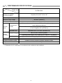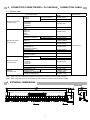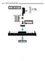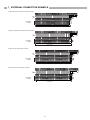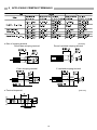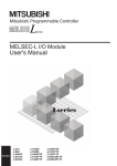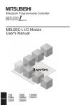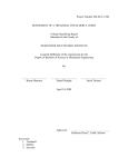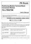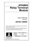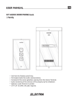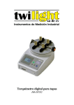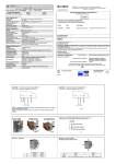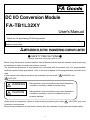
1
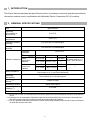
DC I/O Conversion Module FA-TB1L32XY User's Manual Thank you for purchasing FA Goods product. Before using, please read this User’s Manual and the relevant manuals carefully to ensure correct use. SAFETY PRECAUTIONS (Always read these precautions prior to use.) Before using this product, please read this User’s Manual and the relevant manuals carefully and pay full attention to safety to handle the product correctly. The precautions presented in this manual are concerned with this product only. For programmable controller system safety precautions, refer to the User’s Manual of the programmable controller to be used. In this manual, the safety precautions are classified into two levels: " WARNING" and " CAUTION". WARNING Indicates that incorrect handling may cause hazardous conditions, resulting in death or severe injury. CAUTION Indicates that incorrect handling may cause hazardous conditions, resulting in minor or moderate injury or property damage. Under some circumstances, failure to observe the precautions given under " CAUTION" may lead to serious consequences. Observe the precautions of both levels because they are important for personal and system safety. 1 [Design Precautions] WARNING Configure safety circuits external to the programmable controller to ensure that the entire system operates safely even when a fault occurs in the external power supply or the programmable controller, this product. Failure to do so may result in an accident due to an incorrect output or malfunction. (1) Configure external safety circuits, such as an emergency stop circuit, protection circuit, and protective interlock circuit for forward/reverse operation or upper/lower limit positioning. Configure a circuit so that the programmable controller is turned on first and then the external power supply. If the external power supply is turned on first, an accident may occur due to an incorrect output or malfunction. [Design Precautions] CAUTION Do not install the control lines or communication cables together with the main circuit lines or power cables. Keep a distance of 100mm (3.94 inches) or more between them. Failure to do so may result in malfunction due to noise. [Installation Precautions] WARNING Shut off the external power supply (all phases) before installation. Failure to do so may result in electric shock. [Installation Precautions] CAUTION Use the programmable controller in an environment that meets the general specifications in this User’s Manual. Failure to do so may result in electric shock, fire, malfunction, or damage to or deterioration of the product. Securely fix the module with a DIN rail or mounting screws. Incorrect mounting may cause malfunction, failure or drop of the module. When using this product in an environment of frequent vibrations, fix the module with a screw. Tighten the screw within the specified torque range. Undertightening can cause drop of the screw, short circuit or malfunction. Overtightening can damage the screw and/or module, resulting in drop, short circuit, or malfunction. Shut off the external power supply for the system in all phases before mounting or removing the module. Failure to do so may result in damage to, malfunction, or failure of the product. Do not directly touch any conductive parts and electronic components of this product. Doing so can cause malfunction or failure of the product. 2 [Wiring Precautions] WARNING Shut off the external power supply for the system in all phases before installation and wiring. After wiring, attach the included terminal cover to the module before turning it on for operation. Failure to do so may result in electric shock. [Wiring Precautions] CAUTION Use applicable solderless terminals and tighten them within the specified torque range. If any spade solderless terminal is used, it may be disconnected when the terminal screw comes loose, resulting in failure. Check the rated voltage and terminal layout before wiring to the module, and connect the cables correctly. Connecting a power supply with a different voltage rating or incorrect wiring may cause a fire or failure. Do not install the control lines or communication cables together with the main circuit lines or power cables. Keep a distance of 100mm (3.94 inches) or more between them. Failure to do so may result in malfunction due to noise. Place the cables in a duct or clamp them. If not, dangling cables may swing or inadvertently be pulled, resulting in damage to the module or cables or malfunction due to poor connection. Tighten the terminal screw within the specified torque range. Undertightening can cause short circuit, fire, or malfunction. Overtightening can damage the screw and/or module, resulting in drop, short circuit, or malfunction. Tighten the connector screws within the specified torque range. Undertightening can cause short circuit, fire, or malfunction. Overtightening can damage the screw and/or module, resulting in drop, short circuit, fire, or malfunction. Install the connector to the module securely. Failure to do so may cause malfunction. When disconnecting the cable from the module, do not pull the cable by the cable part. For a cable with connector, hold the connector by hand and pull it out. For a cable connected to a terminal block, loosen the terminal block screws first before removing the cable. Failure to do so may result in malfunction and damage to the module or cable. Before connecting the cables, check the type of interface to be connected. Connecting or erroneous wiring to the wrong interface may cause failure to the module and external devices. Prevent foreign matter such as dust or wire chips from entering the module. Such foreign matter can cause a fire, failure, or malfunction. This product must be installed to control panels. Connect the main power supply to this product in the control panel through a relay terminal block. Wiring and replacement of a this product must be performed by qualified service personnel who is familiar with protection against electric shock. When connecting programmable controller, check that the product configuration are correct. The modules may be failure or malfunction if the configuration is incorrect. Use it with power doesn't join the connector of this product. Failure or disconnection may cause malfunction. 3 [Startup and Maintenance Precautions] WARNING Do not touch any terminal while power is on. Doing so will cause electric shock or malfunction. Shut off the external power supply for the system in all phases before cleaning the module or retightening the terminal screws, connector screws, or module fixing screws. Failure to do so may result in electric shock or cause the module to fail or malfunction. Undertightening can cause drop of the screw, short circuit or malfunction. Overtightening can damage the screw and/or module, resulting in drop, short circuit, or malfunction. [Startup and Maintenance Precautions] CAUTION Do not disassemble or modify the modules. Doing so may cause failure, malfunction, injury, or a fire. Use any radio communication device such as a cellular phone or PHS (Personal Handy phone System) more than 25cm (9.85 inches) away in all directions from the programmable controller, this product. Failure to do so may cause malfunction. Shut off the external power supply for the system in all phases before mounting or removing the module. Failure to do so may cause the module to fail or malfunction or damage. After the first use of the product, do not mount/remove the module, and the cable more than 50 times (IEC 61131-2 compliant) respectively. Exceeding the limit of 50 times may cause malfunction. Startup and maintenance of a control panel must be performed by qualified maintenance personnel with knowledge of protection against electric shock. Lock the control panel so that only qualified maintenance personnel can operate it. Before handling the module, touch a grounded metal object to discharge the static electricity from the human body. Failure to do so may cause the module to fail or malfunction. [Disposal Precautions] CAUTION When disposing of this product, treat it as industrial waste. [Transportation Precautions] CAUTION The shock that exceeds the range of the general specification during transportation must avoid this product for the precision instrument. Doing so results in the risk of failure. 4 1.INTRODUCTION This User’s Manual describes the specifications and so on between connectors and the terminal block conversion modules used in combination with Mitsubishi Electric Corporation DC I/O modules. 2.GENERAL SPECIFICATIONS Item Specifications Operating Surrounding air temperature 0 to 55°C Storage ambient temperature -25 to 75°C Operating ambient humidity 5 to 95% RH, no condensation Storage ambient humidity 5 to 95% RH, no condensation Compliant standards Under Vibration resistance intermittent vibration Under continuous vibration Shock resistance IEC61131-2 Frequency Acceleration Amplitude 10 to 57Hz ― 0.075mm 2 57 to 150Hz 9.8m/s (1G) ― 10 to 57Hz ― 0.035mm 57 to 150Hz 4.9m/s2 (0.5G) Sweep count 10 times each in X, Y, and Z axis directions ― ― Conforms to IEC61131-2 (147m/s2 (15G), 3 times each in X, Y, and Z axis directions) Operating atmosphere There should be no corrosive gases. Operating altitude (* 1) 2,000m or lower Installation location Inside control panel Overvoltage category (* 2) II or lower Pollution level (* 3) 2 or lower * 1: Do not use or store in a pressurized environment greater than the atmospheric pressure at an altitude of 0m. * 2: Indicates how an assumption has been made on the point at which the devices are connected from the public power grid to the machinery and equipment inside the facilities. * 3: This is a guideline indicating the extent to which conducting substances are found in the environment in which the devices are used. 5 3.PERFORMANCE SPECIFICATIONS Model name FA-TB1L32XY Item Number of I/O points I/O device numbers 32 points, X0 to X1F / Y0 to Y1F Rated voltage 24VDC (CLASS 2) Maximum usage voltage Maximum usage current Terminal block 28.8VDC (CLASS 2) (* 1) Terminal block Screws Applicable wire Module mounting Mounting screws DIN rail Signal: 1A, Common: 2A M3.5 screw, Number of terminals:34P, Pitch of 8mm(9mm only center), screw holding mechanism Terminal screw tightening torque range: 70 to 110N・cm (7.2 to 11.2kgf•cm, 6.2 to 9.7lbf・in) Applicable wire: 0.3 to 2mm2(AWG24 to 14) M4 × 0.7mm × 12mm or greater Tightening torque range: 78 to 118N·cm (8 to 12kgf·cm, 7 to 10lbf·in) Applicable DIN rail: TH35-7.5Fe, TH35-7.5Al (conform to IEC60715) Dielectric withstand voltage 500VAC for 1 minute Insulation resistance (initial) 100MΩ or more by 500VDC insulation resistance tester Weight About 230g * 1: Evaluation for UL certification is conducted under resistance load conditions. 6 4.CONNECTED TARGET MODEL / PLC MODULE,CONNECTION CABLE 4-1. Selection table Connection Cable Model PLC Module Model RX41C4 RX42C4 MELSEC iQ-R Series connector type MELSEC-Q Series connector type MELSEC-L Series connector type CC-Link connector type RY41NT2P RY42NT2P RY41PT1P RY42PT1P RH42C4NT2P QX41 QX41-S1 QX41-S2 QX42 QX42-S1 QX71(Note 1),(Note 2) QX72(Note 1),(Note 2) QX81 QX81-S2 QX82 QX82-S1 QY41P(Note 2) QY42P(Note 2) QY71(Note 1),(Note 2) QY81P(Note 2) QY82P(Note 2) QH42P QX41Y41P(Note 2) LX41C4 LX42C4 LY41NT1P LY42NT1P LY41PT1P LY42PT1P LH42C4NT1P LH42C4PT1P AJ65SBTCF1-32D AJ65BTC1-32D AJ65SBTCF1-32T(Note 2) AJ65BTC1-32T(Note 2) At positive common FA-CBL**FMV At negative common FA-CBL**FMVE Module Model FA-CBL**FMV refer to RX41C4, RY41NT2P FA-CBL**FMV At positive common At negative common FA-CBL**FMV FA-CBL**FMVE FA-CBL**DMFX FA-CBL**FMVE FA-TB1L32XY FA-CBL**FMV FA-CBL**DMFY FA-CBL**FMV refer to QX41, QY41P At positive common At negative common FA-CBL**FMV FA-CBL**FMVE FA-CBL**FMV refer to LX41C4, LY41NT1 refer to LX41C4, LY41P1 At positive common FA-CBL**FMH FA-FCBL**FMH FA-CBL**FMH FA-FCBL**FMH Note 1: When using with 5VDC power supplies, connect 5VDC to 24VDC on the conversion module. Note 2: When using with 12VDC power supplies, connect 12VDC to 24VDC on the conversion module. 5.EXTERNAL DIMENSIONS [Unit: mm] 7 6.INSTALLATION METHOD 8 7.EXTERNAL CONNECTION EXAMPLE (1) When the positive common input module connection Connection example sensor(1 wiring) (2) When the negative common input module connection Connection example sensor(1 wiring) (3) When the sink output module connection Connection example Load(1 wiring) (4) When the source output module connection Connection example Load(1 wiring) 9 8.APPLICABLE CRIMPING TERMINALS ● Size of crimping terminal Round bare crimping terminal [Unit:mm] Round insulated crimping terminal Y bare crimping terminal Y insulated crimping terminal ● Terminal trapezoid [Unit:mm] 10 FOR YOUR SAFETY This product has been manufactured as a general-purpose product for general industry applications, etc. The product is not intended for use in devices or systems used under conditions in which human life could be greatly affected. When considering application of this product to special applications, such as nuclear power, electrical power, aerospace, medical, or manned transport devices or systems, contact our sales service desk. Although this product was manufactured under a strict quality management system, the product shall be systematically provided with backup and fail-safe functions when applied to equipment that may lead to a major accident or damage in the unlikely event any failure or defect should occur in the product. 1-13-5 Kudankita, Chiyoda-ku, Tokyo, Japan 102-0073 Homepage URL: http://www.mee.co.jp/ During product use, be sure to ensure safety in the unlikely event failure occurs. Mitsubishi Electric Engineering assumes no responsibility whatsoever for any secondary damage caused by the failure of this product. 50D-FA9010-140 Information such as specifications is subject to change without notice. Developed August 2014 11