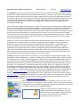
1
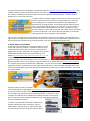
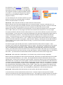
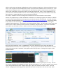
The software is a free download. It is a graphical
environment very similar to Scratch. The program
illustrated can be sent to Crumble via the USB cable –
use ‘Program’ and select `Program Crumble and Run’
to transfer it. Use the green triangle and red square
buttons to start and stop the program. Save the
program as `Blinky’.
For this example you do not need to attach any Inputs,
Outputs or Power to the Crumble board. It will just
flash its red LED for Motor 1 on and off.
Exercise 6.1 Add commands for Motor 2 to blink both the on-board LEDs.
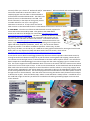
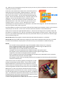
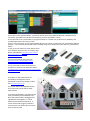
Now we will use one of the LEDs supplied with kit as an external output. Connect a red lead to the +ve
Power Out at the top right of the Crumble controller and to the longer leg of the LED. Connect a black lead
from its shorter leg to the Input/Output connector marked A on the left side of the Crumble.
Replace the two motor commands in the program with ‘set A HI’ boxes and change the ‘HI’ in the second
one to ‘LOW’. When you run the program you will have to look hard at the LED as it is not very bright!
The power provided to the board via the USB connector is very low and not sufficient to power most of the
external outputs. So the next step is to open the black battery box and install 3 AA batteries. Notice there is
a small on/off switch on the box. This will provide the power needed to switch outputs like LEDs and
motors. It will also allow you to run the stored program on Crumble when you disconnect it from the
computer. Connect it to the Power In + and – contacts on the top left of the board. Now start the program
again and the LED should flash very brightly. While the LED is flashing, carefully pull out the USB connection
to the Crumble. The program should continue running – so you have now created an autonomous device.
Save the program.
The starter kit gives you two LEDs, two motors, a Sparkle LED board, and a buzzer as outputs. It also
provides a micro-switch and a light dependent resistor as inputs. Now we have enough power on the board
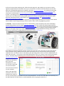
to drive the outputs we can test each of them. Open the `Blinky’ program again. Disconnect the external
LED. Use a black lead to connect the –ve output for Motor 1 to one of the tiny connectors on one of the
motors, and a red lead to connect the other to the +ve output on Crumble. Now when you run the program
you should see and hear the motor starting, running and stopping. Switch the ON/OFF button on the battery
box to OFF – you should see the on-board LED continue to flash, but the motor will no longer work.
Exercise 6.2 Add commands to make Motor 1 run forward, stop, run back and stop, repeatedly.
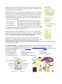
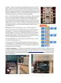
Now we will use the Sparkle unit with its multi-coloured LED. Disconnect any leads attached to the Crumble
except the USB and the Battery + and – leads. On the Sparkle find the hole marked with D and an arrow
pointing away. Connect this to the D port on the Crumble. Connect the hole on its left on the Sparkle with a
black lead to the –ve power out on the Crumble. Connect the last hole on the Sparkle with a red lead to the
+ve power out on the Crumble. Use the `Blinky’ program again, but this time use `set sparkle 0 to’ and select
the colour red from the palette to replace `motor 1 FORWARD at 100%’. Then use `set sparkle to’ and select
the colour black from the palette to replace ‘motor 1 STOP’. When you run the program the Sparkle’s LED
will switch to red, then off repeatedly. Save the program. With additional Sparkle units you can wire them
in a chain using three leads at a time. The next Sparkle unit will be unit 1, the next unit 2 and so on.
Exercise 6.3 Make Sparkle flash alternatively red, then yellow and then green repeatedly.
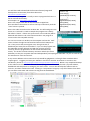
To test the buzzer connect its black lead to either of the –ve power outputs at the top of the Crumble.
Connect its red lead to one of the lettered outputs such as C. The program to switch the buzzer on and off is
exactly the same as the `Blinky’ program but with the Motor commands replaced with `Set C HI’ and `Set C