1
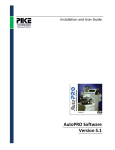
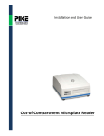
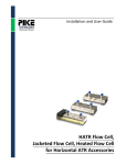
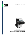
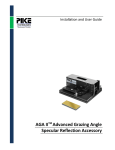
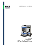
Installation and User Guide
Six Inch Vertical Wafer
Transmission Accessory
The information in this publication is provided for reference only. All
information contained in this publication is believed to be correct and
complete. PIKE Technologies, Inc. shall not be liable for errors contained herein
nor for incidental or consequential damages in connection with the furnishing,
performance, or use of this material. All product specifications, as well as the
information contained in this publication, are subject to change without notice.
This publication may contain or reference information and products protected
by copyrights or patents and does not convey any license under the patent
rights of PIKE Technologies, Inc. nor the rights of others. PIKE Technologies, Inc.
does not assume any liability arising out of any infringements of patents or
other rights of third parties.
This document contains confidential or proprietary information of PIKE
Technologies, Inc. Neither this document nor the information herein is to be
reproduced, distributed, used or disclosed, either in whole or in part, except as
specifically authorized by PIKE Technologies, Inc.
PIKE Technologies, Inc. makes no warranty of any kind with regard to this
material including, but not limited to, the implied warranties of merchantability
and fitness for a particular purpose.
Copyright 1991-2013 by PIKE Technologies, Inc., Madison, WI 53719. Printed in
the United States of America. All world rights reserved. No part of this
publication may be stored in a retrieval system, transmitted, or reproduced in
any way, including but not limited to, photocopy, photograph, magnetic or
other record, without the prior written permission of PIKE Technologies, Inc.
Address Comments to:
PIKE Technologies, Inc.
6125 Cottonwood Drive
Madison, WI 53719
Phone
Fax
E-mail
Web Site
Jan. 1, 2013
PN 350-073601-01
(608) 274-2721
(608) 274-0103
[email protected]
www.piketech.com
Contents
Introduction
Unpacking Your Accessory
Packing List
Installation and Use
Removing the Holder from the Accessory
Inserting a Wafer
Initial Alignment
Linear Orientation to the Beam
Installing the Software
Installing the AutoPRO Motor Controller
Connecting the Motor Controller to Your
Computer
Correct Cabling Procedure
Starting AutoPRO
It’s Your First Time
AutoPRO Overview
AutoPRO Control
How to Use Help
Status
Init.exe, First,exe…
PN 350-073601-01
1
2
2
3
3
3
4
4
5
6
6
7
7
8
9
9
12
12
12
Introduction
The Vertical Wafer Accessory has been designed to mount a wafer in the beam of an FTIR spectrometer
to allow manual or automatic mapping of the transmittance spectrum of the wafer. The accessory has
two major parts, the drive mechanism and the ring.
The ring is placed into the drive mechanism and may be rotated through 360 degrees and translated
through 3 inches to produce an R-Theta motion.
The tolerance of the diameter of the wafer that can be mounted conforms to SEMI standards.
Orientation of the wafer with respect to the angle scale is left to the user’s discretion. It may be useful
to mark the clamp side of the ring with respect to the angular scale so that the wafer flat may have a
repeatable position with respect to the scale.
The Vertical Wafer Accessory is mounted onto a standard sample compartment baseplate perpendicular
to the beam. The entire baseplate and accessory can then be secured to the instruments sample
compartment.
Wafer Ring
Drive Mechanism
Figure 1. 6 Inch Vertical Wafer Accessory
PN 350-073601-01
P a g e |1
Unpacking Your Accessory
In order for you to quickly verify receipt of your accessory, we have included a packing list. Please
inspect the package carefully.
Packing List
Manual Wafer Holder
Vertical Wafer Accessory Manual
Vertical Wafer Accessory
6 Inch Wafer Ring
PN 350-073601
PN 073-16XX
PN 073-3600
Quantity 1
Quantity 1
Quantity 1
Vertical Wafer Accessory Manual
AutoPRO Manual and Software
Motorized Vertical Wafer Accy
PN 350-073601
PN 350-000070
PN 073-26XX
Quantity 1
Quantity 1
Quantity 1
Motor Controller
6 Inch Wafer Ring
Power Cables
Quantity 1
PN 073-3600
Quantity 1 set
Automated Wafer Holder
Quantity 1
PN 350-073601-01
P a g e |2
Idler Pulley
Installation and Use
Removing the Holder from the Accessory
Gear Drive
Perform the following steps:
1. Grasp the holder firmly between the top idler pulley and
the tension idler.
2. Gently push in a horizontal plane toward the instrument.
Tension Idler
3. When the ring has cleared the idler pulley and gear driver slightly twist the rear of the holder
to the right.
4. Pull the holder back horizontally until the tension idler has recoiled and remove the ring.
Inserting a Wafer
Perform the following steps:
1. Remove the wafer holding ring from its mount and place it on a flat surface.
2. Rotate the three clamps so that the flats on the clamps are facing inwards.
3. Place a wafer in the ring. The wafer will rest on the three DelrinTM surfaces beneath the clamps.
4. Rotationally orient the flat on the wafer to the desired position with respect to the ring. It may be
useful to place a mark on the ring to aid in this positioning.
5. Rotate the wafer clamps through 180 degrees to secure the wafer in place.
Delrin Clamps
PN 350-073601-01
P a g e |3
Initial Alignment
Linear Orientation to the Beam
The Vertical Wafer Accessory has been pre-aligned to the sample baseplate to assure the infrared beam
strikes the center of the wafer and that the maximum travel is allowed in both the linear and rotational
planes. The linear slide has two stops to limit the amount of travel of the slide.
The scale indicator showing the radius distance may be set to zero by loosening the two screws
fastening the indicator. Align the scale indicator to the zero mark and secure the mounting screws.
Scale Indicator
Indicator Mounting Screws
PN 350-073601-01
P a g e |4
Installing the Software
NOTE: Always install the software first before plugging in the motion control
unit. If the controller is plugged in before the software has been installed the
PIKE USB device driver may need to be updated. Please refer to Appendix B of
the AutoPRO5 manual.
Step 1:
Insert the CD into the drive of your computer.
Step 2:
From the START menu, select Run. The Run dialog box will appear to enter a filename.
Enter either: X:setup.exe or “browse” to the Disk Directory and select setup.exe.
A setup dialog box will appear for a few moments while the installation program checks for available
memory and configuration.
The AutoPRO Setup dialog box will appear:
Choose to use the default path select
Enter
OR
Choose to enter an alternative path and then select
Enter
OR
Choose to exit Setup by selecting
EXIT
The software will be copied. The source and destination files and percentage of completed task are
displayed.
A dialog box will appear when the program has been loaded. Click on the OK box to complete the
installation.
Now the motion control unit can be plugged in. Windows Plug and Play will detect the new device being
plugged in and prompt you to install a driver for it. Please refer to the AutoPRO5 manual for more
details.
PN 350-073601-01
P a g e |5
Installing the AutoPRO Motor Controller
The motion control electronics interface the Vertical Wafer Accessory to your computer. Commands are
sent to this electronics unit using a USB cable. A 15-pin accessory cable is used to connect this unit to
the accessory.
Connecting the Motor Controller to Your Computer
The power supply for the motor controller is self-adjusting and can be used in most locations. Please
read the labels on the rear of the motor controller before attempting to connect the system.
The power for the motor controller should always be turned off when attaching the cables.
Figure 10. Motor controller rear panel
PN 350-073601-01
P a g e |6
Correct Cabling Procedure
Computer to Motor Controller
USB Cable
Computer
15-Pin Male/Male Accessory Cable
PIKE Motor Controller to Accessory
Motor Controller
PIKE Accessory
Figure 11. Correct cabling procedure
•
The accessory port of the motor controller should be connected to the accessory through the
6 foot, male-to-male 15-pin cable provided.
•
Connect the USB cable from the controller to the PC.
Starting AutoPRO
There are several ways in which to run AutoPRO control. Follow the steps below in order to start
AutoPRO Control as a stand-alone application:
1.
Click the start button
2.
Point to Programs
3.
Point to the AutoPRO5 folder
4.
Click on the AutoPRO program
The program will be run, and will be displayed in the lower left hand corner of the display. Note that
AutoPRO requires that your computer system be set up with a screen resolution of at least 800x600.
PN 350-073601-01
P a g e |7
It’s Your First Time
When you start AutoPRO for the first time, the software does not know which accessory you have and
you will be asked to configure the software. The dialog below will be shown.
When you click OK, the Accessory Setup page will be displayed.
In order to configure the software to work with your accessory, click the button next to the accessory
description. Click on 6” holder and ensure DEMO MODE is OFF. Click OK.
PN 350-073601-01
P a g e |8
AutoPRO Overview
AutoPRO is a Windows based automation software program for use with PIKE automated accessories
and the AutoPRO motion controller. With this software package a range of automated accessories may
be programmed and operated in conjunction with most Windows based FTIR software packages. Several
programs comprise the complete software package, but the following two programs are central to the
function of the software and will be introduced briefly here.
AutoPRO Control
This program contains the tools required to operate your automated accessory.
The AutoPRO control panel contains the following major functions:
•
Setup Bench - Basic parameters for data collection (number of scans, resolution, etc.) may be
defined and stored to a file.
PN 350-073601-01
P a g e |9
•
Setup Accessory - This function allows selection of the actual accessory used with the spectrometer,
computer/accessory communication test, and basic accessory setup. Select 6 inch Holder.
•
Setup Experiment - Macros and executable files can be integrated into the autosampler routine.
This function also allows special handling of multiple filenames and provides different security
options.
PN 350-073601-01
P a g e | 10
•
Program Motions - A series of samples may be defined and stored to a file. This file may be
subsequently used to move your accessory while collecting data from your spectrometer.
•
Load and Unload - The accessory stage may be moved to an unload position to simplify the insertion
of new samples.
PN 350-073601-01
P a g e | 11
How to Use Help
Choose Help from the menu, or press F1 on the keyboard.
•
•
•
Index - Displays an index of Help topics including menus, commands, and shortcuts.
Using Help - Provides information on how to use Windows Help.
About - Provides specific information regarding the version of AutoPRO and current system
information.
Status
The status of the accessory at any time is displayed. This includes the position of the accessory, the
current status of the motors and a thumbnail view of the file being used for programming the motion.
These and all other functions are described fully in the AutoPRO manual.
Init.exe, First.exe…
These are programs which may be inserted into an FTIR macro. With these programs the basic functions
required to run the accessory may be accessed from within the macro. While the software is running a
small AutoPRO status box is displayed in the lower right hand corner.
More details of how to use this and other .exe files available in the AutoPRO software are given in the
AutoPRO User’s Manual.
PN 350-073601-01
P a g e | 12
6125 Cottonwood Drive · Madison, WI 53719-5120 · (608) 274-2721 (TEL) · (608) 274-0103 (FAX)
[email protected] · www.piketech.com