1
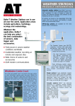
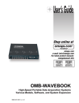
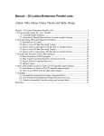
QUICK START
LogBook/300
Stand-alone, Intelligent PC-based,
Data Acquisition System
LogBook/300
461-0940 rev 3.0
*324586C-01*
324586C-01
Measurement Computing
10 Commerce Way
Norton, MA 02766
(508) 946-5100
Fax: (508) 946-9500
[email protected]
www.mccdaq.com
LogBook/300
Quick Start
Before you get started
Software Installation …… QS300-2
Verify that you have the following items.
Hardware Connection …… QS300-2
Hardware Configuration …… QS300-4
LogBook/300 Device Configuration …… QS300-5
Testing the Hardware …… QS300-7
Acquisition Configuration …… QS300-8
A Note about Calibration …… QS300-8
•
•
•
•
•
•
•
LogBook/300
TR-40U Power Supply
Serial/Parallel Patch Cable, or PC Card Reader
PC with ECP (Enhanced Capabilities Port)
Data Acquisition CD
Monitor: SVGA, 1024 x 768 screen resolution
Windows 2000 SP4 and Windows XP users:
PC with Intel™ Pentium [or equivalent], 1 GHz;
128 MB memory; 10 GB disk space
• Windows Vista users:
PC must be Windows Vista Premium Ready
IMPORTANT! Software must be installed first!
Software Installation
1.
Close all running applications on the host PC.
2.
Remove previous version drivers, if present. You can do this through Microsoft’s Add/Remove Programs
feature.
3.
Insert the Data Acquisition CD (8.1.2 or higher) into your CD-ROM drive and wait for the PC to auto-run. An
Opening Screen will appear. If AutoRun is disabled: (a) right click Windows Start menu, (b) select Explore; and
(c) double-click MasterSetup.exe. As an alternative to using the CD, you can download software from:
www.mccdaq.com
4.
Click the <ENTER SETUP> button.
Note: If you are downloading software from our website, follow instructions provided there.
5.
From the hardware selection screen, select your data acquisition device then follow the on-screen instructions.
Note: To enable all LogView features:
(a) From LogView’s main window, open the File pull-down menu,
(b) select Authorization,
(c) enter ED7B55484273 in the dialog box and apply the code.
Hardware Connection
WARNING
Electric shock hazard. Turn off power to all system-connected devices prior to connecting
or disconnecting cables, or setting hardware configurations. Failure to do so could result
in electric shock or death, and equipment damage, even under low-voltage conditions.
When using LogBook/300 in attached mode, the PC-Card [in LogBook/300] must already
have the file logbook.sys. Otherwise, LogView cannot communicate with LogBook/300,
and LogBook/300 will appear dead.
QS300-2
LogBook/300 Quick Start Guide
Reference Notes:
Depending on the nature of your LogBook system, you may find one or more of the following
references to the LogBook User’s Manual PDF helpful. The PDF manual is included on the Data
Acquisition CD and is also available on our web-site.
o
o
o
o
For system block diagrams and operational overviews, refer to Chapter 1 of the PDF.
For information on system expansion and calculating system power, refer to Chapter 4 and to
the DBK Basics section.
For information regarding LBK options, refer to Chapter 5.
For specific DBK card information, refer to the DBK Options Manual PDF.
The following hardware-connection figure and procedure are generic; details vary with system complexity.
Note: Other power options are discussed in
the DBK Basics section of this
manual.
After verifying that all equipment power is off, hardware connection typically proceeds as follows.
Refer to the previous figure as needed.
1.
Connect LogBook/300 to PC. There are four ways for LogBook/300 to communicate with the host
PC. These are: parallel port, serial port to serial port, serial port to USB, and manual transportation
of the PC-Card. Note that the parallel port method is represented in the previous figure.
a)
Parallel port – If using the parallel port, connect a DB25male to DB25female parallel cable
[e.g., CA-35-2 or CA-35-6 (2ft. or 6ft. respectively)] to PARALLEL PORT on LogBook/300, and to the
corresponding parallel port on the host PC. When this method is used, the PC must be set to the ECP
mode. See ECP Parallel Port, page QS300-6 for additional information.
b)
Serial port to serial port – If using the serial port, use a null modem serial cable (CA-47) to connect the
DB9 SERIAL PORT on LogBook/300 to the corresponding DB9 serial port on the host PC.
c)
Serial port to USB port - Requires an adapter kit. To connect the LogBook to a USB port you will need a
RS-232 to USB Interface Adapter Kit p/n CA-232-USB-KIT (available from MCC). Refer to the
associated Quick Start document (QS RS-232_to_USB_Interface.pdf) for a list of the kit’s contents and for
RS-232 to USB conversion instructions. The pdf is included on Data Acquisition CD (rev 8.1.2 and
higher).
d)
PC-Card – With PC-Card communication, LogBook/300 does not require a connection to the computer, as
communication is accomplished via the PC-Card. To provide the PC-Card with the correct configuration
file, it must be configured from the PC, through LogView. After the PC-Card is configured, it is inserted
into LogBook’s PC-Card slot, located behind the front panel door.
Reference Note:
Information pertaining to PC-Cards can be found in chapter 1 and in the LogView section of the
LogBook User’s Manual PDF.
LogBook/300 Quick Start Guide
QS300-3
2.
Connect the LogBook/300 to the DBK cards and modules. Most of the analog DBKs connect to P1
on the rear panel; the digital DBKs generally connect to P2.
Reference Note:
For DBK card related information, refer to the DBK Options Manual PDF. The document is
included on the Data Acquisition CD and is also available on our web-site.
Note: The CA-37-x cable can daisy-chain several DBKs including the DBK41, which has a built-in
P1 bus connection for 10 DBK cards. The x in the cable part number refers to the number of
devices that can be connected to a device, for example: a CA-37-1 cable has two DB-37
connectors, one for connecting to the LogBook and another for connecting the card or
module. Pinouts for P1, P2, and P3 are included in the System Expansion chapter.
CAUTION
For analog signal inputs via P1, do not exceed -35 VDC or +45 VDC.
Exceeding these limits could result in equipment damage.
3.
Connect DBK(s) to transducer(s). Follow instructions for the specific DBK(s) as described in the
DBK Option Cards & Modules User’s Manual, as well as instructions for the applicable transducers.
4.
Connect the LogBook/300 to a suitable power source such as the
included AC-to-DC adapter or the optional DBK34A. DC
power sources such as a car batteries must supply 10 to 45 VDC
and use the correct DIN5 pinout (see figure). A locking DIN5
connector assures a secure power connection for applications
subject to vibration or thermal stress.
5.
Optional - Just one cable connects between the LBK1
(via RJ-11 connector) and the LogBook/300 (via a DB9 connector). The standard cable is 6 feet
long. An optional 25 foot cable is available. See chapter 5 of the LogBook User’s Manual PDF for
details regarding the installation of LBK1.
Hardware Configuration
Reference Note:
Refer to the device-specific sections of the LBK Options chapter of the user’s manual and to
the DBK Options Manual PDFs for information regarding these devices. Note that certain
DBK options require manual configuration.
LogBook/300's top cover does not need to be removed, except to add or remove an LBK option, or to
replace the fuse.
Most LogBook/300 configuration is done via software as described in the LogBook/300 Device
Configuration section of this document (page QS300-5). LogBook/300 configuration does not require the
setting of jumpers or switches, unless the RS-485 communication option is being used.
QS300-4
LogBook/300 Quick Start Guide
Upon completing the software installation, continue with LogBook/300 Device Configuration.
LogBook/300 Device Configuration
A configuration utility is supplied via a control panel applet. The LogBook Configuration applet allows
you to add a device, remove a device, or change existing configuration settings. From this same window,
you can also access a built-in utility to test the connected device for current setup and performance.
LogBook Configuration can be found in the Microsoft Windows Control Panel. The Control Panel can be
navigated to from Windows desktop Start button as follows:
Start ⇒ Settings ⇒ Control Panel
You can enter LogBook Configuration during driver installation or whenever you wish to add, remove or
change device configuration settings.
The first configuration window will display configured devices in the Device Inventory field based on the
port they’re connected to. Devices are represented by an icon and text, e.g., LogBook (LPT1), as can be
seen in the following figure. If no devices are configured, the device inventory field will remain blank.
The figure shows the first and second configuration windows overlapped.
LogBook Configuration Windows
The four buttons across the bottom of the first configuration window (previous figure) are used as follows:
•
Properties. Configuration settings for a device can be changed or modified from the corresponding
properties window. To do so, double-click the device icon or single-click the device and then singleclick the Properties button. The second configuration window will appear for the selected device as
shown in the previous figure.
•
Add Device. The Add Device button is used to add a device configuration whenever a new device is
added to the system. LogView cannot recognize a device unless listed in the configuration window.
•
Remove. The Remove button is used to remove a device from the configuration. A device may be
removed if it is no longer installed or if the device’s configuration no longer applies.
•
Close. The Close button may be used at any time to exit the LogBook Configuration applet.
The second configuration window displays the properties for the selected LogBook/300. Fields include:
LogBook/300 Quick Start Guide
QS300-5
•
Device Name is displayed with the default name, numbered successively as configured. This field can
be changed to any descriptive name as desired.
•
Connection Type can be serial or parallel port.
•
Device Connection specifies the port name.
•
Protocol is used to set the parallel port protocol (ECP only) or serial protocol (RS-232 or RS-485).
•
Device Timeout specifies the number of seconds LogView will be wait for a LogBook response before
displaying an error condition.
ECP Parallel Port
To use parallel port communication with an attached LogBook/300, your PC must
support the ECP protocol AND be set in the ECP mode.
The majority of today’s PCs support the Enhanced Computer Port protocol (ECP). If your computer does
not support ECP, you can communicate with the LogBook/300 via the RS-232 serial port, or you can add an
ECP-compatible ISA board or PC-Card parallel port. Setting the PC to ECP mode varies with different
computers. On some computers, you can enter the BIOS Setup utility from Windows Settings or during
startup by pressing the F1 function key. The Parallel Port Mode property can be found under the Peripheral
Configuration group menu item. If necessary, consult your PC’s documentation or your PC’s manufacturer.
To ensure ECP compatibility after proper setup, use the Test Hardware utility
(described on page QS300-7). Before testing, make sure LogBook/300 is properly
connected, powered on, and that the Parallel Port Mode is set to ECP (in BIOS Setup).
CAUTION
Making errors in BIOS Setup can disrupt your system’s operation. If test hardware
indicates a problem and you have inadequate experience with the BIOS Setup utility,
consult your System Administrator or other qualified individual.
QS300-6
LogBook/300 Quick Start Guide
Serial Port
If the selected device is connected to a serial port the properties window will include the fields shown in the
following figure. Baud rate can be set from 1200 to 115200 bits per second (default 9600). When all fields
have been changed to the desired settings, you can click on one of the following options:
•
Apply to store the device configuration. Parameters are not locked in until you click the Apply button.
If you make changes and don’t click Apply, clicking the Test button in Test Hardware will yield
unexpected errors.
•
OK to store the configuration and exit the current property screen.
•
Cancel to exit the current screen without storing any changes.
•
Test Hardware to test the current device.
LogBook Properties Tab
Test Hardware Tab
Testing the Hardware
Before testing LogBook/300:
(a) Verify the device has been properly installed
(b) Make sure the communication cable (serial or parallel) is firmly in place to the proper ports.
(c) Verify the device is powered-on.
Testing the LogBook/300 device might cause the system to hang. If test results are not
displayed within 30 seconds, or if the system does not respond properly do the following:
• Reboot the system.
• Upon power-up, re-enter the LogBook Configuration.
• Ensure the configuration settings are correct. Change the settings as applicable.
To begin the test, click the Test button. Test results should be displayed within a few seconds.
Test results indicate if the device is online (properly connected, powered on and ready to transfer the data)
or offline. If the device is online, Performance Test will display Download and Upload speed rates. These
rates represent the maximum speed at which downloading and uploading files can be performed. Actual
transfer time will depend on channel configuration and the size of the transfer.
LogBook/300 Quick Start Guide
QS300-7
Acquisition Configuration
An acquisition is configured using LogView on a PC and then stored as an acquisition setup file on a
PC-Card. The PC-Card may be in an attached LogBook/300 or in the PC to be later manually transferred to
an unattached LogBook/300. The system’s DBK cards are listed; the scan sequence is defined; the trigger
conditions are specified, etc.
Reference Note:
Configuring the acquisition is described in the LogView section of the LogBook User’s
Manual PDF, which is included on the Data Acquisition CD and on our web-site.
A Note about Calibration
Calibration is typically performed automatically through LogView software; however, some DBKs may
require manual calibration. LogView’s 2-point calibration fine-tunes the reading’s slope and offset error
(mx+b). DBKs working with non-linear sensors typically condition/convert the reading to a linear form.
Otherwise, a non-linear analog input signal is difficult to read accurately. Careful use of the calculated
channels may yield usable approximations in simple, limited-range conditions.
Reference Notes:
• An example of 2-point calibration is provided under the Procedures heading in the
LogView section of the manual.
• For information on calibrating the DBK16 and the DBK43A, refer to the
DBK Option Cards and Modules User’s Manual (p/n 457-0905).
Measurement Computing Corp., 10 Commerce Way., Norton, MA 02766
phone: (508) 946-5100; e-mail: [email protected]; www.mccdaq.com
QS300-8
LogBook/300 Quick Start Guide