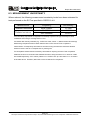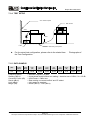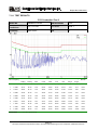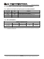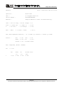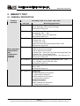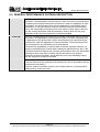
1
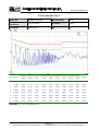
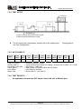
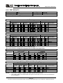
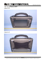
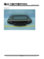
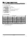
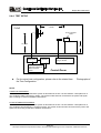
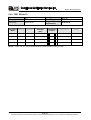
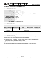
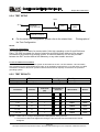
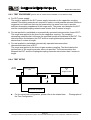
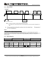
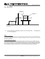
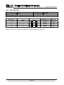
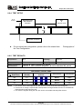
Report No: 81004101-E CE EMC TEST REPORT for 8.4 Rugged Tablet PC MODEL: R08I68M-RTXXXX (X= A~Z, a~z, 0 ~9, Blank or Slash) Test Report Number: 81004101-E Issued for Winmate Communication Inc. 9F, No. 111-6, Shing-De Rd., San-Chung City, Taipei 241, Taiwan, R.O.C. Issued By: Compliance Certification Services Inc. Linkuo Laboratory No. 81-1, Lane 210, Pa-De 2nd Rd., Luchu Hsiang, Taoyuan Shien, (338), Taiwan, R.O.C. TEL: 886-3-324-0332 FAX: 886-3-324-5235 E-Mail: [email protected] Issued Date: October 13, 2008 Note: This report shall not be reproduced except in full, without the written approval of Compliance Certification Services Inc. This document may be altered or revised by Compliance Certification Services Inc. personnel only, and shall be noted in the revision section of the document. The client should not use it to claim product endorsement by TAF, A2LA, NIST or any government agencies. The test results in the report only apply to the tested sample. Page 1 / 63 Report No: 81004101-E Revision History Rev. 00 Issue Date October 13, 2008 Revisions Initial Issue Effect Page ALL Revised By Jill Shiau Page 2 This report shall not be reproduced except in full, without the written approval of Compliance Certification Services. Report No: 81004101-E TABLE OF CONTENTS 1 TEST CERTIFICATION......................................................................................................4 2 TEST RESULT SUMMARY................................................................................................5 3 EUT DESCRIPTION...........................................................................................................6 4 TEST METHODOLOGY.....................................................................................................7 4.1. DECISION OF FINAL TEST MODE....................................................................................7 4.2. EUT SYSTEM OPERATION...............................................................................................7 5 SETUP OF EQUIPMENT UNDER TEST............................................................................8 5.1. DESCRIPTION OF SUPPORT UNITS ...............................................................................8 5.2. CONFIGURATION OF SYSTEM UNDER TEST.................................................................8 6 FACILITIES AND ACCREDITATIONS...............................................................................9 6.1. FACILITIES ........................................................................................................................9 6.2. ACCREDITATIONS ............................................................................................................9 6.3. MEASUREMENT UNCERTAINTY....................................................................................10 7 EMISSION TEST..............................................................................................................11 7.1. CONDUCTED EMISSION MEASUREMENT.................................................................... 11 7.2. CONDUCTED EMISSION MEASUREMENT AT TELECOMMUNICATION PORTS..........16 7.3. RADIATED EMISSION MEASUREMENT.........................................................................19 7.4. HARMONICS CURRENT MEASUREMENT.....................................................................24 7.5. VOLTAGE FLUCTUATION AND FLICKS MEASUREMENT .............................................26 8 IMMUNITY TEST .............................................................................................................31 8.1. GENERAL DESCRIPTION ...............................................................................................31 8.2. GENERAL PERFORMANCE CRITERIA DESCRIPTION .................................................32 8.3. ELECTROSTATIC DISCHARGE (ESD)............................................................................33 8.4. RADIATED, RADIO-FREQUENCY, ELECTROMAGNETIC FIELD (RS)...........................40 8.5. ELECTRICAL FAST TRANSIENT (EFT)...........................................................................44 8.6. SURGE IMMUNITY TEST ................................................................................................46 8.7. CONDUCTED RADIO FREQUENCY DISTURBANCES (CS) ..........................................49 8.8. POWER FREQUENCY MAGNETIC FIELD......................................................................52 8.9. VOLTAGE DIP & VOLTAGE INTERRUPTIONS................................................................55 9 PHOTOGRAPHS OF THE TEST CONFIGURATION.......................................................57 Page 3 This report shall not be reproduced except in full, without the written approval of Compliance Certification Services. Report No: 81004101-E 1 TEST CERTIFICATION Product: 8.4 Rugged Tablet PC Model: R08I68M-RTXXXX (X= A~Z, a~z, 0 ~9, Blank or Slash) Brand: Winmate Applicant: Winmate Communication Inc. 9F, No. 111-6, Shing-De Rd., San-Chung City, Taipei 241, Taiwan, R.O.C. Manufacturer: Winmate Communication Inc. 9F, No. 111-6, Shing-De Rd., San-Chung City, Taipei 241, Taiwan, R.O.C. Tested: Test Voltage: October 3 ~ 11, 2008 230VAC, 50Hz Applicable EN 55022: 2006, Class B Standards: EN 61000-3-2: 2006, Class D EN 61000-3-3: 1995+ A1: 2001 + A2: 2005 EN 55024: 1998 + A1: 2001 + A2: 2003 IEC 61000-4-2: 1995+A1: 1998+A2: 2000 IEC 61000-4-3: 2002+A1: 2002 IEC 61000-4-4: 2004 IEC 61000-4-5: 1995+A1: 2000 IEC 61000-4-6: 1996+A1: 2000 IEC 61000-4-8: 1993+A1: 2000 IEC 61000-4-11:2004 Deviation from Applicable Standard None The above equipment has been tested by Compliance Certification Services Inc., and found compliance with the requirements set forth in the Electromagnetic Compatibility Directive 2004/108/EC and technical standards mentioned above. The results of testing in this report apply only to the product/system, which was tested. Other similar equipment will not necessarily produce the same results due to production tolerance and measurement uncertainties. Approved by: Reviewed by: Robert Huang Section Manager Julia Wei Senior Specialist Page 4 This report shall not be reproduced except in full, without the written approval of Compliance Certification Services. Report No: 81004101-E 2 TEST RESULT SUMMARY EMISSION Item Standard Result Remarks Conducted (Main Port) PASS Conducted (Telecommunication port) N/A Radiated PASS Not applicable, because the EUT doesn’t have LAN port or Modem port. Meet Class B limit EN 61000-3-2: 2006 Harmonic current emissions PASS Meet Class D limit EN 61000-3-3: 1995+ A1: 2001 + A2: 2005 Voltage fluctuations & flicker PASS Meets the requirements EN 55022: 2006 Meet Class B limit IMMUNITY【 EN 55024(1998 + A1: 2001 + A2: 2003) 】 Standard IEC 61000-4-2: 1995 + A1: 1998 + A2: 2000 Item Result Remarks ESD PASS Meets the requirements of Performance Criterion B IEC 61000-4-3: 2002 + A1: 2002 RS PASS Meets the requirements of Performance Criterion A IEC 61000-4-4: 2004 EFT PASS Meets the requirements of Performance Criterion B IEC 61000-4-5: 1995 + A1: 2000 Surge PASS Meets the requirements of Performance Criterion B IEC 61000-4-6: 1996 + A1: 2000 CS PASS Meets the requirements of Performance Criterion A IEC 61000-4-8:1993 + A1: 2000 PFMF PASS Meets the requirements of Performance Criterion A PASS Meets the requirements of Voltage Dips: 1) >95% reduction Performance Criterion B 2) 30% reduction Performance Criterion C Voltage Interruptions: 1) >95% reduction Performance Criterion C IEC 61000-4-11: 2004 Note: Voltage dips & voltage variations 1. The statements of test result on the above are decided by the request of test standard only; the measurement uncertainties are not factored into this compliance determination. 2. The information of measurement uncertainty is available upon the customer’s request. Page 5 This report shall not be reproduced except in full, without the written approval of Compliance Certification Services. Report No: 81004101-E 3 EUT DESCRIPTION Product 8.4 Rugged Tablet PC Brand Name Winmate Model R08I68M-RTXXXX (X= A~Z, a~z, 0 ~9, Blank or Slash) Applicant Winmate Communication Inc. Serial Number 81004101 Received Date October 3, 2008 EUT Power Rating 19VDC, 3.42A Power Adapter Manufacturer FSP Power Adapter Power Rating AC Power Cord Type DC Power Cable Type Model FSP065-AAB I/P: 100-240VAC, 50-60Hz, 1.5A O/P: 19VDC, 3.42A Unshielded, 1.8m (Detachable) to Power Adapter Unshielded, 1.8m (Non-detachable) with a Core at Power Adapter CPU Manufacturer Intel Model Celeron M 1.0GHz Memory Manufacturer Transcend Installed 1GB Model LTA084C191F 8.4” LCD Panel Manufacturer TOSHIBA Inverter Board MFR Winmate Model WM1001-10 HDD Manufacturer Seagate Model ST940813AM (40GB) Main Board Manufacturer Winmate Model I680-100 RS-232 Cable Type Unshielded, 1.8m (Detachable) I/O PORT I/O PORT TYPES Q’TY TESTED WITH 1). Serial Port 1 1 2). Earphone Port 1 1 3). Microphone Port 1 1 4). USB Port 3 3 Note: 1. 2. The mean of “X (X= A~Z, a~z, 0 ~9, Blank or Slash) on model number, they are identical just for marketing purpose only. Client consigns only one sample to test (model number: R08I68M-RTXXXX). Therefore, the testing Lab. just guarantees the unit, which has been tested. Page 6 This report shall not be reproduced except in full, without the written approval of Compliance Certification Services. Report No: 81004101-E 4 TEST METHODOLOGY 4.1. DECISION OF FINAL TEST MODE 1. The following test mode(s) were scanned during the preliminary test: Pre-Test Mode Mode 1: 800 x 600 Resolution 2. After the preliminary scan, the following test mode was found to produce the highest emission level. Final Test Mode Emission Conducted Emission Radiated Emission Immunity Mode 1 Mode 1 Mode 1 Then, the above highest emission mode of the configuration of the EUT and cable was chosen for all final test items. 4.2. EUT SYSTEM OPERATION 1 Setup the EUT and simulators as shown on 5.2. 2 Turn on the power of all equipment. 3 EMI test program was loaded and executed in “Windows XP” mode. 4 Data was sent to the Panel of EUT and monitor and filling the screens with upper case of “H” patterns. 5 Test program sequentially exercised all related I/O’s of EUT and sent “H” patterns to all applicable output ports of EUT. 6 Repeat 3 to 5. Note: Test program is self-repeating throughout the test. Page 7 This report shall not be reproduced except in full, without the written approval of Compliance Certification Services. Report No: 81004101-E 5 SETUP OF EQUIPMENT UNDER TEST 5.1. DESCRIPTION OF SUPPORT UNITS The EUT has been tested as an independent unit together with other necessary accessories or support units. The following support units or accessories were used to form a representative test configuration during the tests. No. Equipment Model No. Serial No. FCC ID Trade Name 1 Modem DM-1414 304012261 IFAXDM1414 ACEEX Unshielded, 1.8m Data Cable Power Cord 2 USB Keyboard 6512-UV 21200201-12018673 84 FCC DoC ACER Unshielded, 1.8m N/A 3 USB Mouse MO19UCA 020440953 FCC DoC HP Unshielded, 1.8m N/A 4 Multimedia Headset CJC-5258MV 0507106337 FCC DoC CJC Unshielded, 1.8m N/A 5 USB 2.0 External HDD F12-U A0100214-39t0003 FCC DoC TeraSys Unshielded, 1.8m N/A Unshielded, 1.8m Note: Grounding was established in accordance with the manufacturer’s requirements and conditions for the intended use. 5.2. CONFIGURATION OF SYSTEM UNDER TEST 8.4 Rugged Tablet PC (EUT) 2 3 4 1 5 Test table Page 8 This report shall not be reproduced except in full, without the written approval of Compliance Certification Services. Report No: 81004101-E 6 FACILITIES AND ACCREDITATIONS 6.1. FACILITIES All measurement facilities used to collect the measurement data are located at No. 81-1, Lane 210, Pa-De 2nd Rd., Luchu Hsiang, Taoyuan Shien, Taiwan. The sites are constructed in conformance with the requirements of ANSI C63.4 and CISPR Publication 22. All receiving equipment conforms to CISPR 16-1-1, CISPR 16-1-2, CISPR 16-1-3, CISPR 16-1-4, CISPR 16-1-5. 6.2. ACCREDITATIONS Our laboratories are accredited and approved by the following approval agencies according to ISO/IEC 17025. Taiwan USA TAF A2LA The measuring facility of laboratories has been authorized or registered by the following approval agencies. Industry Canada Canada TUV Rheinland Germany VCCI Japan BSMI Taiwan FCC USA Copies of granted accreditation certificates are available for downloading from our web site, http:///www.ccsemc.com Page 9 This report shall not be reproduced except in full, without the written approval of Compliance Certification Services. Report No: 81004101-E 6.3. MEASUREMENT UNCERTAINTY Where relevant, the following measurement uncertainty levels have been estimated for tests performed on the EUT as specified in CISPR 16-4-2: Measurement Frequency Conducted emissions 9kHz~30MHz Uncertainty ±1.7806 30~200MHz ±3.8856 200~1000MHz ±3.8721 Radiated emissions This uncertainty represents an expanded uncertainty expressed at approximately the 95% confidence level using a coverage factor of k=2. Consistent with industry standard (e.g. CISPR 22: 2006, clause 11, Measurement Uncertainty) determining compliance with the limits shall be base on the results of the compliance measurement. Consequently the measure emissions being less than the maximum allowed emission result in this be a compliant test or passing test. The acceptable measurement uncertainty value without requiring revision of the compliance statement is base on conducted and radiated emissions being less than UCISPR which is 3.6dB and 5.2dB respectively. CCS values (called ULab in CISPR 16-4-2) is less than UCISPR as shown in the table above. Therefore, MU need not be considered for compliance. Page 10 This report shall not be reproduced except in full, without the written approval of Compliance Certification Services. Report No: 81004101-E 7 EMISSION TEST 7.1. CONDUCTED EMISSION MEASUREMENT 7.1.1. LIMITS FREQUENCY (MHz) Class A (dBuV) Class B (dBuV) Quasi-peak Average Quasi-peak Average 0.15 - 0.5 79 66 66 - 56 56 - 46 0.50 - 5.0 73 60 56 46 5.0 - 30.0 73 60 60 50 NOTE: (1) The lower limit shall apply at the transition frequencies. (2) The limit decreases in line with the logarithm of the frequency in the range 0.15 to 0.50 MHz. (3) All emanations from a class A/B digital device or system, including any network of conductors and apparatus connected thereto, shall not exceed the level of field strengths specified above. 7.1.2. TEST INSTRUMENTS Conducted Emission Room #3 Name of Equipment Manufacturer EMI Test Receiver R&S LISN R&S LISN Test S/W Model ESCS30 Serial Number Calibration Due 845552/030 04/08/2009 ENV216 100074 12/03/2008 FCC-LISN-50/ FCC 06013 10/16/2008 250-16-2-07 LabVIEW 6.1 (CCS Conduction Test SW Version_01) NOTE: 1. The calibration interval of the above test instruments is 12 months and the calibrations are traceable to NML/ROC and NIST/USA. 2. N.C.R = No Calibration Request. Page 11 This report shall not be reproduced except in full, without the written approval of Compliance Certification Services. Report No: 81004101-E 7.1.3. TEST PROCEDURES (please refer to measurement standard or CCS SOP PA-031) Procedure of Preliminary Test The EUT and support equipment, if needed, were set up as per the test configuration to simulate typical usage per the user’s manual. When the EUT is a tabletop system, a wooden table with a height of 0.8 meters is used and is placed on the ground plane as per EN 55022 (see Test Facility for the dimensions of the ground plane used). When the EUT is a floor standing equipment, it is placed on the ground plane, which has a 3-12 mm non-conductive covering to insulate the EUT from the ground plane. All I/O cables were positioned to simulate typical actual usage as per EN 55022. The EUT installed by AC main power, through a Line Impedance Stabilization Network (LISN), which was supplied power source and was grounded to the ground plane. All support equipment power by a second LISN. The test program of the EUT was started. Emissions were measured on each current carrying line of the EUT using an EMI Test Receiver connected to the LISN powering the EUT. The Receiver scanned from 150kHz to 30MHz for emissions in each of the test modes. During the above scans, the emissions were maximized by cable manipulation. The test mode(s) described in Item 3.1 were scanned during the preliminary test. After the preliminary scan, we found the test mode described in Item 3.1 producing the highest emission level. The worst configuration of EUT and cable of the above highest emission level were recorded for reference of the final test. Procedure of Final Test EUT and support equipment were set up on the test bench as per the configuration with highest emission level in the preliminary test. A scan was taken on both power lines, Line 1 and Line 2, recording at least the six highest emissions. Emission frequency and amplitude were recorded into a computer in which correction factors were used to calculate the emission level and compare reading to the applicable limit. The test data of the worst-case condition(s) was recorded. Page 12 This report shall not be reproduced except in full, without the written approval of Compliance Certification Services. Report No: 81004101-E 7.1.4. TEST SETUP Vert. reference plane EMI receiver 40cm EUT 80cm LISN Reference ground plane For the actual test configuration, please refer to the related item – Photographs of the Test Configuration. 7.1.5. DATA SAMPLE: Frequency (MHz) QuasiPeak reading (dBuV) Average reading (dBuV) Correctrion factor (dB) QuasiPeak result (dBuV) Average result (dBuV) QuasiPeak. limit (dBuV) Average limit (dBuV) QuasiPeak margin (dB) Average margin (dB) Remark x.xx 43.95 33.00 10.00 53.95 43.00 56.00 46.00 -2.05 -3.00 Pass Frequency (MHz) Reading (dBuV) Correction Factor (dB) Result (dBuV) Limit (dBuV) Margin (dB) = Emission frequency in MHz = Uncorrected Analyzer/Receiver reading + Insertion loss of LISN, if it > 0.5 dB = LISN Factor + Cable loss = Raw reading converted to dBuV and CF added = Limit stated in standard = Result (dBuV) – Limit (dBuV) Page 13 This report shall not be reproduced except in full, without the written approval of Compliance Certification Services. Report No: 81004101-E 7.1.6. TEST RESULTS CCS Conduction Test 3 Model No. R08I68M-RTXXXX 6dB Bandwidth 9 kHz Environmental Conditions 25oC, 57% RH Test Mode Mode 1 Tested By Eason Chen Line L1 NO. Frequency QuasiPeak Average Correction QuasiPeak Average QuasiPeak Average QuasiPeak Average Remark reading reading factor result result limit limit margin margin (MHz) (dBuV) (dBuV) (dB) (dBuV) (dBuV) (dBuV) (dBuV) (dB) (dB) (Pass/Fail) 1 0.1969 44.70 34.90 9.70 54.40 44.60 63.74 53.74 -9.34 -9.14 Pass 2 0.2672 38.50 32.10 9.70 48.20 41.80 61.20 51.20 -13.00 -9.40 Pass 3 0.4000 35.09 32.39 9.71 44.80 42.10 57.85 47.85 -13.05 -5.75 Pass 4* 0.4664 34.86 33.76 9.64 44.50 43.40 56.58 46.58 -12.08 -3.18 Pass 5 0.7984 31.29 30.59 9.61 40.90 40.20 56.00 46.00 -15.10 -5.80 Pass 6 0.9977 33.49 32.29 9.61 43.10 41.90 56.00 46.00 -12.90 -4.10 Pass 7 1.3297 33.16 32.46 9.64 42.80 42.10 56.00 46.00 -13.20 -3.90 Pass 8 1.5953 30.82 29.72 9.68 40.50 39.40 56.00 46.00 -15.50 -6.60 Pass 9 1.9352 26.89 25.69 9.71 36.60 35.40 56.00 46.00 -19.40 -10.60 Pass REMARKS: L1 = Line One (Live Line) Page 14 This report shall not be reproduced except in full, without the written approval of Compliance Certification Services. Report No: 81004101-E CCS Conduction Test 3 Model No. R08I68M-RTXXXX 6dB Bandwidth 9 kHz Environmental Conditions 25oC, 57% RH Test Mode Mode 1 Tested By Eason Chen Line L2 NO. Frequency QuasiPeak Average Correction QuasiPeak Average QuasiPeak Average QuasiPeak Average Remark reading reading factor result result limit limit margin margin (MHz) (dBuV) (dBuV) (dB) (dBuV) (dBuV) (dBuV) (dBuV) (dB) (dB) (Pass/Fail) 1 0.2008 43.30 35.20 9.10 52.40 44.30 63.58 53.58 -11.18 -9.28 Pass 2 0.2672 36.60 31.40 9.30 45.90 40.70 61.20 51.20 -15.30 -10.50 Pass 3 0.3961 32.22 29.12 9.68 41.90 38.80 57.93 47.93 -16.03 -9.13 Pass 4* 0.4664 34.78 33.38 9.62 44.40 43.00 56.58 46.58 -12.18 -3.58 Pass 5 0.9977 32.30 31.30 9.60 41.90 40.90 56.00 46.00 -14.10 -5.10 Pass 6 1.3375 27.67 26.27 9.63 37.30 35.90 56.00 46.00 -18.70 -10.10 Pass 7 1.5992 31.73 30.83 9.67 41.40 40.50 56.00 46.00 -14.60 -5.50 Pass REMARKS: L2 = Line Two (Neutral Line) Page 15 This report shall not be reproduced except in full, without the written approval of Compliance Certification Services. Report No: 81004101-E 7.2. CONDUCTED EMISSION MEASUREMENT AT TELECOMMUNICATION PORTS 7.2.1. LIMITS For Class A Equipment FREQUENCY (MHz) Voltage Limit (dBuV) Current Limit (dBuA) Quasi-peak Average Quasi-peak Average 0.15 ~ 0.5 97 ~ 87 84 ~ 74 53 ~ 43 40 ~ 30 0.5 ~ 30.0 87 74 43 30 NOTE: The limits decrease linearly with the logarithm of the frequency in the range 0.15 MHz to 0.5 MHz. For Class B Equipment FREQUENCY (MHz) NOTE: Voltage Limit (dBuV) Current Limit (dBuA) Quasi-peak Average Quasi-peak Average 0.15 - 0.5 84 ~ 74 74 ~ 64 40 ~ 30 30 ~ 20 0.5 - 30.0 74 64 30 20 The limits decrease linearly with the logarithm of the frequency in the range 0,15 MHz to 0,5 MHz. Page 16 This report shall not be reproduced except in full, without the written approval of Compliance Certification Services. Report No: 81004101-E 7.2.2. TEST INSTRUMENTS Conducted Emission Room Name of Equipment Manufacturer Model Serial Number Calibration Due N/A NOTE: 1. The calibration interval of the above test instruments is 12 months and the calibrations are traceable to NML/ROC and NIST/USA. 2. N.C.R = No Calibration Request. 7.2.3. TEST PROCEDURE (please refer to measurement standard or CCS SOP PA-031) Selecting ISN for unscreened cable or a current probe for screened cable to take measurement. The port of the EUT was connected to the remote side support equipment through the ISN/Current Probe and communication in normal condition. Making a overall range scan by using the test receiver controlled by controller and record at least six highest emissions for showing in the test report. Emission frequency and amplitude were recorded into a computer in which correction factors were used to calculate the emission level and compare reading to the applicable limit. In case of measuring on the screened cable, the current limit shall be applied; otherwise the voltage limit should be applied. The following test mode was scanned during the preliminary test: No applicable, because the EUT doesn’t have LAN port or Modem port. Page 17 This report shall not be reproduced except in full, without the written approval of Compliance Certification Services. Report No: 81004101-E 7.2.4. TEST SETUP For the actual test configuration, please refer to the related item – Photographs of the Test Configuration. 7.2.5. DATA SAMPLE: Frequency (MHz) QuasiPeak reading (dBuV) Average reading (dBuV) Correctrion factor (dB) QuasiPeak result (dBuV) Average result (dBuV) x.xx 43.95 33.00 10.00 53.95 43.00 Frequency (MHz) Reading (dBuV) Correction Factor (dB) Result (dBuV) Limit (dBuV) Margin (dB) QuasiPeak. Average QuasiPeak limit limit margin (dBuV) (dBuV) (dB) 74.00 64.00 -20.05 Average margin (dB) Remark -21.00 Pass = Emission frequency in MHz = Uncorrected Analyzer/Receiver reading + Insertion loss of LISN, if it > 0.5 dB = ISN Factor + Cable loss = Raw reading converted to dBuV and CF added = Limit stated in standard = Result (dBuV) – Limit (dBuV) 7.2.6. TEST RESULTS No applicable, because the EUT doesn’t have LAN port or Modem port. Page 18 This report shall not be reproduced except in full, without the written approval of Compliance Certification Services. Report No: 81004101-E 7.3. RADIATED EMISSION MEASUREMENT 7.3.1. LIMITS FREQUENCY (MHz) dBuV/m (At 10m) Class A Class B 30 ~ 230 40 30 230 ~ 1000 47 37 NOTE: (1) The lower limit shall apply at the transition frequencies. (2) Emission level (dBuV/m) = 20 log Emission level (uV/m). 7.3.2. TEST INSTRUMENTS Open Area Test Site # 1 Name of Equipment Manufacturer Model Serial Number Calibration Due Spectrum Analyzer ADVANTEST R3261C 81720301 N.C.R EMI Test Receiver R&S ESVS20 838804/004 03/03/2009 Pre-Amplifier HP 8447D 2944A09173 04/02/2009 Bilog Antenna TESEQ CBL 6112D 23189 06/20/2009 Turn Table EMCO 2081-1.21 N/A N.C.R Antenna Tower EMCO 2075-2 9707-2604 N.C.R Controller EMCO 2090 N/A N.C.R RF Switch Anritsu MP59B M54367 N.C.R Site NSA CCS N/A N/A 02/27/2009 Test S/W LabVIEW 6.1 (CCS OATS EMI SW V2.6) NOTE: 1. The calibration interval of the above test instruments is 12 months and the calibrations are traceable to NML/ROC and NIST/USA. 2. N.C.R = No Calibration Request. Page 19 This report shall not be reproduced except in full, without the written approval of Compliance Certification Services. Report No: 81004101-E 7.3.3. TEST PROCEDURE (please refer to measurement standard or CCS SOP PA-031) Procedure of Preliminary Test The equipment was set up as per the test configuration to simulate typical usage per the user’s manual. When the EUT is a tabletop system, a wooden turntable with a height of 0.8 meters is used which is placed on the ground plane. When the EUT is a floor standing equipment, it is placed on the ground plane which has a 3-12 mm non-conductive covering to insulate the EUT from the ground plane. Support equipment, if needed, was placed as per EN 55022. All I/O cables were positioned to simulate typical usage as per EN 55022. The EUT received AC power source from the outlet socket under the turntable. All support equipment power received from another socket under the turntable. The antenna was placed at 10 meter away from the EUT as stated in EN 55022. The antenna connected to the Spectrum Analyzer via a cable and at times a pre-amplifier would be used. The Analyzer / Receiver quickly scanned from 30MHz to 1000MHz. The EUT test program was started. Emissions were scanned and measured rotating the EUT to 360 degrees and positioning the antenna 1 to 4 meters above the ground plane, in both the vertical and the horizontal polarization, to maximize the emission reading level. The test mode(s) described in Item 3.1 were scanned during the preliminary test: After the preliminary scan, we found the test mode described in Item 3.1 producing the highest emission level. The worst configuration of EUT and cable, antenna position, polarization and turntable position of the above highest emission levels were recorded for the final test. Procedure of Final Test EUT and support equipment were set up on the turntable as per the configuration with highest emission level in the preliminary test. The Analyzer / Receiver scanned from 30MHz to 1000MHz. Emissions were scanned and measured rotating the EUT to 360 degrees, varying cable placement and positioning the antenna 1 to 4 meters above the ground plane, in both the vertical and the horizontal polarization, to maximize the emission reading level. Recording at least the six highest emissions. Emission frequency, amplitude, antenna position, polarization and turntable position were recorded into a computer in which correction factors were used to calculate the emission level and compare reading to the applicable limit and only Q.P. reading is presented. The test data of the worst-case condition(s) was recorded. Page 20 This report shall not be reproduced except in full, without the written approval of Compliance Certification Services. Report No: 81004101-E 7.3.4. TEST SETUP Test table & Turntable 1m ~ 4m Boundary of EUT Coaxial Cable Power Cable 0.8 m 10 m Filter Ground Plane To Power EMI Receiver For the actual test configuration, please refer to the related item – Photographs of the Test Configuration. 7.3.5. DATA SAMPLE: Frequency Reading (MHz) (dBuV) xx.xx 16.49 Correction Factor (dB/m) Result (dBuV/m) Limit (dBuV/m) Margin (dB) Degree (。) Height (cm) Remark 9.86 26.35 30.00 -3.65 116.00 101.00 QP Frequency (MHz) Reading (dBuV) Correction Factor (dB/m) Result (dBuV/m) Limit (dBuV/m) Margin (dB) Q.P. = Emission frequency in MHz = Uncorrected Analyzer / Receiver reading = Antenna factor + Cable loss – Amplifier gain = Reading (dBuV) + Corr. Factor (dB/m) = Limit stated in standard = Result (dBuV/m) – Limit (dBuV/m) = Quasi-Peak Page 21 This report shall not be reproduced except in full, without the written approval of Compliance Certification Services. Report No: 81004101-E 7.3.6. TEST RESULTS Model No. R08I68M-RTXXXX Test Mode Mode 1 Environmental Conditions 28oC, 57% RH 6dB Bandwidth 120 kHz Antenna Pole Vertical Antenna Distance 10m Detector Function: Quasi-peak. No. Frequency Reading Result (MHz) (dBuV) 1 173.40 12.50 12.77 25.27 2 224.04 13.87 12.93 3 332.01 8.19 4 397.89 5 Limit Stan Lin Margin Degree Height (dB) (°) (cm) 30.00 -4.73 215.60 100.00 QP 26.80 30.00 -3.20 0.00 100.00 QP 19.21 27.40 37.00 -9.60 0.00 387.90 QP 11.52 21.73 33.25 37.00 -3.75 360.00 327.00 QP 501.46 4.57 23.55 28.12 37.00 -8.88 0.00 199.30 QP 6 548.56 7.59 25.01 32.60 37.00 -4.40 360.00 100.00 QP 7 876.01 4.06 29.74 33.80 37.00 -3.20 8.90 100.00 QP REMARKS: Correction Tested By Factor(dB/m) (dBuV/m) (dBuV/m) Remark The other emission levels were very low against the limit. Page 22 This report shall not be reproduced except in full, without the written approval of Compliance Certification Services. Report No: 81004101-E Model No. R08I68M-RTXXXX Test Mode Mode 1 Environmental Conditions 28oC, 57% RH 6dB Bandwidth 120 kHz Antenna Pole Horizontal Antenna Distance 10m Detector Function: Quasi-peak. No. Frequency Reading Result (MHz) (dBuV) 1 176.94 10.09 12.66 22.75 2 223.23 13.87 12.93 3 334.43 12.28 4 398.49 5 Limit Stan Lin Margin Degree Height (dB) (°) (cm) 30.00 -7.25 360.00 400.00 QP 26.80 30.00 -3.20 0.00 400.00 QP 19.32 31.60 37.00 -5.40 0.00 320.80 QP 10.84 21.76 32.60 37.00 -4.40 114.60 311.20 QP 506.77 8.89 23.71 32.60 37.00 -4.40 360.00 251.20 QP 6 550.94 4.33 25.07 29.40 37.00 -7.60 360.00 145.60 QP 7 835.66 3.60 29.25 32.85 37.00 -4.15 359.20 100.00 QP REMARKS: Correction Tested By Factor(dB/m) (dBuV/m) (dBuV/m) Remark The other emission levels were very low against the limit. Page 23 This report shall not be reproduced except in full, without the written approval of Compliance Certification Services. Report No: 81004101-E 7.4. HARMONICS CURRENT MEASUREMENT 7.4.1. LIMITS OF HARMONICS CURRENT MEASUREMENT Limits for Class A equipment Harmonics Max. permissible Order harmonics current n A Odd harmonics 3 2.30 5 1.14 7 0.77 9 0.40 11 0.33 13 0.21 15<=n<=39 0.15x15/n Even harmonics 2 1.08 4 0.43 6 0.30 8<=n<=40 0.23x8/n Limits for Class D equipment Harmonics Order n Max. permissible harmonics current A Max. permissible harmonics current per watt mA/W Odd Harmonics only 3 5 7 9 11 13 15<=n<=39 3.4 1.9 1.0 0.5 0.35 0.30 3.85/n 2.30 1.14 0.77 0.40 0.33 0.21 0.15x15/n NOTE: 1. Class A and Class D are classified according to item 7.4.3. 2. According to section 7 of EN 61000-3-2, the above limits for all equipment except for lighting equipment having an active input power > 75 W and no limits apply for equipment with an active input power up to and including 75 W. 7.4.2. TEST INSTRUMENTS Immunity Shielded Room Name of Equipment HARMONICS SYSTEM Test S/W Manufacturer Model EMC-PARTNER HARMONICS-1000 Serial Number Calibration Due 094 12/06/2008 HARCS Immunity (4.10) NOTE: The calibration interval of the above test instruments is 12 months and the calibrations are traceable to NML/ROC and NIST/USA. Page 24 This report shall not be reproduced except in full, without the written approval of Compliance Certification Services. Report No: 81004101-E 7.4.3. TEST PROCEDURE (please refer to measurement standard or CCS SOP PA-029) The EUT was placed on the top of a wooden table 0.8 meters above the ground and operated to produce the maximum harmonic components under normal operating conditions for each successive harmonic component in turn. The classification of EUT is according to section 5 of EN 61000-3-2. The EUT is classified as follows: Class A: Balanced three-phase equipment, Household appliances excluding equipment as Class D, Tools excluding portable tools, Dimmers for incandescent lamps, audio equipment, equipment not specified in one of the three other classes. Class B: Portable tools; Arc welding equipment which is not professional equipment. Class C: Lighting equipment. Class D: Equipment having a specified power less than or equal to 600 W of the following types: Personal computers and personal computer monitors and television receivers. The correspondent test program of test instrument to measure the current harmonics emanated from EUT is chosen. The measure time shall be not less than the time necessary for the EUT to be exercised. 7.4.4. TEST SETUP Harmonics & Flicker Analyzer + Power Source Power EUT Support Units 0.8m For the actual test configuration, please refer to the related item – Photographs of the Test Configuration. 7.4.5. TEST RESULTS EUT max Power : 64.18W Note: According to clause 7 of EN 61000-3-2, equipment with a rated power of 75W or less, no limits apply. Page 25 This report shall not be reproduced except in full, without the written approval of Compliance Certification Services. Report No: 81004101-E 7.5. VOLTAGE FLUCTUATION AND FLICKS MEASUREMENT 7.5.1. LIMITS OF VOLTAGE FLUCTUATION AND FLICKS MEASUREMENT TEST ITEM LIMIT Pst Plt Tdt (ms) dmax (%) dc (%) 1.0 0.65 500 4% 3.3% REMARK Pst means short-term flicker indicator. Plt means long-term flicker indicator. Tdt means maximum time that dt exceeds 3.3 %. dmax means maximum relative voltage change. dc means relative steady-state voltage change 7.5.2. TEST INSTRUMENTS IMMUNITY SHIELDED ROOM Name of Equipment HARMONICS SYSTEM Test S/W Manufacturer Model EMC-PARTNER HARMONICS-1000 Serial Number Calibration Due 094 12/06/2008 HARCS Immunity (4.10) NOTE: The calibration interval of the above test instruments is 12 months and the calibrations are traceable to NML/ROC and NIST/USA. Page 26 This report shall not be reproduced except in full, without the written approval of Compliance Certification Services. Report No: 81004101-E 7.5.3. TEST PROCEDURE (please refer to measurement standard or CCS SOP PA-030) The EUT was placed on the top of a wooden table 0.8 meters above the ground and operated to produce the most unfavorable sequence of voltage changes under normal operating conditions. During the flick measurement, the measure time shall include that part of whole operation cycle in which the EUT produce the most unfavorable sequence of voltage changes. The observation period for short-term flicker indicator is 10 minutes and the observation period for long-term flicker indicator is 2 hours. 7.5.4. TEST SETUP Harmonics & Flicker Analyzer + Power Source Power EUT Support Units 0.8m For the actual test configuration, please refer to the related item – Photographs of the Test Configuration. Page 27 This report shall not be reproduced except in full, without the written approval of Compliance Certification Services. Report No: 81004101-E 7.5.5. TEST RESULTS Observation Period (Tp) Environmental Conditions 10mins Test Mode Mode 1 23oC, 45% RH Tested By Eason Chen Power Continuity Pst MEASUREMENT VALUE 0.072 Plt 0.072 0.65 PASS Tdt (ms) 0 500 PASS dmax (%) 0% 4% PASS dc (%) 0.01% 3.3% PASS LIMIT REMARK 1.0 PASS TEST PARAMETER LIMIT REMARK 1.0 PASS Power Switched Manually Pst MEASUREMENT VALUE 0.072 Plt 0.072 0.65 PASS Tdt (ms) 0 500 PASS dmax (%) 0.60% 6% PASS dc (%) 0.17% 3.3% PASS TEST PARAMETER Note: dmax (%) limit classified: 1. 6% for equipment which is switched manually or switched automatically more frequently than twice per day. 2. 7% for equipment which is attended whilst use or switched on automatically no more than twice per day Page 28 This report shall not be reproduced except in full, without the written approval of Compliance Certification Services. Report No: 81004101-E Winmate Date : 2008/10/11 PM 02:0 V4.16 Operator : Eason Chen Unit : 8.4 Rugged Tablet PC Serial number : R08I68M-RTXXXXX Remarks : Temp:23 Hemid:45 (Power Continuity) Urms = 229.9V Freq = 49.987 Range: 5 A Irms = 0.598A Ipk = 2.432A cf = 4.065 P = 137.5VA pf = 0.467 = 64.18W S Test - Time : 1 x 10min = 10min ( 100 %) LIN (Line Impedance Network) : L: 0.24ohm +j0.15ohm N: 0.16ohm +j0.10ohm Limits : Plt : 0.65 Pst dmax : 4.00 % dc : 1.00 : 3.30 % dtLim: 3.30 % dt>Lim: 500ms Test completed, Result: PASSED Plt = 0.072 Pst 1 0.072 dmax dc dt>Lim Fail [%] [%] [ms] 0.000 0.010 0.000 Page 29 This report shall not be reproduced except in full, without the written approval of Compliance Certification Services. Report No: 81004101-E Winmate Date : 2008/10/11 PM 03:2 V4.16 Operator : Eason Chen Unit : 8.4 Rugged Tablet PC Serial number : R08I68M-RTXXXXX Remarks : Temp:23 Hemid:45 (Power Switched Manually) Urms = 230.1V Freq = 49.987 Range: 5 A Irms = 0.269A Ipk = 1.189A cf = 4.427 P = 61.80VA pf = 0.435 = 26.87W S Test - Time : 1 x 10min = 10min ( 100 %) LIN (Line Impedance Network) : L: 0.24ohm +j0.15ohm N: 0.16ohm +j0.10ohm Limits : Plt : 0.65 Pst dmax : 4.00 % dc : 1.00 : 3.30 % dtLim: 3.30 % dt>Lim: 500ms Test completed, Result: PASSED Plt = 0.072 Pst 1 0.072 dmax dc dt>Lim Fail [%] [%] [ms] 0.060 0.170 0.000 Page 30 This report shall not be reproduced except in full, without the written approval of Compliance Certification Services. Report No: 81004101-E 8 IMMUNITY TEST 8.1. GENERAL DESCRIPTION EN 55024: 1998 + A1: 2001 + A2: 2003 Product Standard Test Type Minimum Requirement IEC 61000-4-2 Electrostatic Discharge – ESD: 8kV air discharge, 4kV Contact discharge, Performance Criterion B IEC 61000-4-3 Radio-Frequency Electromagnetic Field Susceptibility Test – RS: 80 ~1000 MHz, 3V/m, 80% AM(1kHz), Performance Criterion A IEC 61000-4-4 Electrical Fast Transient/Burst - EFT, AC Power Port: 1kV DC Power Port: 0.5kV Signal Ports and Telecommunication Ports: 0.5kV Performance Criterion B Basic Standard, Specification, and Performance Criterion required IEC 61000-4-5 Surge Immunity Test: 1.2/50 us Open Circuit Voltage, 8 /20 us Short Circuit Current, AC Power Port ~ line to line: 1kV, line to earth (ground): 2kV DC Power Port ~ line to earth: 0.5kV Signal Ports and Telecommunication Ports ~ line to ground: 1kV Performance Criterion B IEC 61000-4-6 Conducted Radio Frequency Disturbances Test –CS: 0.15 ~ 80 MHz, 3Vrms, 80% AM, 1kHz, Performance Criterion A IEC 61000-4-8 Power frequency magnetic field immunity test 50 Hz, 1A/m Performance Criterion A IEC 61000-4-11 Voltage Dips: i) >95% reduction for 0.5 period, Performance Criterion B ii) 30% reduction for 25 period, Performance Criterion C Voltage Interruptions: >95% reduction for 250 period Performance Criterion C Page 31 This report shall not be reproduced except in full, without the written approval of Compliance Certification Services. Report No: 81004101-E 8.2. GENERAL PERFORMANCE CRITERIA DESCRIPTION Criteria A: The apparatus shell continues to operate as intended without operator intervention. No degradation of performance or loss of function is allowed below a performance level specified by the manufacturer, when the apparatus is used as intended. The performance level may be replaced by a permissible loss of performance. If the manufacturer does not specify the minimum performance level or the permissible performance loss, then either of these may be derived from the product description and documentation, and by what the user may reasonably expect from the equipment if used as intended. Criteria B: After test, the apparatus shell continues to operate as intended without operator intervention. No degradation of performance or loss of function is allowed, after the application of the phenomenon below a performance level specified by the manufacturer, when the apparatus is used as intended. The performance level may be replaced by a permissible loss of performance. During the test, degradation of performance is however allowed. However, no change of operating state if stored data is allowed to persist after the test. If the manufacturer does not specify the minimum performance level or the permissible performance loss, then either of these may be derived from the product description and documentation, and by what the user may reasonably expect from the equipment if used as intended. Criteria C: Temporary loss of function is allowed, provided the functions is self-recoverable or can be restored by the operation of controls by the user in accordance with the manufacturer instructions. Functions, and/or information stored in non-volatile memory, or protected by a battery backup, shall not be lost. Page 32 This report shall not be reproduced except in full, without the written approval of Compliance Certification Services. Report No: 81004101-E 8.3. ELECTROSTATIC DISCHARGE (ESD) 8.3.1. TEST SPECIFICATION Basic Standard: Discharge Impedance: Discharge Voltage: Polarity: Number of Discharge: Discharge Mode: IEC 61000-4-2 330 ohm / 150 pF Air Discharge: 2 ; 4 ; 8 kV (Direct) Contact Discharge: 2 ; 4 kV (Direct/Indirect) Positive & Negative Air Discharge: min. 10 times at single test point for each negative and positive polarity Contact Discharge: min. 200 times in total Single Discharge 1 second minimum 8.3.2. TEST INSTRUMENT IMMUNITY SHIELDED ROOM Name of Equipment Manufacturer Model Serial Number Calibration Due ESD Generator SCHAFFNER NSG438 170 08/21/2009 NOTE: The calibration interval of the above test instruments is 12 months and the calibrations are traceable to NML/ROC and NIST/USA. Page 33 This report shall not be reproduced except in full, without the written approval of Compliance Certification Services. Report No: 81004101-E 8.3.3. TEST PROCEDURE (please refer to measurement standard or CCS SOP PA-022) The discharges shall be applied in two ways: a) Contact discharges to the conductive surfaces and coupling planes: The EUT shall be exposed to at least 200 discharges, 100 each at negative and positive polarity, at a minimum of four test points. One of the test points shall be subjected to at least 50 indirect discharges to the center of the front edge of the Horizontal Coupling Plane (HCP). The remaining three test points shall each receive at least 50 direct contact discharges. If no direct contact test points are available, then at least 200 indirect discharges shall be applied in the indirect mode. Test shall be performed at a maximum repetition rate of one discharge per second. b) Air discharges at slots and apertures and insulating surfaces: On those parts of the EUT where it is not possible to perform contact discharge testing, the equipment should be investigated to identify user accessible points where breakdown may occur. Such points are tested using the air discharge method. This investigation should be restricted to those area normally handled by the user. A minimum of 10 single air discharges shall be applied to the selected test point for each such area. The basic test procedure was in accordance with IEC 61000-4-2: a) The EUT was located 0.1 m minimum from all side of the HCP (dimensions 1.6m x 0.8m). b) The support units were located another table 30 cm away from the EUT, but direct support unit was/were located at same location as EUT on the HCP and keep at a distance of 10 cm with EUT. c) The time interval between two successive single discharges was at least 1 second. d) Contact discharges were applied to the non-insulating coating, with the pointed tip of the generator penetrating the coating and contacting the conducting substrate. e) Air discharges were applied with the round discharge tip of the discharge electrode approaching the EUT as fast as possible (without causing mechanical damage) to touch the EUT. After each discharge, the ESD generator was removed from the EUT and re-triggered for a new single discharge. The test was repeated until all discharges were complete. f) At least ten single discharges (in the most sensitive polarity) were applied at the front edge of each HCP opposite the center point of each unit of the EUT and 0.1 meters from the front of the EUT. The long axis of the discharge electrode was in the plane of the HCP and perpendicular to its front edge during the discharge. g) At least ten single discharges (in the most sensitive polarity) were applied to the center of one vertical edge of the Vertical Coupling Plane (VCP) in sufficiently different positions that the four faces of the EUT were completely illuminated. The VCP (dimensions 0.5m x 0.5m) was placed vertically to and 0.1 meters from the EUT. Page 34 This report shall not be reproduced except in full, without the written approval of Compliance Certification Services. Report No: 81004101-E 8.3.4. TEST SETUP 10 cm Support units 0.5 mm Thick Insulator EUT VCP 470 kΩ 30 cm Wooden Table 470 kΩ HCP Wooden Table 470 kΩ 0.8 m Ground Reference Plane For the actual test configuration, please refer to the related item – Photographs of the Test Configuration. NOTE: TABLE-TOP EQUIPMENT The configuration consisted of a wooden table 0.8 meters high standing on the Ground Reference Plane. The GRP consisted of a sheet of aluminum at least 0.25mm thick, and 2.5 meters square connected to the protective grounding system. A Horizontal Coupling Plane (1.6m x 0.8m) was placed on the table and attached to the GRP by means of a cable with 940k total impedance. The equipment under test, was installed in a representative system as described in section 7 of IEC 61000-4-2, and its cables were placed on the HCP and isolated by an insulating support of 0.5mm thickness. A distance of 1-meter minimum was provided between the EUT and the walls of the laboratory and any other metallic structure. FLOOR-STANDING EQUIPMENT The equipment under test was installed in a representative system as described in section 7 of IEC 61000-4-2, and its cables were isolated from the Ground Reference Plane by an insulating support of 0.1-meter thickness. The GRP consisted of a sheet of aluminum that is at least 0.25mm thick, and 2.5 meters square connected to the protective grounding system and extended at least 0.5 meters from the EUT on all sides. Page 35 This report shall not be reproduced except in full, without the written approval of Compliance Certification Services. Report No: 81004101-E 8.3.5. TEST RESULTS Temperature 28oC Pressure 998mbar Required Passing Performance Humidity Tested By 53% RH Eason Chen Criterion B Air Discharge Test Points ±2 kV Performance Criterion A A A A A A Front Back Left Right Top Bottom ± 4 kV B B B B B B Test Levels Performance Criterion A B A B A B A B A B A B Results ±8 kV Performance Criterion A A A A A A Pass Fail B B B B B B Observation Note 1 Contact Discharge Test Points ±2 kV Front Back Left Right Top Bottom Performance Criterion A A A A A A B B B B B B ± 4 kV Test Levels Performance Criterion A B A B A B A B A B A B Results ±8 kV Performance Criterion A A A A A A Pass Fail B B B B B B Observation Note 1 Note 2 Note 2 Note 2 Note 1 For the tested points to EUT, please refer to attached page. (Blue arrow mark for Contact Discharge and red arrow mark for Air Discharge) Side of EUT Discharge To Horizontal Coupling Plane Test Levels Results ± 2 kV ± 4 kV ± 8 kV Pass Fail Front Back Left Right Side of EUT Performance Criterion A B A B A B A B Observation Note 1 Note 1 Note 1 Note 1 Discharge To Vertical Coupling Plane Test Levels Results ± 2 kV ± 4 kV ± 8 kV Pass Front Back Left Right Fail Performance Criterion A B A B A B A B Observation Note 1 Note 1 Note 1 Note 1 NOTE: 1. There was no change compared with initial operation during the test. 2. The screen of EUT were slight flicker during the Air discharge, but can auto recovered as the events disappear. Page 36 This report shall not be reproduced except in full, without the written approval of Compliance Certification Services. Report No: 81004101-E The Tested Points of EUT Photo 1 of 5 Photo 2 of 5 Page 37 This report shall not be reproduced except in full, without the written approval of Compliance Certification Services. Report No: 81004101-E Photo 3 of 5 Photo 4 of 5 Page 38 This report shall not be reproduced except in full, without the written approval of Compliance Certification Services. Report No: 81004101-E Photo 5 of 5 Page 39 This report shall not be reproduced except in full, without the written approval of Compliance Certification Services. Report No: 81004101-E 8.4. RADIATED, RADIO-FREQUENCY, ELECTROMAGNETIC FIELD (RS) 8.4.1. TEST SPECIFICATION Basic Standard: Frequency Range: Field Strength: Modulation: Frequency Step: Polarity of Antenna: Test Distance: Antenna Height: IEC 61000-4-3 80 MHz ~1000 MHz, 3 V/m 1kHz Sine Wave, 80%, AM Modulation 1 % of preceding frequency value Horizontal and Vertical 3m 1.5m 8.4.2. TEST INSTRUMENT 733 RS Chamber Name of Equipment Manufacturer Model Serial Number Calibration Due S.G. Agilent 8648C 4108A05772 10/28/2008 Power Meter R&S NRVD 837794/029 08/04/2009 Power Sensor R&S URV5-Z2 835640/015 08/04/2009 Power Sensor R&S URV5-Z2 835640/016 08/04/2009 Power Amplifier ar 150W1000 300300 N.C.R Bilog Antenna SCHAFFNER CBL 6140A 1221 N.C.R Test S/W EMS-K1 (V1.20) NOTE: 1. The calibration interval of the above test instruments is 12 months and the calibrations are traceable to NML/ROC and NIST/USA. 2. N.C.R.= No Calibration required Page 40 This report shall not be reproduced except in full, without the written approval of Compliance Certification Services. Report No: 81004101-E 8.4.3. TEST PROCEDURE (please refer to measurement standard or CCS SOP PA-023) The test procedure was in accordance with IEC 61000-4-3 a) The testing was performed in a fully anechoic chamber. The transmit antenna was located at a distance of 3 meters from the EUT. b) The frequency range is swept from 80 MHz to 1000 MHz, with the signal 80% amplitude modulated with a 1kHz sine-wave. The rate of sweep did not exceed 1.5 x 10 -3 decade/s, where the frequency range is swept incrementally, the step size was 1% of preceding frequency value. c) The dwell time at each frequency shall be not less than the time necessary for the EUT to be able to respond. e) The test was performed with the EUT exposed to both vertically and horizontally polarized fields on each of the four sides. Page 41 This report shall not be reproduced except in full, without the written approval of Compliance Certification Services. Report No: 81004101-E 8.4.4. TEST SETUP 3 meter 7x3x3 EUT & Support Units 1.5 meter 0.8m Power Amp Signal Generator PC Controller to control S.G. & PA as well as forward power EUT Monitoring by using a camera Control Room For the actual test configuration, please refer to the related item – Photographs of the Test Configuration. NOTE: TABLETOP EQUIPMENT The EUT installed in a representative system as described in section 7 of IEC 61000-4-3 was placed on a non-conductive table 0.8 meters in height. The system under test was connected to the power and signal wire according to relevant installation instructions. FLOOR STANDING EQUIPMENT The EUT installed in a representative system as described in section 7 of IEC 61000-4-3 was placed on a non-conductive wood support 0.1 meters in height. The system under test was connected to the power and signal wire according to relevant installation instructions. Page 42 This report shall not be reproduced except in full, without the written approval of Compliance Certification Services. Report No: 81004101-E 8.4.5. TEST RESULTS Temperature Pressure 28oC 988mbar Tested By Eason Chen Humidity Dwell Time Required Passing Performance Frequency (MHz) Polarity Azimuth Field Strength (V/m) 80 ~ 1000 V&H 0 3 A 80 ~ 1000 V&H 90 3 80 ~ 1000 V&H 180 80 ~ 1000 V&H 270 Performance Criterion 53% RH 3 sec. Criterion A Observation Result B Note 1 PASS A B Note 1 PASS 3 A B Note 1 PASS 3 A B Note 1 PASS NOTE: 1. There was no change compared with the initial operation during the test. Page 43 This report shall not be reproduced except in full, without the written approval of Compliance Certification Services. Report No: 81004101-E 8.5. ELECTRICAL FAST TRANSIENT (EFT) 8.5.1. TEST SPECIFICATION Basic Standard: Test Voltage: Polarity: Impulse Frequency: Impulse Wave-shape: Burst Duration: Burst Period: Test Duration: IEC 61000-4-4 AC Power Port: 1kV DC Power Port: 0.5kV Signal Ports and Telecommunication Ports: 0.5kV Positive & Negative 5 kHz 5/50 ns 15 ms 3 Hz Not less than 1 min. 8.5.2. TEST INSTRUMENT Immunity Shield Room Name of Equipment EMC TEST SYSTEM Manufacturer Model Serial Number Calibration Due 754 08/31/2009 EMC-PARTNER TRANSIENT-2000 Test S/W Genecs (2.54) NOTE: 1. The calibration interval of the above test instruments is 12 months and the calibrations are traceable to NML/ROC and NIST/USA. 2. N.C.R.= No Calibration required 8.5.3. TEST PROCEDURE (please refer to measurement standard or CCS SOP PA-024) a) Both positive and negative polarity discharges were applied. b) The length of the “hot wire” from the coaxial output of the EFT generator to the terminals on the EUT should not exceed 1 meter. c) The duration time of each test sequential was 1 minute. d) The transient/burst waveform was in accordance with IEC 61000-4-4, 5/50ns. Page 44 This report shall not be reproduced except in full, without the written approval of Compliance Certification Services. Report No: 81004101-E 8.5.4. TEST SETUP 10cm AC Line EFT/Burst/ Surge Generator EUT Support Units Controller Computer For the actual test configuration, please refer to the related item – Photographs of the Test Configuration. NOTE: TABLETOP EQUIPMENT The configuration consisted of a wooden table (0.8m high) standing on the Ground Reference Plane. The GRP consisted of a sheet of aluminum (at least 0.25mm thick and 2.5m square) connected to the protective grounding system. A minimum distance of 0.5m was provided between the EUT and the walls of the laboratory or any other metallic structure. FLOOR STANDING EQUIPMENT The EUT installed in a representative system as described in section 7 of IEC 61000-4-4 and its cables, were isolated from the Ground Reference Plane by an insulating support that is 0.1-meter thick. The GRP consisted of a sheet of aluminum (at least 0.25mm thick and 2.5m square) connected to the protective grounding system. 8.5.5. TEST RESULTS Temperature 28oC Pressure 988mbar Required Passing Performance Humidity Tested By Performance Criterion Test Point Polarity Test Level (kV) L +/- 1 A N +/- 1 PE +/- L+N 53% RH Eason Chen Criterion B Observation Result B Note 1 PASS A B Note 1 PASS 1 A B Note 1 PASS +/- 1 A B Note 1 PASS L +PE +/- 1 A B Note 2 PASS N + PE +/- 1 A B Note 2 PASS L +N +PE +/- 1 A B Note 2 PASS NOTE: 1. There was no change compared with initial operation during the test. 2. The screen of EUT was slight flicker during the test, but can auto recovered as the events disappear. Page 45 This report shall not be reproduced except in full, without the written approval of Compliance Certification Services. Report No: 81004101-E 8.6. SURGE IMMUNITY TEST 8.6.1. TEST SPECIFICATION Basic Standard: IEC 61000-4-5 Wave-Shape: Combination Wave 1.2/50 us Open Circuit Voltage 8/20 us Short Circuit Current Test Voltage: AC Power Port ~ line to line: 1kV, line to earth (ground): 2kV DC Power Port ~ line to earth: 0.5kV Signal Ports and Telecommunication Ports ~ line to ground: 1kV AC Power Port: L1-L2 / L1-PE / L2-PE Surge Input/Output: DC Power Port: L1-PE Signal Ports and Telecommunication Ports: T to Ground/ R to Ground Generator Source Impedance: 2 ohm between networks 12 ohm between network and ground Polarity: Positive/Negative Phase Angle: 0 / 90 / 180 / 270 Pulse Repetition Rate: 1 time / min. (maximum) Number of Tests: 5 positive and 5 negative at selected points 8.6.2. TEST INSTRUMENT Immunity Shield Room Name of Equipment Manufacturer Model Serial Number Calibration Due Surge Tester HAEFELY TRENCH PSUGER 4010 583 334-71 08/31/2009 Test S/W Winpats (3.25) NOTE: 1. The calibration interval of the above test instruments is 12 months and the calibrations are traceable to NML/ROC and NIST/USA. 2. N.C.R.= No Calibration required Page 46 This report shall not be reproduced except in full, without the written approval of Compliance Certification Services. Report No: 81004101-E 8.6.3. TEST PROCEDURE (please refer to measurement standard or CCS SOP PA-025) a) For EUT power supply: The surge is applied to the EUT power supply terminals via the capacitive coupling network. Decoupling networks are required in order to avoid possible adverse effects on equipment not under test that may be powered by the same lines, and to provide sufficient decoupling impedance to the surge wave. The power cord between the EUT and the coupling/decoupling networks was shorter than 2 meters in length. b) For test applied to unshielded un-symmetrically operated interconnection lines of EUT: The surge was applied to the lines via the capacitive coupling. The coupling / decoupling networks didn’t influence the specified functional conditions of the EUT. The interconnection line between the EUT and the coupling/decoupling networks was shorter than 2 meters in length. c) For test applied to unshielded symmetrically operated interconnection / telecommunication lines of EUT: The surge was applied to the lines via gas arrestors coupling. Test levels below the ignition point of the coupling arrestor were not specified. The interconnection line between the EUT and the coupling/decoupling networks was shorter than 2 meters in length. 8.6.4. TEST SETUP To AC Source Surge Immunity Test EUT & Support Units 0.8m Controller Computer For the actual test configuration, please refer to the related item – Photographs of the Test Configuration. Page 47 This report shall not be reproduced except in full, without the written approval of Compliance Certification Services. Report No: 81004101-E 8.6.5. TEST RESULTS Temperature 28oC Pressure 988mbar Required Passing Performance Humidity Tested By 53% RH Eason Chen Criterion B Performance Criterion Test Point Polarity Test Level (kV) L–N +/- 1 A L - PE +/- 2 N - PE +/- 2 Observation Result B Note 1 PASS A B Note 1 PASS A B Note 1 PASS NOTE: 1. There was no change compared with initial operation during the test. Page 48 This report shall not be reproduced except in full, without the written approval of Compliance Certification Services. Report No: 81004101-E 8.7. CONDUCTED RADIO FREQUENCY DISTURBANCES (CS) 8.7.1. TEST SPECIFICATION Basic Standard: Frequency Range: Field Strength: Modulation: Frequency Step: Coupled cable: Coupling device: IEC 61000-4-6 0.15 MHz ~ 80 MHz 3 Vrms 1kHz Sine Wave, 80%, AM Modulation 1 % of preceding frequency value Power Mains, Unshielded CDN-M3 (3 wires) 8.7.2. TEST INSTRUMENT Immunity Shield Room Name of Equipment Manufacturer Model Serial Number Calibration Due S.G. Agilent 8648C 4108A05772 10/28/2008 Power Meter R&S NRVD 837794/029 08/04/2009 Power Sensor R&S URV5-Z2 835640/015 08/04/2009 Power Sensor R&S URV5-Z2 835640/016 08/04/2009 Power Amplifier ar 75A250AM1 306334 N.C.R CDN FCC FCC-801-M3-16A 99122 11/01/2008 Test S/W EMS-K1 (V1.20) NOTE: 1. The calibration interval of the above test instruments is 12 months and the calibrations are traceable to NML/ROC and NIST/USA. 2. N.C.R.= No Calibration required Page 49 This report shall not be reproduced except in full, without the written approval of Compliance Certification Services. Report No: 81004101-E 8.7.3. TEST PROCEDURE (please refer to measurement standard or CCS SOP PA-026) The EUT shall be tested within its intended operating and climatic conditions. The test shell performed with the test generator connected to each of the coupling and decoupling devices in turn, while the other non-excited RF input ports of the coupling devices are terminated by a 50-ohm load resistor. The frequency range was swept from 150 kHz to 80 MHz, using the signal level established during the setting process and with a disturbance signal of 80 % amplitude. The signal was modulated with a 1 kHz sine wave, pausing to adjust the RF signal level or the switch coupling devices as necessary. The sweep rate was 1.5 x 10⁻³ decades/s. Where the frequency range is swept incrementally, the step size was 1 % of preceding frequency value from 150 kHz to 80 MHz. The dwell time at each frequency was less than the time necessary for the EUT to be exercised, and able to respond. Sensitive frequencies such as clock frequency(ies) and harmonics or frequencies of dominant interest, was analyzed separately. Attempts was made to fully exercise the EUT during testing, and to fully interrogate all exercise modes selected for susceptibility. Page 50 This report shall not be reproduced except in full, without the written approval of Compliance Certification Services. Report No: 81004101-E 8.7.4. TEST SETUP 10 cm isolation supporter AUX Support units Clamp or CDN EUT Attenuator Power Amplifier RF Signal Generator Ground Reference Plane AC Main Ground Reference Plane Note: 1. The EUT is setup 0.1m above Ground Reference Plane 2. The CDNs and / or EM clamp used for real test depends on ports and cables configuration of EUT. For the actual test configuration, please refer to the related item – Photographs of the Test Configuration. NOTE: TABLE-TOP AND FLOOR-STANDING EQUIPMENT The equipment to be tested was placed on an insulating support of 0.1 meters height above a ground reference plane. All relevant cables shall be provided with the appropriate coupling and decoupling devices at a distance between 0.1 meters and 0.3 meters from the projected geometry of the EUT on the ground reference plane. 8.7.5. TEST RESULTS Temperature 25oC Pressure 991mbar Required Passing Performance Field Frequency Strength Band (MHz) (Vrms) 0.15 ~ 80 3 Humidity Tested By Cable Injection Method Power Line CDN-M3 52% RH Eason Chen Criterion A Performance Criterion A B Observation Result Note 1 PASS NOTE: 1. There was no change compared with initial operation during the test. Page 51 This report shall not be reproduced except in full, without the written approval of Compliance Certification Services. Report No: 81004101-E 8.8. POWER FREQUENCY MAGNETIC FIELD 8.8.1. TEST SPECIFICATION Basic Standard: Frequency Range: Field Strength: Observation Time: Inductance Coil: IEC 61000-4-8 50Hz, 1 A/m 1 minute Rectangular type, 1mx1m 8.8.2. TEST INSTRUMENT Immunity Shield Room Name of Equipment Manufacturer Model Serial Number Calibration Due TRIAX ELF Magnetic Field Meter F.W.BELL 4090 9711 11/28/2008 Clamp Meter National 300K 11-5980 K 11/26/2008 Magnetic Field Tester HAEFELY TRENCH MAG 100.1 080 938-01 06/04/2009 NOTE: 1. The calibration interval of the above test instruments is 12 months and the calibrations are traceable to NML/ROC and NIST/USA. 2. N.C.R.= No Calibration required 8.8.3. TEST PROCEDURE (please refer to measurement standard or CCS SOP PA-027) a) The equipment was configured and connected to satisfy its functional requirements. It shall be placed on the GRP with the interposition of a 0.1m-thick insulating support. b. The equipment cabinets shall be connected to the safety earth directly on the GRP via the earth terminal of the EUT. c. The power supply, input and output circuits shall be connected to the sources of power supply, control and signal. d. The cables supplied or recommended by the equipment manufacturer shall be used. 1 meter of all cables used shall be exposed to the magnetic field. Page 52 This report shall not be reproduced except in full, without the written approval of Compliance Certification Services. Report No: 81004101-E 8.8.4. TEST SETUP Induction Coil 1/2 Dimension of EUT EUT Signal Generator To Earth Ground For the actual test configuration, please refer to the related item – Photographs of the Test Configuration. NOTE: TABLETOP EQUIPMENT The equipment shall be subjected to the test magnetic field by using the induction coil of standard dimension (1 m x 1 m). The induction coil shall then be rotated by 90 degrees in order to expose the EUT to the test field with different orientations. FLOOR-STANDING EQUIPMENT The equipment shall be subjected to the test magnetic field by using induction coils of suitable dimensions. The test shall be repeated by moving and shifting the induction coils, in order to test the whole volume of the EUT for each orthogonal direction. The test shall be repeated with the coil shifted to different positions along the side of the EUT, in steps corresponding to 50 % of the shortest side of the coil. The induction coil shall then be rotated by 90 degrees in order to expose the EUT to the test field with different orientations. Page 53 This report shall not be reproduced except in full, without the written approval of Compliance Certification Services. Report No: 81004101-E 8.8.5. TEST RESULTS Temperature 28oC Pressure 998mbar Required Passing Performance Humidity Tested By DIRECTION Field Strength (A/m) Performance Criterion X 1 A Y 1 Z 1 53% RH Eason Chen Criterion A OBSERVATION RESULTS B Note 1 Pass A B Note 1 Pass A B Note 1 Pass NOTE: 1. There was no change compared with the initial operation during the test. Page 54 This report shall not be reproduced except in full, without the written approval of Compliance Certification Services. Report No: 81004101-E 8.9. VOLTAGE DIP & VOLTAGE INTERRUPTIONS 8.9.1. TEST SPECIFICATION Basic Standard: Test duration time: Interval between event: Angle: Step: IEC 61000-4-11 Minimum three test events in sequence Minimum 10 seconds 0~360 degree 45 degree 8.9.2. TEST INSTRUMENT Immunity shielded room Name of Equipment Manufacturer Model Serial Number Calibration Due Dips/Interruption and Variations Simulator HAEFELY TRENCH PLINE 1610 080 344-05 04/16/2009 Test S/W Winpats (3.25) NOTE: 1. The calibration interval of the above test instruments is 12 months and the calibrations are traceable to NML/ROC and NIST/USA. 2. N.C.R.= No Calibration required 8.9.3. TEST PROCEDURE (please refer to measurement standard or CCS SOP PA-028) 1. 2. 3. 4. 5. The EUT and support units were located on a wooden table, 0.8 m away from ground floor. Setting the parameter of tests and then perform the test software of test simulator. Conditions changes to occur at 0 degree crossover point of the voltage waveform. Recording the test result in test record form. Removes the Battery Pack to test if any. Page 55 This report shall not be reproduced except in full, without the written approval of Compliance Certification Services. Report No: 81004101-E 8.9.4. TEST SETUP To AC Source Dips/Interruption and Variations Simulator EUT & Support Units 0.8m Controller Computer For the actual test configuration, please refer to the related item – Photographs of the Test Configuration. 8.9.5. TEST RESULTS Temperature 28oC Humidity 53% RH Pressure 988mbar Tested By Eason Chen Required Passing Performance Criterion B: >95% reduction 0.5 period Criterion C: 30% reduction 25 period & >95% reduction 250 period Test Power: 230Vac, 50Hz Voltage (% Reduction) Duration (Period) >95 0.5 A B 30 25 A >95 250 A NOTE Performance Criterion Observation Test Result C Note 1 PASS B C Note 2 PASS B C Note 3 PASS 1. The screen of EUT was slight flicker, but can auto recovered as the events disappear. 2. There was no change compared with initial operation during and after the test. No unintentional response was found during the test. 3. The function stopped during the test, but can be recoverable manually after the test. Page 56 This report shall not be reproduced except in full, without the written approval of Compliance Certification Services. Report No: 81004101-E 9 PHOTOGRAPHS OF THE TEST CONFIGURATION CONDUCTED EMISSION TEST Page 57 This report shall not be reproduced except in full, without the written approval of Compliance Certification Services. Report No: 81004101-E RADIATED EMISSION TEST Page 58 This report shall not be reproduced except in full, without the written approval of Compliance Certification Services. Report No: 81004101-E POWER HARMONIC & VOLTAGE FLUCTUATION / FLICKER TEST Page 59 This report shall not be reproduced except in full, without the written approval of Compliance Certification Services. Report No: 81004101-E ELECTROSTATIC DISCHARGE TEST Page 60 This report shall not be reproduced except in full, without the written approval of Compliance Certification Services. Report No: 81004101-E RADIATED ELECTROMAGNETIC FIELD TEST FAST TRANSIENTS/BURST TEST Page 61 This report shall not be reproduced except in full, without the written approval of Compliance Certification Services. Report No: 81004101-E SURGE IMMUNITY TEST CONDUCTED DISTURBANCE TEST Page 62 This report shall not be reproduced except in full, without the written approval of Compliance Certification Services. Report No: 81004101-E POWER FREQUENCY MAGENTIC FIELD IMMUNITY TEST VOLTAGE DIPS / INTERRUPTION TEST Page 63 This report shall not be reproduced except in full, without the written approval of Compliance Certification Services.