1
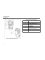
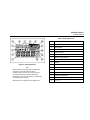
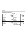
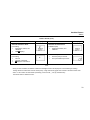
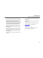
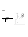
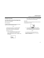
GasAlert Extreme
O2, CO, H2S, PH3, SO2, Cl2, NH3, NO2, HCN, ETO, ClO2, O3, or NO
Single Gas Detector
User Manual
D5561/4 English
iERP: 117000
© 2005 BW Technologies. All rights reserved. Printed in Canada.
All product names are trademarks of their respective companies.
Limited Warranty & Limitation of Liability
BW Technologies LP (BW) warrants this product to be free from defects in material and workmanship under normal use and service for a period of two years, beginning on
the date of shipment to the buyer. This warranty extends only to the sale of new and unused products to the original buyer. BW’s warranty obligation is limited, at BW’s
option, to refund of the purchase price, repair, or replacement of a defective product that is returned to a BW authorized service center within the warranty period. In no event
shall BW’s liability hereunder exceed the purchase price actually paid by the buyer for the Product.
This warranty does not include:
a)
fuses, disposable batteries or the routine replacement of parts due to the normal wear and tear of the product arising from use;
b)
any product which in BW’s opinion, has been misused, altered, neglected or damaged by accident or abnormal conditions of operation, handling or use;
c)
any damage or defects attributable to repair of the product by any person other than an authorized dealer, or the installation of unapproved parts on the
product; or
The obligations set forth in this warranty are conditional on:
a)
proper storage, installation, calibration, use, maintenance and compliance with the product manual instructions and any other applicable recommendations
of BW;
b)
the buyer promptly notifying BW of any defect and, if required, promptly making the product available for correction. No goods shall be returned to BW
until receipt by the buyer of shipping instructions from BW; and
c)
the right of BW to require that the buyer provide proof of purchase such as the original invoice, bill of sale or packing slip to establish that the product is
within the warranty period.
THE BUYER AGREES THAT THIS WARRANTY IS THE BUYER’S SOLE AND EXCLUSIVE REMEDY AND IS IN LIEU OF ALL OTHER WARRANTIES, EXPRESS OR
IMPLIED, INCLUDING BUT NOT LIMITED TO ANY IMPLIED WARRANTY OF MERCHANTABILITY OR FITNESS FOR A PARTICULAR PURPOSE. BW SHALL NOT BE
LIABLE FOR ANY SPECIAL, INDIRECT, INCIDENTAL OR CONSEQUENTIAL DAMAGES OR LOSSES, INCLUDING LOSS OF DATA, WHETHER ARISING FROM
BREACH OF WARRANTY OR BASED ON CONTRACT, TORT OR RELIANCE OR ANY OTHER THEORY.
Since some countries or states do not allow limitation of the term of an implied warranty, or exclusion or limitation of incidental or consequential damages, the limitations and
exclusions of this warranty may not apply to every buyer. If any provision of this warranty is held invalid or unenforceable by a court of competent jurisdiction, such holding will
not affect the validity or enforceability of any other provision.
BW Technologies LP
2840 – 2nd Ave. SE
Calgary, AB T2A 7X9
Canada
BW Technologies Inc. (America)
3279 West Pioneer Parkway
Arlington, TX 76013
USA
BW Europe Ltd.
101 Heyford Park,
Upper Heyford, Oxfordshire OX25 5HA
United Kingdom
Table of Contents
Title
Page
Introduction ..................................................................................................................................... 1
Contacting BW Technologies ........................................................................................................ 2
Safety Information - Read First...................................................................................................... 2
Getting Started................................................................................................................................. 5
Activating the Detector................................................................................................................... 9
Self-Test................................................................................................................................. 9
Self-Test Pass ..................................................................................................................... 13
Self-Test Fail........................................................................................................................ 13
Deactivating the Detector.............................................................................................................. 14
Confidence Beep............................................................................................................................ 14
User Options Menu ........................................................................................................................ 15
Exit Option ........................................................................................................................... 16
Clock Option ........................................................................................................................ 17
Pass Code Protection Option .............................................................................................. 18
Stealth Mode Option ............................................................................................................ 21
Automatic Backlight Option ................................................................................................. 22
Latching Alarm Option ......................................................................................................... 23
Automatic Oxygen (O2) Calibration Option.......................................................................... 23
Calibration Past Due Option ................................................................................................ 24
i
GasAlert Extreme
User Manual
Languages ...........................................................................................................................25
Datalogger Sampling Rate Option .......................................................................................28
Data Transfer Option ...........................................................................................................29
Datalog and Event Log...................................................................................................................31
Datalog.................................................................................................................................31
Event Log .............................................................................................................................31
Alarms .............................................................................................................................................32
Computed Gas Exposures...................................................................................................34
Viewing Gas Exposures.......................................................................................................34
Gas Alarm Setpoints ............................................................................................................35
Resetting Gas Alarm Setpoints............................................................................................36
Stopping a Gas Alarm..........................................................................................................37
Sensor Alarm .......................................................................................................................37
Low Battery Alarm................................................................................................................37
Automatic Shutdown Alarm .................................................................................................38
Calibration and Setting Alarm Setpoints......................................................................................38
Guidelines ............................................................................................................................38
Test Cap ..............................................................................................................................40
Calibration Procedure ..........................................................................................................41
Maintenance ....................................................................................................................................48
Cleaning a Sensor Screen...................................................................................................48
Cleaning a Sensor ...............................................................................................................48
Clearing a Sensor ................................................................................................................48
Replacing the Battery or Sensor...................................................................................................49
Troubleshooting .............................................................................................................................51
Replacement Parts and Accessories............................................................................................54
Specifications..................................................................................................................................55
General Specifications for Datalogger Units ...............................................................................56
ii
List of Tables
Table
Title
Page
1.
2.
3.
4.
5.
6.
7.
8.
9.
10.
11.
12.
13.
GasAlert Extreme Models .....................................................................................1
International Symbols............................................................................................4
GasAlert Extreme Detector ...................................................................................6
Display Elements ..................................................................................................7
Pushbuttons ..........................................................................................................8
Alarms.................................................................................................................32
Computed Gas Exposures ..................................................................................34
Gas Alarm Setpoints ...........................................................................................35
Factory Alarm Setpoints ......................................................................................36
Test Cap .............................................................................................................40
Replacing the Battery or Sensor .........................................................................50
Troubleshooting Tips...........................................................................................51
Replacement Parts and Accessories ..................................................................54
iii
GasAlert Extreme
User Manual
iv
List of Figures
Figure
Title
Page
1.
2.
3.
4.
GasAlert Extreme Detector ............................................................................................ 6
Display Elements ........................................................................................................... 7
Test Cap....................................................................................................................... 40
Replacing the Battery or Sensor .................................................................................. 50
i
GasAlert Extreme
User Manual
vi
GasAlert Extreme
Model
Introduction
aWarning
To ensure your personal safety, read “Safety
Information” before using the detector.
The GasAlert Extreme gas detector (“the detector”) warns of
hazardous gas at levels above a factory set alarm setpoint.
This product is a gas detector, not a measurement device.
Gas Monitored
GasAlert Extreme H2S
Hydrogen sulfide (ppm)
GasAlert Extreme H2S
Hydrogen sulfide (ppm)
Low methanole
GasAlert Extreme PH3
Phosphine (ppm)
GasAlert Extreme SO2
Sulfur dioxide (ppm)
The detector is a personal safety device.It is your
responsibility to respond properly to the alarms.
GasAlert Extreme Cl2
Chlorine (ppm)
GasAlert Extreme NH3
Ammonia (ppm)
Table 1 lists the GasAlert Extreme models. This manual
includes examples from each model.
GasAlert Extreme NH3
Ammonia (ppm)
Table 1. GasAlert Extreme Models
Model
Gas Monitored
GasAlert Extreme O2
Oxygen (% by volume)
GasAlert Extreme CO
Carbon monoxide (ppm)
GasAlert Extreme CO
Carbon monoxide (ppm)
GasAlert Extreme H2S
Hydrogen sulfide (ppm)
Low H2 sensitivity
High range
GasAlert Extreme NO2
Nitrogen dioxide (ppm)
GasAlert Extreme HCN
Hydrogen cyanide (ppm)
GasAlert Extreme ETO
Ethylene oxide (ppm)
GasAlert Extreme ClO2
Chlorine dioxide (ppm)
GasAlert Extreme O3
Ozone (ppm)
GasAlert Extreme NO
Nitric oxide (ppm)
High range
1
GasAlert Extreme
User Manual
Contacting BW Technologies
Safety Information - Read First
To contact BW Technologies, call:
Use the detector only as specified in this manual, otherwise
the protection provided by the detector may be impaired.
USA: 1-888-749-8878
Canada: 1-800-663-4164
Europe: +44 (0) 1869 233004
Other countries: +1-403-248-9226
Address correspondence to:
BW Technologies LP
2840 – 2 Avenue S.E.
Calgary, AB T2A 7X9
CANADA
Email us at: [email protected]
Visit BW Technologies’ web site at: www.gasmonitors.com
ISO 9001
2
International symbols used on the detector and in this manual
are explained in Table 2.
Read the Warnings and Cautions on the following pages
before using the detector.
c Note
This instrument contains a lithium battery. Do
not mix with the solid waste stream. Spent
batteries should be disposed of by a qualified
recycler or hazardous materials handler.
GasAlert Extreme
Safety Information - Read First
a Caution
To avoid possible personal injury:
⇒
Warning: Substitution of components may impair Intrinsic Safety.
⇒
Warning: To prevent ignition of flammable or combustible atmospheres, disconnect power before servicing.
⇒
Do not use the detector if it is damaged. Before using the detector, inspect the case. Look for cracks or missing
plastic.
⇒
If the detector is damaged or parts are missing, contact BW Technologies immediately.
⇒
Make sure the back is closed and fastened before operating the detector.
⇒
Use only a sensor specifically designed for your GasAlert Extreme model. Refer to Replacement Parts and
Accessories.
⇒
Make sure the sensor screen is not blocked.
⇒
Periodically test the sensor’s response to gas by exposing the detector to a targeted gas concentration that
exceeds the high alarm setpoint. Manually verify that the audible and visual alarms are activated.
⇒
Calibrate the detector before first-time use, and then at least once every 180 days. (For HCN detectors, calibrate
once every 90 days.)
⇒
Do not turn off the detector during a work shift. Turning off the detector resets the TWA (time-weighted average),
STEL (short-term exposure limit), and maximum gas exposure values to 0. Refer to Alarms.
⇒
Use only the following battery: Energizer 1CR2. Refer to Replacing the Battery or Sensor.
⇒
To reduce the risk of ignition of a flammable atmosphere, batteries must only be changed in an area known to be
nonflammable.
3
GasAlert Extreme
User Manual
a Caution
To avoid possible damage to the detector:
⇒
Do not expose the detector to electrical shock and/or severe continuous mechanical shock.
⇒
Do not attempt to disassemble, adjust, or service the detector unless instructions for that procedure are contained
in the user manual and/or that part is listed as a replacement part. Use only BW Technologies Replacement Parts.
⇒
The detector warranty will be voided if customer personnel or third parties damage the detector during repair
attempts. Non-BW Technologies repair/service attempts void this warranty.
⇒
The oxygen GasAlert Extreme detector is classified by Underwriters Laboratories Inc. up to an atmosphere of 21%
oxygen.
Table 2. International Symbols
Symbol
h
4
Meaning
Classified to both U.S. and Canadian Safety standards by Underwriter’s Laboratories, Inc.
X
Conforms to European Union Directives
g
European Explosives Protection
ATEX
Conforms to European ATEX Directives
IECEx
International Electrotechnical Commission Scheme for Certification to Standards for Electrical Equipment for
Explosive Atmospheres
GasAlert Extreme
Getting Started
Getting Started
The items listed below are included with the detector. If the
detector is damaged or parts are missing, contact the place of
purchase immediately.
•
3 V lithium CR2-series battery.
•
GasAlert Extreme O2 model: O2 sensor;
GasAlert Extreme CO model: CO sensor
(low H2 sensitivity);
GasAlert Extreme CO model: CO sensor;
GasAlert Extreme H2S model: H2S sensor (high range);
GasAlert Extreme H2S model: H2S sensor (low methanol);
GasAlert Extreme H2S model: H2S sensor;
GasAlert Extreme PH3 model: PH3 sensor;
GasAlert Extreme SO2 model: SO2 sensor;
GasAlert Extreme Cl2 model: Cl2 sensor;
GasAlert Extreme NH3 model: NH3 sensor;
GasAlert Extreme NH3 model: NH3 sensor (high range);
GasAlert Extreme NO2 model: NO2 sensor;
GasAlert Extreme HCN model: HCN sensor;
GasAlert Extreme ETO model: ETO sensor;
GasAlert Extreme ClO2 model: ClO2 sensor;
GasAlert Extreme O3 model: O3 sensor;
GasAlert Extreme NO model: NO sensor.
•
The detector is shipped with the battery and sensor installed.
To order replacement parts and accessories, refer to
Replacement Parts and Accessories.
To become familiar with the features and functions of the
detector, study the following figures and tables:
•
Figure 1 and Table 3: GasAlert Extreme Detector
(describes the detector’s components).
•
Figure 2 and Table 4: Display Elements
(describes the LCD screen and icons).
•
Table 5: Pushbuttons
(describes the buttons on the detector).
Test cap and hose.
5
GasAlert Extreme
User Manual
Table 3. GasAlert Extreme Detector
Item
Figure 1. GasAlert Extreme Detector
6
Description
1
Visual alarm
2
Liquid crystal display (LCD)
3
Pushbuttons
4
Audible alarm
5
Sensor and sensor screen
6
Infrared communication port
7
Alligator clip
GasAlert Extreme
Getting Started
Table 4. Display Elements
Item
Description
1
Numeric value
2
Gas cylinder
3
Automatically span sensor
4
Pass code lock
5
Set alarm setpoints and user options
6
Maximum gas exposure
7
Alarm conditions
8
Battery
Figure 2. Display Elements
9
Data transmission
Note
10
Alarm or alarm setpoint
When enabled, the backlight option automatically
activates for 3 seconds whenever there is
insufficient light to view the LCD. Press and hold
(until light activates) any button to activate the
backlight for 6 seconds. The detector is shipped with
the backlight option enabled.
11
Automatically zero sensor
12
Optional datalogger indicator
13
Parts per million (ppm)
14
Percentage by volume (% vol.)
Backlight does not operate while in stealth mode.
15
Percentage by lower explosive limit (% LEL)
(future use)
7
GasAlert Extreme
User Manual
Table 5. Pushbuttons
Pushbutton
A
Description
•
To activate the detector, press A.
•
To enable/disable the confidence beep, while the detector is deactivated press and hold C. While
holding C, press A. This enables/disables the confidence beep while activating start-up.
•
To deactivate the detector, press A and hold until OFF displays (approximately 5 seconds). If the
detector is pass code protected to prevent deactivation, PASS will display. A pass code must be
entered to deactivate the detector. For more information refer to No Deactivation Pass Code
Protection.
•
To decrement the displayed value or to scroll down, press E.
•
To enter the user options menu, press E and D simultaneously and hold until OPIN and then EXIT
displays (approximately 5 seconds) .
•
To initiate calibration and setting alarm setpoints, press and hold E and C simultaneously until CAL.
displays.
•
To increment the displayed value, press D.
•
To view the TWA, STEL and maximum (MAX) gas exposures, press D and C simultaneously.
•
To save a displayed value, press C.
•
To clear TWA, STEL, and maximum (MAX) gas exposures, press and hold C for 6 seconds.
•
To acknowledge a latched alarm, press C.
E
D
C
8
GasAlert Extreme
Activating the Detector
detector performs an automatic shutdown. Refer to
Automatic Shutdown Alarm.
Activating the Detector
To activate the detector, press A.
The detector begins a self-test.
Date and Time: The LCD displays the date and
time automatically in the following order.
Year: The LCD displays the
current year (20XX).
Self-Test
When the detector is activated it performs several system
tests. Verify that all tests have been performed prior to using
the detector.
1.
4.
Display Elements Test: The LCD displays all of
the screen elements.
Month:
JAN, FEB, MAR, etc.
Day of the month: (1 to 31)
2.
Alarm Function Test: The audible alarm beeps,
the visual alarm flashes, the backlight activates
briefly, and the detector emits one vibration.
Note
Day of the week:
MON, TUE, WED, etc.
Hour/Minute:
00:00 hours to 23:59 hours
The following tests are listed in the order they are
automatically performed on the detector.
3.
Battery Test: The detector tests the batteries. If
the battery voltage is too low to continue, the
To adjust the date or time, refer to Clock (CLCK)
option.
9
GasAlert Extreme
User Manual
5.
Sensor Test: The detector now tests the sensor. If
the sensor test fails, the audible alarm emits a
slow tone, the visual alarm flashes slowly, and the
ALARM flashes.
If the battery is low, the LCD displays the low
battery icon and the self-test continues.
TWA Alarm Setpoint: The LCD displays the TWA
alarm setpoint.
If the sensor test passes, the self-test continues.
6.
Gas Type: The LCD displays the type of gas the
detector is manufactured to measure.
Note
The TWA alarm setpoint screen does not apply to
O2 detectors.
Refer to Table 1: GasAlert Extreme Models.
10
GasAlert Extreme
Activating the Detector
7.
STEL Alarm Setpoint: The LCD displays the
STEL alarm setpoint.
Note
The TWA alarm setpoint screen does not apply to
O2 detectors.
8.
9.
High Alarm Setpoint: The LCD displays the high
alarm setpoint.
10. Calibration Due Test: The LCD displays the
calibration due date.
Low Alarm Setpoint: The LCD displays the low
alarm setpoint.
The LCD displays the number of days remaining
before the detector must be calibrated. For more
information, refer to Calibration Procedures.
11
GasAlert Extreme
User Manual
If calibration is past due, a warning message
displays.
Press D or E to scroll to the required pass code, and
within 10 seconds press C to confirm the selection. The
LCD then displays the normal operating screen.
Press C to acknowledge the warning message.
Note
Depending upon if the detector is pass code
protected or not, one of the following three events
will occur.
1) Not Pass Code Protected: If the detector is not pass
code protected, after the CAL. PAST message is
acknowledged, the detector continues the self-test and then
enters normal operating mode.
2) Pass Code Protected: If the detector is pass code
protected, when CAL. PAST displays, press C to
acknowledge the message and to access the PASS screen.
If required, refer to Pass Code Protection Option.
12
Calibrate the detector before continuing operation.
If the pass code is not confirmed within 10 seconds or the
pass code is incorrect, the LCD displays the following
screen.
The detector then automatically deactivates.
GasAlert Extreme
Activating the Detector
3) Automatic Shutdown: If the pass code is not known the
detector beeps and flashes eight times while the LCD
displays the following screen.
For information regarding bump check tests, refer to the
MicroDock ll User Manual.
Self-Test Pass
If the detector passes the self-test, it enters normal
operating mode. The LCD displays the ambient gas reading.
The detector then automatically deactivates.
Bump Check Fail Test: If a bump check has not been
performed or if the bump check was performed but failed,
the detector beeps, flashes, vibrates, and the following error
message displays:
Press C to acknowledge the alarm.
Note
The detector begins recording immediately. It records the
•
maximum (MAX) gas exposure,
•
the short-term exposure levels (STEL), and
•
calculates the time-weighted average (TWA).
Self-Test Fail
If the detector fails the self-test, refer to Troubleshooting.
Bump check the detector before continuing
operation.
13
GasAlert Extreme
User Manual
Deactivating the Detector
Note
A detector can be enabled to not deactivate by
enabling a second pass code protection option. If
PASS displays immediately after OFF, refer to No
Deactivation Pass Code Protection.
To deactivate the detector, complete the following:
Confidence Beep
The confidence beep is used to confirm that the detector is
activated and the batteries have sufficient power to respond
to a hazardous level of gas.
When battery power is sufficient, the audible alarm beeps
once every 5 seconds. The confidence beep stops when
battery power is low. The confidence beep can be enabled
or disabled.
Press and hold A until OFF displays (approximately 5
seconds).
Note
The detector is shipped with the confidence beep
disabled.
To enable/disable the confidence beep, complete the
following:
The audible alarm beeps four times, the visual alarm flashes
four times, the detector vibrates, and then powers off.
1.
Ensure the detector is deactivated.
2.
Press and hold C. While holding C, press A.
Note
If A is not held down until OFF displays, the
detector will remain activated.
14
When the confidence beep option is enabled, the
detector automatically begins beeping when
activated.
GasAlert Extreme
User Options Menu
When the confidence beep option is enabled in
stealth mode, the detector vibrates once every 60
seconds. For more information refer to Stealth
Option and Alarms.
If the detector is pass code protected, the following
screen displays:
User Options Menu
The user options menu provides access to fourteen user
selections.
2.
To access the user options menu, complete the following:
1.
From the normal operating screen, press and hold
D and E simultaneously until OPTN displays
and then release the buttons.
Press D or E to scroll to the required pass code.
Press C to confirm the selection and access the
EXIT screen.
Note
If the pass code is not confirmed within 10
seconds, the following error message displays.
The detector beeps four times, flashes four times,
and vibrates while accessing the user options
menu.
If the pass code protection is not enabled, the
EXIT screen automatically displays.
3.
From the EXIT screen, press D or E to scroll
through all of the user options.
15
GasAlert Extreme
User Manual
4.
Press C to select a displayed option.
Note
As a safety precaution, if an option is not selected
within 20 seconds the detector automatically
returns to normal operating mode.
When the required activities have been performed
for a selected option, the EXIT screen
automatically displays.
5.
16
Press D or E to select another option or press
C to exit the user options menu and return to
normal operating mode.
Exit Option
When user options is entered, the EXIT screen displays
immediately following the options (OPTN) screen. The LCD
automatically returns to the EXIT screen after a user option
function has been completed.
From the EXIT screen, use D or E to scroll to additional
user options,
or
Press C to exit user options and return to normal operating
mode.
GasAlert Extreme
User Options Menu
Clock Option
The clock (CLCK) option is used to set the date
(year/month/day/day of the week) and time (hour/minute) of
the detector. To set the time or date complete the following:
1.
From the EXIT screen, press D or E to scroll to
the CLCK option.
2.
Press C to select the option and access the first
date/time option, the year screen. Set and the
value(s) that is currently available to change
continually flash.
3.
Press D or E to scroll to the required year (last
two numerals only) and press C to confirm the
selection.
Or
To bypass the year, press C to retain the current
value and automatically proceed to the month
screen.
Note
The time and date values can only be changed in
the order they are presented in this table. To
bypass any setting, press C. The detector
automatically retains the current value and
proceeds to the next date/time option.
Year: Requires only the last two
numerals of the year (00-99).
Month: Scroll to select the required
month
(JAN, FEB, MAR, etc.).
Day: Scroll to select the required
day (1-31). For months that have
30 days only (1-30) will be
available to select from. For Feb
the options are (1-28 and 29).
4.
Repeat step #3 for the remaining date/time
changes.
Day of the week: Scroll to select
the required day
(Mon, Tue, Wed, etc.).
5.
Press D or E to select another option or press
C to exit the user options menu and return to
normal operating mode.
Time: The hour value flashes first.
Scroll to select
(0:00 hrs. to 23:59 hrs.).
17
GasAlert Extreme
User Manual
Note
If an option is not selected or bypassed
(confirmed) by pressing C within 10 seconds, the
LCD automatically times-out and returns to the
EXIT screen.
If a value is selected but not confirmed, an error
message displays and then proceeds to the next
date/time option.
Pass Code Protection Option
The pass code protection option (PASS) is used to prevent
access to the user options and the calibration/set alarm
setpoint functions.
The pass code protection option can be enabled or
disabled.
Note
The detector is shipped with the pass code
protection option disabled.
18
Enable Pass Code Protection
To enable pass code protection, complete the following:
Note
The pass code is provided on a separate card
inside the shipping container.
1.
From the EXIT screen in user options, press
D or E to select the PASS option.
2.
Press C to confirm the selection.
3.
Set PASS begins flashing. Press D or E to
select the pass code number, and press C to
confirm the selection.
4.
The flashing pass ON screen displays. Press C to
confirm. The LCD then returns to the user options
EXIT screen.
GasAlert Extreme
User Options Menu
5.
Press D or E to select another user option, or
press C to exit the user options and return to
normal operating mode.
Note
2.
If an incorrect pass code is selected or a correct
pass code is not confirmed within 10 seconds, the
following error message displays and the LCD
returns to the EXIT screen.
Press D or E to select the pass code and press
C to confirm. The following EXIT screen displays.
The key icon indicates that the pass code
protection is currently enabled.
Disable Pass Code Protection
When the detector is pass code protected, the key icon
displays continually. To disable the pass code protection
option, complete the following:
1.
Press and hold D and E simultaneously to
access the user options menu.
The OPTN screen displays briefly before the
flashing pass code screen displays.
3.
Press D or E to scroll to the PASS option, and
press C to confirm the selection.
4.
The LCD displays a flashing OFF screen. Press C
to confirm the disabling option.
Note
To ensure if the pass code protection option is
enabled/disabled, use D and E to toggle
between the ON and OFF options. Display the
desired option and press C to confirm the
selection.
19
GasAlert Extreme
User Manual
The LCD returns to the user options EXIT screen.
5.
Press D or E to select another user option, or
press C to exit the user options and return to
normal operating mode.
To deactivate the detector, complete the following:
1.
From normal operating mode, press and hold A
to deactivate the detector.
If the detector is pass code protected to prevent
powering down, OFF displays briefly and then
PASS immediately displays.
No Deactivation Pass Code Protection
Note
A detector can be enabled to prevent deactivation
without a pass code. If requested, the detector is
shipped with this option enabled permanently. This
option cannot be disabled by a customer.
2.
As a backup safety precaution, the detector can be
manufactured to prevent deactivation. A separate security
pass code is required to for this option and will be available
to limited personnel only.
The pass code must be entered every time the detector is
deactivated.
20
Press D or E to select the security pass code.
Press C to confirm the selection.
The detector then deactivates.
GasAlert Extreme
User Options Menu
Stealth Mode Option
2.
The stealth (STLH) mode option is designed to ensure that
the detector is undetected in situations that require
concealment. This option is used to disable the
•
audible alarms,
•
visual alarms, and
•
backlight.
Enabled
3.
Only the vibrate alarm remains enabled.
The detector is shipped with stealth mode
disabled.
To enable/disable the stealth mode, complete the following:
From the EXIT screen of the user options menu,
press D or E to select the STLH option.
Disabled
Press D or E to toggle between the ON/OFF
options. Ensure the desired option is displayed
and press C to confirm the selection.
The LCD returns to the EXIT screen.
Note
1.
Press C to confirm the selection. The LCD flashes
eitherON or OFF.
If stealth mode has been enabled, the screen displays
STLH continually unless
•
functions are being performed,
•
readings are not 0 ppm for toxics, or
•
reading is not 20.9% vol for oxygen.
Note
The vibrator alarm is disabled at -20°C.
21
GasAlert Extreme
User Manual
4.
Press D or E to scroll to a new user option or
press C to exit and return to normal operating
mode.
Automatic Backlight Option
2.
The automatic backlight (BKLT) option is used to enable or
disable the automatic backlight of the detector. When
enabled, the backlight automatically turns on for 3 seconds
whenever there is insufficient light to view the LCD.
Press C to accept the option. The LCD flashes
either ON or OFF.
3.
Press D or E to toggle between the ON/OFF
options. Ensure the desired option is displayed
and press C to confirm the selection.
Press and hold (until backlight activates) any button to
activate the backlight for 6 seconds.
The LCD returns to the EXIT screen.
Note
Note
The detector is shipped with the automatic
backlight option enabled. Backlight does not
operate while in stealth mode.
To enable/disable the automatic backlight, complete the
following:
1.
22
From the EXIT screen of the user options menu,
use D or E to scroll to the BKLT option.
The BKLT option is not available in the user
options menu while stealth mode is enabled.
4.
Press D or E to scroll to a new user option or
press C to exit and return to normal operating
mode.
GasAlert Extreme
User Options Menu
Latching Alarm Option
2.
The latch alarm (LTCH) alarm option is used to ensure that
an alarm persists until it is acknowledged by the user.
Press C to accept the option. The LCD flashes
eitherON or OFF.
3.
Press D or E to toggle between the ON/OFF
options. Ensure the desired option is displayed
and press C to confirm the selection.
In the event of an alarm condition, and if the high and low
alarms are set to latch, the audible and visual alarms persist
until the alarm is acknowledged.
In stealth mode, the detector continues to vibrate until the
alarm is acknowledged.
The LCD returns to the EXIT screen.
4.
Press D or E to scroll to a new user option or
press C to exit and return to normal operating
mode.
Note
The detector is shipped with the latching alarm
option disabled.
To enable/disable the latching alarm option, complete the
following:
1.
From the EXIT screen of the user options menu,
press D or E to scroll to the LTCH option.
Automatic Oxygen (O2) Calibration Option
Note
For oxygen detectors only.
This option is used to enable/disable the automatic oxygen
(O2) calibration. The O2 calibration begins automatically
during start-up after the calibration due screen displays.
Note
The detector is shipped with the automatic O2
calibration option disabled.
23
GasAlert Extreme
User Manual
To enable/disable the automatic O2 calibration option,
complete the following:
1.
From the EXIT screen of the user options menu,
press D or E to scroll to the ACAL option.
Calibration Past Due Option
The calibration past due (PAST) option is used to enable an
automatic shutdown during start-up if the detector is past
due for calibration.
Note
The detector is shipped with the calibration past
due shutdown option disabled.
2.
Press C to accept this option and display the
current mode ON or OFF.
3.
Press D or E to toggle between the ON/OFF
options. Ensure the desired option is displayed
and press C to confirm the selection.
To enable/disable the calibration past due automatic
shutdown option, complete the following:
1.
From the EXIT screen of the user options menu,
press D or E to scroll to the PAST option.
2.
Press C to accept the option and to display the
current mode (ON or OFF).
The LCD returns to the EXIT screen.
4.
24
Press D or E to scroll to a new user option or
press C to exit and return to normal operating
mode.
GasAlert Extreme
User Options Menu
3.
Press D or E to toggle between the ON/OFF
options. Ensure the desired option is displayed
and press C to confirm the selection.
1.
From the EXIT screen of the user options menu,
press D or E to scroll to the PORT option.
2.
Press C to accept the option. The LCD then
displays the EXIT screen in Portuguese.
3.
Press D or E to scroll to a new user option or
press C to exit and return to normal operating
mode.
The LCD returns to the EXIT screen.
4.
Press D or E to scroll to a new user option or
press C to exit and return to normal operating
mode.
Languages
The detector can be set to display text in different
languages. Refer to the following language options:
Portuguese Option
The Portuguese (PORT) option is used to convert all of the
LCD screens to display the text in Portuguese.
Note
If the language option is included, the detector is
shipped with English selected as the default.
25
GasAlert Extreme
User Manual
Spanish Option
German Option
The Spanish (ESPA) option is used to convert all of the LCD
screens to display the text in Spanish.
The German (DEUT) option is used to convert all of the LCD
screens to display the text in German.
Note
Note
If the multi-language option is included, the
detector is shipped with English selected as the
default.
26
1.
From the EXIT screen of the user options menu,
press D or E to scroll to the ESPA option.
2.
Press C to accept the option. The LCD then
displays the EXIT screen in Spanish.
3.
Press D or E to scroll to a new user option or
press C to exit and return to normal operating
mode.
If the language option is included, the detector is
shipped with English selected as the default.
1.
From the EXIT screen of the user options menu,
press D or E to scroll to the DEUT option.
2.
Press C to accept the option. The LCD then
displays the EXIT screen in German.
3.
Press D or E to scroll to a new user option or
press C to exit and return to normal operating
mode.
GasAlert Extreme
User Options Menu
French Option
English Option
The French (FRAN) option is used to convert all of the LCD
screens to display the text in French.
The English (ENGL) option is used to convert all of the LCD
screens to display the text in English.
Note
Note
If the language option is included, the detector is
shipped with English selected as the default.
If the language option is included, the detector is
shipped with English selected as the default.
1.
From the EXIT screen of the user options menu,
press D or E to scroll to the FRAN option.
1.
From the EXIT screen of the user options menu,
press D or E to scroll to the ENGL option.
2.
Press C to accept the option. The LCD then
displays the EXIT screen in French.
2.
Press C to accept the option. The LCD then
displays the EXIT screen in English.
3.
Press D or E to scroll to a new user option or
press C to exit and return to normal operating
mode.
3.
Press D or E to scroll to a new user option or
press C to exit and return to normal operating
mode.
27
GasAlert Extreme
User Manual
Datalogger Sampling Rate Option
2.
Press C to select the option and display the
sample rate screen.
3.
The sample rate screen displays the current
selected rate. Press D or E to scroll to a new
rate and press C to save the new value.
4.
Press D or E to scroll to a new user option or
press C to exit and return to normal operating
mode.
The datalogger sampling rate (RATE) option is used
determine how often the detector is to record a sample. The
datalogger value ranges from 1 to 60 seconds.
Note
The detector is shipped with the factory default set
to sample every 5 seconds.
To adjust the datalogger sampling rate, complete the
following:
1.
28
From the EXIT screen of the user options menu,
press D and E to scroll to the RATE option.
GasAlert Extreme
User Options Menu
Data Transfer Option
3.
The data transfer (SEND) option is used to transfer the
datalog/event log information from the detector to the PC.
Press C to accept the option and to access the
data transfer option screens.
4.
Select one of the following options to transfer data.
Note
An IR DataLink (or other BW accessory) is
required to transfer the data from the detector to
the PC.
To transfer data, complete the following:
1.
Connect the IR DataLink (or other BW accessory)
to the detector and the PC.
Press D or E to scroll to the event
(EVNT) option. Press C to
automatically transfer all of the
events.
Press D or E to scroll to the last
(LAST) option. Press C to
automatically send all of the datalogs
since the last time they were
downloaded.
Refer to the IR DataLink Instruction Sheet.
2.
From the EXIT screen of the user options menu,
press D or E to scroll to the SEND option.
Press D or E to scroll to the all
(ALL) option. Press C to
automatically send all of the
datalogs that are saved on the
detector.
When the transfer(s) is complete, the LCD automatically
returns to the EXIT screen.
29
GasAlert Extreme
User Manual
LAST and ALL Transfers
Unsuccessful Transfer
If the LAST or ALL option is selected, the LCD displays a
countdown and the data transmission icon to notify that the
data is transferring.
If the connection between the detector and the IR DataLink
is disturbed during a transfer, the following error message
displays.
Note
The number that the countdown begins at is
dependant upon the amount of data that is being
transferred.
The LCD then returns to the EXIT screen.
1.
From the PC, save the previously transferred data
to ensure that it will not be deleted.
2.
Repeat steps #3-5 (back to the beginning of the
Data Transfer Option section).
3.
From the detector, select LAST to automatically
resume the transfer from where it stopped
sending.
EVNT Transfer
When event logs are transferred, nothing displays on the
LCD as there is little data to transfer.
Or
Select ALL to transfer all of the data again.
30
GasAlert Extreme
Datalog and Event Log
Datalog and Event Log
The GasAlert Extreme datalogger version allows the
detector to record various information so a report can be
compiled.
Datalog
Datalog information is recorded based upon the sampling
rate set in the detector user options. The following
information is recorded in a datalog:
•
The date and time;
•
The detector serial number;
•
The type of gas the detector monitors;
•
The current gas reading;
•
The sensor status;
•
•
Confidence beep is on/off;
•
Automatic backlight is on/off;
•
Stealth mode is on/off;
•
Latching alarm is on/off;
•
The calibration past due user option is on/off; and
•
The language that the LCD displays.
Event Log
An event log is data that is recorded when an event (i.e., an
alarm) occurs. The following information is recorded in an
event log:
•
The detector serial number;
•
The type of exposure the detector experienced;
The detector status;
•
The time the alarm started and ended; and
•
Pass code protect is on/off;
•
The peak exposure of the alarm.
•
The period that STEL is calculated;
31
GasAlert Extreme
User Manual
Table 7 describes the computed gas exposures.
Alarms
Table 6 describes detector alarms and shows how the LCD
looks for each alarm.
Table 6. Alarms
Alarm
Display
Alarm
Low Alarm:
TWA Alarm:
•
•
•
•
•
•
•
•
Slow tone
Slow flash
ALARM flashes
Slow vibrations
Slow tone
Slow flash
ALARM flashes
Slow vibrations
High Alarm:
STEL Alarm:
•
•
•
•
•
•
•
•
Fast tone
Fast flash
ALARM flashes
Fast vibrations
Fast tone
Fast flash
ALARM flashes
Fast vibrations
Sensor Alarm:
Low Battery Alarm:
•
•
•
•
• One beep and one flash every 5
seconds, and one quick vibration
every minute (when confidence
beep is disabled).
• No beeps, flashes, or vibrations
(when confidence beep is enabled)
• LOW displays
32
Slow tone
Slow flash
ALARM flashes
Slow vibrations
Display
GasAlert Extreme
Alarms
Table 6. Alarms (cont.)
Alarm
Display
Alarm
Automatic Shutdown Alarm:
(Low battery)
•
•
Automatic Shutdown Alarm:
(Calibration past)
•
Eight beeps, flashes, and
vibrations
LOW displays
After Automatic Shutdown:
(Low battery)
•
•
•
Display
Eight beeps, flashes, and
vibrations
Confidence Beep:
•
•
No tone
No flash or vibrations
displays for a short time
One beep every 5 seconds
One quick vibration per minute
Note
During an alarm condition, the detector activates the backlight and the LCD displays the current ambient gas reading.
The high alarm and STEL alarm have the same priority. A high alarm and/or STEL alarm override a low alarm and/or TWA
alarm. To check STEL and TWA alarms specifically, press and hold C and D simultaneously.
The vibrator alarm is disabled at -20°C.
33
GasAlert Extreme
User Manual
Viewing Gas Exposures
Computed Gas Exposures
aWarning
To avoid possible personal injury, do not
deactivate the detector during a work shift. The
detector automatically resets the TWA, STEL,
and MAX gas exposures at start-up. If the
detector is restarted during a work shift, the
values will not reflect the entire work shift.
Table 7. Computed Gas Exposures
Gas Exposure
TWA
•
•
•
MAX*
•
Time-weighted average based
on an 8-hour workday.
Accumulated value.
The LCD next displays the STEL gas exposure.
Lastly, the LCD displays the MAX gas exposure.
Short-term exposure limit based
on a 15-minute period.
Accumulated value.
Highest gas level encountered
during the period the detector is
turned on.
*Maximum gas exposure for oxygen describes the furthest
level reached from 20.9% vol.
34
Press C and D simultaneously. The LCD displays the TWA
gas exposure first.
Description
•
STEL
Toxic Gases
Press C and hold for 6 seconds to clear the TWA, STEL,
and MAX gas exposure. The detector emits two beeps and
two vibrations to confirm that the exposures have been
cleared.
GasAlert Extreme
Alarms
Oxygen
For oxygen detectors, press C and D simultaneously to
view both the maximum low and maximum high levels of
oxygen exposure.
Gas Alarm Setpoints
Table 8. Gas Alarm Setpoints
Alarm
Condition
TWA alarm
TWA above TWA alarm setpoint.
(O2: not applicable)
STEL alarm
STEL above STEL alarm setpoint.
(O2: not applicable)
Low alarm
Toxic gases: Ambient gas level
above low alarm setpoint.
The detector gas alarm setpoints trigger the gas alarms that
are described in Table 8.
O2: ambient gas level may be set
to above or below 20.9%.
High alarm
Toxic gases: ambient gas level
above high alarm setpoint.
O2: ambient gas level may be set
to above or below 20.9%.
35
GasAlert Extreme
User Manual
Resetting Gas Alarm Setpoints
Gas
Note
TWA
STEL
Low
High
PH3
0.3 ppm
1.0 ppm
0.3 ppm
1.0 ppm
SO2
2.0 ppm
5.0 ppm
2.0 ppm
5.0 ppm
Table 9 lists the factory alarm setpoints.
Cl2
0.5 ppm
1.0 ppm
0.5 ppm
1.0 ppm
To change the factory alarm setpoints, refer to Calibration
and Setting Alarm Setpoints.
NH3
25 ppm
35 ppm
25 ppm
50 ppm
NH3
25 ppm
35 ppm
25 ppm
50 ppm
NO2
2.0 ppm
5.0 ppm
2.0 ppm
5.0 ppm
HCN
4.7 ppm
10.0 ppm
4.7 ppm
10.0 ppm
ETO
1.0 ppm
5.0 ppm
1.0 ppm
5.0 ppm
ClO2
0.10
0.30 ppm
0.10 ppm
0.30 ppm
0.10 ppm
0.10 ppm
0.20 ppm
25 ppm
25 ppm
25 ppm
Standard factory alarm setpoints vary by region.
(high range)
Note
To disable an alarm, set the alarm setpoint to 0.
The ETO sensor is extremely cross sensitive and it
responds strongly to CO.
Table 9. Factory Alarm Setpoints
Gas
TWA
STEL
Low
ppm
High
O3
0.10
ppm
O2
N/A
N/A
19.5% vol.
22.5% vol.
CO (low H )
35 ppm
200 ppm
35 ppm
200 ppm
CO
35 ppm
200 ppm
35 ppm
200 ppm
H2S
10 ppm
15 ppm
10 ppm
15 ppm
(low methanol)
10 ppm
15 ppm
10 ppm
15 ppm
H2S
10 ppm
15 ppm
10 ppm
15 ppm
NO
2
(high range)
H2S
36
25 ppm
GasAlert Extreme
Alarms
Stopping a Gas Alarm
Sensor Alarm
The low and high alarms stop when the ambient gas level
returns to the acceptable range.
The detector tests for a missing or defective sensor during
the activation self-test. Refer to Troubleshooting.
The detector computes the TWA and STEL value. If the
value is above the alarm setpoint, the detector activates the
TWA and/or the STEL alarm. To stop the TWA and/or STEL
alarm, press and hold C for 6 seconds, or deactivate the
detector.
Low Battery Alarm
If the detector is pass code protected to prevent deactivation,
refer to No Deactivation Pass Code Protection.
Acknowledge Latched Alarm
Until it is acknowledged, if an alarm is set to latch the audible
and visual alarms persist in the event of an alarm condition.
To acknowledge a latched alarm condition, press C to reset
the latched alarm when the gas level has dropped below the
alarm setpoint.
The detector tests the battery during the activation self-test
and continuously thereafter. If the battery voltage is low, the
detector activates the low battery alarm.
The low battery alarm continues until the battery is replaced
or the battery power is almost depleted. If the battery voltage
drops too low, the detector executes an automatic shutdown.
Note
If the confidence beep is enabled, the audible alarm
does not beep during a low battery alarm. Refer to
Confidence Beep.
37
GasAlert Extreme
User Manual
Automatic Shutdown Alarm
Calibration and Setting Alarm Setpoints
There are two situations when an automatic shutdown alarm
occurs:
Guidelines
1.
If the battery voltage is in immediate danger of
dropping below the minimum operating voltage, the
audible alarm beeps eight times, the visual alarm
flashes eight times, and the detector emits eight
vibrations. After 3 seconds, the LCD powers off and
the detector stops normal operation. The LCD
periodically displays the low battery icon until the
battery power is depleted.
When calibrating the detector, adhere to the following
guidelines.
•
Recommended gas mixture:
O2: clean air, 20.9% vol.
CO (low H2 sensitivity): 50 to 500 ppm balance N2
CO: 50 to 500 ppm balance N2
H2S (high range): 10 to 100 ppm balance N2
H2S (low methanol): 10 to 100 ppm balance N2
H2S: 10 to 100 ppm balance N2
PH3: 1 to 5 ppm balance N2
SO2: 10 to 50 ppm balance N2
Cl2: 3 to 25 ppm balance N2
NH3: 20 to 100 ppm balance N2
NH3: (high range) 20 to 100 ppm balance N2
NO2: 5 to 50 ppm balance N2
HCN: 5 to 20 ppm balance N2
ETO: 5 to 50 ppm balance N2
ClO2: 0.1 to 1.0 ppm balance N2
O3: 0.1 to 1.0 ppm balance N2
NO: 10 to 250 ppm balance N2
•
For ETO detectors (before each day’s use) allow the
instrument to fully stabilize in the temperature that it is to
be operated in and then zero the detector.
For directions about how to replace the battery,
refer to Replacing the Battery or Sensor.
Note
The low battery alarm continues for approximately
30 minutes before an automatic shutdown occurs.
2.
38
If the calibration past protection user option is
active and the detector is past the calibration due
date, the detector performs an automatic shutdown.
GasAlert Extreme
Calibration and Setting Alarm Setpoints
•
It is necessary to periodically re-zero the ETO detector.
•
Calibration accuracy is never better than the calibration
gas accuracy. BW Technologies recommends a
premium grade calibration gas. Gases with the National
Institute of Standards and Technology (NIST) traceable
accuracy will improve the validity of the calibration. Do
not use a gas cylinder beyond its expiration date.
•
Calibrate a new sensor before use. Allow the sensor to
stabilize before starting calibration (used: 60 seconds;
new: 5 minutes).
•
Calibrate the detector at least once every 180 days (for
HCN detectors calibrate at least once every 90 days),
depending upon use and sensor exposure to poisons
and contaminants.
•
Calibrate the detector if the ambient gas display varies
at start-up.
•
It is best to calibrate the sensor before changing the
alarm setpoints.
•
Calibrate only in a clean atmosphere, which is free of
background gas.
•
To disable an alarm, set the alarm setpoint to zero.
•
If a certified calibration is required, contact
BW Technologies.
Note
A generator must be used to calibrate O3, ClO2,
and Cl2 GasAlert Extreme sensors.
39
GasAlert Extreme
User Manual
Test Cap
The calibration cap and hose that are shipped with the
detector simplifies the sensor testing and calibration.
Refer to Table 10 and Figure 3 for installation information.
Note
Only use the calibration cap during the calibration
process.
Table 10. Test Cap
Item
Description
1
Test cap
2
Hose
3
Regulator and gas cylinder
Figure 3. Test Cap
40
GasAlert Extreme
Calibration and Setting Alarm Setpoints
Calibration Procedure
The calibration (CAL.) process requires several functions,
some of which can be bypassed. A note is added to each
option that can be bypassed.
Start Calibration
After the CAL. Screen displays, the detector beeps
once and the auto zero screen displays.
Auto Zero
The auto zero function automatically zeros the toxic sensors
and calibrates the O2 sensor.
To calibrate the detector and set the corresponding alarm
setpoints, perform the following procedure.
Note
To quit at any point, press A. The detector retains
any saved values and emits four beeps and four
vibrations before returning to normal operation.
Calibrate O2 in clean air.
1.
From normal operating mode, press and hold C
and E simultaneously until the alarm beeps,
flashes, and vibrates fours times. The CAL. screen
then displays.
2.
The LCD flashes N while the detector
automatically zeroes the sensor. When the auto
zero is complete the audible alarm beeps twice.
Note
Do not apply the calibration gas until the LCD
displays the flashing gas cylinder icon; otherwise,
the auto zero step will fail.
41
GasAlert Extreme
User Manual
Auto Zero Fail
Pass Code Protected
If the sensor fails auto zero, an error message displays.
After a successful auto zero, and if the pass code protected
option is enabled, the PASS code protection screen displays.
When enabled, the pass code is required to access the auto
span and alarm setpoint functions.
The detector then bypasses the sensor span and
automatically proceeds to the alarm setpoints.
Press A to exit the calibration/alarm setpoint
screens and to return to normal operating mode.
Restart the calibration procedures in an
atmosphere that is free of the targeted gas. If auto
zero fails a second time, deactivate and then
reactivate the detector to test the sensors.
If the auto zero passes and the pass code
protection is disabled, the detector automatically
proceeds to the auto span function.
42
3.
Press D or E to scroll to the required pass code
and press C to confirm. For additional information,
refer to Pass Code Protection Option.
If the correct code is entered within 10 seconds, the
detector beeps twice and automatically proceeds to
the set span screen.
GasAlert Extreme
Calibration and Setting Alarm Setpoints
If the pass code is selected incorrectly or if the pass
code is correct but not confirmed within 10
seconds, the LCD displays the following error
message.
4.
Press D or E to select the required gas
concentration. The detector value must match the
concentration value of the calibration gas.
Note
The detector then beeps four times and
automatically returns to normal operation.
If a new value is selected but not confirmed within
10 seconds by pressing C, the detector rejects the
new value. The LCD displays a NO error message,
the audible alarm beeps six times, and the detector
retains the original value.
5.
Set Span
Press C to save the new value and proceed to the
span screen.
Note
To bypass the set span function, press C to
automatically proceed to the span screen.
The set span function is used to input a new calibration gas
concentration.
Span
Note
To bypass the span function, press C to
automatically proceed to the alarm setpoint
screens. If the span is bypassed, the calibration
due date cannot be changed.
The Set SPAN screen flashes.
43
GasAlert Extreme
User Manual
Note
Verify that the calibration gas being used matches
the span concentration values that are defined for
the detector. For more information, refer to Span
Concentration.
The set span screen displays a flashing gas
cylinder.
Note
The flashing gas cylinder icon does not display for
oxygen (O2) detectors.
6.
Apply the calibration gas.
7.
Apply gas to the sensor at a flow rate of 500
ml/min.
(for NH3, Cl2, and ETO: 1000 ml/min.)
The gas readings change as gas is applied to the
sensor. When the detector senses a sufficient
concentration of gas (approximately 30 seconds), the
audible alarm beeps once.
44
The detector then begins spanning the sensor as follows:
•
NH3, Cl2, ClO2, O3, and ETO: 5 minutes;
•
O2: 30 seconds;
•
other gases: 2 minutes (approximately).
The audible alarm beeps three times when the span is
complete.
Successful Span
If the span is successful, the LCD automatically displays the
calibration due date screen.
Unsuccessful Span
If the detector fails to span a sensor successfully, the LCD
displays an error message.
The detector flashes, vibrates, and emits a long tone and
then automatically proceeds to the alarm setpoint screens.
GasAlert Extreme
Calibration and Setting Alarm Setpoints
If the span fails confirm that
•
gas is being applied to the sensor,
•
the sensor is detecting a sufficient gas
concentration within 30 seconds, and
•
the gas concentration has not dropped significantly
during the 2-minute span.
If the span is still unsuccessful, attach a new gas cylinder.
If the span continues to be unsuccessful, replace the sensor.
Refer to Replacing the Battery or Sensor.
Setting the Calibration Due Date
After a successful calibration, the LCD displays the CAL.
DUE screens and the number of days remaining before the
next calibration is due.
BW Technologies recommends that the detector be
calibrated every 180 days (6 months). The detector
is shipped with the factory default setting of
180 days.
8.
Press D or E to scroll to the required value
(1 to 365).
9.
Press C to save the new value and automatically
proceed to the TWA alarm setpoint screen.
Note
If the new value is not confirmed within 10 seconds
after selecting, the detector automatically retains
the existing value. The new value that is selected
becomes the default value.
Setting the TWA Alarm Setpoint
Note
To bypass and retain the current TWA alarm
setpoint value, press C. The LCD automatically
proceeds to the STEL alarm setpoint.
Note
To bypass the calibration due notification, press C.
The LCD automatically proceeds to the TWA alarm
setpoint.
45
GasAlert Extreme
User Manual
When the CAL DUE function has been completed, the Set
TWA alarm setpoint screen automatically displays.
10. Press D or E to scroll to the required value.
12. Press D or E to scroll to the required value.
11. Press C to save the new value and proceed to the
STEL alarm setpoint.
13. Press C to save the new value and proceed to the
low alarm setpoint.
Note
Note
If the new value is not confirmed within 10 seconds
after selecting, the detector automatically retains
the existing value and proceeds to the next alarm
setpoint.
If the new value is not confirmed within 10 seconds
after selecting, the detector automatically retains
the existing value.
Setting the STEL Alarm Setpoint
Note
To bypass and retain the current STEL alarm
setpoint value, press C. The LCD automatically
proceeds to the low alarm setpoint.
46
When the TWA alarm setpoint value has been changed or
bypassed, the Set STEL alarm setpoint screen displays.
Setting the Low Alarm Setpoint
Note
To bypass and retain the current low alarm setpoint
value, press C. The LCD automatically proceeds
to the high alarm setpoint.
When the STEL alarm setpoint value has been changed or
bypassed, the Set LOW alarm setpoint screen displays.
GasAlert Extreme
Calibration and Setting Alarm Setpoints
16. Press D or E to scroll to the required value.
17. Press C to save the new value and return to
normal operating mode.
14. Press D or E to scroll to the required value.
15. Press C to save the new value and proceed to the
high alarm setpoint.
Note
If the new value is not confirmed within 10 seconds
after selecting, the detector automatically retains
the existing value.
Setting the High Alarm Setpoint
Note
To bypass and retain the current high alarm
setpoint value, press C. The detector then returns
to the normal operating mode.
Note
If the new value is not confirmed within 10 seconds
after selecting, the detector automatically retains
the existing value.
When the calibration procedures are complete, the detector
beeps, flashes, and vibrates four times before returning to
normal operating mode.
Verification
After calibration is complete and the detector is in normal
operating mode, test the detector using a gas cylinder other
than the one used for calibration. The gas concentration
should not exceed the sensor's detection range. Verify that
the detector LCD displays the expected concentration.
When the low alarm setpoint value has been changed or
bypassed, the Set HIGH alarm setpoint screen displays.
47
GasAlert Extreme
User Manual
Maintenance
Cleaning a Sensor
To maintain the detector in good operating condition, perform
the following basic maintenance as required:
Remove the sensor. Clean using a soft, clean brush. Do not
use water.
•
Calibrate, bump test, and inspect the detector on a
regular schedule.
•
Maintain an operations log of all maintenance,
calibrations, and alarm events.
•
Clean the exterior with a soft damp cloth. Do not use
solvents, soaps, or polishes.
•
Do not immerse the detector in liquids.
Cleaning a Sensor Screen
Perform the following as required:
48
1.
Remove the screen.
2.
Using a soft, clean brush, wash with clean, warm
water.
3.
Ensure the screen is dry before reinserting back
into the detector.
Note
BW Technologies recommends that a test gas be
applied to test the detector’s response to gas
following any cleaning procedure.
Clearing a Sensor
Each sensor has a high degree of resistance to common
vapors and gases. A sensor typically clears within 10-30
minutes in a clean atmosphere that is free of hazards.
Note
Do not expose a sensor to the vapors of inorganic
solvents, such as paint fumes or organic solvents.
GasAlert Extreme
Replacing the Battery or Sensor
Replacing the Battery or Sensor
a Warning
Figure 4 and Table 11 illustrate how to replace the battery or
sensor. If the detector is activated, deactivate it before
replacing the battery or sensor. Use a Phillips screwdriver to
loosen and tighten any screws.
To avoid possible personal injury:
Replace the battery as soon as the detector
emits a low battery alarm.
Use only the Energizer 1CR2 battery.
Use only the sensor specifically designed for
your GasAlert Extreme model. Otherwise, the
detector will not monitor the target gas. Refer to
Replacement Parts and Accessories.
Note
When the battery is removed from the detector, the
clock reverts back to the default value.
To preserve the life of the battery, deactivate the detector
when not in use.
To prevent damage, do not use excessive force when
removing and inserting the sensor. Gently rock back and
forth to remove a tightly held sensor.
When inserting the sensor screen back into the detector,
ensure that the shiny side is facing away from the sensor.
The sensor provides consistent and accurate ambient gas
readings. The sensor lasts 2 years under normal operation.
After replacing a sensor or battery, ensure that the detector’s
back screws are torque to 3-4 in-lbs in a crisscross pattern to
ensure a proper environment seal.
For additional information regarding problems caused by a
sensor requiring calibration or replacement, refer to
Troubleshooting.
49
GasAlert Extreme
User Manual
Table 11. Replacing the Battery or Sensor
Item
Figure 4. Replacing the Battery or Sensor
50
Description
1
Detector back screws (4)
2
Detector back
3
Battery
4
Main board screws (2)
5
Main board
6
Sensor
7
Detector front
8
Sensor screen
GasAlert Extreme
Troubleshooting
If you still are unable to correct the problem, contact
BW Technologies.
Troubleshooting
The electronics of the detector are protected from variations
in humidity and corrosive atmospheres. If a problem is
encountered, try the solutions listed in the following table.
Table 12. Troubleshooting Tips
Problem
The detector does not activate.
The detector enters alarm mode
immediately when it is activated.
Possible Cause
Solution
→
No battery
→
Install battery
→
Depleted battery
→
Replace battery
→
Damaged or defective detector
→
Contact BW
→
Reversed battery
→
Reinstall battery correctly
→
Sensor needs to stabilize
→
Used sensor: wait 60 seconds
New sensor: wait 5 minutes
→
Low battery alarm
→
Replace battery
→
Sensor alarm
→
Replace sensor
51
GasAlert Extreme
User Manual
Table 12. Troubleshooting Tips (cont.)
Problem
Possible Cause
Solution
The activation self-test fails during one
of the checks.
→
General fault
→
Contact BW
→
Alarm setpoints are incorrect
→
Reset alarm setpoints
The detector does not display normal
ambient gas reading after activation
self-test.
→
Sensor not stabilized
→
Used sensor: wait 60 seconds
New sensor: wait 5 minutes
→
Detector requires calibration
→
Calibrate detector
→
Targeted gas is present
→
Detector is operating properly. Use
caution in suspect areas.
The detector does not respond to the
pushbuttons.
→
Battery is depleted
→
Replace battery
→
Detector is performing operations
that do not require user input
→
Pushbutton operation restores
automatically when the operation
ends
The detector does not accurately
measure the gas.
→
Detector requires calibration
→
Calibrate sensor
→
Detector is colder/hotter than
ambient gas
→
Allow detector to acquire ambient
temperature before use
→
Sensor screen is blocked
→
Clean sensor screen
52
GasAlert Extreme
Troubleshooting
Table 12. Troubleshooting Tips (cont.)
Problem
Possible Cause
Solution
→
Alarm setpoint(s) are set incorrectly
→
Reset alarm setpoints
→
Alarm setpoint(s) set to zero
→
Reset alarm setpoints
→
Detector is in calibration mode
→
Complete the calibration procedure
→
Ambient gas levels are near alarm
setpoint or the sensor is exposed to a
puff of the targeted gas
→
Detector is operating normally. Use
caution in suspect areas. Check
MAX gas exposure reading.
→
Alarms set incorrectly
→
Reset alarm setpoints
→
Missing or faulty sensor
→
Replace sensor
→
Automatic shutdown feature activated
due to weak battery
→
Replace battery
Detector does not auto zero or calibrate → Sensor may be expired
→
Change the sensor
→ Sensor may be expired
→
Change the sensor
The detector does not enter alarm
mode.
The detector intermittently enters
alarm mode without apparent reason.
The detector automatically
deactivates.
O2 sensor reading is erratic
53
GasAlert Extreme
User Manual
Model No.
Replacement Parts and Accessories
a Warning
To avoid personal injury or damage to the
detector, use only specified replacement parts.
To order any parts or accessories, contact BW Technologies.
Table 13. Replacement Parts and Accessories
Model No.
Description
Qty
Description
Qty
SR-V04
Replacement ClO2 sensor
1
SR-G04
Replacement O3 sensor
1
SR-N04
Replacement NO sensor
1
GA-SS
Sensor screens
10
GA-TC-1
Test cap and hose
1
GA-HC-1
Hard hat clip
1
GA-AG-1
Alligator clip (non-conductive)
1
GA-AG-2
Alligator clip (stainless-steel)
1
REG-0.5
Gas regulator (0.5 L/min)
1
SR-X10
Replacement O2 sensor
1
SR-M204
Replacement CO (low H2
sensitivity) sensor
1
G0042-H25
Calibration gas, H2S (58 L)
1
PS-RM04
Replacement CO sensor
1
CG2-M-200-103
Calibration gas, CO (103 L)
1
PS-RH04S
Replacement H2S sensor
1
CG2-S-25
Calibration gas, SO2 (58 L)
1
SR-P04
Replacement PH3 sensor
1
CG2-C-5
Calibration gas, Cl2 (58 L)
1
PS-RS04
Replacement SO2 sensor
1
CG2-Z-10
Calibration gas, HCN (58 L)
1
PS-RC10
Replacement Cl2 sensor
1
CG2-D-10
Calibration gas, NO2 (58 L)
1
SR-A04
Replacement NH3 sensor
1
CG2-P-1-58
Calibration gas, PH3 (58 L)
1
SR-A204
Replacement NH3 sensor(high range)
1
GA-USB2
IR DataLink
1
PS-RD04
Replacement NO2 sensor
1
PS-RZ10
Replacement HCN sensor
1
SR-E04
Replacement ETO sensor
1
54
GasAlert Extreme
Specifications
Specifications
Operating temperature:
H2S, SO2, HCN: -40°C to +50°C (-40°F to +122°F)
CO: -30°C to +50°C (-22°F to +122°F)
NH3 (high range): -20o to +40oC (-4oF to +104oF)
Other gases: -20°C to +50°C (-4°F to +122°F)
Operating humidity:
CO, H2S, SO2, Cl2, HCN, NO2, NH3, PH3, ETO, NO, O3:
15% to 90% relative humidity (non-condensing)
Cl2: 10% to 95% relative humidity (non-condensing)
ClO2: 15% to 95% relative humidity (non-condensing)
O2: 0% to 99% relative humidity (non-condensing)
Detection ranges:
GasAlert Extreme O2: 0 – 30.0% vol. (0.1% vol. increments)
GasAlert Extreme CO: 0 – 1000 ppm (1 ppm increments)
GasAlert Extreme CO (low H2 sensitivity): 0 – 1000 ppm
(1 ppm increments)
GasAlert Extreme H2S: 0 – 100 ppm (1 ppm increments)
GasAlert Extreme H2S (high range): 0 – 500 ppm
(1 ppm increments)
GasAlert Extreme H2S (low methanol): 0 – 100 ppm
(1 ppm increments)
GasAlert Extreme PH3: 0 – 5.0 ppm (0.1 ppm increments)
GasAlert Extreme SO2: 0 – 100.0 ppm (0.1 ppm increments)
GasAlert Extreme Cl2: 0 – 50.0 ppm (0.1 ppm increments)
GasAlert Extreme NH3: 0 – 100 ppm (1 ppm increments)
GasAlert Extreme NH3: (high range) 0 – 400 ppm
(1 ppm increments)
GasAlert Extreme NO2: 0 – 100.0 ppm (0.1 ppm increments)
GasAlert Extreme HCN: 0 – 30.0 ppm (0.1 ppm increments)
GasAlert Extreme ETO: 0 – 100.0 ppm (0.1 ppm increments)
GasAlert Extreme ClO2: 0 – 1 ppm (0.01 ppm increments)
GasAlert Extreme O3: 0 – 1 ppm (0.01 ppm increments)
GasAlert Extreme NO: 0 – 250 ppm (1 ppm increments)
Sensor type: Plug-in electrochemical cells
Calibration: Auto zero, set span, and span sensor
Alarm conditions: TWA alarm, STEL alarm, low alarm, high
alarm, sensor alarm, low battery alarm, confidence beep,
automatic shutdown alarm.
Audible alarm: 95 dB at 0.3 m (1 ft.) typical
Visual alarm: Red light-emitting diode (LED)
Display: Alpha-numeric liquid crystal display (LCD)
Backlight: Automatically activates for 3 seconds whenever
there is insufficient light to view the display and during alarm
conditions. Any pushbutton reactivates the backlight for
6 seconds.
Self-test: Initiated upon activation
Battery test: Every 0.5 seconds
Battery: 3 V lithium Energizer 1CR2-series battery
Intrinsic safety:
Classified by UL to both U.S. and Canadian Standards as
Intrinsically Safe for Class I, Division 1, Group A, B, C, D
European Explosives Protection EEx ia IIC
55
GasAlert Extreme
User Manual
CE 0539 g II 1 G DEMKO 04 ATEX 03 36363
IECEx
ABS Type Approved: VA-348-169-X
This equipment has been tested and found to comply with
the limits for a Class B digital device, pursuant to Part 15 of
the FCC Rules and ICES-003 Canadian EMI requirements.
These limits are designed to provide reasonable protection
against harmful interference in a residential installation. This
equipment generates, uses and can radiate radio frequency
energy and, if not installed and used in accordance with the
instructions, may cause harmful interference to radio
communications. However, there is no guarantee that radio
interference will not occur in a particular installation. If this
equipment does cause harmful interference to radio or
television reception, which can be determined by turning the
equipment off and on, the user is encouraged to try to correct
the interference by one or more of the following measures:
-- Reorient or relocate the receiving antenna.
-- Increase the separation between the equipment and
receiver.
-- Connect the equipment into an outlet on a circuit different
from that to which the receiver is connected.
-- Consult the dealer or an experienced radio/TV technician
for help.
56
General Specifications for Datalogger
Units
Storage: Maximum of 8 months of data at 5 second intervals
(based on a normal workweek).
Memory Type: Wrap-around memory ensures most recent
data is always saved.
Sample Rate: One reading every 5 seconds (standard).
Data Recorded: All sensor readings, all alarm conditions,
calibrations, event flags, battery status, sensor status,
confidence beep activation, and detector status along with
the time and date and the detector serial number.
Indicators: Icon advising datalogger is operating normally.
Transfer Accessory: IR DataLink or other BW accessory.
Support:
BW Excel Datalog Manager (EDM): This software organizes
GasAlert Extreme datalog and event log files into a readable
report.
Fleet Manager CD Support: This software organizes
GasAlert Extreme datalog and event log files into a readable
report.
GasAlert Extreme
O2, CO, H2S, PH3, SO2, Cl2, NH3, NO2, HCN, ETO, ClO2, O3, or NO
Single Gas Detector
User Manual
D5561/5 English
iERP: 119065
© 2005 BW Technologies. All rights reserved. Printed in Canada.
All product names are trademarks of their respective companies.


![121290 CR-4000 Controller User Manual [English].pub](http://vs1.manualzilla.com/store/data/005770288_1-ff1b31ed544f6d88740c7f5db9da46b2-150x150.png)