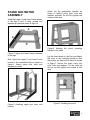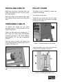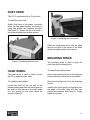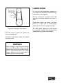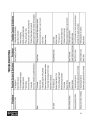
1
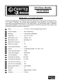
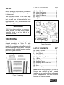
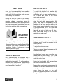
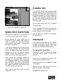
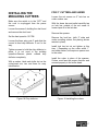
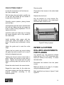
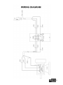
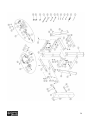
CX13 13” PLANER / MOULDER User Manual TABLE OF CONTENTS General Safety Instructions for Machines ............................................................... 3 Specific Safety Instructions..................................................................................... 4 CX13 Features........................................................................................................ 5 Physical Features ................................................................................................... 6 Set Up..................................................................................................................... 7 Un-Packing & Inventory .......................................................................................... 7 Proper Grounding ................................................................................................... 8 Assembly ................................................................................................................ 9 Stand & Motor ......................................................................................................... 9 Planer / Moulder......................................................................................................10 ON / OFF Switch.....................................................................................................10 Installing V-Belts ..................................................................................................... 11 Tensioning V-Belts.................................................................................................. 11 Pulley Cover ........................................................................................................... 11 Dust Hood............................................................................................................... 12 Hand Wheel ............................................................................................................ 12 Moulding Fence ...................................................................................................... 12 Test Run ................................................................................................................. 14 ON/OF Switch ......................................................................................................... 14 Depth of Cut............................................................................................................ 14 Thickness Scale...................................................................................................... 14 Work-Piece Inspection ............................................................................................ 15 Planing Tips ............................................................................................................ 15 Feed Rate ............................................................................................................... 15 Thickness Planing................................................................................................... 16 Moulding ................................................................................................................. 16 Installing the Moulding Cutters................................................................................ 17 In-Feed & Out-Feed Rollers Adjustment for Planing ............................................... 18 Setting the Feed Rollers for Moulding.....................................................................20 Making A Table Board ............................................................................................ 20 Maintenance ........................................................................................................... 21 Table Surface ......................................................................................................... 21 Knife Inspection ......................................................................................................21 Knife Replacement.................................................................................................. 22 V-Belts .................................................................................................................... 22 Lubrication .............................................................................................................. 23 Troubleshooting ...................................................................................................... 24 Wiring Diagram ....................................................................................................... 25 Parts Breakdown & Parts List...........................................................................26 – 34 Warranty ................................................................................................................. 35 2 GENERAL SAFETY INSTRUCTIONS FOR MACHINES Extreme caution should be used when operating all power tools. Know your power tool, be familiar with its operation, read through the owner’s manual and practice safe usage procedures at all times. ALWAYS read and understand the user manual before operating the machine. CONNECT your machine ONLY to the matched and specific power source. ALWAYS wear safety glasses respirators, hearing protection and safety shoes, when operating your machine. NEVER leave a tool unattended while it is in operation. NEVER allow unsupervised or untrained personnel to operate the machine NEVER reach over the table when the tool is in operation. ALWAYS keep blades, knives and bits sharpened and properly aligned. DO NOT wears loose clothing or jewelry when operating your machine. Wear protective hair covering. ALL OPERATIONS MUST BE performed with the guards in place to ensure safety. A SAFE ENVIRONMENT is important. Keep the area free of dust, dirt and other debris in the immediate vicinity of your machine. ALWAYS use push sticks and feather boards to safely feed your work through the machine. BE ALERT! DO NOT use prescription or other drugs that may affect your ability or judgment to safely use your machine. DISCONNECT the power source when changing drill bits, hollow chisels, router bits, shaper heads, blades, knives or making other adjustments or repairs. ALWAYS make sure that any tools used for adjustments are removed before operating the machine. ALWAYS keep bystanders safely away while the machine is in operation. NEVER attempt to remove jammed cutoff pieces until the blade has come to a full stop. 3 CX13 PLANER / MOULDER SPECIFIC SAFETY INSTRUCTIONS ALWAYS read and understand the user manual before operating the planer / moulder. ALWAYS feed stock smoothly. Do not force or twist the work-piece while planning. DO NOT plane materials such as plywood, hardboard, fiber board or any other material than solid natural wood fiber. DO NOT looks inside the planer / moulder while feeding the work-piece into the cutter head. ENSURE that all parts are assembled and adjusted properly before turning the planer / moulder ON. KEEP your fingers away from the infeed roller while feeding the stock into the cutter head. ALWAYS inspect your stock for nails, staples, pieces of stones or any other foreign material which is dangerous if comes in contact with the cutter head. DO NOT plane stock with loose knots. DO NOT removes more than 1/8” from the surface of the stock in a single pass. ALWAYS plane in the same direction as the grain of the wood. ALL GUARDS must be in place while operating the planer / moulder to ensure safety. MAKE SURE before making any adjustments, the switch is in the “OFF” position and the cord is un-plugged. NEVER LEAVE the planer / moulder unattended while it is running. DO NOT attempt to remove jammed pieces unless the power switch has been turned to the OFF position and cord is unplugged from the power source and the cutter head has come to a complete stop. ALWAYS make sure that the planer / moulder is in a stable position. DO NOT operate the planer / moulder using dull or damaged knives. MAKE SURE you have read and understood all the safety instructions in the manual and you are familiar with your planer / moulder, before operating it. If you fail to do so, serious injury could occur. WARNING The safety instructions given above can not be complete because the environment in every shop is different. Always consider safety first as it applies to your individual working conditions. 4 CX13 Planer / Moulder FEATURES MODEL CX13 – 13” PLANER / MOULDER As part of the growing line of Craftex woodworking equipment, we are proud to offer the CX13, a 13” Planer / Moulder. The Craftex name guarantees Craft Excellence. By following the instructions and procedures laid out in this user manual, you will receive years of excellent service and satisfaction. The CX13 is a professional tool and like all power tools, proper care and safety procedures should be adhered to. Motor ................................... 1-1/2-HP, 110-Volts, Single Phase, 60-Hz Power Transfer .................... Twin V-Belt Drive Bearings .............................. Lubricated and Shielded Table Size............................ 14-1/8” x 17-3/4” Max Depth of Cut................. Planing; 1/8” Max Depth of Cut................. Moulding; 3/4” Max Stock Thickness........... 6” Min Stock Length................. 12” Cutter Head Diameter.......... 2-5/8” Knives.................................. 3 High Speed Steel 13” x 5/8” x 1/8” Cutter Head Diameter.......... 2-5/8” Cutter Head Speed.............. 5000 RPM Cuts Per Minute................... 15000 Feed Speed; Planing ........... 24 FPM Feed Speed; Moulding ........ 12 FPM Cuts Per Inch; Planing ......... 52 Cuts Per Inch: Moulding ...... 104 Measurement Scale............. Inch & Metric Dust Port.............................. 4” Weight ................................. Approximately 218 lbs Warranty .............................. 3 Years 5 CX13 – 13” PLANER / MOULDER PHYSICAL FEATURES Dust Hood Hand Wheel Pulley Cover Moulding Fences Powdered Coated Paint Gear Box Thickness Scale ON/OFF Switch 1-1/2 HP Motor Legs 6 SETUP LIST OF CONTENTS Before setting up your machine you should read and understand the instructions given in this manual. A. B. C. D. E. F. The unpainted surfaces of this table saw are coated with a rust preventive waxy oil that you will want to remove before you begin assembly. Use a solvent cleaner that will not damage painted surfaces. QTY Upper Side Braces........................... Lower Side Braces........................... Upper End Braces............................ Lower End Braces............................ Legs E.............................................. Legs F.............................................. 2 2 2 2 2 2 WARNING CX13 is a heavy machine, do not overexert yourself. For safe moving method use fork truck or get the help of an assistant or friend. UNPACKING The machine is properly packaged and shipped completely in crates for safe transportation. When unpacking, carefully inspect the crates and ensure that nothing has been damaged during transit. Open the crates and check that the machine and the parts are in good condition. Figure-1 Inventory Figure-2 Inventory LIST OF CONTENTS G. H. I. J. K. L. M. N. O. P. Q. R. QTY Planer / Moulder............................... Dust Hood........................................ Hand Wheel ..................................... Hand Wheel Handle......................... Motor Mounting Bracket................... V-Belts ............................................. Pulley Cover .................................... Moulding Fence ............................... Moulding Fence Guide Rod ............. Switch .............................................. Motor................................................ Hardware Bag .................................. 1 1 1 1 1 2 1 2 1 1 1 1 NOTE: While doing inventory, if you can not find any part, check if the part is already installed on the machine. Some of the parts come preassembled with the machine because of shipping purposes. 7 PROPER GROUNDING Grounding provides a path of least resistance for electric current to reduce the risk of electric shock. Make sure the cord is plugged into a properly installed and grounded power outlet. To prevent electrical hazards, have a qualified electrician ensure that the line is properly wired. Make sure that the appliance is connected to an outlet having the same configuration as the plug. If an adaptor plug is used, it must be attached to the metal screw of the receptacle. It is strongly recommended not to use extension cords with your CX13. Always try to position your machine close to the power source so that you do not need to use extension cords. In case if you really find it necessary to use an extension cord, make sure the extension cord does not exceed 50-feet in length and the cord is 14-gauge to prevent motor damage. WARNING Improper connection of the equipmentgrounding conductor can result in a risk of electric shock. Check with a qualified electrician if you are in doubt as to whether the outlet is properly grounded. Figure-3 110-Volts Outlet for CX13 8 STAND AND MOTOR ASSEMBLY Attach the upper A and lower B side braces to the legs E and F using, screws and washers provided as shown in figure-4. Attach the leg assemblies together as shown in figure-6 using bolts, nuts and washers provided. Do not fully tighten the screws at this time. Figure-6 Attching the bracket to the stand Figure-4 Upper and lower braces attached to the legs Now, attach the upper C and lower D end braces to the assembled legs as shown in figure-5. Secure using nuts, bolts and washers provided. Figure-5 Attaching upper and lower end bracket motor mounting Lay the stand down on the floor and attach the motor to the mounting bracket so that the pulleys are beyond the stand as shown in figure-7. Secure the motor using four nuts, bolts and washers. Tilt the stand up and do not fully tighten the screws at this time. Figure-7 Installing the motor 9 PLANER / MOULDER Once the motor is mounted to the motor mounting bracket, it is then time to mount the planer / moulder onto the stand. Once you make sure the planer / moulder is properly mounted onto the stand, tighten all the bolts on the stand assembly which were finger tightend before. WARNING CX13 is a heavy machine, do not overexert yourself. For safe moving method use fork truck or get the help of assistants or friends. Place two boards under the cutter head of the planer / moulder and make sure that the boards are long enough to protrude from the planer / moulder at least 14” on both sides as shown in figure-8. ON/OFF SWITCH To mount the switch assembly: to the stand Put the female plug through the hole and attach the switch to the upper side bracket as shown in figure-9. Hold the nuts on the inside of the stand using a proper sized wrench and tighten the screws using a screw driver. Figure-8 Lifting the moulder Use a fork truck or get the help of assistants or friends to help lift the planer / moulder onto the stand. Make sure the holes on the stand top are aligned with the holes under the planer / moulder and using four screws and four washer provided. Figure-9 Installing ON/OFF switch Connect the male plug coming from the motor with the female plug coming from the switch. 10 INSTALLING V-BELTS PULLEY COVER Make sure the motor mounting bolts are loose, and install the belt onto the upper and lower pulleys. The pulley cover is installed to protect the V-belts from damage. To install the V-belt cover: Move the V-belt to the second pulley step and install the other V-belt on the first pulley step. Thread the two studs into the two holes located on the side of the planer / moulder and stand. See figure-11. TENSIONING V-BELTS To tension the V-belts pry the motor assembly using a strong wooden bar as shown in figure-10. Check the belt tension by pushing the Vbelt using your index finger and applying moderate pressure. If the V-belt deflects approximately 1/2", the belt is tensioned correctly. Hold the motor in place and tighten the motor mounting bolts to secure the motor in its place. See figure-10. Figure-11 Studs threaded into the holes Install the pulley cover on the studs. Secure it using knobs as shown in figure-12. Figure-10 Prying the motor using a wooden bar Figure-12 Installing the pulley cover 11 DUST HOOD The CX13 is provided with a 4” dust hood. To install the dust hood: Attach dust hood to the planer / moulder, under the chip guard bracket and secure it using cap screws and washers provided. See figure-13. Secure the the dust hood to the planer/moulder from bottom as well. Figure-14 Installing the hand wheel Place the hand wheel lock onto the shaft through the hole in the center of the hand wheel and tighten with a screw driver. MOULDING FENCE Figure-13 Installing the dust hood The moulding fence is used to align the stock with the moulding knives. HAND WHEEL To install the moulding fence: The hand wheel is used to raise or lower the CX13 planer/moulder table. Secure the moulding fences to the clamping blocks with caps screws and lock washers. To install the hand wheel: Screw the locking knobs into the clamping blocks. Locate the shaft on the top part of the planer/moulder and slide the hand wheel on the shaft so that the pin on the shaft slides into the groove on the hand wheel as shown in figure-14. Installing the fence guide rod brackets onto the edge of the work table with four cap screws and washers. See figure-15. Finger tighten the screws. 12 Figure-15 Moulding fence and brackets Slide the fence rod between the brackets and thread the remaining cap screws, with flat washers and the lock washers, into the ends. Place the moulding fences over the fence rod and tighten the locking nob. Adjust the fence rod brackets until the fence lie flat on the surface of the bedboard or work table and tighten the cap screws. 13 TEST RUN Once you have assembled your machine completely, it is then time for a test run to make sure that the machine works properly and is ready for operation. During the test run if there is any unusual noise coming from the machine or the machine vibrates excessively, stop the machine immediately and disconnect from the power source and investigate if you can find out the problem with your machine. READ THE MANUAL Before starting the planer/moulder, make sure that you have read and understood the manual and you are familiar with the functions and safety features on this machine. Failure to do so may cause serious personal injury. ON/OFF SWITCH CX13 planer/moulder is equipped with a push-button switch that will accept a safety padlock (not included). To safeguard your machine from unauthorized operation and accidental starting by young children, the use of a padlock is required. DEPTH OF CUT To control the depth of cut, use the table height hand wheel to raise or lower the work table and you can read the depth of cut in inches and metric on the cutting depth scale provided. One revolution of the hand wheel lowers or raises the work table approximately 5/64” (2mm). The depth of cut depends on the hardness of the wood and the width of the board being passed under the cutter head. It is recommended not to cut more than 1/16” of the material in one single pass. Generally a series of light cuts will give a better result than trying to cut too much material in a single pass. THICKNESS SCALE In order to get accurate results, the thickness scale should be adjusted at the correct position. To adjust the thickness cale: Take a pre-planed board and measure the thickness with a caliper. Use the hand wheel and raise the work table so that the cutter head is 1/16” under the thickness of the board. Feed the board under the cutter head. Rotate the hand wheel half way and feed the board into the cutter head. Measure the board again and compare the thickness of the board with the result on the scale. If you find the measurement wrong, simply loosen the screw on the scale pointer and adjust the pointer to the correct. See figure-16. 14 PLANING TIPS For improved surface finishing with minimal tearouts, always feed the work-piece with the grain. The work-piece should be fed into the planer/moulder so that the blades are travelling with the grain as they finish the cut. The grain should be angled up towards the rear of the work-piece as it is fed into the cutter head. Do not remove more than 1/16” of material in a single pass. Figure-16 Thickness scale pointer WORK-PIECE INSPECTION This planer is designed to cut wood only, do not cut any kind of metal, stone or glass. Before planing the stock, make sure to inspect it for nails, staples, small pieces of stone or metal and any other foreign objects which could come in contact with the cutter head knives. If the wood contains any of these objects and it comes in contact with the cutter head knives, the object might cause kick back or damage the knives. For optimum results, always inspect your work-piece carefully before you cut and wear eye protection. Some woods with excessive twisting or wrapping are un-stable while cutting and are dangerous because during operation the work-piece can move unexpectedly which will either damage the blade or injure the operator. One face of the twisted stock should be surfaced on a jointer. Some stocks with large knots are also dangerous to cut. If you are planing long lumber, get the help of an asssistant or use a roller stand to provide support for the work-piece. Plan the stock at 12 FPM for a smoother and better finish. FEED RATE CX13 planer/moulder features two speeds to feed the work-piece into the cutter head; 12 FPM for improved surface finish when molding and 24 FPM for faster planing. To change the Feed Rate: Un-plug the cord from the power source and make sure the switch is in the “OFF” position. Loosen the nut securing the gears cover and remove the gearbox cover. Loosen the idler hex nut holding the gears on the shafts. Remove the two cap screws and put the other set of gears on the shafts. Retighten the gearbox cover. 15 Raise the work table to a maximum of 1/16” and flip the stock and feed the stock up side down into the cutter head so that the other side of the board is planed with the grain. Measure the thickness of the board and keep planing in the same manner untill you get the required thickness. Figure-17 Feed rate gears MOULDING Moulding with professional results takes planning prior to starting. THICKNESS PLANING The thickness planning creates a smooth surface parallel to the opposite side of the board. It does not eliminate twisting and cupping. If the board has twisting or cupping, joint it on a jointer before planing. To perform thickness planing: Use the hand wheel to raise or lower the table to achieve the depth of cut required. Remember not to cut more than 1/16” of the material in one single pass. Turn the planer “ON” and stand to the side, grasping the work-piece in the center of the table. Support the in-feed end of the board untill half of the board has been fed into the cutter head, then walk around to the outfeed side and support the other end. Always take a light cut for the smoother finish. Pre-sizing wood before moulding is necessary. Always pre-size the work-piece to 1/16” of the final thickness before running the work-piece through the moulder. With profiles that require outer edge cleanup, the work-piece should be 1/8” larger than the final width allowing 1/16” on either side of the cutter. With profiles that only cut the edge of the work-piece, the work-piece should be the same size as the final width. Other considerations before moulding to consider are wood hardness, moisture content , degree of warp and direction of grain. 16 INSTALLING THE MOULDING CUTTERS Make sure the switch in in the “OFF” and the cord is un-plugged from the power source. Loosen the screws A holding the dust hood and remove the dust hood. Set the feed speed to 12 FPM. Loosen the three wing nuts C and slide the curved in-feed chip deflector D out fo the way. Tighten screws to hold the chip deflector in place, it is not used in the molding operation.Remove plastic outfeed chip deflector completely. With a marker, label each knife slot on the cutter-head one, two and three for easy identification. Figure-18 Chip deflector FOR 2” CUTTERS AND UNDER Loosen the set screws on 2” lock bar on cutter number one. With the brass bar and mallet carefully tap on lock bar outside of the set screw to loosen taper fit to the lock bar. Remove the spacers. Remove the lock bar, (with 2” wide and under moudling cutters, the planing knives remain in place). Install lock bar but do not tighten at this time. ( Depending on the cutter width, 1” and under cutters, will require a spacer next to the cutter. Install the cutter in place of the spacers. Cutters must face the proper direction and secured properly in the cutter-head. Figure-19 Installing the cutters 17 FOR CUTTERS OVER 2” Remove guide. Loosen the set screws on all lock bars on the cutter number one. Check that all set screws in the cutter-head are tight. With the brass bar and mallet, carefully tap on the lock bar outside the set screws to loosen the lock bar taper fit. Replace the dust hood. Carefully remove spacers, planing knives and lock bars. Run the machine for a few minutes. Retighten the gib screws in the cutter-head. Re-check after 2 hours of use. Install special lock bars that is included with the knife set. Make sure the set screws are loose to allow locking adjustment. Do not tighten at this time. Install the cutter and make sure it is facing the proper direction and is fully seated in the cutter-head. Install moulding cutter gauge with hex socket cap screw and tighten to hold in place. The guide may be attached to either side. Adjust the guide end to meet the cutter edge. Tighten the hex socket cap screw holding the guide bar and be careful not to more it during the alignment process. Tighten lock bar set screw to hold cutter in place. Tighten set screws to hold cutter in place . Tighten set screws half turn each side to uniformly raise the lock bar until it is tight. Figure-20 Using L-gauge INFEED & OUTFEED ROLLERS ADJUSTMENTS FOR PLANING As a general rule, the infeed and outfeed rollers are set 1/8” to 3/16” below the cutter head (not knives) at the factory. To check the feed rollers: Disconnect the machine from the power source. Rotate the cutter-head to the second cutter. Repeat the same steps for the cutter two and three making sure that the cutters are properly positioned according to the alignment guide. Make two blocks out of scrap 2 x 4 lumber using the dimensions stated. Mark each block as shown in figure-21 and figure-22 . 18 Adjust the table height so the block can be inserted between the table and the cutter head with minimum resistance. Remove the block. Do not raise or lower the table at this point. It will affect the final result. Insert the block labeled "Feed Rollers Planing" into the planer opening. Raise or lower the feed roller until it rests on top of the block end to end. To adjust the feed roller, See figure-23. Figure-21 Feed roller planing Figure-23 Adjusting the feed rollers With the wrench provided, loosen the jam nut on both sides of the in-feed roller. Figure-22 Cutter head Lower the work table to allow the cutter head block to slide freely between the table and the cutter head. Note: the cutter head may have to be turned by hand to rotate the blade out of the way. Turn the threaded bushing counter clockwise to raise the roller and clockwise to lower roller. Raise or lower the roller until it contacts the top of the block on both ends of the roller. Block should slide in and out with a minimum force. Tighten jam nuts and re-check. Repeat this process with the out-feed roller. 19 SETTING THE FEED ROLLERS FOR MOULDING The infeed and outfeed rollers will have to be lowered for most moulding operations. The amount of adjustment required will vary depending on the size and style of the cutter. When using cutters larger than 2” wide, the feed rollers will have to be set 5/16” below the cutter head. To set the feed rollers for moulding: Following the method for setting the feed rollers when planning (previously explained in this manual), make another wooden block 5/16" lower than the cutter head block. See figure-24. Adjust the in-feed and out-feed rollers in the same manner as setting the rollers for planing using this new block. Label this block "feed roller molding". Save the block for future use. IMPORTANT When using molding knives wider than 2", the first pass or cut will remove approximately two thirds of the stock. Test cuts on scrap material will determine the number of passes required to complete the cut. Never attempt to completed cut with less than two passes on smaller knives (under 2") and three passes on larger knives (over 2"). Generally the more passes the better the finish. Due to variety of cutters available, it is impossible to cover every possible set-up. It is very important to perform test cuts on scrap material before attempting cut on project materials. IMPORTANT Board is 12” longer than the table to allow overhang (6” front and rear). This increases the work surface for longer pieces of wood stock. MAKING A TABLE BOARD Turn the machine OFF and unplug the cord from the power source. Cut a piece 3/4" particle board 12-7/8” wide and 31-1/4” long. Figure-24 Feed roller moulding Mark and drill four 1/4” holes on the bed board that match the pre-drilled holes on the planer/moulder table. Countersink the four drilled holes on the top side to allow installaion of countersunk screws. 20 Secure the bedboard to the table with four 3/16” x 1-1/2” flat hed machine screws, four 3/16” x 3/4” washers and four 3/16” hex nuts. KNIFE INSPECTION Turn the switch OFF and disconnect the machine from the power source. Remove the dust hood and expose the cutter head. IMPORTANT It is necessary to use a table board when moulding. It prevents the moulding knives from hitting the table and dammaging the cutter head and the work table. Loosen the set screws holding the knife to the cutter head. Tap the gibs down into the cutter head, using a small piece of wood. Place a knife setting jig over the knife on the cutter head. See figure-25 MAINTENANCE During the life of your machine, you will need to practice some regular maintenance to keep your saw in peak performance condition. WARNING When installing / removing and servicing any part of the machine, make sure the power switch is in the off position and the cord is disconnected from the power source. Failure to do so may result in serious personal injury or death. Figure-25 Knife setting jig placement Adjust the jack screw until the knife makes contact with the knife setting jig on both ends. Hold the knife setting jig in position and tighten the knife locking screws in the cutter head. TABLE SURFACE The moisture from the wood dust remaining on the table surface can cause rust. The table and other un-painted surfaces of the machine should be cleaned and wiped after every use to make sure that there is no moisture against bare metal surfaces. Inspect the other two knives in the same manner. Make sure all the screws are tightened properly. 21 KNIFE REPLACEMENT Make sure the machine is turned OFF and the cord is un-plugged from the power source. end screws first and then the center screws until the knife is securely held in the cutterhead. Tighten the remaining two knives in the same manner. Remove the dust hood and expose the cutter head. To remove the knives, loosen the knife locking bar by turning the knife locking screws and remove the knife locking bar, knife and springs located under the knives. Remove the remaining three knives in the same manner. Clean the knives slots, locking bars, springs and locking screws. When changing your knives, inspect to ensure the knives do not have any nicks, cuts or wire edges. Hone the knives slights using a stone or honing guide. Place the knife gauge over the knife and while holding down, loosen all six locking screws by turning them into the locking bar until the cutting edge of the knife comes into contact with the protrusion of the gauge. Now snug up the knife locking bar by slightly backing out the screws against the slot. The knife gauge should touch all three points of the roller and knife. Replace and reset the other three knives in the same manner. All three knives are set with the screws just snug back and tighten the screws against the slot starting with the V-BELTS The V-belts stretch with use and needs to be checked and tensioned properly as the planer/moulder is used. Turn the machine OFF and un-plug the cord from the power source. Remove the knobs holding the pulley cover and remove the pulley cover. Check the V-belts for crackes, fraying or wear. TO REPLACE THE V-BELTS: Loosen the motor mouting bolts and pivot the motor and remove the V-belts. Install the new belts onto the pulleys and rotate the pulleys to roll the belts into place. Pry the motor assembly and tension the Vbelts. There should be approximately 1/2" defelection when moderate finger pressure is applied on the middle point of the V-belt. 22 LUBRICATION For long life and trouble-free operation of your planer it is important to lubricate some components of the machine. The four columns of the planer should be lubricated, using light machine oil once in a week. Clean away debris and grime, and then brush on a light coat of multi-purpose grease to the feed roller chain and gears. Figure-26 Checking V-belt tension The table height adjustment chain should be inspected monthly and lubricated with general purpose grease when needed. Hold the motor in place the tighten the motor mounting bolts. Check the V-belt tension again and reinstall the pulley cover. WARNING When installing / removing and servicing any part of the machine, make sure the power switch is in the off position and the cord is disconnected from the power source. Failure to do so may result in serious personal injury or death. 23 24 25 CX13 PARTS BREAKDOWN 26 27 28 CX13 PARTS LIST 29 30 31 32 33 34 WARRANTY CRAFTEX 3 YEARS LIMITED WARRANTY Craftex warrants every product to be free from defects in materials and agrees to correct such defects where applicable. This warranty covers three years for parts and 90 days for labor (unless specified otherwise), to the original purchaser from the date of purchase but does not apply to malfunctions arising directly or indirectly from misuse, abuse, improper installation or assembly, negligence, accidents, repairs or alterations or lack of maintenance. Proof of purchase is necessary. All warranty claims are subject to inspection of such products or part thereof and Craftex reserves the right to inspect any returned item before a refund or replacement may be issued. This warranty shall not apply to consumable products such as blades, bits, belts, cutters, chisels, punches etceteras. Craftex shall in no event be liable for injuries, accidental or otherwise, death to persons or damage to property or for incidental contingent, special or consequential damages arising from the use of our products. RETURNS, REPAIRS AND REPLACEMENTS To return, repair, or replace a Craftex product, you must visit the appropriate Busy Bee Tools showroom or call 1800-461-BUSY. Craftex is a brand of equipment that is exclusive to Busy Bee Tools. For replacement parts directly from Busy Bee Tools, for this machine, please call 1-800-461-BUSY (2879), and have your credit card and part number handy. All returned merchandise will be subject to a minimum charge of 15% for re-stocking and handling with the following qualifications. Returns must be pre-authorized by us in writing. We do not accept collect shipments. Items returned for warranty purposes must be insured and shipped pre-paid to the nearest warehouse Returns must be accompanied with a copy of your original invoice as proof of purchase. Returns must be in an un-used condition and shipped in their original packaging a letter explaining your reason for the return. Incurred shipping and handling charges are not refundable. Busy Bee will repair or replace the item at our discretion and subject to our inspection. Repaired or replaced items will be returned to you pre-paid by our choice of carriers. Busy Bee reserves the right to refuse reimbursement or repairs or replacement if a third party without our prior authorization has carried out repairs to the item. Repairs made by Busy Bee are warranted for 30 days on parts and labour. Any unforeseen repair charges will be reported to you for acceptance prior to making the repairs. The Busy Bee Parts & Service Departments are fully equipped to do repairs on all products purchased from us with the exception of some products that require the return to their authorized repair depots. A Busy Bee representative will provide you with the necessary information to have this done. For faster service it is advisable to contact the nearest Busy Bee location for parts availability prior to bringing your product in for repairs. 35