1
2.12 Internal Hardware Delays
Delays from Changing Attenuation
The pulse sequence statement power, which is used to change the level of attenuation
produced by a 63-dB rf attenuator in the system, leads to the following values:
• On UNITYINOVA, 1 AP bus instruction, 0.5-µs concomitant internal delay (WFG start
takes 1 AP bus instructions at 0.5 µs and extra board delay of 0.75 µs, total 1.25 µs).
• On MERCURY-VX and MERCURY, 4 AP bus instructions, 4.8-µs concomitant internal
delay.
• On UNITYplus, 2 AP bus instructions, 2.3-µs concomitant internal delay (WFG start
takes 5 AP bus instructions at 5.75 µs).
• On VXR-S and UNITY, 2 AP bus instructions, 4.3-µs concomitant internal delay
(WFG start takes 7 AP bus instructions at 15.00 µs).
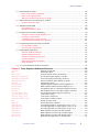
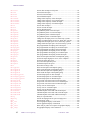
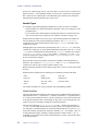
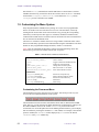
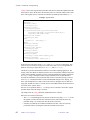
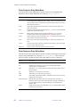
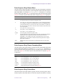
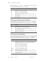
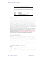
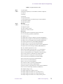
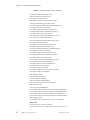
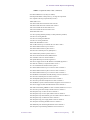
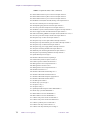
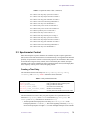
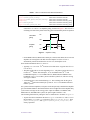
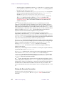
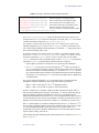
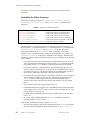
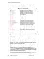
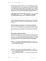
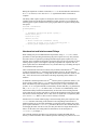
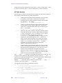
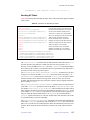
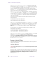
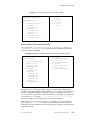
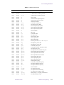
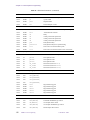
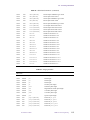
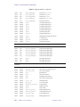
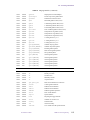
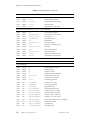
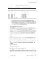
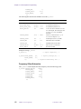
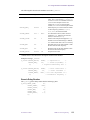
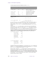
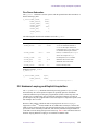
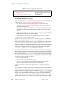
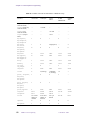
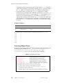
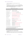
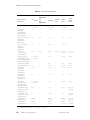
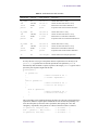
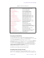
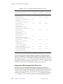
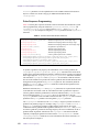
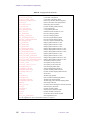
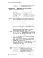
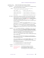
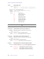
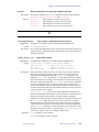
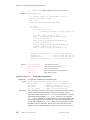
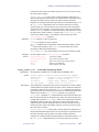
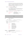
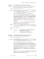
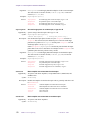
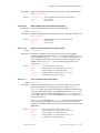
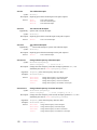
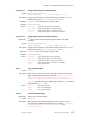
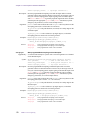
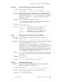
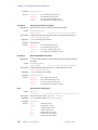
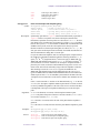
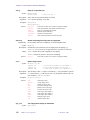
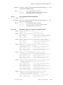
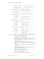
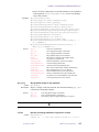
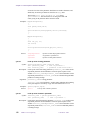
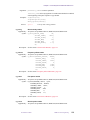
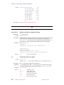
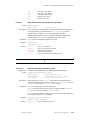
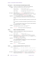
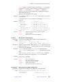
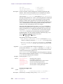
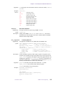
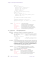
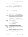
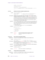
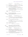
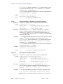
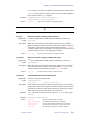
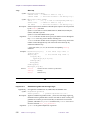
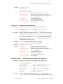
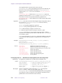
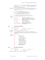
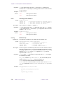
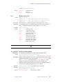
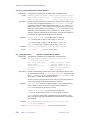
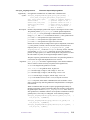
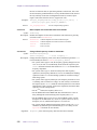
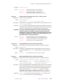
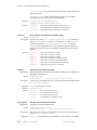
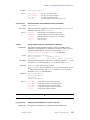
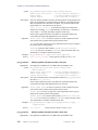
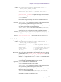
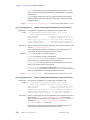
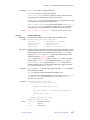
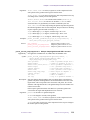
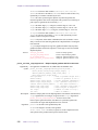
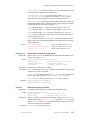
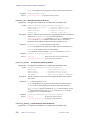
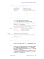
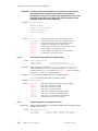
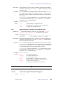
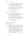
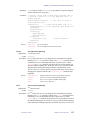
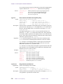
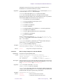
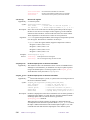
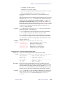
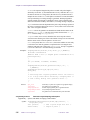
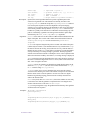
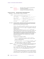
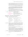
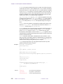
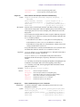
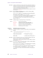
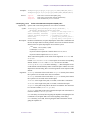
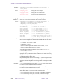
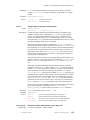
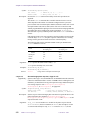
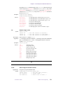
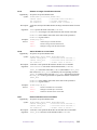
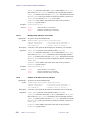
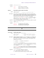
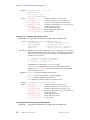
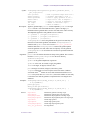
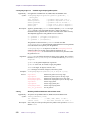
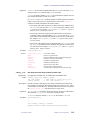
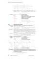
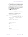
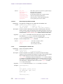
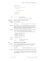
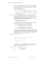
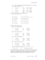
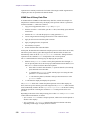
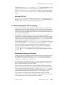
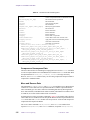
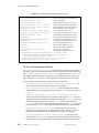
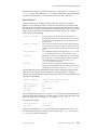
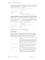
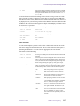
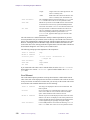
Table 32 lists all pulse sequence statements that lead to an internal delay and the magnitude
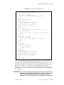
of this delay. Similar information to the table is contained in the PSG header file
apdelay.h, which resides in the VNMR system PSG directory.
On systems with the Output board, Table 32 indicates that the pulse sequence statement
power incurs a 4.5 µs internal delay, not a 4.3 µs delay as previously stated. Of the 4.5 µs
delay, 0.2 µs is to allow any high-speed line, (for example, the transmitter gate control line)
that has been turned off in PSG at the end of the preceding delay to actually turn off in
hardware before the AP bus instructions have been issued from the FIFO. Otherwise, any
such high-speed line would not be turned off in hardware until the end of the series of AP
bus instructions. This extra 0.2 µs delay can be avoided with the apovrride statement.
Delays from Changing Status
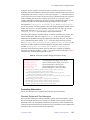
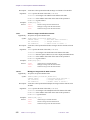
Other delays can be incurred with the status and setstatus statements. The first
occurrence of the status statement always incurs the full delay. On subsequent
occurrences of status, the delay depends on values of the parameters dmm, dmm2, and
dmm3. There are three parts that contribute to this delay:
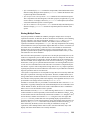
• Modulation mode – On UNITYINOVA, if and only if the modulation mode changes, 1.0
µs is added to the delay, and the first occurrence of 's' in the dm string (or dm2 or
dm3) adds an extra 1.0 µs. On systems with apinterface=3 or UNITYplus
systems, if and only if the modulation mode changes, 2.3 µs is added to the delay on
UNITYplus (4.3 µs on other systems). On UNITYplus only, if the mode is
synchronous, the first occurrence of the 's' in the dm string (or dm2 or dm3) adds an
extra 2.3 µs when the modulation mode is switched from CW to synchronize the
decoupling scheme. Note that the waveform generator (mode 'p') needs CW
modulation (mode 'c').
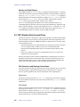
• Waveform generator – Starting a waveform generator adds 1.25 µs on UNITYINOVA,
5.75 µs on UNITYplus, and 10.75 µs on other systems. Stopping a waveform generator
adds 1 µs on the UNITYINOVA, 2.3 µs on UNITYplus, and 4.3 µs on other systems. (The
modulation mode is to or from 'p'.) The waveform generator also has an offset or
propagation delay, which is discussed below.
• Modulation frequency – If the modulation frequency changes, 1 µs is added on the
UNITY
INOVA, 4.6 µs on the UNITYplus, and 6.45 µs on other systems. Note that for the
UNITY
INOVA, and UNITYplus, this is different for a shaped pulse. The modulation
frequency can change if the statement setstatus is called with a modulation
frequency different from the parameter corresponding to the transmitter set, or if the
modulation mode changes to or from 'g' and 'r'. If the change is to 'g' and 'r',
the modulation frequency is internally scaled, changing the frequency.
01-999165-00 A0800
VNMR 6.1C User Programming
143