1
Contents
APPENDIX A
Connector Pinouts A-1
Vision MINI Smart Camera Connectors A-2
APPENDIX B
Cable Specifications B-1
61-000208-01 USB Type A to USB Type B Plug Cable B-2
61-000105-01 Host Cable, MS-Connect 210 to Host, Stripped to 9-Pin
Socket B-3
61-000196-02 Vision MINI USB / I/O Cable (Attached) B-4
61-300026-03 Communication Cable, DB25 Plug to DB9 Socket B-6
97-000012-02 Power Supply, 90-254 VAC, 24VDC, USA/Euro Plug B-7
99-000017-01 Photo Sensor, Visible, NPN, Dark On B-8
99-000017-02 Photo Sensor, Visible, NPN, Light On, MS-Connect 210
Configuration B-9
APPENDIX C
General Specifications C-1
Vision MINI Smart Camera General Specifications C-2
Dimensions C-7
Field of View and Working Distance C-8
APPENDIX D
Serial Commands D-1
APPENDIX E
Vision MINI Diagnostic Boot Mode E-1
APPENDIX F
USB Power Management F-1
v
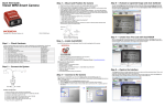
Vision MINI Smart Camera Guide