1
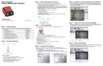
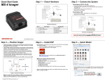
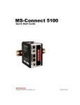
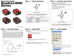
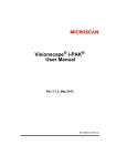
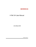
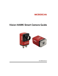
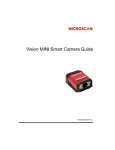
Quick Start Guide
Step 3 — Mount and Position the Camera
Vision HAWK Smart Camera
Copyright ©2011 Microscan Systems, Inc.
1. Position the camera at a focal distance of one inch or more from a test object.
2. Tip the camera relative to the object to avoid the glare of direct (specular) reflection. The case parting
line should be perpendicular to the plane of the symbol by either pitching the symbol or the camera
as shown. Avoid excessive skew or pitch. Maximum skew is ±30°; maximum pitch is ±30°.
Proper lighting is critical to the success of a machine vision application. The Vision HAWK features
integrated high-output lighting (.564mW, 617nm). Depending on the requirements of your application,
you may also need to add external lighting from Microscan’s NERLITE family of machine vision lighting products.
Consider the following:
• Is the surface of the object flat, slightly bumpy, or very bumpy?
• Is the surface matte or shiny?
• Is the object curved or flat?
• What is the color of the object or area being inspected?
• Is the object moving or stationary?
Machine vision lighting should maximize contrast of the areas or features being inspected while
minimizing the contrast of everything else.
Step 6 — Evaluate a Captured Image and Auto Calibrate
You will see the Image view after selecting your device. This view allows you to evaluate your first image
capture, providing information such as image size and a histogram. Click the Auto Calibration button to
set optimal camera parameters automatically. You can also adjust Exposure, Gain, and Focus as needed,
and set the desired Lighting Mode.
P/N 83-126800 Rev A
Camera / Object Positioning
Step 4 — Install AutoVISION
Step 1 — Check Hardware
Step 7 — Create Your First Job with AutoVISION
After you have evaluated a captured image and Auto Calibrated the camera in the Image view, you will
move to the Create view. This interface allows you to set camera parameters, add machine vision tools to
captured images, set tool parameters, and configure I/O inspection outputs.
AutoVISION can be found on the Microscan Tools Drive that is packaged with the camera.
The list of hardware below can be used in a variety of applications and configurations. Consult with
Microscan for further information about which items are most appropriate for your application.
Item
Description
Part Number
1
Vision HAWK Smart Camera
GMV-6800-XXXXG
2
QX-1 Interface Device
98-000103-01
3
Cordset, Common, M12 12-pin Plug to M12 12-pin Socket, 1 m
61-000162-01
4
Cordset, Host, Serial, M12 12-pin Plug to DB9, 1 m
61-000152-01
5
Cordset, Host, Serial, M12 12-pin Socket to DB9, 1 m
61-000153-01
6
Power Supply, M12 12-pin Socket, 1.3 m
97-000003-01
7
Cordset, Host, Ethernet, M12 8-pin Plug to RJ45, 1 m
61-000160-01
8
Trigger, M12 4-pin Plug, NPN, Dark On, 2 m
99-000020-02
Note: Additional cordsets available in the Microscan Product Pricing Catalog.
Step 2 — Connect the System
1
1. Follow the prompts to install AutoVISION from the Tools Drive.
2. Click on the AutoVISION icon to run the program.
Note: AutoVISION can also be installed from the Download Center at www.microscan.com.
Minimum System Requirements
• Core2Duo processor
• Windows 7 32-bit or XP operating system
• Internet Explorer 7 or higher
• 2GB RAM/128MB Video RAM (Windows 7); 1GB/128MB Video RAM (XP)
• 750MB to 1GB hard drive space
• 16-bit color display
• 3.0 Windows Experience Index (4.0 preferred)
Step 5 — Connect to the Camera
3
7
2
6
8
Ethernet Configuration
1.
2.
3.
4.
5.
6.
Mount the camera (1) as required by the application.
Connect the Ethernet Cordset (7) from “B” on the camera (1) to the network.
Connect the power supply (6) to “3” on the QX-1 (2).
Connect the trigger (8) to “T” on the QX-1 (2).
Connect the “Common” Cordset (3) to “2” on the QX-1 and “A” on the camera.
Plug in the power supply (6).
After you launch AutoVISION, you will see the Select a device to start editing a job view.
Note: If there is a default job on the camera, AutoVISION will automatically skip the Connect step and you
will see the Image view.
1. Select your camera from the Select Device dropdown menu.
2. Click the Modify button beneath the camera settings details to change camera settings.
3. Choose whether you want to create a new job, load a job (.avp) from your PC, or upload a job from
the camera.
Step 8 — Explore the Interface
The Create view features a large image area with tool icons above and tool parameters below. When a tool
is selected, its parameters appear below the image area.
Tools that have been added are shown in the job list to the left of the image area, below the Camera box.
Image settings can be controlled using the icons in the corners of the image area.
Step 9 — Set Camera Parameters
Step 12 — Run the Job
1. Click on the Camera box to the left of the image area.
2. In the camera parameters below the image area, select the desired type of Trigger, Trigger Polarity,
Photometry (Exposure and Gain), Focus, and Lighting.
When all job parameters are set, click on the Run step at the top of the interface. The software will download the
vision job just created to the camera and will begin the inspection. Inspection results and the list of active tools
are shown at the right of the image view. That information can also be moved below the image area by
clicking the orientation buttons above the inspection results area.
Power Requirements and Pin Assignments
CCD Power Requirements: 5-28VDC, 200mV p-p max ripple, 155mA at 24VDC (typ.), 14.5 watts (max.)
CMOS Power Requirements: 5-28VDC, 200mV p-p max ripple, 125mA at 24VDC (typ.), 11.5 watts (max.)
Connector A on the back of the camera is a serial M12 12-pin plug.
Connector B on the back of the camera is an Ethernet M12 8-pin socket.
Output 2
Default
Learn
Terminated
TX (+)
Power
Output 1
Terminated
RX (–)
Host
TxD
Output 3
RX (+)
Trigger
Ground
Terminated
Host RxD
Input Common
TX (–)
Terminated
Output Common
A (Serial) M12 12-pin Plug
B (Ethernet) M12 8-pin Socket
QX-1 Interface Device
Step 10 — Add Tools to the Job
Test Jobs
1. Click on the Decode Tool or drag it onto the image area.
2. Use the anchor points at the corners of the region of interest to form a box around the Data Matrix
symbol. Leave plenty of space on each side of the symbol.
3. Now add a second Decode Tool and do the same for the 1D symbol below the Data Matrix symbol.
4. Finally, add an OCR Tool and drag the region of interest around the area of the image where “123456”
is printed.
Note: For descriptions of more advanced functionality, such as setting Inspection Outputs or using the
Locate Tool and Decode Tool’s Dynamic Locate functionality to track multiple tools from image to image,
see the help documentation in AutoVISION software or the AutoVISION User’s Manual.
Connector T on the QX-1 Interface Device is the trigger connector.
Connectors 1 and 3 are 12-pin plugs, and Connector 2 is a 12-pin socket. All three connectors can be
assigned to bus power and data as required by the application.
The two switches at the center of the device allow the user to route signals as needed.
This simple diagram (shown on the
base of the QX-1) illustrates how
power, communications, I/O, and
trigger signal can be routed through
the QX-1 device depending on the
needs of the application. The
switches greatly increase signal
routing flexibility.
P
Decode Tool, OCR Tool, Match Strings Tool,
String Format Tool
T
QX-1 Interface Device
QX-1 Communications I/O - Power - Trigger
Trigger
Ground
Measure Tool,
Count Tool
+10-28V
Trigger/New Master /
Input 1 Common
QX-1 Trigger Connector
4-pin Socket
Vision HAWK Accessories
Step 11 — Try Out the Job
Once you have configured the tools as desired, use the arrow icons in the Job area to try the job you have
just created.
Note: Most jobs will inspect multiple captured images. If only one image is being inspected, the effect of the
arrow icons will not be evident.
Try Out Job
Once
Try Out Job
in Loop
Adapter Plate Kit
98-000143-01
Right Angle Mirror Kit
98-000144-01
Window Replacement
98-000146-01
15° Lens Kit
98-000147-01
30° Lens Kit
98-000147-02
45° Lens Kit
98-000147-03
L-Bracket Kit
98-000148-01
Demo Kit
98-000213-01
Infrared (IR) Filter
98-000205-01
Glass Window Kit
98-000206-01
Demo Kit
98-000215-01
Microscan Tools Drive
37-000010-01
Note: Additional accessories are available in the Microscan Product Pricing Catalog.
Vision HAWK Part Numbers
Copyright ©2011 Microscan Systems, Inc.
Vision HAWK part numbers follow the format GMV-6800-CLSYG:
Comm = 1 for Ethernet, 2 for USB;
Lens = 0 for C-Mount, 1 for 15°, 2 for 30°, 3 for 45°;
Sensor = 0 for CCD, 1 for CMOS;
Y (Options) = 0 for AutoVISION, 1 for Custom, 2 for Licensed (Visionscape), 3 for Custom + Licensed
G = RoHS-Compliant