1
WIZnet iEthernet Design Contest 2007
Secure-Web-Based-Chrono-Thermostat
Entry
#001146
Entry #001146 - Ramón Rodríguez Luque
Secure Web-Based Chrono-Thermostat
DISTICTIVE EXCELLECE
Power cable
Power and Data cable
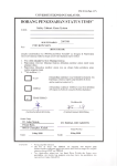
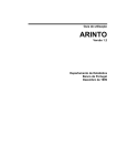
1. Overview
Temperature sensor
PoE extractor
adapter board
LCD display
Data Cable
WIZnet adapter board
Boiler cable
Switches
Figure 1.- Complete assembly.
A few years ago I bought a chrono-thermostat for my new house. I searched for a versatile
chrono-thermostat that I could use easily, but my quest proved unsuccessful, for if it was to be
really versatile then it would be very complex to use it.
I also wanted to switch on/off the boiler (electric kettle) at my work place, because usually I
don’t know what time I will finish work. I found one that allowed remote use of the chronothermostat, but it could only be done through the use of my by mobile phone, and it was rather
costly.
So when I though which project I would like to do for this Contest, I decided to design a device
that was suited to the use explained above.
I have a gas heating system at home so I speak about switch on/off my boiler because in order to
switch on/off my heating system, I will switch on/off my boiler. If the house does not use gas
for heating, its system will have an on/off switch for the system as a whole, and the chronothermostat could be connected to it.
Unlike most chrono-thermostats, this one wider possibilities:
•
Web-based control of the system. You can modify Target temperature, timers, etc.
1
WIZnet iEthernet Design Contest 2007
Secure-Web-Based-Chrono-Thermostat
Entry
#001146
•
Secure Access to the system by the web interface. You need to give the system a user
name and a password to access it. It is very important because the system will be
connected to the internet for remote access.
•
It makes an Automatic date and time setting-on at power up. This is made possible by
its connection to a time server on the Internet. The device has a list of addresses to
check, just in case a particular time server does not operate at the moment of power up,
so the system will check another one.
•
Web-based control of all internal parameters. You can modify network parameters: IP
address, IP Mask, Ethernet address (MAC), Gateway IP address and Web port used by
the http server machine.
•
Power the chrono-thermostat through the Ethernet copper wire (PoE = Power over
Ethernet). Therefore it is not necessary to have a High Power supply (110/220V) in the
installation place.
•
Flash memory to save the configuration parameters.
•
Restoration of default parameters at power up pressing the mode button.
•
Obviously it can adjust the home temperature at a configurable comfortable target
temperature.
•
We can configure up to three timers that permit automatic switch on/off the system at
the desired time. You can choose the ON time, OFF time, period target in temperature
and the days in the week (normally refers to days form Monday to Friday) to activate it.
•
The thermostat machine has a filter to the measured temperature to avoid possible
erratic conversion of the ADC. Also there is a configurable temperature threshold that
mimics hysteresis comportment and a configurable delay between one switch and
another that avoid the continue switching on/off of the boiler.
•
It has a simple human machine interface on a LCD display and a few switches, which
manages the system mode: manual on mode, manual off mode and timer- controlled
mode. Also you can modify the target temperature when the system is in the manual on
mode.
2. System Description
The following system block diagram will show all blocks that the Chrono-Thermostat system
has inside and the system environment, as well as the many possible functions.
2
WIZnet iEthernet Design Contest 2007
Secure-Web-Based-Chrono-Thermostat
Entry
#001146
First of all, let us look at the system environment. The system is wired to the home boiler by
two wires to switch on/off the boiler. So if the house is cold then the system will switch on the
boiler, or if the house is hot then the system will switch off the boiler.
The system knows the home temperature because it has a temperature sensor that registers
ambient room temperature.
We have so far described a simple thermostat, but we have a W5100 chip and we can connect
our Chrono-thermostat to the LAN (Home LAN) to connect to the Internet.
Figure 2.- Global System Block Diagram.
The Home LAN can be as simple as a twisted-pairs cable from the chrono-thermostat to a home
router, but we can have switches in the middle that are transparent to the data traffic (data flow).
3
WIZnet iEthernet Design Contest 2007
Secure-Web-Based-Chrono-Thermostat
Entry
#001146
The cable to the router, or switch, also supplies power to the chrono-thermostat using the
Power-over-Ethernet standard.
In the router NAPT (Network Address Port Translation) we will now configure the TCP port 80
to the chrono-thermostat IP. So we can connect to the chrono-thermostat with a browser writing
the chrono-thermostat IP from the Home LAN, or writing the home router public IP from the
Internet.
Nowadays Internet providers often give customers a dynamic IP, but this is not a problem
because most routers, when they power up and receive an IP, connect to a dynamic DNS
provider such as “no-ip.com” or “dyndns.org”.
You can do everything from the web interface irrespective of where you are. It is more powerful
than the usual local interface.
Now let’s take a look at the inside of the chrono-thermostat. There are two main inside
components: the W5100 chip and the microcontroller.
The microcontroller is a 16bit PIC, the PIC24FJ64. We had a choice from a large number of
devices, and this one does not have any unusual possibility. The W5100 performs the more
difficult task, which is the TCP, IP, Ethernet and MAC, so the microcontroller only needs to
have enough memory for the code, but not any special peripheral inside other than a ADC
converter and real time clock.
If the microcontrollers do not have an ADC there is other temperature sensor from the same
family that has a serial interface and allows not having an ADC inside the microcontroller.
If the microcontrollers do not have a real time clock we can use a free timer and its associated
interrupt routine for count the time and date.
I shall now go over the different blocks of the chrono-thermostat system:
The WIZnet module works with the communications and allows the rest of the circuit to
overlook this task.
There is a Time client that runs only at power up in the system. It makes a connection to a list
of time server to get an update of date and time. If the first time the server is down or the
connection fails, then it tries another one of the list.
We have a secure layer between the WIZnet and the http server. It consists of a user and
password authorization made using the standard html authorization method.
When a user requests access to a website, then he must type the user and the password in the
browser dialog window. The user computer browser encrypts both into a key that is sent with
the request.
If the key is correct then an html server (web server) will supply the website. There are a lot of
sites to surf, like the main page with the date, time, temperature, target temp., system mode,
system status and boiler status. It can all be seen in the following figure.
There are also websites for:
4
WIZnet iEthernet Design Contest 2007
Secure-Web-Based-Chrono-Thermostat
•
•
•
•
•
•
•
Entry
#001146
Configuration of the three timers.
Configuration of network parameters.
Configuration of thermostat parameters.
Change of system mode.
Change of user name and password for system access.
Saving all system parameters onto a flash memory (Program memory of the
microcontroller).
Loading all system parameters from Flash memory.
Figure 3.- Web browser with the main page loaded.
There is a real time clock (RTC) for the measure of time in the system, but there is no battery
backup system to it. So when the system power is down, then the real time clock is off and its
time and date will be wrong, but when the system powers up, it uses the time client to set the
clock with the correct time and date.
The RTC feeds its data to a timer system to compare with the timer values and to switch the
system on/off. It also gives its data to the two human machine interfaces, the local interface and
the web interface.
The timer unit permits configuration of three switching program with eligible ON/OFF times,
active days in the week and target temperature. When the system mode is “timers” then the
system status is controlled by the timer unit.
5
WIZnet iEthernet Design Contest 2007
Secure-Web-Based-Chrono-Thermostat
Entry
#001146
The main objective is to build a thermostat so this block is obviously very important, but also
very easy. It has three system modes: timer controlled mode, manual on mode and manual off
mode.
When the manual mode is activated, the system status is modified by the human machine
interfaces, both local and web. However, in the timer controlled mode the system status is
function of the timer unit output.
If the system status is off then the boiler is off. Else the boiler switches on/off depending on the
home temperature, the target temperature and the time from the last switch on/off occurrence.
We have an Analog to Digital Converter (ADC) to convert the voltage from the temperature
sensor. This conversion is performed every second.
The ADC has an error of +/1bit so we place a simple filter between the ADC and the
thermostat. With the programmable filter we don’t see that the value of the temperature moves.
The filter formula is:
Temp(k) = Kpast · Temp(k-1) + Knew · Temp_form_ADC(k)
The temperature sensor is a MCP9700 sensor that gives a voltage proportional to the ambient
temperature. It gives 10mV/ºC. Also there is a driver relay to switch on/off the contacts from
the boiler.
The human machine local interface (HMLI) has a LCD display from an old NOKIA 3310
display that is widely used in the internet. I also use the LCD library from the
http://www.micropic.es/ and the PCB design from http://webs.ono.com/cucaracha/. I only need
to cut out a lot of very interesting functions and font tables, because I do not use them and I do
not have enough space for it.
The HMLI also has three buttons. One button allows change of the system mode, and the other
two allow changing the target temperature when the system is in manual mode.
It is a complex system because it has a lot of parameters, so it is very important to save these
values in a non-volatile memory. When the system powers up, then it gets all the parameters
from the flash memory.
The values saved may be wrong because an error on the part of the user. So there is a possibility
of rescuing the default values from the flash while the mode button is still pressed at power up
moment.
6
WIZnet iEthernet Design Contest 2007
Secure-Web-Based-Chrono-Thermostat
Entry
#001146
3. Hardware
Figure 4 .- Microchip 16-Bit 28-Pin Starter Development Board.
The prototype system was built around a Microchip 16-Bit 28-Pin Starter Development Board.
In addition to these, four other boards were manufactured. I wire the development board to the
others with “yellow prototype wires” in one case (LCD board), and with soldered wires to a
connector in the development board in others (Wiznet, Temperature sensor, relay and switches).
One board carries the graphic LCD. This printed circuit board make the pins of a Nokia 3310
LCD display accessible. The LCD display carry a PCD8544 (48x84 pixels matrix LCD
controller/driver) and the proper Liquid Crystal Display.
Figure 5 .- LCD display adapter board.
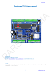
I made another board to interface the WIZ810MJ module that I received from the sample kit
requested. The adapter board has a connector with only the necessary pins to use the SPI
interface, so this connector has only eight pins. Also the interface board has a few LEDs to
7
WIZnet iEthernet Design Contest 2007
Secure-Web-Based-Chrono-Thermostat
Entry
#001146
indicate the RX, TX, FDX, LINK and COL conditions. It was very useful for the debugging
time.
Another mission of the wiznet adapter board is to use standard 0.1” pins, because the 2mm pin
to pin connector from the original wiznet board is very difficult to use in a debugging
development environment.
Figure 6 .- WIZnet adapter board.
Another important board carries the temperature sensor. It is a MCP9700 from Microchip. It’s a
low-cost, low-power sensor with an accuracy of ±2°C from 0°C to +70°C, but we can have an
accuracy of ±0.5°C by applying system calibration at 25ºC.
It is an analog temperature sensor that converts temperature to analog voltage. The analog
voltage is converted into a numeric value in the ADC of the microcontroller.
I made a PCB for this component only because it has a 5-Pin SC-70 footprint that it is very
difficult to manage. With this PCB I can reuse it in other prototypes. We can see this PCB in the
following figure.
Figure 7 .- Temperature sensor board.
Finally there is one relay and two switches, with its associated components, soldered in the
prototype board because it has a little area in its bottom to solder components into a pad matrix.
8
WIZnet iEthernet Design Contest 2007
Secure-Web-Based-Chrono-Thermostat
Entry
#001146
Figure 8 .- Relay and switches.
9
WIZnet iEthernet Design Contest 2007
Secure-Web-Based-Chrono-Thermostat
Entry
#001146
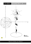
4. Circuit
The circuit is very simple. In the Figure 9 we can see the chart of the all components but the 16Bit 28-Pin Development board from Microchip.
There are two representations of the J2 connector from de development board. On the leftbottom there is a copy of the development board documentation. In the middle we have the
same block with the label of the pins adapted to the application.
We have a more readable copy of Figure 9 at end of the document.
Figure 9 .- Global System Schematic.
In the Figure 10 we can see the WIZnet module and how it interfaces with the circuit. We use
the SPI interface that permits enough speed for communication with the module, and it is simple
enough to have only a few pins in the microcontroller.
There are a power decoupling capacitor and a pull-up resistor to the SEN (SPI enabled) in the
adapter board.
10
WIZnet iEthernet Design Contest 2007
Secure-Web-Based-Chrono-Thermostat
Entry
#001146
Figure 10 .- Wiznet module.
There is a temperature sensor (MCP9700) to measure temperature. We see it in the Figure 11.
It has only three pins, two of them to power it, and a voltage output that is connected to the first
multiplexer ADC microcontroller input. It sinks its power from the analog power from the
development board.
Figure 11.- Development Board, Temperature module and LCD display module
There is no analog power in the connector, so I connect two wires in the bottom of the
development board.
In Figure 11 we can also see the LCD display module. It connects to the development board
with a serial interface. I do not use a SPI interface from the microcontroller because I used an
external library that makes the serial task through software.
11
WIZnet iEthernet Design Contest 2007
Secure-Web-Based-Chrono-Thermostat
Entry
#001146
The only one component in the LCD adapter board is a capacitor to the LCD bias power. The
LCD has inside a step-up voltage converter.
In Figure 11 we have the label in the J2 connector to the rest of connection.
In Figure 12 we have the rest of the components that are mounted directly on the development
board.
Figure 12.- Switches, crystal and relay.
We need to modify the development board because we need to have a real time clock. So I cutoff the two resistors R16 and R17 from the development board and I solder here the Y1 crystal
of 32768Hz. I also soldered the two 22pF capacitors (C2 and C3) in the bottom of the
development board.
We see these modifications in Figure 13.
The system needs three switches, but the development board has only one (SW1) playing the
role of ‘mode’ button. We add two low-level active switches (SW2 and SW3).
Finally we have a relay (K1) to drive the power wire from the boiler (J1 and J2). If the
microcontroller relay output is high the pin sources a current to the NPN transistor base and the
transistor drains a current from the collector circuit activating the relay.
Later, when the microcontroller relay output is low the pin does not source a current to the NPN
transistor base and then the transistor does not drain a current from the collector circuit, so the
relay discharges its energy to the D1 diode.
12
WIZnet iEthernet Design Contest 2007
Secure-Web-Based-Chrono-Thermostat
Entry
#001146
Figure 13.- Development Board Modificatons.
5. Software
I made all the software in ‘C’ language. I used the MPLAB IDE and the C30 compiler.
Initially my main objective was understand the WIZnet operation, so I made all function from
zero. From the low level function to write and read Wiznet register, to the high level code to
make an http server (web server) and a client TCP Time.
I only used external-made functions for the LCD control.
At power up the software read the flash memory, initialize all peripheral (Wiznet, LCD…) and
get the time and date from the internet.
Later there are three main tasks in the software:
1) Interrupt driven task (once per second).
13
WIZnet iEthernet Design Contest 2007
Secure-Web-Based-Chrono-Thermostat
Entry
#001146
It does the local interface attention updating the system values display and reading the
push button. Also it updates the temperature variable value and does the thermostat
function switching on/off the boiler.
2) Interrupt driven task (once per minute). It is synchronized with the real time clock for
execs when the minute change occurs. It reads the real time clock, updates the time
variables and process the timer function. Also it updates the display with the date and
time values.
3) Background task. It is the web server. It pays attention to the possible connections to the
web port that is listening by default. When there is a connection then it checks if the
authorization key is correct and if it is successful then it will send the requested page to
the client browser.
At power up the system executes the time client function for setting up its date and
time.
Figure 14.- Software block diagram.
We can now see a fragment of the source code here from the web server. It checks the
authorization and it transmits page/site selection:
void
http(char socket)
{
unsigned int offset, valor;
float
valor2;
char Rxdata, Valid=0;
char
fname[100], dummy[100], dummy2[100];
static char ch_pass_ok=0;
dummy[99] = 0;
dummy2[99] = 0;
size_of_received_data = read_size_RXBUFFER( socket );
for( offset=0; offset<size_of_received_data; offset++)
{
Rxdata = read_RXBUFFER( socket, offset );
Buffer[offset] = Rxdata;
}
// Mark end of buffer
Buffer[offset] = 0;
if( check_get_method( Buffer, &offset )==1 )
{
get_file_name( Buffer, &offset, fname );
14
WIZnet iEthernet Design Contest 2007
Secure-Web-Based-Chrono-Thermostat
Entry
#001146
/////////////////////////////////////////////////////////////////////////
// AUTHORIZATION Page -> Name and password checked but using Explorer Method
/////////////////////////////////////////////////////////////////////////
get_key_AUTHORIZATION( Buffer, size_of_received_data, dummy);
if( strcmp( dummy, KEY_AUTHORIZATION ) )
{
////////////////////////////////////////////////////////////////////////////
// ---------------------------------------------------------------------- //
// -------------AUTHORIZATION OK. ------------------------- //
////////////////////////////////////////////////////////////////////////
// Change Password Page -> Name and password required
////////////////////////////////////////////////////////////////////////
ch_pass_ok=0; // Don’t permit change password
if( (strcmp(fname, "change_password.htm" )==1 ) )
{
write_string_TXBUFFER( socket, WEB_CHANGE_PASSWORD );
ch_pass_ok=1; // Will permit change password
}
else if( strcmp( fname, "main.htm" ) )
// index -> Main
{
print_main(socket);
}
else if( strcmp( fname, "index.htm") | strcmp( fname, "") )
// index -> Frame
{
write_string_TXBUFFER( socket, WEB_HEAD );
write_string_TXBUFFER( socket, WEB_INDEX );
write_string_TXBUFFER( socket, WEB_TAIL );
}
else if( strcmp( fname, "top.htm" ) )
// TOP -> Title
{
write_string_TXBUFFER( socket, WEB_HEAD );
write_string_TXBUFFER( socket, WEB_TOP );
write_string_TXBUFFER( socket, WEB_TAIL );
}
…there is one “else if” for any possible page
…
else
{
/////////////////////////////////////////////////////////////////////////
// Page Don't Exist
/////////////////////////////////////////////////////////////////////////
write_string_TXBUFFER( socket, WEB_HEAD_ERROR );
write_string_TXBUFFER( socket, WEB_BODY );
write_string_TXBUFFER( socket, WEB_SORRY );
write_string_TXBUFFER( socket, WEB_TAIL );
}
// ---------------------------------------------------------------------- //
////////////////////////////////////////////////////////////////////////////
} // end if AUTHORIZATION OK
else
{
////////////////////////////////////////////////////////////////////////////
// ---------------------------------------------------------------------- //
// -------------AUTHORIZATION ERROR ------------------------- //
// AUTHORIZATION REQUEST.
if( ch_pass_ok==0)
{
write_string_TXBUFFER( socket, WEB_AUTH_RESPONSE );
}
// NEW PASSWORD REQUEST round 1.
else if( ch_pass_ok==1)
{
ch_pass_ok=2;
15
WIZnet iEthernet Design Contest 2007
Secure-Web-Based-Chrono-Thermostat
Entry
#001146
strcp( dummy, dummy2);
write_string_TXBUFFER( socket, WEB_CHANGE_PASSWORD );
}
// NEW PASSWORD REQUEST round 2.
else if( ch_pass_ok==2)
{
ch_pass_ok=0;
write_string_TXBUFFER( socket, WEB_HEAD );
write_string_TXBUFFER( socket, WEB_BODY );
if( strcmp( dummy, dummy2)==1 )
{
// The two keys are the same ---> OK
write_string_TXBUFFER( socket, WEB_CHANGE_PASSWORD_OK );
// Update the new KEY
strcp( dummy, KEY_AUTHORIZATION );
}
else
{
// The two keys aren't the same ---> ERROR
write_string_TXBUFFER( socket, WEB_CHANGE_PASSWORD_BAD );
}
write_string_TXBUFFER( socket, WEB_TAIL );
}
}
// end else
// ---------------------------------------------------------------------- //
////////////////////////////////////////////////////////////////////////////
} // end if check get method
// Clean the RX buffer
clear_RXBUFFER( socket, size_of_received_data );
// Close and open again the connection to listen to
restart_to_listen();
}
6. User manual
1
Installation
For installing the chrono-thermostat you must connect a cable from the nearest router or switch
to the installation place.
Place one of the PoE adapters close to the router and the other one close the chrono-thermostat.
It permits avoid the high power supply is in the installation place. This serves to avoid high
power supply in the installation place.
16
WIZnet iEthernet Design Contest 2007
Secure-Web-Based-Chrono-Thermostat
Entry
#001146
Figure 15.- Installation schematic.
PoE DEVICE POWERED
BY ETHERNET CABLE
CHRONO-THERMOSTAT
PoE
ADAPTER
PoE
ADAPTER
1
1
1
2
2
3
6
SWITCH/HUB/ROUTER
1
1
1
2
2
2
2
3
3
3
3
3
6
6
6
6
6
4
4
4
5
5
7
7
8
8
DATA PAIR
DATA PAIR
4
4
4
5
5
5
7
7
7
8
8
8
+VDD PAIR
5
7
-VSS PAIR
8
DC
DC
POWER SUPPLY
Figure 16 .- PoE schematic description.
17
WIZnet iEthernet Design Contest 2007
Secure-Web-Based-Chrono-Thermostat
Entry
#001146
Figure 17 .- Power over Ethernet, inyector adapter board, we can see in the figure 1 the extractor
adapter board.
Another cable from the boiler to the chrono-thermostat is required. This cable enables the
chrono-thermostat to switch the boiler on/off.
Boiler Relay
Boiler cable
Figure 18.- Boiler cable.
18
WIZnet iEthernet Design Contest 2007
Secure-Web-Based-Chrono-Thermostat
2
Entry
#001146
Web Interface
We must have a web browser to access to the chrono-thermostat. We will write in the browser
the chrono-thermostat IP if we are in home, but we will write the public IP from the router if we
try to access from outside the home.
The first answer from our chrono-thermostat is an authorization request page, like we can see in
the next figure. Then we must enter the user and password (by default: user=’admin’,
password=’admin’). Both the user and password can be changed.
Figure 19.- Authorization request.
When you are validated in the system, then you can see the main page (Figure 3.- Web browser
with the main page loaded.)
In the main page we can see the date, time, temperature, target temp, system mode, system
status and the boiler status.
In the left frame of the page you have a list of links to all the websites.
The next page that you can see is “THERMOSTAT CONFIG”.
19
WIZnet iEthernet Design Contest 2007
Secure-Web-Based-Chrono-Thermostat
Entry
#001146
Figure 20.- Thermostat config.
We can change the main thermostat parameters as the target temperature, only in the manual on
mode, because if the system mode is “timer” then the target in the timer is prioritized.
The Threshold is the maximum difference between the ambient temperature and the target
temperature without switching the boiler. So if you make this value lower then the boiler can
switch on/off frequently, but the ambient temperature would be closer to the target.
The other parameters are the filter parameters that represent the importance of the past and new
values respectively. The sum of two parameters must be one.
Finally we have the minimum time from switch to switch in the system for conservation of the
boiler life.
Next you have the three timer config pages.
When the page charge you can see the actual values of the timer parameters, then when you
press the apply button the data will be updated.
20
WIZnet iEthernet Design Contest 2007
Secure-Web-Based-Chrono-Thermostat
Entry
#001146
Figure 21.- Timer config page.
We have three timer programs but the priority is from 1 to 3, so the number one has the highpriority. If the three timers are active as the same time then the target temperature is the one that
has the most priority.
You can choose the on time, off time, target temperature for this period and which days of the
week it must be active.
Through the next link, “CHANGE MODE”, one may change the system mode from “timers” to
“manual” (on and off). The link reopens the main page to monitor the system status.
This is a networkable device so we need to can change the network parameters to adapting to
the environment installation. You can do it here.
We can see the default values in the following figure. The operative network parameters change
instantly; except for the web port none.
If you would like to permanently change the parameters for another power up you must press
the link “SAVE CONFIG” in order to write it in the flash.
Please bear in mind that if you change the IP address then you will not access the thermostat.
You must change your IP in the browser or, if the thermostat IP is in another network, then
change the computer IP.
The next link is “CHANGE PASSWORD”. You can change both the user and the password.
When you press the link pop-up a dialog window comes up, which is same authorization page
you connected to the very first time.
21
WIZnet iEthernet Design Contest 2007
Secure-Web-Based-Chrono-Thermostat
Entry
#001146
Figure 22.- etwork config page.
The only one difference with the authorization page is the label “Please enter the new User
Name and Password”.
YOU MUST INTRODUCE THE NEW USER NAME AND PASSWORD AND THEN, THE
DIALOG WINDOW WILL POP-UP AGAIN AND YOU WILL REINTRODUCE THE NEW
USER AND PASSWORD AGAIN.
This is the way to ensure that the user name and password are correct.
If you like to permanent change the parameters for another power up you must to press the link
“SAVE CONFIG” to write it onto the flash.
3
Local Interface
We can use the system locally, but we can only do the following:
1. Viewing operating values: Date, time, ambient temperature, target temperature, system
mode, system status and boiler status.
2. Changing the system mode. Pressing the “mode” button.
3. Modifying the target temperature (only in the “manual” system mode).
You can see the LCD display in the following figure.
22
WIZnet iEthernet Design Contest 2007
Secure-Web-Based-Chrono-Thermostat
Entry
#001146
Figure 23.- LCD display with all operating parameters.
There is one button to change the mode, another to increase the target temperature by a half
degree and finally another one to decrease the target temperature by a half degree.
7. Further Developments
I had a lot of ideas to make it, but the contest dead line is very soon, I haven’t enough time to do
it. There are many possible further ideas, but given the deadline I was not able to develop them.
BISTABLE RELAY.
In a bistable relay, after the input voltage is disconnected, the contacts remain in the last switch
position reached. It permits saving a lot of energy in the boiler on state because there would
only be power consumption in the boiler output changes.
All commercial chrono-thermostat use it because they are battery powered and they can’t power
a conventional relay with their batteries.
In our design we can use a conventional relay because we have a power supply, so we do not
have autonomy problems. But it is a problem related to the work environment.
MASTER-SLAVE ARCHITECTURE.
There are two WIZnet sockets free of use. So there is the possibility to use it to make another
interface to manage the chrono-thermostat from a home central server. We can use one for each
room that manages a water valve on a radiator and the central server boiler on/off switch.
This architecture permits have external web access to this central server and manage all chrono
thermostats.
23
WIZnet iEthernet Design Contest 2007
Secure-Web-Based-Chrono-Thermostat
Entry
#001146
SENSOR-BOILER-WEB SERVER ALTERNATIVE LINK.
May be a lot of problems in the practice to put a cable from the router to the chrono-thermostat,
also between the boiler and the chrono-thermostat.
One solution would be to divide the chrono-thermostat in three blocks:
1) Web server.
2) Sensor and Local Human Machine Interface.
3) Boiler Relay.
These three blocks can be connected together by a RF Link or a X-10 Link, but you need three
power supplies to the system, one to every block.
24
WIZnet iEthernet Design Contest 2007
Secure-Web-Based-Chrono-Thermostat
Entry
#001146
8. Global System Schematic
25