1
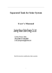
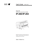
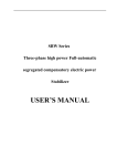
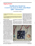
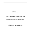
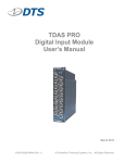
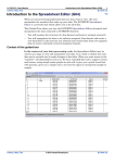
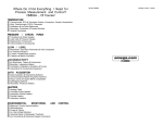
USER MANUAL – P13212 COLLISIONLESS RIMLESS WHEEL (WIRELESS) Team Members: Madhur Jain, Jason Bowerman, Robert DeWitte, Jeremy Benn, Phil Buchling ELECTRICAL SYSTEMS 1.1 Xbee Wireless configuration: The software associated with the Xbee Wireless microprocessor is called X-CTU and can be downloaded from the Digi website: http://www.digi.com/support/productdetail?pid=3352&type=utilities Once the X-CTU is downloaded, the first test is to see if the USB board is communicating correctly. Plug in the USB board with the Xbee installed and let the drivers automatically install. Open X-CTU and make sure all the parameters are correct by comparing them to Figure 1.1. It is important that the “Enable API” is not selected. After all the configuration parameters are set correctly, hit the “Test / Query” button with the correct Communications Port selected. A pop up should show up confirming a connection. Next, the transmit and receive actions should be tested on both Xbee chips. On the USB board, connect the transmit (Tx) and receive (Rx) pins together then select the terminal tab in the X-CTU program. Any letter you type will show up in blue and should be repeated in red. The blue indicates the character you typed and therefore transmitted, while the red indicates any received characters. Do the same test with the other Xbee chip making sure to unplug the USB cable before unplugging the Xbee chip. Finally, hook up the Xbee chip not attached to the USB board to a power supply using the pinout seen in Figure 1.2. All that is required for this test is the 3.3 supply voltage (Pin 1) the ground (Pin 10) and the Tx and Rx pins tied together. To test that the wireless communication is sent successfully test it in the same way as before by typing in the terminal. The blue still represents sent and the red received, but this time the data is sent from the computer through the USB board to the Xbee wirelessly to the other Xbee which in receives and transmits the same message back to the first Xbee and through the USB board to the computer terminal. Figure 1.1: Settings for the Xbee communication. Figure 1.2: Pinout for the Xbee wireless chip. 1.2 Microcontroller Connection with configure Figure 1.3: Microcontroller Break out Board Figure 1.4: Microcontroller Breakout Board Back Side The Microcontroller, control all of the data acquisition from the sensors and manipulated the data to be sent wirelessly. The breakout board could be power from the micro USB port or by power the 5V power rail. The breakout board included a voltage regulator that would step down the voltage from 5 volts to 3.3 volts. Controlling the system, interfacing, master of serial communication, and data manipulation was performed by the microcontroller. The microcontroller is a TI (Texas Instruments) ARM Cortex-M4F C2000. The experimental development board was attainted by participating in the Texas Instruments Analog competition the TI hardware was granted without cost. The processor selection process involved ensuring the digital outputs of the microcontroller were at 3.3 voltages and having on board flash memory could hold the required data for one trial. Another factor was the clock speed of the processor, speed chosen was 150MHz. The programming of the microcontroller took up the vast bulk of our time for this project. The prime 2 2 limitation on our time was programming the I C and SPI serial communication protocols. Implementing I C was a daunting task and after several weeks of little success the decision to attempt SPI was determined. After reviewing the sample code and libraries the verdict of switching serial protocols was justified. The interface between the MEMS sensors and the microcontroller followed the serial communication protocol of SPI. This option was left open because the sensors 2 chosen could connect either SPI or I C. SPI is a full duplex four wire or three wire serial communication protocol. Four wires were chosen because of the simplicity of execution. SPI has faster baud rates, but less slave acknowledgments 2 then its counterpart I C. Without the acknowledgment hand shaking between the slave and master devices the timing of SPI became crucial and trying to decipher the step in the serial communication was not clearly established. SPI serial protocol would be used to initialize the gyroscopes and configure their control registers. This serial connection likewise 2 would poll the two gyroscopes on two separate SPI buses. Additional benefits to applying SPI compared to I C are communication with full duplex, separate communication buses, and increased data rates. The serial interface between Zigbee wireless microchip and the TI microcontroller followed SCI or more commonly known as UART. The SCI serial communication protocol simpler to implement and lent the opportunity to demonstrate wireless communication before having complete control of reading the sensors. The ADCs proved to be facile to set up than the serial communication protocols, and therefore the analog potentiometer was first wireless data transmitted. The current and voltage readings were also received through the ADCs. The voltage potential coming from the battery was scaled and feed to the ADC on the microcontroller. The ADCs were also used to measure the current consumed by the motor and by the digital electronics downstream. The main current draw to the motor was subtracted by the current spent by the digital electronics. The voltage of the digital electronics was known because of the voltage regulator and hence this wasn’t required to be recorded. The ADC also delivers data from the potentiometer. The potentiometer data was received with 12 bits of resolution, ADC value would appear on the microcontroller scaled between 0 and 4095. All of the programs for the microcontroller are up on the edge site. Below is a link to the product for more information: http://www.ti.com/product/tms320f28335 1.3 H-bridge Connection with configure Figure 1.5: H-Bridge Pin Out Figure 1.6: Top View of H-Bridge Figure 1.5 shows the under side and pin out for the h-bridge motor controller. Figure 1.6 displayed above show the top side of the H-bridge for driving the motor. The functionality of the H-Bridge was simplistic the “PWMH” pin would drive the MOSFET transistor from off to saturation thus allowing the current to be dispated through the motor. The “PWMH” pin was driven by the microcontroller at 7.5 kHz and the duty cycle would be varing to control the speed of the motor. The “DIR” pin changes the direction of the motor, thus the motor brushede DC motor could be run in reverse. The “GND” pin is required to give the PCB board a reference for the pwm signal from the microcontroller. The “V+” pin the the board and the “GND” on the bottom right side was connected to the power source supplying the motor. The “OUTA” and “OUTB” pins feed the motor the power from the “V+” and “GND”. Below is a link to the product for more information: http://www.pololu.com/catalog/product/755 1.3 Gyro Connection with configure Figure 2.5: Gyro Pin Out The two MEMS Gyros used to find the angular velocity of the inner and outer wheels of the system had the pin out shown in the Figure 1.6. The “VIN” pin of the chip was a regulated 3.3 input to power the device. This pin was connected to the 3.3V supply on the microcontroller. The ”GND” pin was needed as a reference for the power and signal wires. The “SCL” pin was used in the SPI serial communication between the microcontroller and the sensor. The pin functioned in the serial communication protocol as the clock signal from the master (microcontroller), this is a necessity to synch the devices. The “SDA” pin on the chip also known as the master output slave input (MOSI) was connected pin 19 on the microcontroller. Since SPI is a full duplex serial interface the a separate line for the information to configure the device will be on this line. The “CTRL_REG1” on the sensor at address 20h was written to be configured to be 0Ch. This caused the device to wake up from sleep mode and for the device to start sensing the Z-axis velocities. “CTRL_REG4” was written to by the master at address 23h and was configured to be equal to 10h. This configuration made the SPI serial interface four wire and the 2000 degrees per second of resolution. The “SDA” also known as the master input and slave output is the signal line on which the data from the sensor is sent to the microcontroller. This pin is connected to pin 17 on the microcontroller. Further reading about SPI is in the below link: http://en.wikipedia.org/wiki/Serial_Peripheral_Interface_Bus Below is a link to the product for more information: http://www.pololu.com/catalog/product/1272 1.5 Pot Connection Figure 2.6: Potentiometer Pin Out The potentiometer pin out is shown above in Figure 1.7. Pin 1 on the three turn wire wound 200 Ohm potentiometer was connected to the 3.3V bus on the microcontroller. Pin 3 is tied to the ground on the microcontroller and Pin 3 was wired to the Pin A0 on the microcontroller. Pin 2 would vary linearly with a change in the turning the tip of the potentiometer. Below is a link to the product for more information: http://www.alliedelec.com/search/productdetail.aspx?sku=70089277 1.6 Power Sensing: The Power sensing circuitry has three analog output values. Two of them are associated with current, and one with the operating voltage of the batteries. The first current sensor reads the entire current draw from the batteries. To calculate the total power used by the system that value is multiplied by the operating voltage of the batteries. A small addition must be made for the voltage divider used to scale down the battery voltage into the range the microprocessor can read. The second current sensor measures only the current drawn by the controlling electronics. To calculate the power dissipated by the controlling aspects of the system multiply the current by 3.3. The power calculations are shown below. PTotal CS1 VB 5.7 VB 5.72 5.7 10 6 PDigital CS 2 3.3 Where: Where: PTotal = The total power dissipated by the system. PDigital = The power dissipated by the digital electrics. CS1 = The reading from the first current sensor. CS2 = The reading from the second current sensor. VB = The reading of the battery voltage. A schematic of the power sensing circuitry can be found below in Figure 1.7. Figure 1.7: Power Sensing Schematic MECHANICAL SYSTEMS 2.0 Rimless Wheel Launch Safety Procedures: Before the system is loaded, safety precautions must be taken. 2.0.1. All present individuals, both user and observers, must wear safety glasses. 2.0.2. User must be sure to wear long-sleeve clothing and gloves in order to safely operate the rimless wheel. 2.0.3. It could be beneficial for a second person to be equipped with gloves and long-sleeve clothing in order to be prepared to catch the device if tested from an inclined table. 2.0.4. Never place hands between spokes of device or of bike wheel, and stand clear when device is launched. 2.1 Rimless Wheel Launch Procedure: 2.1.1. Turn back wheel to required initial condition deflection. Take care to place hands only on outside of device, and turn wheel back slowly. When initial condition is reached, stand as far back as possible for safety. 2.1.2. Release wheel and retreat to safe distance. Be prepared to catch device when desired steps achieved for observer safety (device can withstand crash with ground or wall, but high energy levels will cause it to keep moving after collision in unpredictable manner). 2.2 Correcting Spoke Structure Misalignment/Racking: 2.2.1. Racking, or misalignment between the two halves of the spoke structure, can occur after several uses of the system. 2.2.2. Can easily be corrected by loosening the fasteners at the outer edges of the spokes that attach the spokes to the cross-members. 2.2.3. After the fasteners are loosened, carefully push the spokes into the correct positions (simply pushing down on a flat table). The issue will often solve itself easily in this manner.