1
MASTER OF SCIENCE THESIS
Development and Reuse of
Engineering Automation
Incremental Code and
Design Documentation Generation
P.J.A.R. Dewitte B.Sc.
25 February 2014
Faculty of Aerospace Engineering
Delft University of Technology
Development and Reuse of
Engineering Automation
Incremental Code and
Design Documentation Generation
MASTER OF SCIENCE THESIS
For obtaining the degree of Master of Science in Aerospace
Engineering at Delft University of Technology
P.J.A.R. Dewitte B.Sc.
25 February 2014
Faculty of Aerospace Engineering
Delft University of Technology
This report is the result of research conducted at the Delft University of Technology with
support of Airbus Group Innovations (formerly EADS Innovation Works).
Copyright © P.J.A.R. Dewitte B.Sc.
DELFT UNIVERSITY OF TECHNOLOGY
DEPARTMENT OF
AERODYNAMICS, WIND ENERGY, FLIGHT PERFORMANCE AND PROPULSION
The undersigned hereby certify that they have read and recommend to the Faculty of
Aerospace Engineering for acceptance a thesis entitled “Development and Reuse of
Engineering Automation” by P.J.A.R. Dewitte B.Sc. in partial fulfilment of the requirements
for the degree of Master of Science.
Dated: February 25, 2014
Head of department:
prof. dr. ir. L.L.M. Veldhuis
Delft University of Technology
Department of Flight Performance and Propulsion
First supervisor:
dr. ir. T. van den Berg
Delft University of Technology
Department of Flight Performance and Propulsion
Second supervisor:
ir. D. Steenhuizen
Delft University of Technology
Department of Flight Performance and Propulsion
Reader:
dr. A. Bacchelli
Delft University of Technology
Department of Software Engineering
Reader:
dr. ir. P. Bermell-Garcia
Airbus Group Innovations
Preface
Software development is becoming more and more important in aerospace engineering
research. Reducing the weight of a load-carrying structure by optimizing its topology; the
best method for rescheduling aircraft flights to minimize the delays for passengers;
investigating the feasibility of a circular landing strip by simulating take-off and landing: all
these aerospace problems can and have been researched by writing software. In a way,
writing software has become a research technique, a way to find answers to engineering
problems, like applying calculus to solve differential equations or performing chemical
experiments in a lab.
In contrast to the widespread use of software development among engineers, there are
widespread difficulties encountered by engineers writing software. Software development is
a relatively new technique, and is still evolving fast. Our understanding of software
development in engineering research has not yet crystallized into clear and widely
recognized conventions and best-practices. This is where software development differs from
the earlier mentioned research techniques with a much longer tradition: the notation for
calculus is subject to strong conventions by now, after a great deal of experimentation in the
eighteenth and nineteenth century, and the best practices for orderly and safe lab
experiments are taught as straight-forward guidelines to any engineering student to set foot
in a lab. At the moment, that level of guidance is simply not available to engineers writing
software. Instead, engineers spent a great deal of their time looking for a good and
workable approach, or they spent time working with an inefficient one.
The amount of understanding we can obtain with a research technique is limited by our
ability to use that research technique. If applied ineffectively, we will find only a fraction of
the results that we could have obtained. If applied downright wrong, the validity of the
research results is under threat. This motivates the need for research about how we do
research. We need to bring the guidance for doing research with software development to
the same level as the guidance available for other well-established techniques. This thesis is
part of that endeavor.
During my thesis, I investigated how engineers write software and what problems they
encounter, first with a literature review and later with interviews. With this knowledge, I
investigated several possible improvements and implemented one of them specifically for
engineers: a graphical software design tool. Finally I started to assess whether the approach
works and whether it has any chance of being adopted in daily practice. A working solution
is one thing, industry adoption another.
i
It is not new to use diagrams in software development, and it certainly isn’t new to design
and think a solution over before implementing it. What is new is the research on how to
make software design feasible for engineers. The first results are encouraging, but further
validation is necessary before strong conclusions can be drawn.
The main output of my thesis is the article in part I. It describes the problem and the
solution in sufficient detail to understand what I have worked on for more than a year. The
initial study I performed and which was the basis for many of the decisions taken later is
included in part II. Finally, part III contains the code report with the technical details of the
software design tool I developed. As the code report might show, I tried to follow the
guidelines I advocate to others with respect to carefully crafting, documenting and testing
code. Whether I lived up to my own standards, is left to the judgment of the reader.
Delft, The Netherlands
January 2014
Pieter-Jan Dewitte
ii
Acknowledgements
I’m most thankful to dr. T. van den Berg, for supervising my thesis work, for his support and
most of all for his eagerness to think along and ahead. I also thank dr. P. Bermell-Garcia of
Airbus Group Innovations for supporting this research by all means he had available. I’d like
to thank Ir. D. Steenhuizen for his feedback on the draft of this paper.
This work would not have been possible without the interview participants and test users
who devoted some of their time to me: the engineers at Airbus Group Innovations and
students at the TU Delft.
Last but not least, I’m most indebted to my family, for their love and support in all past 24
years of my life.
Delft, The Netherlands
January 2014
Pieter-Jan Dewitte
iii
iv
Summary
Increasingly engineers in, for example, Aerospace Engineering create software to support
their daily engineering activities. This is referred to as Engineering Automation. A prime
example of Engineering Automation is Knowledge Based Engineering.
It is desirable to reuse and share this software, rather than to discard it soon after its
creation. Unfortunately, the overall level of sharing and reuse in daily engineering
automation practice is currently low. Producing reusable applications proves to be difficult
for engineering automation developers. An initial study comprising a literature review and
expert interviews showed that the two main issues are the understandability and validity of
the software and documentation. The study also provided insight in the current Engineering
Automation culture. The most important aspect identified is the lack of incentives for
software activities other than coding itself.
Based on the initial study, a software design tool based on incremental code and design
documentation generation was selected as the most suitable approach to start tackling the
issues identified. To contribute to understandability and validity, and ultimately reuse, the
tool aims to encourage the creation of accurate design documentation and to encourage the
creation of that documentation before implementing the corresponding code. Creating a
design beforehand encourages a well thought and understandable application structure, yet
this is rarely done in an Engineering Automation context.
The approach was implemented for a specific community of Engineering Automation
developers, namely users of the GenDL software framework. The resulting tool, GenDL
Designer, features a simplified version of the Unified Modeling Language, continuous
consistency checking with the code and support for incremental resolution of
inconsistencies, e.g. by generating code skeleton fragments or by proposing design diagram
modifications. GenDL Designer was developed with Engineering Automation developers in
mind and therefore differs significantly from general software engineering tools with similar
objectives.
To address the potential and feasibility of incremental code and design documentation
generation for engineering automation development, a large-scale academic experiment
with GenDL Designer is planned in spring 2014. In anticipation of that, trial runs were held,
which only allow for preliminary conclusions. GenDL Designer seems to encourage the
creation of accurate design documentation and seems to encourage designing before
implementing. The principle of incremental code and design documentation generation
appears to have the potential to improve the understandability of applications, the validity
v
of their documentation and even the validity of the code itself, due to the improved
transparency that uncovers defects. Finally, introducing incremental code and design
documentation generation in an engineering automation context appears to be feasible, but
some potential users will not be convinced with a short introduction alone. These promising
but preliminary findings will hopefully be confirmed with the large scale academic
experiment and later on with experiments in industry.
vi
PART I
THESIS ARTICLE
____________
Incremental Code and Design Documentation
Generation for Engineering Automation
P.J.A.R. Dewitte B.Sc.
February 25, 2014
Contents
PREFACE ..................................................................................................................................... I
ACKNOWLEDGEMENTS ............................................................................................................ III
SUMMARY .................................................................................................................................V
1
INTRODUCTION ................................................................................................................. 1
2
DEFINITION OF ENGINEERING AUTOMATION .................................................................. 3
3
ENGINEERING AUTOMATION PRACTICE ........................................................................... 5
4
GENDL DESIGNER ............................................................................................................ 15
5
VALIDATION EXPERIMENTS............................................................................................. 21
6
EXPERIMENT TRIAL RUNS................................................................................................ 25
7
DISCUSSION..................................................................................................................... 29
8
CONCLUSIONS ................................................................................................................. 31
9
RECOMMENDATIONS...................................................................................................... 33
REFERENCES ............................................................................................................................ 37
Part I: Thesis article
Part I: Thesis article
1
Introduction
Increasingly engineers in, for example, Aerospace Engineering create software to support
their daily engineering activities. This self-written software helps them to solve similar
problems faster by automating parts of their engineering work. The software
implementation of engineering models and solutions by engineers themselves, to automate
their own engineering tasks, is referred to as Engineering Automation. A prime example of
Engineering Automation is Knowledge Based Engineering, a discipline that captures
engineering knowledge and applies that knowledge as digital rules in reasoning systems
[1][2].
It is desirable to reuse software for similar applications and share the software with
colleagues rather than re-creating it over and over again: developing engineering
automation software requires time and resources. Developing similar software from scratch
for a problem only slightly different or for the same problem by someone else in the same
organization is waste and should be avoided as much as possible. Also, creating and sharing
engineering automation software can help with the creation and distribution of how-to
knowledge within an organization, since engineering automation software necessarily
contains the knowledge required to execute an engineering task [3].
Unfortunately, the overall level of sharing and reuse in daily engineering automation
practice is currently low [4]–[6]. Engineering automation applications tend to be nontransparent black boxes of varying quality [1], [4]. This makes it hard to adapt them to the
constantly evolving knowledge in engineering work. When not adapted, the software will
become increasingly obsolete and eventually will have to be discarded [7]. In contrast,
transparent and high-quality engineering automation applications can be adapted and
therefore modified, shared and reused rather than discarded. This eliminates a source of
waste in the engineering process.
Producing reusable applications proves to be difficult for engineering automation
developers. Being regular engineers, they are not trained to develop software. Their
experience with abstraction and formal languages helps them to get started and get results
quickly, but as their software grows, they find it hard to manage the increasing complexity.
They are unfamiliar with basic software engineering practices to deal with this complexity,
such as requirements elicitation, software design, testing and documenting. These practices
would help them to implement their software correctly and, in the long term, faster. [5], [8],
[9]
Part I: Thesis article
1
This report addresses the feasibility of introducing software design and (design)
documentation activities into the engineering automation development process. A software
design is here understood as the high-level structure of an application. The software design
hides implementation details so that the developer can focus on larger issues and
understand the system as a whole.
Creating a software design has several advantages. If done before implementing, the highlevel view allows reflection to improve the application structure before it is actually
implemented. Reflecting improves the quality of the software and prevents costly
corrections later on. During implementation, the design guides the process. After
implementation, the software design is documentation which helps developers to
understand the software quicker. This makes it easier to modify the software later. [10]–
[12]
A support system, GenDL Designer, was developed to make the software design activity as
feasible as possible for Engineering Automation developers that use the GenDL framework
[13], an open-source knowledge based engineering system. GenDL Designer is based on
incremental code and design documentation generation. GenDL Designer was developed
with Engineering Automation developers in mind and therefore differs significantly from
general software engineering tools with similar objectives.
The success of a software process improvement project largely depends on nontechnological aspects [14]. It was key to understand the culture and needs of engineering
automation developers to gain commitment and avoid resistance. Engineering automation
practice was investigated with a literature review and with expert interviews. The gained
understanding was subsequently applied in GenDL Designer.
There are two main contributions to be found in this article. First, it presents a literature
review on Engineering Automation and the results of a set of interviews with engineering
automation experts. These show which issues impede reuse most at the moment, and
explain the most prominent non-technological obstacles. Second, it presents preliminary
results from the deployment of a support system for Engineering Automation. This
experiment addresses the potential and feasibility of incremental code and design
documentation generation for engineering automation development specifically.
Part I: Thesis article
2
2
Definition of Engineering Automation
Engineering Automation was defined before as “the software implementation of
engineering models and solutions by engineers themselves, to automate their own
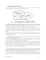
engineering tasks”. In this section the definition of Engineering Automation is related to
Software Engineering and (Professional) End-User Development. Finally, the definition is
clarified with examples.
2.1
Software Engineering
The IEEE Computer Society defines Software Engineering as “the application of a systematic,
disciplined, quantifiable approach to the design, development, operation, and maintenance
of software, and the study of these approaches; that is the application of engineering to
software” [15]. Similar approaches might suit engineering automation developers as well,
and are certainly worth studying.
Regular engineers who develop software are not software engineers but end-user
developers and professional end-user developers in particular. One can expect that a regular
engineer will encounter different problems than a software engineer will: where the regular
engineer lacks the skills to develop quality software efficiently, the software engineer lacks
an understanding of the application domain. Different problems most likely require different
solutions. Therefore the scope of this work was limited to regular engineers, and
Engineering Automation was defined accordingly.
2.2
End-User Development
In [16] End-User Development is formally defined as:
“A set of methods, techniques, and tools that allow users of software systems, who
are acting as non-professional software developers, at some point to create, modify,
or extend a software artifact.”
Examples of End-User Development are spreadsheets, recording macros in word processors,
customized email filtering and processing rules, but also scripting interfaces embedded in
applications with a low entry-level.
A major driver for End-User Development is the diverse and changing nature of
requirements. It is hard for external software professionals to keep up with their users’
needs. This is avoided if the users themselves are able to continuously adapt the systems to
their needs. [16]
Part I: Thesis article
3
2.3
Professional End-User Development
Some end-user developers develop software in pursuit of their professional goals, in areas
outside computer science such as engineering, medicine, business and more. Some of the
tasks they need to perform are suitable for automation, yet they might be so specific that a
commercial solution is not readily available. [16]
These professionals tend to have a highly technical field of expertise, in which case they are
used to formal languages and abstraction and hence tend to have few problems with coding
per se, which sets them apart from regular end-user developers. [5]
The following definition for professional end-user developers is based on a description given
in [5], and is similar to the definition given in [16], except for the constraint on technical
professions:
Professional end-user developers are people working in highly technical
knowledge-rich professions, who develop their own software in order to advance
their own professional goals. While they are very sophisticated in their field of
expertise, they have received little Software Engineering education or training.
Engineering curricula nowadays commonly include one or more courses on particular
programming languages. Useful as these courses are, they rarely treat Software Engineering
in-dept due to time constraints. The definition of professional end-user developers given
above therefore still applies to engineers who followed these courses.
2.4
Examples
Examples of Engineering Automation are a production cost spreadsheet, a heat transfer
simulation model in a graphical modeling environment like Simulink or Labview, pre- and
post-processing scripts for an aerodynamic analysis, an experimental finite-element method
implemented in a high-performance language such as Fortran, and a script to automatically
draw a common part feature within CAD software.
Examples of software that are not included in the definition are top-of-the-market
simulation packages, CAD software and PLM solutions, because that software is typically
implemented by or with extensive support from software engineers, rather than regular
engineers.
Part I: Thesis article
4
3
Engineering automation practice
An initial study was performed to understand the needs and culture of engineering
automation developers. From literature, a general view on Engineering Automation was
developed. Subsequently interviews with experts were held to validate the findings from
literature and to gain deeper understanding through practical examples and additional
explanation. The results from the literature review and the interviews are presented sideby-side in this chapter.
3.1
Focus questions
The initial study was set out to answer the following questions:
How is engineering automation software currently developed?
Why is engineering automation software developed the way it is?
How is engineering automation software currently shared and reused?
What would more reuse of engineering automation software require?
The answers to these questions provide the required understanding of both the needs and
culture of Engineering Automation developers, in particular in relation to reuse.
3.2
Interview participants
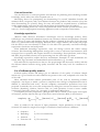
In total six interviews were held with engineering automation developers in industry and
academia. All participants devoted a large part of their time to writing software. Except the
oldest participant, all had followed basic programming courses in university. All of them
were self-educated in particular programming language(s) while on the job.
Four participants were recruited in an engineering company (Airbus Group Innovations).
They represent a wide spread in work experience, from a couple of months to more than
ten years with a median of 1.38 years, and used Engineering Automation for various tasks:
automating conceptual design and simulation workflows, post-processing simulation data
for visualization, developing knowledge-based engineering applications and data-mining
knowledge rules.
Two participants were graduating engineering students (faculty of Aerospace Engineering,
Flight Power and Propulsion chair, TU Delft), selected because of their experience with a
project involving the reuse of and collaboration on an application for conceptual aircraft
design.
Part I: Thesis article
5
The interviews results will not be valid for the entire engineering automation community:
this would require a far larger amount of interviews than can be conducted within the scope
of this project. At most, these interview results will confirm or nuance general findings from
literature.
3.3
Interview method
The interviews were semi-structured. The same topics were discussed with each participant
by using 22 fixed questions, sent in advance. Follow-up questions allowed the interviewer to
go into detail and understand each of the answers better. The interviews took about 1:30
hour each and were recorded with the participants’ permission.
The interviews were processed in two steps. In the first step, the recording was transcribed
and slightly summarized. The summary was reviewed by the participant to correct any
misunderstandings and filter out confidential information. In the second step, the answers
of all participants were aggregated and compared per question. Where applicable, the most
prominent answer was distilled by counting how many of the participants referred to that
answer and by taking into account the importance indicated by the participants. This was
published in [17].
3.4
Results of literature review and interviews
The findings from literature and interviews are presented side-by-side, per focus question.
3.4.1
How engineering automation software is currently developed
Literature
Based on experiences of her own and of colleagues, [18] states that the average (academic)
engineering automation researcher is far removed from the software engineering world.
Common development practices from Software Engineering are not adopted: requirements
are not explicit, software design is done minimally, testing is done ad-hoc, documentation
often skipped and the traceability between the engineering knowledge and the application
code is missing [1], [5], [9].
Between plan-based (traditional) development methods and agile development methods,
engineering automation developers choose the latter, but they adopt them only selectively:
communication and flexibility are embraced – they work highly iteratively, incrementally
and interactively – but in the areas of requirements and testing, agile practices are not
adopted. [5], [19].
The software development practices that are used are error-prone. For example, it is
common to passively look for incorrect behavior rather than actively gathering evidence of
correct behavior [5].
Part I: Thesis article
6
Interviews
These findings from literature were confirmed by the interviews: the participants were not
aware of software engineering practices, or they hardly used them correctly.
The requirements are implicit from project goals.
The design is not planned to a high degree. One participant said: “There is no prior plan for
the code. I just start doing it and see what happens, see what falls out.” At most, some
thought is given to the top-level data flow: what goes in, what must come out, and vaguely
the steps to make that happen.
The software is tested while it is developed by running the complete program and manually
verifying the output. There is a prior expectation for the output, but not a crisp value.
Automatic testing is not used. Testing parts of the code individually is only done during
debugging. Multiple test cases are used, but there is no explicit test plan of what has to be
tested.
During the interviews, participants mentioned problems which could have been avoided
with more testing: one participant mentioned that after making a particular change, he was
fixing bug after bug for one week, until finally the program ran again. Another participant
told that only after weeks of reverse-engineering he could find out that the code of his
predecessor was not entirely correct.
Documentation is limited to source code comments written informally for the author
himself. Traceability is limited to mentioning the origin of equations.
The development method found is highly iterative and interactive. There is no explicit
process however, and in practice the development process is better labeled as “ad-hoc”
than agile.
3.4.2
Why engineering automation software is developed the way it is
Literature
The prime explanation given in literature for the ad-hoc development is tension between
research goals and software engineering goals: attention tends to shift to the first. The
software is in the first place considered as a research tool to address immediate research
needs, i.e. short-term goals. [6][20][21]
The underlying problem is an incentive problem: academics are rewarded for publications
which lead to funding, engineers in industry for the output of their software; for both, the
software work itself is normally not rewarded. [6] [20]
Furthermore, literature offers explanations for several aspects of engineering automation
development.
Part I: Thesis article
7
The exploratory nature of research and design makes requirements elicitation difficult. It is
argued that because an engineering automation developer is both the developer and the
domain expert, this is partially compensated for. [19]
The available methodologies for designing and modeling engineering automation software,
such as CommonKADS [22] and MOKA [23], are perceived as too difficult and complex,
especially for small teams [24]–[27].
Several explanations were found to explain the lack of systematic testing. Since the
developer is also the user, using the system is considered testing too. Other contributing
factors mentioned are having to test both theory and implementation at the same time [5],
[19] and the lack of formal requirements [19].
Agile software development methods fit well with scientific software development because
they share an emphasis on responsiveness to change, on collaboration and on an iterative
nature [5], [19].
Interestingly, J. Howison and J. Herbsleb [6] note that the software engineering community
proposes the scientific software community to adopt techniques, but without encouraging
that community to understand what is the cause of the problem these techniques are trying
to fix. This might explain the limited adoption of software engineering techniques.
Interviews
The interviews show the tension described in literature: all software work except the coding
itself has to compete with more urgent work. One participant said: “I would like to describe
the engineering knowledge, […], but generally, there is no time. The codes that are written
are just there to do the job, get a value out.”
Clients and supervisors ask for engineering solutions and answers, not software. The
software and along with it software engineering practices receive the minimal amount of
attention, and enthusiasm for devoting more resources is generally low.
Best-practices are not picked up due to a lack of training. One participant said: “We
wouldn’t even talk about that. It’s almost assumed in the team that people can program.”
In line with the main explanation found in literature, only few consider it feasible to write
detailed requirements in advance.
Only one participant was aware of design methodologies like MOKA, which he said was
perceived by his team as “a fairly theoretical overhead”. One participant explained why he
did not make a detailed design of his software: “I found it difficult to write down beforehand
what I’m about to do. It was never taught how to do that for programming, while we did
learn how to do this for say mechanics.”
The participants have the feeling that they can get by with on-the-go testing as they develop
and use their software. They think systematic testing takes too much time or will not pay
Part I: Thesis article
8
off. Separating theory and implementation errors or the lack of formal requirements was
not felt to be an issue by the interviewed participants.
One participant illustrated what happened as a result of a lack of testing: “When I received
the tool, my supervisors assumed that it worked, and that I could simply extend it.” The
supervisor, after finding out that was not the case: “Oh well, then I must have read a very
good report…”
Some feel that external documentation will not be read. Instead, people ask questions
directly, which saves time.
Going through the calculation process step by step and seeing the output leads to new
insights and triggers iteration. This responsiveness to change and built-in iteration matches
with agile development methods.
One participant explained why he did not use a formal method: he admitted that, even
though he in general acknowledged the value of formal methodologies, he could not get
himself to look out for those and use them for his software work.
3.4.3
How engineering automation software is currently shared and reused
Literature
Segal [4] and J. Howison and J. Herbsleb [6] report a limited level of sharing and
collaboration, among professional end-user developers and in the scientific software
community respectively. Software is passed on from researcher to researcher, resulting in
problematic software artifacts.
Interviews
Among the interviewed participants, reuse takes place on a small scale, within teams.
Knowing about existing code is done through internal team interaction – there is no central
repository. Reuse occurs by copying legacy code and modifying it. The ideas behind the
software are shared informally, if one asks for it, rather than writing them down. One
participant said: “We save a lot of time by speaking to each other rather than writing things
down. The problem of documentation I found is that no one reads it, people rather look
over their desk and ask directly.”
Currently, code is copied rather than turned into a shared library, because that easily gets
broken or is moved. One participant said: “Their change might work for their input, but it
can break yours. When things like that happen, you quickly loose interest in pulling changes
from others.”
3.4.4
What more reuse of engineering automation would require
Literature
Activities related to software quality and software reuse are under-resourced because
research goals prevail over software goals. These activities include documenting,
Part I: Thesis article
9
distributing and supporting software, and following software engineering training.
Distributing and supporting research software is in fact a very time-consuming activity. [4]–
[6]
Reuse is further impeded by the instability of the communities of practice. Software
developers are at the bottom of the research ladder, and career moves such as graduation
or promotion cause a high turnaround and associated knowledge loss. [4]
Interviews
The competition for resources between working on current research and preparing for
reuse in future research was clearly present in the interviews. Getting the software to work
prevails, there is little to no incentive to prepare for later reuse. Even though sharing and
collaboration might be overall beneficial to the organization, it introduces overhead which
comes at the expense of the one that must facilitate reuse. One participant said: “I now
have already plenty of work, so I will not spend more time on making things pretty. But I
think that if they had insisted on me taking care of the code, rather than giving me more
work, my work would have been more valuable for the following students.“
Among the interviewed participants, team members who leave was not felt as an issue that
had affected them.
Each of the participants was asked about what they would desire when reusing code.
Requirements are not expected. All participants mentioned the need for high-level
documentation: a clear structure (i.e. the software components) and understandable
“steps”, also referred to as “engineering process”, “story”, “storyboard” or “flow”. Several
participants stressed the need to see how the high-level documentation maps to the code.
In the source code, comments are always expected. Some attribute high value to
performance and conciseness, while others (in particular novices) insist on simple to
understand and easy to read code: “Code from more experienced team members can be so
compact it becomes difficult to understand.”
The practical experience of the two academic participants, who had to extend existing
software, showed two reuse traps: it was difficult to understand the code because of its low
quality and poor and sometimes inaccurate documentation, and there were hidden
assumptions and flaws under the hood.
3.5
Discussion
The results from both literature and interviews are discussed per focus question.
3.5.1
How is engineering automation software currently developed?
Overall, the software is developed iteratively and incrementally, without a formal method.
Requirements elicitation, software design, testing and documenting are largely skipped.
Part I: Thesis article
10
Rather than thinking their software solution through first, engineering automation
developers quickly start coding and keep tweaking the code until the overall application
output fits with their expectation. For any software system of realistic size, this is not the
fastest way to develop software, nor can the software be expected to work correctly for
inputs other than the ones manually checked [28]. In fact, giving sufficient thought to a
problem before embarking on a solution, and spending sufficient resources on systematic
validation, are two general guidelines applicable to any engineering discipline.
The lack of systematic testing is particularly problematic: the code is fragile when
introducing changes or even downright incorrect.
3.5.2
Why is engineering automation software developed the way it is?
Underlying engineering automation development is the need to provide answers, not
software. Any activity that is not part of getting the answer is perceived as time-consuming.
It was found that this applies to software design, documenting, testing systematically,
integrating with existing software and supporting reusing developers, but also to software
engineering training.
3.5.3
How is engineering automation software currently shared and reused?
The overall level of sharing and reuse reported by the participants matches the limited level
described in literature. Small sharing networks do exist, informally within teams. These
networks are used to share pieces of legacy code and explain them upon request, not for
close collaboration. Being asked for explanation is preferred over writing documentation as
it saves time.
These networks show the large importance of the social aspect in reuse: both discovering
existing software and reusing software are now closely linked to internal team interaction.
3.5.4
What would more reuse of engineering automation software require?
There is a discrepancy between what is currently done by engineering automation
developers and what they desire when they have to reuse code. This discrepancy is formed
along two lines: understandability and validity. The discrepancy is shown in Table 1. Low
code quality and poor documentation make software hard to understand. The validity on
the other hand is undermined by the lack of systematic testing, which makes it hard to
guarantee the correctness of the code, and the consistency of the documentation with the
code. What is needed on the other hand is simple to understand code with adequate
comments, the steps and structure in the code clear and documented, tests to ensure the
correctness of the code and finally documentation that matches the code.
Part I: Thesis article
11
Table 1: Difference between what is currently done by engineering automation developers
and what is needed when they have to reuse code.
Topic
Understandability
Currently done
Low code quality, but usually with comments
No external documentation other than
reports
Desired
Simple, clear code with comments
High-level documentation about the
structure and the steps
Validity
No systematic testing
Documentation not entirely consistent with
code
Verifiable correctness of code
Documentation consistent with code
3.6
Conclusions
Literature and interviews show that the level of reuse in Engineering Automation is limited.
Sharing and reusing software is done informally within teams. The two most pressing issues
that impede reuse are understandability and validity. When these issues are resolved,
raising the level of reuse further will require scaling up the internal team interaction on
which reuse now relies. Also, sharing with others and supporting them will need to become
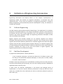
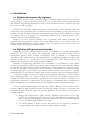
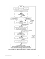
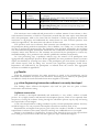
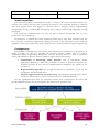
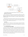
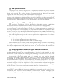
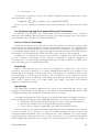
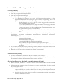
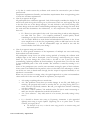
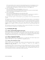
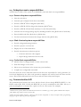
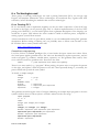
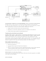
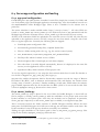
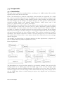
easier and/or more rewarding. These issues are shown schematically in Figure 1.
Figure 1: Schematic representation of obstacles that impede reuse in Engineering Automation
Understandability The understandability of the code is low due to the lack of high-level
documentation and due to unclear code. High-level documentation is desired to help
understand the structure of the code and the process steps.
Validity The validity of the code is undermined by the absence of systematic testing.
Discrepancies between the documentation or reports and the actual software further
reduce the trustworthiness.
In addition to identifying technological issues, the literature and interviews also revealed
important non-technological obstacles in the current engineering automation culture that
must be accounted for when introducing change. Four such obstacles were found.
Skipping laborious tasks where possible Software activities other than software
construction itself are perceived as time-consuming and not a necessity. This applies to
Part I: Thesis article
12
activities like designing, documenting, testing, integrating and supporting software, and
software engineering training.
Only incentive for answers Engineering automation developers are not rewarded for those
non-construction activities. They do these activities only as far as they can justify these
activities because it helps them to get an answer to the engineering problem they are trying
to solve. Effort to make their software more reusable comes at their own expense.
Limited Software Engineering experience Engineering automation developers have limited
experience with Software Engineering and the basic practices used by software engineers.
They are unaware of how software engineering practices like designing and testing or even
basic tools can fix the problems they are experiencing.
Iterative and incremental development Engineering automation software is developed
iteratively, incrementally and interactively. It is common for a project to start vague,
without many requirements and without much of a design. Developing the calculation
process or seeing output triggers new insights and revisions of the entire software solution.
These conclusions show that to promote reuse, several issues must be resolved. GenDL
Designer, which will be described next, was developed to tackle the first few, and to further
refine and solidify the understanding of engineering automation development.
Part I: Thesis article
13
Part I: Thesis article
14
4
GenDL Designer
4.1
Scope
GenDL Designer is a graphical design tool with code synchronization for GenDL, an
open-source object-oriented knowledge-based engineering system. GenDL developers can
create software design diagrams and generate code skeletons from them. Afterwards, both
the diagrams and code can be changed independently. GenDL Designer continuously
analyses both and lists inconsistencies between the two. Optionally it helps to resolve
inconsistencies in both directions, by generating additional code skeletons or diagram
elements. This will be referred to as incremental code and design documentation
generation.
GenDL Designer’s overall aim is to improve understandability and validity, in order to
contribute to more reuse. GenDL Designer aims to improve understandability by
encouraging developers to create design documentation, and to create this documentation
for a large part before actually writing code. This encourages a well-thought and sensible
application structure, just like thinking through the problem and possible solution
alternatives is beneficial in any engineering discipline. GenDL Designer aims to improve the
validity too, by checking that the design documentation is complete and still corresponds to
the code.
In summary, GenDL Designer tries to accomplish what is now hardly done among
engineering automation developers: that applications are documented properly and that
developers create a design before writing the corresponding code.
To accomplish this, GenDL Designer takes into account the four non-technological obstacles
related to the culture of engineering automation developers identified before. By
generating code skeletons from the design and diagram elements from the code, designing
becomes a directly value-adding activity and documenting becomes less time consuming.
GenDL Designer does not require much training apart from reading a short manual or
watching screencasts. And finally, GenDL Designer is designed from the ground up for
iterative development, by generating code and design documentation incrementally.
GenDL Designer was developed for Engineering Automation developers and therefore
differs from existing general software engineering tools with similar objectives, such as the
IBM Rational Software Architect products [29], Sparx systems’ Enterprise Architect [30] and
ArgoUML [31]. Most importantly, it uses a simple modeling language tailored to GenDL,
rather than a full-featured modeling language suitable for general software development.
Part I: Thesis article
15
The lack of options to choose from makes the tool easier to pick up. GenDL Designer does
not support automatic synchronization as well as the commercial solutions from IBM and
Sparx Systems, but on the other hand does provide more control over synchronization than
those solutions do.
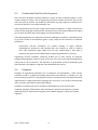
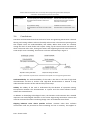
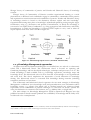
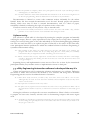
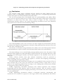
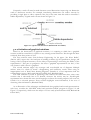
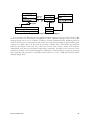
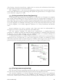
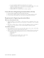
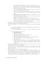
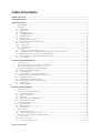
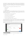
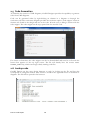
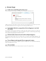
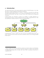
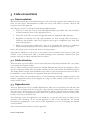
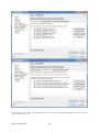
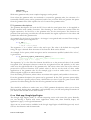
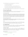
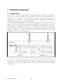
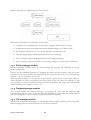
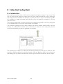
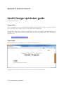
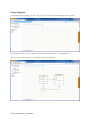
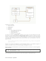
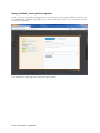
Figure 2: Web-based User Interface of GenDL Designer
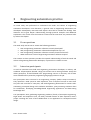
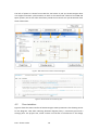
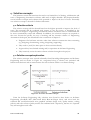
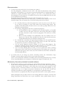
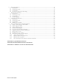
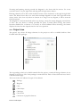
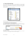
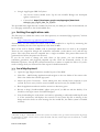
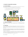
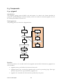
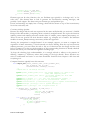
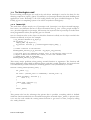
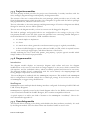
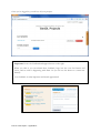
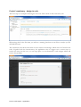
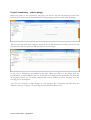
Figure 3: Screenshot of the consistency pane
4.2
User interface
Figure 2 shows the main interface of GenDL Designer. Most prominent is the drawing canvas
for the diagrams. Tabs allow switching between diagram panes, a consistency pane and a
settings pane. The project tree, which contains an overview of all elements in the design
Part I: Thesis article
16
diagrams, remains visible at all times. Furthermore, there is a help center and a feedback
button.
On the drawing canvas diagrams can be created. One project can contain multiple diagrams,
to deal with the complexity of large projects. Multiple diagrams can contain the same
element, so that one diagram can define elements and other diagrams can reference them.
Shortcut elements can be added to a diagram to quickly navigate between diagrams.
The consistency pane, shown in Figure 3, lists all inconsistencies with references to where
the inconsistency was found. Most consistency checks verify whether for each element in
the design and the code, a corresponding element with the same name can be found in the
code and the design respectively. As a result, inconsistencies are typically reported as a
missing element.
The user has full control over the resolution of inconsistencies – they are not resolved
automatically. This ensures that the design tool will not block the workflow of the user, even
when some notifications would be incorrect or irrelevant for any reason. This makes the tool
more robust towards the future. It also assures to new and suspicious users that their design
and more importantly their code is safe, building trust.
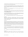
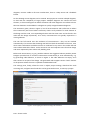
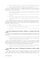
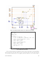
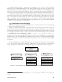
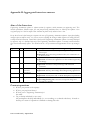
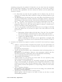
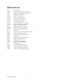
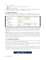
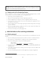
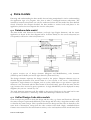
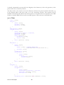
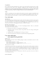
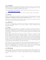
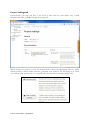
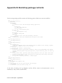
Below each inconsistency, in grey, possible solutions are suggested. Where possible, GenDL
Designer provides links to resolve inconsistencies automatically or semi-automatically, e.g.
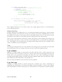
by generating code skeletons, as shown in Figure 4. The code skeletons are empty, since
their content is not part of the design. The generated code snippets contain “todo” markers
at the position where the user is expected to add detailed code.
The settings pane, finally, allows the user to adjust project settings, download the code
mirroring tool, and generate all code that can be generated at once, to start up a project.
Figure 4: Code snippet generated from design documentation
Part I: Thesis article
17
4.3
Graphical notation for diagrams
The graphical notation is based on the class diagram notation of the Unified Modeling
Language (UML) [32], but was simplified to be more accessible for Engineering Automation
developers, and it was adjusted to fit better with KBE languages such as GenDL. The
notation emerged among GenDL developers at the TU Delft as a practical variation on UML
and has recently been defined in [33].
GenDL classes do not have attributes but have input slots, computed slots and child slots
instead. Input slots and computed slots are shown in the diagrams where attributes would
be expected. Child slots are visualized as a rectangle outside the class block, connected to
the class with a composition link. This emphasizes the tree structure of the model and
provides space to display the input slot values (or rules) the child might have.
Furthermore the notation uses the generalization/specialization connector for both mixin
relations (super classes) and child type relations.
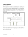
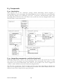
4.4
Application architecture
GenDL Designer is built as a web-based application. Users draw diagrams and compare
these to their code inside the web-based application, while they still write code locally on
their own system, like they used to do. This setup requires no changes to the existing
workspace of engineers and therefore keeps the barrier to get started with GenDL Designer
low.
The link between the web-based system and the local system is provided by a small utility
that runs locally and mirrors the code to the web-based system. This allows the web-based
system to know the current state of the code.
The design that is represented visually in diagrams is internally also stored as a traversable
graph with nodes and edges. This graph, the design model, and the parsed contents of the
code, the code model, are both transformed to a similar data structure. An algorithm
compares these and generates a list of inconsistencies.
Nearly every action of the user invokes a request to the server. All requests are logged, and
can be analyzed to derive usage statistics. Because GenDL Designer is offered as an on-line
service, this can be done continuously to monitor usage and react to issues as soon as they
appear, long before the end of the research.
4.5
Alternative GenDL Designer usage patterns
While intended as a design tool, GenDL Designer can also be used as a learning and tool as a
reverse-engineering tool.
Novice GenDL programmers can draw designs, which is relatively easy to pick up, and learn
how it maps to code, by requesting a code snippet for an element in the design. Also, the
Part I: Thesis article
18
consistency check helps them to spot where the software is different from what they
intended.
GenDL Designer can be used to reverse-engineer existing code, by comparing the code to
empty diagrams. GenDL Designer will propose to resolve missing design documentation by
importing it from the code. All the user has to do is drag elements from the project tree into
diagrams.
Part I: Thesis article
19
Part I: Thesis article
20
5
Validation experiments
5.1
Introduction
GenDL Designer needs to be deployed to GenDL developers to verify and validate it as a
solution. On the level of verification, the question is whether the solution is working as it
should: does incremental code and design documentation generation, as implemented in
GenDL Designer, encourage engineers (1) to document applications correctly and
completely, and (2) to create a design before writing the corresponding code? Metrics will
be proposed to address this quantitatively.
On the level of validation, it must be determined whether incremental code and design
documentation generation is an appropriate solution to the problem it is supposed to
tackle: does it promote sharing and reuse, by improving understandability and validity? As
there is little doubt on the positive effects of understandability and validity on reuse, the
current work will focus on whether understandability and validity were actually improved.
For this, user feedback will be gathered.
5.2
Academic experiment
A first large-scale experiment will be held in the context of a graduate course at the TU Delft
on Knowledge Based Engineering (KBE). As part of the course, about 50 students learn to
program in GenDL. The final assignment is to develop a KBE application using GenDL in
teams of two. The system and its documentation have to be defended during a review
session.
This course has been held for several years, and the general experience of the tutors is that
students struggle to pick up GenDL programming, that they structure their code poorly, and
that they do not create a design beforehand even though they were advised to do so.
Instead, they draw diagrams as documentation shortly before the review session, since it is
a required deliverable. They do not fully embrace the diagrams as a design tool.
The boundary conditions of the course are similar to general engineering automation
boundary conditions: a stringent deadline and limited experience with the software
language and software development in general. What is different however is the up-front
requirement for documentation. The experiment will therefore not establish whether
GenDL Designer triggers the creation of documentation. Instead, it will only establish
whether it increases the documentation quality and quantity. The most trustworthy
Part I: Thesis article
21
validation method remains deployment in industry with realistic use cases. Such an
experiment would be the next step.
5.3
Metrics
For the verification of GenDL Designer, two metrics were developed. They are based on the
inconsistency between the design and the code. The first is the overall consistency at the
end of the project and is an indicator for correct and complete documentation. The second
is the flow and indicates whether the design was made before the code was written. This
metric is derived from measuring changes in inconsistency and the user activity that caused
the change.
5.3.1
Measuring inconsistency
Each inconsistency notification is assigned a weight, depending on the gravity of the
inconsistency. The weight includes the weight of sub-inconsistencies, such as missing
attributes when the whole class is missing in the first place. Weights for each type of
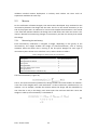
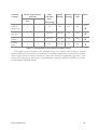
inconsistency were chosen on a scale from 1 to 5, and are shown in Table 2.
Table 2: Weights for different kinds of inconsistencies
Inconsistency
Missing class
Missing function or method
Missing child
Missing attribute
Missing or different type of child
Missing superclass
Different attribute kind (i.e. settable or not)
Weight
3 + sub-inconsistencies
5
5
3
2
1
The total inconsistency is given by:
5.1
That is, the total inconsistency between the design model D and code model C at moment i
is the sum of the weights W for each notification n in the inconsistency notification list L at
moment i. As an example, consider the situation where the design and the code differ by
one class that is only in the design, with three input slots and two child slots. Given the
weights in Table 2, the inconsistency is calculated as:
5.2
Part I: Thesis article
22
5.3.2
Measuring completeness and correctness of documentation
The degree to which GenDL design accomplishes the first objective, complete and correct
documentation, will be measured by calculating the consistency between the design and the
code at the end of each project, relative to what it could have been:
5.3
In this equation, subscript end refers to the state of the models at the end of the project,
while subscript 0 refers to the state at the start of the project, i.e. when the model was
empty. The consistency will be a number between 0 and 1. 0 means there is a complete lack
of correct design documentation, while 1 indicates that the design documentation
corresponds to the code perfectly.
5.3.3
Measuring the level of design-before-code
The second objective, whether users design before writing code, is measured by calculating
to which degree information flows from the design to the code and from the code to the
design. The modifications are grouped into sessions of successive design or code
modifications. At the end of each design session and each code session, the inconsistency
change during that session is calculated:
5.4
Here, s refers to the session for which the change is calculated.
The flow of information is positive if information flows from the design to the code. This is
the case when the inconsistency increases during a design session or decreases during a
code session. The design is then leading with new information; the code catches up with
information that was already in the design. The set S+ of sessions with positive flow and the
set S- with sessions of negative flow are defined as:
5.5
In these equations, SD and SC are the sets of design and code sessions respectively. Summing
the flows in each set yields the total positive and total negative flow:
5.6
Finally, the overall flow indicator is calculated, as a number between -1 and 1:
5.7
A flow of 1 would indicate that the design always perfectly foresaw what had to be
implemented, while a flow of -1 would indicate that the design was only created to
Part I: Thesis article
23
document existing code. A higher flow indicator would generally be better, but a perfect
score of 1 is unrealistic in real-life projects and by no means required.
Part I: Thesis article
24
6
Experiment trial runs
6.1
Introduction
Individual testers were given access to GenDL Designer, in preparation of the full-scale
experiment that will be conducted in spring 2014. These trial runs uncovered bugs, triggered
new feature requests and allowed refining the support material. It also gave the opportunity
to develop and test the log processing facility with realistic user input.
Some testers used GenDL Designer to set up their project from the beginning. Others used it
to document already existing code, written by themselves and/or others. A final group used
GenDL Designer to perform a small assignment (“toy project”), purely for the sake of testing
GenDL Designer. In total, 7 users participated in testing.
The remainder of this section will present the data that was extracted from the server logs,
the calculated metrics, and the user feedback that was gathered. Although the amount of
users in the trial runs is too small to draw solid conclusions, the data will be processed, the
results will be discussed and preliminary conclusions will be presented, as an example of
how it will be done when the full experiment will be conducted.
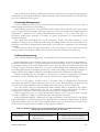
6.2
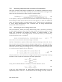
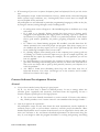
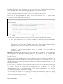
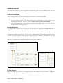
Server log data
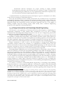
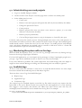
The server log data provides a timeline of user activity and inconsistency events. An example
of such a timeline is visualized in Figure 5. One can clearly see how the participant switched
back-and-forth from the design environment (dark grey) to the code environment (lighter
grey) and how he resolved inconsistencies in both directions. Also clearly visible is how the
inconsistency sometimes goes down during code sessions (positive flow), and sometimes
goes up (negative flow).
6.3
Metrics
The two metrics, consistency at the end of the project and the average flow during the
project, are calculated from the timelines for each project. For the 7 trial runs, the results
are plotted in Figure 6. In the plot it can be seen that users who started from scratch, for the
toy project or for a regular project, obtained a high consistency, and all but one also a
positive flow direction. The users that used GenDL Designer as a documentation tool, turn
out to have a high variation in consistency, and (obviously) have a very negative flow
direction.
Part I: Thesis article
25
Figure 5: Example timeline of user activity during a trial run (user 2).
Figure 6: Consistency and flow for each user in the trial runs.
The project of user 7 was not finished at the time of writing.
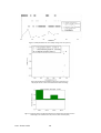
Figure 7: Evolution of the average flow direction throughout the project of user 2.
Total design and code sessions: 23 (5 or 6 in each of the 4 parts)
Part I: Thesis article
26
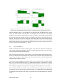
Figure 8: Evolution of the average flow direction for 4 of the 7 trial runs (clockwise: user 1, 3, 4 and 7). The
project of user 7 was not finished at the time of writing. Total design and code sessions: 81, 42, 13 and 31.
The flow discussed so far is an average for an entire project, yet different parts of the
project can have different flow directions. To investigate this, the sequence of alternating
design and code sessions of each project is split in 4 parts of equal length and the flow is
calculated for each part. Figure 7 shows the evolution of the flow for the same trial run as
Figure 5. The project starts with a large flow from the design to the code. Afterwards, the
average flow becomes close to zero, indicating that about the same amount of information
flows in both directions. Figure 8 shows the flow evolution of the other projects, except for
the ones with purely negative flows, i.e. flow -1.
6.4
User feedback
Besides measuring user activity through log files, users were also asked for their opinions
and remarks about GenDL Designer. Due to the limited number of users so far the results
here are mostly based on individual quotes.
The most often heard remark is “I wish I had this tool available when I started with GenDL”.
Some users indicate that it stimulates them to work more structured, that it provides them
with a clear overview of their project, and that they found the overview helpful when
explaining their software to others.
Several users feel that applications become more consistent and orderly. One user predicts
that, if the concept would be used in an engineering company, it would have a chaosreducing effect on the continued development of existing software. Another user reported
that making the design documentation for existing code revealed deficiencies in the code.
The users who started from scratch usually do not mention that using the tool saves them
time, but they do not mention that it costs time either. It is noted however that fiddling with
the diagram layout and lines takes time, and that the tool is missing features to make this
easier.
Part I: Thesis article
27
Those who used it as a documenting tool for existing code, found it to be a fast and accurate
documentation tool, faster and more accurate than alternative ways of documenting.
Nearly all users expressed their appreciation for the modern interface. One user noted that
he could even introduce the tool and diagrams to those who did not know GenDL.
Some users ran into bugs which made them loose time. Most users also found missing
features that in their opinion would have been valuable and time-saving, like integration
with the GenDL compiler and full-automatic diagram creation.
6.5
Risk of reflexivity
The outcome of the research might be distorted due to reflexivity. Reflexivity refers to the
possibility that a participant responds and behaves according to a perception of what he
thinks the researcher expects. For example, spending more time explaining the intended
usage of GenDL Designer increases the risk of finding an artificially high conformance to that
intended usage. In other words, there is a risk that the findings of this research are not valid
for realistic engineering environments, because there the particular experiment coordinator
and his guidance are not present. Therefore, the interaction between the users and the
coordinator is described here.
The get users started, they were introduced to the user interface with a small
demonstration. This is also when they were informed that manuals and screencasts were
available and that usage statistics were gathered. They were also encouraged to contact the
experiment coordinator when they encountered issues.
Only a few users contacted the researchers, mainly for reporting a bug that blocked them.
Most users preferred to get along themselves. In a few instances, the coordinator visited or
contacted the participants to check up. Sometimes users had indeed questions, and opened
the GenDL Designer application to discuss. In those instances, it was sometimes possible to
give the user extra tips regarding less obvious features of GenDL Designer, such as the
possibility to create several interlinked diagrams.
Overall, the researchers tried to remain neutral and stressed that participants had to use the
software the way they found it most useful – even if that meant not using it at all.
Part I: Thesis article
28
7
Discussion
In anticipation of the results of the actual experiment, the results of the trial runs are
already discussed to arrive at preliminary conclusions.
7.1
Consistency metric
The users who started from scratch share the same tendency for high consistency. This is
encouraging, since this implies the creation of design documentation. Without GenDL
Designer, this is usually not created.
The driving force behind this tendency is most likely the consistency list: all users watched
the consistency pane regularly. The users apparently felt the need to eliminate the
notifications in the list. One reason might be that the notifications are presented as errors:
something is wrong and needs to be fixed. As long as the errors are there, the solution is not
ready and the problem is not solved. Another reason might be that, at least initially, the
users adhered to the usage pattern they had seen in the short demonstration and/or the
quickstart manual. This pattern focuses on resolving inconsistencies that emerge.
Two of the three users who documented existing code documented a very large portion of
their code; one only documented a small portion. Interestingly, the 3 users who used GenDL
Designer to create documentation did not create more documentation that the 4 users who
did not use GenDL Designer for the sake of creating documentation.
7.2
Flow metric
Users who started from scratch design more in the beginning than in the end: the flow tends
to decline. This is what you would expect: once users are in the code, small problems are
easier fixed there.
It is interesting to note that different users working on the same toy project share the
declining flow evolution pattern but still differ significantly in average flow (users 1 and 2
versus user 3, flow +0.54, +0.65 and -0.27 respectively). To some degree, these numbers
quantify the personal preference for working top-down or bottom-up, i.e. structure
rigorously first or let the structure evolve out of working software. This personal preference
has a notable effect on how GenDL Designer is used, and maybe even on whether or not it is
used. The user with negative flow (user 3) might have stopped using GenDL Designer in a
real project, since he was rather creating documentation than designing. Under the pressure
of a deadline, that documentation activity would probably have been dropped.
Part I: Thesis article
29
When used as a documentation tool, the flow is naturally highly negative. One user
indicated that he found deficiencies in his code while documenting. The flow evolution for
this trial run, lower right in Figure 8, confirms this. After some documenting activity, visible
as highly negative flow, the user fixed the issues at the design level, and pushed these
changes to the code, visible as positive flow in part 3 of the project.
7.3
User feedback
In summary, the feedback of the users is that using GenDL Designer reduces chaos, adds
structure and provides overview, in the development process and in the application itself.
This directly and positively affects the understandability. Users also appreciated the ease
with which valid documentation could be created.
The deficiencies one user found while documenting illustrates that understandability and
validity are related: increasing the understandability uncovers mistakes that threaten the
validity.
For people who start from scratch, GenDL Designer was not perceived as a time-saver, but
not as a burden either. In other words, the tool gave them the documentation more or less
for free. That is already an encouraging result. Still, users who do not see the point of
documenting have no incentive to use the tool. For them, further time-savings must be
pursued, e.g. with better layout mechanisms.
The users did not need a background in Software Engineering to work with GenDL Designer.
This was, as intended, one barrier less when convincing test users, and will be equally
beneficial in real-life engineering environments.
The users who started from scratch worked indeed iteratively, revising along the way, and
GenDL Designer was suited for that approach. Timelines show that they kept switching
between the design environment and code environment. The flow evolution plots reveal
that information flowed in both directions throughout the entire project. Users kept using
GenDL Designer during these iterations.
Part I: Thesis article
30
8
Conclusions
8.1
Initial study
Understandability and validity are currently the most important issues that impede the
reuse of Engineering Automaton. Later on, more reuse will also require scaling up the
internal team interaction on which reuse now relies, and supporting others has to become
more rewarding.
The success of solutions to these issues largely depends on how well these solutions take
into account several non-technological obstacles related to the current engineering
automation culture. There is only an incentive for the answers that will be obtained with the
software. Laborious tasks that do not contribute directly to these answers, such as designing
and testing, are skipped where possible. Software engineering experience is limited and
finally, the development is highly iterative and incremental.
8.2
Deployment results
Based on this knowledge, GenDL Designer was developed, founded on the principle of
incremental code and design documentation generation. GenDL Designer’s aim is to
encourage users to create accurate design documentation, and even create this
documentation before writing the corresponding code. A full-scale experiment with GenDL
Designer will be conducted in spring 2014; in anticipation of that, trial runs were held. The
data from these trial runs are used in this report for drawing the following preliminary
conclusions.
GenDL Designer encourages the creation of accurate design documentation and encourages
designing before implementing. This conclusion is based on the observation that when
GenDL Designer was used for newly started projects, nearly complete documentation was
created and a large part was created before writing the corresponding code. In regular
Engineering Automation projects, that would have been unlikely. It is however the case that
not all users found it necessary to document all code and that some users have a lower
tendency to design-before-code than others – GenDL Designer does not eliminate that.
The principle of incremental code and design documentation generation has the potential to
improve the understandability of applications and the validity of their documentation.
GenDL Designer reduces chaos, adds structure and provides overview. The validity of the
application itself is also positively influenced, through the increased understandability which
uncovers defects.
Part I: Thesis article
31
It is feasible to introduce incremental code and design documentation generation in an
engineering automation context. GenDL Designer demonstrated that it is suitable for
engineers because it handles the incentive and deadline pressure by not being a burden,
because it does not require software engineering training and because it fits with the usual
iterative and incremental development style. However, some potential users will not see a
reason to adopt the approach, because on the short term, the time the approach saves
them is about equal to the additional time it takes. Further improvements in the user
interface might make the approach a net time-saver, also in the short term, and convince
more potential users.
These findings are promising but preliminary. The full-scale experiment will point out
whether these conclusions are indeed justified.
8.3
Limitations
An important characteristic of GenDL Designer is that the employed design language maps
closely to the code language. The main difference is the level of detail. For situations where
this is different, incremental code and design documentation generation might not be
feasible: code synchronization becomes harder and cannot be as complete. This undermines
the incentive provided by code and design documentation generation.
The boundary conditions used for the development of GenDL Designer, the nontechnological obstacles (deadline pressure, lack of training, etc.), will hold for most
professional end-user developers. Given that an appropriate design language can be
constructed for their particular tasks, incremental code and design documentation
generation can be applied for them too. The findings do not apply to software engineers
however. Their level of training is so high that either they already use generic software
engineering tools with the same scope of GenDL Designer, or that they are so experienced
that they prefer coding directly.
Part I: Thesis article
32
9
Recommendations
The recommendations for further research concentrate themselves on three levels: GenDL
Designer should be developed further to facilitate broader industrial validation, GenDL
Designer should be extended with testing aspects and a process view to cover more issues
in Engineering Automation development, and the principle of incremental code and design
documentation generation can be extended beyond software and applied to Systems
Engineering.
9.1
Developing GenDL Designer further
GenDL Designer addresses several issues identified in the initial study. To further investigate
them, the user interface of GenDL Designer should be further improved, project
management features should be expanded to deal with large projects, and other target
platforms than GenDL should be included. This will allow experiments in which GenDL
Designer is deployed to a large and diverse set of Engineering Automation developers in
industry and used in realistic projects.
9.2
Extending GenDL Designer
The issues from the initial study GenDL Designer does not address are the lack of systematic
testing and the need to document the high-level steps of an engineering process. This
section provides a proposal to incorporate these aspects in GenDL Designer.
9.2.1
Systematic testing
Just like code generation can encourage documenting, test code generation could
encourage testing. If each design element would have tests associated with it, test code, or
a part thereof, could be generated along with the rest of the code. Tests are developed
anyhow, now mostly as example runs. Generating the tests from a clear and convenient
overview can be about as fast, but makes them explicit and persistent.
9.2.2
High-level process steps
The initial study pointed out that engineers find it helpful to see the steps of the engineering
process clearly when working with engineering automation software. In contrast, GenDL
applications are not supposed to have these steps encoded in them: information should
depend on other information, and the GenDL framework automatically determines the right
order of execution. The notation currently provided by GenDL Designer reflects this: it is
geared towards modeling compositions of GenDL classes, entities with information slots
Part I: Thesis article
33
that depend on other slots. The current notation is unsuited for modeling high-level process
steps.
GenDL Designer must provide both a notation for the high-level process and sufficient
incentive to model the process. Since the high-level process is not explicit in the code, code
synchronization cannot provide this incentive.
9.2.3
Proposed modifications
It is proposed that a second drawing canvas for a procedural view is added and that the
models on both canvasses are connected to each other. The procedural view could be based
on Unified Modeling Language (UML) activity diagrams [32]. Process steps and classes can
be created on the respective canvasses. A process step and a class can be related to each
other though sharing slots (attributes). Slots are both part of a class, as an attribute, and
part of a process step, as an input or an output. Relating a class and a process step can be as
simple as dragging and dropping slots.
Each step will eventually have inputs and outputs. Users can clarify the process steps and
provide test cases for them by entering several sets of example values for the inputs and
outputs.
The consistency between the models can be checked: each slot should be the output of at
least one step, slots can only be input if they were output in an earlier step, and each step
must have at least 1 output, and each slot should be in 1 class.
The incentive for modeling the process as well might be there already: engineers find that a
process view is easier than a description based on software objects [26]. The process view
could be a stepping stone for the class view, helping to ensure the completeness of the class
view [23].
9.3
Application to Systems Engineering
The principle of code and design documentation generation could be extended beyond
software and applied in Systems Engineering. More precisely, it can make a contribution to
the field of Model-Based Systems Engineering (MBSE). MBSE is the formalized application of
modeling to support Systems Engineering. MBSE aims to represent all project data for the
development phase and later product life cycle phases as interrelated digital models [34].
For this purpose, SysML [35] was developed, a modeling language similar to UML for
Systems Engineering.
Two major tasks for systems engineers are to define the system design and to guard the
system integrity. The project view on the system design flows down to the subsystems,
while the practical difficulties and required changes flow up. This is especially important in
Concurrent Engineering, which requires intensive synchronization and consistency checking
between engineering disciplines to maintain a shared vision. [36]
Part I: Thesis article
34
One of the largest challenges in MBSE at the moment is the seamless integration of the
interrelated digital models [34], [37]. What is well understood is the practice of generating
domain-specific models from a central product model, such as generating finite element
models from CAD data. This corresponds to information flowing “down”. More difficult is
the propagation of changes “up” again. Propagating changes by hand is time-consuming and
error-prone, leading to undocumented alterations and outdated documents [36], [38].
Propagating changes automatically requires tool support, which is currently lacking.
A mechanism similar to incremental code and design documentation generation can
support the propagation of changes up and down. The first steps in this direction have
already been made. In [39] an approach is described for integrating two particular
engineering disciplines through model synchronization (XML data files in this case). A
further advancement would be a hub framework to integrate multiple engineering
disciplines, as for example envisioned in [37]. The hub can provide the framework to check
detailed subsystem descriptions against a higher-level system description and propagate
changes. Note that this hub vision is a decentralized vision, in contrast to the centralized
vision of a single source model often found in literature [1], [38], [40].
Each engineering discipline plugin for the hub would contain consistency checking rules and
optionally provide advice on how to resolve the inconsistency. The domain-specific nature
of consistency checking rules and inconsistency resolution raises the need for engineers to
create and extend the plugins themselves. A promising approach is to let engineers provide
patterns of what is considered inconsistent. The semantic web [41] provides a uniform way
of representing data (RDF, [42]) and provides a pattern-based matching mechanism
(SPARQL, [43]) that can be used find inconsistencies based on patterns. The data that is
matched by the inconsistency pattern can be fed into a related template or form, also
created by an engineer, to generate advice or precise instructions on how to resolve the
problem.
Part I: Thesis article
35
Part I: Thesis article
36
References
[1]
W. J. C. Verhagen, P. Bermell-Garcia, R. E. C. van Dijk, and R. Curran, “A critical review
of Knowledge-Based Engineering: An identification of research challenges,” Adv. Eng.
Informatics, vol. 26, no. 1, pp. 5–15, 2012.
[2]
G. La Rocca, “Knowledge based engineering: Between AI and CAD. Review of a
language based technology to support engineering design,” Adv. Eng. Informatics,
vol. 26, no. 2, pp. 159–179, 2012.
[3]
G. Leshed, E. Haber, T. Matthews, and T. Lau, “CoScripter: automating & sharing
how-to knowledge in the enterprise,” in Proceedings of the twenty-sixth annual
SIGCHI conference on Human factors in computing systems, 2008, pp. 1719–1728.
[4]
J. Segal, “Some Problems of Professional End User Developers,” IEEE Symp. Vis. Lang.
Human-Centric Comput. (VL/HCC 2007), pp. 111–118, Sep. 2007.
[5]
J. Segal, “Models of scientific software development,” First Int. Work. Softw. Eng.
Comput. Sci. Eng. 13 May 2008, Leipzig, Ger., 2008.
[6]
J. Howison and J. Herbsleb, “Scientific software production: incentives and
collaboration,” in Proceedings of the ACM 2011 conference on Computer supported
cooperative work, 2011, pp. 513–522.
[7]
M. Lehman, “Laws of software evolution revisited,” Softw. Process Technol., pp. 108–
124, 1996.
[8]
J. E. Hannay, H. P. Langtangen, C. MacLeod, D. Pfahl, J. Singer, and G. Wilson, “How
do scientists develop and use scientific software?,” in Proceedings of the 2009 ICSE
Workshop on Software Engineering for Computational Science and Engineering,
2009, pp. 1–8.
[9]
R. Sanders, “The development and use of scientific software,” Canadian theses, 2008.
[10]
P. Goodliffe, Code craft: the practice of writing excellent code. No Starch Pr, 2007.
[11]
S. McConnell, Code complete. Microsoft press, 2004.
[12]
Y. Ye, “Supporting software development as knowledge-intensive and collaborative
activity,” in Workshop on interdisciplinary software engineering research - WISER
’06, 2006, p. 15.
[13]
D. Cooper, “GenDL: Generative Programming and KBE system embedded in Common
Lisp,” 2013. [Online]. Available: https://github.com/genworks/gendl.
Part I: Thesis article
37
[14]
J. Johansen and Jan-Pries-Heje, “Software Process Improvement (SPI) Manifesto,”
Softw. Qual. Prof. Mag., vol. 12, no. 3, 2010.
[15]
A. Abran and J. Moore, Guide to the software engineering body of knowledge, no.
2005921729. IEEE Computer Society, 2004.
[16]
H. Lieberman, F. Paterno, M. Klann, and V. Wulf, “End-user development: An
emerging paradigm,” in in End user development, Springer, 2006, pp. 1–8.
[17]
P. J. Dewitte, “Development and Reuse of Engineering Automation Software:
Literature and Interviews,” TU Delft, 2013. (Available in Part II)
[18]
D. F. Kelly, “A software chasm: Software engineering and scientific computing,”
Software, IEEE, vol. 24, no. 6, pp. 119–120, 2007.
[19]
M. T. Sletholt, J. E. Hannay, D. Pfahl, and H. P. Langtangen, “What Do We Know about
Scientific Software Development’s Agile Practices?,” Comput. Sci. Eng., vol. 14, no. 2,
pp. 24–37, 2012.
[20]
F. Elgh, “Supporting management and maintenance of manufacturing knowledge in
design automation systems,” Adv. Eng. Informatics, vol. 22, no. 4, pp. 445–456, Oct.
2008.
[21]
G. La Rocca, “Knowledge Based Engineering Techniques to Support Aircraft Design
and Optimization,” Delft University of Technology, 2011.
[22]
G. Schreiber and B. Wielinga, “CommonKADS: A comprehensive methodology for KBS
development,” IEEE Expert, vol. 9, no. 6, pp. 28–37, 1994.
[23]
M. Stokes, Managing engineering knowledge: MOKA: methodology for knowledge
based engineering applications. Professional Engineering Publishing London, 2001.
[24]
P. H. Speel and M. Aben, “Preserving conceptual structures in design and
implementation of industrial KBSs,” Int. J. Hum. Comput. Stud., vol. 49, no. 4, pp.
547–575, 1998.
[25]
P. J. Lovett, A. Ingram, and C. N. Bancroft, “Knowledge-based engineering for SMEs—
a methodology,” J. Mater. Process. Technol., vol. 107, no. 1, pp. 384–389, 2000.
[26]
P. Bermell-Garcia, “A metamodel to annotate knowledge based engineering codes as
entreprise knowledge resources,” Cranfield University, 2007.
[27]
C. van der Velden, C. Bil, and X. Xu, “Adaptable methodology for automation
application development,” Adv. Eng. Informatics, vol. 26, no. 2, pp. 231–250, 2012.
[28]
S. Edwards, “Using software testing to move students from trial-and-error to
reflection-in-action,” ACM SIGCSE Bull., vol. 36, no. 1, p. 26, Mar. 2004.
Part I: Thesis article
38
[29]
International Business Machines Corporation (IBM), “The Rational Software Architect
Family.” 2013.
[30]
Sparx Systems, “Enterprise Architect software.” 2013.
[31]
The ArgoUML Open-Source Project Contributors, “ArgoUML software.” 2013.
[32]
M. Blaha and J. Rumbaugh, Object-oriented modeling and design with UML. Pearson
Education, 2005.
[33]
T. van den Berg, “Harnessing the potential of Knowledge Based Engineering in
manufacturing design,” TU Delft, 2013.
[34]
H. Stoewer, “Missing Link in the digital Enterprise Strategy? Keynote to the MBSE
Workshop,” in INCOSE Los Angeles International Workshop, 2014.
[35]
Object Management Group, “Systems Modeling Language (SysML) Specification
v1.3,” 2012. [Online]. Available: http://www.omg.org/spec/SysML/1.3/.
[36]
R.J. Hamann and M. J. L. van Tooren, Systems Engineering & Technical Management
Techniques. 2006.
[37]
M. Bajaj, D. Zwemer, R. Peak, A. Phung, A. G. Scott, and M. Wilson, “SLIM:
collaborative model-based systems engineering workspace for next-generation
complex systems,” in Aerospace Conference, IEEE, 2011, pp. 1–15.
[38]
J. Groß and S. Rudolph, “Generating simulation models from UML - A FireSat
example,” in Proceedings of the 2012 Symposium on Theory of Modeling and
Simulation-DEVS Integrative M&S Symposium, 2012.
[39]
M. Lauder, M. Schlereth, S. Rose, and A. Schürr, “Model-driven systems engineering:
state-of-the-art and research challenges,” Bull. Polish Acad. Sci. Tech. Sci., vol. 58, no.
3, Jan. 2010.
[40]
K. Amadori, M. Tarkian, J. Ölvander, and P. Krus, “Flexible and robust CAD models for
design automation,” Adv. Eng. Informatics, vol. 26, no. 2, pp. 180–195, 2012.
[41]
A. Maedche and S. Staab, Ontology learning. 2004.
[42]
World Wide Web Consortium (W3C), “Resource Description Framework (RDF)
Specification,” 2004. [Online]. Available: http://www.w3.org/TR/rdf-primer/.
[43]
World Wide Web Consortium (W3C), “SPARQL Specification v1.1,” 2013. [Online].
Available: http://www.w3.org/TR/2013/REC-sparql11-overview-20130321/.
Part I: Thesis article
39
PART II
INITIAL STUDY
____________
Development and Reuse of
Engineering Automation Software
Literature and interviews
P.J.A.R. Dewitte B.Sc.
December 3, 2013
Literature Review and Interviews
Development and Reuse of
Engineering Automation Software
Pieter-Jan Dewitte
Abstract
Increasingly, engineers create software to support their daily engineering activities. This self
written software, referred to as Engineering Automation, helps them to solve similar problems
faster by automating parts of their engineering work.
It is desirable to reuse that software for similar applications and share that software with
colleagues rather than re-creating it over and over again: developing Engineering Automation
software requires time and resources.
Unfortunately, this literature review confirmed the general perception that the level of sharing
and reuse of Engineering Automation software is low. Engineering Automation applications tend
to be non-transparent black boxes of varying quality. This makes them hard to adapt them to the
constantly evolving knowledge in engineering work.
The underlying cause for the lack of reuse is the incentive scheme for Engineering
Automation, which directs the efforts to providing answers to engineering questions. Any activity
that doesn’t directly support this objective receives little attention. As a result, little is done to
make it convenient to reuse the development effort put in Engineering Automation software.
Interviews with 4 professional engineers at EADS Innovation Works and 2 engineering
students at the TU Delft (AE-FPP) yielded similar findings and provided further insight in how
engineering automation software is developed.
The two most pressing issues that impede reuse are understandability and validity. When
these issues are resolved, raising the level of reuse further will require scaling up the internal team
interaction on which reuse now relies. Also, several non-technological obstacles related to the
current Engineering Automation culture were identified. These must be accounted for when
introducing change: laborious tasks are skipped where possible, there is only an incentive for
answers, Software Engineering experience is limited and the development is highly iterative and
incremental.
Four solution concepts for more reusable software were explored: a graphical design tool, an
engineering app store, code reviews and coding policies. These concepts were evaluated for their
potential to improve reuse, judged from their alignment with the two main issues and the four
non-technical obstacles found earlier. A trade-off identified the graphical design tool as the most
promising.
The project will implement a prototype of a graphical design tool for GenDL, a KBE system.
Based on literature about graphical programming notations and code synchronization, the
following recommendations are made: generate both code and design documentation
incrementally and iteratively, use a customized UML notation without unnecessary detail, provide
soft consistency warnings and generate and parse code with industry-standard techniques.
Part II: Initial study
The expected outcome of the project is clarity about the feasibility and potential of
incremental code and design-documentation generation in an engineering environment. Also, it
should yield a more detailed understanding of how Engineering Automation software is
developed and how that activity is best supported.
Part II: Initial study
Table of contents
1.
INTRODUCTION .......................................................................................................................................1
1.1 SOFTWARE DEVELOPMENT BY ENGINEERS ..............................................................................................................................1
1.2 DEFINITION OF ENGINEERING AUTOMATION .......................................................................................................................1
1.3 REUSE OF ENGINEERING AUTOMATION ..................................................................................................................................2
1.4 RESEARCH APPROACH ...................................................................................................................................................................2
2.
LITERATURE REVIEW ON ENGINEERING AUTOMATION AND ITS BACKGROUND...............4
2.1 KNOWLEDGE MANAGEMENT .....................................................................................................................................................4
2.1.1 Definitions of knowledge and Knowledge Management ..............................................................................................4
2.1.2 Knowledge Management theories......................................................................................................................................4
2.1.3 Knowledge Management approaches................................................................................................................................5
2.2 SOFTWARE ENGINEERING ...........................................................................................................................................................6
2.2.1 Introduction ...........................................................................................................................................................................6
2.2.2 Software requirements, design and testing .......................................................................................................................6
2.2.3 Software development methodologies and the software process ................................................................................6
2.2.4 Sharing, collaboration and reuse in software development...........................................................................................7
2.3 ENGINEERING AUTOMATION .....................................................................................................................................................8
2.3.1 Introduction ...........................................................................................................................................................................8
2.3.2 End-User Development.......................................................................................................................................................8
2.3.3 Professional End-User Development ...............................................................................................................................8
2.3.4 Design Automation and Knowledge-Based Engineering..............................................................................................9
2.3.5 The MOKA methodology................................................................................................................................................ 10
2.3.6 Adoption of Software Engineering practices................................................................................................................ 12
2.4 DISCUSSION AND CONCLUSIONS .............................................................................................................................................. 15
3.
INTERVIEWS ............................................................................................................................................ 17
3.1 INTRODUCTION........................................................................................................................................................................... 17
3.2 INTERVIEW SET-UP ..................................................................................................................................................................... 17
3.3 RESULTS ........................................................................................................................................................................................ 18
3.3.1 How Engineering Automation software is currently developed ............................................................................... 18
3.3.2 Why Engineering Automation software is developed the way it is .......................................................................... 19
3.3.3 How Engineering Automation software is currently shared and reused ................................................................. 20
3.3.4 What more reuse of Engineering Automation would actually require..................................................................... 20
3.4 DISCUSSION.................................................................................................................................................................................. 21
3.5 CONCLUSIONS ............................................................................................................................................................................. 24
4.
SOLUTION CONCEPTS ..........................................................................................................................26
4.1 SELECTION CRITERIA ................................................................................................................................................................. 26
4.2 SOLUTION CONCEPT EXPLORATION ....................................................................................................................................... 26
4.2.1 Graphical software design tool........................................................................................................................................ 27
4.2.2 Engineering app repository with quality metrics.......................................................................................................... 29
4.2.3 Code review ........................................................................................................................................................................ 30
4.2.4 Coding policy...................................................................................................................................................................... 31
4.3 SOLUTION CONCEPT SELECTION ............................................................................................................................................. 31
5.
LITERATURE REVIEW ON GRAPHICAL SOFTWARE DESIGN TOOLS.........................................33
5.1 INTRODUCTION........................................................................................................................................................................... 33
5.2 GRAPHICAL PROGRAMMING NOTATIONS............................................................................................................................... 34
5.2.1 Cognitive Dimensions of Notations............................................................................................................................... 34
5.2.2 Limitations of graphical notations .................................................................................................................................. 35
5.2.3 Multiple views and levels of abstraction ........................................................................................................................ 37
5.2.4 Unified Modelling Language............................................................................................................................................ 38
5.3 CODE SYNCHRONIZATION ........................................................................................................................................................ 40
5.3.1 Knowledge Level Theory of Design .............................................................................................................................. 40
5.3.2 Mapping between models of higher and lower abstraction ....................................................................................... 40
5.3.3 Code generation (forward engineering) ......................................................................................................................... 41
5.3.4 Parsing (reverse engineering) ........................................................................................................................................... 41
Part II: Initial study
5.3.5 Iteration and round-tripping ............................................................................................................................................ 42
5.3.6 Testing.................................................................................................................................................................................. 44
5.4 STATE-OF-THE-ART UML MODELLING TOOLS WITH ROUND-TRIP FUNCTIONALITY .................................................... 45
5.5 CRITICAL NOTES ABOUT SOFTWARE DESIGN TOOLS............................................................................................................ 47
5.6 CONCLUSIONS AND RECOMMENDATIONS ............................................................................................................................. 48
6.
LITERATURE REVIEWS OF UNSELECTED CONCEPTS .................................................................49
6.1 ENGINEERING APP STORE WITH QUALITY METRICS ............................................................................................................ 49
6.1.1 Theoretical foundations of knowledge reuse ................................................................................................................ 49
6.1.2 Software quality metrics.................................................................................................................................................... 50
6.1.3 Engineering app store aspects discussed in literature.................................................................................................. 51
6.1.4 Existing approaches: similar studies ............................................................................................................................... 53
6.2 CODE REVIEW.............................................................................................................................................................................. 54
6.2.1 Purpose of code review..................................................................................................................................................... 54
6.2.2 Attitude of the participants .............................................................................................................................................. 54
6.2.3 Material to review............................................................................................................................................................... 54
6.2.4 Code review procedure ..................................................................................................................................................... 55
6.3 CODING POLICY .......................................................................................................................................................................... 56
6.3.1 The purpose of a coding policy....................................................................................................................................... 56
6.3.2 Introducing a coding policy ............................................................................................................................................. 56
6.3.3 Language-independent guidelines ................................................................................................................................... 56
7.
CONCLUSION ..........................................................................................................................................58
8.
REFERENCES...........................................................................................................................................59
APPENDIX A: INTERVIEW AGENDA AND QUESTIONS
APPENDIX B: AGGREGATED INTERVIEW ANSWERS
APPENDIX C: CODE REVIEW CHECKLIST
Part II: Initial study
1. Introduction
1.1 Software development by engineers
Increasingly, engineers create software to support their daily engineering activities. The goal
of this project is to gain understanding in how the reuse of these automated engineering models
and solutions (Engineering Automation software) can be improved: there is no need to re-invent
the wheel over and over again.
With the ever increasing computational power, more numbers can be crunched, input and
output can be processed faster, data can be stored and retrieved swifter, etc. all with the ease of
pressing a button. For many commonly encountered engineering problems software is available
as a ready-to-use tool. Examples are aerodynamical analysis tools, structural analysis tools,
statistical analysis tools and plotting tools.
However, for more specific problems, such as problems with unique constraints and
problems involving phenomena which are not well understood yet, it is less likely software is
already available (Lieberman et al. 2006). Then it is up to the engineer or researcher to create the
software and any underlying theoretical models.
1.2 Definition of Engineering Automation
Frequently, engineers and researcher undertake the endeavour of software development
themselves. It is for this reason that engineering curricula nowadays include software
development courses. Their software development work is referred to as Engineering
Automation and is defined here as: the implementation of engineering models and solutions by
engineers themselves, to automate their own engineering tasks. This software releases the
engineer from repeatedly solving similar problems manually.
Examples of Engineering Automation are a production cost spreadsheet, a heat transfer
simulation in Simulink or LabView, pre- and post-processing scripts for an aerodynamic analysis,
an experimental finite-element method implemented in a high-performance language such as
Fortran, etc. Examples of software that is not included in the definition are top-of-the-market
simulation packages, CAD software and PLM solutions, because that software is typically
implemented by or with extensive support from software engineers, rather than regular engineers.
A clarifying example of what is and what is not Engineering Automation, is CAD software
with a scripting interface. (e.g. CATIA V5 allows the execution of Visual Basic scripts.) In this
example, the CAD software, written by a professional team of trained software developers, is not
Engineering Automation. A script written by an engineer to automatically draw a common part
feature is Engineering Automation. Notice how the engineer is both a user and a developer.
It can be argued whether engineers should write software. Writing software could be left to
software engineers: trained professionals who can develop quality software in a systematic and
disciplined manner. However, there are practical arguments for not hiring or contracting a
software engineer:
•
Design and research work is highly iterative. Engineers and researchers revise their
choices and assumptions based on the results they find. Software developers would
have to keep up with changing requirements. Both actors their work would frequently
come to a standstill while waiting for the other.
•
For small problems it might be faster and cheaper for an engineer to develop a
solution himself, rather than to contract or hire a software engineer.
Part II: Initial study
1
•
The development of engineering models and their implementations are usually highly
coupled, since the latter is often used to verify, validate and improve the first. This
coupling makes it difficult to assign the model development and software
development to different actors.
The choice between assigning the software development to a software engineer or a regular
engineer boils down to a trade-off between someone who is skilled in developing software, but
doesn’t understand the engineering background, and someone who does understand the
engineering background, but isn’t particularly experienced in developing quality software
efficiently. In any case, the engineers must be actively involved in the development, and their
evolving knowledge should be reflected quickly in the software (Bermell-Garcia et al. 2012).
1.3 Reuse of Engineering Automation
To reduce the effort required in development, it would be beneficial to have an extensive
ability to reuse Engineering Automation development efforts from the past. However, practical
experience in both industry and academia shows that reuse of both the code and the underlying
ideas is problematic. This is what motivates the current research.
From the perspective of industry, practical arguments for reuse are the ability to do more
engineering work with fewer engineers, and the ability to deliver innovation faster. There is more
time to iterate and find optimal designs. From the perspective of academia, reuse is closely related
to reproducibility and contributing to the body of knowledge. Reuse facilitates validation and
further research.
Software has a high potential for reuse, in the form of both “black-box” and “white-box”
reuse. Black-box reuse corresponds to reuse of complete code artefacts, to solve a particular
group of problems without additional human effort. White-box reuse corresponds to reuse of the
underlying ideas, i.e. the knowledge embedded in the code. software can be executed, and also
necessarily contains the knowledge required to execute an engineering task. The combination of
description and demonstration make Engineering Automation software an interesting potential
learning resource.
1.4 Research approach
The objective of the project is to develop a more detailed understanding of Engineering
Automation, and in particular of measures to increase the reuse of Engineering Automation
software, by conducting an experiment with Engineering Automation developers.
To give the experiment solid ground, Engineering Automation will be explored first with a
literature review and expert interviews. Potential measures (“solution concepts”) will be collected
and reviewed. One solution concept will be selected as the experiment subject. In the experiment,
which will be based on this report, the solution concept will be applied and eventually its
effectiveness evaluated.
This project will be carried out at the chair of Flight Performance and Propulsion (FPP) of
the Delft University of Technology (TU Delft), in cooperation with EADS Innovation Works
(IW). These are the organizations in which the research will take place (an academic and
industrial one, respectively).
The research method adopted for this project is Action Research (Avison et al. 1999;
Baskerville 1999). It was selected because of its suitability for studying human organizations and
its ability to solve problems in human organizations. Action Research is well established in social
and medical science, and is increasingly adopted in Software Engineering research.
Action Research is based on the assumption that deep understanding can be gained from
introducing changes to a particular research environment and studying the effect, even when the
Part II: Initial study
2
exact same experiment cannot be repeated because the research environment is a human
organization. Due to practical limitations, research involving organizations is usually limited to a
few experiments with similar conditions, rather than many experiments with nearly identical
conditions.
The major limitation of Action Research is that generalizing results must be handled carefully:
reproducibility and refutation are not supported as well as with some other research methods.
Therefore there is a large emphasis on repeating studies in similar environments.
Action Research involves an iterative research-practise feedback loop consisting of a problem
diagnosis phase, an action intervention phase and a reflective learning phase. This report covers
the first problem diagnosis phase and prepares the action intervention phase.
This report is structured as follows. In chapter 2, literature on Engineering Automation is
reviewed to establish a background theoretical framework and collect contributions to the
discussion that have already been made. In a next step, interviews are held in the organizations to
validate the applicability of the literature review results and to provide deeper understanding of
discovered problems by looking for additional explanation. This is described in chapter 3.
In what follows, chapter 4, a several solution concepts are reviewed and one is selected. In
chapter 5, the selected concept is reviewed in-depth. For future reference, unselected concepts
are reviewed briefly in chapter 6.
The review of the solution concepts concludes the literature study phase of the project. The
next phase of the project will implement the selected solution concept and evaluate it in an
experiment.
Part II: Initial study
3
2. Literature review on Engineering Automation and its
background
Existing literature related to Engineering Automation, its development and its reuse is
reviewed to establish a reference frame for the subsequent research.
Knowledge Management is reviewed because knowledge is developed in both the problem
domain (the engineering discipline) and the solution domain (the software). During the
development of Engineering Automation software, the understanding of the requirements and
the solution gradually increases, along with the construction of the solution itself.
Software Engineering is reviewed because it studies software development. It provides a
framework to describe and classify current Engineering Automation development practises, and
is expected to suggest improvement to those practises.
This chapter further contains a review of Engineering Automation itself and a concluding
discussion.
2.1 Knowledge Management
(Bjørnson & Dingsøyr 2008) performed a systematic literature review on Knowledge
Management in the context of Software Engineering. Rather than duplicating their research, their
main findings are summarized in this section, and compared to other academic contributions.
Software Engineering is indeed a knowledge-intensive activity. The need for managing
knowledge has long been recognized and much can be learned from the knowledge management
community, which bases its theories on well-established disciplines such as cognitive science,
ergonomics and management.
2.1.1 Definitions of knowledge and Knowledge Management
Knowledge is information which can be acted upon, and in turn, information is data put in
context. Data “simply exists and has no significance beyond its existence”. Data turns into
information when it becomes meaningful, at least to some, by processing and/or relating to other
data. It no longer exists on its own: it has context. What is information to one, i.e. has context
and meaning, can be meaningless and thus data to someone else. The aggregation of information
such that it can be acted upon and used leads to knowledge. This may be in the form of
discovered patterns. (Reijnders 2012)
There is ongoing debate on what constitutes Knowledge Management. The definition cited
by Bjørnson & Dingsøyr is “a method that simplifies the process of sharing, distributing,
creating, capturing and understanding of a company’s knowledge”. Interesting in this definition is
the inclusion of the organizational aspect. While learning is often considered an individual
activity, it is argued in Knowledge Management that an organization can learn as well. This is not
only reflected in the memory of the participants, but also in the “institutional mechanisms” of the
organization (policies, processes, … ). A change of these mechanisms can be seen as a form of
learning.
2.1.2 Knowledge Management theories
There is no single theory in Knowledge Management that governs knowledge, its handling
and reuse, but rather a diverse set of theories that focus on different aspects and levels of
knowledge, learning and reuse.
The view on knowledge has changed over time, from a possession that can be captured, to a
socially embedded phenomenon. The first perspective is supported by the knowledge lifecycle
model, see e.g. (Tao et al. 2005). The second is supported by two widely referenced theories
from cognitive and organizational science which focus on knowledge transfer in organizations:
Part II: Initial study
4
Wenger’ theory of communities of practise and Nonaka and Takeuchi’s theory of knowledge
creation.
Wenger’ theory of Communities of Practise considers organizational learning as a social
phenomenon on different levels: individuals engage in communities, communities refine practise
and organizations sustain interconnected communities of practise. Nonaka and Takeuchi’s theory
of knowledge creation is based on the distinction between explicit and tacit knowledge1.
Organizational learning takes place as knowledge is refined and spread by passing trough 4 stages:
Socialization, using e.g. observation and practise; Externalization, in which the knowledge is
converted to an explicit form; Combination, e.g. using aggregation and classification; and finally,
Internalization, in which the knowledge is converted from explicit to tacit, such as when an
expert acquires know-how. This is shown in Figure 2-1.
Figure 2-1: The Knowledge Spiral. Source: (Nonaka & Takeuchi 1995)
2.1.3 Knowledge Management approaches
All papers reviewed by Bjørnson & Dingsøyr are classified into two schools: a technocratic
school and a behavioural school. The technocratic school is focused on capturing and
formalizing knowledge, and has developed technologies, techniques and processes to do so. The
formal knowledge is made available with e.g. knowledge repositories, knowledge maps and
knowledge flows. The behavioural school is more focussed on knowledge on an organizational
and social level. This school emphasizes the importance of social interaction in knowledge
sharing. The behavioural school is concerned with knowledge sharing networks (including
companies) and how to foster them.
The technocratic and behavioural schools represent the two main strategies in Knowledge
Management: codification (store knowledge itself) and personalization (store information about
knowledge sources, e.g. experts). Put simply, this is a debate between two solutions: formal
repositories versus communities of practise. Although it is clear that one doesn’t exclude the
other, this distinction is common in the literature; see e.g. (Markus 2001) or (Segal 2007).
The main critique on Knowledge Management found by Bjørnson & Dingsøyr was that
published research is biased towards optimism: the codifiability of knowledge and the utility of IT
are believed to be overemphasised.
1 Explicit knowledge is knowledge that can be articulated, stored and readily distributed, whereas tacit knowledge is
only available “in the expert’s head” and he might even not be aware of its existence.
Part II: Initial study
5
2.2 Software Engineering
2.2.1 Introduction
The IEEE Computer Society defines Software Engineering as the application of a systematic,
disciplined, quantifiable approach to the design, development, operation, and maintenance of
software, and the study of these approaches; that is the application of engineering to software
(Abran & Moore 2004). Software Engineering principles apply to all software, including
Engineering Automation software.
Software Engineering emerged to deal with the increasing complexity of computer programs:
software development needed to become a disciplined engineering practise. Software Engineering
can be seen as the application of Systems Engineering to Software Development. (Studer et al.
1998) (van den Berg et al. 2011)
Software Engineering is a broad field. The current discussion is limited to sketching a basic
framework to discuss Engineering Automation later in this report.
2.2.2 Software requirements, design and testing
As with Systems Engineering, a Software Engineering project should start by establishing the
project objectives and requirements. Then the system can be designed at an increasingly finer
level of detail. The use of modelling languages, such as the Unified Modelling Language, is very
common.
As in any engineering discipline, testing should be performed systematically rather than adhoc, and testing should be done on different levels, starting with small subsystems and ending
with full system tests (Blaha & Rumbaugh 2005). Testing is best performed by automated tests:
non-automated testing is boring, slow, inefficient and prone to human error. Automated tests are
more likely to be run regularly (Goodliffe 2007).
Maintaining traceability between the requirements, various design documents, tests and other
engineering artefacts allows justifying and explaining the choices made, resulting in increased
understanding of the design and enabling impact analysis of proposed changes (Dick 2005).
Nevertheless, traceability is usually perceived as large overhead. Rigorous adoption is limited to
mainly bigger companies who are forced by some standard (Neumüller & Grünbacher 2006).
2.2.3 Software development methodologies and the software process
Software development methods are frequently categorised as either plan-based (sometimes
called traditional) methods or agile methods. Agile methods have emerged more recently. They
have a larger focus on anticipating changes and do so by emphasizing informal information
exchange, incremental development and customer involvement and/or feedback (Cockburn &
Highsmith 2001).
The emergence of agile software development methods with their emphasis on
communication seems to coincide with the observed shift in Knowledge Management from a
purely technical view to a view which also incorporates a social perspective. (Bjørnson &
Dingsøyr 2008) acknowledge that knowledge management relies primarily on explicit knowledge
in plan-based methods and primarily on tacit knowledge in agile methods. For example,
requirements documents are more formal and extensive in plan-based approaches, while agile
approaches would emphasise iterative customer interaction.
There is a gap between the demand and ability to produce high quality software costeffectively (Basili & Rombach 1991). Effectively managing the software process is an enabler for
software quality improvement, and Software Process Improvement (SPI) is the most widely used
approach (Niazi et al. 2005). The two most common SPI models are CMM/CMMI ((Paulk et al.
Part II: Initial study
6
1993; Software Engineering Institute 2002)) and the ISO/IEC-15504 Standard (ISO/IEC-15504
1998), often referred to as SPICE.
CMM(I), short for Capability Maturity Model (Integrated), is a reference model for assessing
and improving software process maturity in an organization, along an evolutionary path from ad
hoc, chaotic processes to mature, disciplined software processes. The CMM is organized into five
organizational maturity levels. For each level the key process areas that will help reaching the next
maturity level are identified (Herbsleb et al. 1997). SPICE is a suite of standards on software
process assessment. In contrast to CMM/CMMI, SPICE grades each process separately rather
than grading the whole organization based on all processes together. Also, it does not prescribe
an improvement path (Paulk et al. 1995).
2.2.4 Sharing, collaboration and reuse in software development
Software development requires extensive knowledge from multiple domains (to start with,
the application domain and the software domain). Usually this knowledge is not all in the head of
one single person, but distributed between the developer and the external world, and as such, the
developer needs to collaborate with the external world. As a design activity, software
development requires collaboration with the right information on the right time. As a distributed
cognitive activity, it requires knowing your way around, through interaction and reflection. (Ye
2006)
Two support mechanisms are available to support collaboration. Along the technical axis,
cognitive support helps to interact with external cognitive tools, such as repositories, manuals and
intelligent feedback/critique systems. Along the social axis, mediating support helps to engage
with knowledgeable peers. This includes finding them but also motivating their participation. (Ye
2006)
(Ye 2006) provides a model for knowledge reuse in Software Engineering, where first
information is filtered based on a quick relevance assessment, before deeper understanding is
gained and the knowledge is applied. Supporting each phase effectively requires a layered
presentation of the knowledge.
Unfortunately, Basili et al. (Basili & Rombach 1991) observed that reuse is less
institutionalized in Software Engineering than in any other engineering discipline. This in contrast
to the common opinion that reuse should be considered early on, e.g. during system design
(Blaha & Rumbaugh 2005).
Part II: Initial study
7
2.3 Engineering Automation
2.3.1 Introduction
Engineering Automation distinguishes itself from mainstream Software Engineering by
authorship: it is software implemented by regular engineers, rather than software engineers. It
therefore falls within the domain of Professional End-User Development.
The scope of this work excludes software developed by software engineers because due to
their different background, software engineers and regular engineers are likely to encounter
different problems and need different solutions.
This section starts with a discussion of End-User Development and Professional End-User
Development. Next, Design Automation and Knowledge-Based Engineering are discussed, two
areas within Professional End-User Development specific to engineering. The section is
concluded with a discussion on the adoption of Software Engineering practises in Engineering
Automation.
2.3.2 End-User Development
End-User Development is a subfield of Software Engineering which researches the
possibility for users to develop further a software system2. This is in contrast to mainstream
Software Engineering, where it is assumed that the actual development is performed by software
professionals, and the user can only change pre-defined configuration options or request
functionality changes.
Examples of End-User Development are spreadsheets, recording macros in word processors,
customizing email filtering and processing rules, but also low entry-level scripting interfaces
embedded in certain applications.
In (Lieberman et al. 2006) End-User Development is formally defined as:
“A set of methods, techniques, and tools that allow users of software systems, who
are acting as non-professional software developers, at some point to create, modify, or
extend a software artefact.”
A major driver for End-User Development is the diverse and changing nature of
requirements. With conventional development cycles, software professionals have to keep up
with the ever changing requirements of all their users. This makes the development process slow,
time consuming, and expensive. This situation is avoided if users themselves would be able to
continuously adapt the systems to their needs. (Lieberman et al. 2006)
2.3.3 Professional End-User Development
A major target group in current End-User Development research are professionals in diverse
areas outside computer science, such as engineering, medicine, business and more. Some of the
tasks they need to perform are suitable for automation, yet they might be so specific that a
commercial solution is not readily available (Lieberman et al. 2006).
These professionals tend to have a highly technical field of expertise, in which case they are
used to formal languages and abstraction and hence tend to have few problems with coding per
se (Segal 2008). This is how they differ significantly from regular end-user developers.
The following definition for professional end-user developers is based on a description given
in (Segal 2008):
2 “develop further” can mean both altering existing software components, or build new software components within
an existing framework or environment which makes development easier than general-purpose programming.
Part II: Initial study
8
Professional end-user developers are people working in highly technical
knowledge-rich professions, who develop their own software in order to advance their
own professional goals. While they are very sophisticated in their field of expertise, they
have received little Software Engineering education or training.
A similar definition for professional end-user developers is given in (Lieberman et al. 2006),
except for the constraint on technical professions.
Note that this definition doesn’t exclude professionals who attended courses on particular
programming languages, which is common for engineers nowadays. Useful as these courses are,
they hardly go beyond the coding itself and don’t treat Software Engineering in-depth. It must be
admitted though, that professional end-user developers frequently turn out to be capable of
building complex, large and working systems, while usually, from a Software Engineering
perspective their approach is flawed (Segal 2007).
2.3.4 Design Automation and Knowledge-Based Engineering
The literature on the application of Professional End-User Development to engineering, i.e.
Engineering Automation, is fairly limited. Most contributions are in the area of Design
Automation and Knowledge-Based Engineering. This is also the area of Engineering Automation
in which the investigated organizations are active.
Design Automation and Knowledge-Based Engineering3 (KBE) are technologies that provide
the capability to rapidly design and produce a large number of product variants. Their objective is
to reduce the time and cost of product development by automating repetitive, non-creative tasks,
and where applicable, support the integration of multiple disciplines by retrieving and combining
analysis results from several disciplines much faster than is possible with a manual approach.
Design Automation is used to refer to the development of design-related Engineering
Automation solutions without the overhead of a comprehensive modelling activity, but also
without the benefits of such an activity. Knowledge-Based Engineering is at the other end of the
spectrum, stressing the need for a detailed study of the domain (Verhagen et al. 2012; van der
Velden et al. 2012). Actual projects are situated somewhere in this spectrum.
Knowledge-Based Engineering has several related definitions. Historically, these definitions
involve the methods, tools and even programming paradigms used within the discipline, such as
high-level programming and CAD automation. More recent definitions set Knowledge-Based
Engineering apart from more conventional automation approaches by stressing a focus on
knowledge capture, knowledge retention and knowledge reuse (Verhagen et al. 2012). Nowadays
it is also commonly accepted in Knowledge-Based Engineering that once knowledge is captured,
it first needs to be structured, modelled and developed further, before it is transferred into
software (Studer et al. 1998). There is discussion however on whether it is best to complete the
modelling phase before the implementation phase, or that modelling and implementing should be
alternated (van den Berg et al. 2011).
In contrast to the focus of Knowledge-Based Engineering on knowledge and modelling,
Design Automation is a more pragmatic approach, “focussing on a specific need and developing
a system to meet that need with tangible benefits in terms of reduced lead time and cost” (van
der Velden et al. 2012). This pragmatic approach is especially appealing under stringent time and
3 The term Knowledge-Based Engineering might be confusing because it seems to imply that other engineering
disciplines are not based on knowledge, a statement which many would find offensive. The name stems from its
historical roots in Artificial Intelligence (AI). In AI, knowledge-based systems are systems which have explicit
knowledge encoded in them. Applying such a system to engineering (in particular CAD) yields a knowledge-based
engineering system. The discipline that develops these systems became known as Knowledge-Based Engineering,
even though the distinguishing qualifier “knowledge-based” in fact applies to the developed systems, not the
discipline itself. (Verhagen et al. 2012; La Rocca 2011)
Part II: Initial study
9
budget constraints – which is often the case in industry – but comes at a price. (van der Velden et
al. 2012) argues that Design Automation solutions fall short on one or more of the following
system qualities for KBE systems:
•
Reusable: can be used in several business processes
•
Generic: applicable to a range of different problems
•
Generative: preserves the design process rather than the generated product model,
thereby allowing for design changes
•
Integrated: interfaces with other software, preferably through standardised formats
•
Detailed: implements a high level of knowledge
• High-level: a high level of abstraction is available to express knowledge
Knowledge-Based Engineering has not found widespread adoption yet (La Rocca 2011). To
improve the maturity and to support the adoption of Knowledge-Based Engineering, several
methodologies have been developed which support the full lifecycle of KBE systems, including
knowledge acquisition and knowledge modelling.
Methodologies for Knowledge-Based Engineering are the most extensively developed
methodologies found within Engineering Automation. The two most widely recognized
methodologies are CommonKADS (for knowledge management in general) and the more recent
MOKA (van der Velden et al. 2012). The MOKA methodology is discussed in the next section.
2.3.5 The MOKA methodology
The MOKA methodology seems not directly relevant for Engineering Automation software
development: it is a methodology for managing engineering knowledge rather than a software
development methodology. It is relevant nevertheless because engineering knowledge plays an
essential role in Engineering Automation. MOKA connects the Knowledge Management
background to the Software Engineering background of Engineering Automation.
MOKA stands for Methodology and software tools Oriented to Knowledge-based
engineering Applications, and is introduced in (Stokes 2001). The main contributions of MOKA
are the application lifecycle, a representation for engineering design knowledge and software
support for MOKA.
Application lifecycle
The first contribution, the application lifecycle, consists of six steps:
1. Identify step, in which objectives are set
2. Justify step, in which a project plan and a business case are developed
3. Capture step, in which raw knowledge is captured and structured into an Informal
Model
4. Formalize step, in which the Informal Model is translated into a Formal Model
5. Package step, in which the MOKA models is translated into a KBE system
description
6. Activate step, in which the KBE application is distributed, introduced and used
These steps usually have to be executed iteratively. This is shown in Figure 2-2.
Part II: Initial study
10
Figure 2-2: Model of the KBE System Lifecycle. Source: (Oldham & Kneebone 1998)
Part II: Initial study
11
Knowledge representation
The second contribution is a representation for engineering design knowledge, based on an
informal and a formal model.
The informal model provides 5 standard forms for describing a variety of concepts: Entities,
such as structures and functions; Activities, of the design process; Constraints, i.e. limitations;
Rules, applied during Activities; and finally Illustrations, i.e. background information. These
forms are referred to as ICARE forms.
The formal model is divided in two pillars: a product model and a design process model. The
product model describes a family of products. It expresses the product in terms of structure,
function, behaviour, technology (such as materials or manufacturing techniques) and
representation (such as a geometrical representation or a discrete FEM model). The design
process model on the other hand describes how the product model is instantiated.
The model elements in the formal model are usually linked to elements in the informal
model: Entities and Constraints typically become part of the product model, while Activities and
Rules typically become part of the design process model.
The formal model can be expressed in the MOKA Modelling Language (MML). This
notation is based on the UML modelling language, which has become the de-facto standard
graphical notation used within Software Engineering. UML is more extensively discussed later in
this report.
Software support
To support structuring knowledge according to the guidelines of MOKA, a software tool was
created. In addition, the MOKA project produced conceptual plans for supporting software
development with code generation, after completing the formal model.
Because of the diversity in target platforms for KBE systems, additional information might
be required before the formal model can be translated to platform-specific code. MOKA
proposes to use a platform-specific editor to adjust and complete the MOKA formal model.
Once complete, a draft version of the KBE application can be generated. This draft version can
then be developed further into the final application.
The main critique to MOKA is that its focus is mainly on the Capture and Formalize steps,
two steps which are typically performed by a so-called knowledge engineer. Other roles, such as
the domain expert who provides the domain knowledge and the end user which uses the
developed system to design products, are not thoroughly considered. There is also no clear
strategy for the maintenance and reuse of knowledge (Verhagen et al. 2012).
A critique especially relevant to Engineering Automation stems from the projected use of
code generation to support application development. Applying code generation followed by
manual modification, as proposed in (Stokes 2001), conflicts with the iterative nature of the
application lifecycle and software development in general. Further elaboration on the approach is
needed to avoid losing manual changes when re-generating code in a next iteration.
Finally, it is observed that some designers find it difficult to use the structure prescribed by
the MOKA methodology (Bermell-Garcia 2007).
2.3.6 Adoption of Software Engineering practices
Being professional end-user developers rather than software engineers, it is interesting to
investigate to what extent Software Engineering practises are adopted by Engineering
Automation developers. Based on experiences of her own and of colleagues, (Kelly 2007) states
that the average (academic) Engineering Automation researcher is far removed from the Software
Engineering world. Simple practises commonly used by software engineers, such as using a
debugger, are not adopted, while the software development practises that are used are error-
Part II: Initial study
12
prone. In one example, an attempt to introduce Software Engineering to students failed because
students felt like it wasn’t for them.
The discussion here goes into detail about the adoption of the practises as discussed in
section 2.2 (Software Engineering).
Adoption: software requirements, design and testing (2.2.2)
Requirements in research projects tend to be highly dynamic due to the exploratory nature of
research and design. This makes requirement elicitation difficult. It should be noted that the lack
of requirements is in some cases partially compensated for by the permanent availability of the
client, i.e. the developer himself (Sletholt et al. 2012). On the other hand, (La Rocca 2011) states
that the engineering design process to be automated should be well understood and consolidated.
Detailed methodologies have been proposed to design and model Engineering Automation
systems, such as CommonKADS and MOKA (see section 2.3.5). The high potential benefits are
commonly acknowledged, but multiple researchers (Speel & Aben 1998; Lovett et al. 2000;
Bermell-Garcia 2007; van der Velden et al. 2012) report that these academic frameworks are
sometimes perceived as too complex or difficult to use by small research teams which lack the
time and resources or willingness to obtain training in these methodologies.
A striking lack of systematic and rigorous testing is frequently encountered (Segal 2008;
Sletholt et al. 2012). Four identified causes are:
•
The developer is the user, leading to an attitude where the entire usage period is
considered an iterative testing and improvement period (Segal 2007)
•
Adoption of a testing attitude where one is passively looking for incorrect behaviour
rather than actively gathering evidence of correct behaviour (Segal 2008)
•
In some cases hard to test theory independent from implementation, since the
implementation serves to test the theory (Sletholt et al. 2012; Segal 2008)
•
Lack of formal requirements to test against (Sletholt et al. 2012)
Finally, the traceability link between engineering knowledge (such as formal and informal
models) and the application code is often missing (Verhagen et al. 2012).
Adoption: Software Development Methodologies and Software Process (2.2.3)
Agile software development methods fit well with scientific software development, as they
share an emphasis on responsiveness to change and collaboration and on an incremental nature
(Sletholt et al. 2012; Segal 2008). An example is its application in the KBE domain (van den Berg
et al. 2011). Agile practises are adopted selectively however (Sletholt et al. 2012): communication
and flexibility are embraced, but in the areas of requirements and testing agile practises tend not
to be adopted. In fact, (Segal 2008) notes that agile methods are sometimes seen by scientists as a
confirmation of their – from a Software Engineering point of view – flawed development
approach.
A journal paper database (Scopus) was queried to identify literature that explicitly relates the
Software Process Improvement field to Engineering Automation, Knowledge-Based
Engineering, Design Automation, Scientific Software or Research Software. No such literature
was found. This does not indicate that process improvement has not been applied in these areas;
rather, it indicates that the attention of the Software Process Improvement community has not
yet focussed on these areas.
Adoption: sharing, collaboration and reuse in Software Development (2.2.4)
(Segal 2007) and (Howison & Herbsleb 2011) report a limited level of sharing and
collaboration, among professional end-user developers and in the scientific software community
Part II: Initial study
13
respectively. This is mainly attributed to tension between research goals and software engineering
goals: the attention tends to shift to the first. The software is in the first place considered as a
research tool to address immediate research needs. As a result, activities related to software
quality and reuse, i.e. long-term usefulness of the software, are under-resourced. These activities
include documenting, distributing and supporting software, and following Software Engineering
training. In the engineering domain the secondary role of software goals is confirmed by (Elgh
2008) and (La Rocca 2011), who warns for ad hoc development for short-term gains: the limited
durability will result in rework. (Howison & Herbsleb 2011) adds that distributing and supporting
research software is in fact a time-consuming activity.
The underlying cause identified by (Howison & Herbsleb 2011), for the scientific software
community, is an incentive problem: academics are rewarded for publications, not for software.
The incentive problem is also easily recognized outside academic environments. Engineering
Automation software is developed for its output. The incentive to increase the maintainability
only appears later in the life-cycle of the software, when maintenance activities already turn out to
be problematic (Elgh 2008).
Another explanation is that software developers are often at the bottom of the research
ladder. Investing in software skills is not in line with their career aspirations. (Segal 2007)
Support mechanisms for collaboration and reuse along both the technical and social axis
seem to be missing.
On the technical axis, documentation is insufficient due to several causes. Besides the low
priority of documentation, Segal (Segal 2007; Segal 2008) notes that it is very common that
software is developed ad hoc and passed on from researcher to researcher, resulting in
problematic software artefacts. Also, code comprehensibility does not appear to be a significant
issue for professional end user developers. The ad hoc nature of development and insufficient
documentation and traceability are also reported by (Verhagen et al. 2012) as major issues which
make reuse hard.
On the social axis, reuse through communities of practise is hampered due to their instability
(Segal 2007): the desire to move on to new research positions, combined with other factors such
as graduating students, can cause a high turnover of developers and the associated knowledge
loss. Willingness to participate in communities of practise is usually present though.
This discussion on the adoption of Software Engineering practises in Engineering
Automation software development is concluded with two interesting remarks.
(Howison & Herbsleb 2011) note that the Software Engineering community proposes the
scientific software community to adopt techniques without encouraging understanding of what is
the cause of the problem they are trying to fix.
(Segal 2007) advises to support professional end-user developers in sharing software
development knowledge and in testing. It is claimed that proposed changes to current practise
need to acknowledge the iterative nature of research and the position of software development as
“very much a secondary activity”.
Part II: Initial study
14
2.4 Discussion and conclusions
Engineering Automation is in the intersection of Engineering Design and Research,
Knowledge Management and Software Engineering (Figure 2-3).
Figure 2-3: Position of Engineering Automation in relation to other domains
Knowledge Management is needed in Engineering Automation to manage the knowledge
created in both the engineering and the software domain. It comprises a technocratic school
concerned with capturing and formalizing knowledge, and a behavioural school concerned with
knowledge in a social context, a view that is gaining more and more importance.
Software Engineering is concerned with the best way to create and maintain software, in
general. Software Engineering provides well-established practises for predictable software
development, as well as development methodologies such as “agile methods” which seem to fit
with iterative engineering work. In practise the reusability of software frequently turns out to be a
problem.
Engineering Automation is distinguished from mainstream Software Engineering because it is
created by engineers, designers and researchers with limited training and/or experience in
Software Engineering, if any.
Unfortunately, many insights from Knowledge Management and Software Engineering are
not applied in Engineering Automation.
Starting with Knowledge Management, from a technical point of view, documentation is
insufficient so that knowledge remains in the head of the original developer. From a social point
of view, there is a lack of sharing and collaboration networks.
Next, engineering automation developers are unfamiliar with practises common in Software
Engineering. There is a lack of requirements and systematic testing. Formal methodologies for
designing applications (e.g. MOKA) are perceived as overhead and therefore not used. Basic
tools such as version control systems and debuggers are overlooked. Sharing and collaboration is
limited, as later reuse is not adequately supported: the software quality suffers from low
understandability and the absence of systematic testing.
The underlying problem is an incentive problem: engineers and researchers are professional
end-user developers who need results and answers. Software activities other than software
construction (e.g. designing, documenting, testing, improving code comprehensibility, integrating
and supporting) are mostly unrewarded and often also perceived as time-consuming.
There is no doubt that Knowledge Management and Software Engineering practises such as
communities of practise or documenting software designs will benefit engineering automation
developers, but the practises will need to be adapted to fit with the profile, way of working and
Part II: Initial study
15
the incentive scheme of engineering automation developers, who are professional end-user
developers, not software engineers.
Part II: Initial study
16
3. Interviews
3.1 Introduction
The problem of limited reuse in Engineering Automation, found in literature and described
in the previous chapter, is further investigated with interviews in the field, to improve the
reference frame for solutions later on. The main requirement for solutions is to match the profile,
way-of-working and incentive scheme of engineering automation developers. The interviews will
be used to validate the applicability of the literature review results to the organizations and to
provide deeper understanding of the problem by looking for practical examples and additional
explanation.
To obtain validation and understanding, it is tried to answer the following four questions:
•
•
•
•
How is Engineering Automation software currently developed?
Why is Engineering Automation software developed the way it is?
How is Engineering Automation software currently shared and reused?
What would more reuse of Engineering Automation software actually require?
Interviews are a common practise in engineering design research to discover requirements for
future support systems (Bermell-Garcia 2007). It is not the intention to arrive at results that are
valid for the entire Engineering Automation community. This would require a far larger amount
interviews than can be conducted within the scope of this project. In fact, only two independent
organizations will be covered with just a few types of application domains. At most, these will
support the findings already found literature, rather than being generalizable themselves.
This chapter starts by describing the interview setup. The interview results are provided as
summarized answers to the questions above. Finally a discussion with conclusions is presented
about the interview results in relation to the earlier findings in literature.
3.2 Interview set-up
In total 6 interviews were held with professional end-user developers, who develop software
to satisfy a professional goal, rather than to deliver software. Four interviews were conducted
with engineers in industry (EADS Innovation Works) and 2 with engineering students (TU Delft,
Aerospace Engineering, Flight Power and Propulsion). The participants from industry were
selected such that there was a large diversity in work experience (from a couple of months to
more than ten years) and in usage of Engineering Automation. The participants with an academic
background were selected because of their experience with a project involving reuse and
collaboration of Engineering Automation software. An overview of the participants is given in
Table 3-1. To ensure anonymity, participants will be referred to with an anonymous ID rather
than with their real name.
Type
Industrial
ID
I1
Position
Intern
Industrial
I2
PhD Student
Industrial
I3
Contractor
Part II: Initial study
Work experience and typical use of Engineering Automation
Industrial experience: 4 months in current position, previously
placement in Eurocopter
Typical use: Post-processing simulation data, for visualization or
to derive results
Industrial experience: 1 year in the company
Typical use: Automate the application of data-mined engineering
knowledge
Industrial experience: 1 year and 9 months in the company
Typical use: Automate conceptual design and simulation
17
Industrial
I4
Academic
A1
Contractor
(software
consultant)
Graduate student
Academic
A2
Graduate student
workflows
Industrial experience: 14 years in the industry, 12 years in the
company
Typical use: Develop Knowledge-Based Engineering applications
Industrial experience: Typical use: Aerodynamic side of Multi-Disciplinary Optimization
Industrial experience: Typical Engineering use: Automate conceptual design and
simulation workflows
Table 3-1: Overview of the interview participants
The interviews were conducted and processed in a uniform manner. It was chosen to have
semi-structured interviews: a fixed list of questions ensured that the same topics were discussed
with each participant, while at the same time the freedom of follow-up questions allowed the
interviewer to dig deeper and understand the answer better. In total 22 fixed questions were
asked (see appendix A). The interviews took about 1:30 hour each.
The questions were sent in advance. Each interview was scheduled at a time convenient for
the participant (during multi-hour simulation, after a deadline, on a Friday, etc.) so that they had
the time to answer the questions fully. The interviews were recorded. Afterwards, the recording
was transcribed and slightly summarized. Small-talk and confidential information such as partner
company names were filtered out. The summary was reviewed by the participant to correct any
misunderstandings. Also, permission was asked to publish the summary anonymously.
In a last processing step, a qualitative analysis step, the answers of all participants were
aggregated and compared per question. Where applicable, the most prominent answer (or answer
aspect) was distilled, by counting how many of the participants gave that answer (or referred to
that answer aspect) and by taking into account how important participants found them.
Importance was indicated by the participants or inferred from the context. The aggregated
answers are available in appendix B.
3.3 Results
With the aggregated answers, the main questions as stated in the introduction can be
answered. These answers are input for the discussion. Interesting quotes made by the participants
are added to clarify the results and make them more tangible to the reader.
3.3.1 How Engineering Automation software is currently developed
The findings about software development style itself are split into two parts: software
construction and software testing.
Software construction
The software is developed individually and moderately to very ad-hoc, without a formal
process. It is a highly iterative and interactive development process, which is not separated from
the process of using the software. Going through the calculation process step by step and seeing
the output leads to new insights.
Code is developed without coding standard or policy. Several participants indicate that they
would be happy to use one, instead of the implicit conventions currently used, if any.
Requirements are implicit from project goals. Only few consider it feasible to write detailed
requirements in advance. Short-term objectives and bugs are scribbled down on a notepad.
Design is not planned to a high degree. At most, some thought is given to the top-level data
flow: what goes in, what must come out, and vaguely the steps to make that happen.
Part II: Initial study
18
I3: [unless the problem is complex] “There is no prior plan for the code. I just start doing it and see
what happens, see what falls out.”
A2: “I found it difficult to write down beforehand what I’m about to do. It was never taught how to
do that for programming, while we did learn how to do this for say mechanics.”
Documentation is limited to source code comments written informally for the author
himself. Some feel that external documentation won’t be read. Instead, people ask questions
directly, which saves time. If there is external documentation, such as a thesis or paper,
traceability is limited to indicating the origin of equations in the source code.
If version control is used, it is only used as a way to transmit code.
I3: “I’ve never been formally introduced to version control. If I write code within a day, I find it
pointless to use version control. I can remember what changes I made.”
Software testing
The software is tested while it is developed by running the complete program and manually
verifying the output. There is a prior expectation for the output, but not a crisp value. Automatic
testing is not used. Testing parts of the code individually is only done during debugging. Multiple
test cases are used, but there is no explicit test plan of what has to be tested. At the same time,
some participants mention problems for which the standard solution in Software Engineering is
systematic and automatic testing.
A2: “The problem is that when you make changes in one file, and finally get it working, the
program will crash in another file. So you keep fixing files for a week, until you can finally
commit. But still, you might have broken something you aren’t aware of.”
A1: “When I received the tool, my supervisors assumed that it worked, and that I could simply
extend it.” Supervisor after finding out that wasn’t the case: “Oh well, then I must have read
a very good report…”
Separating theory and implementation errors was not felt to be an issue by the interviewed
participants. Rather, they attribute errors to implementation errors on their part.
3.3.2 Why Engineering Automation software is developed the way it is
Clients and supervisors ask for engineering solutions and answers, not software. Delivering
the answer is where most resources are devoted to. The software and along with it Software
Engineering practises receive the minimal amount of attention.
I2: “Clients don’t really care how you did it, they even don’t want to be told in a lot of cases.
Although they do want to know about the methods and assumptions used, but they don’t
want to use the code.”
A1: “My supervisor even doesn’t look to my code.”
A2: “I’m quite sure my supervisor never looked at the code of me or my predecessor. What I do in
the code doesn’t matter to anyone, so I don’t have a reason to document or write really good
code.”
Getting the software to work prevails over reuse considerations. There is little to no incentive
to prepare for later reuse. Instead, activities such as documenting compete with more urgent
work.
I3: “I would like to describe the engineering knowledge, also for myself because I like to keep track
of those things, but generally, there is no time. The codes that are written are just there to do
the job, get a value out.”
Part II: Initial study
19
A2: “I now have already plenty of work, so I won’t spend more time on making things pretty. But I
think that if they had insisted on me taking care of the code, rather than giving me more
work, my work would have been more valuable for the following students.“
There is very limited attention for Software Engineering practises which would increase the
quality of the software and improve its reusability. This includes training, development
methodologies, testing and documenting.
I3: “There is no formal training program. We wouldn’t even talk about that. It’s almost assumed in
the team that people can program. They don’t expect you to do a brilliant job, but they expect
you to do a good enough job.”
I4: “I’ve heard of MOKA when I was in the KBE team, but it was perceived as a fairly theoretical
overhead.”
A1: “I know it exists – things like Systems Engineering – and I know they can be very valuable. (…)
I stay critical enough towards my work to arrive at good results. I consider it
disproportionally much effort to use Systems Engineering. I know that’s not a very good
argument...”
Little resources are dedicated to them and the enthusiasm for devoting more resources is
generally low. Best-practises are not picked up due to a lack of training, the development process
is left unstructured and little time is spent on testing and documenting. Apparently, the return-ofinvestment is expected to be too low.
I2: “Testing everything takes too much time.”
I4: “I don’t use automatic testing because I don’t have the need for it. Since I now develop
individually, I am more able to pick up what’s happening.”
A1: “Your software… they [supervisors] really want it to be correct, but actually testing it they
won’t.”
3.3.3 How Engineering Automation software is currently shared and
reused
Code is reused only inside teams. Reuse occurs by copying legacy code. This seems to be
because there is not enough discipline to keep a shared library working: code easily gets broken
or is moved.
A1: “[A shared repository] introduces the risk that someone else breaks your code. Their change
might work for their input, but it can break yours. It happened, and it took me half a day to
find the problem. When things like that happen, you quickly loose interest in pulling changes
from others, and rather keep working on your own version.”
None of the investigated organizations (i.e. teams) use a central repository for finding
software. Knowing about existing code is done through internal team interaction. The ideas
behind the software are shared informally, if one asks for it. Only in exceptional cases there is
more documentation than source code comments and perhaps a thesis or paper.
I3: “I usually share my code with people who work very close to me. We save a lot of time by
speaking to each other rather than writing things down. The problem of documentation I
found is that no one reads it, people rather look over their desk and ask directly.”
3.3.4 What more reuse of Engineering Automation would actually
require
The practical experience of the two academic participants, who had to extend existing
software, showed two reuse traps: it was difficult to understand the code because of its low
quality and poor documentation, and there were hidden assumptions and flaws under the hood.
Part II: Initial study
20
A1: [Emphasizing the contrast between the code he got and his own code] “Over a couple of
weeks/months time I found out that much of it wasn’t correct or accurate enough. (…) I
know that what is in my report corresponds to the code.”
Even though sharing and collaboration might be overall beneficial to the organization, it
introduces some overhead which comes at the expense of the one that must facilitate reuse. This
overhead can be the need to tidy up the code, provide support, communicate or integrate.
I3 admits that he isn’t keen on sharing his code outside the team: then he would need to provide
support and need to better clean up his code. This interferes with the regular activities for
which I3 is contracted.
A1: (about a fellow student) ”He needed results, for him it wasn’t interesting to make sure that his
adjustments worked in all situations.”
A central repository to facilitate sharing and collaboration could not only be used to share
code, but also act as a learning resource for the knowledge embedded in the code.
I3: “It would be good to have a central repository where high quality code is available, but I think
mostly as a learning resource. Actual reuse will be difficult because it is unlikely that what you
need is exactly available, and because to know all the assumptions you need to go through
lots of code (or lots of documentation if the author had the time to write it).”
I4: “He was interested in how I solved the problem at the design level: which modules and how
they interact. This was transferred in an informal way, as a slideshow. This discussed the
input, the business requirements, algorithms, steps of the process, etc.“
To determine whether the software could serve the intended goal, functionality (what the
software does and how well) and example input/output are the most important. Support,
references to supporting material and high quality code are appreciated but not mandatory.
For actual reuse, requirements are not expected. What is expected is design documentation
that shows a clear structure (i.e. the program broken down in modular blocks) and an
understandable “flow”, also referred to as “story”, “storyboard” or “engineering process”. This
documentation is supposed to be useful for the author himself as well, when he wants to pick up
his code later again. Apart from this concise, high-level documentation and comments in the
source code, no other documentation is expected.
I2: “Design documentation, examples and source code with good comments is everything you
need.”
A2: “An activity diagram would be handy, so you know what happens. The connection with the
actual code must be clear however. You need to see how elements in the diagram map to
what you have to do in the code.”
I4: “Making the engineering process clear is exactly what we had in mind with a recent research tool
project. We choose to implement the tool as spreadsheets with scripting. The sheets in the
workbook correspond to the steps. (…) It is fairly linear in terms of its sheet layout, so that
you can go through each of the steps.“
Quality code is generally described as clearly documented and well structured. The
correctness is also considered to be part of the code quality. Some attribute high value to
performance and conciseness, while others (in particular novices) insist on simple to understand
and easy to read code.
I1: “Code from more experienced team members can be so compact it becomes difficult to
understand.”
3.4 Discussion
In this section, the results of the interviews are discussed and compared to the conclusions of
the literature review on Engineering Automation in chapter 2.
Part II: Initial study
21
The overall level of sharing, collaboration and reuse found in the investigated teams matches
the limited level described in literature. What is shared is shared within teams in an informal way.
No close collaboration takes place.
Knowledge Management
It was confirmed in the interviews that the level of documentation is low, but the lack of
stable sharing networks has to be nuanced.
Small sharing networks do exist, informally within teams. These networks are used to share
pieces of legacy code and explain them upon request, not for close collaboration. Being asked for
explanation is preferred over writing documentation because it saves time. The lapse of
developers within these networks is, contrary to reports in literature, not experienced as an
important problem.
This small-scale networking has several downsides. Firstly, this limits sharing to team
members working in close collaboration. Secondly, knowledge remains mostly in the head of one
developer. Only when colleagues know about legacy code and ask for explanation, the knowledge
is shared.
These networks show the large importance of the social aspect in reuse: both discovering
existing software and reusing software are now closely linked to internal team interaction.
Software Engineering
The overall development approach is as expected iterative and interactive and rather ad-hoc.
Both requirements and systematic testing are notoriously absent. The lack of requirements is
somewhat excusable: there is a project description and the developer is his own client. The lack
of systematic testing on the other hand is more severe. Testing is done by manually and passively
looking for signs of incorrect behaviour. As a result, code is fragile when introducing changes or
even downright incorrect. Examples found were a week of bug-fixing after making a change in a
single module and an obscure code base which didn’t function as documented, respectively.
Formal methodologies are discarded as unnecessary overhead. Engineering automation
developers are also unfamiliar basic tools such as version control systems and debuggers.
There is a discrepancy between what is currently done by Engineering Automation
developers and what they desire when they have to reuse code. This discrepancy is formed along
two lines: low understandability and low validity. The discrepancy is shown in Table 3-2.
Low code quality and poor documentation make software hard to understand. The validity
on the other hand is undermined by the lack of systematic testing, which makes it hard to
guarantee the correctness of the code and leaves flaws under the hood unrevealed.
What is desired however is a clearly documented structure of the code and “flow” through
the code, in addition to simple to understand code with adequate comments.
Some participants indicate a preference for high performance code and concise code. While
high performance is sometimes required, the general advice in Software Engineering is to prefer
clear, maintainable code over fast code until performance is proven to be an issue. Concise code,
in the sense of compact but less readable, is discouraged at all times.
Table 3-2: Difference between what is currently done by Engineering Automation developers
and what they desire when they have to reuse code.
Currently done
Understandability
Part II: Initial study
•
Low code quality, but usually
with comments
Desired
•
Simple, clear code with comments
•
High-level documentation about
22
Validity
•
No external documentation
•
No systematic testing
the structure and the steps
•
Verifiable correctness
Incentive problem
The incentive problem (“rewarded for results”) is clear as the need to provide answers, not
software. Any activity that isn’t part of getting the answer is not rewarded, and has to compete
with more urgent work. This applies to activities such as designing before implementing,
documenting, testing systematically, integrating with existing software and supporting reusing
developers.
The interviews confirmed that not only are these activities unrewarded, they are also
perceived as time consuming.
In literature it is claimed that career aspirations which move away from software cause the
lack of interest in Software Engineering training. However, in the interviews it was found that
regardless of the career aspirations, there is little interest in serious Software Engineering training.
Consequences
The problem of limited reuse can now be structured from root problem to consequences, as
shown in Figure 3-1. The root problem, the incentive scheme, explains why it is hard to
understand current Engineering Automation software and why there is a lack of systematic
testing and validation. These in turn are found to trigger three consequences:
1. Contribution to knowledge under pressure: lack of transparency makes
applications difficult to audit. The possibility of errors or differences between the
described method (if any) and the implementation undermine the validity of the
conclusions.
2. Reproducibility impeded: not enough information to reproduce (a part of) the
calculations with reasonable effort.
3. Limited support for future research (reuse): unprofessional attitude where other’s
research is used but reuse of your own research is not facilitated properly.
For any organization that aims for sustained research, these consequences are severe and
provide additional reason for an investigation into measures to promote reuse.
Part II: Initial study
23
Figure 3-1: Underlying problems and consequences in Engineering Automation
3.5 Conclusions
The interview results largely confirmed and also clarified the earlier findings from the
literature review on Engineering Automation. Sharing and reuse of Engineering Automation
software takes place on a small, informal scale within teams.
The two most pressing issues that impede reuse are understandability and validity. When
these issues are resolved, raising the level of reuse further will require scaling up the internal team
interaction on which reuse now relies. This is shown in Figure 3-2. Also, several nontechnological obstacles related to the current Engineering Automation culture were identified.
These must be accounted for when introducing change.
Figure 3-2: Schematic problem representation: obstacles that impede reuse
The understandability of the code is low due to the lack of high-level documentation and due
to unclear code. High-level documentation is desired to help understand the structure of the code
and the “flow” through the code.
The absence of systematic testing undermines the validity of the code. Discrepancies between
the documentation or reports and the actual software further reduce the trustworthiness.
The main challenge is not so much finding strategies which promote reuse, but rather to find
strategies which engineers are able and willing to adopt. Therefore, the strategies will have to deal
with four non-technological obstacles that became apparent in the literature review and the
interviews.
Firstly, software activities other than software construction itself are perceived as
time-consuming and not a necessity. This applies to activities like designing, documenting,
testing, integrating and supporting software.
Secondly, Engineering Automation developers are not rewarded for these activities. They do
these activities only as far as they can justify these activities because it helps them to get an
answer to the engineering problem they are trying to solve. Making their software more reusable
by doing more comes at their own expense.
Thirdly, Engineering Automation developers have limited experience with Software
Engineering and the basic practises used by software engineers. They are unaware of how
Software Engineering practises like designing and testing or even basic tools can fix the problems
they are experiencing.
Finally, Engineering Automation software is developed iteratively, incrementally and
interactively. It is common for a project to start vague, without many requirements and without
Part II: Initial study
24
much of a design. Developing the calculation process or seeing output triggers new insights and
revisions of the entire software solution.
The causes of low reusability have consequences that stretch further than missed
opportunities to capitalize on previous investments. Low understandability (i.e. transparency) and
lack of validation make the contributions to knowledge questionable, impede the reproducibility
and undermine future research. These consequences strengthen the need for an investigation into
possible solutions.
Part II: Initial study
25
4. Solution concepts
The literature review and interviews showed a very limited level of sharing, collaboration and
reuse of Engineering Automation software, while reuse is highly desirable. This chapter identifies
several solution concepts and evaluates their potential to improve the level of reuse. Eventually
one solution concept is selected for further elaboration.
4.1 Selection criteria
The solution concept will be selected based on the highest potential to improve the level of
reuse. The potential will be evaluated with respect to two key issues, as described in the
conclusions of chapter 3: Engineering Automation software should be easier to understand and
be more systematically tested and validated. In addition, the solution concepts are required to
take into account the profile, the way of working and the incentive scheme of Engineering
Automation developers, also described in the conclusions of chapter 3:
•
Engineers find software activities other than software construction time-consuming
(e.g. designing, documenting, testing, integrating, supporting)
•
They need to justify the time spent on those activities directly
•
In general they have limited training and/or experience in Software Engineering
•
They iteratively revise the entire software solution throughout the project
4.2 Solution concept exploration
The solution concepts were sourced informally from Knowledge Management and Software
Engineering and are shown in Figure 4-1, categorized along a solution axis (technical and
behavioural solutions) and an improvement area axis (software quality or software sharing).
Figure 4-1: Overview of solution concepts
From the Software Engineering side, solutions were found in three books on Software
Engineering (Goodliffe 2007; McConnell 2004; Bicar & Dogru 2011), and cover both the
technical and social/behavioural area: graphical software design tools, quality metrics, coding
policies and code reviews. Quality metrics are combined with a repository, because it is expected
they will strengthen each other.
Part II: Initial study
26
From the Knowledge Management side, a solution from the technocratic and the behavioural
school is included. An engineering app repository is a combination of a knowledge repository, a
concept from the technocratic school, and an application repository such as the “app stores” for
mobile devices. The communities-of-practise concept is a solution from the behavioural school,
which distinguishes 3 levels. The two lower levels, engaging in communities and communities
refining practise, correspond to code reviews and coding policies respectively, and are positioned
in the software quality area. The third and highest level, interconnected communities in
organizations, is positioned in the software sharing area, since these communities are more likely
to exchange working software rather than software quality improvement remarks: exchanged
information tends to be larger and more finished as the distance between knowledge workers
increases.
A first selection of the solution concepts is based on the two key issues identified in chapter
3: understandability and validation. These are pre-conditions for sharing: the software needs to
have acceptably high quality. Therefore, the pure software sharing concepts are discarded, in
favour of solution concepts that can improve the quality. 4 concepts remain:
•
Graphical Design Tool
•
Engineering App Repository with Quality Metrics
•
Coding Policy
• Code Review
In this section, these solution concepts are reviewed with respect to the selection criteria.
4.2.1 Graphical software design tool
4.2.1.1 Introduction
Based on Domain-Specific Modelling, a graphical software design tool supports working out
the design of an application, before the application itself is implemented. The design is a plan, a
higher-level description which omits details not needed to understand the global view. The use of
a software design is comparable to the use of a conceptual and preliminary design before starting
with the detailed design in Aerospace Engineering.
The benefits of creating a design for software in particular are widely described, e.g. in
(Goodliffe 2007; Blaha & Rumbaugh 2005): it becomes easier to write the code, easier to
understand and improve the code and perhaps most importantly, it helps to prevent the code
from becoming an unmanageable chaos.
The motivation for this solution concept is formed by the benefits of domain-specific
modelling; the possible improvement of understandability through reflection on and
documentation; and the possible reduction of implementation effort with code generation which
reduces the coding effort. Each of these is discussed next.
4.2.1.2 Domain-Specific Modelling
Domain-Specific Modelling strives for simplicity by turning software development into
modelling in the problem domain, rather than in the software solution domain. This lowers the
barrier, allowing problem domain experts to take part in or even take over the development. In
the case of Engineering Automation, the modelling language would be a notation which makes
sense to engineers. Usually a dedicated modelling environment is made available that allows quick
and convenient graphical modelling (i.e. drawing), combined with a code or even executable
generation feature. The shift towards modelling is currently one of the two main strategies within
Software Engineering to deal with the growing complexity of software systems (the other being
agile software development). (Bicar & Dogru 2011; Kelly & Tolvanen 2008)
Part II: Initial study
27
Domain-Specific Modelling could be used for full code generation, i.e. generating an
executable from a fully detailed model, as suggested by (Kelly & Tolvanen 2008). The simplicity
of the approach is advantageous, but the approach has several drawbacks for Engineering
Automation developers. Firstly, it requires a complete model, so that it becomes unwieldy and no
longer provides an overview. Secondly, this approach is an all-or-nothing strategy: whenever the
pre-defined building blocks of the domain-specific language are insufficient, e.g. because the
insights have changed, the right solution cannot be expressed.
For situations where full code generation is not suitable, iterative code generation strategies
exist which intend to preserve changes made to generated code (Lauder et al. 2010; Angyal et al.
2008; Williams 2006; Neumüller & Grünbacher 2006).
4.2.1.3 Supporting design: reflection and documentation
Creating a software design encourages reflection and creates documentation about the
application structure. Both are beneficial for the understandability of the software.
Software design involves reflection and subsequently iteration, like nearly all other design
tasks. Reflecting individually or with peers (which is recommended) improves the design of the
application. A graphical description of the software design helps the developer to communicate
the software design to others, or perhaps to him- or herself. (McConnell 2004)
Having documentation about the software design improves the understandability and is
especially helpful when changes to the system must be made. To see how such an overview
contributes to the ease with which a software system can be changed, consider the Just-In-Time
Comprehension model introduced in (Singer & Lethbridge 2010).
The Just-In-Time Comprehension model describes how both experts and novices approach a
software improvement task. Both try to understand just what is necessary to make the changes
properly. The difference between the two is that while the expert can rely on his conceptual
knowledge of the application and limit himself to recalling or learning the details, the novice
needs to learn both the conceptual level and the detailed level. The lack of conceptual knowledge
causes him to focus on irrelevant details; he accidently learns more than he had to. Unfortunately,
both the expert and novice quickly forget the details after making the change.
Clearly, novices (or experts without a conceptual model of the considered piece of code) can
save time when the design is available as documentation to construct the conceptual model,
rather than having to reverse-engineer the conceptual model from an overwhelming amount of
details in the code.
4.2.1.4 Supporting implementation: code generation
Despite the indirect advantages of creating a design described in the introduction,
Engineering Automation developers rarely create a software design because the justification for
the effort is not directly apparent to them (or to their supervisors). The design is skipped and the
source code becomes the only accurate description of the software. (McConnell 2004)
Tool support for software design work, as opposed to pen-and-paper design, enables code
generation. With code generation, it is immediately apparent to Engineering Automation
developers that the design work reduces the subsequent code work. Further advantages of code
generation are reductions in errors and improved consistency between the design and the code. A
possible downside is the need to express the design in a formal or at the very least a semi-formal
notation. (Bennett et al. 2010)
Tools for software engineers to create software designs already exist, commercially and free,
some of which support code generation for general-purpose programming languages. (Kelly
2007) argues however that the domain-independent solutions from the Software Engineering
community need to be adjusted to the different environment, background and domain
knowledge of the scientific computing community, or more general, professional end-user
developers: general software engineering solutions only work for general software engineers.
Part II: Initial study
28
(Stokes 2001) goes even further and proposes not only a domain-specific but even a target
platform-specific editor for engineering knowledge (MOKA). The generated code can then be
targeted to the specific platform and code style expected by the engineering automation
developer.
4.2.2.4 Conclusion
A graphical software design tool and associated way-of-working can contribute to the level of
reuse by improving the quality of software through increased understandability of the code. It
encourages a well-thought application structure and provides the documentation of that
structure. It also improves the level of validation to some extend by checking for conflicts
between the design documentation and the code.
This concept could handle all 4 non-technological obstacles. The concept makes designing
software less time-consuming than with general-purpose drawing tools, as well as easier to justify
because with code generation, the time spent on design results in tangible results. The domainspecific modelling approach (which is in fact drawing) keeps the entry level for creating a design
low, so that it isn’t difficult to convince developers without a Software Engineering background
to make a design. The concept can be implemented such that it remains convenient to use
throughout iterations of design and code changes.
4.2.2 Engineering app repository with quality metrics
4.2.2.1 Introduction
The engineering app repository intends to be a central virtual portal where automated
engineering solutions (“apps”) can be found and evaluated. An app is built around an executable
process, but also includes related documents, e.g. to know where and how to apply the app or to
gain understanding of how the process works. Like any knowledge repository, the purpose of the
engineering app repository is to lift knowledge out of the minds of individuals and make it
accessible throughout the organization or perhaps even beyond4.
Among the means to evaluate apps are software quality metrics, ratings and indicators
developed within Software Engineering that point out possible flaws. App developers might proactively react to the feedback provided by the metrics, because they know the metrics are visible
to colleagues.
Compared to regular knowledge repositories an engineering app store has advantages in the
incentives and costs of participation in knowledge repositories.
4.2.2.2 Participation incentives
Giving visibility to all software activities and software quality will encourage knowledge
providers to engage in software activities now neglected and encourage to keep delivering quality.
A reward model for sharing based on reputation is already in use for scientific software:
publications lead to reputation which leads to funding. This model appears to be working for
software that falls under it, while software work that does not fall under it such as maintenance
work was found to be under-resourced, leading to low levels of sharing and collaboration.
(Howison & Herbsleb 2011)
From the knowledge consumer side, the executable nature of apps gives an additional means
to test, validate, compare and evaluate the knowledge.
4 One can expect that a repository shared between companies requires a financial compensation system for the
intellectual property exposed through the apps. This is beyond the scope of the current research and this report.
Part II: Initial study
29
4.2.2.3 Participation costs
Compared to regular knowledge repositories, an engineering app store has 2 opportunities to
reduce the costs of participation. First, the cost of describing how to apply the knowledge – in
addition to the knowledge itself - is reduced, because the Engineering Automation software
already describes this to a large extent if proper attention is given to the understandability.
Second, the documentation required in an engineering app store can partially be created as a sideproduct of the software development. The graphical design tool is an example of this. In such a
situation, you document for yourself (i.e. create a design), with immediate benefits (i.e. code
generation) and minimal effort. This is highly motivating and reduces the overhead of sharing
(Markus 2001).
Nevertheless, both literature and interviews showed that it is time consuming to prepare
software for sharing (clarifying, generalizing, etc.) and maintain software that is shared (bugfixes,
new requirements, feature requests). To warrant participation, the overhead must be balanced by
proper incentives. (Howison & Herbsleb 2011; Leshed et al. 2008)
4.2.2.4 Conclusion
An engineering app repository with quality metrics can contribute to the level of reuse by
improving the visibility of Engineering Automation software for reuse and by making the quality
explicit. For knowledge consumers, software and/or the underlying knowledge become easier to
find, understand or validate and the software quality becomes easier to judge. For knowledge
providers, visibility can enable formal or informal reward systems and trigger quality
improvement through peer pressure.
Unfortunately this concept is likely run into some of the non-technological obstacles. There
is no reason why an engineering app store would make improving and sharing software less
time-consuming. The incentive that could compensate the time spent on improving and sharing
software, visibility leading to reputation and/or other benefits, is currently not present.
Therefore, an organizational change in reward model is required.
On a positive note, the solution concept can account for users unfamiliar with the Software
Engineering practises it encourages through proper explanations in the user interface, and the
concept doesn’t restrict iterative development approaches.
4.2.3 Code review
Code review (Goodliffe 2007; McConnell 2004) refers to the regular review of a part or all of
the code and the related documents by one or more persons other than the author. The review is
supposed to reveal defects and maintenance issues in the code, such as low understandability.
Code reviews are a universally acknowledged technique and have been around since people
punched their programs into stacks of cards.
Reviews encourage best-practises and discourage practises which lead to maintenance
nightmares. Besides increasing the software quality and reducing the defect rate of the code, code
reviews are also useful from a teamwork perspective: knowledge about particular pieces of code
as well as development best-practises is exchanged.
Code review has a very high potential to improve reuse. Knowing that he or she will have to
explain his work gives the developer a reason to keep the understandability of the software high
and the validation trustworthy. The review itself will point out where this failed, so improvements
can be enforced afterwards.
Code review does unfortunately conflict with two non-technological obstacles. Engineering
automation developers see code review as an extra non-essential activity, even though it does
Part II: Initial study
30
save time by avoiding problems later on. Justifying the time spent on code review requires that
the organization supports or even enforces code review. If not, code review will not be taken
seriously and fail.
Code review does not require software engineering training for the developer whose work is
reviewed; in fact, the review is training for him. The reviewers don’t need to be highly trained
either, though they do need to know what good code looks like. Applying code review iteratively
is no problem and is in fact highly recommended.
4.2.4 Coding policy
Coding policies (Goodliffe 2007; McConnell 2004) are an explicit version of best practises
with respect to code and what it looks like, to make it easier to work with. In professional
software organizations, it is normal to have a coding policy or house style.
Coding policies would have a positive effect on reusability. They make it easier to reuse
software by encouraging a uniform code style that makes code more understandable. Other
developers can then focus on important aspects of the code, rather than keeping track of
arbitrary details. It can also prescribe testing practises that improve the validation of the software
and therefore the reusability.
Regarding the non-technological obstacles, the standardization that a coding policy prescribes
doesn’t add or remove any work, except for the need to familiarize yourself with the policy. This
can be done gradually through e.g. posters and peer interaction. There will however be a need to
enforce the policy if the policy prescribes activities such as testing, which do introduce extra
work. This requires organizational change and is the weak point of this solution concept. The
solution concept has no conflict with the limited amount of software engineering training, or
with an iterative development style.
4.3 Solution concept selection
The selection process rates the solution concepts with respect to potential to improve
reusability and applies penalties to solutions which conflict with the non-technological obstacles.
Each of the solution concepts is rated twice on a scale of 1 to 5 for its potential to improve
reuse, once for understandability and once for validation. A rating of 1 corresponds to “hardly
any potential”, while 5 corresponds to “very high potential”. This gives a maximum score of 10.
A penalty of 4 points is applied per conflict with an obstacle. Each conflict makes the
introduction of the solution concept harder since some organization or culture change will be
necessary. This is undesirable due to the short duration of this master thesis project and because
the solution will be adopted less widely when more change is required.
All ratings, penalties and scores are shown in Table 4-1.
Part II: Initial study
31
Solution
concept
Reuse improvement
potential
Side
activities
timeconsuming
Justify
directly
Limited
training
Iterative
style
Understandability
Validation
Graphical
software
design tool
3
1
Ok
Ok
Ok
Ok
Engineering
app store
3
3
Not ok
Not ok
Ok
Ok
Code
review
5
5
Not ok
Not ok
Ok
Ok
Coding
policy
3
2
Ok
Not ok
Ok
Ok
Score
4-0
4
6-8
-2
10 - 8
2
5-4
1
Table 4-1: Trade-off table for the selection of a solution concept
The highest score is awarded to the graphical design tool concept. This concept is selected
mainly because it fits best with the current way of working of engineering automation developers.
This concept will be reviewed extensively. The other concepts (engineering app store, code
review and code policies) will only be reviewed briefly, for future reference, in order not to waste
the information obtained already.
Part II: Initial study
32
5. Literature review on graphical software design tools
5.1 Introduction
In chapter 4, the graphical design tool concept was selected out of four solution concepts. A
graphical software design tool will be implemented for GenDL, a KBE system, so that KBE
developers can create the design of a GenDL application quickly and generate code from that
design. The created designs must provide an overview of GenDL applications. The tool must
account for users with limited Software Engineering training and for an iterative development
style, where both the design and the code are regularly revised.
For recommendations and best-practises to build a graphical design tool, literature about
graphical programming notations and code synchronization is reviewed next. Graphical
programming notations are needed for the graphical design, whereas code synchronization is
needed for iterative code generation. This chapter is concluded with a review of state-of-the-art
software design (modelling) tools, some critical notes about software design tools in general and a
summary of recommendations for the prototype of the software design tool to be implemented.
Part II: Initial study
33
5.2 Graphical programming notations
In software design, graphical notations are a frequently used alternative to textual notations.
They tend to be more appealing and provide an overview that is easier to grasp. Diagrams can be
used to quickly capture and share thoughts, acting as a reflection and communication tool, or
they can serve as formal or informal documentation (Goodliffe 2007).
Well-known examples of graphical modelling languages within engineering are LabVIEW and
Simulink, marketed by National Instruments and MathWorks respectively. Within Software
Engineering, the Unified Modelling Language (UML) is currently the most popular and wellspecified graphical language (Goodliffe 2007).
This section discusses graphical programming notations on several levels. Starting from the
most fundamental, they are discussed from a cognitive perspective with the Cognitive
Dimensions of Notations framework, followed by their main limitations. More practically, the
use of multiple views and levels of abstraction is discussed. Finally, the most common application
in software, UML, is presented.
5.2.1 Cognitive Dimensions of Notations
The Cognitive Dimensions of Notations (CD) framework of (Blackwell & Green 2003)
provides a vocabulary of system properties to discuss how well user activities are supported by
the structure of a Human-Computer Interface (HCI). This vocabulary serves as a discussion tool
similar to the established vocabularies in other, more mature design communities. The CD
vocabulary has a wide range of application, from classic notations such as programming
languages to interactive devices.
Analysing a notation with the CD framework starts by identifying representative user actions.
An action has an ideal profile in terms of the CD vocabulary: some dimensions (properties) will
be highly desirable while others are not important for the given task. With the CD vocabulary, it
can then be described in what ways a notation does or does not support an activity.
The most important dimensions are given below.
1.
2.
3.
4.
5.
6.
7.
8.
9.
10.
11.
12.
13.
14.
Viscosity: resistance to change.
Visibility: ability to view components easily.
Premature commitment: constraints on the order of doing things.
Hidden dependencies: important links between entities are not visible.
Role-expressiveness: the purpose of an entity is readily inferred.
Error-proneness: the notation invites mistakes and the system gives little protection.
Abstraction: types and availability of abstraction mechanisms.
Secondary notation: extra information in means other than formal syntax.
Closeness of mapping: closeness of representation to domain.
Consistency: similar semantics are expressed in similar syntactic forms.
Diffuseness: verbosity of language.
Hard mental operations: high demand on cognitive resources.
Provisionality: degree of commitment to actions or marks.
Progressive evaluation: work-to-date can be checked at any time.
As a guideline, 6 generic activities are suggested: incrementation, transcription, modification,
exploratory design, searching and exploratory understanding. Exploratory design is the most
demanding: designers continuously make changes at many levels, from details to fundamental
design changes. The suggested system properties which are most important for such an activity
are low viscosity, reduced premature commitment, high visibility and high role-expressiveness.
Part II: Initial study
34
Frequently a trade-off must be made between several dimensions: improving one dimension
tends to deteriorate another. For example, introducing abstractions can reduce viscosity by
providing a single place to edit a common value, but at the same time this tends to introduce a
hidden dependency. Typical trade-offs are shown in Figure 5-1.
Figure 5-1: typical trade-offs. Source: (Blackwell & Green 2003)
5.2.2 Limitations of graphical notations
Based on the intuitiveness of graphical notations, it is tempting to think that a graphical
notation could be created that is superior to any existing textual notations. This thought has been
criticised, from three points of view.
The first criticism stems from Software Engineering. In his paper “No Silver Bullet”,
(Brooks 1987) argues that “the hard part of building software [is] the specification, design, and
testing of this conceptual construct, not the labor of representing it and testing the fidelity of the
representation”. This puts in perspective the effect a graphical representation can have, if the
only feature it adds is that it is graphical.
The second criticism targets the overeager and over-detailed use of diagrams. Multiple
authors warn for “death by detail”: disappointing and ineffective results when using an
inappropriate level of detail when drawing diagrams. Formality is of less importance than the
communication aspect. (McConnell 2004; Goodliffe 2007; Blackwell 2006)
The third criticism is rooted in psychology and criticises the belief that there exists some
notation that is universally best in its domain, whatever the activity may be. Psychological
experiments have shown that some visual languages are better for certain purposes, but none was
found to be a universal panacea. Every notation highlights some information, at the cost of
obscuring other information. (Blackwell 2006)
As an illustration of the advantages and drawbacks that graphical and textual representations
each have, consider the LabVIEW model and equivalent BASIC program in Figure 5-2 and
Figure 5-3 respectively, which were the subject of a case study (Green & Petre 1996; Blackwell &
Green 2003).
Part II: Initial study
35
Figure 5-2 Example LABVIEW model. Source: (Blackwell & Green 2003)
Figure 5-3: Equivalent BASIC program of the LABVIEW model in Figure 5-2.
Source: (Blackwell & Green 2003)
The case study illustrates how graphical notations excel in their ability to show dependency
links and data flows, but suffer from the clutter and layouting effort that these links introduce.
The researchers found that due to the “jiggling” with boxes and lines, it took 8 times longer to
Part II: Initial study
36
make the same change in the LabVIEW model than it took to change the BASIC program. In
terms of cognitive dimensions, one would say that the LabVIEW model has a high visibility for
dependencies and data flows, but at the same time a high viscosity. A strength of the textual
notation is that related statements can be grouped, while the LabVIEW model has to respect the
dataflow lines which restrict the possibilities to group related elements. Also note that a common
pitfall of graphical notations is that commenting facilities are overlooked.
5.2.3 Multiple views and levels of abstraction
To deal with the complexity of increasingly large design models, models can be split in
multiple models, each displaying a different view or a different abstraction level of the model, and
each consistent with the others.
Multiple views
Two broad categories for views exist, under varying names: static vs. dynamic models,
structural vs. behavioural models, product vs. design process models, etc. (Blaha & Rumbaugh
2005; Stokes 2001). Object-Oriented software languages, such as the languages for KnowledgeBased Engineering (ICAD, GenDL, …) tend to have source code that is closely related to the
static models. Nevertheless most software is best modelled with models from both categories,
linked to each other.
A synergy between the product model and design process model exists: a process view
facilitates comprehension (Bermell-Garcia 2007):
¨Describing KBE modules as processes makes them easier to understand to engineers
than a bespoke description based on software objects and object-oriented modelling
concepts.¨ (Bermell-Garcia 2007, p.74)
¨Many people find it helpful to think through the design process in a sequential
manner - even though the design process is not directly represented in the final KBE
application. Using the process as a basis can help to ensure that the Product Model
instance is complete.¨ (Stokes 2001, p.242).
The notation for describing the relation between the product model and the design process
model (see Figure 5-4) proposed in (Stokes 2001) is however too verbose to be practical for
anything but lab demonstration models.
Part II: Initial study
37
Figure 5-4 Relation between Product Model and Design Process Model. Source: (Stokes 2001)
Multiple levels of abstraction
Models at higher levels of abstraction provide a clear overview by hiding lower-level details.
Ideally, the conceptual model at the highest level, understandable by engineers, must map to the
design and the implementation, component-to-component, for increased understandability and
maintainability (Speel & Aben 1998). Specifically in tasks which automation of design, the
reusability of software components can be linked to the reusability of modular design activities
(Bermell-Garcia 2007).
Hiding lower-level details benefits the developer in several ways. From the perspective of
Knowledge Management, the layered presentation of information allows to locate, comprehend
and use information in a timely fashion, which is required for successful knowledge collaboration
(Ye 2006). In addition, modularity and information hiding are the cornerstones of modern
Software Engineering (Goodliffe 2007; McConnell 2004).
Consistency
Having a model split in multiple views and levels increases the need for links between
elements in different views or levels and for consistency checking Consistency can either be
enforced, or the user can be notified of inconsistencies (Peckham & MacKellar 2001). Enforcing
consistency is not always desired: the shortest path from one consistent state to another state
might involve inconsistent states.
5.2.4 Unified Modelling Language
The Unified Modelling Language (UML) was created by Rumbaugh, Booch and Jacobson
and is based on their previous work with object-oriented modelling and design. Essentially, UML
provides notations to describe a class model, a state model and an interaction model. The class
model describes static structure. It consists of class diagrams showing classes, optionally their
attributes and methods, and relations between classes. An example is shown in Figure 5-5. The
state model describes states and transitions between states of objects in isolation. It consists of
state diagrams. The interaction model describes the communication between multiple objects
and/or users. It consists of use case diagrams which describe the interaction of a user with the
system, sequence diagrams which describe the communication between objects, and activity
diagrams, which show the workflow performed by the system, and optionally the object (data)
flow and state information. (Blaha & Rumbaugh 2005)
Part II: Initial study
38
Figure 5-5: Example of a UML class diagram
Two critiques of UML relevant for a graphical software design tool were found. Firstly, UML
doesn’t raise the level of abstraction compared to Object-Oriented languages: most of the UML
language maps one-to-one to software constructs. Instead, Domain-Specific Modelling must be
used to raise the level of abstraction and obtain the associated development performance gains
(Angyal et al. 2008). This is in line with the position of (Kelly 2007) stated before (professional
end-user developers need tools that take into account their context, rather than domainindependent tools from the Software Engineering community). Secondly, in the context of code
generation, UML is a semi-formal language not amenable to formal analysis, consistency checking
and eventually code generation. A possible work-around is to create a UML-like formal notation
(Méry & Singh 2011).
Part II: Initial study
39
5.3 Code synchronization
A key aspect of the software design tool to be implemented is that it will provide a tangible
benefit for software design work, in the form of generated code. At the same time, the software
design tool must take into account iterative development: code and design will be revised
regularly. To realise these features, code synchronisation is investigated.
This section starts with the Knowledge Level Theory of Design and a discussion of mapping
between levels of abstraction, which provide a theoretical foundation for code synchronization.
Next, the current practise in forward engineering code, reverse engineering code and iteration of
these are discussed. Finally, the impact of code synchronisation on testing is considered.
5.3.1 Knowledge Level Theory of Design
The Knowledge Level Theory of Design described in (Klein 2000) provides a model that
describes the conditions which must hold in order to have a solution for a design problem.
A design description (“design process output”) is a solution to the problem formulated by a
set of requirements (“design process input”), if and only if (1) the requirements are complete, (2)
the design description is consistent and (3) the design description fulfils the requirements. The
notions complete, consistent and fulfils depend on the domain theory and context. During the
process, not only the design description, but also the requirements are gradually completed along
with the design description.
This model is generic enough so that it can be applied to the implementation of a software
design:
1. The software design must be complete
2. The software implementation must be consistent
3. The software implementation must fulfil the software design
These conditions can be checked partially by the graphical design tool, when synchronizing
the design to the code. Like requirements, the software design is gradually completed along with
the software implementation itself. During the process, the above conditions will frequently be
violated, and proper actions should guide the project towards a state where all conditions are met.
5.3.2 Mapping between models of higher and lower abstraction
While humans prefer higher-level models with concepts and abstractions that relate to the
problem domain, computers are essentially limited to a low-level model in which the only
abstractions over the hardware are computing and memorizing values. To overcome this, tools
known as compilers map higher-level models to machine code.
More generally, higher-level models need to be mapped to a target platform (forward
engineering). This can be a physical hardware platform or a software platform, which takes care
of mapping the provided model further down to machine code. If the higher-level model
describes the solution completely and unambiguously, the model interpretable by the target
platform can be generated automatically. An example is the LabVIEW simulation model shown
previously in Figure 5-2. If the higher-level model is not complete or formal enough, the
mapping must be performed manually. An example is the implementation of the software design
shown in Figure 5-5 in a general-purpose programming language. (Wachsmuth 2011)
Mapping in the other direction, from a lower-level model to a higher-level model (reverse
engineering), is more difficult. A higher-level model doesn’t necessarily exist for a given lowerlevel model, since lower-level models inherently allow for more variation than higher-level
models. Limiting the solution space to sensible options is exactly what higher-level models do.
Part II: Initial study
40
After forcing a lower-level model into a higher-level one anyway the information which cannot
be expressed in the higher-level model will be lost.
This “mapping issue” is the reason why propagating changes under forward engineering is
much easier than under reverse engineering, and explains the general lack of tool support in the
reverse direction. (Angyal et al. 2008)
5.3.3 Code generation (forward engineering)
Code generators map a higher-level description to a lower-level one. Examples are compilers
and existing UML modelling tools that can generate code for general-purpose languages (or at
least code stubs). These Computer-Aided Software Engineering (CASE) tools can generate code
from UML, although it must be noted that mainly the generation of class stubs from a structural
view (class diagrams) is established. Generating code or code stubs from behavioural views, such
as activity diagrams, is not widely supported. (Bennett et al. 2010; Gessenharter & Rauscher
2011)
Several techniques are used to generate code. That code must be understandable by
developers in the case of partial code generation (Goodliffe 2007).
The most popular technique for model-to-text transformation is template-based text
generation. A template, possibly with limited scripting embedded, is combined with parameters
to fill slots. It is the same technique that has established itself as a standard technique for
generating web pages. (Bork et al. 2008; Angyal et al. 2008)
An alternative technique is to build an Abstract Syntax Tree (AST) and use a pretty-printer to
represent this tree in textual form, i.e. source code (Angyal et al. 2008). An example of source
code and an equivalent AST are shown in Figure 5-6. With an AST a larger variety of code can be
generated, but the increased generality comes at the cost of a higher development effort.
def fib(n):
if n == 0:
return 0
if n == 1:
return 1
return fib(n-1) + fib(n-2)
FunctionDef(
'fib',
[Name('n')],
[If(Compare(Name('n'), Eq(), Num(0)),
[Return(value=Num(0))],
[]),
If(Compare(Name('n'), Eq(), Num(1)),
[Return(value=Num(1))],
[]),
Return(BinOp(Call(Name('fib'),
[BinOp(Name('n'),
Sub(),
Num(1))
]),
Add(),
Call(Name('fib'),
[BinOp(Name('n'),
Sub(),
Num(2))
])
))
]
)
Figure 5-6: example of source code and an equivalent AST
5.3.4 Parsing (reverse engineering)
The first step of reverse engineering lower-level code (text) to a higher-level model is parsing
the code into an AST, which should then be processed into the higher-level model.
The scientific foundation of software languages and parsers for them is well established.
Parsers are categorized according to the complexity of the language to be parsed: regular,
context-free, context-sensitive or unrestricted, in increasing order of complexity. The existence of
Part II: Initial study
41
a reasonably efficient parser is guaranteed for languages in the first two classes. Regular
languages5 have a fundamental limitation: they cannot handle nested structures. In practise, most
parsers recognize context-free languages, and the additional complexity of the language beyond
context-free must be handled after parsing. That is, the parser will accept the program, but
subsequent processing might find out that the program wasn’t valid after all. (Wachsmuth 2011)
To reduce the effort required to build a parser, several parser generators have been created
that build a parser based on a grammar description. Usually parsing is performed in two steps:
first, a lexer breaks the input stream into tokens. Then, the actual parser applies the grammar
rules, to perform some processing directly or to build an AST for later transformation
(Wachsmuth 2011). The two most well-known parser generators are Lex/Yacc and Flex/Bison,
available in several languages (Goodliffe 2007).
5.3.5 Iteration and round-tripping
Software development is an iterative design process. If used, forward and reverse engineering
are likely to be needed multiple times.
Designers continuously question earlier decisions and therefore switch between levels of
abstraction (Ye 2006). Developers thus should be able to apply modifications to the artefact in
the abstraction layer they find most suitable: modifications should be performed where this is the
most simple and efficient, which is some cases means that manually writing code is preferred
over modelling or vice versa (Angyal et al. 2008).
Unfortunately, most methodologies disallow changes to the higher-level model once
generated code has been changed (Sitiol & Lee 1999). The challenge lies in propagating
modifications to other models without invalidating those models or overwriting manual changes
made to the models. A synchronization feature is essential to avoid error-prone manual change
propagation.
Several mechanisms to support this behaviour were found in literature and state-of-the-art
tools. Three broad classes were identified: bi-directional model generation, one-directional
change propagation and bi-directional change propagation. An overview is shown in Figure 5-7.
Figure 5-7: The main approaches and mechanisms to support propagation of modifications
5 Regular languages are related to regular expressions, a tool for text parsing available in many programming
languages
Part II: Initial study
42
Bi-directional model generation
Bi-directional model generation is the simplest approach. One repeatedly transforms the
entire project to the desired level of abstraction before making changes. This is commonly known
as round-tripping, because of the alternating direction of the transformation. The drawbacks are
possible information loss due to the mapping issue when switching between levels of abstraction,
and possibly a limitation in how quickly and conveniently one can switch from one level to
another. (van Dijk 2013)
One-directional change propagation
One-directional change propagation simplifies the problem by limiting the propagation from
the higher level to the lower level only. Three mechanisms proposed for this are partially editable
code and three-way diff (Angyal et al. 2008), as well as transformation matrices (Tri & Tho 2012).
With partially editable code the code generated from a higher-level model is divided into
editable and non-editable sections. Typically this is done by placing commented tags or markers
on the border of the editable sections in the source code, or splitting editable and non-editable
sections into separate files if possible. Only the editable sections (or files) will be preserved when
the code is re-generated. (Angyal et al. 2008)
The drawback of this approach is the limited robustness when changing more than simple
implementation details: merging design-level changes performed in the code into the design easily
becomes problematic (Williams 2006).
With three-way diff, the re-generated code is compared to previously generated code. The
difference is then applied to the actual code file which might have been manually edited. The
main drawback here is the limited robustness of the merge operation: it is difficult to guarantee
that the final code file is even syntactically valid, let alone correct as perceived by the developer.
(Angyal et al. 2008)
To avoid the fragile merging, one could use “transformation matrices” to generate lower-level
models from higher-level ones, rather than creating the models directly. Although powerful, this
approach introduces a cognitive barrier: rather than describing a model instance, one has to
describe a more abstract transformation process that can generate a variety of models depending
on the input model. (Tri & Tho 2012)
Bi-directional change propagation
The third identified approach is bi-directional change propagation, although this could also
be considered a more advanced form of round-tripping. The individual evolution of models
causes loss of consistency between models. Two mechanisms to regain consistency are
notification generation and automatic synchronizing.
Notification generation reports inconsistencies and leaves the actual resolution of
inconsistencies to the user. Because the user has full control over both models, his workflow is
never blocked due to limitations or errors in the consistency checking system.
Implementing consistency checks is usually easier than implementing automatic change
propagation. The workflow suggested in (Lauder et al. 2010) to build such a tool is:
1. Define a meta-model for each of the models involved
2. Define an integration scheme between the meta-models
3. Create platform-specific integration code
The drawback is the need for manual synchronisation activities, although when different
engineers work on different models, manual synchronisation might in fact be preferred because
of the increased control and awareness. (Lauder et al. 2010; Angyal et al. 2008)
Part II: Initial study
43
Automatic synchronizing propagates changes over traceability links. These can be established
manually, or if that is too time-consuming, based on naming conventions and tracers (Neumüller
& Grünbacher 2006). Establishing traceability in the reverse direction might be difficult however
due to the mapping issue.
When traceability between elements in higher-level and lower-level models is established, a
rule can describe how changes to an element affect the element it is linked to. Detecting changes
can be done in batch-mode, during a synchronisation activity, or in real-time, which is more
robust when making significant changes (Williams 2006). One can imagine however that real-time
synchronization is more demanding to implement. There is little room for mistakes in the
synchronization system as the user doesn’t have the chance to make a backup before
synchronizing.
5.3.6 Testing
Testing should be considered during design already. Firstly, applications that are designed for
test tend to be more modular, maintainable and reusable (McConnell 2004). Secondly, testing as
you write helps to find mistakes quickly (Goodliffe 2007; Stokes 2001).
This suggests that when designing in a design tool, testing should be given attention too, so
that when source code is generated, also tests can be generated.
Part II: Initial study
44
5.4 State-of-the-art
functionality
UML
modelling
tools
with
round-trip
A variety of software tools to support design and subsequent implementation are available to
software engineers, of varying quality (Goodliffe 2007). These tools originate from both academic
and commercial backgrounds. Although these tools are not geared towards professional end-user
developers, some serve as useful examples of state-of-the-art technology in software
development support tools.
According to (Tri & Tho 2012), the most famous UML modelling tools include IBM Rational
Rose, Enterprise Architect and ArgoUML. Further discussed are the latest developments in the
IBM Rational product line.
IBM Rational Rose
Rose was initially developed by Rational Software Corporation, the cradle of UML. It is
currently in the high-end of the market, with a yearly license fee of several thousand dollars per
seat.
Rose supports round-tripping with the partially editable code approach, followed by batchmode automatic synchronization. Special comments mark the areas which can be edited, before
re-importing the code into the design model. However, IBM, the software vendor of Rose,
acknowledges that with this mechanism, changing the source code more drastically than changing
simple implementation details can easily become problematic up to the point where the design
model validity is affected. (Williams 2006)
IBM Rational Software Architect family
The Rational Software Architect family of products is the successor of Rose. The licence fee
is in the same order of magnitude.
The new products integrate tightly with a bundled editor, instead of being an additional tool.
This enables real-time automatic round-tripping, i.e. the design models are updated instantly
when making changes to the source code. Presumably this is more robust than the batch-mode
of Rose, at the expense of the obligation to use the bundled editor.
Enterprise Architect
Enterprise Architect from Sparx Systems is a low-cost alternative to IBM Rational software.
A one-off licence costs a couple of hundred dollars.
Enterprise architect allows the generation of code, the reverse engineering of existing code
(without automatic layouting the model though), and automatic batch-mode synchronization.
Synchronization is fairly robust, but if changes are not properly recognized, there is no way for
the user to intervene until the synchronization has been completed.
An interesting feature of Enterprise Architect is to generate code in a user-defined language,
with templates. For the current research, this is however not usable, because the source model is
fixed to be generic UML and only forward engineering is supported for custom languages, not
reverse engineering or synchronization.
ArgoUML
ArgoUML is a free and open-source UML modelling tool. Additional features include design
support and feedback, code generation and reverse engineering.
ArgoUML allows modelling use case diagrams, class diagrams, sequence diagrams,
collaboration diagrams, statechart diagrams, activity diagrams and deployment diagrams.
Part II: Initial study
45
The design support and feedback provided by AgroUML consists of to-dos, design critics
and checklists. The motivation for providing these feedback systems is grounded in cognitive
psychology. To-dos mark missing elements in the UML models. The design critics are about
errors in the model, expert designer’s advice, target-platform-specific issues, etc. Many critics
offer to automatically improve the design. Checklists guide users through complex processes. The
support and feedback mechanisms are such that they do not interrupt the designer, but instead
are available to the designer when he requires them.
ArgoUML can generate code from class diagrams. There is no support for generating code
from other diagrams such as sequence diagrams, activity diagrams or statechart diagrams. In the
other direction, ArgoUML can import existing source code (reverse engineering). The imported
entities are then available to use in diagrams.
In practise, there is no support for round-trip engineering. ArgoUML implements bidirectional model generation, i.e. switching between the UML models and the code, but it is too
time-consuming to be practical: the diagrams need to be re-constructed manually. However,
ArgoUML does handle the other issue of bi-directional model generation, the loss of information
between transitions: lower-level implementation details are stored invisibly in the higher-level
model.
Part II: Initial study
46
5.5 Critical notes about software design tools
A graphical software design tool is not the ultimate answer for all software problems of
engineering automation developers: some critical notes about design tools can be found.
Firstly, creating a software design is part of a larger workflow and this workflow must be
considered when introducing a design tool. Besides programming, professional end-user
developers have to perform almost all tasks software engineers have to perform, although they
might not do them formally: maintenance, revision control, testing, debugging, etc. If the process
has a serious bottleneck in one of these activities, the benefits of the design tool are
overshadowed by the issues in these activities and the whole approach will still be considered
hard and troublesome. (Blackwell 2006)
Secondly, when introducing a design tool, the usefulness must be clear to the developers who
are supposed to adopt the design tool. A design tool should therefore only be used where it is
really helpful (Goodliffe 2007).
Part II: Initial study
47
5.6 Conclusions and recommendations
Graphical programming notations and code synchronisation were reviewed, both in literature
and in state-of-the-art software modelling tools, to obtain recommendations for the prototype of
the graphical design tool to be built. The recommendations are summarised here, together with
pointers for subsequent research.
Notation
The basis of the notation is preferably UML, as it is the de-facto standard at the moment.
Slight modifications will be necessary though. To suit the target Engineering Automation
developers as much as possible, the notation should be simple to use and map design and code
component-to-component. To facilitate code generation, the formality of the notation might
have to be increased. Finally, to avoid death-by-detail it must be carefully chosen what
information is really high-level, as opposed to lower-level details that are better left out.
The interface should not be too restrictive. Soft warnings instead of hard constraints allow
the user to make modifications in the order as he thinks of them, and without unnecessary
detours.
It would benefit the overall system if the notation covers both static and dynamic aspects, e.g.
product and process models, and connect the two. Also, including testing aspects would improve
the overall system.
In terms of cognitive dimensions, the final notation should have low viscosity (low resistance
to change), reduced premature commitment (few constraints on the order of doing things), high
visibility (view components easily) and high role-expressiveness (the purpose of an entity is
readily inferred). A trade-off between these properties might be necessary.
Code synchronization
The simplest synchronisation mechanism that is expected to work for the prototype is
notification generation. It has the advantages that it is simple to implement and very robust: the
engineering automation developer his workflow is never blocked by imperfections in the
mechanism. The downside is the manual work for the user. This must be kept as low as possible
and should be evaluated together with the prototype users.
Code synchronisation can make use of standard, industry-proven techniques for code
generation and parsing. For code generation, the template-based approach is the simplest.
Alternatively, pretty-printing an AST is possible if templates are not flexible enough. For parsing,
parser generators are available that can generate a parser from a language description. Further
processing of parsed contents might prove to be difficult, since lower-level models such as source
code typically allow for more variation than higher-level models such as diagrams.
Recommendations for subsequent research
When the software design tool prototype has been implemented, these recommendations can
be considered.
If the prototype is successful, it could be extended with design critics such as in the
ArgoUML software. In addition to notifications about inconsistencies with the code,
recommendations can be given on how to improve the software design itself.
Regardless of the success of the prototype, it can only solve a part of all problems. Other
tasks of professional end-user developers should not be forgotten.
Part II: Initial study
48
6. Literature reviews of unselected concepts
Besides the selected solution concept, three more concepts were investigated as part of the
selection process. In order not to waste the information already obtained, they will be reviewed in
this chapter for future reference, but not as in-depth as the selected concept.
6.1 Engineering app store with quality metrics
The engineering app repository intends to be a central virtual portal where automated
engineering solutions (“apps”) can be found and evaluated. An app includes both the executable
process and documentation to understand the process. Like any knowledge repository, the
purpose of the engineering app repository is to lift knowledge out of the minds of individuals and
make it accessible throughout the organization or perhaps even beyond.
Among the means to evaluate apps are software quality metrics, ratings and indicators
developed within Software Engineering that point out possible flaws. App developers might proactively react to the feedback provided by the metrics, because they know the metrics are visible
to colleagues.
6.1.1 Theoretical foundations of knowledge reuse
Knowledge reuse
In (Markus 2001) the first steps towards a theory on knowledge reuse are taken. Central in
the discussion are the different types of knowledge reusers and their different needs during the
knowledge reuse process, the role of intermediaries and the need for participation incentives to
balance the participation costs.
Different types of knowledge reusers and their needs
It is argued that 4 different reuse types exist: personal and own team reuse, reuse by other
teams, expert-seeking novices and secondary knowledge miners (e.g. data mining). The present
discussion will focus on the first three. Common for all types are the stages of knowledge reuse:
defining the question, locating the source (human or document), selecting information and
applying the knowledge.
What is different between reuse types is the information needed in each stage of knowledge
reuse. For personal and own team reuse, notes can be informal and case-specific, omit all domain
knowledge and can focus on short-term issues. For reuse by other teams, the notes would have
to be sanitized. The information is often de-contextualized to be no longer case-specific. Some
domain knowledge is added, but still a working background knowledge is assumed, and it is
unlikely the authors can be so complete that their presence is no longer required. For novices,
case-specific context would in fact be helpful. Their main challenge is to judge the relevance of
knowledge.
Tailoring information for another reuse type requires effort. How much depends on the
“knowledge distance” between the knowledge producer and consumer. To facilitate tailoring
intermediaries and incentives are used, which are discussed next.
Intermediaries
Intermediaries are human or technological means to alleviate the workload of the reusers.
They are required because without quality control, a knowledge repository quickly becomes a
chaos. They are useful to abstract, structure, index, sanitize and synthesise the knowledge. They
also can provide the different views on the same knowledge that are needed by the different
reuse types.
Part II: Initial study
49
Cost and incentives
One should strive to create recognition and valuation for producing and consuming reusable
knowledge, and to reduce the effort required to do so.
Motivating factors for participating are documenting for yourself, immediate benefits and
minimal efforts, reciprocity and a short distance between the producer and consumer. Note that
when documenting for yourself, fitting for reuse will usually be required because of different
quality requirements, and it must also be captured how the knowledge must be applied.
Possible stumbling blocks are a lack of organizational norms to back up reuse activities, trust
issues (i.e. fear for inappropriate knowledge application) and a competitive environment.
Knowledge repositories
(McAfee 2006) discusses information technologies used by knowledge workers. These
technologies are positioned somewhere between two extremes: channels and platforms. Channels
allow everyone to create and distribute, but the audience is limited. In this part of the spectrum,
there is e.g. email and instant messaging. Platforms have a larger audience, but usually less people
feel the need (or are even allowed) to author. To this side of the spectrum, one finds knowledge
repositories, newsletters and web portals.
With traditional knowledge repositories, users can change content but cannot change
structure. This Knowledge Management strategy fails to react to unforeseen circumstances. New
strategies focus on practises and outputs instead of on knowledge. These platforms, such as blogs
and wikis, do potentially a better job in representing how the work really gets done.
Knowledge repositories require discovery mechanisms. Examples of such mechanisms are
search, links, tags, automatic recommendations and notifications (e.g. via email).
The main risks for repositories are that too few people might feel the need to author, and that
the delicate balance between strong quality assurance and low entry level for contributors is
missed.
6.1.2 Software quality metrics
Software quality metrics and ratings give an indication of the quality of software. Simple
metrics are e.g. how much tests and comments are present in the code, compared to the total size
of the code.
More advanced metrics indicate problematic parts of the code by measuring software
complexity: “the degree to which a system or component has a design or implementation that is
difficult to understand and verify.” Several complexity measurement procedures have been
proposed. Commonly they score code components by taking into account the amount of control
structures (branching, iteration, function calls, etc.) and operations. Lower is better: smaller
components (functions, classes, etc.) are easier to understand. (Misra 2011)
A complexity measure proposed by (Wang & Shao 2003) is based on the inputs and outputs
of functions, and the amount and type of the basic control structures (BCS) in the function:
complexity = ∑ functions (N inputs ( function ) + N outputs ( function )) ⋅ ∑ (WBCS ⋅ N BCS ( function ))
BCS
Here, N stands for the amount of input parameters, output parameters or basic control
structures. W stands for weight. The weight of each basic control structure is different:
•
•
•
•
Sequence:
Branching:
Iteration:
Function call:
Part II: Initial study
1
2 (3 for case statements)
3
2 (3 for recursion)
50
•
Concurrency:
4
An alternative complexity measure, the Unified Complexity Measure (Misra 2011), works
more generically, on lines:
[
]
complexity = ∑lines (N operators (line ) + N operands (line )) ⋅ WBCS (line )
In any case, the complexity measures provide only an indication and should not be trusted
blindly.
6.1.3 Engineering app store aspects discussed in literature
In literature, several reports were found which describe the introduction of a repository
which has some similarity with the proposed concept of an engineering app store. These reports
are a valuable source of guidelines and recommendations.
Focus on “how-to” knowledge
Traditional repositories tend to become no more than a library of documents. They should
do more however: making information readable, maintainable, transparent, etc. (Bermell-Garcia
2007). Repositories should describe the context and how the information is to be applied (“howto” knowledge) (Markus 2001). An engineering app store has the advantage that the knowledge is
connected to an executable process, which shows the context and how it can be applied.
In addition, it is reported that a process view facilitates comprehension (an opinion which
was also frequently encountered in the interviews performed). A practical suggestion to
encourage reuse is to index design knowledge according to the issues in which it is useful and its
role in the design process. (Bermell-Garcia 2007)
Networking
Earlier it was discussed how the view on knowledge has changed over time, from a
possession that can be captured, to a socially embedded phenomenon. For example, in the
Nonaka-Takeuchi knowledge sharing model, this is facilitated by the socialization phase, where
tacit knowledge is shared among researchers. This socialization can be supported with an
engineering app store by introducing a networking aspect. Statistics mined from usage data can
drive “social” features such as an expert finder, peer finder, tool finder and workflow
suggestions. (Murphy et al. 2008)
App package
The engineering automation applications are stored in the engineering app store as “app
packages”. The first part of these packages is the software and related development artefacts such
as design documents. The second part is meta-data about the software.
An example interpretation of the first part, the software and related development artefacts, is
the Engineering Knowledge Resource (EKR) (Bermell-Garcia et al. 2012). An EKR consists of:
o Knowledge: informal and formal knowledge, the source code and traceability links
o Process: the workflow that can be performed with the knowledge
o Cases: a history of process applications, preferably automatically collected
For the second part, meta-data to describe engineering automation applications was searched
for but not found. As an alternative, 3 reports on similar packages has been consulted and
compared: (Basili & Rombach 1991) gives meta-data for “reuse candidates” in general software
engineering, (Stokes 2001) provides a list of items to mention in a user guide of KnowledgeBased Engineering applications and in (Shull et al. 2004) requirements for a “lab package” in
Part II: Initial study
51
Name
Type (requirments document, source code file, …)
Objective and scope
Context (e.g. origin)
Required background knowledge
Description of the process
Detailed validity, application domain, assumptions etc. to help others
to assess the applicability to their problem
Use
Input description
Example output (for example input)
Training materials (e.g. tutorials)
Test cases
Quality: level of readability, correctness, defect detection rate, user
friendliness.
Information on how and how easy the package can evolve
Contact details, sources of help
Feedback method
Alternative ways of using the application
Interfaces with other packages
Dependencies and related documents
Decision history: what worked and what not?
Solution domain (what SE method was applied)
“Scope” (at what level of the architecture and in which stage of the
development is the object used?)
X
X
X
X
X
X
X
X
X
X
X
X
X
(Shull et al. 2004)
(“lab package”)
(selection of relevant attributes)
(Stokes 2001)
(“Contents of user guide”)
(Basili & Rombach 1991)
(“reuse candidate”)
Experimental Software Engineering are stated (here, a “lab package” describes the procedure and
background of an experiment for the purpose of reproduction in a similar environment). Table
6-1 compares the proposed meta-data.
X
X
X
X
X
X
X
X
(Related
to quality)
X
X
X
X
X
X
X
X
X
X
X
Table 6-1: Proposed meta-data to describe “reuse candidates”
The meta-data most often mentioned is:
o Objective and scope (3)
o Detailed validity, application domain, assumptions etc. to help others to assess the
applicability to their problem (3)
o Context (2)
o Required background knowledge (2)
Part II: Initial study
52
o
o
o
o
o
Input description (2)
Example output (2)
Contact details, sources of help (2)
Feedback method (2)
Information on how and how easy the package can evolve (1.5)
Note that some meta-data might not be mentioned by some authors because they are
considered trivial (such as the name of the package). Because of this and because of the limited
number of sources, the quantification of how often a meta-data type is mentioned should be
regarded as indicative.
6.1.4 Existing approaches: similar studies
In (Shull et al. 2004) knowledge-sharing issues in Experimental Software Engineering are
addressed. In Experimental Software Engineering research, there is a large need to reproduce
experiments to validate and gain confidence in earlier findings. The study addresses the need for
“an effective collaboration structure between the original and replicating researchers to convey
both the explicit (lab package) and the tacit knowledge”. This is very similar to the situation of
Engineering Automation developers.
The following aspects of lab packages were highlighted:
o It is difficult to assemble a complete and consistent package.
o Configuration management (version control) is needed.
o Doing a trial first is useful to learn how to use the package. This also reveals
knowledge missing in the package.
o Feedback, in the form of discovered issues, must be handled properly.
The concept of sharing executable knowledge among (non-technical) end-user developers has
been explored by (Leshed et al. 2008). The developed system, CoScripter, was intended to share
procedural, best-practise how-to knowledge related to web-based processes, thereby relieving
experts from supporting non-experts. CoScripter consists of a development tool for end-users (a
macro recorder in a web browser) and a wiki for sharing and editing the recorded web-based
processes.
The findings of this experiment were:
o Sharing took place a lot, but collaborating very little. Even tagging, rating and
commenting facilities were barely used.
o It was also found that adoption was higher among more technical end-user
developers.
o There is a need for early adopters (critical mass).
o The generalization of scripts, to make them more widely usable, is time-consuming.
o The sharing model must be clear: users can find this to be an obstacle in sharing.
Part II: Initial study
53
6.2 Code review
Because code review was not selected as a solution concept that will be explored in this
project, it will only be discussed briefly, based the discussion on code reviews and inspection in
(McConnell 2004) and (Goodliffe 2007).
6.2.1 Purpose of code review
The primary goal of code reviews is to increase the software quality and reduce the defect
rate. The review improves the quality directly by pointing out weak spots, but also indirectly
because code that will be reviewed will receive more care. Secondary goals of code reviews are
facilitating knowledge interchange, facilitating learning, facilitate mentoring and encouraging
implicit or explicit code conventions.
Formal reviews in particular have been shown to be extremely effective in finding defects,
and have also been shown to be more economical than e.g. testing. One reason is that inspection
can find defects testing can’t – e.g. unclear error messages and hardcoded values. Only
prototyping and high-volume beta testing find more defects.
6.2.2 Attitude of the participants
Code reviews are about criticizing and improving the code, not about getting at the author.
Both the author and the reviewers need to reflect this in their attitude.
The author must be prepared to hear criticism: no one writes perfect code. Rather than taking
it personal or trying to defend the code, the author should be happy with discovered bugs: it
makes the software better! In more subjective matters, it is sufficient for the author to
acknowledge remarks. Later, he can decide in private whether or not the remark is valid and
whether the code needs to be changed. There is no need to argue extensively about remarks
during a code review itself.
Reviewers need to focus on discovering defects rather than criticising the author. A useful
technique for this is to address the code rather than the author: “the code does this …” rather
than “you always do this …”. The review should be a positive learning experience. Comments
that are inappropriate in that respect should be flagged immediately. No management should be
present during the inspection: the work isn’t finished yet, and it wouldn’t be fair to make it a
performance review.
6.2.3 Material to review
The review can be about code, but also about design documents or other project documents.
The review can be a personal, one-to-one or meeting-like review. In the latter case it is
recommended to make it a formal review: meetings need structure to be effective. A formal
review uses checklists – which are continuously updated - to focus the attention, and has clearly
defined roles for the participants: moderator, author, reviewer and scribe.
It can be chosen to review every line of code: some argue that the time invested will
eventually pay itself back. If not all code is reviewed, one should carefully select the code to
review. Good candidates are:
o Central components
o Areas where most of the CPU time is spent, as measured with a profiler
o Areas with a high complexity, as measured with complexity analysis tools
o Areas with a high bug count
o Code written by new or “untrusted” programmers
Part II: Initial study
54
6.2.4 Code review procedure
The generally recommended procedure for conducting a review consists of the preparation,
the actual meeting and the follow-up.
The preparation allows the participants to have an effective meeting later on. For a less
formal review, the author distributes the documents to review and schedules a meeting at a
convenient time, in a quiet room. For a formal review, this is done by a moderator, who also
distributes up-to-date checklists. The reviewers don’t need to be higher-in-rank experts.
Reviewers need to know how good code looks like though.
If the amount of material is overwhelming the author might need to provide some overview,
but in general, the code should speak for itself so that the reviewers avoid the same traps the
author might have fallen into. Everyone must have familiarized himself with the documents (or
even have reviewed them in detail) before the start of the meeting.
The meeting itself is about finding defects, not about finding solutions. The defects are noted
down in the meeting notes. If something is unclear, there is no need to go into detail about
whether or not it is a defect: it needs to be clarified, so it is a defect.
For a standard code review, the following sequence is proposed. In a couple of minutes, the
author explains the purpose and structure of the code. Then the reviewers can make structural
design comments, e.g. about the breakdown of functionality into classes or the file structure.
Then general code comments can be made, e.g. about the overall adherence to best-practises and
standards. Only after these general comments, the code is “talked through”. The last step should
be done by someone else than the author.
After the meeting, the meeting notes with the defect list are given to the author. If necessary,
a follow-up meeting can be scheduled, but mostly, it is sufficient for the author to go through all
the defects on the list.
In the case of formal reviews, the defect list is used to update the checklists and to assess the
effectiveness of the review process. This continuous improvement and self-assessment of the
process is in fact what puts software organizations in the top level of the Capability Maturity
Model (CMM). In other words, it is what makes you excel in disciplined, predicable high-quality
software development.
An example checklist for formal review can be found in appendix C.
Part II: Initial study
55
6.3 Coding policy
Because coding policies were not selected as a solution concept that will be explored in this
project, it will only be discussed briefly, based the discussion on coding policies, standards and
conventions in (McConnell 2004) and (Goodliffe 2007).
6.3.1 The purpose of a coding policy
Coding policies are an explicit version of best practises with respect to code presentation,
language use, variable naming, commenting, etc. They increase the code quality and make
software development safer. They make the code easier to work with and pick up, protect for
known hazards, compensate for language weaknesses and reduce the complexity and variability in
the code so that there is less to worry about:
“The key is that any convention at all is often better than no convention. The
convention may be arbitrary. The power of naming conventions doesn't come from the
specific convention chosen but from the fact that a convention exists, adding structure
to the code and giving you fewer things to worry about.” (McConnell 2004)
Similar to coding policies that relate to the code, one can formalize agreements with respect
to testing, version control and committing, designing, documenting, reviewing, etc.
Coding policies can steer important decisions to protect against known pitfalls. For arbitrary
choices such as layout, coding policies eliminate the need for pointless decision making. In a
team, coding policies encourage a uniform code style so that developers can focus on important
aspects of other developers their code, rather than keeping track of arbitrary decisions or being
distracted by insignificant variations.
6.3.2 Introducing a coding policy
Although there is general agreement about what practises are good and bad, every developer
will have his own idea about that is more aesthetic. The point is not to get caught up in the
unimportant details. Focus on things that really matter and give the biggest improvements for
your team’s code. There must be a balance between sufficiently detailed and still having wide
consensus support. Leave rare-but-tedious cases to individual taste if they don’t make much of a
difference and allow the rules to be broken for genuine cases.
Pushing down a coding policy from the management generally doesn’t work, and threatening
people in order to make sure they will use the policy will only make them feel more negative
about it. Instead, when introducing a coding policy, the policy should be based on current bestpractise in the team. The team should be involved in drafting the policy, by giving feedback, even
though it won’t be possible to satisfy everyone. The document should be very accessible and
direct. For the more contentious decisions, some justification should be included. Also helpful is
to construct and introduce the standard piece-by-piece.
6.3.3 Language-independent guidelines
Code presentation and language use are dependent on the syntax and semantics of the
programming language used. Because of this, they are not discussed here, see instead (McConnell
2004) instead. Variable naming and commenting guidelines are mostly language-independent, and
some general advice is given here.
Favour clarity over brevity Fully and accurately describe what you’re naming. Choose
names for easy reading, not for easy writing. In only very few cases, abbreviations or short names
Part II: Initial study
56
are acceptable. An example is a loop counter: when they are easy to recognise as such (e.g. by
consistently using name “i”), their brevity actually improves the clarity of the loop code.
Understand what you’re naming If you can’t find a good name, you probably don’t really
know what you’re trying to do with it, and what you’re trying to name should perhaps even not
exist. Make sure you can name things well right away. Every name should make perfect sense in
its context.
Use a convention for predictable names Having to guess or look up variable names over
and over again is time-consuming and error-prone. In many cases, a good naming convention can
help. The use of lowercase and uppercase letters to make a distinction between types, variables
and constants is an example: e.g. CamelCase for types, camelCase (or no_camel_case) for
variables, and UPPER_CASE for constants. Another example are modifiers such as “total,
“average”, … Knowing that you and your team always add the modifier to the end, removes the
confusion between “costsTotal” and “totalCosts”.
Favour clear code over commented code Some research suggests that the most readable
programs have one line of comments per 5-10 lines of code. However, adding comments to
meet this metric doesn’t necessarily make the code more readable. Such a policy would address
the symptom of programmers' not writing clear code, but it doesn't address the cause. Comments
are a last resort. Rather than writing more comments, put the extra effort into making the code
itself more readable and clear.
Let comments express indent and overview There is no point in repeating the code in the
comments. Comments should only express what the code itself can’t. Comments should express
why the code is the way it is. This is especially important when cryptic performance optimizations
have been applied. The use of flags in comments should also be standardized, e.g. “@todo” or
“FIXME”, so that the flags are readily found with search tools.
Use existing code documenting conventions Constructs such as functions and classes
nearly always need some documentation to record e.g. their purpose. When comments are
written in the right place and formatted properly, off-the-shelf documentation generators can
extract this documentation. In addition, it provides structure to a large part of the comments in
the code. The Javadoc conventions are probably the most fully developed code-level
documentation standards currently available.
Part II: Initial study
57
7. Conclusion
The purpose of this report was to develop a detailed understanding of the development and
reuse of Engineering Automation software, and to prepare the next phase of the project, in
which an experiment will be conducted based on the findings in this report.
The detailed understanding was obtained with a literature review and further deepened with
expert interviews. Literature and interviews showed that the level of reuse in Engineering
Automation is limited. The two most pressing issues that impede reuse are understandability and
validity. When these issues are resolved, raising the level of reuse further will require scaling up
the internal team interaction on which reuse now relies. Also, several non-technological obstacles
related to the current Engineering Automation culture were identified. These must be accounted
for when introducing change: laborious tasks are skipped where possible, there is only an
incentive for answers, Software Engineering experience is limited and the development is highly
iterative and incremental.
Four solution concepts were evaluated for their potential to improve the level of reuse: a
graphical software design tool, an app repository with quality metrics, code reviews and code
policies. The evaluation graded the solution concepts with respect to the two key issues,
understandability and validity, and checked the alignment with the non-technological obstacles
identified earlier. Eventually the graphical software design tool was selected as the subject of the
experiment to be conducted.
Finally, the graphical design tool concept was reviewed in-depth. Literature about graphical
programming notations and code synchronisation provided relevant theoretical foundations and
practical advice. State-of-the-art tools were tested and/or reviewed for even more practical
insights. The most important recommendations for the prototype of the design tool are: generate
both code and design documentation incrementally and iteratively, use a customized UML
notation without unnecessary detail, provide soft consistency warnings and generate and parse
code with industry-standard techniques.
The next step of the research is to apply these recommendations in a prototype of a graphical
design tool, and evaluate the prototype with an experiment. This will establish the feasibility and
effectiveness of the approach, and provide further insights in Engineering Automation
development.
Part II: Initial study
58
8. References
Abran, A. & Moore, J., 2004. Guide to the software engineering body of knowledge,
Angyal, L., Lengyel, L. & Charaf, H., 2008. A Synchronizing Technique for Syntactic ModelCode Round-Trip Engineering. In 15th Annual IEEE International Conference and Workshop on
the Engineering of Computer Based Systems (ecbs 2008). Ieee, pp. 463–472.
Avison, D.E. et al., 1999. Action research. Communications of the ACM, 42(1), pp.94–97.
Basili, V.R. & Rombach, H.D., 1991. Support for comprehensive reuse. Software engineering journal,
6(5), pp.303–316.
Baskerville, R., 1999. Investigating information systems with action research. Communications of the
AIS, 2(October).
Bennett, J., Cooper, K. & Dai, L., 2010. Aspect-oriented model-driven skeleton code generation:
A graph-based transformation approach. Science of Computer Programming, 75(8), pp.689–725.
Van den Berg, T., Schut, E.J. & La Rocca, G., 2011. A heuristic approach to developing a wiring
harness production support application. In International Conference on Evolutionary and
Deterministic Methods for Design, Optimization and Control.
Bermell-Garcia, P. et al., 2012. A framework for management of Knowledge-Based Engineering
applications as software services: Enabling personalization and codification. Advanced
Engineering Informatics.
Bermell-Garcia, P., 2007. A metamodel to annotate knowledge based engineering codes as entreprise knowledge
resources. Cranfield University.
Bicar, V. & Dogru, A.H., 2011. Modern Software Engineering Concepts and Practices: Advanced
Approaches, IGI Global.
Bjørnson, F.O. & Dingsøyr, T., 2008. Knowledge management in software engineering: A
systematic review of studied concepts, findings and research methods used. Information and
Software Technology, 50(11), pp.1055–1068.
Blackwell, A. & Green, T., 2003. Notational systems–the cognitive dimensions of notations
framework. HCI Models, Theories and Frameworks: …, (December), pp.1–21.
Blackwell, A.F., 2006. Psychological issues in end-user programming. In End user development.
Springer, pp. 9–30.
Blaha, M. & Rumbaugh, J., 2005. Object-oriented modeling and design with UML, Pearson Education.
Bork, M. et al., 2008. Towards roundtrip engineering-a template-based reverse engineering
approach. Model Driven Architecture– ….
Brooks, F.P., 1987. No Silver Bullet: Essence and Accidents of Software Engineering. IEEE
computer, 20(4), pp.10–19.
Cockburn, A. & Highsmith, J., 2001. Agile software development, the people factor. Computer,
IEEE, 34(November), pp.131–133.
Dick, J., 2005. Design traceability. Software, IEEE, 22(6), pp.14–16.
Van Dijk, R.E.C., 2013. Oral discussion about code synchronisation.
Elgh, F., 2008. Supporting management and maintenance of manufacturing knowledge in design
automation systems. Advanced Engineering Informatics, 22(4), pp.445–456.
Gessenharter, D. & Rauscher, M., 2011. Code Generation for UML 2 Activity Diagrams
Towards a Comprehensive Model-Driven Development Approach. , pp.205–220.
Goodliffe, P., 2007. Code craft: the practice of writing excellent code, No Starch Pr.
Green, T.R.G. & Petre, M., 1996. Usability analysis of visual programming environments: a
“cognitive dimensions” framework. Journal of Visual Languages & Computing, 7(2), pp.131–
174.
Herbsleb, J. et al., 1997. Software Quality and the Capability Maturity model. Communications of the
ACM, 40(6), pp.30–40.
Part II: Initial study
59
Howison, J. & Herbsleb, J., 2011. Scientific software production: incentives and collaboration. In
Proceedings of the ACM 2011 conference on Computer supported cooperative work. New York, NY,
USA: ACM, pp. 513–522.
ISO/IEC-15504, 1998. Information Technology - software process assessment.
Kelly, D.F., 2007. A software chasm: Software engineering and scientific computing. Software,
IEEE, 24(6), pp.119–120.
Kelly, S. & Tolvanen, J.-P., 2008. Domain-specific modeling: enabling full code generation, Wiley.
Klein, R., 2000. Knowledge Modeling In Design—The MOKA Framework. Proc. Artificial
Intelligence in Design’00, pp.77–102.
Lauder, M. et al., 2010. Model-driven systems engineering: state-of-the-art and research
challenges. Bulletin of the Polish Academy of Sciences: Technical Sciences, 58(3).
Leshed, G. et al., 2008. CoScripter: automating & sharing how-to knowledge in the enterprise. In
Proceedings of the twenty-sixth annual SIGCHI conference on Human factors in computing systems. pp.
1719–1728.
Lieberman, H. et al., 2006. End-user development: An emerging paradigm. In End user development.
Springer, pp. 1–8.
Lovett, P.J., Ingram, A. & Bancroft, C.N., 2000. Knowledge-based engineering for SMEs—a
methodology. Journal of materials processing technology, 107(1), pp.384–389.
Markus, M.L., 2001. Toward a theory of knowledge reuse: Types of knowledge reuse situations
and factors in reuse success. Journal of management information systems, 18(1), pp.57–94.
McAfee, A.P., 2006. Enterprise 2.0: The dawn of emergent collaboration. Management of Technology
and Innovation, 47(3), pp.20–28.
McConnell, S., 2004. Code complete, Microsoft press.
Méry, D. & Singh, N.K., 2011. A generic framework: from modeling to code. Innovations in Systems
and Software Engineering, 7(4), pp.227–235.
Misra, S., 2011. Cognitive complexity measures: an analysis. Modern Software Engineering Concepts
and Practices: Advanced Approaches, pp.263–279.
Murphy, C. et al., 2008. genSpace: Exploring social networking metaphors for knowledge sharing
and scientific collaborative work. 2008 23rd IEEE/ACM International Conference on Automated
Software Engineering - Workshops, pp.34–41.
Neumüller, C. & Grünbacher, P., 2006. Automating software traceability in very small
companies: A case study and lessons learned. In 21st IEEE/ACM International Conference on
Automated Software Engineering. ASE’06. pp. 145–156.
Niazi, M., Wilson, D. & Zowghi, D., 2005. A maturity model for the implementation of software
process improvement: an empirical study. Journal of Systems and Software, 74(2), pp.155–172.
Nonaka, I. & Takeuchi, H., 1995. The Knowledge-Creating Company: How Japanese Companies Create the
Dynamics of Innovation: How Japanese Companies Create the Dynamics of Innovation, Oxford
university press.
Oldham, K. & Kneebone, S., 1998. MOKA - A Methodology and tools Oriented to Knowledgebased engineering Applications. Proceedings of the …, pp.1–10.
Paulk, M.C. et al., 1993. Capability maturity model, version 1.1. IEEE Software, 10(4), pp.18–27.
Paulk, M.C., Konrad, M.D. & Garcia, S.M., 1995. CMM versus SPICE architectures. IEEE
Computer Society Technical Council on Software Engineering, Software Process Newsletter, (3), pp.7–11.
Peckham, J. & MacKellar, B., 2001. Generating code for engineering design systems using
software patterns. Artificial Intelligence in Engineering, 15(2), pp.219–226.
Reijnders, A.W., 2012. Integrating Knowledge Management and Knowledge-Based Engineering.
La Rocca, G., 2011. Knowledge Based Engineering Techniques to Support Aircraft Design and Optimization.
Delft University of Technology.
Segal, J., 2008. Models of scientific software development. First International Workshop on Software
Engineering in Computational Science and Engineering, 13 May 2008, Leipzig, Germany.
Part II: Initial study
60
Segal, J., 2007. Some Problems of Professional End User Developers. IEEE Symposium on Visual
Languages and Human-Centric Computing (VL/HCC 2007), pp.111–118.
Shull, F. et al., 2004. Knowledge-Sharing Issues in Experimental Software Engineering. Empirical
Software
Engineering,
9(1/2),
pp.111–137.
Available
at:
http://www.springerlink.com/openurl.asp?id=doi:10.1023/B:EMSE.0000013516.80487.33.
Singer, J. & Lethbridge, T., 2010. An examination of software engineering work practices.
CASCON First Decade ….
Sitiol, A. & Lee, S., 1999. An Approach To The Development of Hybrid Object-Oriented Design
Tool. Malaysian Journal of Computer Science, 12(1), pp.47–54.
Sletholt, M.T. et al., 2012. What Do We Know about Scientific Software Development’s Agile
Practices? Computing in Science & Engineering, 14(2), pp.24–37.
Software Engineering Institute, 2002. Capability Maturity Model Integration (CMMISM), Version
1.1.
Speel, P.H. & Aben, M., 1998. Preserving conceptual structures in design and implementation of
industrial KBSs. International journal of human-computer studies, 49(4), pp.547–575.
Stokes, M., 2001. Managing engineering knowledge: MOKA: methodology for knowledge based engineering
applications, Professional Engineering Publishing London.
Studer, R., Benjamins, V.R. & Fensel, D., 1998. Knowledge engineering: Principles and methods.
Data & Knowledge Engineering, 25(1–2), pp.161–197.
Tao, F. et al., 2005. Managing the semantic aspects of learning using the knowledge life cycle.
Fifth IEEE International Conference on Advanced Learning Technologies (ICALT’05), pp.575–579.
Tri, D.Q. & Tho, Q.T., 2012. Systematic Diagram Refinement for Code Generation in SEAM.
2012 Fourth International Conference on Knowledge and Systems Engineering, pp.203–210.
Van der Velden, C., Bil, C. & Xu, X., 2012. Adaptable methodology for automation application
development. Advanced Engineering Informatics, 26(2), pp.231–250.
Verhagen, W.J.C. et al., 2012. A critical review of Knowledge-Based Engineering: An
identification of research challenges. Advanced Engineering Informatics, 26(1), pp.5–15.
Wachsmuth, G., 2011. Compiler Construction course, TU Delft.
Wang, Y. & Shao, J., 2003. Measurement of the cognitive functional complexity of software. The
Second IEEE International Conference on Cognitive Informatics, 2003. Proceedings., pp.67–74.
Available at: http://ieeexplore.ieee.org/lpdocs/epic03/wrapper.htm?arnumber=1225955.
Williams, K., 2006. Migrating to Rational Systems Developer , Part 1 : Rational Rose Models.
Available
at:
http://www.ibm.com/developerworks/rational/tutorials/r-migtorsd/rmigtorsd-pdf.pdf.
Ye, Y., 2006. Supporting software development as knowledge-intensive and collaborative activity.
In Workshop on interdisciplinary software engineering research - WISER ’06. New York, New York,
USA: ACM Press, p. 15.
Part II: Initial study
61
Appendix A: Interview agenda and questions
Review of the Agenda..................................................................................................................................1
Aim of the Interview (5 min)......................................................................................................................1
Context questions (10 min).........................................................................................................................1
Current Software Development Practise ..................................................................................................2
General (30 min) ......................................................................................................................................2
Documentation (5 min) ..........................................................................................................................2
Motivation, Incentives, Attitude towards software (10 min).............................................................2
Current Practise in Engineering Automation Reuse (15 min) ...............................................................3
Requirements for Engineering Automation Reuse .................................................................................3
Relevance Assessment (5 min)...............................................................................................................3
Actual Reuse (10 min) .............................................................................................................................3
Review of the Agenda
Total time: 1h 30 (estimated, to be adjusted if necessary)
Aim of the Interview (5 min)
Engineering Automation software is software written by engineers, which automates an
engineering task. This includes spreadsheets, Matlab scripts, pre- and post-processing simulation
data, etc. Much if this software is not very future proof: it is hard to adapt to new situations in
future work, and thus reuse is low.
In my thesis I need to find strategies to improve the reuse of Engineering Automation software.
Apart from finding strategies that can improve reuse, it is also an exercise in finding the strategies
which engineers are willing and able to adopt. With this interview, I would like to find out how
Engineering Automation software is currently developed by engineers, why it is developed that
way; how Engineering Automation software is currently reused and what more reuse would
actually require. This should result in a set of constraints and opportunities to base my strategies
on.
Context questions (10 min)
•
•
•
•
•
What is your position in the company?
What is your professional history?
What do you use Engineering Automation for?
Do you develop individually or in a team?
What training did you receive in software development (formal and informal)? How do
you look back to that?
Part II: Initial study – Appendix A
Current Software Development Practise
General (30 min)
•
•
•
•
•
•
•
Can you draw a timeline/activity diagram of a typical project?
How do you approach the requirements?
How do you approach the design?
How do you approach testing and validation?
o It is described in literature that testing in Engineering Automation is often
approached differently than testing in regular Software Engineering, due to its
special nature. To what extend do you recognize these?
The developer is the user, so that the entire usage period is an iterative
testing and improvement period.
It is not always known what the output should be when testing; rather the
software is run and it is checked whether the output is sensible.
In some cases hard to test theory independent from implementation, since
the implementation serves to test the theory.
Defining a test is difficult because there is no formal list of what has to be
tested.
Do you use one or more formal methodologies when developing Engineering
Automation? (software development methodologies, knowledge engineering
methodologies …)
o Do you and to what extend do you use these?
Incremental development
Clear iterations with clear goals
A prioritized TODO list with features and bugs
Small (sub-)task descriptions with example inputs and outputs
Coding standards, policies, conventions… (Are they made available in the
first place?)
Do you find yourself effective in producing software? (Effective in the sense that you can
get it to the level you find sufficient within the time you find reasonable.)
What do you find most time-consuming in software development?
Documentation (5 min)
•
•
To what extend and on which levels do you document your software?
(If relevant) How do you manage the relations (traceability) between code,
documentation, design documents, and other software artefacts?
Motivation, Incentives, Attitude towards software (10 min)
•
•
What determines whether it is worth to develop some software? What motivation and
incentive is there?
In literature some common views of engineers on software are described. To what extend
do you recognize these?
o Software is a research tool which is developed in the first place to get some
output needed by the research at hand. First you must get it working and then you
could consider its usefulness in later projects.
o Activities with long term objectives, such as documentation activities and training
activities, are under-resourced
Part II: Initial study – Appendix A
o You are rewarded for publications and results, not for software
o Software developers are at the bottom of the research ladder. The career
aspirations of many involve moving away from developing software
o There is a high lapse of developers
o Maintainability is not considered until it is already a problem
Current Practise in Engineering Automation Reuse (15 min)
•
•
•
To what extend are applications currently shared and reused?
What material is typically available to learn about how the software performs its task?
To what extend is networking used to share and reuse Engineering Automation?
Requirements for Engineering Automation Reuse
Relevance Assessment (5 min)
•
•
Situation: Imagine you hear during a coffee break about an application from a past
project which might be relevant for your new project, to learn from or even to develop
further.
What will you check and try to find out about this application, before you decide to
actually invest a serious amount of time in understanding this application deeply?
Actual Reuse (10 min)
•
•
What determines how well you can work with someone else’s source code? (Both
characteristics of the source code itself and other factors)
There is a trade-off between quality and time/resources required. With that in mind, what
is the required level of the following items if you have to work with other’s their code?
o Requirement docs
o Design docs
o Tests
o Documentation & traceability (and on what levels?)
o Code quality (what is code quality to you?)
Part II: Initial study – Appendix A
Appendix B: Aggregated interview answers
Aim of the Interview
Engineering Automation software is software written by engineers, which automates an engineering task. This
includes spreadsheets, Matlab scripts, pre- and post-processing simulation data, etc. Much if this software is not
very future proof: it is hard to adapt to new situations in future work, and thus reuse is low.
In my thesis I need to find strategies to improve the reuse of Engineering Automation software. Apart from finding
strategies that can improve reuse, it is also an exercise in finding the strategies which engineers are willing and able
to adopt. With this interview, I would like to find out how Engineering Automation software is currently developed
by engineers, why it is developed that way; how Engineering Automation software is currently reused and what
more reuse would actually require. This should result in a set of constraints and opportunities to base my strategies
on.
Type
Industrial
ID
I1
Position
Intern
Industrial
I2
PhD Student
Industrial
I3
Contractor
Industrial
I4
Academic
A1
Contractor
(software
consultant)
Graduate student
Academic
A2
Graduate student
Work experience and typical use of Engineering Automation
Experience: 4 months in current position, previously placement in
Eurocopter
Typical use: Post-processing simulation data, for visualization or
to derive results
Experience: 1 year in the company
Typical use: Automate the application of data-minded engineering
knowledge
Experience: 1 year and 9 months in the company
Typical use: Automate conceptual design and simulation
workflows
Experience: 14 years in the industry, 12 years in the company
Typical use: Develop Knowledge-Based Engineering applications
Experience: Typical use: Aerodynamic side of Multi-Disciplinary Optimization
Experience: Typical Engineering use: Automate conceptual design and
simulation workflows
Context questions
•
•
•
•
What is your position in the company?
What is your professional history?
What do you use Engineering Automation for?
See table
Do you develop individually or in a team?
All participants develop individually (i.e. not working on a shared code base). I4 used to
develop in a team. Cooperation is limited to sharing old code.
Part II: Initial Study – Appendix B
•
What training did you receive in software development (formal and informal)? How do you look back to
that?
All participants except I4 had introduction course(s), which mainly concerned language
basics (syntax: loops, conditions, etc.). Looking back, these courses were too simple and
not very helpful for the real work.
All participants are self-educated in particular programming language(s) while on the job,
by using the internet, asking colleagues and/or reading books.
o I3: asking more senior colleagues is a bit intimidating. But we definitely try to help
each other.
o I3: I tried to go through Python tutorials but those were so boring, and I
struggled see the application, the bigger picture is missing. I prefer to search on
the internet for a particular piece of code or a particular problem. You’ll always
find a good answer. [Similarly, A2 prefers googeling compared to the built-in
help]
o I3: “There is no formal training program. We wouldn’t even talk about that. It’s
almost assumed in the team that people can program. They don’t expect you to
do a brilliant job, but they expect you to do a good enough job. There will always
be an underlying assumption that you can code.”
o I3: “[Taking snippets from existing code in the company] was a pretty good way
of learning: you could see what the input was (you get an example input file), the
method and the output (by running the example). It’s very practical; you can see
how it is applied.”
o I4: “Self-education is a good exercise for engineers: it helps to develop the skill to
gain more knowledge in something when you feel you need some. The bad bit is
that you’re not always able to pick up best practises, because your objective is to
solve the problem.”
o A2: “What I found most disturbing about Lisp was that there were lots of
keyboard shortcuts. Very often I would get lost in the controls, and I couldn’t
find out how I had to do it right. “
Current Software Development Practise
General
•
Can you draw a timeline/activity diagram of a typical project?
I2, I3, A1, A2 don’t have a formal or defined process. I1 uses a strategy where the
software grows organically and iteratively, functional from the beginning. I4 uses a
formal, company-specific process for large projects.
o I3: “I’ve never been formally introduced to version control. If I write code within a
day, I find it pointless to use version control. I can remember what changes I made.”
•
How do you approach the requirements?
All participants except I4 only write down the main requirements, mostly implicitly as
research project goals in (non-software exclusive) research project documents. More
detailed requirements are not written down because you are supposed to know what you
want your software to do, and because detailed requirements are discovered along the
way, as your insight in what the program should do is evolving and growing. According
Part II: Initial Study – Appendix B
•
to I1, that is a main reason why software work cannot be outsourced to pure software
professionals.
I4 captures requirements formally, and translates requirements from an engineering point
of view into software requirements.
How do you approach the design?
All participants have a different approach. Only I4 thoroughly considers the design. I1, I2
and I3 start with the top-level: what goes in, what must come out, and vaguely the steps
to do that. The rest of the design emerges. A1 and A2 had to start from existing code,
and their design work was about understanding and improving the design. Í4 starts from
the tasks and then determines the architecture, i.e. the components of the system and
their role.
o I3: “There is no prior plan for the code. I just start doing it and see what happens,
see what falls out. Note – for complex problems I would quickly sketch
something to see the flow and connections between modules.”
o A2: “I found it difficult to write down beforehand what I’m about to do. It was
never taught how to do that for programming, while we did learn how to do this
for say mechanics. (…) All the intermediate steps are small in size and the
notation makes clear what you’re doing.”
•
How do you approach testing and validation?
There is a clear general awareness of the importance of multiple test cases and testing
both realistic cases and extremes.
All participants except I4 use an ad-hoc testing method of running the software with
example input as the code is developed (“one-off testing”) and inspecting the output.
Some (I1, A2) even change the source code to be able to test a part of the code
(commenting, replacing variables by fixed numbers). In general there is not felt the need
to keep individual parts of the code testable. The software is tested by running it as a
whole.
None of the participants (not even I4) uses automatic testing for parts of their software.
None seem to be familiar with the practise or have a clear idea of the advantages. A2 does
run all his test cases in batch mode though, but the output is inspected manually to see
whether it is reasonable.
When one sees an error or strange value, the typical approach is to print out intermediate
values and look for the ones that, based on experience, are suspicious.
o A2: testing everything takes too much time
o A2: “The problem is that when you make changes in one file, and finally get it
working, the program will crash in another file. So you keep fixing files for a
week, until you can finally commit. But still, you might have broken something
you aren’t aware of.”
o A1: (about a fellow student) ”He needed results, for him it wasn’t interesting to
make sure that his adjustments worked in all situations.”
o A1: “Your software… they really want it to be correct, but really testing it they
won’t.”
o It is described in literature that testing in Engineering Automation is often approached
differently than testing in regular Software Engineering, due to its special nature. To what
extend do you recognize these?
The developer is the user, so that the entire usage period is an iterative testing and
improvement period
Part II: Initial Study – Appendix B
•
All participants agree. During the project, requirements change as it
becomes clear what really needs to be done. I4 notes that with concurrent
engineering, this is necessarily the case: the external world keeps changing
and the software needs to keep up.
It is not always known what the output should be when testing; rather the software is
run and it is checked whether the output is sensible.
Quite true: most participants indicate that they do have a vague idea of
what should come out, but it is true that the expected output is not a crisp
value.
In some cases hard to test theory independent from implementation, since the
implementation serves to test the theory.
Only few indicate they encountered this. Most would question the
implementation rather than the theory.
Defining a test is difficult because there is no formal list of what has to be tested
All but I4 and A1 agree. I4 would always use a formal or at least an
explicit list. The opinion of A1 is that, at least for his area, testing does
not require a formal list if you know what you’re doing.
Do you use one or more formal methodologies when developing Engineering Automation? (software
development methodologies, knowledge engineering methodologies …)
None of the participants uses a formal methodology, except for I4 when working in large
projects.
o I4: “I’ve heard of MOKA when I was in the KBE team, but it was perceived as a
fairly theoretical overhead.”
o A1: Using a formal methodology seems like a to involve a disproportionate effort
•
•
o Do you and to what extend do you use these?
Incremental development
All participants use this
Clear iterations with clear goals
Highly varying: some do, some don’t, some a little
A prioritized TODO list with features and bugs
All participants indicate they have such a list, on a notepad or similar.
Small (sub-)task descriptions with example inputs and outputs
Only I4 uses these
Coding standards, policies, conventions… (Are they made available in the first place?)
Only I4 is aware of any standards. Several participants indicate that they
would be happy to use one, instead of the implicit conventions currently
used, if any.
Do you find yourself effective in producing software? (Effective in the sense that you can get it to the level
you find sufficient within the time you find reasonable.)
Answer varies. Two common arguments are the lack of experience (if they find
themselves ineffective) or the high reward that surpasses the time investment (if they find
themselves effective).
What do you find most time-consuming in software development?
Most participants (I1, I3, A1, A2) find debugging the most time consuming, i.e. the
iterative debug-fix-test cycles after a first attempt. The least experienced participants (I1
and I2) find learning the advanced sides of a new language very time-consuming. Other
time-consuming activities are dealing with non-engineering infrastructure (I1, A1),
cleaning up code (I3) and translating business requirements to the software world (I4).
Part II: Initial Study – Appendix B
Documentation
•
To what extent and on which levels do you document your software?
For all participants, comments in the code is the main documentation. They mainly
document for themselves. It is felt that not much documentation is needed and that it is
sufficient to explain informally what is going on. If code is to be shared with others,
documentation is more rigorous. A2 indicates that in his case the additional effort for this
is not justified by any incentive.
Frequently time pressure conflicts with the need to document (I3, A1, A2).
External documents tend not to be used (I1, I3). A1 and A2 were asked to create a user
manual though. The user manual they received looked good but was flawed.
o I3: “I usually share my code with people who work very close to me. We save a
lot of time by speaking to each other rather than writing things down. The
problem of documentation I found is that no one reads it, people rather look over
their desk and ask directly.”
o I3: [Creating a diagram] In this case it served two purposes:
• It was primarily for me to remember how it all came together, so I needed
to map it out (I do this more often now, after seeing how much it helped
me keep focussed on what I want the program to do and how it all fits
together).
• Show all team members and stakeholders that the numbers were not
drawn out of thin air. They wouldn’t look into the code, but this way they
could understand what my calculation methods were.
o I3: “I would like to describe the engineering knowledge, also for myself because I
like to keep track of those things, but generally, there is no time. The codes that
are written are just there to do the job, get a value out.”
o A2: An activity diagram would be handy, so you know what happens. The
connection with the actual code must be clear however. You need to see how
elements in the diagram map to what you have to do in the code.
o A2: “I now have already plenty of work, so I won’t spend more time on making
things pretty. But I think that if they had insisted on me taking care of the code,
rather than giving me more work, my work would have been more valuable for
the following students.“
•
(If relevant) How do you manage the relations (traceability) between code, documentation, design
documents, and other software artefacts? With a version control with comments
None of the participants maintains traceability with external documentation they created,
if any. Some participants use comments to indicate the origin of formulas (I3, A1).
Motivation, Incentives, Attitude towards software
•
What determines whether it is worth to develop some software? What motivation and incentive is there?
In the case of the participants from industry (I1, I2, I3, I4), a client asks for engineering
solutions and answers. If software is the easiest way to get there, then software is used.
Another reason to develop software is the desire for an automated capability e.g. for
reduced lead time or to repeat error-prone calculations (I1, I2, I4). For A1 and A2,
software was inherent to their assignment, as an instrument to perform research.
Only I3 and A1 say explicitly that they have personal motivation to write quality software.
Some participants also provide reasons for not writing black-box software. A2 notes that
doing calculations by hand allows you to spot unrealistic values, which indicate there is
Part II: Initial Study – Appendix B
something wrong with the method. I3 finds that you can learn from the calculation
process, and doing it manually is very suited for tasks where you are less sure of what to
do. For these cases, spreadsheets are more suited, also because you can quickly make
interactive software.
•
o I3: “The clients we work for don’t typically ask for software, they ask for an
answer. So we usually don’t deliver software to them, we develop software to get
the answer.”
o A1: “My supervisor even doesn’t look to my code. When I received the tool, my
supervisors assumed that it worked, and that I could simply extend it.” Supervisor
after finding out that wasn’t the case: “Oh well, then I must have read a very good
report…” A1 again: “I know that what is in my report corresponds to the code.”
o A2: “I’m quite sure my supervisor never looked at the code of me or my
predecessor. What I do in the code doesn’t matter to anyone, so I don’t have a
reason to document or write really good code.”
o A2: “It is very normal to read each others thesis, but is very strange to read each
others code. While 90% of your time you spent on the code, which no-one will
have a look at.”
o I4:
• Developing software reduces the lead time of the task. You can reduce
the time to complete a task from weeks to hours. That is the key driver.
• You can also increase iteration: when you decrease lead time, it gives you
a chance to try different things.
• Finally, automating the task gives you an opportunity to integrate with
other tools. The function your tool performs is then one link in a chain of
functions.
In literature some common views of engineers on software are described. To what extend do you recognize
these?
o Software is a research tool which is developed in the first place to get some output needed by the
research at hand. First you must get it working and then you could consider its usefulness in
later projects
Recognized by all participants.
o Activities with long term objectives, such as documentation activities and training activities, are
under-resourced
Recognized by all participants. However, some participants indicate that they
don’t find it necessary to spend more time on documentation and training.
o You are rewarded for publications and results, not for software
Recognized by all participants
o Software developers are at the bottom of the research ladder. The career aspirations of many
involve moving away from developing software
The situation is recognized (but not necessarily accepted) by all participants
except I4. Interestingly the participants that had personal motivation to write
software (I3 and A1) don’t associate themselves with a career that moves away
from software; instead, their aspiration is to keep writing software as their career
develops.
o There is a high lapse of developers
Recognized by some participants, but none has the feeling it has affected them
such that it became problematic.
o Maintainability is not considered until it is already a problem
Mixed response. Only I4 seems to be aware of what can be done to avoid
maintainability problems.
Part II: Initial Study – Appendix B
Current Practise in Engineering Automation Reuse
•
To what extend are applications currently shared and reused?
In the case of the industrial participants (I1, I2, I3, I4), code is hardly or not shared across
teams. According to I3, there is little to no interest of other teams to reuse his code.
Inside teams, legacy code is available, personal or from colleagues. The academic
participants (A1, A2) their project was to continue with given software.
Code is re-used by copying code rather than by creating a shared library. This seems to be
because there is not enough discipline to keep a shared library working: code gets moved
or other’s their changes break the code for you. (I3, A1, A2)
I4 used to work in a KBE team where code was shared intensively including collective
ownership of some parts of the code. This isn’t the case anymore.
I3 admits that he isn’t keen on sharing his code outside the team: then he would need to
provide support and need to clean up more his code. This interferes with the regular
activities for which I3 is contracted.
o A1: a shared repository introduces the risk that someone else breaks your code.
When things like that happen, you quickly loose interest in pulling changes from
others, and rather keep working on your own version.
•
•
What material is typically available to learn about how the software performs its task?
The participant from industry (I1, I2, I3, I4) usually only have the code. I1 and I3 indicate
that the lack of requirements, design documentation, etc is not a problem because you
can ask. I4 indicates that documentation is used when it is available, but it is no problem
to reverse-engineer the code if you know software and have some comments as clues.
The participants from academia (A1, A2) found besides the code also the thesis where the
code belonged to.
To what extend is networking used to share and reuse Engineering Automation?
For the participant from industry (I1, I2, I3, I4) internal team interaction is very
important to get help and get to know about reusable code.
In the case of A1 and A2, sharing and reuse was limited to starting your thesis from an
existing piece of software and occasionally merging with each others code.
I4 would find a repository to access the code of others helpful. So thinks I3 too, but
mainly as a learning resource.
o I3: “It would be good to have a central repository where high quality code is
available, but I think mostly as a learning resource. Actual reuse will be difficult
because it is unlikely that what you need is exactly available, and because to know
all the assumptions you need to go through lots of code (or lots of documentation
if the author had the time to write it).”
Requirements for Engineering Automation Reuse
Relevance Assessment
•
•
Situation: Imagine you hear during a coffee break about an application from a past project which might
be relevant for your new project, to learn from or even to develop further.
What will you check and try to find out about this application, before you decide to actually invest a
serious amount of time in understanding this application deeply?
The most stressed attribute is functionality. This is both about what the software does
and how well it does it. Example cases (test cases for the whole program) also rank very
Part II: Initial Study – Appendix B
high: all participants indicate the need for them. Functionality and example input/output
are the main considerations to determine whether the software could serve the intended
goal.
The availability of support is invariably appreciated, but not considered mandatory.
References to papers or external documents explaining the methods and engineering
knowledge used in the code are desired by most, but considered less important by others.
The same applies to the quality and complexity of the code.
Surprisingly, the availability of documentation is considered fairly unimportant.
•
A1: Problems when reusing another tool:
• Difficult to understand
• Not programmed very well
• Not documented clearly
• It turned out that for the design studies I wanted to perform, the requirements
on aerodynamics were stricter than what the original tool was designed for
• It turned out that some things just weren’t right. There were many
unacceptable assumptions. So the program runs and there is a result, but it’s
just not right.
Actual Reuse
•
What determines how well you can work with someone else’s source code? (Both characteristics of the
source code itself and other factors)
The answer varies largely among participants. Mentioned by all in some way or another is
the need for a clear structure (i.e. break the program down in clear, modular steps). All
but I4 also desire a clear and understandable “flow” (“story”, “storyboard”, etc.). The
commonality between the rest of the answers is very low.
Only I4 mentions that components should have well defined responsibilities.
o I2: In summary: design documentation + examples + source code with good
comments is everything you need.
o I4: collaboration introduces communication and integration overhead
o I4: “He was interested in how I solved the problem at the design level: which
modules and how they interact. This was transferred in an informal way, as a
slideshow. This discussed the input, the business requirements, algorithms, steps
of the process, etc. “
o I4: “Making the engineering process clear is exactly what we had in mind with a
recent research tool project. We choose to implement the tool as spreadsheets
with scripting. The sheets in the workbook correspond to the steps.” “It is fairly
linear in terms of its sheet layout, so that you can go through each of the steps. It
starts in the first sheet with the input, then the next sheet is the first process
thing, the next sheet the second process thing, etc. “
•
There is a trade-off between quality and time/resources required. With that in mind, what is the required
level of the following items if you have to work with other’s their code?
o Requirement docs
Only A2 find it important, rest doesn’t expect it
o Design docs
Part II: Initial Study – Appendix B
All find that it can be expected to some extend: the structure, the flow, used
theories. I4 notes that this kind of documentation is useful for both reusers and
the original other when he picks up his old code again.
o Tests
All participants require example input (and output) for the whole program. Tests
for individual functions are not expected. In fact, only I4 and A2 see their benefit,
for evaluating functionality and correctness in-depth.
o Documentation & traceability (and on what levels?)
It is felt that besides design documentation mentioned earlier, comments in the
source code is sufficient. I3 stresses that if external documentation is provided, it
should be concise and high-level.
o Code quality (what is code quality to you?)
It varies among participants what is quality code. There seems to be consensus
that quality code is clearly documented and well structured. But while some stress
performance (I1, A1 and A2), others insist on simple to understand and easy to
read code (I2 and I3). Some also take into account (obviously) the correctness of
code (I4, A2) and having a clear story / flow (I4, A1).
•
I1: “Code from more experienced team members can be so compact it
becomes difficult to understand.”
Part II: Initial Study – Appendix B
Appendix C: Code review checklist
Source: (Goodlife 2007)
Part II: Initial Study – Appendix C
PART III
CODE REPORT
____________
Usage, administration and development
of GenDL Designer
P.J.A.R. Dewitte B.Sc.
January 26, 2014
Code Report
Usage, administration
and development
of
GenDL Designer
Pieter-Jan Dewitte
contact: [email protected]
version 0.5, 2014-01-26
Screenshot of the main interface of GenDL Designer
Part III: Code report
Table of Contents
ABBREVIATIONS ......................................................................................................................................... 1
INTRODUCTION ......................................................................................................................................... 2
SYSTEM USAGE ............................................................................................................................................ 3
1
2
INTRODUCTION .................................................................................................................................................................4
FEATURES ...........................................................................................................................................................................5
2.1 UML drawing ...............................................................................................................................................................5
2.2 Project tree....................................................................................................................................................................7
2.3 Multiple diagrams ........................................................................................................................................................8
2.4 Consistency checking ..................................................................................................................................................8
2.5 Code Generation .......................................................................................................................................................10
2.6 Lookup code...............................................................................................................................................................10
2.7 Project bootstrap package ........................................................................................................................................11
2.8 Downloading and restoring diagrams ....................................................................................................................11
2.9 User accounts .............................................................................................................................................................11
2.10
Help center............................................................................................................................................................12
2.11
Admin panel..........................................................................................................................................................12
3
KNOWN BUGS ..................................................................................................................................................................14
3.1 Code mirror tool R6034 Runtime error.................................................................................................................14
3.2 Cardinality field of a composition link in diagrams is not laid out nicely........................................................14
3.3 Delete button does not work with multiple diagrams.........................................................................................14
3.4 Tree collapses and expands for no apparent reason ...........................................................................................14
3.5 Line numbers..............................................................................................................................................................14
SYSTEM ADMINISTRATION.....................................................................................................................15
1
2
3
INTRODUCTION ...............................................................................................................................................................16
THE CHOICE FOR SAAS AND GOOGLE APP ENGINE ...............................................................................................16
SYSTEM REQUIREMENTS AND INSTALLATION ...........................................................................................................16
3.1 System requirements for a local installation..........................................................................................................16
3.2 Getting the application code....................................................................................................................................17
3.3 Local deployment ......................................................................................................................................................17
3.4 Deployment on the Google App Engine..............................................................................................................18
4
ADMINISTRATION OF AN EXISTING INSTALLATION .................................................................................................18
4.1 Admin password ........................................................................................................................................................18
4.2 Administrating users and projects ..........................................................................................................................19
4.3 Monitoring the system with on-line logs...............................................................................................................19
4.4 Available logs..............................................................................................................................................................19
4.5 Analyzing the logs......................................................................................................................................................20
SYSTEM DEVELOPMENT .........................................................................................................................21
1
2
INTRODUCTION ...............................................................................................................................................................22
SYSTEM COMPONENTS OVERVIEW ...............................................................................................................................23
2.1 Function diagram.......................................................................................................................................................23
2.2 Deployment diagram.................................................................................................................................................23
2.3 Data flows ...................................................................................................................................................................23
2.4 Subsystem main responsibilities..............................................................................................................................25
2.5 Communication API.................................................................................................................................................25
3
CODE CONVENTIONS .....................................................................................................................................................27
3.1 Documentation ..........................................................................................................................................................27
3.2 Folder structure..........................................................................................................................................................27
3.3 Dependencies .............................................................................................................................................................27
4
DATA MODELS .................................................................................................................................................................29
4.1 Database data model .................................................................................................................................................29
4.2 Unified Design-Code data models..........................................................................................................................29
5
SETTING UP A DEVELOPMENT ENVIRONMENT .........................................................................................................32
5.1 Introduction................................................................................................................................................................32
5.2 Required software......................................................................................................................................................32
5.3 Creating an Eclipse project ......................................................................................................................................32
Part III: Code report
6
SERVER SUBSYSTEM ........................................................................................................................................................34
Introduction................................................................................................................................................................34
Technologies used .....................................................................................................................................................35
Components ...............................................................................................................................................................41
Serverapp configuration and loading .....................................................................................................................51
7
WEBCLIENT SUBSYSTEM.................................................................................................................................................53
7.1 Introduction................................................................................................................................................................53
7.2 Technologies used .....................................................................................................................................................54
7.3 Components ...............................................................................................................................................................57
7.4 Activity diagrams .......................................................................................................................................................62
8
CODE CLIENT SUBSYSTEM .............................................................................................................................................63
8.1 Introduction................................................................................................................................................................63
8.2 Technologies used .....................................................................................................................................................64
8.3 Components ...............................................................................................................................................................65
8.4 Building the executable.............................................................................................................................................67
9
IDEAS AND DIRECTIONS FOR IMPROVEMENTS ..........................................................................................................68
9.1 Support other languages than GenDL...................................................................................................................68
9.2 Export diagram as SVG ...........................................................................................................................................68
9.3 Off-line documentation............................................................................................................................................68
9.4 Version control support ...........................................................................................................................................68
9.5 Cut-copy-paste and undo in diagrams ...................................................................................................................69
9.6 Suppress selected consistency notifications ..........................................................................................................69
9.7 Drag & drop for slots ...............................................................................................................................................69
9.8 Dynamic class type notation....................................................................................................................................69
9.9 Automatic layouting and mass import ...................................................................................................................69
9.10
Assign colours to classes.....................................................................................................................................69
9.11
Filter text field for the project tree....................................................................................................................69
9.12
Maximum size of projects ..................................................................................................................................70
9.13
Store timestamps in the datastore instead of memcache ..............................................................................70
6.1
6.2
6.3
6.4
APPENDIX A: QUICKSTART MANUAL
APPENDIX B: BOOTSTRAP PACKAGE CONTENTS
APPENDIX C: ADDING A STYLE TO IDEADIAGRAM
Part III: Code report
Abbreviations
2D
AMD
API
AST
Blob
CRUD
CSS
DOM
GAE
GDL
GenDL
GUI
Hg
HTML
HTTP
ID
IDE
JSON
KBE
MB
REST
RPC
SaaS
SDK
SVG
UI
UML
URL
XML
Yaml
2 Dimensional
Asynchronous Module Definition
Application Programming Interface
Abstract Syntax Tree
Binary Large Object
Create – Update- Delete
Cascading Style Sheets
Document Object Model
Google App Engine
General Declarative Language
General Declarative Language
Graphical User Interface
Mercurial (version control)
Hypertext Markup Language
Hypertext Transfer Protocol
Identifier
Integrated Development Environment
JavaScript Object Notation
Knowledge-Based Engineering
Megabyte
Representational State Transfer
Remote Procedure Calls
Software as a Service
Software Development Kit
Scalable Vector Graphics
User Interface
Unified Modelling Language
Uniform Resource Locator
Extensible Mark-up Language
YAML Ain't Markup Language
Part III: Code report
1
Introduction
The GenDL Designer is a web-based application to support the design and implementation of
GenDL applications. This should make creating KBE applications easier and improve their
understandability and maintainability.
GenDL Designer can also be used as a documentation tool and as a learning tool.
Documentation can be created for existing GenDL code. Novice GenDL developers can benefit
from seeing how design elements map to GenDL code.
The typical workflow when using GenDL Designer starts with drawing the high-level structure of
a GenDL application in UML-like diagrams in the web-based application. From these diagrams
code can be generated and downloaded, which then must be completed with details not in the
diagrams. The on-line diagrams and the local code can be modified independently. A small
upload utility uploads local code files as they change. The web-based application continuously
compares the diagrams to the code, lists all inconsistencies and helps to resolve them.
This code report is written with three readers in mind: system users, system administrators and
system developers. This report is divided in three sections, which correspond to the three
readers: system usage, system administration and system development. The sections built on top
of each other. Before skipping to a next section, it is recommended to scan the preceding
sections.
Part III: Code report
2
Section I
System Usage
Part III: Code report
3
1 Introduction
The first section of this report describes the system from the perspective of a user.
First of all: what is GenDL Designer for? Basically, GenDL Designer helps you with designing
and implementing your GenDL applications. You can also use it as a documentation tool and it
might help you to understand how a UML diagram maps to GenDL code.
GenDL Designer is implemented as a web-based application, in combination with a small
dropbox-like utility to upload your code to the server. The utility is provided as a download in the
web-based application. There is no need to install any software whatsoever.
The best way to get started is to read the quickstart manual or watch the screencasts, not to read
this code report. Both can be found in the GenDL Designer help center1. There you can also find
some frequently asked questions. The quickstart manual is also added to this code report in
appendix A.
The remainder of this section of the code report is a more formal overview of all implemented
features, known bugs and their workarounds.
1
The help center can currently be found here: http://gendldesign.appspot.com/help.html
Part III: Code report
4
2 Features
In this chapter, each of the features is described along with a screenshot, to give an overview of
the implemented functionality.
Most features relate to the main interface of the web application. In the figure below, the
different parts of the interface are named.
2.1 UML drawing
The most visible feature of GenDL Designer is the ability to draw UML-like class diagrams.
Part III: Code report
5
The UML notation is slightly tweaked: compared to UML, the options and possibilities have
been reduced. Also, attributes and methods have been replaced by input-slots, computed-slots
and functions, as they are called in GenDL. Last but not least, objects are drawn outside of the
class box, as a box, instead of as a named edge. This is to better represent the modeled product
tree structure.
Currently you can draw the following elements by double-clicking on the canvas:
•
Classes with slots
•
Child objects
•
Functions
•
Diagram references
You can relate these elements to each other. When hovering over an element, a blue connection
arrow appears. To create a connection, drag and drop the blue arrow to another element. Not all
relations are allowed. A green or red marking indicates whether dropping the blue arrow will
work. The current relations are:
•
Class
•
Child object
•
Class
•
Function
•
Class
uses function (dashed arrow link)
•
Class
link to diagram diagram
is composed of child
object
(diamond link)
has type class (triangle link)
has mixin class (triangle link)
is followed by function2 (arrow link)
reference
(dashed link)
One can also drop the blue arrow in the void on the canvas, after which a new element will be
created automatically. If there are multiple options, a menu with choices is displayed. Dropping
in the void is in fact the most common method to create new elements, because it conveniently
creates both a new element and a relation.
Editing the title of an element is done through double-clicking the title. The class slots and
functions can be edited by double-clicking them. The dialog shown below then appears.
2
These are LISP functions, not GenDL functions, i.e. “defun” instead of “define-object :functions”.
Part III: Code report
6
Zooming and panning (moving around the diagram) is also done with the mouse. To zoom,
scroll the mouse. To pan, right-click and drag with the right mouse button.
Deleting elements can be done with the delete button on the keyboard, or through the right click
menu. The delete button does not work when multiple diagrams are used. The right-click menu
always works. Note that only when an element is no longer on any diagram, it will be removed
from the project.
The diagram is saved automatically after every change, except for merely dragging around boxes
or lines. The save button is mainly provided for peace of mind. When saving, that button
becomes disabled for a fraction of a second, as visual feedback. When hovering, the button
displays the time that has elapsed since the last save operation.
2.2 Project tree
The project tree shows all design elements in the project as well as available built-ins from
GenDL and GDL packages.
The top package, which is by default named after the project, contains all design elements in any
diagram in the project. The other packages contain built-ins. Each of these built-ins has a link to
a documentation page.
The icons in the tree indicate the type of the element:
Package
Diagram
Class
Child object
Child type
Class mixin
Collection of popular elements
Part III: Code report
7
There are also marker icons:
Element is not on any diagram (i.e. recently imported)
Go to documentation
Except for the packages, all elements can be dragged into the diagram, to display that element in
that particular diagram. Even diagrams can be dragged into a diagram.
2.3 Multiple diagrams
Putting the design of an entire system of realistic size in one diagram would result in a huge,
hard-to-work-with diagram. GenDL Designer supports creating multiple inter-linked diagrams.
Multiple diagrams are created with the + button next to the save button, or through dropping the
blue connection arrow of a class into the void and choosing “link to diagram”. The diagram is
opened in a new tab. Existing diagrams can be opened by double-clicking the diagram in the
project tree.
Multiple diagrams are used to keep diagrams simple. If the diagram becomes too complicated, a
diagram reference can be connected to a class. This class can then be detailed in the new diagram.
This is especially interesting for classes that are a mixin of many classes: the mixin is defined in a
diagram of its own, and all classes who have it as a mixin only have a small, uncluttered reference
to the mixin class in their diagram. An example of such a situation is shown above, where
lifting-surface has a diagram of its own.
2.4 Consistency checking
Fundamental to GenDL Designer is the capability to check the consistency between the design
and the code, i.e. the UML diagrams and the GenDL/GDL code.
For consistency checking, your local code must be uploaded to the server. This is done
automatically by the code mirror tool. The code mirror tool (monitor.exe) can be downloaded via
the settings page. The tool is also included in the bootstrap package.
The code mirror tool does not need any configuration: it is preconfigured just before
downloading. It does not need to be installed either. After double-clicking monitor.exe, the code
mirror tool icon will become visible in your system tray, as shown below, and start uploading the
“*.lisp” files it can find in the folder and subfolders of the folder it is in.
Part III: Code report
8
Right-click the icon to pause, resume or quit the code mirror tool. A blue sign indicates that the
tool is uploading files, while a red warning sign indicates a connection problem.
The tool keeps monitoring the folder until it is quit. Typically it takes about 5 seconds for the
changes to propagate from your local file system to the server and the browser.
Once code has been uploaded, the current list of inconsistencies can be viewed in the
“Consistency Design-Code” tab shown below.
The tab displays the list of inconsistencies found. Each notification has the same structure:
•
Two icons indicate the type of element to which the notification applies, and whether
that element was found in the design, the code, or both
•
The inconsistency is described, typically in a wording which shows which elements do not
map properly onto each other, or which element has a missing mapped element. Where
possible, a link to the source code file and a line number are provided.
•
Advice is provided on what you can do to resolve the inconsistency. In some cases,
automatic or semi-automatic resolution options are available. These are provided as
clickable blue links.
Important GenDL designer doesn’t change your code. That’s a guarantee. On the downside,
that also implies that automatic resolution options in that direction are not available. The
provided options are semi-automatic: the code is generated, but you need to copy-paste or save
the code yourself.
During the consistency checking process, errors might be found in the design or code, such as
duplicate names or invalid GenDL files. These errors are shown on top of the table, if any. If no
code files have been uploaded yet, a warning is displayed, as well as information on how to set up
code synchronization.
In some cases it is undesirable to show particular elements present in the code also in the design:
if they are merely an implementation detail in the code and do not contribute to the overview of
the system, they do not belong in the design. In such a situation you can put
“@implementation_detail” in the documentation of that element (define-object, slot, function,
etc.). This will suppress the inconsistency warning.
The consistency tab displays in the upper right corner the last modification time of the design
and the code. This allows you to verify whether the diagrams were saved properly and code
mirror tool has synchronized properly.
Part III: Code report
9
2.5 Code Generation
To stimulate the creation of UML diagrams, GenDL Designer provides the capability to generate
code from UML diagrams.
Code can be generated either by right-clicking an element in a diagram or through the
consistency tab. The consistency diagram provides the resolution option “code snippet” when an
element was found in the design and not in the code. In both cases, a dialog is shown with the
code snippet. The code snippet can be copy-pasted into the user his code.
For classes or functions, the code snippet can also be downloaded and saved as a file with the
button that appears in the top right corner. The file will already have the correct name:
element_name.lisp, which encourages clearly naming code files.
2.6 Lookup code
GenDL Design can also trace design elements to code, by looking up the file and line that
corresponds to a diagram element. This feature is found in the right-click menu of elements in
diagrams. The file will be opened in the browser:
Part III: Code report
10
2.7 Project bootstrap package
After a first initial “design” session where the most important diagrams are set up, one typically
wants to generate all code and start coding. To get you started as fast as possible, GenDL
Designer offers a “bootstrap package” for your project. It is a zip-file that contains a standard
project structure, all code that can be generated and the code mirror tool, required for
consistency checking.
The contents of an example package are shown below.
A full overview of the files included in the zip-file can be found in appendix B.
The bootstrap package can be downloaded in the settings tab, like the code mirror tool.
2.8 Downloading and restoring diagrams
You can back up and restore your whole design by downloading and uploading your project as
XML. This is for example useful when experimenting or when reverting the code to an earlier
version. This functionality is accessible from the projects overview page.
2.9 User accounts
Every project is associated to a user. Only this user and the system administrator can see, open
and edit the project. GenDL Designer cannot be used without logging in.
Part III: Code report
11
2.10 Help center
The help center contains the quickstart manual, screencasts and frequently asked questions. It can
be accessed from any page in the upper right corner. If you are trying to get familiar with GenDL
Designer and you have not read the quickstart manual or viewed the screencasts, you should go
to the help center now: http://gendldesign.appspot.com/help.html
2.11 Admin panel
GenDL Designer includes an administration panel to administrate users and projects. The admin
panel can be accessed form the bottom of the main projects page.
Part III: Code report
12
Part III: Code report
13
3 Known bugs
3.1 Code mirror tool R6034 Runtime error
Some users get the following error message when running the code mirror tool.
Oddly enough, the code mirror tool does work. The icon will appear in the system tray and the
files will be synchronized. You can ignore the error message windows shows.
3.2 Cardinality field of a composition link in diagrams is not laid
out nicely
The cardinality field currently sometimes overlaps with other elements. This does not affect the
functionality of the application. To export the diagram for print, consider doing minor fixing
with a simple drawing program like Microsoft Paint.
3.3 Delete button does not work with multiple diagrams
The keyboard delete button does not always work in a project with multiple diagrams. The
right-click menu with delete option does work at all times and can be used with the problem
occurs.
3.4 Tree collapses and expands for no apparent reason
The project tree can sometimes completely expand or collapse after it was updated automatically,
while it should preserve its state.
3.5 Line numbers
The line number indication is not always accurate: it can be off a couple of lines.
Part III: Code report
14
Section II
System Administration
Part III: Code report
15
1 Introduction
The second Section of this report describes how to install and administrate the current version
GenDL Designer.
Essentially, GenDL Designer is offered as a Software-as-a-Service (SaaS) solution. GenDL
Designer is built as a Python web application for the Google App Engine (GAE) infrastructure, a
cloud computing service with some free quota.
2 The choice for SaaS and Google App Engine
SaaS was chosen to make it users as easy as possible. With SaaS, users do not have to install
software or updates, change configuration settings, deal with operating system compatibility or
resolve conflicts with other installed software.
Additional advantages particularly interesting from the research perspective are the possibility to
update the software frequently yet have everyone always working on the latest version, and the
possibility to gather usage statistics in real-time, from one central place.
A large cloud application hosting provider was preferred because of the level of continuity one
can expect. Many things could go wrong with a server of your own, e.g. under some desk in the
faculty. Incidents are less likely to happen and much less likely to persist in a large cloud
computing data center.
Finally, the Google App Engine was chosen because of the free quota, the low entry barrier, the
extensive documentation and the support for the Python language.
3 System requirements and installation
GAE applications can run on both the production servers of Google and your local development
machine. In the latter case, the app is run and tested with the development web server included in
the GAE Software Development Kit (SDK). You need a working local development installation
before you can deploy (“install”) to GAE production servers.
3.1 System requirements for a local installation
The installation has only been tested in a Windows environment, but should run on OSX and
Linux as well, as only platform-independent technologies are used.
You will need to install:
•
Python 2.7 32 bit
o Python 2.7, not 3.x! Python 3 is not supported by GEA at the moment
o 32 bit because monitor.exe will be compiled for the Python version you are
running, and you’ll want to create a 32 bit version since that works also on 64 bit
systems. If you do not need to change the code client, you could also use the 64
bit version of Python.
o You can install this Python version next to an already installed version
o Current link: http://python.org/ftp/python/2.7.5/python-2.7.5.msi
Part III: Code report
16
•
Google App Engine SDK for Python
o Any recent version should work. Up till now GenDL Design was developed
against version 1.8.3.
o Current link: https://developers.google.com/appengine/downloads
#Google_App_Engine_SDK_for_Python
The provided links might become outdated. In that case, the bold part of the url should lead you
to a web page with links to the downloadable files.
3.2 Getting the application code
The first step is to obtain the source code. The repository is a mercurial (Hg) repository3 and can
be found here:
https://bitbucket.org/pjdewitte/gendl-designer
Alternatively, you can obtain the source code as files bundled in a zip file by contacting the
author. Currently, the size of the repository is less than 20 MB.
Most of the code is Python, HTML, CSS or Javascript which does not need to be compiled.
There are two exceptions though: the codeclient executable (“code mirror tool”) and the lisp
parser. The code client must be compiled into a single executable. The parser tables must be
generated once before the parser can be used.
If you do not need to change the code client or lisp parser, you can download the
codeclient_generation and plygendl_compiled zip files from the download section of the
Bitbucket repository. The zip files contain instructions on where to unpack the files to. If you do
need to change them, see Section III of this report for build instructions.
3.3 Local deployment
•
Open the App Engine Launcher, installed as part of the SDK
•
Click File – Add Existing Application and navigate to the root folder of the source code.
This is the folder that contains app.yaml
•
Adjust the ports if necessary – know which ports have already been occupied on your
system! If you are sure you have never installed any local server, the default is OK.
•
Run the application and wait until the status icon becomes green
•
Browse to http://localhost:8080/ (adjust your port if you did not take the default). You
should see the login screen of GenDL Designer.
•
Test downloading the code mirror tool and try uploading a valid and invalid lisp file with
it. If the consistency tab displays the contents of the correct lisp file as missing in the
design and also shows an error message for the invalid file, the whole system is installed
correctly.
3
Mercurial, or Hg, is a distributed version control system very similar to the git version control system. Hg and git
are alternatives to older version control systems like SVN and CVS, which require and are limited by a central
version control server.
Part III: Code report
17
Warning although the SDK development server seems to be working very well and
reasonably fast, Google never implied any suitability to run production applications. Data can
disappear. It is strictly intended as development system.
3.4 Deployment on the Google App Engine
Since the application is already running on GAE (http://gendldesign.appspot.com/), it should
not be necessary to create a new installation, but for completeness sake:
•
Ensure that your local installation works.
•
Sign up for Google App Engine on https://appengine.google.com/
•
Create an application (you will have to choose an application name not yet in use)
•
Open app.yaml in the root folder of the source code and adjust the “application” line to
the name you’ve just chosen.
•
Click the Deploy button in the Google App Engine Launcher and provide your Google
Account credentials.
•
Wait for the deploy process to finish. You will see some output that indicates the
progress and the success of the deployment.
•
You can now visit http://your_name.appspot.com
4 Administration of an existing installation
4.1 Admin password
You will have to set an admin password and a system salt before you can administrate users and
projects.
•
Choose an admin password and system salt4, which is a word of 5-10 random characters
•
Run “python.exe” (Under Windows 7, simply type in the start menu search box)
•
Execute the following lines to hash your new admin password:
import hashlib
hashlib.sha256(“your password” + ”system salt”).hexdigest()
4
•
In /server/src/server_app/settings.py, adjust the ADMIN_PASSWORD_HASHED and
SYSTEM_SALT.
•
If the SDK development server is running, you can now log in as the user “admin” with
the chosen password
•
To use the new admin password in live GAE applications, re-deploy the application
The salt is used to protect the passwords of users. For developers, it is explained in part III how it works.
Part III: Code report
18
4.2 Administrating users and projects
•
Log in to GenDL Design as admin
•
On the bottom of the Projects overview page there is a link to the admin panel
•
In the admin panel you can:
o Create users
o Remove users (their projects will persist but will only be accessible by the admin)
o Change the password of users
o Create projects
o Remove projects like users can (when a user removes a project, it is not really
deleted, it only becomes invisible)
o Remove projects permanently
o Code and Design integrity buttons are only for development, see Section III of this report
Currently, each project has exactly one user. Giving multiple users access to the same project is at
the moment not made convenient. This scenario has been foreseen though. The underlying data
model already creates a Team with one User for each Project. To enable projects with multiple
users, only minor adjustments are required, such as controls to add more Users to a Team and
safety mechanisms to prevent concurrent changes.
4.3 Monitoring the system with on-line logs
With the SDK development server, you can view log messages and errors by clicking the logs
button in the Google App Engine Launcher.
For live GAE applications, you can inspect the log messages on https://appengine.google.com >
your app > logs. Set the minimum severity to Error to see only error messages.
Every error indicates a problem. The system might have recovered though, and users might or
might not have noticed. Messages at debug, info and warning level can usually be ignored.
4.4 Available logs
To see to what extent the software is used, how it is used and which features are used, scripts
have been created that download, process and analyze log files.
There are three sorts of logs for GenDL Designer:
Request logs
Application logs
Consistency logs
The request logs are standard Apache server-like log files which record every request that has
been made to the server. Because nearly every action in the web application or on the local lisp
files triggers a web request, and because the URLs have been chosen such that they are
meaningful, much information can be mined from the log files. For example:
PUT http://localhost:8080/
projects/4967730973245440/design/data/1383438891255-1.json?origin=diagram.js%3Aevent_CELL_ADDED
Part III: Code report
19
This request indicates that in project 4967730973245440 design data entity 1383438891255-1 has to
be created. The webclient has sent along an extra piece of information that indicates that
command origin is the diagram.js module which reacted to a CELL_ADDED event.
GET http://localhost:8080/
projects/4967730973245440/code/6093630880088064.consistency.json
This request indicates that the user opened the consistency tab for project 4967730973245440
and his code file group 6093630880088064 within that project.
GET http://localhost:8080/
projects/4967730973245440/logging/show_code_snippet?subject=Wing
This request is special: the web client only made this request to log that the user asked for a
code snippet (of the class Wing in this case). The request has no side effects.
The logs of all these requests can be analyzed to give a good idea of how users interact with the
system.
The application logs are log messages the GAE app filed, either because it encountered an
interesting event or because it encountered an error, which is also an interesting but less fortunate
event. The application logs are very important because one of the interesting events captured are
switches of the user from design to code or vice versa. When such a switch is detected, the
consistency list is logged, so that the inconsistency evolution can be traced through design-code
cycles.
The consistency logs are entries in the database, which contain the full details of the consistency
list at the moment of a design-code / code-design switch.
4.5 Analyzing the logs
4.5.1 Step 1: downloading log files bit by bit
It would be inefficient to download the entire log file from Google App Engine over and over
again. Instead, a script has been made to download the log files of the last N days. If this script is
ran regularly, e.g. every week with N = 10, a complete set of (overlapping) log files will have been
obtained. The download script can be found in experiment/src/download_logs.py
4.5.2 Step 2: Aggregate log files
The overlapping log files need to be aggregated into 1 log file before the analysis scripts can be
applied.. This is done by a script in experiment/src/aggregate_logs.py
4.5.3 Step 3: Run analysis scripts
Several analysis scripts are available. The common functionality between them, in particular
reading log files and filtering relevant messages, is offered by the package in
experiment/src/log_processing.
calculate_project_metrics.py, plot_flows.py
and plot_timeline.py process data for one specific
project: that poject has to be set as an input setting in those scripts. plot_map.py shows the
consistency and flow metrics for each project together in 1 plot. view_logs_admin.py finally shows
a list of all actions of all users, to get an idea of the recent activity.
Part III: Code report
20
Section III
System Development
Part III: Code report
21
1 Introduction
The third and last Section of this report explains the internals of GenDL Designer to the reader
who wants to change the application functionality and behavior.
This Section can be read selectively: it is meant as a reference, to be used on the side when
developing GenDL Designer further. You can read just the paragraphs that are relevant to the
code you are interested in. The table of contents can be used to quickly find the background
information.
GenDL Designer was developed to improve the reusability of GenDL applications by
encouraging the creating of correct documentation and encouraging “design-before-code”. How
this trickles down to business functions, is shown in the diagram below.
GenDL Designer is written in Python (server and code client) and HTML/CSS/Javascript (web
client)5. Both the web client and the code client communicate with the server through standard
HTTP requests.
5
To give an idea of the size of the code base: currently the code base without external libraries
consists of 281 files. In total there are about 11 000 (non-empty) lines of Python code, 9 000 lines
of HTML/CSS/Javascript code (of which more than 6 000 is javascript) and 500 lines in
configuration files.
Part III: Code report
22
2 System components overview
2.1 Function diagram
The business functions use application services provided by one or more of the three subsystems
of GenDL Designer. This is shown in the diagram below. The subsystems are:
•
A Google App Engine App, which runs on Google cloud infrastructure
•
A web client, which runs in the browser on the user his computer
•
The so-called code client, which runs on the user his computer.
2.2 Deployment diagram
On the next page, the deployment diagram of the system is shown. This diagram shows the main
components of each subsystem. They are explained further in the corresponding subsystem
chapter.
2.3 Data flows
The three big arrows in the deployment diagram represent the main data flows between the
subsystems. Design modifications and code modifications are pushed to the server by the web
client and the code client respectively. The web client also retrieves the inconsistencies the server
discovered.
Three small arrows indicate internal data flows. One arrow indicates that the consistency area of
the web client can trigger design modifications. Two arrows indicate the bi-directional data flow
between the server app and (1) the underlying server data store and (2) the memcache, a fast
temporary data storage service.
An arrow with modifications to the code client is absent: the web client does not trigger code
modifications. It was decided that modifying files on the user his system is the exclusive right of
the user himself. GenDL Designer simply does not mess with the user his code. This is clear to
the user and makes GenDL Designer easier to implement as well.
Part III: Code report
23
Part III: Code report
24
2.4 Subsystem main responsibilities
A useful way to think of the system is as individuals, each with their own responsibilities.
2.4.1 Server subsystem responsibilities
•
Host the web client
•
Generate pre-configured code client executables
•
Provide a CRUD6 API for diagrams (blob data7)
•
Provide a CRUD API for design data elements (JSON8 data)
•
Provide a CRUD API and hash summary for code files (blob data)
•
Generate the bootstrap package zip file, including GenDL code (JSON data to blob data)
•
Parse GenDL code files (blob data to JSON data)
•
List the inconsistencies between the design and the code (JSON data)
2.4.2 Web client subsystem responsibilities
•
Provide a diagram drawing interface
•
Provide a project overview tree
•
Display the list of inconsistencies
•
Provide inconsistency resolution options
o Generate and show code snippets
o Import design elements from the code
2.4.3 Code client responsibilities
•
Monitor files for changes based on their content hash
•
Push file changes to the server
•
Show an icon and menu in the system tray (user interface)
•
Compile into configurable executable
Note that both the server subsystem and the web client are responsible for code generation. To
avoid code duplication, the same code generation templates are used by both the client and the
server. This will be elaborated on in the server and web client subsystem chapter.
2.5 Communication API
The communication between the server and the clients is done though RESTful HTTP, i.e. the
HTTP verbs GET, PUT, POST and DELETE are used in combination with URLs that try to
point meaningfully to a resource like a path to a file on a file system. For example,
6
CRUD: Create, Update, Delete. Standard situation where it is needed to get, create, update and delete data objects.
7
Blob: Binary large object. Chuck of binary data.
8
JSON: Javascript Object Notation, a plain text data format comparable to xml, but simpler. Many programming
languages support importing and exporting JSON.
Part III: Code report
25
GET http://localhost:8080/
projects/4967730973245440/code/6093630880088064.consistency.json
is a request to get the consistency view on the code file group 6093630880088064 in project
4967730973245440, as JSON data. Whether the file is available on the server as a static
pre-computed file or needs to be generated on-the-fly is of no concern to the client. (In fact, the
latter will be the case in this instance.)
Part III: Code report
26
3 Code conventions
3.1 Documentation
The main documentation of GenDL Designer is the code itself, together with comments in the
code, not this report. Documentation outside the source code tends to become obsolete and
forgotten, hence this approach.
The following “policy” was kept in mind during implementation:
1. First, try to write the code as clear and understandable as possible. The code should be
self-documenting if there is the opportunity for it.
2. If then the code still is not clear enough and cannot be simplified, add comments.
3. Regardless of whether the code and comments are clear enough, add a docstring to
functions and methods, unless their purpose and usage is completely clear from their
name and arguments.
4. When the general idea behind the code in a particular file cannot be sufficiently
understood by studying that file alone, describe the general idea in this code report.
Hence, this report gives overview and focuses on larger aspects.
Although the adherence to the policy is not perfect, I’m convinced I came pretty far. Only rule
number 3 was violated more than it should: docstrings were sometimes omitted when their
purpose and usage could be inferred from the context.
3.2 Folder structure
There are three top-level folders, one for each subsystem. Each subsystem folder has a src folder,
a test folder and a vendor folder.
The src folder contains all code written for GenDL Designer that will run in production. This is
the most important folder. The test folder contains the test code written for GenDL Designer.
The vendor folder contains external libraries used. Only in very exceptional cases this code has to
be modified or tested. Therefore it is separated from the self-written code.
Some other folders are sometimes present as well. inspiration contains examples found on the
internet. playground contains code snippets for tying out ideas quickly. These folders are not
under version control.
3.3 Dependencies
There are basically two ways to handle dependencies. They can be copied into the code base and
treated as if it is regular code for the project. That includes putting them under version control.
The other way is to only keep a list of the dependencies and the required version numbers under
version control. The dependencies then have to be fetched separately from the source code.
Luckily, tools exist to automate this.
The advantage of the first approach is the simplicity: you get the code from one place, in one
operation. The advantage of the second approach is that, if the dependencies are fetched
automatically, upgrading to a new version of the dependency is as easy as changing the required
version number.
The code base currently follows the first approach.
Part III: Code report
27
For future development it would be wise to investigate the possibilities to switch to the second
approach. There are however several difficulties:
•
There are dependencies for Python and Javascript. Most likely there will be two
dependency managers needed.
•
Python has the “pip” system, organized centrally by the Python community. Javascript
doesn’t have such a central community.
Part III: Code report
28
4 Data models
Knowing and understanding the data models that are being manipulated is vital to understanding
the application logic of a program. Also, data is what is exchanged between subsystems. The
interaction between subsystems can only be understood when the data model has been defined
clearly. Therefore this chapter describes the data models at various levels and places in the
application, before the next chapters dive into the subsystems.
4.1 Database data model
The data model used between the database (a Google App Engine datastore) and the server
application is shown in the class diagram below. It matter mainly for the server subsystem, but
conceptually it affects the other subsystems too.
A project consists out of design elements (Diagram and ModelEntities), code elements
(FileGroup and Codefile) and access right elements (Team and User).
The design elements represent the design stored in the project. Diagram elements store an
editable diagram document. The actual format is of no concern to the server. A ModelEntity
represents a single element in a diagram, such as a class, child-object or type relation. Again the
datastore is not concerned with the data format of the model entity, apart from the name and the
type, because these are used in query operations. A single ModelEntity can be displayed in many
diagrams; they are not “owned” by one.
The code elements represent code files added to the project. Each user in the team has his own
set of files he can write to: a FileGroup. Under the FileGroup CodeFiles are stored.
4.2 Unified Design-Code data models
Some concepts are present in both the design and the code, e.g. classes and functions. Although
the same concept is represented differently in the design and the code, a single data model is used
to describe the same concept. This is possible because the design and the code are basically at the
same level of abstraction, except that the code contains extra detail. Single, standardized data
formats were created for class and function entities, to be used anywhere where model entity data
Part III: Code report
29
is created, transmitted or processed: in the diagram, in the datastore, in the code generator, in the
parser and in the consistency checker.
The data needs to be stored as text in the datastore and must be processed both client-side, e.g.
in the diagram editor, and server side, e.g. in the consistency checker. This situation can be
handled conveniently with JSON data. The structure of the JSON data was inspired by the XML
format to describe KBE classes used in the IDEA project. This structure is described next.
4.2.1 Class
{
"name": string,
"mixins": [
{
"name": string,
"package": string,
"external": boolean
}
],
"description": string,
"ownedAttributes": [
{
"name": string,
"stereotype": "input" | "computed",
"required": boolean,
"datatype": string,
"body" (optional): {
"parseType": string,
"value": sting
},
"line" (optional): string,
}
],
"children": [
{
"name": string,
"class": {
"name": string | "COMPLEX_EXPRESSION"
(used when there are if clauses etc.),
"package": string
},
"cardinality": string,
"constraints": [
{
"name": string,
"body": {
"parseType": string,
"value": string
}
}
],
"line" (optional): string,
}
],
"methods": [
{
"name": string,
"parameters": [
{
"name": string,
"stereotype": "required" | "optional",
"datatype" (optional): string,
"description": string
}
],
"parameters_line" (alternative for parameters): string
Part III: Code report
30
"datatype": string,
"description": string,
"body": {
"parsetype": string,
"value": string
},
"line" (optional): string,
}
]
"file" (optional): string,
"line" (optional): string
}
4.2.2 Function
{
"name": string,
"description": string,
"parameters": [
{
"name": string,
"stereotype": "required" | "optional",
"datatype" (optional): string,
"description": string
}
],
"parameters_line" (alternative for parameters): string
}
In some cases, the class data model is split: child-object diagram elements for example will
contain the data in the format of Class > children.
Part III: Code report
31
5 Setting up a development environment
5.1 Introduction
To edit the source code, you can use any text editor, but it is strongly recommended to use an
Integrated Development Environment (IDE) which supports editing Python, HTML, CSS and
Javascript code, and provides an overview of the project files. You’ll be switching back-and-forth
between different files and different languages regularly, hence the practical advantage of such an
IDE.
I personally recommend using Eclipse, with plugins for Python (Pydev) and web development.
The remainder of this chapter gives instructions for that IDE, but other IDEs could be used as
well, and the procedure will be similar.
5.2 Required software
First, install:
•
Python 2.7 32bit (!) (see Section II – 3.1)
•
Google App Engine (see Section II – 3.1)
•
Eclipse (is a downloadable zip file, no installation required. Requires Java though)
•
PyDev (is installed through the Eclipse plugin system)
•
Eclipse Web Tools (is installed through the Eclipse plugin system)
If you intend to change the code client, you will need to install additional software to build the
executable. This and the rest of that build process are explained in the code client chapter, and
can be skipped for now.
5.3 Creating an Eclipse project
When starting up Eclipse, you choose or create a workspace, which is a folder on your file
system. A workspace contains projects, which are simply folders in the workspace with some
project meta-data inside. Start by creating a new Python Pydev project. You can leave it entirely
empty.
Next, check out the source code repository to a temporary location (see Section II – 3.2). When
finished, move all files and folders, including the “.hg” folder to the Eclipse project folder on
your file system. Then refresh the project in Eclipse (select the project and press F5). You should
now see all files and folders in Eclipse.
Then, configure the Python path for this project in Eclipse. This is needed when you want to run
Python code outside Google App Engine, e.g. for automatic testing. It is also handy because it
enables auto-complete and code analysis features. Right-click the project and choose
“properties”. In the dialog that appears, go to PyDev – “PYTHONPATH”, and configure the
path as shown in the two screenshots below:
Part III: Code report
32
Final step is to try out the local deployment of your copy of GenDL Designer. For this, see the
steps in Section II – 3.3.
Part III: Code report
33
6 Server subsystem
6.1 Introduction
The server subsystem main responsibilities are to provide a storage service for the design and the
code, and to generate a list of inconsistencies between the design and the code. In addition, the
server subsystem is also the main hub from where both the web client and the code client are
retrieved by the user: the web client is viewed through a browser, the code client is downloaded.
The server subsystem runs on the Google App Engine (GAE), which will be introduced in the
next section. The server subsystem mainly consists of a GAE app, which is written in Python.
The app handles HTTP requests from the web client and the code client, and uses the GAE
Datastore and the GAE Memcache to persist data and retrieve persisted data. This is shown in
the figure below.
The level of Python expertise required for the server subsystem is moderate. Advanced topics
and tricky aspects of the Python language (few as there are) are not needed, mainly due to the
excellent frameworks that are available. The only relatively advanced aspect of the Python
language used in the GAE app is the “decorators” facility. When starting, it is sufficient to know
what they are and how to use them.
Part III: Code report
34
6.2 Technologies used
Three groups of existing technologies are used: a parsing framework (PLY), the Google App
Engine, and template frameworks. These technologies are introduced first, together with their
references, before describing the modules that use these technologies.
6.2.1 Parsing: PLY
PLY is the library used to implement plygendl, one the two main components of the GAE app,
as shown in the figure on the previous page. PLY is a Python implementation of the Lex/Yacc
parsing tools. With PLY, you can build a parser from a grammar description of the language you
would like to parse. This reduces the effort needed to build an efficient parser, compared to
writing a parser yourself from scratch.
A basic introduction to PLY is given below, mainly so you can understand existing PLY grammar
descriptions. Before writing or altering one, you probably want to follow some tutorials on the
PLY website first to same yourself some time:
http://www.dabeaz.com/ply/
General two-stage parsing
Lex/Yacc follows a standard paradigm: first, a lexer breaks the input stream into tokens. Then,
the actual parser applies grammar rules. The tokes are described by regular expressions, and are
used to recognize e.g. numbers, variable names, operators, etc. The grammar rules used by Yacc
are so-called context-free grammar rules. These have the form
symbol
<- [some expression with tokens and symbols].
There is one start symbol, e.g. “program”. When parsing, the parser tries to recognize the pattern
on the right, and replace it with the pattern on the left. After repeatedly doing so, eventually, the
parser should end up with the start symbol.
To clarify, a simple example:
Tokens
integer
plus
<- [1-9]+
<“+”
Grammar rules
program
expression
expression
<- expression
<- expression plus expression
<- integer
This grammar would recognize sums of integers. Reducing an example input program to the start
symbol could be done as follows (what is in bold is reduced in the next step):
Input program
1 + 2 + 3
Lexer
integer plus integer plus integer
Parser
integer plus integer plus integer
becomes: expression plus expression plus expression
expression plus expression plus expression
becomes: expression plus expression
expression plus expression
becomes: expression
Part III: Code report
35
expression
becomes: program
With more grammar rules, more complex languages can be parsed.
Note: when the grammar rules are restricted to context-free grammar rules, the existence of a
reasonably efficient parser can be guaranteed, and in fact, tools like PLY can generate this parser
from the grammar rules. This explains the use of context-free grammar rules.
PLY grammar descriptions
The grammar descriptions for both the PLY lexer and the actual parser have to be supplied as
Python modules with (mainly) functions. The docstring of those functions contains either the
regular expression, for the lexer, or the grammar rule, for the actual parser. The function can
perform some processing on either the text that matches the regular expression or the tokens and
symbols that match the grammar rule.
An example for the lexer is given below. An integer is recognized and converted from string to
integer, for further processing later on.
def t_INT(t):
r'[1-9][0-9]*'
t.value = int(t.value)
The argument “t” is a “token” with a value and a type. The value is by default the recognized
string, the type is derived from the name of the function. Both can be altered.
An example for the parser, which recognizes and re-concatenates qualified symbols like “a::b::c”,
is given below.
def p_qualified_symbol_doublecolon_symbol(p):
'qualified_symbol : qualified_symbol DOUBLECOLON SYMBOL'
p[0] = p[1] + '::' + p[3]
The argument ”p” is a list. The first element should be set to the processed value of the symbol
recognized. The subsequent elements contain the recognized tokens and symbols, in the same
order as in the right-hand side of the grammar rule. The token values in the list are the values as
processed in the lexer functions. The symbol values in the list are the result of other earlier
applications of the grammar rules. In the example, p[1] is such an earlier result, i.e. what was
earlier assigned to p[0] in an earlier reduction.
Note the naming convention, where tokens are written with capitals, and symbols in lower case.
From the grammar description, the parser can be generated. In fact, PLY generates parser tables,
which are fed into a generic parser system, a bit like discs you have to put in a game console. PLY
generates the tables during the first run after the grammar was last modified.
This should be sufficient to make sense out of PLY grammar descriptions when you see them.
Before actually altering them, remember it will probably save you time and perhaps frustration if
you follow some tutorials on the PLY website!
6.2.2 Web app: Google App Engine
The Google App Engine (GAE) is a cloud computing service with some free quota. Basically,
you can develop a Python web server application locally and, when finished, deploy the
application (“app”) to Google infrastructure.
Apps can use several services available in the Google App Engine. GenDL Designer only uses 2
services: the datastore and the memcache.
Part III: Code report
36
The introduction given here is by no means sufficient to understand GAE fully as a developer. It
is only meant to give a quick introduction so that the existing code of GenDL Designer can be
understood properly. Excellent documentation and tutorials can be found on:
https://developers.google.com/appengine/docs/python/
GAE web server application: webapp2
The default web server framework available in GAE is webapp2. This is also the framework used
by GenDL Designer. It handles requests as follows:
•
A request (e.g. GET /projects/1234.html) comes in
•
The URL of the request is matched against the available routes. A route is a regular
expression linked to a handler class. A handler class is a Python class with get, post, put,
and/or delete methods.
•
An instance of the handler class is created
•
The appropriate method is called, with as arguments the matched groups in the regular
expression (e.g. ProjectsHandler.get(“1234”) ).
•
The handler method can now process the request. Typically it reads from self.request,
reads and writes from/to the database and writes to self.response, but anything is
possible.
A Webapp2 application is nothing else than a group of routes and their linked handlers.
GAE app configuration: app.yaml
The starting point of a Google App Engine app (which is more than just the Webapp2 app) is
app.yaml. It is a configuration file that declares what kind of GAE app the folder contains, and
which URLs are handled how. URLs belonging to static files must be routed to the physical files.
URLs belonging to dynamic web pages must be routed to an “app” from a Python module,
which can handle those requests.
A clarifying example of the folder structure for a simple GAE app:
app.yaml
: Marks folder as GAE app, directs static urls to static_files/ and
directs dynamic urls to my_app.app
static_files/
script.js
style.css
: Contains .js, .css, etc files
…
my_app.py
: Creates an app (e.g. Webapp2 app) and assigns it to the variable “app”
More information about app.yaml configuration options can be found on:
https://developers.google.com/appengine/docs/python/config/appconfig
GAE Datastore
The GAE datastore is the database service available in Google App Engine. It is very different
from relational databases such as SQL database, because of its focus on scalability.
The GAE datastore is a hierarchical datastore, a bit like a file system. Every entity has either a key
name or an id, and optionally a parent. The key name or id is unique among all children of a
parent. Any entity can serve as the parent of other entities. The parent and the key name or id
Part III: Code report
37
cannot be changed after creating the entity. They determine the fixed path and corresponding
“key” which is used to access the entity in the datastore.
The GAE datastore is also an unstructured datastore. Any entity can have different properties.
However, the default interface provides a framework to impose a structure based on
object-oriented modeling.
GAE memcache
Both the datastore and memcache persist data. The datastore is very reliable, but datastore
operations are costly in terms of time and quota limits. The memcache on the other hand might
get cleared at any time, but is fast and more importantly, provided free of charge. The usual
paradigm is:
1. retrieve data from the memcache
2. if not available in the memcache:
a. get the data from the datastore
b. store the data in the memcache for the next time
The memcache can also store data not in the datastore, e.g. aggregated data which is updated on
every change of the datastore.
GAE quota
Google App Engine provides free daily quota, so you can use the app engine free of charge for
small applications. The Google App Engine dashboard of a deployed application shows the
status of all quota: how much has been used and how much is remaining for that day. The
relevant quota for GenDL Designer are discussed here.
The most important quota are datastore quota. At the moment, per day GAE allows 50 000 read,
50 000 write operations. This seems a lot, but you have to take into account that each attribute of
an object accounts for one additional operation. So reading a Diagram object from the datastore
with a name and some content accounts for 3 read operations, and more if it would also have a
timestamp or lock information. A consistency check, which requires the full code and design
model, has for a large project with 100 files a quota usage of:
(100 files x 2 reads [CodeFile]) + ((100 classes + 500 children + 500 child relations + 500
child type relations + 150 mixin relations) x 5 reads [ModelEntity]) = 8700 reads
Hence, you would only be able to run 6 checks before running out of quota. Clearly, this will not
work in combination with a 5-second auto-refresh interval. The solution is to store aggregated
data temporarily in the memcache, which is provided free of change.
Traffic volume (bandwidth) and storage volume are limited too, but are in the order of gigabytes,
which is much more than what is currently in use.
The Google App Engine scales your application by starting up more instances which run your
app. All instances have their own Python runtime, but communicate to the same datastore and
memcache. You only get enough instance hours to run 1 instance all day, but that proves to be
more than sufficient so far, even with dozens of simultaneous users.
6.2.3 Template engines
GenDL Designer uses templates extensively, to generate HTML code for the web interface and
GenDL code for the user. Because of its importance and widespread use throughout GenDL
Designer, the concept is explained here, before diving in the different subsystems.
Part III: Code report
38
Introduction
The concept is best explained with an example. Consider the following template:
<ul>
{% for project in projects %}
<li>{{ project.name }}</li>
{% endfor %}
</ul>
This is equivalent to
print “<ul>”
for project in projects:
print “
<li>” + project.name + “</li>”
print “</ul>”
and would produce for example
<ul>
<li>Project Bravo</li>
<li>Renovation main building</li>
</ul>
which is the HTML expression for:
•
•
Project Bravo
Renovation main building
GenDL Designer generates code on the client-side (for code to show in code dialogs) and the
server-side (for code to put in the bootstrap package). Since the generated code should be the
same on both sides, it would be preferred to have a single template for the server and the client,
which run on Python and Javascript respectively. This also reduces the maintenance cost, as only
1 template needs to be maintained.
Choice of template language and engine
The template language of choice was Jinja2, because of its intuitive yet powerful syntax, and the
confidence the author already had with Jinja2 from previous projects. Unfortunately, this
template language is not available in Javascript, only in Python9.
The only template language available for both Python and Javascript that was found is the
Django template language. The Python implementation is well-maintained and feature-rich, but
the Javascript implementation is stuck at v0.9, misses important features, is quite buggy, has
terrible error reporting and documentation is no longer available on-line. Nevertheless, for code
generation these issues could be worked around.
Because of the problems with the Javascript implementation of Django, another template
language was selected for javascript template tasks other than code generation. Jqote2 was
selected, because its expressiveness (equal to Javascript itself) and prior experience of the author
with the package.
Each of the languages is reviewed next.
9 I recently discovered pwt.jinja2 (http://pythonhosted.org/pwt.jinja2js/), which implements a large part of Jinja2 in
Javascript. I haven’t tested it though. It also requires compilation in Python.
Part III: Code report
39
Jinja2
Jinja2 is a template language implemented in Python. The control structures such as for-loops are
also closely related to the equivalent Python control structures. All HTML web pages outputted
by the server app are generated with Jinja2 templates. Jinja2 is available in the Google App
Engine standard library.
Jqote2
Jqote is a template language implemented in Javascript. The expressions you use are in fact plain
javascript. Jqote is used to generate parts of the web interface dynamically, e.g. the class dialog or
the settings page.
The code can be found on Github:
https://github.com/aefxx/jQote2
Full documentation can be found on:
http://aefxx.com/api/jqote2-reference/
Django templating system
The Django templating system is part of Django, a web framework implemented in Python. The
templating system of version 0.9 was ported to the Dojo Javascript framework.
Summary
In the end, three template languages are used:
•
Jinja2 for Python is used on the server, for generating HTML
•
Jqote2 for Javascript is used in the client, for generating HTML
•
Django for Python is used on the server, for generating code for the bootstrap package
•
Django for Javascript is used in the client, for generating code to show to the user in a
dialog. Unfortunately, the quality of the template engine implementation is low.
Part III: Code report
40
6.3 Components
6.3.1 plygendl
Introduction
The plygendl package parses GenDL code and returns it as data in the format described in
section 4.2 (Unified Design-Code data models), which can easily be analyzed. plygendl uses the
PLY library described in section 6.2.1.
Parsing process
The parsing process is shown in a diagram below.
PLY
Source code
Source code
Tokenize
Parse
Tokens
AST
Apply context-free grammar
AST
Extract Classes and Functions
Python objects
Convert to JSON
Code model (JSON)
Modules
The main interface to the outside world is the plygendl.parse module. Furthermore, plygendl has
these modules:
•
plygendl.parser_lex:
•
plygendl.parser_yacc:
•
plygendl.ast:
defines the tokenizer/lexer rules
context-free grammar rules as well as processing logic. That logic
produces objects of the types defined by plygendl.ast.
Part III: Code report
describes the data structures produced by the parser.
41
Compilation
PLY compiles the parser description (lex and yacc) into parser tables and caches them on disk,
for later runs. This is done in the “compiled/” subdirectory. PLY will update the parse tables
during the next run after the parser description was changed. This has to be done locally though:
GAE does not allow writing files during production. In the test/test_plygendl directory, there is
a script, run_build.py, to clean the compiled subdirectory and run/build the parser.
Tests
There are (automatic) unit tests which verify whether the parser recognizes pre-defined code
snippets correctly. These can be found in test/test_plygendl/test_fragments.py. Run these tests
after modifying the parser description, to reduce the risk of accidentally introducing new bugs.
6.3.2 server_app
Introduction
The server_app package handles all requests of the web client and the code client except requests
for static files. Requests are handled with a Webapp2 app. This Webapp2 app is the interface of
the server subsystem to the external world. The Webapp2 app uses GAE services such as the
datastore, the memcache and logging functionality to handle the requests.
Modules (sub-packages)
The server_app package consists of several sub-packages/modules. These are discussed
individually in the following sections:
•
Routing: routes requests to the appropriate handling logic.
•
Datamodel: defines the data structure and provides tools for storing, retrieving and
manipulating data
•
Handling: defines the handling logic for each type of request
•
Code tools: generates the code client executable and bootstrap package zipfile.
6.3.3 server_app.routes
server_app.util.route_generation
REST routes
The system has been built with the REST principle in mind, as described in section 3.4. This
results in urls like:
http://<server>/projects/1234.html
http://<server>/projects/1234/design/diagrams/abc.svg
http://<server>/projects/1234/code/filegroup_1/source/main-wing.lisp
The grey parts are variable.
As you can see, the urls form a tree structure, like a file system. To keep this structure as clear as
possible, the flat list of routes required by webapp2 is generated from a tree description. The tree
acts as a “table of contents” of the serverapp functionality. It makes the application more
self-documenting. The transformation step also allows automatic escaping of regular expression
characters, which also improves clarity.
An extract of the tree structure is shown below. The full an up-to-date tree can be found in
src/serverapp/routes.py.
Part III: Code report
42
rest_interface = {
"": 'StartPage',
"projects": {
'.html': 'projects.ProjectsHandler',
'.json': 'projects.ProjectsJsonHandler',
# Project.key().id()
(Project, "\\d+"): {
"": 'projects.ProjectHandler',
".html": 'projects.ProjectHandler',
"._summary.json": 'projects.ProjectSummaryJsonHandler',
"design": {
".integrity.html": "projects.design.DesignIntegrityHandler",
".infinity.xml": 'projects.design.DesignXmlHandler',
"data": {
...
Tree-to-list transformer
The transformer itself can be found in
routes like:
src/serverapp/util/route_generation.py.
It generates
('', 'serverapp.handlers.StartPage')
('/', 'serverapp.handlers.StartPage')
('/projects\\.html', 'serverapp.handlers.projects.ProjectsHandler')
('/projects\\.json', 'serverapp.handlers.projects.ProjectsJsonHandler')
('/projects/(\\d+)', 'serverapp.handlers.projects.ProjectHandler')
('/projects/(\\d+)/', 'serverapp.handlers.projects.ProjectHandler')
('/projects/(\\d+)\\._summary\\.json', 'serverapp.handlers.projects.ProjectSum...')
('/projects/(\\d+)/design\\.infinity\\.xml', 'serverapp.handlers.projects.desi...')
('/projects/(\\d+)/design\\.integrity\\.html', 'serverapp.handlers.projects.de...')
('/projects/(\\d+)\\.html', 'serverapp.handlers.projects.ProjectHandler')
...
Tests
The transformer is tested with unit tests. The routes tree itself is more a configuration file than
program logic and is therefore not tested individually. Instead, the routing is tested along with the
handlers, as described later on.
6.3.4 server_app.datamodel
Introduction
The datamodel package has two functions. First, it defines the structure of the data, i.e. the data
model itself. This is the data model presented in section 4.2. The UML diagram is repeated below
for your convenience. Second, it provides an abstraction layer over the datastore and memcache
services. The rest of the application does not have to deal with the difference between the
memcache and the datastore: the datamodel package provides a unified interface which offers the
required functionality. Under the hood, the datamodel package decides when and how to use the
datastore and/or memcache.
Part III: Code report
43
The datamodel is defined in src/serverapp/datamodel/__init__.py. The rest of the datamodel
package consists of utility functions to work with the data in the data store and memcache.
As usual, the main documentation is the code itself, together with the documentation in there.
What is discussed here concerns the rationale behind “architectural” decisions:
•
Single interface that hides datastore and memcache details
•
What data is stored in the memcache instead of or in addition to the datastore
•
Utilities that are kept outside the main datamodel code
Single interface that hides low-level details
The data model provides a single interface to the datastore and memcache for the rest of the
application: they simply request data and store data. Behind this facade, it tightly integrates
datastore and memcache access to provide good performance and acceptable quota usage.
The interface is used by the request handlers, which contain the bulk of the server_app logic. The
main functions that the handlers use from the data model are the get_****(…) and get_***_key(…)
functions, together with the .put() and .delete() methods of the retrieved objects.
Data stored in the memcache
The memcache caches three sorts of data:
•
data from the datastore
•
aggregated data composed of data from the datastore
•
data not stored in the datastore because maintaining that data is costly and the system can
continue gracefully without the data, should it be evicted from the memcache
This section gives an overview of what is stored in the memcache.
Memcached models: User, Team, Project, FileGroup
These models are stored in the memcache entirely. This means that their properties are available
in the cache (not their children).
Part III: Code report
44
Project – Aggregated ModelEntities
The complete design model is required for the project tree in the web client and to compare the
design to the code in the consistency checker. Rather than requesting all entities from the
database over and over again, an aggregated data structure is stored in the memcache.
Project - Last design and code change timestamps
The system keeps a timestamp of the last change to the design and the last change to the code.
This has two purposes:
•
With this information, the system can detect switching from design-sessions to codesessions or vice versa. This is important for the logging of the consistency evolution: only
at switches we need a consistency snapshot. More snapshots are not practical and do not
add much value. It would mean that a new snapshot is taken every time the user saved a
file or adjusted a diagram.
•
The system can show to the user when the last recorded change was. With this
information he can assure himself that his recent changes are indeed detected and
processed.
Saving the timestamp in the database is expensive: every time the timestamp gets updated, the
whole entity (i.e. Project or FileGroup) needs to be retrieved from the database, adjusted and
stored again.
Both functions can continue gracefully when the timestamps are not available: the user interface
can show “unknown” and the logger can take a snapshot anyway. Therefore it is sufficient to
store these values in the memcache and not in the datastore.
Project – FileGroup by user
Frequently it is needed to get all FileGroups the user has access to in a Project. Calculating this is
rather expensive because of the access rights. Therefore this information is cached, as a mapping
from User keys to FileGroups.
FileGroup – Content hashes and parse results for each code file
In two situations, the content of each CodeFile in a FileGroup is required: when the code client
starts it needs the hashes of each file and when the consistency tab is open, the consistency
analysis, which is refreshed every 5 seconds, needs the parsed contents of each file.
Retrieving and processing the contents of all files (i.e. the entire codebase of a project) is too
expensive in terms of datastore traffic, CPU usage and time. Therefore hashes and parse results
are memcached.
Utilities
Utilities were kept outside the main datamodel file to improve the conciseness of that file. The
datastore and memcache abstraction makes the datamodel already complicated enough.
Application-level constraints
A practical GAE needs to handle requests in at most a couple of seconds (soft limit), and must
store data in chunks of at most 1MB (hard limit). To prevent crossing these limits, it is sometimes
necessary to put application-level constraints in place.
GenDL Designer at the moment has one such constraint: the amount of CodeFiles allowed in
one FileGroup is limited to 100 (that is, 100 .lisp files). More files would mean longer
Part III: Code report
45
consistency checking, up to the point where the server cannot keep up. Also, with more files, the
aggregated parse results are more likely not fit anymore in one memcache entry (1 MB).
Tests
Most of the datamodel, especially the utilities, are unit-tested. The
the src folder.
test
folder structure mirrors
6.3.5 server_app.handlers
server_app.request_handler
Introduction
The handler is what actually handles a request. Creating a handler is easy: subclassing
webapp2.RequestHandler and defining get, put, post and/or delete methods is sufficient. One
request handler class handles all HTTP “verbs” for a given URL: GET, PUT, POST and
DELETE10. This fits nicely with REST:
•
A given “resource” (say, data) is referred to by a URL. Similar resources have a similar
URL: design data is under /projects/my-project/design/data/, code under /projects/myproject/code/… etc..
•
The URL matches a route
•
The route has an associated request handler class. Hence, all similar resources will match
the same request handler class, thanks to their similar URL.
•
The request handler class has the methods get, put, post and/or delete to manipulate the
resource referred to by the URL (read, create, write and/or delete data respectively,
loosely speaking).
The body of handlers is usually quite short, even though they contain the main application logic.
This is because the heavy-lifting is moved into generic, reusable components.
For example, get methods typically request data based on the URL, and output the data in the
requested format. Getting the data is done very easily with the interface of the datamodel package
discussed in the previous section. Formatting the data is made convenient with the generic
handler types, discussed below.
Because the handlers are so concise, they were easy to make self-documenting – with only a few
comments, you simply read what they do when reading the source code. The handlers are
organized in sub-packages according to the route tree. Apart from three more clarifications the
source code speaks for itself: generic handler types, access control and password handling are
discussed below.
Generic handler types
Two custom RequestHandler classes are provided in server_app.request_handler to subclass
from. These handle two common situations. WebRequestHandler formats data with a Jinja2
template and is used for routes that end with “.html”. JsonRequestHandler properly outputs JSON
data, and is used for “.json” routes.
10
There are more http verbs, but these are the ones used by GenDL Designer
Part III: Code report
46
Access control
Access control on most web servers is done with sessions. A session is a combination of session
data stored on the server (e.g. the username and access rights) and a session ID the user sends
along with each request (these is done with so-called cookies). With the session ID the server
knows which session data belongs to the user who made the request.
To separate concerns, session management was implemented in SessionRequestHandler, a
RequestHandler class which other classes can subclass (perhaps along with other RequestHandler
subclasses). Subclassing SessionRequestHandler adds the attribute session, a dictionary in which
session data can be stored. Two special request handlers that subclass SessionRequestHandler are
LoginHandler and LogoutHandler. They add / remove the entry “user” in the session attribute.
In practice, session is not used by actual request handlers, because several convenience
decorators have been created for access control. check_access_to_project and check_admin do
what they say they do. The snippet below shows how to use them:
class ProjectHandler(WebRequestHandler, SessionRequestHandler):
@check_access_to_project
def get(self, project_id):
project = get_project(project_id)
...
Before the get method is triggered, check_access_to_project will consult the session attribute
and check whether the username in there belongs to a user with sufficient access rights. If there is
no username, the response will be a redirect to the login page, and the get method will not be
triggered.
Password handling
At first sight, the password handling might seem unnecessarily complex: the system does not
simply check for equality with a previously stored password.
The user passwords are hashed (SHA-256) with a salt before storing them in the datastore, a
basic security precaution. The same thing is done every time the user wants to log in: if the end
result is the same, the password was correct.
This approach improves security because hashing is a one-way transformation of the password. It
prevents hackers – should the database ever fall in their hands – from taking users their
passwords and trying those on, say, their webmail or banking account. Still, so-called rainbow
tables are available that map hashed values to often used passwords with that hash. By adding the
salt, a fixed sequence of random characters, this kind of attack is also prevented.
admin is a special user which passes every security check. The admin password is not stored in
the database like regular users their password. It is a configuration setting. This is a common
setup, to ensure the admin password can be checked, even when the database cannot be
accessed11. To change it, see Section II System Administration.
Testing
It was chosen to use functional tests rather than unit tests for the handlers, since it was desirable
to test the whole server subsystem, including routing, as realistically as possible. They therefore
test the overall behavior, including routing, datastore and memcache behavior, rather than the
behavior of a single function.
11 Imagine a database configuration setting being wrong, and the admin page to set it right again being unreachable
because the admin cannot login.
Part III: Code report
47
For each handler there are one or more functional tests. A functional test:
•
sets up datastore and memcache stubs
•
initializes the whole GAE app
•
sets up any data in the datastore or memcache required for the test
•
fires a request to the app, simulating a the web client and the code client
•
checks the response and/or side effects in database and memcache stubs.
The test/test_serverapp/test_handlers folder structure mirrors the
folder, so that each handler is tested.
src/serverapp/handlers
6.3.6 server_app.code_tools
The server_app generates two “code tools” on the fly: the code client executable (monitor.exe)
and the bootstrap package. Both are actually customizations of pre-build files.
Code client generation
The code client executable, monitor.exe, is pre-built, but still has to be configured for the right
project on the fly. It is built with a non-sensible configuration file which has to be replaced in the
executable. The code client build process in fact generates two files: the un-configured executable
and a Python file which contains the byte position of the configuration file inside the executable.
The web server reads the un-configured executable, on the fly replaces the right bytes with the
URL to the project, before sending the executable as a download to the web browser of the user.
Bootstrap package generation
The bootstrap package is a zipfile with fixed and variable files. The fixed files are in a pre-built
zipfile. The webserver opens this zipfile, adds the variable files such as generated code files and a
configured monitor.exe, and sends the zipfile to the user.
Tests
The code client generation and bootstrap package generation are not tested individually, because
they are already tested through their associated request handlers. Those tests can be found in
test/test_serverapp/test_handlers/test_projects/test_codetools/test_codetools.py.
6.3.7 dataprocessing
In line with the policy to move the heavy-lifting out of the handlers, two big data processing
tasks were moved to separate modules: consistency checking between design and code models,
and design model integrity checking. Integrity checking is a debug tool only.
Consistency checking
Consistency
checking
is
one
of the core features for GenDL Designer. The
server_dataprocessing.consistency module provides a single function, analyse(design_data,
code_data), which returns the inconsistencies, but also warnings and errors encountered during
consistency checking. All three are sent to the web client to be displayed.
Analysis output format
The inconsistencies are a list with elements of a fixed format:
("<element_type>:<problem_type> ", {
"element_data_1": some_data,
Part III: Code report
48
"element_data_2": some_data,
"file": element__data["file"],
"line": element_data["line"]
})
Element type can be class, function, slot, etc. Problem type typically is “in design only” or “in
code only”. The element data is used to generate the inconsistency warning messages, and
possibly a code snippet. The data varies per element type and problem type.
Errors and warnings are simply lists of strings, which will be shown on top of the inconsistency
list in the consistency tab.
Consistency checking algorithm
Because the design and the code are expressed in the same unified model (see section 4.3 Unified
Design-Code data models), comparing them is relatively straightforward. The top-level functions
compare_classes and compare_functions cascade down to compare_slots, compare_description, etc.
These in turn use generic low-level functions which e.g. compare sets of names. The different
modules in server_dataprocessing.consistency reflect this approach.
Altering the comparison is straightforward. As an example, suppose you want to compare the
arguments of defun statements, a check currently not done. Starting from the top level function
compare_functions, you can follow the trail to the set of functions that the design and the code
have in common. For that set, the description of the corresponding functions is already checked.
Below that check, you could add the argument checking logic.
To keep the checking logic understandable, it is strongly advised to adhere to the practice of
defining “compare*()” functions, rather than putting in the logic directly. These functions are
easier to understand and easier to test than monolithic functions that compare a full class and
everything in it.
Compare functions typically have this structure:
def compare_Xes(parent_element_name, parent_element_data,
Xes_in_design, Xes_in_code,
inconsistencies, warnings, errors):
'''
Compare Xes in the design and code.
@param parent_element_name (str): [not always needed] e.g. name of the
class when comparing slots
@param parent_element_data (dict): [not always needed] for file name
and line number
@param Xes_in_design ([{...}]): list of X dictionaries. Format: ...
@param Xes_in_code ([{...}]): list of X dictionaries. Format: ...
@param inconsistencies ([<inconsistency>]): list to append inconsistencies
to
@param warnings ([string]): list to append warnings to
@param errors ([string]): list to append errors to
'''
in_design_only, in_common, in_code_only = \
partition_by_name("X",
"design", Xes_in_design,
"code", Xes_in_code,
errors)
for X_data in in_design_only:
inconsistencies.append(
("X:in_plan_only", {
"X_name": X_data["name"],
"X_data": X_data
})
)
Part III: Code report
49
for X_data in in_code_only:
if IMPLEMENTATION_DETAIL in X_data["description"]:
continue
inconsistencies.append(
("X:in_implementation_only", {
"X_name": X_data["name"],
"X_data": X_data,
"file": function_data["file"],
"line": function_data["line"]
})
)
for X_in_design, X_in_code in in_common:
compare_description(X_in_code["name"], X_in_code,
X_in_design, X_in_code,
inconsistencies, warnings, errors)
# Do more checks here
The compare functions do not return values: they simply append values to
errors and warnings lists.
inconsistencies,
Integrity checking
Integrity checking is an additional tool to use during development and testing to check whether
the design model is still valid. This concerns the structure of the data of ModelEntities, but also
the reference they keep to each other, such as class-child relations. The tool can also fix errors
should they occur. The tool is accessible from the admin panel in the web interface.
This is only for development and testing. It allows quick fixing of the database after fixing a bug
that messed up the data, so that a new test can be conducted. It is not intended for production
use – data might be lost. In production, the design model simply should not get corrupted, and if
it does, it mandates serious investigation.
Tests
The data processing functions are very suited for unit-testing (in part, the module was structured
into small functions for easy testing). The unit tests are in test/test_dataprocessing.
6.3.8 webhash
is a simple module to create hashes from files and data. This is used by both the code
client and the server: if the hash of a file is no longer equal, the file was changed. Obviously, the
hashes have to be generated in identically the same way. Also, when transferring the hashes,
encoding and decoding should not modify the hashes. Webhash simply takes the md5 hash of data,
and encodes the hash in base64 for safe transmission.
webhash
The test scripts for webhash can be found in test/test_webhash.
6.3.9 time_ago
is a simple module to generate strings like “6 minutes ago” from a timestamp, by
comparing the timestamp to the current timestamp. This functionality is used in various places
and can possible be reused in other projects as well. Therefore it was placed in a separate module.
time_ago
Part III: Code report
50
6.4 Serverapp configuration and loading
6.4.1 app.yaml configuration
GenDl Designer’s app.yaml declares a handler for static files (simply the contents of a folder) and
one for dynamic pages (the Webapp2 application serverapp.app). Note that handlers here are not
the RequestHandlers inside Webapp2 apps. There is also a handler for the website icon in
particular.
The entire webclient is made available under “http://<server>/assets/”. All other URLs are
routed to server_loader.app. server_loader.py is the Python file next to app.yaml which loads the
Webapp2 app from the serverapp sources. server_loader.py is discussed in the next section.
All files in the codeclient folder are uploaded to the static file servers of GAE. All other files are
uploaded to the application servers of GAE, except the ones that match a skip files rule. Each
rule is a regular expression. Currently the following files are skipped:
•
Yaml deployment configuration files
•
Automatically generated backup files, compiled Python files
•
Files in a folder starting with a dot (e.g. .hg, the version control system)
•
Test, documentation, inspiration, playground,
•
The Dojo files which for which we use a CDN12
•
The development files of mxGraph (see web client chapter)
•
The code client (is actually skipped automatically, because it is deployed to the static file
servers, not the application servers of GAE)
•
experiment folder, which contains off-line project tools
and _disabled folders
To test the regular expressions, a test script has been written which lists for each file whether or
not the file is skipped: test_app_yaml_skip_files/regex..py
also enables the appstats built-in functionality. appstats records the usage of Remote
Procedure Calls (RPC), such as datastore and memcache calls, and displays the statistics when
visiting “http://<server>/_ah/stats/”. Besides enabling it in app.yaml, which makes the statistics
page available, appstats must also be hooked into the RPC system so it can record the calls. This
is done in appengine.config.py, discussed in a later section.
app.yaml
6.4.2 server_loader.py
The server_loader.py script is placed in the root folder of GenDL Designer so that GAE can
find it (import it, actually). server_loader.py adds the subfolders of the project with server-side
Python modules to the Python path. After this, the modules can be imported. In particular,
server_app.app is imported, so that server_loader.app is available, as configured in app.yaml.
This is necessary because the folder structure of GenDL Designer carefully reflects the three
main parts of GenDL Designer: the GAE server-side app, the web client and the code client. The
Python modules for the GAE app are therefore necessarily in a subfolder.
Adding the right subfolders to the Python path is done by
script is also used by appengine_config.py, discussed next.
12
add_server_to_python_path.py.
Content Delivery Network, see http://en.wikipedia.org/wiki/Content_delivery_network
Part III: Code report
51
This
6.4.3 appengine_config.py
appengine_config.py is a Python script loaded when starting up the GAE app. Currently it is only
used to install the appstats hook. The hook is slightly customized compared to the standard
method: GenDL Designer’s hook omits a log statement for every request. Those log statements
were clogging up the log files.
also needs to set the Python path right. This is done with the same script as
in the server_loader.py script.
appengine_config.py
Part III: Code report
52
7 Webclient subsystem
7.1 Introduction
The webclient provides the main interface of GenDL Designer. It provides the environment
where the user creates and modifies the design, and where he sees the inconsistency notifications.
The web client is hosted by the server subsystem and runs in the browser. The web client is a
regular web app written in the normal web languages (HTML/CSS/Javascript) and
communicates with the server subsystem over HTTP.
The most important components of the web client are shown below. The web client has two
main areas the user can be in: the design area, with diagrams, and the consistency area. In the
design area, the user can modify the design. These modifications are instantly saved to the server.
In the consistency checking area, the user can see the inconsistencies which are continuously
retrieved from the server. For some inconsistencies, the user is given the option to automatically
modify the design in the design area. The consistency area itself doesn’t save design
modifications: this is the task of the design area.
The level of Javascript expertise required to develop the web client further is fairly high.
Javascript is not the easiest language and the amount of Javascript code might be slightly
overwhelming. The demands on HTML and CSS knowledge of the developers on the other hand
are rather low.
Part III: Code report
53
7.2 Technologies used
Several existing technologies are used in the web client. mxGraph is used as the basis for the
drawing component. jQuery, jQuery UI and Dojo are Javascript libraries that make building web
applications easier. Bootstrap is the CSS styling library that gives GenDL Designer its looks.
Finally, jQote is a templating system to be used in conjunction with jQuery.
7.2.1 Javascript
The web client consists mostly out of Javascript code. Javascript is an object-oriented language,
but it uses a very different flavour of object-orientation than e.g. Java. Often, people attempt to
use a Java-like approach in Javascript, but because the keyword this in Javascript is trickier than
most programmers realize, that quickly gets out of hand.
in a function refers to the object on which the function is called, not the object on which the
function is defined, as in Java. An example:
this
// my_function defined on my_object_1
var my_object_1 = {
object_name: "My object 1",
my_function: function () { console.log(this.object_name); }
};
// Create a shortcut to the function
window.global_shortcut_to_my_function = my_object_1.my_function;
// This will print out undefined, because "this" in the function refers to the
// object on which the function was called, in this case "window"! And
// window.object_name is undefined.
window.global_shortcut_to_my_function();
This creates major problems when passing around functions as arguments. The function will
behave differently when called in different places, and that is weird. Therefore, the keyword this
is avoided where possible. Instead, the following pattern is used, illustrated by a counter:
function create_counter(initial_count) {
var _public = {};
var count = (initial_count !== undefined) ? initial_count : 0;
_public.increment = function () {
count += 1;
}
_public.read = function () {
return count;
}
return _public;
}
This pattern also has the advantage that private data is possible: everything which is defined
inside the function and which not accessible through the returned object _public, is private: there
is no way for code outside the create_counter function to get access to count, except by calling
the .read() function.
Part III: Code report
54
7.2.2 mxGraph
mxGraph is a browser-based graph drawing library with extensive options. It provides features
aimed at applications that display interactive diagrams. With the right configuration, you can use
it to create practically any 2D drawing application in a browser.
The best starting place for mxGraph is the tutorial and the user manual. Both can be found on:
http://jgraph.github.io/mxgraph/
mxGraph is a commercial software package. It is however possible to obtain a free trial license.
7.2.3 jQuery
jQuery is a javascript library that makes many common operations in Javascript easier. Currently
it is the most popular of its kind. It is used extensively in GenDL Designer for DOM
manipulation, event handling and communication with the web server.
Compared to other frameworks, jQuery is rather small: it doesn’t provide a graphical toolkit, and
relies on plugins for less commonly needed functionality.
7.2.4 jQuery UI
jQuery UI is a Javascript library for creating the user interface of web applications and is built on
top of jQuery. GenDL Designer uses the jQuery capability to make any HTML element
draggable and sortable.
7.2.5 Dojo
Dojo is a general javascript library. It is an alternative to jQuery, but much more extensive. It
includes dijit, a widget library to built web applications. The learning curve is harder though, as it
often builds an unfamiliar layer around the browser concepts you are already familiar with. The
documentation is, in my experience, not as good as jQuery’s, especially not for modules outside
the core of dojo.
Dojo is used in conjunction with jQuery for two reasons. The first is a historical one. The
GenDL Designer user interface was originally developed as a showcase for what an exiting
system, the IDEA editor, could evolve to. IDEA used dojo at the time. The elements that were
added to the user interface of IDEA were created with jQuery. Later it became clear IDEA had
to evolve into a general knowledge editor, which could not be aligned with the ideas for GenDL
Designer (incremental code and design-documentation generation). Instead, GenDL Designer
was developed as a separate application from the ground up, but some GenDL Designer user
interface elements already created for the showcase were reused.
The second reason is more practical: there exists a django templating module for dojo. This
allows using the same django templates for code generation on the server and in the browser.
Apart from the templates, the most visible aspect of dojo in the system is the module loading
system it uses: AMD. AMD is not part of dojo, but dojo uses this convention. As it is good
practice, the rest of GenDL Designer was also structured with AMD modules.
7.2.6 Bootstrap
Bootstrap is an open-source CSS styling library developed by Twitter. With very little effort,
standard HTML markup can be turned into a sleek, good-looking website or web application. On
top of this, Bootstrap provides a couple of minimal plugins for things like displaying modal
dialogs.
Part III: Code report
55
Most of the interface of GenDL Design, apart from the diagramming component, consists of
Bootstrap-styled and Bootstrap-rendered elements.
7.2.7 jQote2
jQote2 is a templating plugin for jQuery. It was discussed earlier together with other templating
engines in section 6.2.3.
Part III: Code report
56
7.3 Components
7.3.1 Introduction
The web client is build from modular blocks, according to the AMD standard. The modules
depend on each other and use each other.
Each of the modules has a particular responsibility. Some modules are responsible for a visible
part of the user interface: the project tree, the diagrams, the consistency tab, the settings tab, the
class dialogs and the code dialogs. Other modules provide a simple interface for specific tasks:
the entity manager, the tab manager, the diagram manager, the code generator and consistency
resolution module. Finally, some modules simply provide a handy service, such as the
generic_tree_display and the auto_update_tab modules.
Modules interface in two different ways. One possibility is that a module requires another module
to be loaded before it loads itself. You can see this as a “direct” dependency. Another possibility
is that a module can create objects, but only if another object from a different module is
provided. For example, the diagram component can create and show a diagram, but the diagram
constructor must be given an entity manager to save diagram modifications. The entity manager
will have been created with the entity_manager module. This could be considered an “indirect”
dependency. The diagram component is aware of an entity manager, but is not concerned with
the module where it came from. It only matters which API is exposed by the entity manager
object it was given.
The modules are shown below in a diagram depicting the direct dependencies (“depends on”)
and in a diagram depicting indirect dependencies (“uses”).
Direct dependencies:
The dependencies are in the first place related to user interface elements. The start point for
loading modules is the HTML page itself. The HTML page creates an entity manager, which
allows sending and retrieving individual elements of the design to the server. Next, it loads the
interface: the project tree, the tab manager and the default tabs. The single entity manager object
that the HTML page creates is shared among the project tree, diagram tabs and consistency
resolution tabs.
Part III: Code report
57
Indirect dependencies (objects that use other objects):
The indirect dependencies are related to functionality:
•
A diagram saves modification to the design in a diagram with the entity manager
•
A diagram can open a new diagram with the diagram manager (e.g. follow a link)
•
The diagram manager in turn uses the tab manager to create a new tab
•
The tree display requests all design data from the entity manager
•
The tree display requests all diagram data from the diagram manager
•
The consistency resolution module uses the entity manager to save design modifications
7.3.2 Entity manager module
The entity_manager module creates the entity manager for querying and modifying the design
model on the server.
Entities are the individual elements in a diagram: the blocks and the relations. They are stored
separately on the server, besides the diagram itself (the server doesn’t know how to interpret the
diagram - it is just an image to the server).
With the entity manager, you can get one or more entities, update them, remove them, adjust in
which diagrams an entity is referenced, etc. Other parts of the web client can subscribe to the
entity manager, to receive notifications when any entity is modified. The usage of this mechanism
is demonstrated in an example in section 7.4.
7.3.3 Diagram manager module
This module defines the diagram manager. It manages the tabs with the diagrams and
communicates with the server to retrieve and store diagrams. It has a subscribe mechanism so
that other components can be notified of added and removed diagrams.
7.3.4 Tab manager module
This module defines the tab manager. A tab manager allows creating, activating and closing tabs.
When creating a tab, the container for the tab contents is returned.
Part III: Code report
58
7.3.5 Project tree modules
The tree_display module provides the project tree functionality. It mainly interfaces with the
entity manager, diagram manager and implicitly, the diagram module.
The content of the tree is extracted from the entity manager, which provides a tree of nodes, and
from the diagram manager, which provides a list of diagrams. Together with the built-in packages
and popular built-ins, that data is shown in a tree.
The tree subscribes to the entity manager and diagram manager. If entities or diagrams are added,
changed or removed, the tree will be updated.
The tree uses the diagram module, so that its contents can be dragged to diagrams.
The built-in packages and popular built-ins are configurable in the settings at the top of the
tree_display module source file. This system was preferred over connecting GenDL Designer to
the documentation of a live GenDL / GDL installation because:
•
it is much simpler to implement
•
it is faster
•
it is much more robust (genworks.com documentation pages is regularly unavailable)
•
it allows GenDL Designer to operate without GenDL or GDL, which is required because
it runs on Google App Engine, and desired because of the license
Actually rendering the tree is done with generic_tree_display, a project-agnostic module which
simply renders a tree based on prepared data.
7.3.6 Diagram module
Introduction
The diagram module displays an interactive diagram with toolbar and saves the diagram
modifications to the server. It saves both an "image snapshot" to the server, which overwrites the
old snapshot, and the individual entities, which are added, updated and removed as necessary.
The diagram module doesn't communicate with the server directly: the diagram_manager and
entity_manager components are used instead.
The actual diagram is rendered with the ideaDiagram component. This module loads ideaDiagram
with a configuration for GenDL (mainly the so-called type_config). It also hooks into the events
of ideaDiagram, to trigger saving modifications.
IdeaDiagram
ideaDiagram creates mxGraph-based drawing interfaces configured for drawing GenDL UML and
UML Activity Diagrams.
was originally created as the formal diagram editor for the IDEA environment. Later
it was reused and extended in GenDL Designer, but it remains compatible with both.
ideaDiagram
A typical request is to add a new kind of element to the
this is described in appendix C.
ideaDiagram
“vocabulary”. How to do
7.3.7 Class dialog module
This module allows showing a class dialog with editable class data (attributes, methods). It is used
by the Diagram module. The class data format was described earlier in section 4.2.1.
Part III: Code report
59
This module uses Jqote2 to render the class dialog content. The content is shown in a dialog with
the Bootstrap modal feature. The contents are made interactive with jQuery event binding (add /
remove elements) and with jQueryUI sortable (order of elements). Standard jQuery functionality
is used to read out the data again when the dialog is closed.
7.3.8 Consistency tab module
This module displays consistency notifications in the consistency tab and refreshes them
periodically.
The refresh mechanism works as follows:
-
It is started when viewing the consistency tab and stopped when another tab is viewed.
-
When running, it requests the list of inconsistencies every X seconds
-
It sends to the server also the timestamp of the last list. If no changes were made since
then, the server will respond with 304 NOT MODIFIED. In that case, the list is still accurate
and not updated.
-
After Y minutes of inactivity, the refresh mechanism is stopped, the list is blocked
(resolution links can no longer be clicked, and a message is shown on top.
-
When clicking a link (or anywhere in the list, in fact), the list is blocked for Z seconds, to
avoid flickering of the list. This will happen because with clicking, issues are resolved.
The user then expects the issue to be gone, but due to the time it takes to process the
change, the list might get refreshed earlier, and show the notification again, while it
actually is getting resolved already.
Rendering is done with dojo's implementation of Django, for historic reasons. Jqote2 could have
been used as well. Resolution links are included in what Django generates. There is a global event
handler that listens for clicks on these. The links have a command and inconsistency index
associated with them. That's how the global listener knows what to do with the click on the link.
Actually resolving inconsistencies, when possible, is done with the consistency_resolution
module.
Some inconsistencies are things the user cannot modify in the design: the body of slots and child
constraints. These are correctly reported as inconsistencies, but the user shouldn’t be bothered
with them. In fact, the design should just display the values given in the code. Just before
rendering, the consistency tab filters out these inconsistencies and applies them directly with the
consistency_resolution module.
7.3.9 Consistency resolution module
This module supports automatic or semi-automatic resolution of inconsistencies.
There are three sub-modules, corresponding to the different resolution commands that can be
given: add_to_design, show_code_snippet and update_design_data. Other modules don't use the
sub-modules: the main module provides "resolvers". These are functions that take the
inconsistency type and inconsistency data, as they were retrieved from the server, and resolve the
inconsistency. They return whether the operation was successful.
and update_design_data use the entity manager to manipulate the design. When
calling the “add” and “update” methods of the entity manager, they pass on an event object. This
is regular javascript object, with the keys origin and optionally is_last. origin signals to other
modules where this change comes from, and signals the origin in the log files. is_last indicates
whether that entity manager operation is the last one: one add_to_design operation can invoke
multiple entity manager operations (e.g. add a class also adds the children and the relations with
add_to_design
Part III: Code report
60
the children).
wait.
is_last
is used by other modules to know whether they should update the UI or
7.3.10 Code generator and dialog modules
The code generator module generates code snippets for classes, class entries and functions. Class
entries are attributes and methods, i.e. GenDL input slots, output slots, “objects” and
“functions”. Django templates are used to generate the code. These templates are the same
templates as the ones used on the server-side, to generate code for the bootstrap package. The
data that must be inserted in the templates was described earlier in section 4.2.
The code dialog module allows showing a code dialog with optionally a file download button. It
is used by the consistency_resolution module. This module uses Jqote2 to render the class dialog
content. The content is shown in a dialog with the Bootstrap modal feature.
7.3.11 Auto-update tab module
Both the consistency tab and settings tab are auto-refreshing: when viewed, they refresh
themselves every X seconds to show the latest status on the server. When switching to another
tab, refreshing needs to be suspended temporarily. Since this is common behavior, the logic that
determines when to update was moved to a separate module, the auto_update_tab module.
This module doesn’t do the update itself: instead, it calls a provided callback function whenever
an update should be performed. auto_update_tab takes care of suspending these calls when the
tab is not active.
Part III: Code report
61
7.4 Activity diagrams
The relation between the different modules is clarified with activity diagrams.
7.4.1 Subscribe mechanism
The subscribe mechanism is demonstrated through an example where the user adds an element
to the diagram. The design model on the server is then updated and the project tree refreshed.
This involves the modules diagram.js, entity_manager.js and tree_display.js.
ideaDiagram: <CELL_ADDED>
diagram.js: event_CELL_ADDED
HTTP PUT <project>/design/data/<id>.json
entity_manager.js: em.add
entity_manager.js: em.notify_subscribers
tree_display.js: <anonymous function> (subscribe)
entity_manager.js: em.query_tree
tree_display.js: query_and_refresh_entities
tree_display.js: refresh
HTTP GET <project>/design/data.tree.json
Part III: Code report
62
8 Code client subsystem
8.1 Introduction
The code client monitors files on the user his computer and reports changes to the server. This
way, the server knows about the current state of the code, and can match the code to the design.
The code client has a minimal user interface (a system tray icon) to stress its unobtrusive profile.
It is available as a simple executable which doesn’t need to be installed or configured – the user
just has to run it.
The code client subsystem is written in Python. The changes are reported to the server subsystem
over standard HTTP, so that issues with firewalls are less likely.
The codeclient package has three main modules: the monitor module which actually scans for
changes, the communication module which communicates with the server subsystem, and the
systray module which provides the graphical user interface.
The required level of Python to understand and develop further the code client is fairly low. The
three most difficult aspects are using two threads, using the Windows API for the system tray
and building the executable with PyInstaller. These aspects will be discussed later in this chapter.
Part III: Code report
63
8.2 Technologies used
8.2.1 requests: HTTP requests in Python
Python (v2.x) has two built-in libraries for doing HTTP web requests, urllib and urllib2. They are
unfortunately not very convenient to use. Instead, the requests library is used, which wraps
around the two built-in modules. More information about requests can be found on:
http://www.python-requests.org/
8.2.2 pywin32: Microsoft Windows interaction in Python
To place an icon in the Microsoft Windows system tray, your Python scripts need to interface
with the Windows system. The pywin32 library contains the necessary extensions for Python to
do this. These can be downloaded from:
http://sourceforge.net/projects/pywin32/
This library is not included in the repository, and needs to be installed separately if you want to
run the code client from source code (not the pre-build executable) or if you want to build the
executable.
8.2.3 PyInstaller: making executables from Python code
PyInstaller can combine your Python scripts, the Python runtime environment itself and any
additional files into a single executable. This executable extracts all files to a temporary location
and then starts the program as usual. You can get it from:
http://www.pyinstaller.org/
Simply download the zip file and extract the files somewhere on your computer.
Part III: Code report
64
8.3 Components
8.3.1 Introduction
The top-level file of the codeclient package defines MonitorApp, which integrates a
FileSystemMonitor with a SysTrayApp. The FileSystemMonitor does the hard work, monitoring files
and reporting changes to an underlying “file store”, in practice a ServerInterface object. The
SysTrayApp shows the GUI of the code client in the system tray. The class diagram below shows
which modules contain which classes.
8.3.2 Integrating components: codeclient (top-level)
MonitorApp integrates the “worker” (the file monitor) and the “GUI” (the system tray icon). This
way, both can be developed and tested individually. The functionality they expose is easily
integrated in the top-level MonitorApp. This would not be possible if the “GUI” wrapped the
“worker”, which would have been the alternative design decision.
The GUI uses several icons. The file location of these icons varies, depending on whether the
code is run as regular Python code or as PyInstaller executable. The assets module abstracts the
difference away with a single function, get_asset_path.
Part III: Code report
65
8.3.3 Monitoring files: codeclient.monitor
The monitor module provides the FileSystemMonitor. It starts a second thread which checks for
changes in the monitored folder. The changes are reported to the FileStoreInterface-like object
given when creating the FileSystemMonitor.
checks for changes by making a list of all files that match the given file mask,
reading their contents and comparing the hash of the content to the hash on the server. The
hashes on the server are downloaded when starting the monitor. Because the hashes in the client
and on the server have to be the same, webhash is used, previously discussed in section 6.3.8.
FileSystemMonitor
The FileSystemMonitor also reports the folder it is monitoring (“root path”) when starting and
that it is still running, every 2 hours.
8.3.4 Server communication: codeclient.communication
The responsibilities of the communication module are very simple: report certain events to the
server. The ServerInterface class has methods that can be called to send these events to the
server, as HTTP REST requests: file_created, file_changed, file_deleted, etc.
If a connection error occurs, a
notified of the problem.
StoreUnavailable
exception is thrown, so that the GUI can be
8.3.5 System tray icon: codeclient.systray
This module allows quickly making a System Tray GUI in Python. It is intended not to be
specific to the code client.
The features are:
-
Show/hide an icon
-
Set the menu and menu actions for left- and right-click
-
Set the tooltip to shown when hovering the icon
-
Show a pop-up notification (balloon)
The code itself looks quite cryptic, because the module uses the bare Microsoft Windows APIs.
These are documented on:
http://msdn.microsoft.com/library/
In fact, the purpose of the module is to take care of the cryptic details and provide a high-level
interface to create system tray applications.
The menus to display on right- or left-click are described with nested
menus are supported.
Part III: Code report
66
MenuItem
instances. Sub-
8.4 Building the executable
8.4.1 Introduction
The code client is preferably an executable that just runs: if the user doesn’t need to install
and/or configure it, the barrier to using the code client is lower. In practice, this means that the
Python code needs to be turned into an executable, and the executable has to be pre-configured
for the project for which it is downloaded. This is done with a configuration file. This file
contains the URL of the project.
It is not possible to build the executable on the fly on the Google App Engine server: with
PyInstaller, the executable has to be compiled on the executable target platform. In addition, it
would take costly server resources to build the executable over and over again.
Generating the pre-configured executable is therefore done in two steps. First, an un-configured
executable (i.e. with an empty configuration file) is generated locally and deployed to Google App
Engine along with the rest of the application. Then, an executable with the right configuration
file is derived from it on the server.
8.4.2 Building the un-configured executable
The un-configured executable is built with an empty configuration file containing 256 spaces.
This file is added uncompressed to the executable, so that later it can easily be replaced by a
string of equal length, i.e. the project URL followed by spaces up to the total of 256 characters.
The rest of the executable will not be touched and will work as it should.
This step in fact generates two files, as explained before in section 6.3.6: the un-configured
executable and a Python file which contains the byte position of the configuration file inside the
executable.
This step is performed by codeclient/src/builder/build.py. It invokes PyInstaller on the main.py
file which starts the code client and logs errors to the server. The results are placed in
server/src/serverapp/code_tools/codeclient_generation/, so that the web server can perform the
second step.
In build.py, two paths must be provided as settings at the top: the installation path of Python
and PyInstaller. Then it can be run as a regular Python script.
PyInstaller builds the executable based on the specification it finds in monitor.spec. This file is
created from a template, monitor.spec.template, in which the file target path and the project
configuration file to use in the build process are filled out.
8.4.3 Configuring the executable
In the second step, the web server reads the un-configured executable and replaces the right
bytes with the correct configuration (i.e. project URL) on the fly, see section 6.3.6.
Part III: Code report
67
9 Ideas and directions for improvements
During the development, choices were made regarding which features to implement. Features
that weren’t necessary for the research and required significant effort to implement were left out.
Yet some of them would be valuable features, useful if GenDL Designer moves into the
direction of a commercial-grade product. They are presented here.
9.1 Support other languages than GenDL
Since GenDL is a niche language, supporting multiple languages would greatly increase the
usefulness of GenDL Designer. This is not too difficult, given that the other language has similar
semantics to GenDL.
In practise, if the current design model fits with the new language, it is sufficient to replace the
code generation and code parsing components. The code generation components are templates,
and therefore fairly straightforward to replace. Code parsing might be more difficult. The
availability of an existing parser would help. Afterwards, the general parser output has to be
processed to the class data format and the function data format used by GenDL Designer.
If the designer part of GenDL Designer has to be adjusted as well, adding the new language
might prove to be more difficult. In that case, GenDL Designer will be more an adjustable
example of how to implement a design tool.
9.2 Export diagram as SVG
Currently, the only way to export the UML diagrams is to take one or more screenshots.
Exporting them as a vector image (e.g. SVG) would greatly enhance the way the diagrams can be
used in documents, presentations, etc.
The diagrams are currently rendered in the browser as SVG. The only part not rendered with
SVG but with HTML are the <<stereotype>> markers, because of the << characters. If this is done
with SVG as will, the browser could store the diagram as SVG to the server (in addition to the
XML and JSON formats), and users could download it as an SVG file.
9.3 Off-line documentation
Continuing this idea, not only the images but even the whole design could be stored along with
the source code on the user his computer. The user can already download the design as XML
manually, but this could be done automatically too.
With this system, the code client uploads the code and downloads the design documentation,
whenever they change. This is not difficult to implement, but requires some time: a good
interactive viewer for the diagrams and underlying data must be created.
9.4 Version control support
Off-line documentation allows the user to put his design documentation under version control.
This is a great way of supporting versions: no new system has to be developed for managing
versions, and the user is already familiar with the tool of his choice.
Ultimately, the code client should recognise when a different version of the code is checked out
locally (i.e. the XML file with the design gets replaced with another, earlier file). When this
happens, the design on the server should update to the state just checked out. This would make
switching between branches easy.
Part III: Code report
68
9.5 Cut-copy-paste and undo in diagrams
These features were disabled because they are error-prone. Copying for example copies all data,
including the unique id, which is then no longer unique. Undo is a great feature, but some
modifications should not be un-done, e.g. assigning an id in the background.
The smallest bug in these features might lead to data integrity problems and eventually data loss.
One would have to do extensive testing, preferably with real users, but with unimportant data – a
difficult combination.
9.6 Suppress selected consistency notifications
In some cases, the user can see consistency notification of which he knows they can be ignored.
In order not to distract him of other, more important notifications, there should be an “ignore”
button on every notification.
9.7 Drag & drop for slots
While (re-)designing, just like when coding, it takes some time to figure out where in the class
model which information should be available. Slots are shifted around and duplicated (“passed
down”) between parent objects and mixins, until eventually the puzzle fits.
It would be very convenient if this could be done by simply dragging and dropping slots. This
feature would increase the effectiveness of GenDL Designer both when experimenting with the
application setup and during refactoring.
9.8 Dynamic class type notation
The type of a child of a GenDL object can be dynamic: it can be decided upon at run-time. The
design notation currently allows multiple “has type” relations for a child, but the consistency tab
will complain about this. If this bothers users, support for dynamic types could be implemented.
It requires a notation for it and improved parsing and consistency checking logic.
9.9 Automatic layouting and mass import
When diagrams grow, they can become cluttered, and some effort is needed to re-organise and
clarify the diagram. This could be done (partially) automatic with layout algorithms.
Automatic layouting is especially useful when reverse-engineering existing code. Currently, design
data can be imported into the project, but the diagrams themselves still have to be created by
dragging elements into the diagrams. The biggest challenge for mass-import is what to place in
which diagram: each diagram should not be too extensive, but not too minimal either.
9.10 Assign colours to classes
Classes can have different roles: some are product classes, others are capability modules, etc. The
expressivity of diagrams could be increased by letting the user choose a background colour for
each class. This can easily be implemented by adjusting the code that renders classes on the
canvas, and adding a colour picker to the class dialog.
9.11 Filter text field for the project tree
Large projects contain many classes and functions. Finding them in the project tree becomes
easier with a filter text field on top or on the bottom of the project tree.
Part III: Code report
69
9.12 Maximum size of projects
Currently, both the design model and the code model, i.e. the JSON data of the design and the
JSON data from the parsed code files, are each stored in 1 memcache entry. They are in the
memcache because in the datastore, the data is spread out over multiple entities, and all these
entities would have to be retrieved to construct the models. That consumes too many resources.
1 memcache entry is limited to 1mb. For large projects, with say 50+ large classes, this can
become a problem: the design model and code model can be bigger than 1mb. Requests that
involve retrieving or constructing the design or code model will then simply result in an error. To
work around this, the models would have to be split in multiple memcache entries, and the list of
all memcache entries to retrieve would have to be stored in a master memcache entry or perhaps
a database entity.
As a sensible safety guard, projects are currently limited to 100 files.
9.13 Store timestamps in the datastore instead of memcache
The last-changed timestamps for both the design and the code are stored in the memcache, not
the database, to avoid some database traffic on every change. This causes the “unknown time
ago” message when visiting a project after one day: the timestamps were not used for some time,
so the memcache servers removed the timestamps from memory. If last-changed timestamps are
important to users, it might be worth it to use the database to store the timestamp.
Part III: Code report
70
Appendix A: Quickstart manual
GenDL Desiger quickstart guide
v1.1, 26 January 2014
Introduction
This is a manual to get you stared with the GenDL Designer quickly. It gives a quick tour with
lots of screenshots for clarity, and gives some important information.
The GenDL Designer is a web-based application to support the design and implementation of
GenDL code. This should result in better and easier to create KBE code. You can find the
application on:
http://gendldesign.appspot.com/
Start screen
When you browse to the application, you will see the login screen.
All projects are private: you need to log in before you can see and edit them.
Part III: Code report – Appendix A
Once you’ve logged in, you will see all your projects.
Important Notice the Feedback & Support button on the right.
When you click it, you can submit ideas, feedback, bugs, but also vote for features and
issues, and see what is happening with them. Or you can use the button to contact me
directly.
Your feedback is really important and much appreciated!
Part III: Code report – Appendix A
Project: diagram
Now continue by opening a project. The project will show the main diagram when opened.
The diagram is where you can quickly create and edit the design of your application.
The screenshots below show the notation used in the diagrams.
Part III: Code report – Appendix A
Currently you can draw:
• Classes with slots
• Child objects
• Functions
• Relations:
o class is composed of child object
o child object has type class
o class has mixin class
o function or class uses function
To create new elements, double-click somewhere on the canvas. To create relations, hover with
the mouse over the starting element and drag the blue arrow that appears to either an existing
element, or drop the arrow on an empty area in the diagram, to create a new relation and element
at the same time. Deleting elements is done with the delete key on the keyboard, or with the
right-click menu.
Note: the delete button does not always respond (that’s a bug). However, the right-click
menu always works.
Saving is not necessary: the diagram is saved automatically. There is a save button for peace of
mind: you can click it, hover it to see how long ago the diagram was saved.
There are buttons on the bottom to zoom in and out. Hover over them to see their respective
mouse shortcuts.
The remaining buttons are discussed at the end of this manual, in Advanced Features.
Part III: Code report – Appendix A
Project: consistency – design to code
The next step is to compare the design to the code. This is done in the consistency tab.
When using this for the first time, you will see a warning, that there are no files to analyse yet. We
will add files later.
The consistency tab shows that there are two classes in the design, which were not found in the
code. Together with the inconsistency, the application tries to suggest one or more ways to
resolve the issue. In this case, you can copy-paste or even download a code snippet which will
resolve the problem.
Part III: Code report – Appendix A
Project: settings tab
Synchronizing your lisp code files to the server is done with the code mirror tool, a small
Dropbox-like utility available through the settings tab.
When starting your project, you can also download the code bootstrap package. That is a zipfile
which contains a default folder structure, generated code skeletons for the design as it stands
now, and the code mirror tools. You typically only download the bootstrap package once.
Part III: Code report – Appendix A
Download the code bootstrap package and un-zip it. Then start monitor.exe, which is the code
mirror tool. It is a simple executable, no need to install or configure it (it is pre-configured when
you download it). You can see it in your system tray when it is running.
The code mirror tool will scan the folder and the subfolder where it is placed, and send all
updated files to the server as long as it is running. This way you don’t need to upload anything
manually.
Note: typically it takes about 5-10 seconds before changes on your disk have propagated
to the server and your browser.
To quit the code mirror tool, right-click the icon in the system tray and choose “Quit”.
Part III: Code report – Appendix A
Project: consistency – code to design
When you switch to the consistency tab again, you will see that all inconsistencies have been
resolved. This is because the downloaded bootstrap package matches exactly with the design.
The tool can also work in the opposite direction. If you add elements your code, you will see the
inconsistency with the option to add the element to your design.
In this case, a child-object was added to the code. When you add it to the design with the
provided link, it will be added to the tree on the left. You might need to unfold the tree branches
of the parent class to see it. It will be marked with a star to indicate it is new. From the tree, you
can drag it into the diagram.
You can now continue to make design or code changes. The consistency tab will show the
difference and try to help you in resolving the inconsistencies discovered.
Part III: Code report – Appendix A
Advanced features
The following features are not covered in this quickstart guide. You most likely won’t have any
trouble discovering them on your own.
Project management
After you logged in, you see all your projects. From here you can manage them:
•
•
•
You can create a new project
You can remove projects. The button will ask for confirmation, so don’t worry if you
accidentally clicked the “Remove” button. Once removed, this is irreversible!
You can download the current design, and later upload again. This is good for making a
local backup, or to keep versions.
Multiple diagrams
To manage the complexity of your project, you can split your design into multiple diagrams. A
design element can be in multiple diagrams at the same time. Its data will be shared.
There are two ways to create a new diagram. The most obvious way is to click the “+” button in
the diagram toolbar. Alternatively, you can create a “diagram link” from another element, such as
a class. A shortcut element then appears. Double-click the shortcut to navigate to the new
diagram. The first time you use the shortcut, it will ask you for a name.
The most common use for multiple diagrams is the following pattern:
Export images
Exporting images is currently not supported, but there is a button in the toolbar to toggle the
background grid. Without the grid, you can easily take screenshots.
Part III: Code report – Appendix A
Issues, feedback, errors, feature requests
Finally, notice the Feedback & Support button on the right of every page. When you click it, you
can submit ideas, feedback, bugs, but also vote for features and issues. Or you can use the button
to contact me directly.
Your feedback is really important and much appreciated!
Part III: Code report – Appendix A
Appendix B: Bootstrap package contents
The boostrap package zipfile contains the following project folder tree structure and files:
bin/
| An empty directory
documentation/
gendl-dedign/
assets/
| assets for the off-line design viewing application
data/
classes.json
| The class summaries
consistency.json
| The (in)consistency data
diagrams/
(...).svg
| The diagrams as svg
design.xml
| Project design XML
index.html
| Viewer for the class and consistency JSON data
Instructions.txt
| Instructions about what documentation belongs in this folder
input/
| An empty directory
lib/
| An empty directory
output/
| An empty directory
source/
file-ordering.isc
| Order for compiling files. The existing files are added to this already, together
| with some comments on how to use the file.
package.lisp
| A file that defines a gendl package
parameters.lisp
| A file for putting project-wide parameters, both project-independent like default
| project directory paths and project-specific. project directory paths are there by
| default.
util.lisp
| A file where small, generally used utility functions can be put (most other files
| contain 1 class and are not a suited place for generally used utility functions.)
(...class or function name...).lisp
| A lisp file containing one class / define-object
temp/
| An empty directory
tests/
| An empty directory
README.txt
| A readme file template file
monitor.exe
| The monitor.exe for the given project and filegroup
monitor-info.txt
| Information about the monitor, FAQ, etc.
At the time of writing, the svg diagrams and the off-line viewer in documentation/ are not
included yet. They can be viewed online.
Part III: Code report – Appendix B
Appendix C: Adding a style to ideaDiagram
To add a style, you need to modify the ideaDiagram library itself.
A style tells the system how to render data. For data that is no more than a name, usually a box is
all the style really is. For more complex data, such as a class diagram element, rendering the data
is not that simple, and more logic is required.
In a nutshell:
-
Add the style to styling.js
-
Add value information to value.js
-
Add render logic in creating/main.js
Add the style to styling.js
-
Add an entry to the style object.
-
Create a cell style definition in setup_styles() and put it in the stylesheet with
putCellStyle(). See the docs of mxGraph for what styling can be applied.
-
Modify the rest of styling.js as needed (should be self-explanatory)
Add value information to value.js
-
Add default data to "default_values" (needed if new empty objects with the new render
style will be created by the user). Also describe the data format expected. Typically
{"name":string} is sufficient.
-
Normally, the name attribute is used as cell label. If this is not sufficient, you have to
modify setup_labels()
Add render logic in creating/main.js
-
Add logic to _render_cell() that renders the cell and possibly subcells. The existing code
should be a good example of what is possible. It can be as simple as creating a single
vertex, but custom logic can include the rendering of subcells. In that case it is
recommended to move this code to a separate file.
-
Add an entry to cell_updater_creators for the new render style. cell_updater_creators has
for each render style a function that takes a cell and returns an "update function". The
update function takes data and updates the cell. For simple cells, default_updater_creator
can be used. For more complex cells with subcells, updating will be more difficult, and
that logic should be in a separate file.
Part III: Code report – Appendix C