1
PLC-3 Family
Programmable Controller
Programming Reference Manual
Important User Information
Because of the variety of uses for the products described in this publication,
those responsible for the application and use of this control equipment must
satisfy themselves that all necessary steps have been taken to assure that each
application and use meets all performance and safety requirements, including
any applicable laws, regulations, codes, and standards.
The illustrations, charts, sample programs, and layout examples shown in
this guide are intended solely for example. Since there are many variables
and requirements associated with any particular installation, Allen-Bradley
does not assume responsibility or liability (to include intellectual property
liability) for actual use based upon the examples shown in this publication.
Allen-Bradley publication SGI–1.1, “Safety Guidelines For The Application,
Installation and Maintenance of Solid State Control” (available from your
local Allen-Bradley office) describes some important differences between
solid-state equipment and electromechanical devices which should be taken
into consideration when applying products such as those described in
this publication.
Reproduction of the contents of this copyrighted publication, in whole or in
part, without written permission of Allen-Bradley Company, Inc.,
is prohibited.
Throughout this manual we make notes to alert you to possible injury to
people or damage to equipment under specific circumstances.
!
WARNING: Tells readers where people may be hurt if
procedures are not followed properly.
CAUTION: Tells readers where maninery may be damaged or
economic loss can occur if procedures are not followed
properly.
Warnings and Cautions:
• identify a possible trouble spot
• tell what causes the trouble
• give the results of improper action
• tell the reader how to avoid trouble
Important: We recommend that you frequently back up your application
programs on an appropriate storage medium to avoid possible
data loss.
!
E 1987 Allen-Bradley Comapany, Inc.
PLC is a registered trademark of Allen–Bradley Company, Inc.
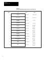
Table of Contents
Using this Manual . . . . . . . . . . . . . . . . . . . . . . . . . . . . . . . . . .
1-1
1.0 Chapter Objectives . . . . . . . . . . . . . . . . . . . . . . . . . . . . . . . . . . . .
1.1 Manual’s Purpose . . . . . . . . . . . . . . . . . . . . . . . . . . . . . . . . . . . .
1.2 Audience . . . . . . . . . . . . . . . . . . . . . . . . . . . . . . . . . . . . . . . . . . .
1.3 Vocabulary . . . . . . . . . . . . . . . . . . . . . . . . . . . . . . . . . . . . . . . . .
1.4 Important Information . . . . . . . . . . . . . . . . . . . . . . . . . . . . . . . . . .
1.5 Manual Organization . . . . . . . . . . . . . . . . . . . . . . . . . . . . . . . . . .
1-1
1-1
1-1
1-2
1-2
1-3
Introduction to Programming PLC-3 Family Controllers . . . . .
2-1
2.0 Chapter Objectives . . . . . . . . . . . . . . . . . . . . . . . . . . . . . . . . . . . .
2.1 Storing Information in the Controller . . . . . . . . . . . . . . . . . . . . . . . .
2.2 Interface Between Ladder Program and Hardware . . . . . . . . . . . . .
2.2.1 I/O Image Tables in the Data Table . . . . . . . . . . . . . . . . . . . . . . .
2.2.2 Addressing Instructions . . . . . . . . . . . . . . . . . . . . . . . . . . . . . . .
2.2.3 Operation of the Ladder Program . . . . . . . . . . . . . . . . . . . . . . . .
2.3 Organization of Memory . . . . . . . . . . . . . . . . . . . . . . . . . . . . . . . .
2.3.1 System Status (Area 0) . . . . . . . . . . . . . . . . . . . . . . . . . . . . . . .
2.3.2 System Pointers (Area 1) . . . . . . . . . . . . . . . . . . . . . . . . . . . . . .
2.3.3 Module Status (Area 2) . . . . . . . . . . . . . . . . . . . . . . . . . . . . . . .
2.3.4 Data Table (Area 3) . . . . . . . . . . . . . . . . . . . . . . . . . . . . . . . . . .
2.3.5 Ladder Program (Area 4) . . . . . . . . . . . . . . . . . . . . . . . . . . . . . .
2.3.6 Message (Area 5) . . . . . . . . . . . . . . . . . . . . . . . . . . . . . . . . . . .
2.3.7 System Symbols (Area 6) . . . . . . . . . . . . . . . . . . . . . . . . . . . . . .
2.3.8 System Scratchpad (Area 7) . . . . . . . . . . . . . . . . . . . . . . . . . . . .
2.3.9 Converted Procedures (Area 8) . . . . . . . . . . . . . . . . . . . . . . . . .
2.3.10 Force Table (Area 10) . . . . . . . . . . . . . . . . . . . . . . . . . . . . . . .
2.3.11 Free Memory (Area 60) . . . . . . . . . . . . . . . . . . . . . . . . . . . . . .
2.3.12 Reserved Areas and End of Memory . . . . . . . . . . . . . . . . . . . . .
2-1
2-1
2-3
2-3
2-3
2-4
2-5
2-5
2-6
2-6
2-6
2-7
2-7
2-7
2-7
2-7
2-7
2-8
2-8
Using the Data Table . . . . . . . . . . . . . . . . . . . . . . . . . . . . . . . .
3-1
3.0 Chapter Objectives . . . . . . . . . . . . . . . . . . . . . . . . . . . . . . . . . . . .
3.1 What is the Data Table? . . . . . . . . . . . . . . . . . . . . . . . . . . . . . . . .
3.2 Input/Output Status . . . . . . . . . . . . . . . . . . . . . . . . . . . . . . . . . . .
3.2.1 Output Image Table . . . . . . . . . . . . . . . . . . . . . . . . . . . . . . . . . .
3.2.2 Input Image Table . . . . . . . . . . . . . . . . . . . . . . . . . . . . . . . . . . .
3.3 Timer and Counter Data . . . . . . . . . . . . . . . . . . . . . . . . . . . . . . . .
3.3.1 Timer Table . . . . . . . . . . . . . . . . . . . . . . . . . . . . . . . . . . . . . . . .
3.3.2 Counter Table . . . . . . . . . . . . . . . . . . . . . . . . . . . . . . . . . . . . . .
3.4 Numeric and Alphanumeric Data . . . . . . . . . . . . . . . . . . . . . . . . . .
3.4.1 Integer Table . . . . . . . . . . . . . . . . . . . . . . . . . . . . . . . . . . . . . . .
3.4.2 Floating-point Table . . . . . . . . . . . . . . . . . . . . . . . . . . . . . . . . . .
3.4.3 Decimal Table . . . . . . . . . . . . . . . . . . . . . . . . . . . . . . . . . . . . . .
3.4.4 Binary Table . . . . . . . . . . . . . . . . . . . . . . . . . . . . . . . . . . . . . . .
3.4.5 ASCII Table . . . . . . . . . . . . . . . . . . . . . . . . . . . . . . . . . . . . . . . .
3-1
3-1
3-1
3-3
3-4
3-6
3-6
3-6
3-7
3-7
3-7
3-7
3-7
3-8
i
Table of Contents
ii
3.4.6 High-order-integer Table . . . . . . . . . . . . . . . . . . . . . . . . . . . . . . .
3.5 Other Data Table Sections . . . . . . . . . . . . . . . . . . . . . . . . . . . . . .
3.5.1 Pointers . . . . . . . . . . . . . . . . . . . . . . . . . . . . . . . . . . . . . . . . . .
3.5.2 Status . . . . . . . . . . . . . . . . . . . . . . . . . . . . . . . . . . . . . . . . . . . .
3-8
3-8
3-8
3-8
Getting Started . . . . . . . . . . . . . . . . . . . . . . . . . . . . . . . . . . . .
4-1
4.0 Chapter Objectives . . . . . . . . . . . . . . . . . . . . . . . . . . . . . . . . . . . .
4.1 What is a Logic Rung? . . . . . . . . . . . . . . . . . . . . . . . . . . . . . . . . .
4.1.1 Identifying I/O Locations . . . . . . . . . . . . . . . . . . . . . . . . . . . . . . .
4.2 Using Relay-type Instructions . . . . . . . . . . . . . . . . . . . . . . . . . . . .
4.2.1 Examine On (XIC) . . . . . . . . . . . . . . . . . . . . . . . . . . . . . . . . . . .
4.2.2 Examine Off (XIO) . . . . . . . . . . . . . . . . . . . . . . . . . . . . . . . . . . .
4.2.3 Output Energize (OTE) . . . . . . . . . . . . . . . . . . . . . . . . . . . . . . .
4.3 Preparing to Program the Processor . . . . . . . . . . . . . . . . . . . . . . .
4.3.1 Modes of Operation . . . . . . . . . . . . . . . . . . . . . . . . . . . . . . . . . .
4.3.2 A Simple Rung . . . . . . . . . . . . . . . . . . . . . . . . . . . . . . . . . . . . .
4.3.3 A Simple Rung with Multiple Inputs . . . . . . . . . . . . . . . . . . . . . . .
4.3.4 A Simple Rung with the Examine-off Instruction . . . . . . . . . . . . . .
4.3.5 Examining Output Bits . . . . . . . . . . . . . . . . . . . . . . . . . . . . . . . .
4.4 Using Branch Instructions . . . . . . . . . . . . . . . . . . . . . . . . . . . . . . .
4.4.1 A Rung with a Hold-in Branch . . . . . . . . . . . . . . . . . . . . . . . . . . .
4.4.2 A Rung with an Input Branch within a Branch . . . . . . . . . . . . . . . .
4.5 Using Retentive Relay-type Instructions (OTL, OTU) . . . . . . . . . . . .
4-1
4-1
4-2
4-11
4-11
4-11
4-12
4-12
4-13
4-14
4-14
4-15
4-15
4-16
4-17
4-18
4-18
Using Timers and Counters . . . . . . . . . . . . . . . . . . . . . . . . . . .
5-1
5.0 Chapter Objectives . . . . . . . . . . . . . . . . . . . . . . . . . . . . . . . . . . . .
5.1 Using Timers . . . . . . . . . . . . . . . . . . . . . . . . . . . . . . . . . . . . . . . .
5.1.1 Selecting a Time Base . . . . . . . . . . . . . . . . . . . . . . . . . . . . . . . .
5.1.2 Timer Accuracy . . . . . . . . . . . . . . . . . . . . . . . . . . . . . . . . . . . . .
5.2 Using Timer Instructions . . . . . . . . . . . . . . . . . . . . . . . . . . . . . . . .
5.2.1 Timer On-delay (TON) . . . . . . . . . . . . . . . . . . . . . . . . . . . . . . . .
5.2.2 Timer Off-delay (TOF) . . . . . . . . . . . . . . . . . . . . . . . . . . . . . . . .
5.2.3 Retentive Timer On-delay (RTO) . . . . . . . . . . . . . . . . . . . . . . . . .
5.2.4 Timer One-shot (TOS) . . . . . . . . . . . . . . . . . . . . . . . . . . . . . . . .
5.3 Using Counters . . . . . . . . . . . . . . . . . . . . . . . . . . . . . . . . . . . . . .
5.4 Using Counter Instructions . . . . . . . . . . . . . . . . . . . . . . . . . . . . . .
5.4.1 Counter Up (CTU) . . . . . . . . . . . . . . . . . . . . . . . . . . . . . . . . . . .
5.4.2 Counter Down (CTD) . . . . . . . . . . . . . . . . . . . . . . . . . . . . . . . . .
5.5 Resetting Timers and Counter (RES) . . . . . . . . . . . . . . . . . . . . . . .
5.6 Cascading Timers and Counters . . . . . . . . . . . . . . . . . . . . . . . . . .
5-1
5-1
5-3
5-4
5-5
5-5
5-7
5-9
5-10
5-12
5-15
5-16
5-18
5-21
5-21
Table of Contents
Using Data-manipulation Instructions . . . . . . . . . . . . . . . . . . .
6-1
6.0 Chapter Objectives . . . . . . . . . . . . . . . . . . . . . . . . . . . . . . . . . . . .
6.1 Data Manipulation . . . . . . . . . . . . . . . . . . . . . . . . . . . . . . . . . . . .
6.2 Data-transfer Instructions . . . . . . . . . . . . . . . . . . . . . . . . . . . . . . .
6.2.1 Move (MOV) . . . . . . . . . . . . . . . . . . . . . . . . . . . . . . . . . . . . . . .
6.2.2 Move with Mask (MVM) . . . . . . . . . . . . . . . . . . . . . . . . . . . . . . .
6.2.3 Move Status (MVS) . . . . . . . . . . . . . . . . . . . . . . . . . . . . . . . . . .
6.3 Data-comparison Instructions . . . . . . . . . . . . . . . . . . . . . . . . . . . .
6.3.1 Equal To (EQU) . . . . . . . . . . . . . . . . . . . . . . . . . . . . . . . . . . . . .
6.3.2 Not Equal To (NEQ) . . . . . . . . . . . . . . . . . . . . . . . . . . . . . . . . . .
6.3.3 Greater Than (GRT) . . . . . . . . . . . . . . . . . . . . . . . . . . . . . . . . .
6.3.4 Greater Than or Equal To (GEQ) . . . . . . . . . . . . . . . . . . . . . . . . .
6.3.5 Less Than (LES) . . . . . . . . . . . . . . . . . . . . . . . . . . . . . . . . . . . .
6.3.6 Less Than or Equal To (LEQ) . . . . . . . . . . . . . . . . . . . . . . . . . . .
6.3.7 Limit (LIM) . . . . . . . . . . . . . . . . . . . . . . . . . . . . . . . . . . . . . . . .
6.4 Arithmetic Instructions . . . . . . . . . . . . . . . . . . . . . . . . . . . . . . . . .
6.4.1 Add (ADD) . . . . . . . . . . . . . . . . . . . . . . . . . . . . . . . . . . . . . . . .
6.4.2 Subtract (SUB) . . . . . . . . . . . . . . . . . . . . . . . . . . . . . . . . . . . . .
6.4.3 Multiply (MUL) . . . . . . . . . . . . . . . . . . . . . . . . . . . . . . . . . . . . . .
6.4.4 Divide (DIV) . . . . . . . . . . . . . . . . . . . . . . . . . . . . . . . . . . . . . . .
6.4.5 Square Root (SQR) . . . . . . . . . . . . . . . . . . . . . . . . . . . . . . . . . .
6.4.6 Negate (NEG) . . . . . . . . . . . . . . . . . . . . . . . . . . . . . . . . . . . . . .
6.5 Logic Instructions . . . . . . . . . . . . . . . . . . . . . . . . . . . . . . . . . . . . .
6.5.1 AND (AND) . . . . . . . . . . . . . . . . . . . . . . . . . . . . . . . . . . . . . . . .
6.5.2 OR (OR) . . . . . . . . . . . . . . . . . . . . . . . . . . . . . . . . . . . . . . . . . .
6.5.3 XOR (XOR) . . . . . . . . . . . . . . . . . . . . . . . . . . . . . . . . . . . . . . .
6.5.4 NOT (NOT) . . . . . . . . . . . . . . . . . . . . . . . . . . . . . . . . . . . . . . . .
6-1
6-1
6-4
6-5
6-5
6-7
6-8
6-8
6-9
6-9
6-10
6-11
6-11
6-12
6-13
6-14
6-15
6-16
6-17
6-18
6-19
6-20
6-21
6-22
6-23
6-24
Using Files . . . . . . . . . . . . . . . . . . . . . . . . . . . . . . . . . . . . . . .
7-1
7.0 Chapter Objectives . . . . . . . . . . . . . . . . . . . . . . . . . . . . . . . . . . . .
7.1 Defining a File . . . . . . . . . . . . . . . . . . . . . . . . . . . . . . . . . . . . . . .
7.2 Creating and Addressing Files . . . . . . . . . . . . . . . . . . . . . . . . . . . .
7.2.1 Addressing a Word within a File . . . . . . . . . . . . . . . . . . . . . . . . .
7.2.2 Addressing a Group of Words within a File . . . . . . . . . . . . . . . . . .
7.2.3 Addressing a Bit within a File . . . . . . . . . . . . . . . . . . . . . . . . . . .
7.2.4 Addressing File 0 . . . . . . . . . . . . . . . . . . . . . . . . . . . . . . . . . . . .
7.2.5 Addressing Timers, Counters, and Pointers Using Files . . . . . . . .
7.3 File Operation . . . . . . . . . . . . . . . . . . . . . . . . . . . . . . . . . . . . . . .
7.3.1 Counter Operation for File Instructions . . . . . . . . . . . . . . . . . . . .
7.3.2 File Mode Operation . . . . . . . . . . . . . . . . . . . . . . . . . . . . . . . . .
7-1
7-1
7-3
7-6
7-7
7-8
7-10
7-11
7-13
7-14
7-15
iii
Table of Contents
iv
Using Data-manipulation Instructions with Files . . . . . . . . . . .
8-1
8.0 Chapter Objectives . . . . . . . . . . . . . . . . . . . . . . . . . . . . . . . . . . . .
8.1 Data Manipulation with Files . . . . . . . . . . . . . . . . . . . . . . . . . . . . .
8.2 File-data-transfer Instructions . . . . . . . . . . . . . . . . . . . . . . . . . . . .
8.2.1 File Move (MVF) . . . . . . . . . . . . . . . . . . . . . . . . . . . . . . . . . . . .
8.2.2 File Move with Mask (MMF) . . . . . . . . . . . . . . . . . . . . . . . . . . . .
8.3 File-data-comparison Instructions . . . . . . . . . . . . . . . . . . . . . . . . .
8.3.1 Search Equal (SEQ) . . . . . . . . . . . . . . . . . . . . . . . . . . . . . . . . .
8.3.2 Search Not Equal (SNE) . . . . . . . . . . . . . . . . . . . . . . . . . . . . . .
8.3.3 Search Less Than (SLS) . . . . . . . . . . . . . . . . . . . . . . . . . . . . . .
8.3.4 Search Less Than or Equal (SLE) . . . . . . . . . . . . . . . . . . . . . . . .
8.3.5 Search Greater Than (SGR) . . . . . . . . . . . . . . . . . . . . . . . . . . . .
8.3.6 Search Greater Than or Equal (SGE) . . . . . . . . . . . . . . . . . . . . .
8.4 File-arithmetic Instructions . . . . . . . . . . . . . . . . . . . . . . . . . . . . . .
8.4.1 File Add (ADF) . . . . . . . . . . . . . . . . . . . . . . . . . . . . . . . . . . . . .
8.4.2 File Subtract (SBF) . . . . . . . . . . . . . . . . . . . . . . . . . . . . . . . . . .
8.4.3 File Multiply (MLF) . . . . . . . . . . . . . . . . . . . . . . . . . . . . . . . . . . .
8.4.4 File Divide (DVF) . . . . . . . . . . . . . . . . . . . . . . . . . . . . . . . . . . . .
8.4.5 File Square Root (SQF) . . . . . . . . . . . . . . . . . . . . . . . . . . . . . . .
8.4.6 File Negate (NGF) . . . . . . . . . . . . . . . . . . . . . . . . . . . . . . . . . . .
8.5 File-logic Instructions . . . . . . . . . . . . . . . . . . . . . . . . . . . . . . . . . .
8.5.1 File AND (ANF) . . . . . . . . . . . . . . . . . . . . . . . . . . . . . . . . . . . . .
8.5.2 File OR (ORF) . . . . . . . . . . . . . . . . . . . . . . . . . . . . . . . . . . . . . .
8.5.3 File XOR (XOF) . . . . . . . . . . . . . . . . . . . . . . . . . . . . . . . . . . . . .
8.5.4 File NOT (NTF) . . . . . . . . . . . . . . . . . . . . . . . . . . . . . . . . . . . . .
8-1
8-1
8-5
8-6
8-12
8-14
8-15
8-17
8-19
8-21
8-23
8-25
8-27
8-28
8-30
8-32
8-34
8-36
8-38
8-40
8-41
8-43
8-45
8-47
Using Shift Registers . . . . . . . . . . . . . . . . . . . . . . . . . . . . . . .
9-1
9.0 Chapter Objectives . . . . . . . . . . . . . . . . . . . . . . . . . . . . . . . . . . . .
9.1 Applying Shift Registers . . . . . . . . . . . . . . . . . . . . . . . . . . . . . . . .
9.2 Using Bit Shift Instructions . . . . . . . . . . . . . . . . . . . . . . . . . . . . . .
9.2.1 Counter Operation for Bit Shift Instructions . . . . . . . . . . . . . . . . .
9.2.2 Bit Shift Left (BSL) . . . . . . . . . . . . . . . . . . . . . . . . . . . . . . . . . . .
9.2.3 Bit Shift Right (BSR) . . . . . . . . . . . . . . . . . . . . . . . . . . . . . . . . .
9.3 Using FIFO Instructions . . . . . . . . . . . . . . . . . . . . . . . . . . . . . . . .
9.3.1 Counter Operation for FIFO Instructions . . . . . . . . . . . . . . . . . . .
9.3.2 FIFO Load (FFL) . . . . . . . . . . . . . . . . . . . . . . . . . . . . . . . . . . . .
9.3.3 FIFO Unload (FFU) . . . . . . . . . . . . . . . . . . . . . . . . . . . . . . . . . .
9.4 Example Program . . . . . . . . . . . . . . . . . . . . . . . . . . . . . . . . . . . .
9-1
9-1
9-2
9-5
9-6
9-7
9-8
9-9
9-10
9-11
9-12
Table of Contents
Indexing Bits within Files . . . . . . . . . . . . . . . . . . . . . . . . . . . .
10-1
10.0 Chapter Objectives . . . . . . . . . . . . . . . . . . . . . . . . . . . . . . . . . . .
10.1 Using Indexed-logic Instructions . . . . . . . . . . . . . . . . . . . . . . . . .
10.1.1 Examine Indexed Bit On (XIN) . . . . . . . . . . . . . . . . . . . . . . . . .
10.1.2 Examine Indexed Bit Off (XIF) . . . . . . . . . . . . . . . . . . . . . . . . . .
10.1.3 Indexed Bit On (BIN) . . . . . . . . . . . . . . . . . . . . . . . . . . . . . . . .
10.1.4 Using Retentive Indexed-logic Instructions (BIS, BIR) . . . . . . . . .
10.2 Example Program . . . . . . . . . . . . . . . . . . . . . . . . . . . . . . . . . . . .
10-1
10-1
10-4
10-5
10-6
10-7
10-9
Using Pointers for Indirect Addressing . . . . . . . . . . . . . . . . . .
11-1
11.0 Chapter Objectives . . . . . . . . . . . . . . . . . . . . . . . . . . . . . . . . . . .
11.1 Applying Pointers . . . . . . . . . . . . . . . . . . . . . . . . . . . . . . . . . . . .
11.2 Pointer Operation . . . . . . . . . . . . . . . . . . . . . . . . . . . . . . . . . . . .
11.2.1 Locating a Word Inside of a File . . . . . . . . . . . . . . . . . . . . . . . .
11.2.2 Locating a File Starting at a Certain Word Address . . . . . . . . . . .
11.2.3 Pointer Operation for Timers and Counters . . . . . . . . . . . . . . . .
11.2.4 Nested Pointer Operation . . . . . . . . . . . . . . . . . . . . . . . . . . . . .
11.3 Example Pointer Using Pointers . . . . . . . . . . . . . . . . . . . . . . . . . .
11.3.1 The Advantage of Using Pointers . . . . . . . . . . . . . . . . . . . . . . .
11.4 Programming Considerations for Pointers . . . . . . . . . . . . . . . . . . .
11-1
11-1
11-1
11-4
11-6
11-7
11-8
11-9
11-14
11-15
Using Diagnostic Instructions . . . . . . . . . . . . . . . . . . . . . . . . .
12-1
12.0 Chapter Objectives . . . . . . . . . . . . . . . . . . . . . . . . . . . . . . . . . . .
12.1 Applying Diagnostics . . . . . . . . . . . . . . . . . . . . . . . . . . . . . . . . .
12.1.1 Counter Operation for Diagnostic Instructions . . . . . . . . . . . . . . .
12.1.2 File Bit Compare (FBC) . . . . . . . . . . . . . . . . . . . . . . . . . . . . . .
12.1.3 Diagnostic Detect (DDT) . . . . . . . . . . . . . . . . . . . . . . . . . . . . . .
12.2 PLC-3 Event Driven/Change of State Diagnostic Routine . . . . . . . .
12.2.1 Current Cycle Monitoring Logic (Rungs RM0 to RM5) . . . . . . . . .
12.2.2 Teach Logic (Rungs RM6 and RM7) . . . . . . . . . . . . . . . . . . . . .
12.2.3 Fault Detection/Search Logic (Rungs RM8 to RM 10, RS0 to RS15)
12.2.4 Multiple Machine Sequences . . . . . . . . . . . . . . . . . . . . . . . . . .
12.2.5 Generating Reports on Input Faults . . . . . . . . . . . . . . . . . . . . . .
12-1
12-1
12-2
12-3
12-5
12-6
12-17
12-19
12-19
12-21
12-24
v
Table of Contents
vi
Controlling Ladder Program Execution . . . . . . . . . . . . . . . . . .
13-1
13.0 Chapter Objectives . . . . . . . . . . . . . . . . . . . . . . . . . . . . . . . . . . .
13.1 Applying Program Control Instructions . . . . . . . . . . . . . . . . . . . . .
13.1.1 Master Control Reset (MCR) . . . . . . . . . . . . . . . . . . . . . . . . . .
13.1.2 Jump to Label (JMP) . . . . . . . . . . . . . . . . . . . . . . . . . . . . . . . .
13.1.3 Label (LBL) . . . . . . . . . . . . . . . . . . . . . . . . . . . . . . . . . . . . . . .
13.1.4 Jump to Subroutine (JSR) . . . . . . . . . . . . . . . . . . . . . . . . . . . .
13.1.5 Return (RET) . . . . . . . . . . . . . . . . . . . . . . . . . . . . . . . . . . . . . .
13.1.6 No Operation (NOP) . . . . . . . . . . . . . . . . . . . . . . . . . . . . . . . .
13.1.7 End (END) . . . . . . . . . . . . . . . . . . . . . . . . . . . . . . . . . . . . . . .
13.2 Recovering from Major Faults . . . . . . . . . . . . . . . . . . . . . . . . . . .
13.2.1 Using a Fault Routine . . . . . . . . . . . . . . . . . . . . . . . . . . . . . . . .
13.2.2 Using the Clear Fault Command . . . . . . . . . . . . . . . . . . . . . . . .
13.3 Real-time Interrupt . . . . . . . . . . . . . . . . . . . . . . . . . . . . . . . . . . .
13.3.1 Calculating the Interrupt Interval . . . . . . . . . . . . . . . . . . . . . . . .
13.4 Switching Contexts . . . . . . . . . . . . . . . . . . . . . . . . . . . . . . . . . . .
13-1
13-1
13-2
13-4
13-5
13-6
13-8
13-8
13-9
13-10
13-10
13-13
13-14
13-15
13-16
Addressing Memory and Monitoring Controller Status . . . . . .
14-1
14.0 Chapter Objectives . . . . . . . . . . . . . . . . . . . . . . . . . . . . . . . . . . .
14.1 Using Extended Addressing . . . . . . . . . . . . . . . . . . . . . . . . . . . .
14.1.1 System Status . . . . . . . . . . . . . . . . . . . . . . . . . . . . . . . . . . . . .
14.1.2 Module Status . . . . . . . . . . . . . . . . . . . . . . . . . . . . . . . . . . . . .
14.1.3 Data Table . . . . . . . . . . . . . . . . . . . . . . . . . . . . . . . . . . . . . . .
14.1.4 Ladder Program . . . . . . . . . . . . . . . . . . . . . . . . . . . . . . . . . . .
14.1.5 Message . . . . . . . . . . . . . . . . . . . . . . . . . . . . . . . . . . . . . . . . .
14.1.6 System Symbols . . . . . . . . . . . . . . . . . . . . . . . . . . . . . . . . . . .
14.1.7 Converted Procedures . . . . . . . . . . . . . . . . . . . . . . . . . . . . . . .
14.1.8 Force Tables . . . . . . . . . . . . . . . . . . . . . . . . . . . . . . . . . . . . . .
14.2 Using the Data Table Status Files . . . . . . . . . . . . . . . . . . . . . . . .
14.2.1 Fault, Operating Mode, and Program Checksum Status
(Status File 0) . . . . . . . . . . . . . . . . . . . . . . . . . . . . . . . . . . . . . . .
14.2.2 Time-of-Day Clock and Calendar (Status File 1) . . . . . . . . . . . . .
14.2.3 I/O Adapter Module Faults (Status File 2) . . . . . . . . . . . . . . . . . .
14.2.4 I/O Communication Retry Counts (Status File 3) . . . . . . . . . . . . .
14.2.5 1775-MX Module (Status File 4) and 1775-GA Module
(Status Files 11 to 25) . . . . . . . . . . . . . . . . . . . . . . . . . . . . . . . . . .
14-1
14-1
14-2
14-4
14-4
14-6
14-7
14-9
14-10
14-11
14-13
14-13
14-20
14-21
14-23
14-25
Table of Contents
Executing Block Transfers . . . . . . . . . . . . . . . . . . . . . . . . . . .
15-1
15.0 Chapter Objectives . . . . . . . . . . . . . . . . . . . . . . . . . . . . . . . . . . .
15.1 Applying Block Transfers . . . . . . . . . . . . . . . . . . . . . . . . . . . . . . .
15.2 Defining Parameters for a Block Transfer . . . . . . . . . . . . . . . . . . .
15.3 Block-transfer Control File . . . . . . . . . . . . . . . . . . . . . . . . . . . . . .
15.3.1 Block-transfer Status Word . . . . . . . . . . . . . . . . . . . . . . . . . . . .
15.3.2 I/O Module Location Word . . . . . . . . . . . . . . . . . . . . . . . . . . . .
15.3.3 Block-transfer-write Information . . . . . . . . . . . . . . . . . . . . . . . . .
15.3.4 Block-transfer-read Information . . . . . . . . . . . . . . . . . . . . . . . . .
15.4 Block-transfer Instruction Operation . . . . . . . . . . . . . . . . . . . . . . .
15.4.1 Executing a Block-transfer Read (BTR) . . . . . . . . . . . . . . . . . . .
15.4.2 Executing a Block-transfer Write (BTW) . . . . . . . . . . . . . . . . . . .
15.4.3 Executing a Bidirectional Block Transfer . . . . . . . . . . . . . . . . . .
15.4.4 Block-transfer Size Limit for 1775-S4A, -S4B, and -SR Scanners .
15.4.5 Example Block-transfer Diagnostic Program . . . . . . . . . . . . . . .
15.5 Troubleshooting Block-transfer Errors . . . . . . . . . . . . . . . . . . . . .
15-1
15-1
15-3
15-4
15-4
15-6
15-6
15-6
15-6
15-9
15-12
15-13
15-13
15-14
15-16
Using the Message Instruction . . . . . . . . . . . . . . . . . . . . . . . .
16-1
16.0 Chapter Objectives . . . . . . . . . . . . . . . . . . . . . . . . . . . . . . . . . . .
16.1 Applying the Message Instruction . . . . . . . . . . . . . . . . . . . . . . . . .
16.2 Message Control File . . . . . . . . . . . . . . . . . . . . . . . . . . . . . . . . .
16.2.1 Message Status Word . . . . . . . . . . . . . . . . . . . . . . . . . . . . . . .
16.2.2 Message Type Word . . . . . . . . . . . . . . . . . . . . . . . . . . . . . . . .
16.2.3 Module Extended Address . . . . . . . . . . . . . . . . . . . . . . . . . . . .
16.2.4 Message Contents . . . . . . . . . . . . . . . . . . . . . . . . . . . . . . . . . .
16.3 Using the Message Instruction (MSG) . . . . . . . . . . . . . . . . . . . . .
16.4 Message Categories . . . . . . . . . . . . . . . . . . . . . . . . . . . . . . . . . .
16.4.1 Report Generation or GA Basic Procedures . . . . . . . . . . . . . . . .
16.4.2 Rung Comments . . . . . . . . . . . . . . . . . . . . . . . . . . . . . . . . . . .
16.4.3 Terminal Messages (MACROS) . . . . . . . . . . . . . . . . . . . . . . . .
16.4.4 Data Highway Procedures . . . . . . . . . . . . . . . . . . . . . . . . . . . .
16.4.5 Assistance Messages (HELP) . . . . . . . . . . . . . . . . . . . . . . . . . .
16.5 Using Symbols . . . . . . . . . . . . . . . . . . . . . . . . . . . . . . . . . . . . . .
16-1
16-1
16-2
16-2
16-2
16-4
16-4
16-4
16-8
16-9
16-9
16-9
16-9
16-10
16-10
vii
Table of Contents
viii
Writing the Ladder Program . . . . . . . . . . . . . . . . . . . . . . . . . .
17-1
17.0 Chapter Objectives . . . . . . . . . . . . . . . . . . . . . . . . . . . . . . . . . . .
17.1 Evaluating the Process . . . . . . . . . . . . . . . . . . . . . . . . . . . . . . . .
17.2 Assigning the I/O Addresses . . . . . . . . . . . . . . . . . . . . . . . . . . . .
17.3 Assigning Internal Storage Addresses . . . . . . . . . . . . . . . . . . . . .
17.4 Evaluating Application Considerations . . . . . . . . . . . . . . . . . . . . .
17.4.1 Short Pulses . . . . . . . . . . . . . . . . . . . . . . . . . . . . . . . . . . . . . .
17.4.2 Orderly Shutdowns . . . . . . . . . . . . . . . . . . . . . . . . . . . . . . . . .
17.4.3 Diagnostics . . . . . . . . . . . . . . . . . . . . . . . . . . . . . . . . . . . . . . .
17.5 Managing Memory . . . . . . . . . . . . . . . . . . . . . . . . . . . . . . . . . . .
17.6 Example Program . . . . . . . . . . . . . . . . . . . . . . . . . . . . . . . . . . . .
17.6.1 Separating Good Parts . . . . . . . . . . . . . . . . . . . . . . . . . . . . . . .
17.6.2 Separating Bad Parts . . . . . . . . . . . . . . . . . . . . . . . . . . . . . . . .
17.6.3 Conveyor Operation for Good Parts . . . . . . . . . . . . . . . . . . . . . .
17.6.4 Developing the Ladder Program . . . . . . . . . . . . . . . . . . . . . . . .
17-1
17-1
17-1
17-1
17-2
17-2
17-3
17-3
17-3
17-3
17-5
17-5
17-5
17-6
Instruction Set Execution Times and Memory Usage . . . . . . . .
A-1
A.0 Introduction . . . . . . . . . . . . . . . . . . . . . . . . . . . . . . . . . . . . . . . . .
A-1
Numbering Systems . . . . . . . . . . . . . . . . . . . . . . . . . . . . . . . .
B-1
B.0 Introduction . . . . . . . . . . . . . . . . . . . . . . . . . . . . . . . . . . . . . . . . .
B.1 Binary . . . . . . . . . . . . . . . . . . . . . . . . . . . . . . . . . . . . . . . . . . . . .
B.2 Decimal . . . . . . . . . . . . . . . . . . . . . . . . . . . . . . . . . . . . . . . . . . .
B.3 Binary Coded Decimal . . . . . . . . . . . . . . . . . . . . . . . . . . . . . . . . .
B.4 Hexadecimal . . . . . . . . . . . . . . . . . . . . . . . . . . . . . . . . . . . . . . . .
B.5 Octal . . . . . . . . . . . . . . . . . . . . . . . . . . . . . . . . . . . . . . . . . . . . . .
B.6 Integer . . . . . . . . . . . . . . . . . . . . . . . . . . . . . . . . . . . . . . . . . . . .
B.7 Floating Point . . . . . . . . . . . . . . . . . . . . . . . . . . . . . . . . . . . . . . .
B.8 Using the Conversion Tables . . . . . . . . . . . . . . . . . . . . . . . . . . . . .
B-1
B-1
B-2
B-3
B-3
B-4
B-5
B-7
B-7
Memory Management Forms . . . . . . . . . . . . . . . . . . . . . . . . . .
C-1
C.0 Introduction . . . . . . . . . . . . . . . . . . . . . . . . . . . . . . . . . . . . . . . . .
C-1
Using the Instruction Set . . . . . . . . . . . . . . . . . . . . . . . . . . . . .
D-1
D.0 Introduction . . . . . . . . . . . . . . . . . . . . . . . . . . . . . . . . . . . . . . . . .
D-1
Chapter
1
Using this Manual
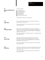
1.0
Chapter Objectives
After reading this chapter you should know:
what the manual contains
who the manual is written for
how the manual is organized
This chapter tells you how to use this manual properly and efficiently for
the tasks you have to do. Read this chapter before you program a PLC-3
family programmable controller.
1.1
Manual’s Purpose
This manual describes the concepts behind programming PLC-3 family
processors. Included in this manual is detailed information on how the
PLC-3 programming instructions work. By using the information presented
in this manual, you should be able to develop ladder-diagram programs to
control your application processes.
This manual does not provide information on loading ladder-diagram
programs into the PLC-3 controller. For detailed information on loading
PLC-3 ladder-diagram programs, refer to the PLC-3 Industrial Terminal
(cat. no. 1770-T4) User’s Manual (publication 1770-6.5.15).
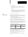
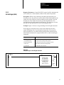
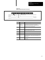
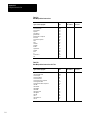
1.2
Audience
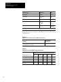
Before attempting to execute programs on a PLC-3 family programmable
controller, you should be familiar with the hardware components and
installation procedures needed to operate the controller. If you are not
familiar with this, you can refer to the following publications:
Publication
Title
1770-6.5.15
PLC-3 Industrial Terminal (Cat. No. 1770-T4) User’s Manual
1775-6.3.1
PLC-3 Backup Concepts Manual
1775-6.5.1
Communication Adapter Module (Cat. No. 1775-KA)
1775-6.5.2
I/O Scanner-Programmer Module (Cat. No. 1775-S4A) User’s Manual
1775-6.5.3
I/O Scanner-Message Handling Module (Cat. No. 1775-S4B) User’s
Manual
1775-6.5.4
Peripheral Communication Module (Cat. No. 1775-GA) User’s Manual
1775-6.7.1
PLC-3 Family Installation and Operation Manual
1-1
Chapter 1
Using this Manual
You can also use our Publication Index (publication SD499) as a guide to
further information about products related to our PLC-3 family of
programmable controllers. Consult your local Allen-Bradley distributor or
sales engineer for information regarding this publication or any needed
information.
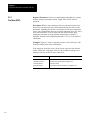
1.3
Vocabulary
We refer to certain types of equipment and terms throughout this manual.
To make the manual easier for you to read and understand, we avoid
repeating full product names where possible.
We refer to the :
PLC-3 or PLC-3/10 programmable controller system as the controller
Processor Module (cat. nos. 1775-L1, -L2, -L3, -L4) as the processor
hardware device used to enter or load ladder-diagram programs into the
PLC-3 processor as the program loader
I/O scanner module (cat. nos. 1775-S5, -S4A, -S4B, -SR5, -SR) that
scans the I/O chassis as the scanner
ladder-diagram or user program that controls PLC-3 processor operation
as the ladder program
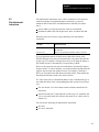
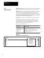
1.4
Important Information
In this manual, there are three different types of important information:
WARNINGS inform you where you could be injured if you do not
follow the written procedure.
CAUTIONS inform you where you could damage your equipment if
you do not follow the written procedure.
IMPORTANTS inform you of exceptions to general rules or remind
you about important information.
1-2
Chapter 1
Using this Manual
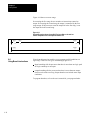
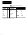
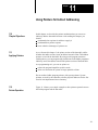
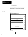
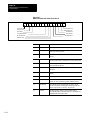
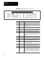
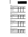
1.5
Manual Organization
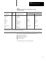
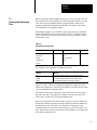
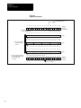
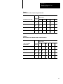
This manual is organized into the following chapters:
Chapter/
Appendix
Title
What is covered
1
Using this Manual
manual’s purpose, audience, vocabulary, design, and lists related publications
2
Intorduction to Programming PLC-3 Family
Controllers
memory organization and concepts used to program the processor
3
Using the Data Table
overview of the data table with a description for each section
4
Getting Started
introduction to the rung, relay-type instructions, I/O addressing formats, modes of
operation, instruction set
5
Using Timers and Counters
how to use timers and counters in the ladder program
6
Using Data Manipulation Instructions
how to use data manipulation instructions in the ladder program
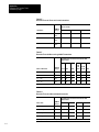
7
Using Files
concept of files for the processor
8
Using Data Manipulation Instructions with Files
how to use data manipulation instructions in the ladder program
9
Using Shift Registers
how to use shift register instructions to program synchronous and asynchronous
shift registers in the ladder program
10
Indexing Bits within Files
concept of decimal bit addressing used with indexed logic instructions in the
ladder program
11
Using Pointers for Indirect Addressing
concept of pointers and how to use pointer instructions in the ladder program
12
Using Diagnostic Instructions
how to use diagnostic instructions in the ladder program
13
Controlling Ladder Program Execution
how to use program control instructions in the ladder program, recovering from
major faults, real-time interrupt, and switching contexts
14
Addressing Memory and Monitoring Controller Status
concept of extended addressing, status bit organization in memory
15
Executing Block Transfers
concept of block transfer and using block-transfer instructions in the ladder
program
16
Using the Message Instruction
how to use the message instruction to execute tasks on other PLC-3 modules
17
Writing the Ladder Program
tips on writing the ladder program
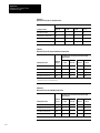
A
Instruction Set Execution Times and Memory Usage
typical times for the processor to execute the instructions and the amount of
memory used for each instruction
B
Numbering Systems
binary, decimal, integer, octal, hexadecimal, high-order integer, and floating-point
numbering systems
C
Memory Management Forms
forms you can use to organize your I/O and data table assignments
D
Glossary
listing of words and definitions pertaining to PLC-3 programming
E
Ladder Instruction Listings
listings of the entire instruction set with abbreviations for each instruction
1-3
Chapter
2
Introduction to Programming
PLC-3 Family Controllers
2.0
Chapter Objectives
This chapter introduces concepts behind programming the controller. In
this chapter we describe the:
definition of memory for the processor
principle sections of memory
organization of memory
2.1
Storing Information in the
Controller
Memory for the processor stores the information necessary for operation.
This information includes the ladder-program instructions and other data.
By monitoring or sending information to memory, you can see or tell the
processor what to do.
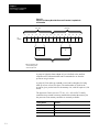
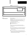
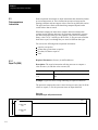
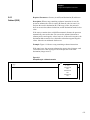
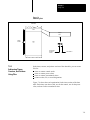
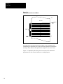
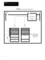
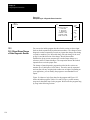
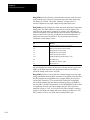
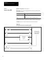
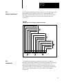
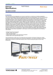
You can think of memory as a large array of storage points. Each separate
storage point is called a BInary digiT or BIT (Figure 2.1). A Bit is the
smallest unit of information that memory can retain. Each bit in memory
stores binary values, or values in base two. Thus, each bit can store:
1, meaning that the bit is on or set
0, meaning that the bit is off or reset
2-1
Chapter 2
Introduction to Programming
PLC-3 Family Controllers
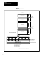
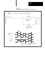
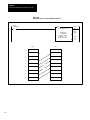
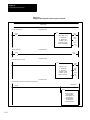
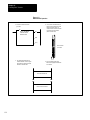
Figure 2.1
Structure of a Memory Word that Stores and Transmits Complete Units
of Information
Upper Byte
Bit
Number 1
17
16
15
14
13
1
0
1
1
1
Lower Byte
12
11
1
0
10
1
07
06
05
04
03
02
01
00
1
1
1
0
0
0
1
0
1
0
‘‘set”
‘‘reset”
Bit
1
Bits are numbered in the
octal numbering system
and move right to left
A group of eight bits forms a byte. A byte is defined as the smallest
complete unit of information that can be transmitted to or from the
processor at a given time.
A group of 6 bits makes up a word. A word can be thought of as being
made up of two or four 8-bit bytes. The total number of words in the
processor gives you the basis for the memory size, with 1K equal to 1,024
words.
The processor Chassis (cat. no 1775-A1, -A2, -A3) for PLC-3 family
controllers must contain a memory module that contains the memory for
the processor. Four memory modules are currently available:
2-2
Catalog Number
Contains
1775-ME4, -MS4
16K or 16,384 words
1775-ME8, -MS8
32K or 32,768 words
1775-MEA, -MSA
64K or 65,536 words
1775-MED
128K or 131,072 words
Chapter 2
Introduction to Programming
PLC-3 Family Controllers
2.2
Interface Between Ladder
Program and Hardware
Later in this chapter we explain the organization of memory. Before doing
so, this section explains how the controller uses machine data, sensed by
1771 input modules to turn output devices on or off with 1771 output
modules. This hardware-program interface occurs between two areas in
memory:
Data table which stores status and numeric data
Ladder program which stores instruction that you use to control your
application
2.2.1
I/O Image Tables in the Data
Table
Within the data table, input and output image tables store the status of
input and output devices connected to 1771 I/O modules. The primary
purpose of the input image table is to duplicate the status of the input
devices wired to 1771 input module terminals:
If the input device is
Then its corresponding input image table bit is
on
set
off
reset
You program instruction in the ladder program to monitor bits in the input
image table.
The purpose of the output image table is to control the status of output
devices wired to 1771 output module terminals:
If an output image bit is
Then its corresponding output device is
set
on
reset
off
You can program instructions in the ladder program to control bits in the
output image table.
2.2.2
Addressing Instructions
In programming instructions, you enter a code or an address that references
an I/O image table location in the data table which corresponds to a
hardware location in a 1771 I/O chassis
We describe instruction addressing in chapters 3 and 4.
2-3
Chapter 2
Introduction to Programming
PLC-3 Family Controllers
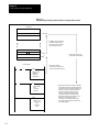
2.2.3
Operation of the Ladder
Program
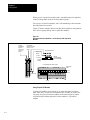
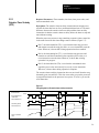
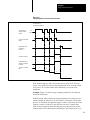
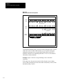
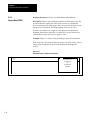
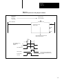
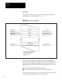
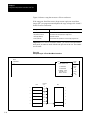
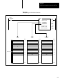
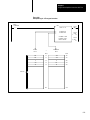
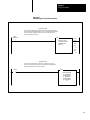
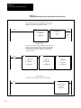
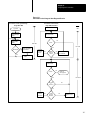
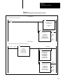
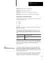
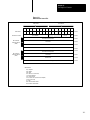
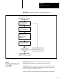
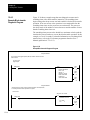
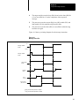
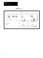
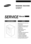
Figure 2.2 illustrates the operational relationship between the input and
output devices, the input and output image tables, and the ladder program.
Figure 2.2
Relating the Ladder Program to the Hardware
Output module in
assigned I/O rack 1,
I/O group 3
I/O image tables in the PLC–3 data table
2–digit bit and
terminal
addresses
3–digit word addresses
17
16
15
14
13
12
11
10
07
06
05
04
03
02
01
00
O0008
1
O0138
Output image table
Input module in
assigned I/O rack 1,
I/O group 2
bit 00 13/00
1
0
1
1
0
1
0
0
0
0
1
0
1
0
0
Output terminal
O013/00
1 = set
0 = reset
O3778
I0008
Input terminal
IO12/10
Outputdevice
turns ON
Input image table
bit IO12/10
0
1
1
0
0
1
0
1
1
1
0
0
0
1
0
1
IO128
1 = set
0 = reset
Input switch
is ON
I3778
Ladder Program Rung
I0012
] [
10
00013
( )
00
When an input switch connected to terminal I12/10 closes, the 1771 input
module circuitry senses a voltage. The scanner reads the input status and
sets input image table bit I12/10. During the program scan, the processor
examines bit I12/10 for a set condition. If the bit is set, the examine on
instruction is logically true, and a path of logic continuity is established
which causes the rung to be true. The processor then sets output image
2-4
Chapter 2
Introduction to Programming
PLC-3 Family Controllers
table bit O13/00 to 1. During the next I/O scan, the processor tells the
output module to turn on output point O13/00, turning on the output device
wired to this terminal.
When an input switch connected to terminal I12/10 opens, the 1771 input
module circuitry senses no voltage. The scanner reads the input status and
resets input image table bit I12/10. During the program scan, the processor
examine bit I12/10 for a set condition. Since the bit is reset, a path of logic
continuity is not established which causes the rung to be false. The
processor then resets output image table bit O13/00 to 0. During the next
I/O scan, the processor tells the output module to turn off output point
O13/00, turning off the output device wired to this terminal.
2.3
Organization of Memory
A memory map is a chart that shows how processor memory is organized.
The processor memory map contains the following areas:
Area
Contents
0
1
2
3
4
5
6
7
8
10
60
63
system status
system pointers
module status
data table
ladder program
message
system symbols
system scratchpad
converted procedures
force table
free memory
end of memory
We describe these memory areas in the following sections.
2.3.1
System Status (Area 0)
The system status area stores data used by the processor to monitor system
operation. If the processor detects a fault condition, it alerts you through
the front panel or CRT on the program loader.
Words in the system status area store the following information:
System counters coordinate the timing of the processor’s response to
requests made by the modules within the processor.
Module identification identifies modules in the processor chassis.
Minor faults are problems that are not serious enough to cause the
processor to stop control action.
2-5
Chapter 2
Introduction to Programming
PLC-3 Family Controllers
Major faults are serous problems that cause the processor to stop control
action.
Controller operation defines various parameters for processor operation
such as the operating mode.
Watchdog timer sets the maximum program scan time.
Time-of-day clock and calendar set the time and date for the processor.
The system status area has a fixed size of 22 words. The remaining
memory areas vary depending on the amount of data that you store in
them.
2.3.2
System Pointers (Area 1)
This area contains the system pointers which are used to define actual
physical address of the first word of each implemented area of memory.
The system pointers function like the individual entries within a table of
contents. Just as each entry in a table of contents tells you the starting page
number for a chapter, each pointer tells the system controller where each
subsection starts in memory.
2.3.3
Module Status (Area 2)
This area describes the modules in the processor and includes the:
2.3.4
Data Table (Area 3)
This area contains information needed to execute the ladder program. This
information includes:
total number of modules in the processor
types of modules and revision levels
fault status of each module
proper module configurations, such as thumbwheel settings,
communication rates, etc.
input/output status
timer and counter data
numeric data
other data used by the ladder program
We describe the contents of the data table in chapter 3.
2-6
Chapter 2
Introduction to Programming
PLC-3 Family Controllers
2.3.5
Ladder Program (Area 4)
This area contains the ladder-program instructions that are scanned and
executed by the processor. The ladder program is divided into three
sections:
main program
subroutine
fault routine
Refer to chapters 4, 13, and 14 respectively.
2.3.6
Message (Area 5)
This area stores messages that you enter into the controller. The processor
can prompt, display, or document these messages. The message area is
divided into five sections:
report generation
rung comments
terminal commands (MACROS)
data highway
assistance (HELP)
2.3.7
System Symbols (Area 6)
This area stores alphanumeric names that represent an address, message, or
report-generation procedure. This area also stores program labels, which
are numbers that you can use to identify parts of the ladder program. We
describe the use of program labels in chapter 13. We describe system
symbols in chapter 14 and 17.
2.3.8
System Scratchpad (Area 7)
This area stores variables used in report generation by the I/O
Scanner-Message Handling Module (cat. no. 1775-S4B).
Important: This section is reserved for processor operation. You cannot
access it when programming.
2.3.9
Converted Procedures
(Area 8)
This area stores the contents of converted procedures used in GA Basic by
the Peripheral Communication Module (cat. no. 1775-GA).
2.3.10
Force Table (Area 10)
This area stores data that reflects forced I/O conditions. You can specify
forced I/O conditions to cause selected input bits to be forced (set or reset)
regardless of the actual condition of corresponding input hardware and
selected output bits to be forced (set or reset) regardless of the output’s
Important: This section is reserved for processor operation. You cannot
access it when programming.
2-7
Chapter 2
Introduction to Programming
PLC-3 Family Controllers
state in the ladder program. You can implement forced I/O through the
program loader or the front panel. Refer to the PLC-3 Programmable
Controller Installation an Operation Manual (publication 1775-6.7.1)
2-8
2.3.11
Free Memory (Area 60)
This area identified the amount of unused memory. You can monitor free
memory by using the memory map feature.
2.3.12
Reserved Areas and
End of Memory
Areas 9 and 11 through 63 are undefined by the processor. The actual end
of memory is area 63.
Important: These sections are reserved for processor operation. You
cannot access them when programming.
Chapter
3
Using the Data Table
3.0
Chapter Objectives
In chapter 2, we introduced the areas that make up memory. In this chapter,
we describe the contents of the data table.
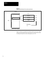
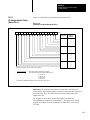
3.1
What is the Data Table?
The data table is a portion of memory that contains the following
information that is used by the processor to execute the ladder program:
input/output status
timer and counter data
numeric data
other data required by the ladder program
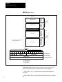
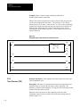
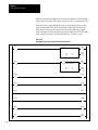
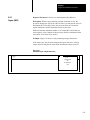
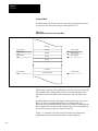
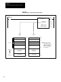
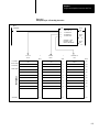
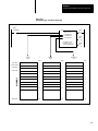
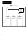
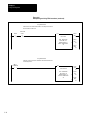
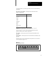
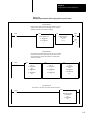
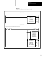
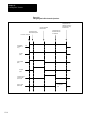
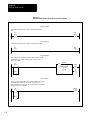
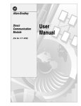
Figure 3.1 shows a map of the sections that make up the data table area.
You can alter the size of each section to meet your application needs.
To address a section, you identify it by entering its section specifier
(Table 3.A). Refer to chapter 14 for detailed information on addressing
memory. Table 3.A also summarizes data types and the acceptable ranges
for storing values in the data table sections.
Important: In addition most data table sections support structures called
files. This chapter does not describe the file structure for the data table
section. For detailed information on using files, refer to chapter 7.
3.2
Input/Output Status
You can monitor the status of I/O points in sections one (output image
table) and two (input image table).
3-1
Chapter 3
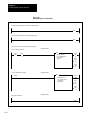
Using the Data Table
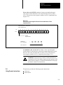
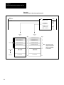
Figure 3.1
PLC-3 Data Table Map Showing the Contents of the Data Table Area
Section
Number
3-2
Title
Maximum
Size
Address
Range
1
Output Image
Table
2
Input Image Table
4,096 values
I00008 to I03778
3
Timer Table
(3 words/timer)
10,000 timers
T0 to T9999
4
Counter Table
(3 words/counter)
10,000 counters
C0 to C9999
5
Integer Table
(1 word/value)
10,000 values
N000:0000 to
N000:9999
6
Floating Point Table
(2 word/value)
10,000 values
F000:0000
to
F000:9999
7
Decimal Table
(1 word/ 4BCD values)
10,000 values
D000:0000
to
D000:9999
8
Binary Table
(1 word/value)
10,000 values
B000:0000
to
B000:9999
9
ASCII Table
(2 Charaacters/word)
20,000 characters
A000:0000
to
A000:9999
10
High–order–integer Table
(2 words/value)
10,000 values
H000:0000
to
H000:9999
12
Pointer
Table
10,000 addresses
P000:0000
to
P000:9999
13
Status
Table
10,000 values
S000:0000
to
S000:9999
4,096 values
O00008 to O03778
Chapter 3
Using the Data Table
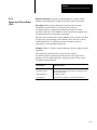
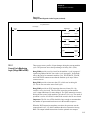
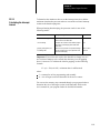
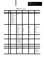
Table 3.A
Section Specifiers, Data Types, and Acceptable Ranges for Values
Stored in the Data Table
Range
Data Table Section
c
Section
Specifier
Type of Data Stored in Section
Low Limit
High Limit
Output image
O
Unsigned binary
0
65,535
Input image
I
Unsigned binary
0
65,535
Timer
T
Unsigned binary
0
65,535
Counter
C
Binary1
-32,768
32,767
Integer
N
Binary1
-32,768
32,767
Floating point
F
Floating point
±2.939 E-39
±1.701 E+38
Decimal
D
Binary coded decimal
0
9,999
Binary
B
Unsigned binary
0
65,535
ASCII2
A
Unsigned binary
–––––
–––––
H
Binary1
High order integer
-2,147,483,648
2,147,483,647
binary3
–––––
–––––
–––––
–––––
Pointer
P
Unsigned
Status
S
Unsigned binary3
1The processor stores positive numbers in straight binary and negative numbers in two’s complement form.
2The ASCII table can store ASCII characters as defined by ASCII (ANSI X3.4).
3The processor treats data in the pointer and status sections as unsigned binary, although these sections are intended to store
3.2.1
Output Image Table
non-numeric data.
This section controls the status of output devices wired to 1771 I/O
modules:
If an output image bit is
Then the corresponding output is
set
on
reset
off
Instructions in the ladder program control these output image bits in the
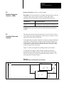
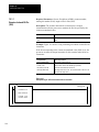
data table.
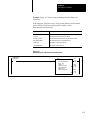
Each bit in the output image table corresponds to a 1771 output module
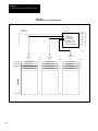
terminal. Figure 3.2 shows the correlation between the image tables and
the 1771 I/O module. Refer to chapter 4 for detailed information on
hardware addressing. To control the maximum amount of I/O points, you
need:
512 words to control 64 racks of I/O for the PLC-3 controller
128 words to control 16 racks of I/O for the PLC-3/10 controller
One assigned I/O rack is equivalent to 128 I/O points. To address a word or
bit in the output image table, use the following address format (Figure 3.3).
3-3
Chapter 3
Using the Data Table
For example, the address O13/01 corresponds to an output terminal located
in a chassis having assigned I/O rack number 1, I/O group 3, terminal 1.
The status of this output is located in word 13, but 1 of the output image
table.
3.2.2
Input Image Table
This section controls the status of input devices wired to 1771 I/O
modules:
If the input switch is
Then the corresponding input bit is
on
set
off
reset
Instructions in the ladder program monitor these input image bits in the
data table.
Each bit in the input image table can correspond to a 1771 input module
terminal. Figure 3.2 shows the correlation between the input image table
and the 1771 input module. Refer to chapter 4 for detailed information on
hardware addressing. To control the maximum amount of I/O points, you
need:
512 words to control 64 racks of I/O for the PLC-3 controller
128 words to control 16 racks of I/O for the PLC-3/10 controller
One assigned I/O rack number is equivalent to 128 I/O points. An I/O rack
could have one or two I/O rack numbers assigned to it. To address a word
or bit in the input image table, use the address format shown in Figure 3.3.
For example, the address I12/01 corresponds to an input terminal located
in a chassis having assigned I/O rack number 1, I/O group 2, terminal 1.
The status of this output is located in word 12, bit 1 of the input image
table.
The address I12/10 corresponds to an input terminal located in a chassis
having assigned I/O rack number 1, I/O group 2, terminal 10. The status of
this input is located in word 12, bit 10 of the input image table.
3-4
Chapter 3
Using the Data Table
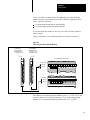
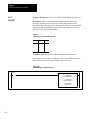
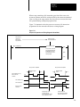
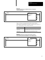
Figure 3.2
Relating an I/O Hardware Location to the Input and Output Image Tables
Data Table
Assigned
I/O Rack
Number 1
I/O Group
Number 2
0
1
2
Output Image Table
3
4
5
6
7
Input Image Table
k
17 16 15 14 13 12 11 10 07 06 05 04 03 02 01 00
Word
I0012
Terminal Number 12
00
01
02
03
04
05
06
07
10
11
12
13
14
15
16
17
3-5
Chapter 3
Using the Data Table
Figure 3.3
I/O Addressing Terminology Between the Hardware and the Data Table
Concept
Example
Module Type
Input (I) or Output(O)
Output Module
Assigned I/O Rack Number
(0–017 for PLC–3/10)
(0–076 for PLC–3)
Assigned I/O
Rack Number 1
I/O Group Number
(0–7)
I/O Group 3
Terminal Number
(00–07 or 10–17)
Data
Table
Section
Word
Address
Bit
Address
Terminal 01
Data
Table
Section
Bit
Address
Word
Address
3.3
Timer and Counter Data
You can use sections three (timer table) and four (counter table) to monitor
timer and counter instruction in the ladder program.
3.3.1
Timer Table
This section monitors the status of timer instructions in the ladder program.
Each timer takes up three words of memory. To address a timer, enter
T<timer number>.
For example, the address T0 corresponds to timer 0. The status of timer 0
is stored in three words in the timer table. We describe the use of these
words in chapter 5.
3.3.2
Counter Table
This section monitors the status of counter instructions in the ladder
program. Each counter takes up three words of memory. To address a
counter, enter C<counter number>.
For example, the address C10 corresponds to counter 10. The status of
counter 10 is stored in the words in the counter table. We describe the use
of these words in chapter 5.
3-6
Chapter 3
Using the Data Table
3.4
Numeric and Alphanumeric
Data
You can use sections:
five (integer table)
six (floating-point table)
seven (decimal table)
eight (binary table)
nine (ASCII table)
ten (high-order-integer table)
to monitor numeric data for the ladder program.
3.4.1
Integer Table
This section stores signed integers in a binary format. To address the
integer table, enter N<word>/<bit>.
For example, the address N33 corresponds to the word 33 in the integer
table of the data table.
3.4.2
Floating-point Table
This section stores signed floating-point values used in sophisticated
arithmetic. Each value can be taken to eight-digit precision, although only
six digits display on the industrial terminal. To address the floating-point
table, enter F<word>/<bit>.
For example, the address F3 corresponds to the word 3 in the floating-point
table of the data table.
3.4.3
Decimal Table
This section stores numeric values that support I/O devices such as
thumbwheel switches and decimal readouts. Each value is stored as a
positive integer in binary coded decimal (BCD) format. To address the
decimal table, enter D<word>/<bit>.
For example, the address D1 corresponds to the word one in the decimal
table of the data table.
3.4.4
Binary Table
This section stores numeric values used in bit and logical operations. Each
value is stored in an unsigned binary format. To address the binary table,
enter B<word>/<bit>.
For example, the address B1 corresponds to the word one in the binary
table of the data table.
3-7
Chapter 3
Using the Data Table
3.4.5
ASCII Table
This section stores alphanumeric data to be processed. The processor stores
ASCII data used as numeric data in an unsigned binary format. The range
for this format is 0 to 65,535. To address the ASCII table, enter
A<word>/<bit>.
For example, the address A4 corresponds to the word four in the ASCII
table of the data table.
3.4.6
High-order-integer Table
This section stores numeric data used in high-precision arithmetic
operations. Each value is stored in a 32-bit signed integer format. To
address the high-order-integer table, enter H<word/bit>.
For example, the address H5 corresponds to the word five in the
high-order-integer table of the data table.
3.5
Other Data Table Sections
The data table also contains sections 12 (pointers) an 13 (status).
3.5.1
Pointers
This section stores address data that you can use for indirect addressing in
the ladder program. That is by using pointers, program logic can change
the address for a particular instruction automatically while the program is
executing. Do not confuse ladder-program pointers with system pointers.
System pointers are used by the controller to define physical addresses for
the first word of each implemented area of memory. Refer to chapter 11 for
detailed information on using pointers.
3.5.2
Status
This section stores status information monitored by the ladder program for
proper operation. The processor transfers this status information from the
system status area of memory to this data table section before it executes
the ladder program. This section stores information on:
major fault status
minor fault status
system operating status
Time-of-day clock and calendar
We describe the organization of the status section in chapter 14.
3-8
Chapter
4
Getting Started
4.0
Chapter Objectives
In this chapter we describe information you need to develop programs for
the controller. After reading this chapter, you should know how to:
use logic rungs to develop the ladder program
identify I/O locations through the ladder program and the data table
execute and monitor the ladder program
use relay-type instructions in the ladder program
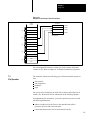
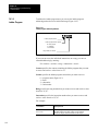
4.1
What is a Logic Rung?
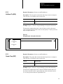
Figure 4.1 shows you a sample logic rung that could be executed by the
processor. A logic rung is a line or segment of the ladder program that
specifies:
the output(s) to be controlled by the processor. These outputs are
identified by bits in the output image table. You program output
instructions on the rung to tell the processor what output to control. The
processor can have more than one output instruction on a rung.
the input condition(s) for the output(s). These inputs are identified by
bits in the input image table. Inputs can be monitored for a set or reset
state. Input instructions on the rung tell the processor when to control
the output.
the path or paths for “logic continuity” to the output. Such paths can
follow series or parallel logic. You can branch instructions to establish
the logic path from the input(s) to the output(s).
4-1
Chapter 4
Getting Started
Figure 4.1
Logic Rung
I0012
] [
10
00013
]/[
05
00013
] [
07
00013
( )
01
I0012
I0012
] [
] [
14
00
I0012
I0012
]/[
10
]/[
11
4.1.1
Identifying I/O Locations
( )
02
Before we describe relay-type instructions, you need to know how to
identify an I/O location in the ladder program. As we stated in chapter 3,
bits in the input image table reflect the status of input devices connected to
input terminals on 1771 input modules, while bits in the output image table
control the status of output devices connected to output terminals on 1771
output modules.
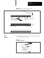
Figure 4.2
Addressing I/O Locations
Assigned I/O Rack No. (000–768)
Data Table\
Section
Specifier
(I = Input)
(O = Output)
I/O Group Number (0–7)
within the
I/O Rack)
Data Table Word Adress
Bit NUmber
Terminal Number (00–17)
within the I/O Group
4-2
00013
Chapter 4
Getting Started
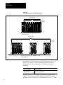
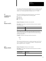
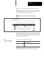
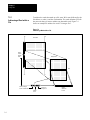
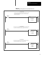
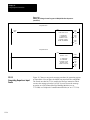
Figure 4.3
An I/O Group Consists of Up to 16 Input Terminals and 16 Output
Termnials
Input
Terminals
Output
Terminals
00
01
02
03
04
05
06
07
10
11
12
13
14
15
16
17
00
01
02
03
04
05
06
07
10
11
12
13
14
15
16
17
A. 2–slot I/O Group
Output
or
Input
Terminals
00
01
02
03
04
05
06
07
10
11
12
13
14
15
16
17
B. 1–slot I/O Group
The controller communicates to these I/O modules through a Remote I/O
Adapter modules (cat. no. 1771-AS, -ASB). To specify I/O locations, you
enter an I/O address in the ladder program that the processor uses in
communicating with the I/O adapter module. Figure 4.2 shows you the
format for such an address.
To specify an I/O address, you need to provide the processor with the
following information:
Terminal – tells the processor the terminal number on the I/O module that
is connected to the input or output device. The terminal number
corresponds to a bit address in the input or output image table.
I/O Group – tells the processor which I/O group within and I/O chassis
contains the I/O module. An I/O group is made up of I/O terminals and can
consist of up to 16 input terminals and/or 16 output terminals (Figure 4.3).
4-3
Chapter 4
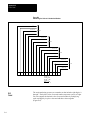
Getting Started
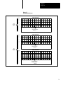
Figure 4.4
An I/O Rack Consists of Up to Eight I/O Groups
Assigned I/O Rack
0
1
2
3
4
5
6
7
I/O Group
NUmber
k
An assigned I/O rack number can represent single I/O chassis
(128 I/O points maxium).
Assigned I/O Rack
0
1
2
3
4
5
6
7
I/O Group
NUmber
An assigned I/O rack number can represent multiple I/O chassis
(128 I/O points maxium).
Depending on your I/O configuration, an I/O group can take up 1/2, 1, or 2
slots in an I/O chassis. We refer to the addressing methods for these
configurations as 1/2-slot addressing, 1-slot addressing, and 2-slot
addressing:
If you are using the
Then you can use
1771-AS adapter
2-slot addressing only
1771-ASB adapter
1/2, 1, or 2-slot addressing
If you are using a 1771-ASB adapter, you select an I/O chassis to have
either 1/2, 1, or 2-slot I/O groups by setting a switch on the I/O chassis
backplane. Refer to the Remote I/O Adapter Module (cat. no. 1771-ASB)
4-4
Chapter 4
Getting Started
User’s Manual (publication 1771-6.5.37) for detailed information on
switch settings.
Rack - tells the processor the assigned rack number of the I/O chassis that
contains the I/O module. A rack is an I/O addressing unit that corresponds
to eight I/O groups (Figure 4.4). Note that a rack of I/O does not
necessarily correspond to one I/O chassis.
2-slot Addressing
When you select 2-slot addressing, the processor addresses two I/O module
slots as one I/O group.
Each physical 2-slot I/O group is represented by a word in the input image
table and a word in the output image table. Each input terminal
corresponds to a bit in the input image table word; each output terminal
corresponds to a bit in the output image table word.
The maximum number of bits available for one 2-slot I/O group is 32; 16
in the input image table and 16 in the output image table.
The type of module that you install determines the number of bits in the
words that are used. You can use either 8 to 16-point I/O modules with
2-slot addressing but not 32-point I/O modules.
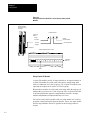
Using 8-point I/O Modules
8-point I/O modules provide eight input or output terminals. Figure 4.5
shows an example address and how that address corresponds to the 2-slot
I/O group concept with an 8-point input module and an 8-point output
module.
4-5
Chapter 4
Getting Started
Figure 4.5
Example Address that Identifies 2-slot I/O Groups with 8-point I/O
Modules
8–point Input
Modules located in
assigned I/O rack 1,
I/O group 0
Example Address
Type of I/O
Module
I = Input
Module
Terminal Number
O = Output
I/O Group Number
I/O Rack
Number
Terminal 12
Corresponding Data Table Location
17 16 15 14 13 12 11 10 07 06 05 04 03 02 01 00
Input Image
Word 1 0
Bit 12
Using 16-point I/O Modules
16-point I/O modules provide 16 input terminals or 16 output terminals. A
16-point I/O module uses a full word in the input or output image table
when it is addressed in a 2-slot I/O group. Two 16-point I/O modules (one
input and one output) can be used in a 2-slot I/O group.
Because these modules use a full word in the image table, the only type of
modules that you can use in a 2-slot I/O group with a 16-point I/O module
is one that performs the opposite (complementary) function. An input
module complements an output module and vice-versa.
You can use an 8-point I/O module with a 16-point module in a 2-slot I/O
group but it must perform the opposite function. That is, one input module
and one output module. However, eight bits in the I/O image table are
unused.
4-6
Chapter 4
Getting Started
Figure 4.6 shows an example address and how that address corresponds to
the 2-slot I/O group concept with a 16-point input module and a 16-point
output module.
Figure 4.6
Example Address that Identifies 2-slot I/O Groups with 16-point I/O
Modules
16–point
Input Module
located in
assigned I/O
rack 1, I/O
group 0
16–point Output Module
located in assigned I/O rack 1,
I/O group 0
Type of I/O
Module
Example Address
I = Input
O = Output
Module
Terminal Number
I/O Group Number
I/O Rack
Number
Corresponding Data Table Location
17 16 15 14 13 12 11 10 07 06 05 04 03 02 01 00
Output Image
Word 1 0
17 16 15 14 13 12 11 10 07 06 05 04 03 02 01 00
Input Image
Word 1 0
Terminal 12
Bit 12
1-slot Addressing
When you select 1-slot addressing, the processor addresses one I/O module
slot as one I/O group.
The physical address of each I/O group corresponds to an input and output
image table word. The type of module that you install determines the
number of bits in these words that are used.
With 1-slot addressing, 16 input bits and 16 output bits are available in the
input image table for each I/O group. Therefore, you can use any mix of
8-point, 16-point, or block-transfer modules, in any order, and you need
only eight slots of a chassis to achieve 128 I/O.
4-7
Chapter 4
Getting Started
When you use 8-point I/O modules with 1-slot addressing, only eight bits
of the I/O image table word are used for that I/O group.
You can use 32-point I/O modules with 1-slot addressing with restrictions
described in the next section.
Figure 4.7 shows example adresses and how these addresses correspond to
the 1-slot I/O group concept with 16-point I/O modules.
Figure 4.7
Example Address that Identifies 1-slot I/O Groups with 16-point I/O
Modules
16–point
Input Module
located in
assigned I/O
rack 1, I/O
group 0
16–point
Input Module
located in assigned
I/O rack 1, I/O
group 1
Example Addresses
Type of I/O
Module
I = Input
O = Output
Module
Terminal Number
I/O Group Number
I/O Rack
Number
Corresponding Data Table Location
Input Image
Table
Terminal 12
17 16 15 14 13 12 11 10 07 06 05 04 03 02 01 00 Word 10
Word 11
17 16 15 14 13 12 11 10 07 06 05 04 03 02 01 00
Bit 12
Using 32-point I/O Modules
32-point I/O modules need 32 input or 32 output bits in the I/O image
table. Since only 16 input and 16 output bits are available for each 1-slot
I/O group, the processor uses the address of the unused input or output
word associated with the adjacent I/O slot to address a 32-point I/O
module.
4-8
Chapter 4
Getting Started
To use 32-point I/O modules with 1-slot addressing, you must install the
modules as pairs in two adjacent slots of an I/O chassis beginning with I/O
slot 0. A pair can consist of:
a 32-point input module and an output module
a 32-point output module and an input module
If you cannot pair the modules in this way, one of the two slots of the pair
must be empty.
Figure 4.8 illustrates 1-slot addressing with two 32-point I/O modules.
Figure 4.8
1-slot I/O Group with 32-point I/O Modules
32–point Input
Module located in
assigned I/O rack 1,
I/O groups 0 and 1
32–point Output
Module located in
assigned I/O rack 1,
I/O groups 0 and 1
Corresponding Data Table Location
Output Image
Word 10
17 16 15 14 13 12 11 10 07 06 05 04 03 02 01 00
Word 11
17 16 15 14 13 12 11 10 07 06 05 04 03 02 01 00
Input Image
Word 10
Word 11
Slot 0
17 16 15 14 13 12 11 10 07 06 05 04 03 02 01 00
17 16 15 14 13 12 11 10 07 06 05 04 03 02 01 00
Slot 1
You cannot use Thermocouple Input Modules (cat. no. 1771-IX, -IY) in the
same I/O chassis with 32-point I/O modules. If you need a thermocouple
module, use a Thermocouple/Millivolt Module (cat. no. 1771-IXE).
4-9
Chapter 4
Getting Started
1/2-slot Addressing
When you select 1/2-slot addressing, the processor addresses one-half of
an I/O module as one I/O group. The physical address of each I/O slot
corresponds to two input and two output image table words. The type of
module that you install determines the number of bits in these words that
are used.
With 1/2-slot addressing, since 16 input bits AND 16 output bits are
available in the processor’s image table for each I/O group, you can mix 8,
16, and 32-point I/O modules in any order in the I/O chassis.
Figure 4.9 illustrates the 1/2-slot I/O group concept with a 32-point I/O
module. A 32-point I/O module (two 1/2-slot I/O groups) uses two words
of the image table. When you use 8 or 16-point I/O modules with 1/2-slot
addressing, you get fewer total I/O.
Figure 4.9
1-slot I/O Group with 32-point I/O Modules
32–point Input Module
located in assigned I/O
rack 1, I/O groups 0 and 1
Bit #
01
03
1/2–slot 05
I/O Group 07
0
11
13
15
17
1/2–slot
I/O Group
1
01
03
05
07
11
13
15
17
Bit #
00
02
04
1/2–slot
06 I/O Group
10
12
14
16
0
Example Addresses
Type of I/O
Module
Module
Terminal Number
I = Input
O = Output
I/O Rack
Number
I/O Group Number
Corresponding Data Table Location
00
02
04
06
10
12
14
16
1/2–slot
I/O Group
1
Input Image
Table
17 16 15 14 13 12 11 10 07 06 05 04 03 02 01 00
Word 10
17 16 15 14 13 12 11 10 07 06 05 04 03 02 01 00
Word 11
Bit 12
17 16 15 14 13 12 11 10 07 06 05 04 03 02 01 00
17 16 15 14 13 12 11 10 07 06 05 04 03 02 01 00
Output Image
Word 10
Word 11
To address a block-transfer module in a 1/2-slot I/O group, use the lower
assigned rack number and the lower assigned I/O group number of the
slot(s) in which the module resides.
4-10
Chapter 4
Getting Started
You cannot use Thermocouple Input Modules (cat. no. 1771-IX, -IY) in the
same I/O chassis with 32-point I/O modules. If you need a thermocouple
module, use a Thermocouple/Millivolt Module (cat. no. 1771-IXE).
4.2
Using Relay-type
Instructions
By using the following input and output instructions, you can tell the
processor to control outputs based on monitoring inputs:
4.2.1
Examine On (XIC)
Required Parameters: Bit address in the data table.
examine on
examine off
energize output
Description: The examine-on instruction tells the processor to monitor a
bit in the data table:
If the input switch is
Then the bit is
on
set
off
reset
You can address bits for all sections of the data table, but for now the
examples in this chapter show you addresses for bits located in the input
and output image tables.
Example: Consider the following examine on instruction:
I0012
–] [–
07
This instruction tells the processor to examine input image word 12, bit 07
for a set condition. This bit corresponds to terminal 7 of an input module
that is assigned I/O rack 1, I/O group 2.
4.2.2
Examine Off (XIO)
Required Parameters: Bit adress in the data table.
Description: The examine-off instruction tells the processor to monitor a
bit in the data table:
If the input switch is
Then the bit is
off
set
on
reset
4-11
Chapter 4
Getting Started
You can address bits for all sections of the data table, but for now the
examples in this chapter show you addresses for bits located in the input
and output image tables.
Example: Consider the following examine off instruction:
I0012
–]/[–
03
This instruction tells the processor to examine input image word 12, bit 03
for a reset condition. This bit corresponds to terminal 3 of an input module
that is in assisgned I/O rack 1, I/O group 2.
4.2.3
Output Energize (OTE)
Required Parameters: Bit address in the data table.
Description: The output-energize instruction tells the processor to control
a bit in the data table based on the rung conditions:
If the rung is
Then the processor turns the output bit
true
on
false
off
You can address bits for all sections of the data table, but for now the
examples in this chapter show you addresses for bits located in the input
and output image tables.
Example: Consider the following output energize instruction:
O0013
–( )–
01
This instruction tells the processor to set output image word 13,, bit 01 if
the input condition(s) for the rung are true. This bit corresponds to terminal
1 of an output module that is in assigned I/O rack 1, I/O group 3.
4.3
Preparing to Program the
Processor
4-12
Now that you know three relay-type instructions, you can enter and
execute a simple ladder program. To program the processor, you need to
connect a program loader such as the industrial terminal (cat. no. 1770-T4)
to the processor. For detailed information on processor installation
procedures and proper operation, refer to the PLC-3 Family Controller
Installation and Operation Manual (publication 775-6.7.1, formerly
1775-800).
Chapter 4
Getting Started
To begin programming:
1.
Turn on the processor. If you have properly installed the PLC-3
components, the following message should briefly display on the
front panel:
A B PLC-3
2.
4.3.1
Modes of Operation
Turn on the program loader. The ladder programming display should
appear on the CRT screen. You are now ready to program the
processor. For detailed information on loading programs, refer to the
user’s manual for your program loader.
The processor has three modes of operation:
program load mode for entering and editing ladder program instructions.
In the program load mode, the processor does not execute the ladder
program and outputs are disabled.
test mode for testing the ladder program. In the test mode, the processor
executes the ladder program with outputs disabled.
run mode for controlling outputs with the processor. In the run mode,
the processor controls outputs by executing the ladder program.
When you first turn on the processor, it operates in the program load mode.
Although you can program the processor in the run mode, we recommend
not doing so until you are thoroughly familiar with its operation.
To summarize the modes of operation:
If the processor is in
Then ladder program
execution is
And outputs are
program load mode
disabled
disabled
test mode
enabled
disabled
run mode
enabled
enabled
You can select the operating mode for the processor through the LIST
function or program loader commands. For detailed information on
selecting the operating mode through the:
LIST function, refer to the PLC-3 Family Controller Installation and
Operation Manual (publication 1775-6.7.1)
program loader, refer to the user’s manual for your program loader
4-13
Chapter 4
Getting Started
4.3.2
A Simple Rung
Figure 4.10 shows a simple rung consisting of an examine on instruction
and an output energize instruction. In executing this rung, the processor
sets output image word 13, bit 1 when input image word 12, bit 10 is set. If
this input image bit is set, the processor resets the output bit.
If you enter this rung and put the processor in the run mode, it executes the
rung. For this example, if you have a switch connected to terminal 10 of an
input module in assigned I/O rack 1, I/O group 2, it could control an output
device connected to terminal 1 of an output module in assigned I/O rack 1
I/O group 3.
Figure 4.10
Example Rung that Turns On an Output Bit if an Input Bit is Set
I0012
] [
10
O0013
( )
01
4.3.3
A Simple Rung with Multiple
Inputs
Figure 4.11 shows more than one input instruction in series. In executing
this rung, the processor sets output word 13, bit 2 if:
input word 12, bit 10 is set, and
input word 12, bit 11 is set, and
input word 12, bit 01 is set
If any of these input bits are reset, the processor resets the output bit.
If you put the processor in the run mode, the output device connected to
terminal 2 of an output module in assigned I/O rack 1, I/O group 3 does
not turn on unless all three of the input switches are on.
Figure 4.11
Example Rung that Turns On an Output if Multiple Input Bits are Set
I0012
] [
10
4-14
I0012
] [
11
I0012
] [
01
O0013
( )
02
Chapter 4
Getting Started
4.3.4
A Simple Rung with the
Examine-off Instruction
Figure 4.12 shows two simple series rungs examining the same input bit.
In executing these rungs, the processor examines input word 12, bit 10:
If the bit is
Then the processor sets
set
output word 13, bit 1
reset
output word 13, bit 2
If you put the processor into the run mode, the controller would turn on
output devices connected to terminals 1 and 2 of an output module in
assigned I/O rack 1, I/O group 3 depending on the condition of terminal 10
of an input module in assigned I/O rack 1, I/O group 2.
Figure 4.12
Example Rungs that Set an Output Bit if an Input Bit is Set or Set
Another Output Bit if the Same Input Bit is Reset
I0012
] [
10
O0013
( )
01
I0012
] / [
10
O0013
( )
02
4.3.5
Examining Output Bits
In the examples given so far, we have only examined input image table
bits. In some applications, examining output bits can also be useful
(Figure 4.13).
Figure 4.13
Example Rungs that Set an Output Bit if Two Input Bits are Set and Set
Another Output Bit when the First Output Bit is Set
I0012
] [
10
O0013
] [
01
I0012
] [
11
O0013
( )
01
O0013
( )
02
In executing the first rung, the two examine on instructions control an
output. In executing the second rung, the output is controlled by the first
rungs output. If the output bit in the first rung is set, the output bit in the
second rung is set.
4-15
Chapter 4
Getting Started
Figure 4.14 shows two more rungs.
In executing the first rung, the two examine on instructions control an
output. In executing the second rung, the output is controlled by the first
rungs output. If the processor resets the output bit in the first rung, it sets
the output bit in the second rung.
Figure 4.14
Example Rungs that Set an Output Bit if Two Input Bits are Set and Set
Another Output Bit if the First Output Bit Remains Set
I0012
] [
10
I0012
] [
11
O0013
] / [
01
4.4
Using Branch Instructions
O0013
( )
01
O0013
( )
02
Using branch instructions enables you to program parallel conditions on
logic rungs. These are two types of branching (Figure 4.15):
Input branching tells the processor that there is more than one logic path
for logic continuity to an output.
output branching tells the processor that there is more than one output
decision to be made on a rung. Output branches can include more input
conditions.
To program branches, refer to the user’s manual for your program loader.
4-16
Chapter 4
Getting Started
Figure 4.15
Input and Output Branching
I0012
] [
10
O0013
] / [
05
O0013
] [
07
O0013
( )
01
I0012
I0012
] [
00
] [
O0013
14
I0012
I0012
] / [
10
] / [
11
( )
02
Output
Branching
Input
Branching
4.4.1
A Rung with a Hold-in
Branch
Figure 4.16 shows a logic rung that operates similar to a hard-wired
hold-in circuit. In executing this rung, the processor turns on the output if:
I12/07 is set, and
I12/06 or O13/02 is set
As long as input I12/07 is set and input I12/06 is set even momentarily,
output O13/02 is set an is “held in” by the examine-on O13/02 instruction
located in the branch.
Figure 4.16
Example Rung with a “Hold-in” Branch
I0012
] [
07
I0012
] [
06
O0013
( )
02
O0013
] [
02
4-17
Chapter 4
Getting Started
4.4.2
A Rung with an Input
Branch within a Branch
Figure 4.17 shows a logic rung that has one branch circuit contained or
nested within another branch. In executing this rung, the processor sets
output bit O13/01 when:
I12/10 or I12/11 and I12/12 is reset, or
I12/00 is set by itself
Figure 4.17
Example Rung with a Branch within a Branch
I0012
] [
10
I0012
] / [
12
O0013
( )
01
I0012
] [
11
I0012
] [
00
4.5
Using Retentive Relay-type
Instructions (OTL, OTU)
Required Parameters: Bit address in the data table.
Description: The output-latch and output-unlatch instructions are retentive
meaning that they retain their last state in memory.
The output-latch instruction tells the processor to hold a bit in the data
table set regardless of the rung conditions:
If the rung is
Then the processor
true
sets and latches the output bit
false
does not set the output bit
If the processor sets the output bit, the output bit remains set even after the
rung input conditions go false. To reset the bit, you can use the
output-unlatch instruction which performs the opposite operation:
4-18
If the rung is
Then the processor
true
resets the output bit
false
does not reset the output bit
Chapter 4
Getting Started
During controller operation, if:
you change the operating mode from run to program load, the last true
output latch or unlatch instruction continues to control the output bit in
memory.
power is lost, and provided there is a battery backup for the memory
module, the last true output latch or unlatch instruction continues to
control the output bit in memory. The on or off status of the output
device corresponding to the output bit depends on your selection for the
last state switch on the I/O chassis:
If the last state switch is
The output device controlled by the output bit
on
remains in its last state
off
turns off but turns on again when you put the processor back into
run mode even though the rung conditions controlling the output
latch instruction may be false
Example: Figure 4.18 shows two rungs that contain the latch and unlatch
instructions. In executing the first rung, the processor sets (latches) the
output bit if the input is set. In executing the second rung, the processor
resets (unlatches) the output bit if the input bit is set.
CAUTION: If the input conditions on both rungs are true at the
same time, improper machine/process operation could result.
Figure 4.18
Example Rungs that Latch an Output Bit if an Input Bit is Set and
Unlatch the Bit if Another Input Bit is Reset
I0012
] [
04
O0013
( L )
01
I0011
] [
04
O0013
( U )
01
4-19
Chapter
5
Using Timers and Counters
5.0
Chapter Objectives
Now that you have been introduced to programming the controller, this
chapter begins explaining the instruction set. After reading this chapter,
you should understand how the processor uses:
timer instructions to time intervals determined by the ladder program
counter instructions to count events determined by the ladder program
5.1
Using Timers
You can use a timer in applications where a time delay is required before
the processor turns an output on or off. Timer instructions are output
instructions with two associated 5-digit values:
preset value – You specify this value; which the timer must reach
before it takes action. When the accumulated value equals the preset
value, the timer instruction sets a status bit. You can use this bit of
control an output device.
accumulated value – current number of time increments that have
elapsed. The timer instruction updates this value as long as it is enabled.
The range for these values is 0 to 65,535 and the processor stores them in a
binary format. If you are using a move instruction to transfer data to or
from these words, the data must follow this format (see chapter 6).
Figure 5.1 shows the timer section of the data table. You can program up to
10,000 timers (T0 to T9999) with each timer instruction requiring three
words in the data table:
5-1
Chapter 5
Using Timers and Counters
Figure 5.1
Memory Storage for Timers
Data Table
O000
Output Image Table
O377
I 000
Octal
Word
Address
Input IMage Table
ÉÉÉÉÉÉÉÉÉÉ
ÉÉÉÉÉÉÉÉÉÉ
I 377
T0000
T0002
10 K
Timer Table
T9999
C0000
Up to 10,000 timers with each timer
consisting of three words
Counter Table
Decimal
Word
Address
10 K
C9999
16–Bit Word
17
16
15
TE
TT
TD
ÉÉÉÉÉÉÉ
ÉÉÉÉÉÉÉ
14
13
12
11
10
07
06
RESERVED
05
04
03
02
USED TO MAINTAIN
TIMER ACCURACY
01
00
Control word (TCTL)
RANGE – 65.535
Preset word (TPRE)
RANGE – 65.535
Accumulated word (TACC)
TE = Timer enable bit
TT = Timer timing bit
TD = Timer done bit
Control word (TCTL) contains the control bits that reflect the status of
the timer instruction and can be examined in the ladder program:
Timer enable – bit 17 (TE) shows that a timing operation has been
enabled.
Timer timing – bit 16 (TT) shows that a timing operation is in progress.
5-2
Chapter 5
Using Timers and Counters
Timer done – bit 15 (TD) shows that a timing operation is complete.
Preset value word (TPRE) contains a decimal value representing the time
delay for the timer instruction. This value can range from 0 to 65,535 and
is stored in 16-bit binary by the processor (Figure 5.2).
Figure 5.2
The Processor Stores Timer Preset and Accumulated Values in 16-bit
Binary
Timer preset value of 28,800 stored
with the following bit pattern:
Power of 2
215
214
213
212
211
210
29
28
27
26
25
24
23
22
21
20
Bit
17
16
15
14
13
12
11
10
07
06
05
04
03
02
01
00
0
1
1
1
0
0
0
0
1
0
0
0
0
0
0
0
State
27
=
128
212
=
4,096
213
=
8,192
214
=
16,384
28,800
Accumulated value word (TACC) contains a value representing the total
number of time increments that have elapsed for a timer instruction since it
was enabled. This value can range from 0 to 65,535 and is stored in 16-bit
binary by the processor (Figure 5.2).
5.1.1
Selecting a Time Base
In general, you can use the following guidelines:
If you want to time a process
for
Then use this time base
99 to 65,535 s
1.0 s
2.0 to 99.9 s
0.1 s
0.02 to 2.00 s
0.01 s
The maximum range of the timer is 65,535 times the time base. Actual
range depends on the preset value and the time base. For example:
5-3
Chapter 5
Using Timers and Counters
If the timer preset is
And the time base is
Then the timer times for
1000
1.0 s
1000 s
1000
0.1 s
100 s
1000
0.01 s
10 s
In many applications, timing with a 0.1-s time base provides accuracy
comparable to or greater than typical electromechanical timing relays.
In addition to the three fixed time bases, you can use the CPU scan as the
time base. When you do, the processor increments the timer one unit each
time it scans the timer instruction.
5.1.2
Timer Accuracy
Timing accuracy described in this section refers to the length of time
between the moment that the processor sets the timer-enable bit and the
moment that the processor sets the timer-done bit. When writing the
program, you should also account for the time required to turn on the
output device once the processor sets the timer-done bit.
Timing accuracy depends on three factors:
clock tolerance
time base
program scan time
The clock tolerance is ± 0.01%. Therefore, a timer could time out 0.01%
early or late.
The time base that you select can also affect timer accuracy:
If you use this time base
The timer could time out up to
1.0 s
0.5 s earlier
0.1 s
0.1 s earlier
0.01 s
0.01 s earlier
When the processor executes a timer instruction, it maintains accurate time
for a specific time interval:
5-4
If you use this time base
The timer remains accurate if examined every
1.0 s
1.0 s on average over two program scans (1.5 s max. for one
scan)
0.1 s
0.3 s
0.01 s
0.15 s
Chapter 5
Using Timers and Counters
In most cases, this time interval does not exceed the program scan time.
However, if the program scan time does exceed the time interval, timer
inaccuracy results. To prevent inaccuracy from this factor, program the
same timer instruction repeatedly in the ladder program. Each time the
processor executes the timer instruction, timer accuracy is maintained for
the time interval.
WARNING: Program critical timers outside the MCR zone or
jumped section of the ladder program to guard against invalid
results. Refer to chapter 13 for detailed information on the jump
and master-control-reset instructions.
5.2
Using Timer Instructions
The processor provides the following timer instructions:
5.2.1
Timer On-delay (TON)
Required Parameters: Timer number, time base, timer preset value, and
timer accumulated value.
timer on-delay
timer off-delay
retentive timer on-delay
timer one-shot
Description: The timer-on-delay instruction turns outputs on or off after
the timer has been on for a predetermined time interval. It starts
accumulating time when the timer rung goes true and continues until one
of the following conditions occur:
Accumulated value equals the preset value.
Rung condition goes false.
Reset instruction resets the timer.
When the processor executes a rung containing a timer-on-delay
instruction, status bits in the control word for the timer change states as
follows (Figure 5.3):
Bit 17, the timer enable bit (TE), is set when the timer rung goes true
and remains set until the rung goes false, or a reset instruction resets the
timer. When set, it shows that a timing operation is enabled.
Bit 16, the timer timing bit (TT), is set when the rung goes true and
remains set until the accumulated value equals the preset value, the rung
condition goes false, or a reset instruction resets the timer. When set, it
shows that a timing operation is in progress.
5-5
Chapter 5
Using Timers and Counters
Bit 15, the timer done bit (TD), is set when the accumulated value is
equal to the preset value and remains set until the rung condition goes
false, or a reset instruction resets the timer. When set, it shows that a
timing operation is complete.
If the timer rung goes false, the timer resets itself by resetting the
accumulated value to zero. This also occurs when you put the processor in
the program load mode, or the processor loses power.
Figure 5.3
Timing Diagram for a Timer-on-delay Instruction
Reset Instruction
Set
Reset
Rung condition that
controlls timer
Timer enable (bit 17)
Timer timing (bit 16)
Timer done (bit 15)
Timer-accumulated
value
Example: Figure 5.4 shows rungs examining the enable and done bits of a
timer on-delay instruction.
In the first rung, timer 1 begins to accumulate time when the processor sets
input bit I0012/10. The time base is 1.0 second and the timer preset is 15.
So timer 1 times for 15 seconds. In the second rung, output O0013/00 turns
on when the processor sets the timer enable bit. In the third rung, output
O0013/01 turns on when the processor sets the timer done bit.
5-6
Chapter 5
Using Timers and Counters
Figure 5.4
Timing Rungs for a Timer-on-delay Instruction
I0012
] [
10
TON
TIMER ON
T0001
1.0 SECOND
TP =
TA =
15
0
T0001
(TE)
17
T0001
(TD)
15
T0001
] [
17
O0013
T0001
] [
15
O0013
( )
5.2.2
Timer Off-delay (TOF)
( )
00
01
Required Parameters: Timer number, time base, timer preset value, and
timer accumulated value.
Description: The timer-off-delay instruction turns outputs on or off after
the timer has been off for a predetermined time interval. It starts
accumulating when the timer rung goes false and continues timing until
one of the following conditions occur:
Accumulated value equals the preset value.
Rung condition goes true.
Reset instruction resets the timer.
When the processor executes a rung containing a timer off-delay
instruction, status bits in the control word for the timer change states as
follows (Figure 5.5):
Bit 17, the timer-enable bit (TE), is reset when the timer rung goes false
and remains reset until the rung goes true. When reset, it shows that a
timing operation has been enabled. If you use the reset instruction, the
processor resets this bit.
Bit 16, the timer-timing bit (TT), is set when the rung goes false and
remains set until the accumulated value equals the preset value, the rung
condition goes true or a reset instruction resets the timer. When set, it
shows that a timing operation is in progress.
5-7
Chapter 5
Using Timers and Counters
Bit 15, the timer-done bit (TD), is reset when the accumulated value
equals the preset value and remains reset until the rung condition goes
true. When reset, it shows that a timing operation is complete. If you use
the reset instruction, the processor resets this bit.
When the timer rung goes false initially, the timer resets itself by setting
the accumulated value equal to the preset value. This also occurs when you
put the processor in the program load mode, or the processor loses power.
Figure 5.5
Timing Diagram for a Timer-off-delay Instruction
Reset Instruction
Rung conditions that
controls timer
Set
Reset
Timer enable (bit 17)
Timer timing (bit 16)
Timer done (bit 15)
Timer–accumulated
value
Example: Figure 5.6 shows rungs examining a control bit of a
timer-off-delay instruction.
In the first rung, timer 8 begins timing when the input instruction is false.
The time base is 1.0 s and the timer preset is 180. So timer 1 times for 180s
or 3 min. In the second rung, output O0013/00 turns on when the processor
sets the timer-done bit.
Figure 5.6
Example Rungs for a Timer-off-delay Instruction
I0012
] [
01
TOF
TIMER OFF T0008
1.0 SECONDS
TP =
TA =
T0001
] [
15
5-8
180
0
T0008
(TE)
17
T0008
(TD)
15
O0013
( )
00
Chapter 5
Using Timers and Counters
5.2.3
Retentive Timer On-delay
(RTO)
Required Parameters: Timer number, time base, timer preset value, and
timer accumulated value.
Description: The retentive-timer-on-delay instruction turns outputs on or
off after the timer has been on for a predetermined time interval. The main
difference between the retentive-timer-on-delay and the timer-on-delay
instructions is that the retentive-timer-on-delay allows the timer to stop and
start without resetting.
When the processor executes a rung containing a retentive timer, status bits
in the control word for the timer change states as follows (Figure 5.7):
Bit 17, the timer-enable bit (TE), is set when the timer rung goes true
and remains set until the rung goes false, or a reset instruction resets the
timer. When set, it shows that a timing operation has been enabled.
Bit 16, the timer-timing bit (TT), is set when the rung goes true and
remains set until the accumulated value equals the preset value, or a
reset instruction resets the timer. When set, it shows that a timing
operation is in progress.
Bit 15, the timer-done bit (TD), is set when the accumulated value
equals the preset value and can only be reset by a reset instruction.
When set, it shows that a timing operation is complete.
The retentive-timer-on-delay instruction does not reset itself when the rung
alternately goes true and false. This also occurs when you put the processor
in program load mode or the processor loses power. To reset it, you use the
reset instruction.
Figure 5.7
Timing Diagram for a Retentive-timer-on-delay Instruction
Reset Instruction
Rung conditions that
controls timer
Set
Reset
Timer enable (bit 17)
Timer timing (bit 16)
Timer done (bit 15)
Timer–accumulated
value
5-9
Chapter 5
Using Timers and Counters
Example: Figure 5.8 shows rungs examining control bits of
retentive-timer-on-delay instruction.
When a false-to-true rung transition occurs in the first rung, the processor
sets the timer enable bit to start timer 1. The time base is 1.0 s and the
timer preset is 180. So timer 1 times for 180 s or 3 min. In the second rung,
output O0013/00 turns on when the processor sets the timer-enable bit. In
the third rung, output O0013/01 turns on when the processor sets the
timer-done bit. In the fourth rung, timer 1 resets when the processor sets
input bit I0012/00.
Figure 5.8
Example Rungs for a Retentive-timer-on-delay Instruction
I0012
] [
10
RTO
RETENTIVE T0001
1.0 SECOND
TP =
180
TA=
0
T0001
(TE)
17
T0001
(TD)
15
T0001
] [
17
O0013
T0001
O0013
] [
15
I0012
] [
00
5.2.4
Timer One-shot (TOS)
( )
00
( )
01
T0001
(RES)
Required Parameters: Timer number, time base, timer preset value, and
timer accumulated value.
Description: The timer-one-shot instruction turns on an output based on a
monitored input. It operates like the timer-on-delay instruction. The
difference is that the timer-timing bit (TT) appears in the instruction format
instead of the timer-done bit (TD).
When the processor executes a rung containing a timer-one-shot
instruction, status bits in the control word for the timer change states as
follows (Figure 5.9):
5-10
Chapter 5
Using Timers and Counters
Bit 17, the timer-enable bit (TE), is set when the timer rung goes true
and remains set until the rung goes false, or a reset instruction resets the
timer. When set, it shows that a timing operation is enabled.
Bit 16, the timer-timing bit (TT), is set when the rung goes true and
remains set until the accumulated value equals the preset value, the rung
condition goes false, or a reset instruction resets the timer. When set, it
shows that a timing operation is in progress.
Bit 15, the timer-done (TD), is set when the accumulated value is equal
to the preset value and remains set until the rung condition goes false, or
a reset instruction resets the timer. When set, it shows that a timing
operation is complete.
When the timer rung goes false, the timer resets itself by resetting the
accumulated value to zero. This also occurs when you put the processor in
the program load mode, or the processor loses power.
Figure 5.9
Timing Diagram for a Timer-one-shot Instruction
Set
Reset Instruction
Reset
Rung condition that
controls timer
Timer enable (bit 17)
Timer timing (bit 16)
Timer done (bit 15)
Timer–accumulated
value
Example: Figure 5.10 shows rungs examining control bits of a timer
one-shot instruction.
In the first rung, timer 1 begins timing when the input I0012/01 is on. The
time base is set at 1.0 second and the timer preset is set at 3. So timer
times for 3 seconds. In the second rung, output O0013/00 turns on when
the processor sets the timer enable bit. In the third rung, output O0013/01
turns on when the processor sets the timer timing bit.
5-11
Chapter 5
Using Timers and Counters
Figure 5.10
Example Rungs for a Timer-one-shot Instruction
I0012
] [
01
TOS
ONE SHOT
1.0 SECOND
TP =
TA =
T0001
T0001
T0001
3
0
(TE)
17
T0001
(TT)
16
] [
17
O0013
( )
00
T0001
] [
16
O0013
( )
01
5.3
Using Counters
You can use counters in applications where you want to keep track of a
number of events or control outputs based on a count value. Counter
instructions are output instructions that increments or decrements an
accumulated value base on a false-to-true rung transition. Each counter
instruction has two 5-digit values associated with it:
present value – value that the counter must reach before the processor
turns on or off its outputs. You specify this value when loading the
instruction onto a ladder rung. When the accumulated value equals the
preset value, the processor sets a status bit. You can use this bit to
control an output device.
accumulated value – value that represents the current count. The
processor generates this value when executing the ladder program.
The range for these values is -32,768 to 32, 767 and the processor stores
them in binary format. If you are using a move instruction to transfer data
to or from these words, the data must follow this format (see chapter 6).
WARNING: Do not use a counter assigned to a file instruction
(see chapter 7) for any other purpose. Unexpected operation
could result in damage to equipment and/or injury to personnel.
5-12
Chapter 5
Using Timers and Counters
Figure 5.11 shows the counter section of the data table. You can program
up to 10,000 counters (C0 to C9999) with each counter instruction
requiring three words in the data table:
Control word (CCTL) contains control bits that reflect the status of the
counter instruction. You can examine these control bits in the ladder
program:
Counter-up enable - bit 17 (CU) shows that a count up operation has
been enabled.
Counter-down enable - bit 16 (CD) shows that a count down operation
has been enabled.
Counter-done - bit 15 (DN) shows that a counter operation is complete.
Counter-overflow - bit 14 (OV) shows that a counter has reached the
upper limit of 32,767.
Counter-underflow - bit 13 (UF) shows that a counter has reached the
lower limit of -32,768.
5-13
Chapter 5
Using Timers and Counters
Figure 5.11
Memory Storage for Counters
Data Table
O000
Output Image Table
Octal
Word
Address
O377
I 000
Input Image Table
I 377
T 0000
Timer Table
Decimal
Word
Address
T9999
ÉÉÉÉÉÉÉÉÉÉ
C0000
C0002
Counter Table
Up to 10,000 counters with each
counter consisting of three words
C9999
16–Bit Word
ÉÉÉÉÉÉÉÉÉÉÉÉÉÉÉÉ
ÉÉÉÉÉÉÉÉÉÉÉÉÉÉÉÉ
ÉÉÉÉÉÉÉÉÉÉÉÉÉÉÉÉ
17
16
15
14
13
CU
CD
DN
OV
UF
12
11
10
07
06
05
04
03
02
01
00
RESERVED
1RANGE –32.768 – +32.767
Preset Word (CPRE)
1RANGE –32.768 – +32.767
Accumulated Word (CACC)
CU = Counter up enable bit
CD = Counter down enable bit
DN = Counter done bit
OV = Counter overflow bit
UF = Counter underflow bit
1Negative numbers stored in two’s complement form
5-14
Control Word (CCTL)
Chapter 5
Using Timers and Counters
Preset value word (CPRE) contains an integer representing the target
value for the counter instruction. This value can range from -32,768 to
32,767. The processor stores negative numbers in two’s compliment form
(Figure 5.12).
Figure 5.12
The Processor Stores Negative Preset and Accumulated Values in Two’s
Complement Form
Counter preset value of – 28,800 stored
in two’s complement form
Bit
17
16
15
14
13
12
11
10
07
06
05
04
03
02
01
00
State
1
0
0
0
1
1
1
1
1
0
0
0
0
0
0
0
Indicates
Negative Number
28,800 Binary
One’s Complement
=
=
0111
1000
0000
1111
1000
0111
Two’s Complement
=
1000
1111
1000
0000
1111
+1
0000
Accumulated value word (CACC) contains a value representing the
current count of events that have occurred for counter instruction since the
last reset. This value can range from -32,768 to 32,767. The processor
stores negative numbers in two’s complement form (Figure 5.12).
WARNING: Program critical counters outside the MCR zone
or jumped section of the ladder program to guard against invalid
results. Refer to chapter 13 for detailed information on the jump
and master-control-reset instructions.
5.4
Using Counter Instructions
The processor provides the following counter instructions:
counter up
counter down
5-15
Chapter 5
Using Timers and Counters
5.4.1
Counter Up (CTU)
Required Parameters: Counter number, counter preset value, and counter
accumulated value.
Description: When the processor executes a rung containing a counter-up
instruction, bits in the control word change states as follows (Figure 5.13):
Bit 17, the counter-up-enable bit (CU), is set when the counter rung
goes true. The processor resets this bit when the rung goes false. When
set, it shows that a count operation has been enabled.
Bit 15, the done bit (DN), is set when the accumulated value is equal to
or greater than the present value.
Bit 14, the counter-overflow bit (OV), is set when the accumulated
value increments past its upper limit of 32,767.
If the counter rung goes false, the counter does not reset itself. This also
occurs if you put the processor in the program load mode, or the processor
loses power. To reset the counter-up instruction, you use the reset
instruction.
5-16
Chapter 5
Using Timers and Counters
Figure 5.13
Timing Diagram for a Counter-up Instruction
Counter preset = 4 counts
Input condition on
rung that controls
counter
Set
Reset
Counter–up enavle
(bit 17)
Input condition that
controls reset
instruction
Counter done (bit 15)
Output instruction
on rung that is
controlled by counter
3
4
2
1
Counter–accumulated
value
0
0
Example: Figure 5.14 shows rungs examining control bits of a counter-up
instruction.
In the first rung, when a false-to-true rung transition occurs, the processor
sets the counter-enable bit (CU), and counter 1 increments. The counter
preset is 20. Each time the input toggles from off to on, the counter
increments. So when counter 1 reaches a count of 20, the processor sets bit
15, counter done (DN). In the second rung, output O0013/00 turns on when
the processor sets the counter-enable bit. In the third rung, output
O0013/01 turns on when the processor sets the counter-done bit. In the
fourth rung, output O0013/02 turns on when the processor sets the
overflow bit. In the fifth rung, when input I0012/01 turns on, the processor
resets the counter.
5-17
Chapter 5
Using Timers and Counters
Figure 5.14
Example Rungs for a Counter-up Instruction
I0012
] [
00
CTU
COUNTER UP C0001
CP =
CA =
20
0
C0001
(CU)
17
C0001
(DN)
15
C0001
] [
17
O0013
( )
00
C0001
] [
15
O0013
( )
01
C0001
] [
14
O0013
( )
I0012
] [
01
C0001
5.4.2
Counter Down (CTD)
02
(RES)
Required Parameters: Counter number, counter preset value, and counter
accumulated value.
Description: When the processor executes a rung containing a
counter-down instruction, status bits in the control word change states as
follows (Figure 5.15):
Bit 16, the counter-down-enable bit (CD), is set when the counter rung
goes true. The processor resets this bit when the rung goes false. When
set, it shows that a count operation has been enabled.
Bit 15, the done bit (DN), is set when the accumulated value is equal to
or greater than the preset value.
Bit 13, the counter-underflow (UF), is set when the accumulated value
decrements below its lower limit of -32,768.
5-18
Chapter 5
Using Timers and Counters
Figure 5.15
Timing Diagram for a Counter-down Instruction
Counter preset = 4
Counter accumulated = 8
Input condition on
rung that controls
counter
Set
Reset
Counter–down enable
(bit 16)
Input condition that
controls reset
instruction
Counter done (bit 15)
Output instruction on
rung that is controlled
by counter
Counter–accumulated
value
8
7
6
5
4
0
If the counter rung goes false, the counter does not reset itself. This also
occurs if you put the processor in the program load mode, or the processor
loses power. To reset the counter down instruction, you use the reset
instruction.
Example: Figure 5.16 shows rungs examining control bits of counter-up
and down instructions.
In the first rung, when a false-to-true rung transition occurs, the processor
sets the counter up enable bit (CU) and counter 1 increments. The counter
preset is 63. Each time the input bit toggles, counter 1 increments. So when
counter 1 reaches a count of 63, the processor sets bit 15, counter done
(DN). In the second rung, when the rung goes true, the processor sets the
counter done bit (CD), and counter 1 decrements. The counter preset is 63.
5-19
Chapter 5
Using Timers and Counters
Each time the input bit toggles, the counter decrements. So when counter 1
counts down to a count of 20, the processor sets bit 15, counter done (DN).
In the third rung, output O0013/00 turns on when the processor sets the
counter-down-enable bit. In the fourth rung, output O0013/02 turns on
when the processor sets the counter-done bit. In the fifth rung, output
O0013/01 turns on when the processor sets the underflow bit. In the sixth
rung, when the processor sets input bit I0012/01, counter 1 resets.
Figure 5.16
Example Rungs for Up- and Down-counter Instructions
I0012
] [
00
CTU
COUNTER UP C0001
CP =
CA =
I0012
] [
01
CTD
COUNTER DOWN C0001
CP =
CA =
5-20
63
0
63
0
C0001
(CU)
17
C0001
(DN)
15
C0001
(CD)
16
C0001
(DN)
15
C0001
] [
17
O0013
( )
00
C0001
] [
16
O0013
( )
01
C0001
] [
15
O0013
( )
02
C0001
] [
14
O0013
( )
03
C0001
] [
13
O0013
( )
04
I0012
] [
01
C0001
(RES)
Chapter 5
Using Timers and Counters
5.5
Resetting Timers and
Counter s (RES)
Required Parameters: Timer or counter number.
Description: The reset instruction is an output instruction that you enter on
a separate rung to reset a timer or counter. Like any other output
instruction, the reset instruction executes only when the rung is true.
When executing a reset
instruction for a
The processor resets the
timer
accumulated-value, timer-done, and timer-timing bits
counter
accumulated-value, overflow, underflow, and counter-done bits
Example: Refer to the retentive-timer-on-delay and counter instruction
sections.
5.6
Cascading Timers and
Counters
The range for timer and counter instructions is 0 to 65,353 and -32,768 to
32,767 respectively. By cascading two or more timers or counters, you can
multiply the range of these instructions.
To cascade timers or counters, each timer or counter is assigned a different
word address. The first timer or counter executes and the second timer or
counter operates on the done bit of the first timer or counter. That is, the
second timer or counter starts each time the first timer or counter reaches
its preset value and sets its done bit.
Figure 5.17 shows an example for cascading counter up instructions.
As input I0012/10 toggles, counter 0 begins counting up. When the
accumulated value reaches the preset value 1000, the processor sets the
done bit. The done bit is the input condition that initiates counter 1. The
reset instruction resets the counter 0.
Figure 5.17
Example Rung for Cascading Counter-up Instructions
C0000
CTU
I0012
] [
10
COUNTER UP C0000
CP =
CA =
C0000
] [
15
CTU
COUNTER UP C0001
CP =
CA =
1000
0
(CU)
17
C0000
(DN)
15
1000
0
C0001
(CU)
17
C0000
(RES)
C0001
(DN)
15
5-21
Chapter
6
Using Data-manipulation Instructions
6.0
Chapter Objectives
After reading this chapter, you should understand how the processor uses
data-manipulation instructions to transfer, compare, or compute data in the
data table.
6.1
Data Manipulation
Data-manipulation instructions transfer, compare, or compute arithmetic or
logic functions. Some sources of data to be manipulated include:
timer preset and accumulated values
counter preset and accumulated values
thumbwheel input values
analog input values
values you enter through the keyboard
encoder inputs
The processor stores the data that you want to manipulate in the various
sections of the data table. You can use data-manipulation instructions to
manipulate:
words or portions of words (bits) between data table sections.
entire files or portions of files (words) between data table sections.
A file is a group of consecutive words that can be accessed as a unit. The
data table is composed of files that contain up to 10,000 data words per
file. Files are addressed 0 to 999.
Figure 6.1 shows the data table map with file organization for the various
data table sections. We describe how to use files in chapter 7. The
examples given in this chapter show you how data-manipulation
instructions work on words between data table sections.
To address words in the data table sections, use the prefix W followed by
the section specifier (Table 6.A). For example, the word address of a
floating-point value in word 198 is WF198.
6-1
Chapter 6
Using Data-manipulation Instructions
Figure 6.1
Data Table Map
Section
Number
6-2
Title
Maximum
Size
Address
Range
1
Output Image
Table
2
Input Image Table
4,096 values
I00008 to I03778
3
Timer Table
(3 words/timer)
10,000 timers
T0 to T9999
4
Counter Table
(3 words/counter)
10,000 counters
C0 to C9999
5
Integer Table
(1 word/value)
10,000 values
N000:0000 to
N000:9999
6
Floating Point Table
(2 words/value)
10,000 values
F000:0000
to
F000:9999
7
Decimal Table
(1 word/ 4 BCD values)
10,000 values
D000:0000
to
D000:9999
8
Binary Table
(1 word/value)
10,000 values
B000:0000
to
B000:9999
9
ASCII Table
(2 characters/word)
20,000 characters
A000:0000
to
A000:9999
10
High–order–integer Table
(2 words/value)
10,000 values
H000:0000
to
H000:9999
12
Pointer
Table
10,000 addresses
P000:0000
to
P000:9999
13
Status
Table
10,000 values
S000:0000
to
S000:9999
4,096 values
O00008 to O03778
Chapter 6
Using Data-manipulation Instructions
Table 6.A
Section Specifiers, Data Types, and Acceptable Ranges for Values
Stored in the Data Table
Range
Data Table Section
c
Section
Specifier
Type of Data Stored in Section
Low Limit
High Limit
Output image
O
Unsigned binary
0
65,535
Input image
I
Unsigned binary
0
65,535
Timer
T
Unsigned binary
0
65,535
Counter
C
Binary1
-32,768
32,767
Integer
N
Binary1
-32,768
32,767
Floating point
F
Floating point
±2.939 E-39
±1.701 E+38
Decimal
D
Binary coded decimal
0
9,999
Binary
B
Unsigned binary
0
65,535
ASCII2
A
Unsigned binary
–––––
–––––
H
Binary1
High order integer
-2,147,483,648
2,147,483,647
binary3
–––––
–––––
–––––
–––––
Pointer
P
Unsigned
Status
S
Unsigned binary3
1The processor stores positive numbers in straight binary and negative numbers in two’s complement form.
2The ASCII table can store ASCII characters as defined by ASCII (ANSI X3.4).
3The processor treats data in the pointer and status sections as unsigned binary, although these sections are intended to store
non-numeric data.
We group the data-manipulation instructions into four types:
data-transfer instructions
data-comparison instructions
arithmetic instructions
logic instructions
We describe these types in the rest of this chapter.
6-3
Chapter 6
Using Data-manipulation Instructions
6.2
Data-transfer Instructions
Data-transfer instructions move one word of data from one location to
another in the same or different data table sections. By using data-transfer
instructions, you can:
copy timer or counter control words, preset or accumulated values
copy one word to another through a mask
copy data from a read-only data table section, such as system status into
another
Data-transfer instructions are output instructions that the processor
executes when a rung is true.
In programming data-transfer instructions, you specify addresses that tell
the processor the source and destination for data that you want to move:
Source address (A) tells the processor where to read the data.
Destination address (R) tells the processor where to transfer the data.
When the processor executes a rung containing a data-transfer instruction:
If the rung is
Then the processor
true
executes the instruction and copies data from the source to the
destination
false
does not copy the data; the destination retains its last value
If you program the transfer of data between data table sections with
different data types, the processor automatically converts the data into the
proper type. For example, if the processor moves a word from the binary to
the decimal section, it automatically converts binary to BCD.
However, the processor does not convert the data to and from the input or
output sections. To convert the data, you can first transfer the data from the
input or output section into another section. For example, if the data is
BCD, you can transfer the data into the decimal section. Then transfer the
data from the decimal section to the desired section.
If a value in the source or destination address is not a storable data type or
not within the limits of the corresponding data table section, the processor
sets the instruction fault (bit 17) in status file 0, word 0 and either the
overflow (bit 13), underflow (bit 12), or conversion fault (bit 10) bits in
status file 0, word 0 (see chapter 14).
6-4
Chapter 6
Using Data-manipulation Instructions
You can use the following data-transfer instructions:
move
move with mask
move status
6.2.1
Move (MOV)
Required Parameters: Source (A) and destination (R) addresses
Description: When a rung containing a move instruction is true, the
processor copies the information from the source to the destination. To
load values into word locations, you can enter the data upon loading the
instruction or by using the data monitor. Refer to the PLC-3 Industrial
Terminal User’s Manual (publication 1770-6.5.15) for detailed information
on these methods.
Example: Figure 6.2 shows a rung containing a move instruction.
If the rung is true, the processor copies the data from the source (integer
word 344) to the destination (integer word 136).
Figure 6.2
Example Rung for a Move Instruction
MOV
I0012
] [
MOVE FROM A TO R
01
A : WN000:0344
21845
R : WN000:0136
21845
6.2.2
Move with Mask (MVM)
Required Parameters: Source (A), mask (B), an destination (R)
addresses.
Description: When a rung containing a move-with-mask instruction is
true, the processor copies the information from the source through the
mask to the destination.
Only bits in the source that correspond to set bits in the mask move to the
destination (Figure 6.3). The most likely use of the move-with-mask
instruction is with the input image, output image, binary, and decimal
tables. Data formats for values in the source and destination should be the
same. Values for the mask should be binary.
6-5
Chapter 6
Using Data-manipulation Instructions
Figure 6.3
Move-with-mask Instruction Operation
Word A
(Data)
0
1
0
1
0
1
0
1
0
1
0
1
0
1
0
1
1
1
1
1
1
1
1
0
1
Move with Word B
Word B
(Data)
0
0
0
0
0
0
0
0
1
1
Move to R
Word R
(Resultant)
0
1
0
1
0
Status Unchanged by Move
To pass data through the mask, you must set bits in the mask word. To load
values into source or mask-word locations, you can enter the data upon
loading the instruction or by using the data monitor. Refer to the PLC-3
Industrial Terminal User’s Manual (publication 1770-6.5.15) for detailed
information on these methods.
Example: Figure 6.4 shows a rung containing a move-with-mask
instruction.
If the rung is true, the processor copies the bits from the source (binary
word 3) that correspond to set bits in the mask word (binary word 4), to the
destination (binary word 5).
6-6
Chapter 6
Using Data-manipulation Instructions
Figure 6.4
Example Rung for a Move-with-mask Instruction
MVM
I0012
] [
MOVE WITH MASK
A : WB000:0003
1111111111111110
01
B : WB000:0004
0000000011111111
R : WB000:0005
0000000011111110
6.2.3
Move Status (MVS)
Required Parameters: Source (extended address for memory location)
and destination addresses.
Description: When a rung containing a move-status instruction is true, the
processor copies the information from the source to the destination. With
this instruction, you can move information into the data table from areas
such as system status or module status.
In specifying an address outside the data table, you enter an extended
address. Refer to chapter 14 for detailed information on extended
addressing.
Example: Figure 6.5 shows a rung containing a move instruction.
If the rung is true, the processor copies the data from the module status
area to binary word 136.
Figure 6.5
Example Rung for a Move-status Instruction
MVS
I0012
] [
01
MOVE STATUS
FROM : E2.3.1.0.2
0010000000011001
TO : WB000:0136
0010000000011001
6-7
Chapter 6
Using Data-manipulation Instructions
6.3
Data-comparison
Instructions
Data-comparison instructions are input instructions that determine whether
or not an output turns on. These instructions operate on integer and/or
floating-point data and can compare values stored in any data table section.
The upper and lower limits of the data being compared depend on the
section where data are stored.
When data-comparison instructions compare data between data table
sections having different data types, the processor automatically converts
the data to the proper data type. For example, if the processor compares
binary value 1101 (13 in binary) to BCD value 13, the processor considers
both values equal, even through they are stored in different data types.
You can use the following data-comparison instructions:
equal to, not equal to
greater than, greater than or equal to
less than, less than or equal to
limit
6.3.1
Equal To (EQU)
Required Parameters: Sources (A and B) addresses.
Description: The equal-to instruction tells the processor to compare a
value at source (A) with the value at source (B):
If source
Then the rung is
A=B
true
A≠B
false
Example: Figure 6.6 shows a rung containing an equal-to instruction.
The processor compares the source values in integer words 9 and 10. If the
values are equal (A = B), the processor turns on output O0013/01.
Figure 6.6
Example Rung for an Equal-to Instruction
EQU
A=B
A : WN000:0009
5000
B : WN000:0010
4321
6-8
O0013
( )
01
Chapter 6
Using Data-manipulation Instructions
6.3.2
Not Equal To (NEQ)
Required Parameters: Sources (A and B) addresses.
Description: The not-equal-to instruction tells the processor to compare a
value at source (A) with the value at source (B):
If source
Then the rung is
A≠B
true
A=B
false
Example: Figure 6.7 shows a rung containing a not-equal-to instruction
The processor compares the source value in binary word 3 to the source
value in decimal word 10. If the values are not equal (A ≠ B), the processor
turns on output O0013/01.
Figure 6.7
Example Rung for a Not-equal-to Instruction
NEQ
O0013
( )
01
A<>B
A : WB000:0003
98
B : WD000:0010
711
6.3.3
Greater Than (GRT)
Required Parameters: Sources (A and B) addresses.
Description: The greater-than instruction tells the processor to compare a
value at source (A) with the value at source (B):
If source
Then the rung is
A>B
true
A≤B
false
Example: Figure 6.8 shows a rung containing a greater-than instruction.
The processor compares the source values in decimal words 9 and 10. If
the value in decimal word 9 is greater than the value in decimal word 10
(A > B), the processor turns on output O0013/01.
6-9
Chapter 6
Using Data-manipulation Instructions
Figure 6.8
Example Rung for a Greater-than Instruction
GRT
O0013
( )
01
A>B
A : WD000:0009
4570
B : WD000:0010
1000
6.3.4
Greater Than or Equal To
(GEQ)
Required parameters: Sources (A and B) addresses.
Description: The greater-than or equal-to instruction tells the processor to
compare a value in source (A) with the value at source (B):
If source
Then the rung is
A≥B
true
A<B
false
Example: Figure 6.9 shows a rung containing a greater-than or equal-to
instruction.
The processor compares the source value in input word 3 to the source
value in the timer preset word for timer 5. If the value in input word 3 is
greater than or equal to the value in the timer preset word for timer 5
(A ≥ B), the processor turns on output O0013/01.
Figure 6.9
Example Rung for a Greater-than-or-equal-to Instruction
GEQ
A≤B
A : WI000:0003
83
B : WTPRE:0005
90
6-10
O0013
( )
01
Chapter 6
Using Data-manipulation Instructions
6.3.5
Less Than (LES)
Required Parameters: Sources (A and B) addresses.
Description: The less-than instruction tells the processor to compare a
value at source (A) with the value at source (B):
If source
Then the rung is
A<B
true
A≥B
false
Example: Figure 6.10 shows a rung containing a less-than instruction.
The processor compares the source value in the accumulated value word
for counter 29 to the source value in input word 3. If the value in the
accumulated value word for counter 29 is less than the value in input word
3 (A < B), the processor turns on output O0013/01.
Figure 6.10
Example Rung for a Less-than Instruction
LES
O0013
( )
01
A<B
A : WCACC:0029
3600
B : WI000:0003
83
6.3.6
Less Than or Equal To (LEQ)
Required Parameters: Sources (A and B) addresses.
Description: The less-than-or-equal-to instruction tells the processor to
compare a value at source (A) with the value at source (B):
If source
Then the rung is
A≤B
true
A>B
false
Example: Figure 6.11 shows a rung containing a less-than-or-equal-to
instruction.
The processor compares the source values in integer words 7 and 8. If the
value in integer word 7 is less than or equal to the value in integer word 8
(A ≤ B), the processor turns on output O0013/01.
6-11
Chapter 6
Using Data-manipulation Instructions
Figure 6.11
Example Rung for a Less-than-or-equal-to Instruction
LEQ
O0013
( )
01
A≤B
A : WN000:0007
23001
B : WN000:0008
27649
6.3.7
Limit (LIM)
Required Parameters: Source (A, B, and C) addresses.
Description: The limit instruction tells the processor to compare values at
sources A, B, and C:
If source
Then the rung is
A≤B≤C
true
A>B or B>C
false
Example: Figure 6.12 shows a rung containing a limit instruction.
The processor compares the source values in decimal words 10, 15, and 20.
If the value in decimal word 10 is less than the values in decimal words 15
and 20, and the value in decimal word 15 is less than the value in decimal
word 20, the processor turns on output O0013/01.
Figure 6.12
Example Rung for a Limit Instruction
LIM
A≤B≤C
A : WD000:0010
10
B : WD000:0015
13
C : WD000:0020
15
6-12
O0013
( )
01
Chapter 6
Using Data-manipulation Instructions
6.4
Arithmetic Instructions
Arithmetic instructions are output instructions that operate on integer
and/or floating-point data. The data can be stored in any data table section.
The upper and lower limits of the data depend on the section where the
data are stored.
Table 6.A lists the type of data stored and the range of values for the data
table sections. If the result of an arithmetic instruction exceeds the limits of
the data table section that stores the result, an error occurs. You can
determine the specific error by monitoring the following bits in status file 0
word 0:
arithmetic fault – bit 17
arithmetic overflow – bit 15
arithmetic underflow – bit 14
We recommend that you monitor these bits in your ladder program so that
an arithmetic fault does not cause invalid data to be used. Refer to chapter
14 for detailed information on the status files.
When executing arithmetic instructions on integer values, if fractional
values result in the final answer, the processor truncates or rounds the final
result:
If the resultant remainder is
Then the processor
less than 0.5
truncates or drops the remainder
0.5 or greater
rounds the remainder to the next higher whole number
For example, the processor rounds 3.5 to 4 and truncates 3.2 to 3. If you do
not want the processor to truncate or round the result, use values from the
floating-point section of the data table.
You can use the following arithmetic instructions:
add
subtract
multiply
divide
square root
negate
6-13
Chapter 6
Using Data-manipulation Instructions
6.4.1
Add (ADD)
Required Parameters: Sources (A and B) and destination (R) addresses.
Description: When a rung containing an add instruction is true, the
processor adds the value in source (A) to the value in source (B) and puts
the result in destination (R). If the rung is false, the processor does not
execute the addition instruction, and the destination retains its last value.
If the sources contain values with different numeric formats, the processor
automatically converts the data. You can use the add instruction to add
positive and negative values: however, if the result is negative, the
destination address must be for a data table section that supports negative
values. Otherwise an arithmetic fault occurs.
Example: Figure 6.13 shows a rung containing an add instruction.
If the rung is true, the processor adds the source values in integer words 4
and 5 and puts the result in the destination (integer word 6).
Figure 6.13
Example Rung for an Add Instruction
ADD
I0012
] [
01
A+B=R
A : WN000:0004
5000
B : WN000:0005
3000
R : WN000:0006
8000
6-14
Chapter 6
Using Data-manipulation Instructions
6.4.2
Subtract (SUB)
Required Parameters: Sources (A and B) and destination (R) addresses.
Description: When a rung containing a subtract instruction is true, the
processor subtracts the value in source (B) from the value in source (A)
and puts the result in destination (R). If the rung is false, the processor
does not execute the subtract instruction, and the destination retains its last
value.
If the sources contain values with different numeric formats, the processor
automatically converts the data. You can use the subtract instruction to
subtract positive and negative values; however, if the result is negative, the
destination address must be for a data table section that supports negative
values. Otherwise an arithmetic fault occurs.
Example: Figure 6.14 shows a rung containing a subtract instruction.
If the rung is true, the processor subtracts the source value in integer word
5 from the source value in integer word 4 and puts the result in the
destination (integer word 7).
Figure 6.14
Example Rung for a Subtract Instruction
SUB
I0012
] [
01
A–B=R
A : WN000:0004
5000
B : WN000:0005
3000
R : WN000:0007
2000
6-15
Chapter 6
Using Data-manipulation Instructions
6.4.3
Multiply (MUL)
Required Parameters: Sources (A and B) and destination (R) addresses.
Description: When a rung containing a multiply instruction is true, the
processor multiplies the value in source (A) by the value in source (B) and
puts the result in destination (R). If the rung is false, the processor does not
execute the multiply instruction, and the destination retains its last value.
If the sources contain values with different numeric formats, the processor
automatically converts the data. You can use the multiply instruction to
multiply positive and negative values; however, if the result is negative, the
destination address must be for a data table section that supports negative
values. Otherwise an arithmetic fault occurs.
Example: Figure 6.15 shows a rung containing a multiply instruction.
If the rung is true, the processor multiplies the source value in integer word
20 by the source value in integer word 3 and puts the result in the
destination (integer word 7).
Figure 6.15
Example Rung for a Multiply Instruction
MUL
I0012
] [
01
A*B=R
A : WN000:0020
5000
B : WN000:0003
2
R : WN000:007
10000
6-16
Chapter 6
Using Data-manipulation Instructions
6.4.4
Divide (DIV)
Required Parameters: Sources (A and B) and destination (R) addresses.
Description: When a rung containing a divide instruction is true, the
processor divides the value in source (A) by the value in source (B) and
puts the result in destination (R). If the rung is false, the processor does not
execute the divide instruction, and the destination retains its last value.
If the sources contain values with different numeric formats, the processor
automatically converts the data. You can use the divide instruction to
divide positive and negative values; however, if the result is negative, the
destination address must be for a data table section that supports negative
values. Otherwise an arithmetic fault occurs.
If source (B) contains 0, the processor declares an arithmetic fault and sets
status bit 11 in status file 0, word 0 because you cannot divide a value by 0.
Example: Figure 6.16 shows a rung containing a divide instruction.
If the rung is true, the processor divides the source value in integer word
23 by the source value in decimal word 54 and puts the result in the
destination (integer word 72).
Figure 6.16
Example Rung for a Divide Instruction
DIV
I0012
] [
01
A/B=R
A : WN000:0023
2000
B : WN000:0054
1000
R : WN000:0072
2
6-17
Chapter 6
Using Data-manipulation Instructions
6.4.5
Square Root (SQR)
Required Parameters: Source (A) and destination (R) addresses.
Description: When a rung containing a square-root instruction is true, the
processor takes the square root of the value in source (A) and puts the
result in destination (R). If the rung is false, the processor does not execute
the square-root instruction, and the destination retains its last value.
If source (A) contains 0 or a negative value, the processor declares an
arithmetic fault and sets status bit 11 in status file 0, word 0 because you
cannot take the square root of 0 or a negative value.
Example: Figure 6.17 shows a rung containing a square-root instruction.
If the rung is true, the processor takes the square root of the source value in
integer word 23 and puts the result in the destination (floating-point
word 5).
Figure 6.17
Example Rung for a Square-root Instruction
SQR
I0012
] [
01
SQ. ROOT OF A = R
A : WN000:0023
26
R : WN000:0005
5.09901E0
6-18
Chapter 6
Using Data-manipulation Instructions
6.4.6
Negate (NEG)
Required Parameters: Source (A) and destination (R) addresses.
Description: When a rung containing a negate instruction is true, the
processor changes the sign of the value in source (A) and puts the result in
destination (R). If the rung is false, the processor does not execute the
negate instruction, and the destination retains its last value.
Make sure that the destination address is for a data table section that can
store negative values. Otherwise the processor declares an arithmetic fault
and sets bit 10 in status file 0, word 0.
Example: Figure 6.18 shows a rung containing a negate instruction.
If the rung is true, the processor changes the sign of the source value in
integer word 26 and puts the result in the destination (integer word 27).
Figure 6.18
Example Rung for a Negate Instruction
NEG
I0012
] [
01
–A=R
A : WN000:0026
498
R : WN000:0027
– 498
6-19
Chapter 6
Using Data-manipulation Instructions
6.5
Logic Instructions
Logic instructions are output instructions that perform 16-bit or one-word
logical operations on binary data. In logic operations, the processor
considers data in the sources to be binary and performs the operation bit by
bit. For example:
11001010
AND 10101010
––––––––
10001010
The addresses for sources and the destination are usually from the binary
section of the data table. However, you can specify other sections. If you
do specify other sections, the processor does not convert data formats. It
bases logic operations strictly on the bit pattern of each word.
The values stored in the sources and destination must fall within the limits
for the particular data table section used (Table 6.A).
Important: The floating-point and high-order-integer sections of the data
table store data in 32-bit words. If you specify a 32-bit word as a source,
the destination address must also be a 32-bit word.
If you specify a 16-bit word data table section and a 32-bit word data table
section for a logic instruction, the processor executes a 32-bit logical
operation by adding 16 zeros to the upper byte of the 16-bit word. The
original word is now stored in the lower 16 bits.
You can use the following logic instructions:
AND
OR
XOR
NOT
6-20
Chapter 6
Using Data-manipulation Instructions
6.5.1
AND (AND)
Required Parameters: Sources (A and B) and destination (R) addresses.
Description: When a rung containing an AND instruction is true, the
processor ANDs the values in sources (A and B) and puts the result in
destination (R). If the rung is false, the processor does not execute the
AND instruction, and the destination retains its last value. Table 6.B shows
a truth table for a logical-AND operation.
Table 6.B
Truth Table for a Logical-AND Operation
A
B
R
0
0
0
1
0
0
0
1
0
1
1
1
Example: Figure 6.19 shows a rung containing and AND instruction.
If the rung is true, the processor ANDs the source values in binary words
22 and 23 and puts the result in the destination (binary word 24).
Figure 6.19
Example Rung for an AND Instruction
AND
I0012
] [
01
A AND B = R
A : WB000:0022
1111000011110000
B : WB000:0023
0000000011111111
R : WB000:0024
0000000011110000
6-21
Chapter 6
Using Data-manipulation Instructions
6.5.2
OR (OR)
Required Parameters: Sources (A and B) and destination (R) addresses.
Description: When a rung containing an OR instruction is true, the
processor ORs the values in sources (A and B) and puts the result in
destination (R). If the rung is false, the processor does not execute the OR
instruction, and the destination retains its last value. Table 6.C shows a
truth table for a logical-OR operation.
Table 6.C
Truth Table for a Logical-OR Operation
A
B
R
0
0
0
1
0
1
0
1
1
1
1
1
Example: Figure 6.20 shows a rung containing an OR instruction.
If the rung is true, the processor ORs the source values in binary words 6
and 3 and puts the result in the destination (binary word 4).
Figure 6.20
Example Rung for an OR Instruction
OR
I0012
] [
01
A OR B = R
A : WB000:0006
1111000011110000
B : WB000:0003
0000000011111111
R : WB000:0004
1111000011111111
6-22
Chapter 6
Using Data-manipulation Instructions
6.5.3
XOR (XOR)
Required Parameters: Sources (A and B) and destination (R) addresses.
Description: When a rung containing an XOR instruction is true, the
processor XORs the values in sources (A and B) and puts the result in
destination (R). If the rung is false, the processor does not execute the
XOR instruction, and the destination retains its last value. Table 6.D shows
a truth table for a logical-exclusive-OR operation.
Table 6.D
Truth Table for a Logical-exclusive-OR Operation
A
B
R
0
0
0
1
0
1
0
1
1
1
1
0
Example: Figure 6.21 shows a rung containing XOR instruction.
If the rung is true, the processor XORs the source values in binary word 22
and high order integer word 0 and puts the result in the destination (high
order integer word 1).
Figure 6.21
Example Rung for an XOR Instruction
XOR
I0012
] [
01
A XOR B = R
A : WB000:0022
1111000011110000
B : WH000:0000
2451
R : WH000:0001
63843
6-23
Chapter 6
Using Data-manipulation Instructions
6.5.4
NOT (NOT)
Required Parameters: Source (A) and destination (R) addresses.
Description: When a rung containing a NOT instruction is true, the
processor NOTs the value in source (A) and puts the result in destination
(R). If the rung is false, the processor does not execute the NOT
instruction, and the destination retains its last value. Table 6.E shows a
truth table for a logical-NOT operation.
Table 6.E
Truth Table for a Logical-NOT Operation
A
R
0
1
1
0
Example: Figure 6.22 shows a rung containing a NOT instruction.
If the rung is true, the processor NOTs the source value in binary word 100
and puts the result in the destination (binary word 101).
Figure 6.22
Example Rung for a NOT Instruction
NOT
I0012
] [
NOT A = R
01
A : WB000:0100
1111000011110000
R : WB000:0101
0000111100001111
6-24
Chapter
7
Using Files
7.0
Chapter Objectives
Up to this point, we have described how you can use instructions to alter
individual bits and words in the data table. In this chapter we describe how
to combine files and instructions to alter groups of words. After reading
this chapter you should understand:
the definition of a file
how to create and address files in memory
how to address words within files
how to address files within files
how the processor executes file instructions
7.1
Defining a File
A file is a group of consecutive words from a given data table section. The
ladder program can access a file as a complete unit (Figure 7.1). Each data
table section can have up to 1,000 distinct files; each file containing up to
10,000 words.
The processor numbers files starting with 0 and expresses word numbers
in:
octal for the input and output image tables
decimal for all other data table sections
7-1
Chapter 7
Using Files
Figure 7.1
Data Table Sections Consist of Accessible Units Called Files
ÉÉÉÉ
ÉÉÉÉ
ÉÉÉÉ
ÉÉÉÉ
ÉÉÉÉ
Data Table
Data Table
Section
Data Table
Section
File 0
File 1
File 2
File 3
File 2
Word 0
Word 1
Word 2
Word 3
You define
length in
the ladder
program.
File 999
Maximum Size
Word 9999
7-2
Chapter 7
Using Files
7.2
Creating and Addressing
Files
Before executing a ladder program that accesses files, you must create the
file in memory. You cannot do this in a ladder program. Instead you create
a file with a special command from the program loader, much as you
modify the data table through the data monitor. For details, refer to the
user’s manual for your program loader.
In the ladder program, you can address files in instructions by entering F
for the file followed by the section specifier (Table 7.A) and file number.
The file delimiter (F) tells the processor that you want to address a group
of data table words.
Table 7.A
Data Table Section Specifiers
Section
Specifier
Section
Specifier
output image
O
binary
B
input image
I
ASCII
A
integer
N
high-order integer
H
floating point
F
status
S
decimal
D
For example, some legitimate file addresses include:
Address
Meaning
F10
The lowest possible address file in the input image table.
FN999
The highest possible address file in the integer section.
FB123
An intermediate address file in the binary section.
Figures 7.2 and 7.3 show an example file address for integer file 3 and
integer file organization. You specify the number of words in the file when
you create through the program loader.
File numbers need not be consecutive, nor do they need to be created in
any particular order. You might, for example, create only the three files
shown above, if that suited your programming needs.
However, the processor does allocate three words per file of overhead for
unused file numbers between zero and the highest created file number for
the data table section. Therefore, for efficient use of memory, we do
recommend that you create files consecutively (e.g. FN1, FN2, FN3, etc.).
Also, the processor executes instructions on file number 0 to 19 faster than
file numbers greater than 19.
7-3
Chapter 7
Using Files
Furthermore, you can delete some files without affecting existing files. As
an example, if you had created files FF2, FF3, FF4, and FF5, you could
delete FF3, leaving FF2, FF4, and FF5.
Figure 7.2
Addressing Data in File Storage
Data Table
Interger
Section
ÉÉÉÉÉÉÉÉÉÉ
ÉÉÉÉÉÉÉÉÉÉ
ÉÉÉÉÉÉÉÉÉÉ
ÉÉÉÉÉÉÉÉÉÉ
ÉÉÉÉÉÉÉÉÉÉ
ÉÉÉÉÉÉÉÉÉÉ
ÉÉÉÉÉÉÉÉÉÉ
ÉÉÉÉÉÉÉÉÉÉ
ÉÉÉÉÉÉÉÉÉÉ
ÉÉÉÉÉÉÉÉÉÉ
ÉÉÉÉÉÉÉÉÉÉ
ÉÉÉÉÉÉÉÉÉÉ
File Specifier
in Integer
Section
7-4
File Number 3
in Interger
Section
Interger File 3
A file is a group
of condecutive
words in the
data table.
You define
lenght in the
ladder program
Chapter 7
Using Files
Figure 7.3
File Organization Within a Data Table Section
default
file
Maximum
Size
Address
Range
Interger File Number 0
10,000 values
N000:0000
to
N000:9999
Interger File Number 1
10,000 values
N001:0000
to
N001:9999
Interger File Number 2
10,000 values
N002:0000
to
N002:9999
Interger File Number 999
10,000 values
N999:0000
to
N999:9999
7-5
Chapter 7
Using Files
7.2.1
Addressing a Word within a
File
To address the words that make up a file, enter W for word followed by the
file address, a colon (:) and the word number. The word delimiter (W) tells
the processor that you want to address one data table word. Figure 7.4
shows an example file address for word 57 in integer file 3.
Figure 7.4
Addressing a Word within a File
Data Table
Integer
Section
Of Data
Table
ÉÉÉÉÉÉÉÉÉÉ
ÉÉÉÉÉÉÉÉÉÉ
ÉÉÉÉÉÉÉÉÉÉ
ÉÉÉÉÉÉÉÉÉÉ
ÉÉÉÉÉÉÉÉÉÉ
ÉÉÉÉÉÉÉÉÉÉ
ÉÉÉÉÉÉÉÉÉÉ
ÉÉÉÉÉÉÉÉÉÉ
ÉÉÉÉÉÉÉÉÉÉ
ÉÉÉÉÉÉÉÉÉÉ
ÉÉÉÉÉÉÉÉÉÉ
ÉÉÉÉÉÉÉÉÉÉ
ÉÉÉÉÉÉÉÉÉÉ
Words in Interger
Section of Data Table
Word 57 in
Integer Fil 3
Interger
File 3
7-6
ÉÉÉÉÉÉÉÉÉ
ÉÉÉÉÉÉÉÉÉ
ÉÉÉÉÉÉÉÉÉ
ÉÉÉÉÉÉÉÉÉ
ÉÉÉÉÉÉÉÉÉ
ÉÉÉÉÉÉÉÉÉ
ÉÉÉÉÉÉÉÉÉ
ÉÉÉÉÉÉÉÉÉ
ÉÉÉÉÉÉÉÉÉ
ÉÉÉÉÉÉÉÉÉ
Interger File 3
Interger
Word 0057
in File 3
0057
Chapter 7
Using Files
7.2.2
Addressing a Group of
Words within a File
Once you have created a file, you can also have the processor access a
portion of the file or a subfile by specifying a word within a file to act as
the starting word for the subfile. Figure 7.5 shows an example subfile
address. Notice that the address is the same as in Figure 7.4 except that the
file specifier is used. For this example, the subfile begins at word 57 and
ends with the last word in integer file 3. You specify the number of words
for the file in the instruction that manipulates the file.
Figure 7.5
Addressing a File within a File
ÉÉÉÉÉÉÉÉÉÉ
ÉÉÉÉÉÉÉÉÉÉ
ÉÉÉÉÉÉÉÉÉÉ
ÉÉÉÉÉÉÉÉÉÉ
ÉÉÉÉÉÉÉÉÉÉ
ÉÉÉÉÉÉÉÉÉÉ
ÉÉÉÉÉÉÉÉÉÉ
ÉÉÉÉÉÉÉÉÉÉ
ÉÉÉÉÉÉÉÉÉÉ
ÉÉÉÉÉÉÉÉÉÉ
ÉÉÉÉÉÉÉÉÉÉ
ÉÉÉÉÉÉÉÉÉÉ
Data Table
Integer
Section
Of Data
Table
File in Interger
Section of Data Table
ÉÉÉÉÉÉÉÉ
ÉÉÉÉÉÉÉÉ
ÉÉÉÉÉÉÉÉ
ÉÉÉÉÉÉÉÉ
ÉÉÉÉÉÉÉÉ
ÉÉÉÉÉÉÉÉ
ÉÉÉÉÉÉÉÉ
ÉÉÉÉÉÉÉÉ
ÉÉÉÉÉÉÉÉ
ÉÉÉÉÉÉÉÉ
Interger File 3
Starting Word
for Subfile
0057
Subfile within
Integer File 3
Word 57 in
Integer Fil 3
Interger
File 3
7-7
Chapter 7
Using Files
7.2.3
Addressing a Bit within a
File
You can address an individual bit within a file in three ways:
with octal values for the word and bit addresses
with decimal values for the word and bit addresses
with a decimal value for the bit alone
These addressing techniques are shown in Figures 7.6 and 7.7.
Figure 7.6
Addressing Bits within Files
Delimiter (W for word, F for file)
Data table section specifier (Table 7.A)
File number or character
(3–digit decimal number 000–999 or 3–character
abbreviation for timers, counters, and pointers)
Word number within file (4–digit decimal number
0000–9999 or 4–digit octal number 0000–7777
for
input and output image tables)
Bit number within file or word (2–digit octal number
00–17, 2–digit decimal number 0–15, or 5–digit decimal
number 0–15999)
If you are addressing bits within words:
7-8
If you are using the
Then bits are numbered in
word delimiter (W)
octal (00 to 07 and 10 to 17)
file delimiter (F)
decimal (0 to 15) and bit numbers are one less than the bit
position. That is, the first bit in a file word is number 0, the
second bit is number 1, the third number 2, and so on.
Chapter 7
Using Files
Figure 7.7
Example Bit Addresses
Integer section file 2
word
structure
address
word
0
1
17
16
15
14
13
12
11
10
07
06
05
04
03
02
01
00
17
16
15
14
13
12
11
10
07
06
05
04
03
02
01
00
2
17
16
15
14
13
12
11
10
07
06
05
04
03
02
01
00
3
17
16
15
14
13
12
11
10
07
06
05
04
03
02
01
00
4
17
16
15
14
13
12
11
10
07
06
05
04
03
02
01
00
octal bit address
using word delimiter
WN2:4/10
Integer section file 2
word
0
1
15
14
13
12
11
10
9
8
7
6
5
4
3
2
1
0
15
14
13
12
11
10
9
8
7
6
5
4
3
2
1
0
2
15
14
13
12
11
10
9
8
7
6
5
4
3
2
1
0
3
15
14
13
12
11
10
9
8
7
6
5
4
3
2
1
0
4
15
14
13
12
11
10
9
8
7
6
5
4
3
2
1
0
decimal bit address
using file delimiter
file
structure
address
FN2:4/8
word
0
Integer section file 2
15
14
13
12
11
10
9
8
7
6
5
4
3
2
1
0
31
30
29
28
27
26
25
24
23
22
21
20
19
18
17
16
47
46
45
44
43
42
41
40
39
38
37
36
35
34
33
32
63
62
61
60
59
58
57
56
55
54
53
52
51
50
49
48
79
78
77
76
75
74
73
72
71
70
69
68
67
66
65
64
decimal bit address
using file delimiter
FN2:0/72
7-9
Chapter 7
Using Files
If you are addressing bits within the file itself:
Bit numbering begins at 0 from the word specified as the starting word.
If you begin the file at word 10, then the first bit in word 10 is 0, the
second is 1, and so on until the end of the file.
Bit numbers are one less than the bit position. The first bit with a file is
number 0. If you set the number of bits within the file to 48, then the
last bit number is 47.
CAUTION: If you attempt to access a bit number that is not
within the file, the processor declares a bad address major fault
and shuts down.
7.2.4
Addressing File 0
The processor creates file 0 for each data table section when you initiate
communications between the program loader and the controller. In chapters
2 through 6, the example instructions address file 0 for a data table section.
Figure 7.8 shows an example address for integer file 0.
If you do not specify a file number when programming an instruction, the
processor defaults to file 0. For example, the address I3/01 is the same as
I0:3/01.
7-10
Chapter 7
Using Files
Figure 7.8
Addressing File 0
Data Table
File 0
Integer
File 0
Integer
Section
Files
2–n
File specifier
for integer
section
7.2.5
Addressing Timers,
Counters, and Pointers
Using Files
File number 0
In the timer, counter, and pointer sections of the data table, you can create
files for:
timer or counter control words
timer or counter preset values
timer or counter accumulated values
pointer section, file, or word designations
Figure 7.9 shows the word organization for the timer section of the data
table. Each timer uses three words, one for the control, one for the preset
value, and one for the accumulated value.
7-11
Chapter 7
Using Files
Figure 7.9
Addressing a File within the Timer and Counter Sections
Data Table
Timer 5
Control Word
T5
Timer
Section
T CTL: 5
Preset Value
T PRE: 5
Accumulated
Value
T ACC: 5
Address used to
access each word in
timer 5
Figure 7.10 shows an example file consisting of timer preset values. When
storing and retrieving data in this file, the processor scans the timer section
accessing the timer preset words as through they were a file.
7-12
Chapter 7
Using Files
Figure 7.10
Example File Consisting of Timer Preset Values
FT PRE 1
Timer
Section
T0
T PRE 1
CTL
T PRE 2
PRE
T PRE 3
ACC
T PRE 4
You define the length in the
ladder program
CTL
T1
PRE
ACC
CTL
T2
PRE
ACC
CTL
T3
PRE
ACC
CTL
T4
PRE
ACC
You can program file structures of this type for the counter and pointer
sections as well. Refer to chapter 11 for detailed information on pointers.
7.3
File Operation
The controller features the following types of instructions that operate on
files:
data transfer
data comparison
arithmetic
logic
You can use these instructions on entire files of data or individual words
within a file. We describe the file instructions in the following chapters.
In programming file instructions, you need to provide the processor with
the following information.
address or addresses for the file(s) in the data table that tell the
processor where to find or store the data
counter that the processor uses to locate data for the file
7-13
Chapter 7
Using Files
WARNING: Do not use a counter assigned to a file instruction
for any other purpose. Unexpected operation could result in
damage to equipment and/or injury to personnel.
file length (the number of words executed) for the file instruction
file position (the word location) in the file that the processor is currently
accessing. You generally enter a zero to start at the beginning of the file.
file mode of operation that tells the processor how to execute the file
operation
7.3.1
Counter Operation for File
Instructions
When used with a file instruction, the words that make up the counter store
the following information (Figure 7.11):
Control word (CCTL) stores the control bits that reflect the status of the
file instruction:
File Done – Bit 15 (DN) shows that a file operation is complete
File Error – Bit 13 (ER) shows that an error has occurred during the file
operation. File errors include overflow, underflow, operand fault,
conversion fault. You can find out the error by monitoring word 0 in the
status section (S0:0) (refer to chapter 14). If an error occurs, the
processor stops executing the file instruction and stores the file word
number that caused the error in the counter accumulated value word. To
restart the file operation , you can reset the:
- counter using the reset instruction to restart the entire file operation
- error bit to restart the file operation from the point that the error
occurred
File Enable – Bit 12 (EN) shows that a file operation is in progress
File Found – Bit 10 (FN) shows that a file data comparison condition
has been met.
Preset value word (CPRE) stores the file length or the number of words
in the file.
Accumulated value word (CACC) stores the file position or the word in
the file that the processor is currently accessing.
7-14
Chapter 7
Using Files
Figure 7.11
Memory Storage for a Counter Working with a File Instruction
ÉÉ
ÉÉ ÉÉ ÉÉÉÉÉÉÉÉÉÉÉÉÉ
ÉÉ
ÉÉ ÉÉ ÉÉÉÉÉÉÉÉÉÉÉÉÉ
17
16
15
DN
14
13
12
ER
EN
11
10
07
06
FN
–32,768 to 32,767
–32,768 to 32,767
05
04
03
RESERVED
02
01
00
Control word (CCTL)
Preset word (CPRE)
Accumulated word (CCAC)
DN = File done bit
ER = File error bit
EN = File enablr bit
FN = File found bit
7.3.2
File Mode Operation
The file mode that you select in programming the file instruction tells the
processor how to execute the file operation. You can select one of the
following file modes:
all
numeric
increment
none
All Mode
All mode tells the processor to execute the entire file operation in one
program scan (Figure 7.12).
7-15
Chapter 7
Using Files
Figure 7.12
Operating File Instructions in All Mode
Word
Data Table
One Scan
512
14 Word
File
525
File instructions are output instructions. When a rung containing a file
instruction goes from false to true, the processor begins the file operation
and stops when either the file operation is complete, or an error occurs.
Figure 7.13 summarizes how the processor executes a file instruction
programmed for the all mode and shows a timing diagram.
7-16
Chapter 7
Using Files
Figure 7.13
Sequence of Operations and Timing Diagram for All Mode
The processor
checks for a
false-to-true
rung transition.
If the rung is true,\
it sets the enable bit.
INPUT CONDITION
FILE INSTRUCTION
(EN)
] [
The processor scans all
words in the file.
(DN)
(ER)
When finished, it sets the done bit and
moves on to the next rung.
One
program
scan
Input conditions on rung
that controls file
instrution
Set
Reset
File enable (bit 12)
File done (bit 15)
Execution of file
instruction
The processor resets status bits and
sets counter accumulated value word
back to zero.
7-17
Chapter 7
Using Files
Numeric Mode
Numeric mode tells the processor to execute the entire file operation over
multiple program scans (Figure 7.14).
Figure 7.14
Operating File Instructions in Numeric Mode
Word
Data Table
Scan #1
512
5 Words
Scan #1
516
Scan #2
517
5 Words
Scan #2
521
Scan #3
522
Scan #3
Remaining
4 Words
525
In the file numeric mode, you specify the rate per scan or the number of
words that the processor executes on each program scan. The rate per scan
must be less than the file length. When a rung containing a file instruction
goes from false to true, the processor begins the file operation and scans
the number of words specified as the rate per scan. Then it moves on to the
next rung(s) in the ladder program. On the following scan, the processor
again scans the next specified number of words in the file. This process
repeats until the processor scans all the words in the file, and either the file
operation is complete, or an error occurs.
Figure 7.15 summarizes how the processor executes a file instruction
programmed for the file numeric mode and shows a timing diagram.
7-18
Chapter 7
Using Files
Figure 7.15
Sequence of Operations and Timing Diagram for All Mode
The processor
checks for a
false–to–true
rung transition.
If the rung is true,
it setrs the enable bit.
INPUT CONDITION
] [
FILE INSTRUCTION
(EN)
The processor scans the
number of words specified
as rate per scan and moves
on to the next rung. On
subsequent scans, it scans
the next group of words
until file position = file
length.
(DN)
(ER)
When file position = file length,
it sets the done bit and moves
on to the next rung.
Input conditions on rung
that controls file
instruction
Rung is true
at completion
Rung is false
at completion
Multiple
program scans
Multiple
program scans
Set
Reset
File enable (bit 12)
File done (bit 15)
Execution of file
instruction
The processor resets status
bits and sets counter–accumulated
value word back to zero.
The processor resets done bit
and sets counter–accumulated
value word back to zero.
7-19
Chapter 7
Using Files
Increment Mode
Increment mode tells the processor to execute the file operation one word
at a time for each false-to-true rung transition (Figure 7.16).
Figure 7.16
Operating File Instructions in Increment Mode
Data Table
1 Word Operation
1 Word Operation
1 Word Operation
Word #1
Word #2
Word #3
1st Rung Enable
2nd Rung Enable
3rd Rung Enable
Word #4
Word #13
1 Word Operation
Word #14 (last Word)
Last Rung Enable
When a rung containing a file instruction is true, the processor executes the
file operation on the word pointed to by the counter accumulated value.
Then the counter accumulated value increments to the next word in the
file.
Increment mode is similar to the numeric mode with rate per scan set to 1.
However, there is one important difference. In numeric mode, one
false-to-true rung transition tells the processor to continue scanning the file
until completion. In increment mode, multiple false-to-true rung transition
are necessary for the processor to scan the entire file.
Figure 7.17 summarizes how the processor executes a file instruction
programmed for increment mode and shows a timing diagram.
7-20
Chapter 7
Using Files
Figure 7.17
Sequence of Operations and Timing Diagrams for Increment Mode
The processor
checks for a
false–to–true
rung transition.
If the rung is true,
it sets the enable bit.
INPUT CONDITION
FILE INSTRUCTION
(EN)
] [
The processor scans one
word at a time for each
false–to–true rung
transition.
(DN)
(ER)
When file position = file length,
it sets the done bit and moves
on to the next rung.
One or
more
program
scans
Input condition on rung
that controls file
instrution
Set
Reset
File enable (bit12)
File done (bit 15)
Execution of the
instruction
The processor
resets status bits.
The processor restes status bit and
sets counter accumulated value word
back to zero.
7-21
Chapter 7
Using Files
None Mode
None mode tells the processor to execute the file operation on the word
specified by the file position (Figure 7.18).
Figure 7.18
Operating File Instructions in None Mode
Data Table
1 Word Operation
1 Word Operation
1 Word Operation
Word #1
Word #2
Word #3
1st Pos Value
2nd Pos Value
3rd Pos Value
Word #4
Word #13
1 Word Operation
Word #14 (last Word)
14th Pos Value
The rung containing the file instruction
is true for at least 14 program scans.
The processor executes the file
operation on one word per
program scan.
None mode has an important difference from the other file operating
modes. In none mode, the file instruction does not increment. Instead, you
use ladder logic to change the position to any desired word location. You
must change the location before the file instruction rung goes true. You can
use a :
move instruction to increment the file position or
counter instruction to increment the file position sequentially
In either case, you assign the move or counter instruction the same address
as the counter accumulated value of the file instruction.
7-22
Chapter 7
Using Files
When a rung containing a file instruction goes from false to true, the
processor operates on the file word specified by the counter accumulated
value. As long as the rung remains true, the processor executes the same
file operation during subsequent program scans.
Figure 7.19 summarizes how the processor executes a file instruction
programmed for the non mode and shows a timing diagram.
Figure 7.19
Sequence of Operation and Timing Diagram for None Mode
The processor
checks for a
false–to–true
rung transition.
If the rung is true,
it sets the enable bit.
INPUT CONDITION
] [
FILE INSTRUCTION
(EN)
The processor scans the
word specified by the file
position which is set by
other instructions in the
ladder program.
(DN)
(ER)
Rung is true at completion
Rung os false at completion
Multiple program
scans
Input condition on rung
that controls file
instrution
Multiple program
scans
Set
Reset
File enable (bit 12)
File done (bit 15)
Execution of the
instruction
Program logic resets
the ststus bits and
sers the counter acculated
value word back to zero.
Program logic sets
the counter accumulated
value word back to zero.
7-23
Chapter 7
Using Files
CAUTION: In none mode the file instruction does not control
the file position value. So, your ladder program could move the
file position beyond the file boundary. If the processor detects
this condition, it responds with a major fault and displays the
BAD ADDRESS fault message on the front panel.
7-24
Chapter
8
Using Data-manipulation
Instructions with Files
8.0
Chapter Objectives
In the preceding two chapters, we described data manipulation instructions
and introduced you to the concept of files. This chapter describes data
manipulation instructions that you can use with files.
8.1
Data Manipulation with Files
With files, you can use data manipulation instructions to manipulate entire
files or portions of files between data table sections (Figure 8.1).
Figure 8.1
Manipulating Entire or Portions of Files
A
R
B
B
A
R
One of two sources is a word
R
A
A
B
B
R
Both sources are words or files
R
A
R
A
Single sources for single–opoeration instructions
8-1
Chapter 8
Using Data-manipulation Instructions with Files
You specify the files or words to be manipulated by entering the
appropriate data table addresses as sources for the file instruction as we
described in chapter 7:
If you want to access a
Then enter this delimiter before the address
single word
W (word)
group words
F (file)
If you do not enter a delimiter, the processor defaults to the word delimiter.
Important: If you specify a word address as a source for a file instruction,
the processor reads that word only when it first executes the instruction.
Figure 8.2 shows the data table map with file organization for the various
data table sections. Table 8.A lists the section specifiers, data types, and
value ranges for each section.
We group the data manipulation instructions for files into four types:
file-data-transfer instructions
file-data-comparison instructions
file-arithmetic instructions
file-logic instructions
We describe these types in the rest of this chapter.
8-2
Chapter 8
Using Data-manipulation Instructions with Files
Figure 8.2
Data Table Map
Section
Number
Title
Maximum
Size
Address
Range
1
Output Image
Table
2
Input Image Table
4,096 values
I00008 to I03778
3
Timer Table
(3 words/timer)
10,000 timers
T0 to T9999
4
Counter Table
(3 words/counter)
10,000 counters
C0 to C9999
5
Integer Table
(1 word/value)
10,000 values
N000:0000 to
N000:9999
6
Floating-Point Table
(2 word/value)
10,000 values
F000:0000
to
F000:9999
7
Decimal Table
(1 word/ 4BCD values)
10,000 values
D000:0000
to
D000:9999
8
Binary Table
(1 word/value)
10,000 values
B000:0000
to
B000:9999
9
ASCII Table
(2 characters/word)
20,000 characters
A000:0000
to
A000:9999
10
High–order–integer Table
(2 words/value)
10,000 values
H000:0000
to
H000:9999
12
Pointer
Table
10,000 addresses
P000:0000
to
P000:9999
13
Status
Table
10,000 values
S000:0000
to
S000:9999
4,096 values
O00008 to O03778
8-3
Chapter 8
Using Data-manipulation Instructions with Files
Table 8.A
Section Specifiers, Data Types, and Acceptable Ranges for Values
Stored in the Data Table
Range
Data Table Section
c
Section
Specifier
Type of Data Stored in Section
Low Limit
High Limit
Output image
O
Unsigned binary
0
65,535
Input image
I
Unsigned binary
0
65,535
Timer
T
Unsigned binary
0
65,535
Counter
C
Binary1
-32,768
32,767
Integer
N
Binary1
-32,768
32,767
Floating point
F
Floating point
±2.939 E-39
±1.701 E+38
Decimal
D
Binary coded decimal
0
9,999
Binary
B
Unsigned binary
0
65,535
ASCII2
A
Unsigned binary
–––––
–––––
H
Binary1
High order integer
-2,147,483,648
2,147,483,647
binary3
–––––
–––––
–––––
–––––
Pointer
P
Unsigned
Status
S
Unsigned binary3
1The processor stores positive numbers in straight binary and negative numbers in two’s complement form.
2The ASCII table can store ASCII characters as defined by ASCII (ANSI X3.4).
3The processor treats data in the pointer and status sections as unsigned binary, although these sections are intended to store
8-4
non-numeric data.
Chapter 8
Using Data-manipulation Instructions with Files
8.2
File-data-transfer
Instructions
File-data-transfer instructions move a file or a portion of a file from one
location to another. In programming these instruction, you specify
addresses that tell the source and destination for data that you want to
move:
Source address (A) tells the processor where to read the data.
Destination address (R) tells the processor where to transfer the data.
When the processor executes a rung containing a file-data-transfer
instruction:
If a false-to-true rung
transition
Then the processor
occurs
executes the instruction and copies the data from the source to
the destination
does not occur
does not copy the data; the destination retains its last value
If you program the transfer of data between data table sections with
different data types, the processor automatically converts the data into the
proper type. For example, if the processor moves a file from the binary to
the decimal section, it automatically converts binary to BCD.
However, the processor does not convert the data to and from the input or
output sections. To convert the data, you can first transfer the data from the
input or output section into another section. For example, if the data is
BCD, you can transfer the data into the decimal section. Then transfer the
data from the decimal section to the desired section..
If a value in the source or destination address is not a storable data type or
not within the limits of the corresponding data table section, the processor
sets:
file error bit (bit 13) in the counter control word that controls the file
instruction
instruction fault (bit 17) and either the overflow (bit 13), underflow (bit
12), or conversion fault (bit 10) bits in the status file 0, word 0 (refer to
chapter 14).
You can use the following file-data-transfer instructions:
file move
file move with mask
8-5
Chapter 8
Using Data-manipulation Instructions with Files
8.2.1
File Move (MVF)
Required Parameters: Source (A) and destination (R) addresses, counter
number, starting word number (POS), length of file (LEN), mode of
operation.
Description: When a rung containing a file-move instruction goes from
false to true, the processor copies the information from the source to the
destination. Operating like the move instruction, the file-move instruction
allows you to program the processor to transfer data from file to file, file to
word, and word to file. You can enter data into word locations when
loading the instruction by using the data monitor. Refer to the PLC-3
Industrial Terminal User’s Manual (publication 1770-6.5.15) for detailed
information.
Examples: Figure 8.3 shows a rung that executes a file-to-file move with
both files starting at the same word number.
If the rung goes from false to true, the processor copies the data from the
source (integer file 3 starting at word 0) to the destination (integer file 4
starting at word 0). In this file-move instruction:
8-6
This parameter
Tells the processor
counter (C24)
what counter controls file instruction operation
file position (POS=0)
to start at the first word (word 0) in integer file 3
file length (LEN=6)
to transfer 6 words
mode (ALL/SCAN)
to execute the entire file operation in one program scan
Chapter 8
Using Data-manipulation Instructions with Files
Figure 8.3
Example Rung for a File-to-File Move Instruction
INPUT
CONDITION
MVF
] [
FILES FROM A TO R
A :FN003:0000
R: FN004:0000
COUNTER : C0024
POS/LEN = 0/ 6
MODE = ALL/SCAN
FN3
0
1
1
C0024
(ER)
13
2
M
O
V
E
3
C0024
(DN)
15
FN4
0
2
C0024
(EN)
12
3
4
4
5
5
Figure 8.4 shows a rung that executes a file-to-file move with files starting
at different word numbers.
If the rung goes from false to true, the processor copies integer file 3 word
by word starting at word 3 and places the copy in integer file 4 starting at
word 1. In this file-move instruction:
This parameter
Tells the processor
counter (C24)
what counter controls file instruction operation
file position (POS=0)
to start the move at word 3 in integer file 3
file length (LEN=6)
to transfer 6 words
mode (ALL/SCAN)
to execute the entire file operation in one program scan
8-7
Chapter 8
Using Data-manipulation Instructions with Files
Figure 8.4
Example Rung for a File-to-File Move Instruction
INPUT
CONDITION
MVF
] [
FILES FROM A TO R
A :FN003:0003
R: FN004:0001
COUNTER : C0024
POS/LEN = 0/ 6
MODE = ALL/SCAN
FN3
0
0
1
1
2
2
3
3
4
5
8-8
FN4
M
O
V
E
4
5
6
6
7
7
8
8
C0024
(EN)
12
C0024
(DN)
15
C0024
(ER)
13
Chapter 8
Using Data-manipulation Instructions with Files
Figure 8.5 shows a rung that executes a word-to-file move.
If the rung goes from false to true, the processor copies integer file 3, word
2 and places the copy in integer file 4 starting at word 2. In this file-move
instruction:
This parameter
Tells the processor
counter (C24)
what counter controls file instruction operation
file position (POS=0)
to start the move at word 2 in integer file 3
file length (LEN=6)
to transfer the source word into 6 words of the destination file
mode (ALL/SCAN)
to execute the entire file operation in one program scan
Figure 8.5
Example Rung for a Word-to-File Move Instruction
INPUT
CONDITION
MVF
] [
FILES FROM A TO R
A :WN003:0002
R: FN004:0002
COUNTER : C0024
POS/LEN = 0/ 6
MODE = ALL/SCAN
FN3
0
1
1
2
4
C0024
(DN)
15
C0024
(ER)
13
FN4
0
3
C0024
(EN)
12
2
M
O
V
E
3
4
5
5
6
6
7
7
8
8-9
Chapter 8
Using Data-manipulation Instructions with Files
Figure 8.6 shows a rung that executes a file-to-word move.
If the rung goes from false to true, the processor copies one word from
integer file 3 per program scan and places the copy in integer rile 4 word 5.
In this file-move instruction:
This parameter
Tells the processor
counter (C24)
what counter controls file instruction operation
file position (POS=0)
to start the first word (word 0) in integer file 3
file length (LEN=6)
to transfer 6 words
mode (1/SCAN)
to execute the file operation on one word per program scan
Important: For a file-to-word-data transfer, you can use increment mode,
none mode, or numeric mode with the rate per scan set to one. You cannot
use all mode.
Figure 8.6
Example Rung for a File-to-Word Move Instruction
INPUT
CONDITION
MVF
] [
FILES FROM A TO R
A :FN003:0000
R: WN004:0005
COUNTER : C0024
POS/LEN = 0/ 6
MODE = 1/SCAN
FN3
Move for
scan:
1
0
1
2
3
2
3
FN4
0
1
2
4
3
5
4
4
6
5
8-10
5
C0024
(EN)
12
C0024
(DN)
15
C0024
(ER)
13
Chapter 8
Using Data-manipulation Instructions with Files
Figure 8.7 shows a rung that executes a file-move instruction continuously.
If the rung goes from false to true, the processor copies 200 words of
integer file 120 and places the copy in integer file 140. The rung also
unlatches the file enable bits to that the next time the processor scans the
rung, it executes the file instruction if the rung remains true.
Figure 8.7
Example Rung for Executing a File-move Instruction Continuously
INPUT
CONDITION
] [
MVF
FILES FROM A TO R
C0024
(EN)
12
A : FN120:0000
R : FN140:0000
COUNTER : C0024
POS/LEN = 0/ 200
MODE = ALL/SCAN
C0024
(DN)
15
C0024
(U)
12
C0024
(ER)
13
8-11
Chapter 8
Using Data-manipulation Instructions with Files
8.2.2
File Move with Mask (MMF)
Required Parameters: Source (A), mask (B), and destination (R)
addresses, counter number, starting word (POS), length of file (LEN),
mode of operation.
Description: When a rung containing a file-move-with-mask instruction
goes from false to true, the processor copies the information from the
source through the mask to the destination. Only bits in the source that
correspond to set bits in the mask move to the destination.
Operating similarly to the move instruction, the file-move-with-mask
instruction allows you to program data to mask data through a separate
word or file. Data formats for source (A) and the destination should be the
same. Source (B) should be binary data.
To pass data through the mask, you must set bits in the mask word or file.
To load values into source or mask file locations, you can enter the data
upon loading the instruction or by using the data monitor. Refer to the
PLC-3 Industrial Terminal User’s Manual (publication 1770-6.5.15) for
detailed information on these methods.
Example: Figure 8.8 shows a rung containing a file-move-with-mask
instruction.
If the rung goes from false to true, the processor takes the bits from the
words in the source (binary file 1) that corresponds to set bits in the words
in the mask (binary file 2), and puts the results in the destination (binary
file 3). In this file move instruction:
8-12
This parameter
Tells the processor
counter (C1)
what counter controls data-transfer operation
file position (POS=0)
to start at the first word (word 0) in binary file 1
file length (LEN=25)
to transfer 25 words
mode (ALL/SCAN)
to execute the entire file operation in one program scan
Chapter 8
Using Data-manipulation Instructions with Files
Figure 8.8
Example Rung for a File-move-with-mask Instruction
INPUT
CONDITION
MMF
] [
FILES MOVE W/MASK
A : FB001:0000
B : FB002:0000
R : FB003:0000
COUNTER : C0001
POS/LEN = 0/ 25
MODE = ALL/SCAN
C0001
(EN)
12
C0001
(DN)
15
C0001
(ER)
13
FB3 (before move)
0000000000000000
1111111111111111
FB1
FB2
FB 3 (after move)
1111111111111111
1010101010101010
1010101010101010
0101010101010101
1111000011110000
0101111101011111
8-13
Chapter 8
Using Data-manipulation Instructions with Files
8.3
File-data-comparison
Instructions
File-data-comparison instructions are output instructions that compare
extensive numerical data in files. These instructions can operate on any of
the data types stored in the data table. The upper and lower limits of the
data being operated on depend on the section where the data are stored.
If a false-to-true rung transition occurs on a rung containing a
file-data-comparison instruction, the processor executes the desired file
comparison instruction on the data in the sources. In executing the
instruction, the processor sets the file enable (bit 12) and compares the first
word in source (A) to the first word in source (B). If the comparison
condition is:
true, the processor sets the file done (bit 5) and the file found (bit 10) in
the counter control word. The position (POS) value indicates the word
that met the condition. To continue comparing you must program a rung
to unlatch the done bit. By unlatching the done bit, the processor also
resets the found bit. It continues comparing until the next true
comparison or the end of the file. The end of file is reached when the
done bit is set without the found bit being set.
false, the processor compares the second words in the sources (A and B)
at a scan rate determined by the mode of operation. If the comparison
condition is not met for any words in the file, the processor sets the file
done (bit 15) when the position (POS) equals the length (LEN).
Upon completing the comparison between the files, the processor sets the
done bit. The done bit remains set until the rung becomes false.
When file-data-comparison instructions compare data between data table
section with different numeric formats, the processor automatically
converts the data into its binary equivalent, then compares the data.
To program data-comparison instructions, you can use the following
instructions:
search equal
search not equal to
search less than
search less than or equal
search greater than
search greater than or equal
8-14
Chapter 8
Using Data-manipulation Instructions with Files
8.3.1
Search Equal (SEQ)
Required Parameters: Sources (A and B) addresses, counter number,
starting word number (POS), length of file (LEN), mode of operation.
Description: When a rung containing a search-equal instruction goes from
false to true, the processor executes an equal-to comparison operation
between the file words specified as the sources. The number of words
compared per program scan is determined by the selected mode of
operation.
When the processor finds that a value within the source (A) file equals the
corresponding value within the source (B) file, it sets the found and done
bits. To continue the search equal comparison, you must unlatch the done
bit.
Example: Figure 8.9 shows a rung containing a search-equal instruction.
If the rung goes from false to true, the processor executes an equal to
operation between the source files (binary files 30 and 31). In this
search-equal instruction:
This parameter
Tells the processor
counter (C4)
what counter controls data-transfer operation
file position (POS=0)
to start at the first word in the binary files
file length (LEN=90)
to compare 90 words (0-89)
mode (10/SCAN)
to execute the file operation on ten words per program scan
8-15
Chapter 8
Using Data-manipulation Instructions with Files
Figure 8.9
Example Rung for a Search-equal Instruction
INPUT
CONDITION
SEQ
SEARCH: A = B
] [
A : FB030:0000
B : FB031:0000
COUNTER : C0004
POS/LEN = 0/ 90
MODE = 10/SCAN
Source A
FB 30
0000000100000000 (100)
First scan
Second scan
word
0
8-16
word
0
0000000000000001 (1)
1
0000000000000010 (2)
2
0000000000000010 (2)
2
0000000000000110 (6)
3
0000000000000110 (6)
3
4
0000000000000111 (7)
4
5
5
9
9
10
Last 10 words
Ninth scan
0000000100000000 (100)
1
Next 10 words
Next 10 words
C0004
(DN)
15
C0004
(FN)
10
Source B
FB 31
0000000000000001 (1)
0000000000000111 (7)
C0004
(EN)
12
Next 10 words
Next 10 words
10
Last 10 words
90
90
The processor sets the
position (POS) to 0 while
setting the found (FN) and
(DN) bits. To continue the
search, you must unlatch
the done (DN) bit.
Chapter 8
Using Data-manipulation Instructions with Files
8.3.2
Search Not Equal (SNE)
Required Parameters: Sources (A and B) addresses, counter number,
starting word number (POS), length of file (LEN), mode of operation.
Description: When a rung containing a search-not-equal instruction goes
from false to true, the processor executes a not-equal-to comparison
operation between the file words specified as the sources. The number of
words compared per program scan is determined by the selected mode of
operation.
When the processor finds that a value within the source (A) file does not
equal the corresponding value within the source (B) file, it sets the found
and done bits. To continue the search-not-equal comparison, you must
unlatch the done bit.
Example: Figure 8.10 shows a rung containing a search-not-equal
instruction.
If the rung goes from false to true, the processor executes a not-equal-to
operation between the source files (binary files 30 and 31). In this
search-not-equal instruction:
This parameter
Tells the processor
counter (C4)
what counter controls data-transfer operation
file position (POS=0)
to start at the first word in the binary files
file length (LEN=90)
to compare 90 words
mode (10/SCAN)
to execute the file operation on 10 words per program scan
8-17
Chapter 8
Using Data-manipulation Instructions with Files
Figure 8.10
Example Rung for a Search-not-equal Instruction
INPUT
CONDITION
C0004
SNE
] 0 [
SEARCH: A <> B
A : FB030:0000
B : FB031:0000
COUNTER : C0004
POS/LEN = 0/ 90
MODE = 10/SCAN
Source A
FB 30
0000000100000000 (100)
First scan
Second scan
Ninth scan
8-18
12
C0004
(DN)
15
C0004
(FN)
10
Source B
FB 31
word
0
0000000100000000 (100)
word
0
0000000000000001 (1)
1
0000000000000001 (1)
1
0000000000000010 (2)
2
0000000000000010 (2)
2
0000000000000110 (6)
3
0000000000000110 (6)
3
0000000000000111 (7)
4
0000000000000111 (6)
4
Next 10 words
Next 10 words
(EN)
5
5
9
9
10
Last 10 words
Next 10 words
Next 10 words
10
Last 10 words
90
90
The processor sets the
position (POS) to 4 while
setting the found (FN) and
(DN) bits. To continue the
search, you must unlatch
the done (DN) bit.
Chapter 8
Using Data-manipulation Instructions with Files
8.3.3
Search Less Than (SLS)
Required Parameters: Sources (A and B) addresses, counter number,
starting word (POS), length of file (LEN), mode of operation.
Description: When a rung containing a search-less-than instruction goes
from false to true, the processor executes a less-than comparison operation
between the file words specified as the sources. The number of words
compared per program scan is determined by the selected mode of
operation.
When the processor finds that a value within the source (A) file is less than
the corresponding value within the source (B) file, it sets the found and
done bits. To continue the search-less-than comparison, you must unlatch
the done bit.
Example: Figure 8.11 shows a rung containing a search-less-than
instruction.
If the rung goes from false to true, the processor executes a less-than
operation between the source files (decimal file 10 starting a word 1 and
integer file 5 starting at word 12). In this search-less-than instruction:
This parameter
Tells the processor
counter (C7)
what counter controls data-transfer operation
file position (POS=0)
to start at the first word in the files (word 1 in decimal file 10 and
word 12 in integer file 5)
file length (LEN=54)
to compare 54 words
mode (INCREMENT)
to execute the file operation on one word per program scan each
time that the rung goes from false to true
8-19
Chapter 8
Using Data-manipulation Instructions with Files
Figure 8.11
Example Rung for a Search-less-than Instruction
INPUT
CONDITION
C0007
SLS
SEARCH: A < B
] [
A : FD010:0001
B : FN005:0012
COUNTER : C0007
POS/LEN = 0/ 54
MODE = INCREMENT
Source A
FD 10
999
word
1
999
word
12
Second enable
102
2
99
13
10
3
10
14
5
4
5
15
5
123
16
Fourth enable
23
54th enable
8-20
12
C0007
(DN)
15
C0007
(FN)
10
Source B
FN 5
First enable
Third enable
(EN)
54
65
The processor sets the
position (POS) to 4 while
setting the found (FN) and
(DN) bits. To continue the
search, you must unlatch
the done (DN) bit and
enable the input condition.
Chapter 8
Using Data-manipulation Instructions with Files
8.3.4
Search Less Than or Equal
(SLE)
Required Parameters: Sources (A and B) addresses, counter number,
starting word number (POS), length of file (LEN), mode of operation.
Description: When a rung containing a search-less-than-or-equal
instruction goes from false to true, the processor executes a
less-than-or-equal-to comparison operation between the file words
specified as the source. The number of words compared per program scan
is determined by the selected mode of operation.
When the processor finds that a value within the source (A) file is less than
or equal to the corresponding value within the source (B) file, it sets the
found and done bits. To continue the search-less-than-or-equal-to
comparison, you must unlatch the done bit.
Example: Figure 8.12 shows a rung containing a search-less-than-or-equal
instruction.
If the rung goes from false to true, the processor executes a
less-than–or-equal-to operation between the source files (input file 10
starting at word 10 and decimal file 3 starting at word 4). In this search
less-than-or-equal instruction:
This parameter
Tells the processor
counter (C8)
what counter controls data-transfer operation
file position (POS=0)
to start at the first word in the files (word 10 in integer file 10 and
word 4 in decimal file 3)
file length (LEN=71)
to compare 71 words
mode (5/SCAN)
to execute the file operation on five words per program scan
8-21
Chapter 8
Using Data-manipulation Instructions with Files
Figure 8.12
Example Rung for a Search-less-than-or-equal Instruction
INPUT
CONDITION
SLE
SEARCH: A ≤ B
] [
A : FI010:0010
B : FD003:0004
COUNTER : C0008
POS/LEN = 0/ 71
MODE = 5/SCAN
Source A
FI 10
First scan
Second scan
0000000000010000 (8)
10
11
7
5
0000000001000011 (43)
12
14
6
0000000000000001 (1)
13
0
7
0000000000010000 (10)
14
0
8
0000000000010000 (10)
15
10
9
Next 4 words
Next 4 words
13
76
8-22
word
4
5
19
15th scan
C0008
(DN)
15
C0008
(FN)
10
Source B
FD3
word
0000000000001111 (15)
C0008
(EN)
12
Last word
70
Last word
80
74
The processor sets the
position (POS) to 5 while
setting the found (FN) and
(DN) bits. To continue the
search, you must unlatch
the done (DN) bit.
Chapter 8
Using Data-manipulation Instructions with Files
8.3.5
Search Greater Than (SGR)
Required Parameters: Sources (A and B) addresses, counter number,
starting word number (POS), length of file (LEN), mode of operation.
Description: When a rung containing a search-greater-than instruction
goes from false to true, the processor executes a greater-than comparison
operation between the file words specified as the sources. The number of
words compared per program scan is determined by the selected mode of
operation.
When the processor finds that a value within the source (A) file is greater
than the corresponding value within the source (B) file, it sets the found
and one bits. To continue the search-greater-than comparison, you must
unlatch the done bit.
Example: Figure 8.13 shows a rung containing a search-greater-than
instruction.
If the rung goes from false to true, the processor executes a greater-than
operation between the source files (decimal files 2 and 3). In this
search-greater-than instruction:
This parameter
Tells the processor
counter (C2)
what counter controls data-transfer operation
file position (POS=0)
to start at the first word in the decimal files
file length (LEN=100)
to compare 100 words
mode (25/SCAN)
to execute the file operation on 25 words per program scan
8-23
Chapter 8
Using Data-manipulation Instructions with Files
Figure 8.13
Example Rung for a Search-greater-than Instruction
INPUT
CONDITION
SGR
] [
SEARCH: A > B
A : FD002:0000
B : FD003:0000
COUNTER : C0002
POS/LEN = 0/ 100
MODE = 25/SCAN
Source A
FD 2
First scan
Second scan
100
11
111
0
1
12
2
12
2
24
3
0
3
25
4
125
4
5
5
24
24
Next 25 words
Next 25 words
Next 25 words
Next 25 words
Last 25 words
74
Last 25 words
99
8-24
C0002
(FN)
10
word
0
1
74
Fourth scan
C0002
(DN)
15
Source B
FD 3
word
10
C0002
(EN)
12
99
The processor sets the
position (POS) to 3 while
setting the found (FN) and
(DN) bits. To continue the
search, you must unlatch
the done (DN) bit.
Chapter 8
Using Data-manipulation Instructions with Files
8.3.6
Search Greater Than or
Equal (SGE)
Required Parameters: Source (A and B) addresses, counter number,
starting word number (POS), length of file (LEN), mode of operation.
Description: When a rung containing a search-greater-than-or-equal
instruction goes from false to true, the processor executes a
greater-than-or-equal-to comparison operation between the file words
specified as the sources. The number of words compared per program scan
is determined by the selected file mode of operation.
When the processor finds that a value within the source (A) file is
greater-than or equal-to the corresponding value within the source (B) file,
it sets the found and done bits. To continue the search-greater-than-orequal-to comparison, you must unlatch the done bit.
Examples: Figure 8.14 shows a rung containing a search-greater-than-orequal instruction.
If the rung goes from false to true, the processor executes a greater-than-orequal-to operation between the source files (decimal files 2 and 3). In this
search-greater-than or equal instruction:
This parameter
Tells the processor
counter (C2)
what counter controls data-transfer operation
file position (POS=0)
to start at the first word in the decimal files
file length (LEN=100)
to compare 100 words
mode (25/SCAN)
to execute the file operation on 25 words per program scan
8-25
Chapter 8
Using Data-manipulation Instructions with Files
Figure 8.14
Example Rung for a Search-greater-than-or-equal Instruction
INPUT
CONDITION
SGE
SEARCH: A ≥ B
] [
A : FD002:0000
B : FD003:0000
COUNTER : C0002
POS/LEN = 0/ 100
MODE = 25/SCAN
Source A
FD 2
First scan
Second scan
11
111
0
1
12
2
12
2
24
3
0
3
25
4
125
4
5
5
24
24
Next 25 words
Next 25 words
Next 25 words
Next 25 words
Last 25 words
74
Last 25 words
99
8-26
C0002
(FN)
10
word
100
0
1
74
Fourth scan
C0002
(DN)
15
Source B
FD 3
word
10
C0002
(EN)
12
99
The processor sets the
position (POS) to 2 while
setting the found (FN) and
(DN) bits. To continue the
search, you must unlatch
the done (DN) bit.
Chapter 8
Using Data-manipulation Instructions with Files
8.4
File-arithmetic Instructions
File-arithmetic instructions are output instructions that operate on files or
portions of files in the data table. The upper and lower limits of the data
being operated on depend on the section where the data are stored.
Table 8.A lists the type of data stored and the range of values for the data
table sections. If the result of an arithmetic instruction exceeds the limits of
the data table section that stores the result, an error occurs. You can
determine the specific error by monitoring the following bits in status file
0, word 0:
arithmetic fault – bit 17
arithmetic overflow – bit 13
arithmetic underflow – bit 12
You may want to monitor these bits in your ladder program so that an
arithmetic fault does not cause invalid data to be used. Refer to chapter 14
for detailed information on the status files.
When executing arithmetic instructions on integer values, if fractional
values result in the final answer, the processor truncates or rounds the final
result:
If the resultant remainder is
Then the processor
less than 0.5
truncates or drops the remainder
0.5 or greater
rounds the remainder to the next whole number
For example, the processor rounds 3.5 to 4 and truncates 3.2 to 3. If you do
not want the processor to truncate or round the result, use values from the
floating-point section of the data table.
You can use the following file arithmetic instructions:
file add
file subtract
file multiply
file divide
file square root
file negate
8-27
Chapter 8
Using Data-manipulation Instructions with Files
8.4.1
File Add (ADF)
Required parameters: Sources (A and B) and destination (R) addresses,
counter number, starting word number (POS), length of file (LEN), mode
of operation.
Description: When a rung containing a file-add instruction goes from false
to true, the processor adds the values in the file words specified as the
sources and puts the results in the file words specified as the destination. If
the rung is false, the processor does not execute the file-add instruction,
and the destination file retains its last values.
If the sources contain values with different numeric formats, the processor
automatically converts the data. You can use the file-add instruction to add
positive and negative values; however, if the result is negative, the
destination address must be for a data table section that supports negative
values. Otherwise an arithmetic fault occurs.
Example: Figure 8.15 shows a rung containing a file add instruction.
If the rung goes from false to true, the processor adds the word values in
the sources (decimal files 3 and 4) and puts the results in the destination
(decimal file 2). In this file-add instruction:
8-28
This parameter
Tells the processor
counter (C15)
what counter controls file-arithmetic operation
file position (POS=0)
to start at the first word (word 0 in decimal file 3 and word 5 in
integer file 4)
file length (LEN=100)
to add 100 words
mode (10/SCAN)
to execute the file operation on 10 words per program scan
Chapter 8
Using Data-manipulation Instructions with Files
Figure 8.15
Example Rung for a File-add Instruction
INPUT
CONDITION
ADF
] [
FILES A + B = R
A : FD003:0000
B : FD004:0005
R : FD002:0010
COUNTER : C0015
POS/LEN = 0/ 100
MODE = 10/SCAN
Source A
FD 3
+
Source B
FD 4
C0015
(ER)
13
Word
328
0
10
5
338
10
150
1
32
6
182
11
10
2
1
7
11
12
32
3
147
8
179
13
0
4
99
9
99
14
45
5
572
10
617
15
1579
6
300
11
1879
16
620
7
42
12
662
17
800
8
19
13
819
18
1243
9
1000
14
2243
19
Second scan
Next 10 words
Next 10 words
Next 10 words
Third scan
Next 10 words
Next 10 words
Next 10 words
Fourth scan
Next 10 words
Next 10 words
Next 10 words
Ninth scan
Last 10 words
Tenth scan
C0015
(DN)
15
Destination R
FD 2
Word
Word
First scan
=
C0015
(EN)
12
Last 10 words
99
Last 10 words
104
109
8-29
Chapter 8
Using Data-manipulation Instructions with Files
8.4.2
File Subtract (SBF)
Required Parameters: Sources (A and B) and destination (R) addresses,
counter number, starting word number (POS), length of file (LEN), mode
of operation.
Description: When a rung containing a file-subtract instruction goes from
false to true, the processor subtracts the values in the file words specified
as source (B) from the values in the file words specified as source (A) and
puts the results in the file words specified as the destination. If the rung is
false, the processor does not execute the file-subtract instruction, and the
destination file retains its last values.
If the sources contain values with different numeric formats, the processor
automatically converts the data. You can use the file-subtract instruction to
subtract positive and negative values; however, if the result is negative, the
destination address must be for a data table section that supports negative
values. Otherwise an arithmetic fault occurs.
Example: Figure 8.16 shows a rung containing a file-subtract instruction.
If the rung goes from false to true, the processor subtracts the word values
in source (B) (integer file 12 starting at word 5) from the word values in
source (A) (integer file 6) and puts the results in the destination (integer
file 10 starting at word 10). In this file-subtract instruction:
8-30
This parameter
Tells the processor
counter (C10)
what counter controls the file-arithmetic operation
file position (POS=0)
to start at the first word (word 0 in integer file 6 and word 5 in
integer file 10)
file length (LEN=100)
to subtract 100 words
mode (ALL/SCAN)
to execute the entire file operation in one program scan
Chapter 8
Using Data-manipulation Instructions with Files
Figure 8.16
Example Rung for a File-subtract Instruction
INPUT
CONDITION
SBF
] [
FILES A – B = R
A : FN006:0000
B : FN012:0005
R : FN010:0010
COUNTER : C0010
POS/LEN = 0/ 100
MODE = ALL/SCAN
Source A
FN 6
–
Source B
FN 12
Word
First scan
=
C0010
(EN)
12
C0010
(DN)
15
C0010
(ER)
13
Destination R
FD 10
Word
Word
328
0
10
5
318
10
150
1
32
6
118
11
10
2
1
7
9
12
32
3
147
8
–115
13
0
4
99
9
–99
14
45
5
572
10
–527
15
1579
6
300
11
1279
16
620
7
42
12
587
17
800
8
19
13
781
18
1243
9
1000
14
243
19
99
104
109
8-31
Chapter 8
Using Data-manipulation Instructions with Files
8.4.3
File Multiply (MLF)
Required Parameters: Sources (A and B) and destination (R) addresses,
counter number, starting word number (POS), length of file (LEN), mode
of operation.
Description: When a rung containing a file-multiply instruction goes from
false to true, the processor multiplies the values in the file words specified
as the sources and puts the results in the file words specified as the
destination. If the rung is false, the processor does not execute the
file-multiply instruction, and the destination file retains its last values.
If the sources contain values with different numeric formats, the processor
automatically converts the data. You can use the file-multiply instruction to
multiply positive and negative values; however, if the result is negative, the
destination address must be for a data table section that supports negative
values. Otherwise an arithmetic fault occurs.
Example: Figure 8.17 shows a rung containing a file-multiply instruction.
If the rung goes from false to true, the processor multiplies the word values
in the sources (decimal file 25 and decimal file 26 starting at word 7) and
puts the results in the destination (high-order-integer file 5 starting at word
132). In this file multiply instruction:
8-32
This parameter
Tells the processor
counter (C12)
what counter controls file-arithmetic operation
file position (POS=0)
to start at the first word (word 0 in binary file 0 and word 7 in
decmial file 26)
file length (LEN=16)
to multiply 16 words
mode (INCREMENT)
to execute the file operation on one word per program scan each
time that the rung goes from false to true
Chapter 8
Using Data-manipulation Instructions with Files
Figure 8.17
Example Rung for a File-multiply Instruction
INPUT
CONDITION
MLF
C0012
(EN)
12
FILES A * B = R
] [
A : FD025:0000
B : FD026:0007
R : FH005:0132
C0012
(DN)
15
COUNTER : C0012
POS/LEN = 0/ 16
MODE = INCREMENT
Source A
FD 25
First enable
Second enable
Third enable
x
Source B
FD 26
=
C0012
(ER)
13
Destination R
FH 5
Word
Word
Word
453
0
121
7
54,813
132
1046
1
37
8
38,702
133
95
2
206
9
19,570
134
500
3
1000
10
500,000
135
Fourth enable
16th enable
4
11
136
5
12
137
6
13
138
7
14
139
8
15
140
9
16
141
15
22
147
8-33
Chapter 8
Using Data-manipulation Instructions with Files
8.4.4
File Divide (DVF)
Required Parameters: Sources (A and B) and destination (R) addresses,
counter number, starting word number (POS), length of file (LEN), mode
of operation.
description: When a rung containing a file-divide instruction goes from
false to true, the processor divides the values in the file words specified as
source (A) by the values in the file words specified by source (B) and puts
the results in the file words specified as the destination. If the rung is false,
the processor does not execute the file-divide instruction, and the
destination file retains its last values.
If the sources contain values with different numeric formats, the processor
automatically converts the data. You can use the file-divide instruction to
divide positive and negative values; however, if the result is negative, the
destination address must be for a data table section that supports negative
values. Otherwise an arithmetic fault occurs.
If source (B) contains 0, the processor declares an arithmetic fault and sets
status bit 11 in status file 0, word 0 because you cannot divide a value by 0.
Example: Figure 8.18 shows a rung containing a file-divide instruction.
If the rung goes from false to true, the processor divides the word values in
source (A) (decimal file 35 starting at word 1) by the word values in
source (B) (decimal file 36 starting at word 1) and puts the results in the
destination (floating point file 37 starting at word 0). In this file-divide
instruction:
8-34
This parameter
Tells the processor
counter (C5)
what counter controls file-arithmetic operation
file position (POS=0)
to start at the first word (word 1) in decimal files 35 and 36
file length (LEN=64)
to divide 64 words
mode (INCREMENT)
to execute the file operation on one word per program scan each
time that the rung goes from false to true
Chapter 8
Using Data-manipulation Instructions with Files
Figure 8.18
Example Rung for a File-divide Instruction
INPUT
CONDITION
DVF
C0005
(EN)
12
FILES A / B = R
] [
A : FD035:0001
B : FD036:0001
R : FF037:0000
C0005
(DN)
15
COUNTER : C0005
POS/LEN = 0/ 64
MODE = INCREMENT
Source A
FD 35
÷
Source B
FD 36
=
Destination R
FF 37
Word
Word
C0005
(ER)
13
Word
First enable
32
1
456
1
7.01754 E-2
0
Second enable
4635
2
14
2
3.31071 E2
1
105
3
93
3
1.12903 E0
2
7
4
3
4
2.33333 E0
3
Third enable
Fourth enable
64th enable
5
5
4
6
6
5
7
7
6
8
8
7
9
9
8
10
10
9
64
64
63
8-35
Chapter 8
Using Data-manipulation Instructions with Files
8.4.5
File Square Root (SQF)
Required Parameters: Source (A) and destination (R) addresses, counter
number, starting word number (POS), length of file (LEN), mode of
operation.
Description: When a rung containing a file-square-root instruction goes
from false to true, the processor takes the square root of the values in the
file words specified as the source and puts the results in the file words
specified as the destination. If the rung is false, the processor does not
execute the file-square-root instruction, and the destination file retains its
last values.
If source (A) contains 0 or a negative value, the processor declares an
arithmetic fault and sets status bit 11 in status file 0, word 0 because you
cannot take the square root of 0 or a negative value.
Example: Figure 8.19 shows a rung containing a file-square-root
instruction.
If the rung goes from false to true, the processor takes the square root of
the word values in the source (binary file 3 starting at word 25) and puts
the results in the destination (binary file 7 starting at word 4). In this
file-square-root instruction:
8-36
This parameter
Tells the processor
counter (C1)
what counter controls file-arithmetic operation
file position (POS=0)
to start at the first word (word 25) in the binary file
file length (LEN=64)
to take the square root of 64 words
mode (4/SCAN)
to execute the file operation on 4 words per program scan
Chapter 8
Using Data-manipulation Instructions with Files
Figure 8.19
Example Rung for a File-square-root Instruction
INPUT
CONDITION
C0001
SQF
] [
FILES SQRT A = R
A : FB003:0025
R :FB007:0004
COUNTER : C0001
POS/LEN = 0/ 64
MODE = 4/SCAN
Source A
FB 3
=
25
0000000000010000 (10)
4
0000000010010011 (93)
26
0000000000010000 (10)
5
0000000000000110 (6)
27
0000000000000010 (2)
6
0000000001000011 (43)
28
0000000000000111 (7)
7
8
Next 4 Words
Next 4 Words
32
11
85
16th scan
C0001
(ER)
13
word
0000000100000000 (100)
29
Second scan
C0001
(DN)
15
Destination R
FB 7
word
First scan
(EN)
12
Last 4 Words
64
Last 4 Words
88
67
8-37
Chapter 8
Using Data-manipulation Instructions with Files
8.4.6
File Negate (NGF)
Required Parameters: Source (A) and destination (R) addresses, counter
number, starting word numbers (POS), length of file (LEN), mode of
operation.
Description: When a rung containing a file-negate instruction goes from
false to true, the processor changes the sign of the values in the file words
specified as the source and puts the results in the file words specified as the
destination. If the rung is false, the processor does not execute the
file-negate instruction, and the destination file retains its last values.
Make sure that the destination address is for a data table section that can
store negative values. Otherwise the processor declares an arithmetic fault
and sets bit 10 in status file 0, word 0.
Example: Figure 8.20 shows a rung containing a file-negate instruction.
If the rung goes from false to true, the processor changes the sign of the
word values in the source (integer file 10 starting at word 10) and puts the
results in the destination (integer file 10 starting at word 10). In this
file-negate instruction:
8-38
This parameter
Tells the processor
counter (C15)
what counter controls file-negate operation
file position (POS=0)
to start at the first word (word 10) in the integer file
file length (LEN=100)
to negate 100 words
mode (ALL/SCAN)
to execute the entire file operation in one program scan
Chapter 8
Using Data-manipulation Instructions with Files
Figure 8.20
Example Rung for a File-negate Instruction
INPUT
CONDITION
] [
NGF
FILES – A = R
A : FN010:0010
R : FN010:0010
C0015
(DN)
15
COUNTER : C0015
POS/LEN = 0/ 100
MODE = 1/SCAN
Source A
FN 10
=
C0015
(EN)
12
C0015
(ER)
13
Destination R
FN 10
318
Word
10
–318
Word
110
118
11
–118
111
9
12
–9
112
–115
13
115
113
–99
14
99
114
First scan
109
209
8-39
Chapter 8
Using Data-manipulation Instructions with Files
8.5
File-logic Instructions
File-logic instructions are output instructions that perform 16-bit word or
one-word logic operations on files or portions of files in the data table. In
file-logic operations, the processor looks at file addresses specified as
sources and puts the result in the destination. It considers the data stored in
the sources as binary and performs the operation bit by bit. For example:
11001010
AND 10101010
––––-–––
10001010
The addresses for the sources are usually from the binary section of the
data table. However, you can specify other data table sections. If you do
specify other data table sections, the processor does not convert to
non-binary data types. It bases logic operations strictly on the bit pattern of
each word in the files.
The values stored in the sources and destination must fall within the limits
for the particular data table section used (Table 8.A).
Important: The floating-point and high-order-integer sections of the data
table store data in 32-bit words. If you specify a 32-bit word as a source,
the destination must also be a 32-bit word.
If you specify a 16-bit word data table section and a 32-bit data table
section for a file-logic operation instruction, the processor executes a
32-bit-logic operation by adding 16 zeros to the upper byte of the 16-bit
word. The original word is now stored in the lower 16 bits.
You can use the following logic-operation instructions:
file AND
file OR
file XOR
file NOT
8-40
Chapter 8
Using Data-manipulation Instructions with Files
8.5.1
File AND (ANF)
Required Parameters: Sources (A and B) and destination (R) addresses,
counter number, starting word number (POS), length of file (LEN), mode
of operation.
Description: When a rung containing a file-AND instruction goes from
false to true, the processor ANDs the values in the sources and puts the
results in the destination. If the rung is false, the processor does not
execute the file-AND instruction, and the destination file retains its last
values. Table 8.B shows a truth table for a logical-AND operation.
Table 8.B
Truth Table for a Logical-AND Operation
A
B
R
0
0
0
1
0
0
0
1
0
1
1
1
Example: Figure 8.21 shows a rung containing a file-AND instruction.
If the rung goes from false to true, the processor ANDs the file word
values in the sources (binary file 1 starting at word 0 and binary file 10
starting at word 31) and puts the results in the destination (binary file 3
starting at word 15). In this file and instruction:
This parameter
Tells the processor
counter (C4)
what counter controls file-logic operation
file position (POS=0)
to start at the first word (word 0 in binary file 1 and word 31 in
binary file 10)
file length (LEN=20)
to execute the file-AND instruction on 20 words
mode (10/SCAN)
to execute the file operation on 10 words per program scan
8-41
Chapter 8
Using Data-manipulation Instructions with Files
Figure 8.21
Example Rung for a File-AND Instruction
INPUT
CONDITION
ANF
FILES A AND B = R
] [
C0004
(EN)
12
C0004
(DN)
15
C0004
(ER)
13
A : FB001:0000
B : FB010:0031
R : FB003:0015
COUNTER : C0004
POS/LEN = 0/ 20
MODE = 10/SCAN
Source A
FB 1
AND
Source B
FB 10
Word
First scan
=
Destination R
FB 3
Word
Word
0000000000000000
0
1010101010101010
31
0000000000000000
15
111111111111111
1
1111111100000000
1111111100000000
16
1111000011110000
2
0000000000000000
32
33
0000000000000000
17
1010101010101010
3
1100110011001100
34
1000100010001000
18
9
40
24
Second scan
Next 10 words
8-42
19
Next 10 words
50
Next 10 words
34
Chapter 8
Using Data-manipulation Instructions with Files
8.5.2
File OR (ORF)
Required Parameters: Sources (A and B) and destination (R) addresses,
counter number, starting word number (POS), length of file (LEN), mode
of operation.
Description: When a rung containing a file-OR instruction goes from false
to true, the processor ORs the values in the sources and puts the results in
the destination. If the rung is false, the processor does not execute the
file-OR instruction, and the destination file retains its last values. Table 8.C
shows a truth table for a logical-OR operation.
Table 8.C
Truth Table for a Logical-OR Operation
A
B
R
0
0
0
1
0
1
0
1
1
1
1
1
Example: Figure 8.22 shows a rung containing a file-OR instruction.
If the rung goes from false to true, the processor ORs the file word values
in the sources (input image file 1 starting at word 0 and binary file 12
starting at word 6) and puts the result in the destination (binary file 1
starting at word 24) in this file-OR instruction:
This parameter
Tells the processor
counter (C6)
what counter controls file-logic operation
file position (POS=0)
to start at the first word (word 0 in input file 1 and word 6 in
binary file 12)
file length (LEN=54)
to execute the file-OR instruction on 54 words
mode (INCREMENT)
to execute the file operation on one word per program scan each
time that the rung goes from false to true
8-43
Chapter 8
Using Data-manipulation Instructions with Files
Figure 8.22
Example Rung for a File-AND Instruction
INPUT
CONDITION
ORF
FILES A OR B = R
] [
A : FI001:0000
B : FB012:0006
R : FB001:0024
COUNTER : C0006
POS/LEN = 0/ 54
MODE = INCREMENT
Source A
FI 1
OR
Source B
FB 12
Word
First enable
Second enable
Third enable
54th enable
8-44
=
C0006
(EN)
12
C0006
(DN)
15
C0006
(ER)
13
Destination R
FB 1
Word
Word
0000000000000000
0
1010101010101010
6
1010101010101010
24
111111111111111
1
1111111100000000
111111111111111
25
1111000011110000
2
0000000000000000
7
8
1111000011110000
26
1010101010101010
3
1100110011001100
9
1110111011101110
27
53
59
77
Chapter 8
Using Data-manipulation Instructions with Files
8.5.3
File XOR (XOF)
Required Parameters: Sources (A and B) and destination (R) addresses,
counter number, starting word number (POS), length of file (LEN), mode
of operation.
Description: When a rung containing a file-XOR instruction goes from
false to true, the processor XORs the values in the sources and puts the
results in the destination. If the rung is false, the processor does not
execute the file-XOR instruction, and the destination file retains its last
values. Table 8.D shows a truth table for a logical-exclusive-or operation.
Table 8.D
Truth Table for a Logical-AND Operation
A
B
R
0
0
0
1
0
1
0
1
1
1
1
0
Example: Figure 8.23 shows a rung containing a file-XOR instruction.
If the rung goes from false to true, the processor XORs the
counter-accumulated values defined by CACC:10. With the sources and
destination addresses being the same, you can use this example to reset 100
counters. In this file-XOR instruction:
This parameter
Tells the processor
counter (C4)
what counter controls file-logic operation
file position (POS=0)
to start at the accumulated-value word for counter 10 in the
counter section
file length (LEN=100)
to execute the file-XOR instruction on 100 words or 100 counters
mode (ALL/SCAN)
to execute the entire file operation in one program scan
8-45
Chapter 8
Using Data-manipulation Instructions with Files
Figure 8.23
Example Rung for a File-XOR Instruction
INPUT
CONDITION
XOF
FILES A XOR B = R
] [
A : FCACC:0010
B : FCACC:0010
C : FCACC:0010
COUNTER : C0006
POS/LEN = 0/ 100
MODE = ALL/SCAN
Source A
FCACC 10
XOR
Source B
FCACC 10
CACC
=
C0006
(EN)
12
C0006
(DN)
15
C0006
(ER)
13
Destination R
FCACC 10
CACC
CACC
10
10
10
10
0
25
11
25
11
0
11
5
12
5
12
0
12
20000
13
20000
13
0
13
10
First scan
109
8-46
109
109
Chapter 8
Using Data-manipulation Instructions with Files
8.5.4
File NOT (NTF)
Required Parameters: Source (A) and destination (R) addresses, counter
number, starting word number (POS), length of file (LEN), mode of
operation.
Description: When a rung containing a file-NOT instruction goes from
false to true, the processor NOTs the values in the source and puts the
results in the destination. If the rung is false, the processor does not
execute the file-NOT instruction, and the destination file retains its last
values. Table 8.E shows a truth table for a logical-NOT operation.
Table 8.E
Truth Table for a Logical-AND Operation
A
R
0
1
1
0
Example: Figure 8.24 shows a rung containing a file-NOT instruction.
If the rung goes from false to true, the processor NOTs the file word value
in the source (binary file 1 starting at word 10) and puts the result in the
destination (binary file 10 starting at word 31). In this file-Not instruction:
This parameter
Tells the processor
counter (C4)
what counter controls file-logic operation
file position (POS=0)
to start at the first word (word 10)
file length (LEN=20)
to execute the file-NOT instruction on 20 words
mode (ALL/SCAN)
to execute the file-NOT instruction in one program scan
8-47
Chapter 8
Using Data-manipulation Instructions with Files
Figure 8.24
Example Rung for a File-NOT Instruction
INPUT
CONDITION
] [
NTF
FILE A NOT = R
C0004
A : FB001:0010
R: FB010:0031
C0004
(DN)
15
(EN)
12
COUNTER : C0004
POS/LEN = 0/ 20
MODE = ALL/SCAN
C0004
(ER)
13
NOT Source A
FB 1
=
Destination R
FB 10
Word
Word
0000000000000000
10
1111111111111111
31
1111111111111111
11
0000000000000000
32
1111000011110000
12
0000111100001111
33
1010101010101010
13
0101010101010101
34
First scan
29
8-48
50
Chapter
9
Using Shift Registers
9.0
Chapter Objectives
In the preceding chapter, we described data manipulation instructions that
you can use with files. In addition to these instructions, this chapter
describes file instructions that you can use to program shift registers. After
reading this chapter, you should understand:
what shift registers are and how to apply them
how to use bit shift and FIFO register instructions
9.1
Applying Shift Registers
A shift register is often used to simulate the movement or flow of parts and
information on an assembly or transfer line.
If you use a shift register for
Data in the shift register could represent
simulating assembly or transfer part types, quality, size, and/or status
lines
inventory control
identification numbers or locations
system diagnostics
isolating a component that caused a shutdown
The processor supports two types of shift registers:
Synchronous (bit shift registers) load bits into, shift data through, and
unload bits from a file, one bit at a time.
Asynchronous (first-in-first-out (FIFO) registers) operate similar to
synchronous shift registers while providing a method of retrieving
words in the order that they were stored.
We describe the instructions for using shift registers in the following
sections.
9-1
Chapter 9
Using Shift Registers
9.2
Using Bit Shift Instructions
Bit shift instructions are output instructions that establish a synchronous
shift register from a file (1 to 9999 bits in length). You can program the
following bit shift instructions (Figures 9.1 and 9.2):
bit shift left
bit shift right
To program a bit shift instruction, you need to provide the processor with
the following information:
address containing the file of bits that you want to manipulate
address of the bit that shifts into the file
address of the bit that reflects the state of the last bit that shifts out of
the file
counter that the processor uses to locate data in the file
WARNING: Do not use a counter assigned to a bit shift
instruction for any other purpose. Unexpected operation could
result in damage to equipment and/or injury to personnel.
number of bits that the processor shifts within the file
WARNING: If the number of bits in the file is not a multiple of
16, then the last word of the file contains bits that are not used
in the bit-shift operation. Do not use these unused bits for
storage. Unexpected operation could result in damage to
equipment and/or injury to personnel.
9-2
Chapter 9
Using Shift Registers
Figure 9.1
Bit-shift-left Operation
specified source bit
17
16
15
14
13
12
11
10
07
06
05
04
03
02
01
00
8
7
6
5
4
3
2
1
0
3. Source bit shifts into first bit of the control file
(word 0, bit 0) after the first bit shifts to the left.
15
14
13
12
11
10
9
word that
contains
source bit
word 0
31
30
29
28
27
26
25
24
23
22
21
20
19
18
17
16
2. Bits in the control file
shifts one position to
the left.
word 1
47
46
45
44
43
42
41
40
39
38
37
36
35
34
33
32
word 2
1. Last bit in the control file shifts
into the destimation bit, 17 16
15
14
13
12
11
10
07
06
05
04
03
02
01
00
word that
contains
destination bit
destination bit
9-3
Chapter 9
Using Shift Registers
Figure 9.2
Bit-shift-right Operation
specified destination bit
17
16
15
14
13
12
11
10
07
06
05
04
03
02
01
00
9
8
7
6
5
4
3
2
1
0
1. First bit in the control file (word 0, bit 0) shifts
into the destination bit.
15
14
13
12
11
10
word that
contains
destination bit
word 0
31
30
29
28
27
26
25
24
23
22
21
20
19
18
17
16
2. Bits in the control file
shifts one position to
the right.
word 1
47
46
45
44
43
42
41
40
39
38
37
36
35
34
33
32
word 2
3. Source bit shifts into last bit of
the control file (word 2, bit 47)
after the lastbit shifts
to the right.
17
16
15
14
13
12
11
10
07
06
05
04
03
source bit
9-4
02
01
00
word that
contains
source bit
Chapter 9
Using Shift Registers
9.2.1
Counter Operation for Bit
Shift Instructions
The counter for a bit shift instruction stores the following information
(Figure 9.3):
Figure 9.3
Memory Storage for Bit Shift Instructions
17
16
15
14
13
12
ER
EN
11
10
07
06
05
04
03
02
01
00
ÍÍÍ
ÍÍÍÍ ÍÍ
ÍÍ
ÍÍÍ
ÍÍ
ÍÍ
ÍÍ
ÍÍ
ÍÍ
ÍÍ
ÍÍ
ÍÍÍ
ÍÍÍÍ ÍÍ
ÍÍ
ÍÍÍ
ÍÍ
ÍÍ
ÍÍ
ÍÍ
ÍÍ
ÍÍ
ÍÍ
DN
reserved
control word (CCTL)
number of bits in the shift register
preset word (CPRE)
bit location when error is reported
accumulated word (CACC)
DN = Bit shift done bit
ER = Bit shift error bit
EN = Bit shift enable bit
Control word (CCTL) – stores the control bits that reflect the status of the
bit shift instruction:
Bit-shift Done – Bit 15 (DN) shows that a bit shift operation is
complete.
Bit-shift Error – Bit 13 (ER) shows that an error has occurred during the
bit shift operation. You can find out the error by monitoring word 0 in
status file 0 (refer to chapter 14). If an error occurs, the processor stops
executing the bit shift instruction and stores the file bit number that
caused the error in the counter accumulated value word. To restart the
bit shift operation, you can reset the:
- counter using the reset instruction to restart the entire bit shift
operation
- error bit to restart the bit shift operation from the point that the error
occurred
Bit-shift Enable – Bit 12 (EN) shows that a bit shift operation is in
progress.
Preset value word (CPRE) – stores the number of bits that shift within
the file.
Accumulated value word (CACC) – stores the bit position or the bit in
the file that the processor is currently accessing.
9-5
Chapter 9
Using Shift Registers
9.2.2
Bit Shift Left (BSL)
Required Parameters: Control file (FILE), source bit (IN), destination bit
(OUT) addresses, counter number, number of bits, mode of operation.
Description: When a rung containing a bit-shift-left instruction goes from
false to true, the processor sets the enable bit and shifts the bits in the
control file to the left (higher bit number) one bit position. The last bit
shifts out of the control file into the specified destination bit. The specified
source bit shifts into the first bit position. The processor executes the entire
bit shift operation for one bit in one program scan.
Example: Figure 9.4 shows a rung containing a bit-shift-left instruction.
If the rung goes from false to true, the processor shifts the bits in the
control file (binary file 20) to the left one bit position. The source bit
(binary bit WB4:15/05) shifts into the first bit position and the last bit
shifts into the destination bit (output bit WO0:37/17).
In this bit-shift-left instruction:
This parameter
Tells the processor
file (FB020:0000)
the location of the control file
source (WB4:15/05)
to shift in bit 5 form binary file 4, word 15
destination (WO0:37/17)
to shift the last bit out to bit 17 in output file 0, word 37
counter (C8)
what counter controls the bit shift instruction operation
no. of bits (48)
to shift 48 bits in the control file
Figure 9.4
Example Rung for a Bit-shift-left Instruction
INPUT
CONDITION
] [
9-6
BSL
BIT SHIFT LEFT
FILE: FB020:0000
IN : WB004:0015/05
OUT: WO000:0037/17
COUNTER : C0008
NO. OF BITS 48
MODE = ALL/SCAN
C0008
(EN)
12
C0008
(DN)
15
C0008
(ER)
13
Chapter 9
Using Shift Registers
9.2.3
Bit Shift Right (BSR)
Required Parameters: Control file (FILE), source bit (IN), destination bit
(OUT) addresses, counter number, number of bits, mode of operation.
Description: When a rung containing a bit-shift-right instruction goes
from false to true, the processor sets the enable bit and shifts the bits in the
control file to the right (to a lower bit number) one bit position. The first
bit shifts out of the control file into the specified destination bit. The
specified source bit shifts into the last bit position. The processor executes
the entire bit shift operation for one bit in one program scan.
Example: Figure 9.5 shows a rung containing a bit-shift-right instruction.
If the rung goes from false to true, the processor shifts the bits in the
control file (binary file 17) to the right one bit position. The source bit
(binary bit WB130:11/12) shifts into the last bit position and the first bit
shifts into the destination bit (output bit WO0:2/01). in this bit-shift-right
instruction:
This parameter
Tells the processor
file (FB017:0000)
the location of the control file
source (WB130:11/12)
to shift in bit 12 form binary file 130, word 11
destination (WO0:2/01)
to shift the first bit out to bit 01 in output file 0, word 2
counter (C8)
what counter controls the bit shift operation
no. of bits (48)
to shift 48 bits in the control file
Figure 9.5
Example Rung for a Bit-shift-right Instruction
INPUT
CONDITION
BSR
] [
BIT SHIFT RIGHT
FILE : FB017:0000
IN : WB130:0011/12
OUT: WO000:0002/01
COUNTER : C0008
NO. OF BITS 48
MODE = ALL/SCAN
C0008
(EN)
12
C0008
(DN)
15
C0008
(ER)
13
9-7
Chapter 9
Using Shift Registers
9.3
Using FIFO Instructions
FIFO instructions are output instructions that establish an asynchronous
shift register from a file (1 to 9999 words in length) (Figure 9.6). You can
program the following fifo instructions:
FIFO load
FIFO unload
When programming a FIFO register, pair these instructions. Use the same
file and counter address for both instructions.
To program a FIFO instruction, you need to provide the processor with the
following information:
address containing the file words that you want to manipulate
counter that the processor uses to locate data in the file
WARNING: Do not use a counter assigned to a FIFO
instruction for any other purpose. Unexpected operation could
result in damage to equipment and/or injury to personnel.
number of words in the file
address of the word that shifts into the file for a FIFO load operation
address of the word that receives data shifted out of the file
The file used by the FIFO instructions stores the data used in the FIFO
register. Since the order that the processor stores data in and removes data
from this file is not apparent, do not use the data monitor to determine the
register contents.
WARNING: Do not alter or use the contents of a file or counter
assigned to a FIFO instruction for any other purpose.
Unexpected operation could result in damage to equipment
and/or injury to personnel.
9-8
Chapter 9
Using Shift Registers
Figure 9.6
FIFO Operation
destination word
word 0
word 1
FIFO unload removes data from the
control file into the destination word.
word 2
word 3
word 4
word 5
word 6
source word
FIFO load enters data from the source
word into the control file.
9.3.1
Counter Operation for FIFO
Instructions
word n
The counter for a FIFO instruction stores the following information
(Figure 9.7):
Figure 9.7
Memory Storage for FIFO Instructions
ÍÍÍ
ÍÍÍÍ ÍÍÍÍÍ
ÍÍ
ÍÍ
ÍÍ
ÍÍ
ÍÍ
ÍÍ
ÍÍ
ÍÍÍ
ÍÍÍÍ ÍÍÍÍÍ
ÍÍ
ÍÍ
ÍÍ
ÍÍ
ÍÍ
ÍÍ
ÍÍ
17
16
15
DN
14
13
12
ER
EN
11
10
FN
07
06
05
reserved
04
03
02
01
00
control word (CCTL)
preset word (CPRE)
accumulated word (CACC)
DN = Bit shift done bit
ER = Bit shift error bit
EN = Bit shift enable bit
FN = Diagnostic found bit
Control word (CCTL) – stores the control bits that reflect the status of the
FIFO instruction:
FIFO Load – Bit 17 (LD) shows that a FIFO load operation is in
progress.
FIFO Unload – Bit 16 (UN) shows that a FIFO unload operation is in
progress.
9-9
Chapter 9
Using Shift Registers
FIFO Full – Bit 14 (FL) shows that the FIFO file is full.
FIFO Empty – Bit 13 (EM) shows that the FIFO file is empty.
Preset value word (CPRE) – points to the file address where the next
word will be stored.
Accumulated value word (CACC) – points to the file address where the
next word will be taken from.
9.3.2
FIFO Load (FFL)
Required Parameters: Control file (FILE) address, counter number,
number of words in file (FIFO SIZE), source address (INPUT).
Description: When a rung containing a FIFO-load instruction goes from
false to true, the processor sets the load bit and loads the source word into
the next available word in the control file as pointed to by the counter
preset word. The processor loads a word each time the rung goes from
false to true until it fills the control file. When the control file becomes
full, the processor sets the full bit.
Your program should detect that the control file if full and inhibit the
FIFO-load instruction from loading information stored at the source.
You may want to load the file in advance, or enable the FIFO-load
instruction while inhibiting the FIFO-unload instruction until the control
file contains the desired data.
Example: Figure 9.8 shows a rung containing a FIFO-load instruction.
If the rung goes from false to true, the processor loads the source word
(binary word WB2:01) into the first available word in the control file
(binary file one, word 0). In this FIFO-load instruction:
9-10
This parameter
Tells the processor
file (FB001:000)
the location of the control file
counter (C10)
what counter controls the FIFO operation
file size (FIFO SIZE=10)
the number of words in the control file
words used (0)
how many words of the register have been loaded minus the
words that have been unloaded. This value changes as the
FIFO-load instruction executes.
source (INPUT=WB2:01)
to load in word 1 from binary file 2
Chapter 9
Using Shift Registers
Figure 9.8
Example Rung for a FIFO-load Instruction
INPUT
CONDITION
FFL
] [
FIFO LOAD
FILE : FB001:0000
FIFO SIZE = 10
WORDS USED = 0
INPUT : WB002:0001
0000000000000000
9.3.3
FIFO Unload (FFU)
C0010
(LD)
17
C0010
(FL)
14
C0010
(EM)
13
Required parameters: Control file (FILE) address, counter number,
number of words in file (FIFO SIZE), destination address (OUTPUT).
Description: When a rung containing a FIFO-unload instruction goes from
false to true, the processor sets the unload bit and unloads data from the
first word stored in the control file into the destination word. The processor
unloads a word each time the rung goes from false to true until it empties
the control file. When the control file becomes empty, the processor sets
the empty bit. Thereafter, the processor transfers a zero value for each
false-to-true rung transition until the FIFO-load instruction loads new
values.
Your program should detect that the control file is empty and inhibit other
instructions from using old information stored at the destination.
Example: Figure 9.9 shows a rung containing a FIFO-unload instruction.
If the rung goes from false to true, the processor unloads the words
specified in the control file (binary file 1) into the destination word (binary
word WB2:02). In this FIFO-unload instruction:
This parameter
Tells the processor
file (FB001:000)
the location of the control file
counter (C10)
what counter controls the FIFO operation
file size (FIFO SIZE=10)
the number of words in the control file
words used (0)
how many words of the register have been loaded minus the
words the have been unloaded. This value changes as the
FIFO-unload instruction executes.
source (OUTPUT=WB2:02)
to load in word 2 from binary file 2
9-11
Chapter 9
Using Shift Registers
Figure 9.9
Example Rung for a FIFO-unload Instruction
INPUT
CONDITION
FFU
] [
FIFO UNLOAD
FILE : FB001:0000
FIFO SIZE = 10
WORDS USED = 0
INPUT : WB002:0002
0000000000000000
9.4
Example Program
9-12
C0010
(UN)
16
C0010
(FL)
14
C0010
(EM)
13
Figure 9.10 shows a series of rungs that monitor the ladder program for
data highway execution errors. The processor stores the corresponding
error code for each error that occurs in a FIFO file. Then you can access
the error codes in the order that they occurred. For detailed information on
executing message procedures on the data highway, refer to the PLC-3
Communication Adapter Module (cat. no. 1775-KA) User’s Manual
(Publication 1775-6.5.1).
Chapter 9
Using Shift Registers
Figure 9.10
Example Program Using FIFO Instructions
Rung Number RM0
If the rung is true, the processor executes the message procedure @PROC_A
to the Communication Adapter Module (cat. no, 1775–KA) on the data highway
(refer to chapter 16). During execution an error occurs that sets the error
bit in the message control word.
INPUT
CONDITION
MSG
] [
MESSAGE TYPE 1
CTL=FB000:0010=35
CHANNEL:E2.5.1
@PROC_A
STAT
(EN)
12
STAT
(DN)
15
STAT
(ER)
13
Rung Number RM1
The processor examines the error bit for a set condition. If it is set, the
rung is true, and the processor masks the message control word through a
binary word so that the error code can be stored.
B0010
] [
13
MVM
MOVE WITH MASK
A : WB000:0010
0100110000100011
B : WB000:0011
0000000011111111
R : WN002:0000
35
9-13
Chapter 9
Using Shift Registers
Figure 9.10
Example Program Using FIFO Instructions (continued)
Rung Number RM2
If the error bit is set and the FIFO full bit is reset, the processor stores
the error code in the FIFO file.
FIFO full bit
B0010
] [
13
FFL
C0001
] / [
14
FIFO LOAD
FILE : FN001:0000
FIFO SIZE = 10
WORDS USED = 1
INPUT : WN002:0001
35
C0001
(LD)
17
C0001
(FL)
14
C0001
(EM)
13
Rung Number RM3
If the ring is true, the processor unloads the first word of the FIFO file
into an integer word.
INPUT
CONDITION
FFU
] [
FIFO UNLOAD
FILE : FN001:0000
FIFO SIZE = 10
WORDS USED = 1
OUTPUT: WN002:0002
35
9-14
C0010
(UN)
16
C0001
(FL)
14
C0100
(EM)
13
Chapter
10
Indexing Bits within Files
10.0
Chapter Objectives
After reading this chapter, you should understand how to use indexed-logic
instructions with decimal bit addressing to index bits within files.
10.1
Using Indexed-logic
Instructions
In chapter 7, we described how you can use decimal bit addressing to
address bits within files. By addressing files using this method and using
indexed-logic instructions, other instructions in the ladder program can tell
the processor to (Figure 10.1):
10-1
Chapter 10
Indexing Bits within Files
Figure 10.1
Indexed-logic Instruction Operation
bit numbers in
decimal
15
14
13
12
11
10
9
8
7
6
5
4
3
2
1
0
20 – starting word
(WB009:20)
31
30
29
28
27
26
25
24
23
22
21
20
19
18
17
16
47
46
45
44
43
42
41
40
39
38
37
36
35
34
33
32
21
22
binary file
9
(FB009)
63
48
23
79
64
24
83
80
25
XIN
EXAMINE BIT ON
ADDR : FB009:0020
COUNTER : C0014
POS/LEN = 39/84
This instruction examines the bit specified as the
counter accumulated value (POS). In this case, bit
39 from binary file 9, starting at word 20 is
examined. If the counter increments, bit 40 will be
examined.
examine a bit within a file for a set or reset condition
set a bit within a file
latch a bit within a file to the set or reset condition
Indexed-logic instructions are similar to relay logic instructions. The
difference is that indexed-logic instructions operate on files and use a
counter that increments or decrements based on other instructions that you
have programmed. The counter accumulated value tells the processor what
bit to examine, set, or reset.
10-2
Chapter 10
Indexing Bits within Files
To program indexed-logic instructions, you can use the following
instructions:
examine indexed bit on
examine indexed bit off
indexed bit on
indexed bit set
indexed bit reset
For each of these instructions, you need to provide the processor with the
following information:
address containing the file bits that you want to manipulate (specify file
and starting word)
counter that the processor uses to locate data in the file. The
indexed-logic instruction does not increment or decrement the
associated counter. This is done by other instructions in the ladder
program.
WARNING: Do not use a counter assigned to a indexed-logic
instruction for any other purpose. Unexpected operation could
result in damage to equipment and/or injury to personnel.
However, you can assign more than one indexed-logic instruction to the
same counter.
number of bits within the file. Remember that bit numbers are one less
than the bit position. The first bit within a file is number 0. If you set the
number of bits within the file to 40, then the last bit number is 39.
CAUTION: If you attempt to access a bit number that is not
within the file, the processor declares a bad address major fault
and shuts down.
current bit position within the file
10-3
Chapter 10
Indexing Bits within Files
10.1.1
Examine Indexed Bit On
(XIN)
Required Parameters: Source file address (ADDR), counter number,
starting bit number (POS), length of file in bits (LEN).
Description: The examine-indexed-bit-on instruction is an input
instruction that tells the processor to monitor the file bit specified by the
counter accumulated value:
If the bit is
Then the instruction is
set
true
reset
false
Example: Figure 10.2 shows a rung containing an examine-indexed-bit-on
instruction.
If the bit corresponding to the counter accumulated value (POS) is set, the
processor executes the output instruction. In this examine-indexed-bit-on
instruction:
This parameter
Tells the processor
address (FB008:0010)
the location of the source file
counter (C15)
what counter controls the indexed-logic operation
file position (POS=16)
to monitor bit 16 within the source file
file length (LEN=256)
the length of the source file. The last bit number in the file is one
less than the length value.
Figure 10.2
Example Rung for an Examine-indexed-bit-on Instruction
OUTPUT
INSTRUCTION
XIN
( )
EXAMINE BIT ON
ADDR: FB008:0010
COUNTER : C0015
POS/LEN = 16/256
10-4
Chapter 10
Indexing Bits within Files
10.1.2
Examine Indexed Bit Off
(XIF)
Required Parameters: Source file address (ADDR), counter number,
starting bit number (POS), length of file in bits (LEN).
Description: The examine-indexed-bit-off instruction is an input
instruction that tells the processor to monitor the file bit specified by the
counter accumulated value:
If the bit is
Then the instruction is
reset
true
set
false
Example: Figure 10.3 shows a rung containing an examine-indexed-bit-off
instruction.
If the bit corresponding to the counter accumulated value (POS) is reset,
the processor executes the output instruction. In this
examine-indexed-bit-off instruction:
This parameter
Tells the processor
address (FB015:0025)
the location of the source file
counter (C8)
what counter controls the indexed-logic operation
file position (POS=12)
to monitor bit 12 within the source file
file length (LEN=256)
the length of the source file. The last bit number in the file is one
less than the length value.
Figure 10.3
Example Rung for an Examine-indexed-bit-off Instruction
OUTPUT
INSTRUCTION
( )
XIF
EXAMINE BIT OFF
ADDR: FB015:0025
COUNTER : C0008
POS/LEN = 12/256
10-5
Chapter 10
Indexing Bits within Files
10.1.3
Indexed Bit On (BIN)
Required Parameters: Source file address (ADDR), counter number,
starting bit number (POS), length of file in bits (LEN).
Description: The indexed-bit-on instruction is an output instruction that
tells the processor to turn on the file bit specified in the counter
accumulated value based on the rung conditions:
If the rung is
Then the processor turns the file bit
true
on
false
off
Example: Figure 10.4 shows a rung containing an indexed-bit-on
instruction.
If the rung is true, the processor sets the bit corresponding to the counter
accumulated value (POS).
In this indexed-bit-on instruction:
This parameter
Tells the processor
address (FD007:0049)
the location of the source file
counter (C24)
what counter controls the indexed-logic operation
file position (POS=12)
to monitor bit 12 within the source file
file length (LEN=64)
the length of the source file. The last bit number in the file is one
less than the length value.
Figure 10.4
Example Rung for an Indexed-bit-on Instruction
INPUT
CONDITION
] [
BIN
INDEXED BIT ON
ADDR: FD007:0049
COUNTER : C0024
POS/LEN = 12/64
10-6
Chapter 10
Indexing Bits within Files
10.1.4
Using Retentive
Indexed-logic Instructions
(BIS, BIR)
Required Parameters: Source file address (ADDR), counter number,
starting bit number (POS), length of file in bits (LEN).
Description: The indexed-bit-set and indexed-bit-reset instructions are
retentive output instructions meaning that they retain their last state in
memory.
The indexed-bit-set instruction tells the processor to hold the bit specified
by the counter accumulated value set regardless of the rung conditions:
If the rung is
Then the processor
true
sets and latches the file bit
false
leaves the bit in its previous state
If the processor sets the file bit, it remains set even after the rung
conditions go false. To reset the bit, you can use the indexed-bit-reset
instruction which performs the opposite operation:
If the rung is
Then the processor
true
resets the file bit
false
leaves the bit in its previuos state
Example: Figure 10.5 shows a rung containing an indexed-bit-set
instruction.
If the rung is true, the processor latches the bit corresponding to the
counter accumulated value (POS). In this indexed-bit-set instruction:
This parameter
Tells the processor
address (FN001:0050)
the location of the source file
counter (C10)
what counter controls the indexed-logic operation
file position (POS=63)
to latch bit 63, the last bit in the source file
file length (LEN=64)
the length of the source file. The last bit number in the file is one
less than the length value.
10-7
Chapter 10
Indexing Bits within Files
Figure 10.5
Example Rung for an Indexed-bit-set Instruction
INPUT
CONDITION
] [
BIS
INDEXED BIT SET
ADDR : FN001:0050
COUNTER : C0010
POS/LEN = 63/64
Figure 10.6 shows a rung containing an indexed-bit-reset instruction.
If the rung is true, the processor unlatches the bit corresponding to the
counter accumulated value (POS). In this unlatch-indexed-bit instruction:
This parameter
Tells the processor
address (FB011:0075)
the location of the source file
counter (C12)
what counter controls the indexed-logic operation
file position (POS=12)
to unlatch bit 12 within the source file
file length (LEN=256)
the length of the source file. The last bit number in the file is one
less than the length value.
Figure 10.6
Example Rung for an Indexed-bit-reset Instruction
INPUT
CONDITION
] [
BIR
INDEXED BIT RESET
ADDR: FB011:0075
COUNTER : C0012
POS/LEN = 12/256
10-8
Chapter 10
Indexing Bits within Files
10.2
Example Program
Figure 10.7 shows a series of rungs that read in values from an input (e.g.
thumbwheel switch) into the accumulated value word for a counter. Then
by using indexed-logic instructions with this counter, you can latch a series
of outputs on or off.
Figure 10.7
Example Program Using Indexed-logic Instructions
Rung Number RM0
This rung takes the value entered through the input (e.g. thumbwheel), moves
it to decimal word 0, then moves it to the accumulated value word for counter
5. These move instructions make sure that the decimal value corresponding to the value
entered at the input gets into the counter accumulated value word.
MOV
MOV
MOVE FROM A TO R
A: WD000:0000
6
R: WCACC:0005
6
MOVE FROM A TO R
A:WI000:0010
0000000000000110
R: WD000:0000
6
Rung Number RM1
If this rung is true, the processor latches the bit in output qord 13 that
corresponds to the acculated value (POS) for counter 5. In this case,
bit 6 would be latched.
BIS
I0010
] [
01
INDEXED BIT SET
ADDR: F0000:0013
COUNTER : C0005
POS/LEN = 6/16
Rung Number RM2
If this ring is true, the processor unlatches the bit in output word 13 that
corresponds to the accumulated value (POS) for counter 5. in this case, bit
6 would be unlatched.
I0010
] [
00
BIR
INDEXED BIT RESET
ADDR:F0000:0013
COUNTER : C0005
POS/LEN = 6/16
10-9
Chapter
11
Using Pointers for Indirect Addressing
11.0
Chapter Objectives
In this chapter, we describe the pointer mechanism that you can use to
indirectly address data table locations. After reading this chapter, you
should:
understand what a pointer is and how to apply it
understand how pointers operate
know what the advantages of pointers are
11.1
Applying Pointers
As we discussed in chapter 3, the pointer section of the data table, unlike
all other data table sections, stores an address instead of data. This address
points to a word in the data table. By using special program structures
called pointers, you can program rung instructions in the ladder program to
indirectly access the address stored in the pointer section of the data table.
As a programming tool, you can use pointer to:
reduce the program length for repetitive tasks
allow one instruction to operate on large quantities of data
Do not confuse ladder-program pointers with system pointers. System
pointers are used by the controller to define physical addresses for the first
word of each implemented area of memory.
11.2
Pointer Operation
Figure 11.1 shows you a simple example on how pointers operate between
the ladder program and the data table.
11-1
Chapter 11
Using Pointers for Indirect Addressing
Figure 11.1
Example Program Showing Pointers Used in a Program Index Counter
Data Table
binary data
B57:3764
2. At PIND:5, the processor finds
the address for word 3764 in
binary file 57 and looks up this
word in the binary section.
PSEC=8
PFIL=57
P5
3. The processor copies the
binary data from word 3764
PWRD = 3764
Ladder Program
] [
] [
MOV
1. If the rung is true the
processor goes to the pointer
section as specified by source A.
MOVE A TO R
A:PIND:5
binary data
R:WD000:10
] [
CTU
UP COUNTER
C123
CP: 15766
CA: 3764
] [
MOV
MOVE A TO R
A:CACC:123
3764
R:PWRD:5
3764
11-2
4. The processor moves the counter–accumulated
value 3764 into pointer–word storage (PWRD:5).
Each time the counter increments and the move
instruction executes, the word number stored
in pointer 5 changes. When the processor
returns to the move instruction on the first
rung, pointer 5 points to word 3765 and the
binary data from that word is used in the next
instruction. So each time the counter
increments, the next word in binary file 57 is
used by the output instruction on the first rung
of the ladder program.
Chapter 11
Using Pointers for Indirect Addressing
To program pointers, you need to provide the processor with the following
information:
Data table section number – tells the processor the location of the
address in the data table:
Section
Number
Output image
1
Input image
2
Timer
3
Counter
4
Integer
5
Floating point
6
Decimal
7
Binary
8
ASCII
9
High-order integer
10
Status
13
Important: You cannot specify section numbers 0, 11, 14, or 15.
See the sections 11.2.3 and 11.2.4 for detailed information on using
pointers to address timers, counters, and pointers.
File number – tells the processor the file location for the address in the
data table.
Word number – tells the processor the word location for the address in the
data table.
Within the pointer section of the data table, each pointer uses two words to
store the parameters (Figure 11.2).
Figure 11.2
Memory Storage for Pointers
17
16
15
section #
14
13
12
11
10
07
1
06
05
04
03
02
01
00
file number
word number
11-3
Chapter 11
Using Pointers for Indirect Addressing
By manipulating the parameters within these words, you can read or
change the location that the pointer addresses. To access the pointer
information in an instruction, use the following abbreviations along with
the pointer number:
PSEC specifies the section number of the data table section that the
pointer addresses.
PFIL specifies the file number that the pointer addresses.
PWRD specifies the word number that the pointer addresses.
PIND accesses the data in the word specified by the pointer.
Important: You can change these values with instructions in the ladder
program or through the programming device. By changing the PSEC,
PFIL, or PWRD values, you are changing the address the pointer looks at;
not the data itself.
In using pointers, you can address the data table to locate a:
word inside of a file
file starting at a certain word address
We give you simple examples of these addressing methods in the following
sections.
11.2.1
Locating a Word Inside of a
File
If pointer 5 stores the address binary word 3764 in file 57, then you can
use the following designation in an instruction to access the data stores at
this address:
PIND:5 or WPIND:5
You could then use the following designations to make changes on one or
more of the three parts that make up this pointer:
PSEC:5 accesses the section number which is 8 for the binary section.
PFIL:5 accesses the file number which is 57.
PWRD:5 accesses the word number which is 3764.
Figure 11.3 shows you example rungs that access these parameters.
11-4
Chapter 11
Using Pointers for Indirect Addressing
Figure 11.3
Example Rungs for Using Pointers to Locate a Word Inside of a File
Rung Number RM0
If the rung is true, the processor moves a vlaue from decimal file 0, word 0
to the section parameter (WPSEC) of pointer 5. This value is 8 which
specifies the binary section.
INPUT
CONDITION
MOV
] [
MOVE FROM A TO R
A : WD000:0000
8
R : WPSEC:0005
8
Rung Number RM1
If the rung is true, the processor moves a value from accumlated value word
for counter 2 to the file parameter (WPFIL) of pointer 5. This value is 57.
INPUT
CONDITION
MOV
] [
MOVE FROM A TO R
A : WCACC:0002
57
R : WPFIL:0005
57
Rung Number RM2
If the rung is true, the processor moves a value from integer file 0, word 5
to the parameter (WPWRD) of pointer 5. This value is 3764.
INPUT
CONDITION
MOV
] [
MOVE FROM A TO R
A : WN000:0005
3764
R : WPWRD:0005
3764
11-5
Chapter 11
Using Pointers for Indirect Addressing
Figure 11.3
Example Rungs for Using Pointers to Locate a Word Inside of a File
(continued)
Rung Number RM3
If the rung is true, the processor uses the address stored at pointer 5
(WPIND) as a source in an add instruction. The address is binary file 57,
word 3764.
INPUT
CONDITION
ADD
] [
A+B=R
A: WPIND:0005
0000000000000001
B : WN000:0010
5
R : WN000:0025
6
11.2.2
Locating a File Starting at a
Certain Word Address
If pointer 17 stores decimal file 3 starting at word 21, then you can use the
following designation in an instruction to access the data stored at this
address:
FPIND:17
The FPIND tells the processor that the values inside the pointer address a
part of the file rather than one specific word. You could then use the
following designations to make changes on one or more of the three parts
that make up this pointer:
PSEC:17 accesses the section number which is 7 for the decimal
section.
PFIL:17 accesses the file number which is 3.
PWRD:17 accesses the starting word number which is 21.
Figure 11.4 shows you an example rung that accesses these parameters.
11-6
Chapter 11
Using Pointers for Indirect Addressing
Figure 11.4
Example Rungs for Locating a File Starting at a Word Address
If the rung is true, the processor uses the address stored at pointer 17
(FPIND) as a source in a multiphy instruction. The file specifier (F) tells the
processor to treat the pointer parameter as a file starting at the specified
word rather than a single word.
INPUT
CONDITION
MLF
] [
FILES A * B = R
A : FPIND:0017
B : WN003:0000
R : WN004:0000
COUNTER : C0006
POS/LEN = 0/10
MODE = ALL/SCAN
11.2.3
Pointer Operation for Timers
and Counters
C0006
(EN)
12
C0006
(DN)
15
C0006
(ER)
13
To program pointers to address a timer or counter, you provide the
processor with the following information:
Data table section number – uses 3 for a timer and 4 for a counter.
Word number – tells the processor which word to access for the timer or
counter (control, accumulated value, or preset value word).
Timer or counter number – tells the processor the number of the timer or
counter.
Figure 11.5 shows an example data monitor for a pointer that addresses a
timer or counter.
Figure 11.5
Example Data Monitor for Pointers that Address Timers or Counters
START = WPSEC:0001
WORD #
00001
00002
SECT
3=T
4=C
FILE
512
256
WORD
1
1
ADDRESS
TACC:0001
CPRE:0001
11-7
Chapter 11
Using Pointers for Indirect Addressing
In programming the pointer, you use the PSEC, PFIL, and PWRD
abbreviations:
PSEC – specifies the data table section number:
- 3 for timer
- 4 for counter
PFIL specifies the word number:
- 0 for the control word
- 256 for the preset-value word
- 512 for the accumulated-value word
PWRD specifies the timer or counter number.
Important: You cannot program the PIND abbreviation to indirectly
address a timer or counter.
11.2.4
Nested Pointer Operation
You can also use a pointer to address another pointer. However, this
programming technique can cause confusion in the ladder program. If you
choose to nest pointers, we recommend that you document all pointers to
that you understand how they function in the ladder program.
To program pointers to address another pointer, you provide the processor
with the following information:
Data table section number – uses 12 for pointers.
Pointer parameter – tells the processor which part to access for the
pointer (section (PSEC), file (PFIL), word (PWRD), or indirect (PIND)).
Pointer number – tells the processor the number of the pointer.
Figure 11.6 shows an example data monitor for a pointer that addresses
another pointer.
Figure 11.6
Example Data Monitor for Pointers that Address Other Pointers
START = WPSEC:0001
WORD #
00001
00002
00003
00004
11-8
SECT
12 = P
12 = P
12 = P
12 = P
FILE
768
512
256
0
WORD
1
1
1
1
ADDRESS
WPIND:0001
WPWRD:0001
WPFIL:0001
WPSEC:0001
Chapter 11
Using Pointers for Indirect Addressing
In programming the pointer you use the PSEC, PFIL, and PWRD
abbreviations:
PSEC specifies the data table section number (11 for pointers).
PFIL specifies the pointer parameter:
-
0 for the section number (PSEC)
256 for the file number (PFIL)
512 for the word number (PWRD)
768 for the indirect (PIND)
PWRD specifies the pointer number.
11.3
Example Pointer Using
Pointers
The following sample program demonstrates how:
to use pointers
pointers can shorten program length
The rungs shown in Figure 11.7 calculate the average value of data in a
file. We use a pointer to look at each word in the file.
11-9
Chapter 11
Using Pointers for Indirect Addressing
Figure 11.7
Example Program Showing File Averaging Before Program Execution
Rung Number RM0
Before running the program, store the file length in WD2:2. The move
instruction sets the timer preset to the file length. The one–shot timer
disables the next rung when the calculation is complete.
MOV
I0035
] [
10
TOS
MOVE FROM A TO R
A : WD002:0002
5
R : WTPRE:0001
0
ONE SHOT T0001
CPU SCANS
TP = 0
TA = 0
Rung Number RM1
The first add instruction adds data to the storage word. The second add
instruction increments the pointer to the next word in the file. The divide
instruction divides the total by the file length. The processor stores the
answer WD2:3. Note, that the value in WD2:3 is not a valid until the
calculation is complete.
T0001
] [
16
ADD
ADD
A+B=R
A : WD002:0000
0
B : WPIND:0001
0
R : WD002:0000
0
DIV
A+B=R
A : WD002:0001
1
B : WPWRD:0001
0
R : WPWRD:0001
0
A/B=R
A : WD002:0000
0
B : WD002:0002
5
R : WD002:0003
0
Rung Number RM2
When answer is valid, the processor stores the answer in WD2:4.
T0001
] / [
15
11-10
MOV
MOVE FROM A TO R
A : WD002:0003
5
R : WD002:0004
0
T0001
(TE)
17
T0001
(TT)
16
Chapter 11
Using Pointers for Indirect Addressing
In the program, the processor:
1.
increments the PWRD designation by 1 to look at each word in the
file.
2.
accesses the data located by the pointer with the PIND designation.
3.
stores the data that is to be averaged in decimal file 1, words 0
through 4 (Figure 11.8).
Figure 11.8
The Processor Stores the Data to be Averaged in Decimal File 1
FD1: 0
4.
WPIND: 1 (initial location)
0
1
100
2
200
3
300
4
400
5
0
data to be averaged
WPIND: 1 (final location)
totals the file, divides by the file length, and stores the average value
in decimal file 2, word 3 (Figure 11.9).
Figure 11.9
The Processor Stores the Values for the Calculations in Decimal File 2
FD2: 0
0
1
1
accumulating file total
(storage word)
increment value
2
5
file lengh
3
0
average value of file
4
0
valid answer
Rung 0 sets up a timer one shot so that the program only executes once.
When pushbutton I035/10 is pushed, the processor moves file length into
the timer preset. The timer timing bit enables rung 1 for 5 scans.
Rung 1 is enabled for 5 scans (file length = 5). The first add instruction
adds the indirectly addressed data to storage word FD2:0 (Figure 11.9).
11-11
Chapter 11
Using Pointers for Indirect Addressing
The storage word is set up to accumulate the total of all the words in the
file. The second add instruction increments the pointer word so that it now
points to the next word in the file (Figure 11.10).
Figure 11.10
The Processor Summing the File
FD1:0
ADD
increment poiter
so that it looks
at next word in
file
ADD
add data to
storage word
STRANGE WORD
FD2:0
Important: The divide instruction divides the file total by the file length.
The file average is stored in FD2:3 and is not valid until the program
finishes executing. When the average calculation is complete, rung 2
moves the valid answer to WD2:4.
Figure 11.11 shows the program after execution. Word 4 in decimal file 2
contains the average value of the file.
11-12
Chapter 11
Using Pointers for Indirect Addressing
Figure 11.11
Example Program Showing File Averaging After Program Execution
Rung Number RM0
Before running the program, store the files length in WD2:2. The move
instruction sets the timer preset to the file length. The one–shot timer
disables the next rung when calculation is complete.
MOV
I0035
] [
10
TOS
MOVE FROM A TO R
A : WD002:0002
5
R : WTPRE:0001
5
ONE SHOT T0001
CPU SCANS
TP = 5
TA = 5
T0001
(TE)
17
T0001
(TT)
16
Rung Number RM1
The first add instruction adds data to the storage word. The second add
instruction divides the total by the file length. The processor stores the
answer in WD2:3. Note, that the value in WD2:3 is not valid until the
calculation is complete.
T0001
] [
16
DIV
ADD
ADD
A+B=R
A : WD002:0000
1000
B : WPIND:0001
0
R : WD002:0000
1000
A/B=R
A : WD002:0000
1000
B : WD002:0002
5
R : WD002:0003
200
A+B=R
A : WD002:0001
1
B : WPWRD:0001
5
R : WPWRD:0001
5
Rung Number RM2
When answer is valid, the processor stores the answer in WD2:4.
T0001
] / [
15
MOV
MOVE FROM A TO R
A : WD002:0003
200
R : WD002:0004
200
11-13
Chapter 11
Using Pointers for Indirect Addressing
Important: Before executing this program, you must:
1.
create pointer 1 (P1) in memory by using the create command.
2.
enter the section (7), file (1), and word (0) values for the pointer
using the data monitor (Figure 11.12).
Figure 11.12
Data Monitor for Pointer 1
START = WPSEC:0001
WORD #
00001
00002
3.
SECT
7=D
FILE
1
WORD
0
ADDRESS
WD001:0000
set FD2:0 and FD2:3 to zero using the data monitor.
After the program executes, before executing it again, you must reset the:
pointer to the beginning of the file
timer
file total storage word (FD2:0)
11.3.1
The Advantage of Using
Pointers
By using pointers in this program, two important advantages are shown:
You can easily modify this program for various file lengths by changing
the value of FD2:2 (Figure 11.9). If you do not use pointers and you
want to average a file that is 100 words long, you would have to
program 100 add instructions.
Your program can be more flexible. Since only three rungs are used for
this program, you could easily write this program as a subroutine. Then
you could average files of various lengths throughout the ladder
program.
11-14
Chapter 11
Using Pointers for Indirect Addressing
11.4
Programming
Considerations for Pointers
When using pointers in your ladder program, note the following:
You can program up to 10,000 pointers in a ladder program.
You can program a pointer within a pointer.
You can use pointers to indirectly address all data table sections except
sections 0, 11, 14, and 15.
You cannot program pointers down to the bit level.
When creating a pointer, the processor allocates memory for all pointers
up to the specified pointer. For example, if you create pointer 100
(P100), the processor allocates memory for pointers 0 through 100. To
conserve memory, you should use pointers in numeric order starting
from 0.
11-15
Chapter
12
Using Diagnostic Instructions
12.0
Chapter Objectives
In this chapter, we describe diagnostic instructions that you can use to
monitor process operations. After reading this chapter, you should
understand how to:
apply diagnostics to your application
use diagnostic instructions
use a change-of-state diagnostic routine for your application
12.1
Applying Diagnostics
Diagnostic instructions are output instruction used for diagnosing machine
or process operation by comparing an input file with a reference file for
deviations. You can program the following diagnostic instructions:
file bit compare
diagnostic detect
Both instructions compare bits in a file of a real-time machine or process
values for a mismatch with bits in a reference file. The instruction records
the position and state of each mismatch in a a result word.
The difference between the file bit compare and diagnostic detect
instructions is that the diagnostic detect instruction automatically changes
the mismatched reference bit to the same state as the real-time bit.
To program a diagnostic instruction, you need to provide the processor
with the following information:
address of the source or input file
address of the reference file
address of the result word that stores the state and position of the
mismatch
counter that the processor uses to locate data in the files
WARNING: Do not use a counter assigned to a diagnostic
instruction for any other purpose. Unexpected operation could
result in damage to equipment and/or injury to personnel.
12-1
Chapter 12
Using Diagnostic Instructions
file length or the number of bits that the processor compares within the
files
file position or the bit location of the file that the processor is currently
accessing. You generally enter a zero to start at the beginning of the file.
file mode of operation for the diagnostic operation. For diagnostic
instructions, you can enter:
- ALL/SCAN for the all mode to execute the entire diagnostic
operation in one program scan, or
- #/SCAN for the numeric mode to execute the diagnostic operation on
the specified number of bits each scan.
12.1.1
Counter Operation for
Diagnostic Instructions
The counter for a diagnostic instruction stores the following information
(Figure 12.1):
Figure 12.1
Memory Storage for Diagnostic Instructions
ÍÍÍ
ÍÍÍÍ ÍÍÍÍÍ
ÍÍ
ÍÍ
ÍÍ
ÍÍ
ÍÍ
ÍÍ
ÍÍ
ÍÍÍ
ÍÍÍÍ ÍÍÍÍÍ
ÍÍ
ÍÍ
ÍÍ
ÍÍ
ÍÍ
ÍÍ
ÍÍ
17
16
15
DN
14
13
12
ER
EN
11
10
FN
07
06
05
reserved
04
03
02
01
00
control word (CCTL)
preset word (CPRE)
accumulated word (CACC)
DN = Diagnostic done bit
ER = Diagnostic error bit
EN = DIagnostic enable bit
FN = Diagnostic found bit
Control word (CCTL) – stores the control bits that reflect the status of the
diagnostic instruction:
Diagnostic Done – Bit 15 (DN) shows that a diagnostic operation is
complete.
Diagnostic Error – Bit 13 (ER) shows that an error has occurred during
the diagnostic operation. You can find out the error by monitoring word
0 in status section 0, file 0 (refer to chapter 14). If an error occurs, the
processor stops executing the diagnostic instruction and stores the file
bit number that caused the error in the counter accumulated value word.
To restart the diagnostic operation, you can reset the:
12-2
Chapter 12
Using Diagnostic Instructions
- counter using the reset instruction to restart the entire diagnostic
operation
- error bit to restart the diagnostic operation from the point that the
error occurred
Diagnostic Enable – Bit 12 (EN) shows that a diagnostic operation is in
progress.
Diagnostic Found – bit 10 (FN) shows that a mismatch has been found.
Preset value word (CPRE) – stores the number of bits that are compared
within the files.
Accumulated value word (CACC) – stores the bit position or the bit in
the file that the processor is currently accessing.
12.1.2
File Bit Compare (FBC)
Required Parameters: Source file (A), reference file (B), result word (C)
addresses, counter number, starting bit number (POS), length of file
(LEN), mode of operation.
Description: When a rung containing a file-bit-compare instruction goes
from false to true, the processor sets the enable bit and begins comparing
the bits in the source file to the bits in the reference file. The selected mode
of operation determines the number of bits compared per program scan.
When the processor finds that a bit within the source file does not match
the corresponding value within the reference file, it sets the found and done
bits, and records the following information in the result word:
location (bit number) in binary in lower 15 bits
state of the source bit in the sixteenth bit
To continue the file-bit-compare operation, you must reset the done bit.
You can use the file-bit-compare instruction to flag or record any deviation
from a reference file.
CAUTION: Do not use the floating-point or high-order-integer
sections with the file-bit-compare instruction. This causes the
processor to declare a bad-address-major fault by setting bit 14
in status file 0, word 1 and shut down.
Example: Figure 12.2 shows a rung containing a file-bit-compare
instruction.
12-3
Chapter 12
Using Diagnostic Instructions
If the rung goes from false to true, the processor compares the bits in the
source file (input file 0) to the bits in the reference file (binary file 1). If a
mismatch is found, the processor stores the location and state of the source
bit in the result word (binary file 0, word 0). In this file-bit-compare
instruction:
This parameter
Tells the processor
counter (C1)
what counter controls the file-bit-compare operation
file position (POS=0)
to start at the first bit in the file (bit 0)
file length (LEN=1600)
to execute the file-bit-compare instruction on 1600 bits
mode (ALL/SCAN)
to execute the entire file-bit-compare instruction in one program
scan
Figure 12.2
Example Rung for a File-Bit-Compare Instruction
INPUT
CONDITION
] [
FBC
FILE BIT COMPARE
A : FI000:0000
B : FB001:0000
C : WB000:0000
COUNTER : C0001
POS/LEN = 0/1600
MODE = ALL/SCAN
C0001
(EN)
12
C0001
(DN)
15
C0001
(FN)
10
12-4
Chapter 12
Using Diagnostic Instructions
12.1.3
Diagnostic Detect (DDT)
Required Parameters: Source file (A), reference file (B), result word (C)
addresses, counter number, starting bit number (POS), length of file
(LEN), mode of operation.
Description: When a rung containing a diagnostic-detect instruction goes
from false to true, the processor sets the enable bit and begins comparing
the bits in the source file to the bits in the reference file. The selected mode
of operation determines the number of bits compared per program scan.
When the processor finds that a bit within the source file does not match
the corresponding value within the reference file, it sets the found and done
bits, and records the following information in the result word:
location (bit number) in binary in lower 15 bits
state of the source bit in the sixteenth bit
In addition, the processor changes the state of the reference bit so that it
matches the corresponding source bit. To continue the diagnostic-detect
operation, you must reset the done bit.
You can use the diagnostic-detect instruction in change-of-state
diagnostics. We describe this diagnostic technique in the following section.
CAUTION: Do not use the floating-point or high-order-integer
sections with the diagnostic-detect instruction. This causes the
processor to declare a bad-address-major fault by setting bit 14
in status file 0, word 1 and shut down.
Example: Figure 12.3 shows a rung containing a diagnostic-detect
instruction.
If the rung goes from false to true, the processor compares the bits in the
source file (input file 0) to the bits in the reference file (binary file 1). If a
mismatch is found, the processor stores the location and state of the source
bit in the result word (binary file 0, word 0). it also changes the state of the
reference bit so that it matches the corresponding source bit. In this
diagnostic-detect instruction:
This parameter
Tells the processor
counter (C1)
what counter controls the diagnostic-detect operation
file position (POS=0)
to start at the first bit in the file (bit 0)
file length (LEN=1600)
to execute the diagnostic-detect instruction on 1600 bits
mode (ALL/SCAN)
to execute the entire diagnostic-detect instruction in one program
scan
12-5
Chapter 12
Using Diagnostic Instructions
Figure 12.3
Example Rung for a Diagnostic-Detect Instruction
INPUT
CONDITION
] [
12.2
PLC-3 Event Driven/Change
of State Diagnostic Routine
DOT
DIAGNOSTIC DETECT
A : FI000:0000
B : FB001:0000
C : WB000:0000
COUNTER : C0001
POS/LEN = 0/1600
MODE = ALL/SCAN
C0001
(EN)
12
C0001
(DN)
15
C0001
(FN)
10
You can use the ladder program described in this section to detect input
faults on both sequential and asynchronous machines. The change-of-state
diagnostic routine sequentially records any inputs that change state during
a repetitive machine cycle. Recorded along with each change is the rack,
group, bit, and the direction of the change. Should the machine
malfunction, the processor compares the recorded input changes to a
reference profile of learned changes. The comparison detects the faulted
inputs that are not in the proper state.
The change-of-state diagnostic program described in this section can
monitor up to 2,048 inputs (16 full racks). The racks must be sequential
and can start with any assigned rack number one or higher. Depending on
your application, you can modify the program to accommodate fewer
inputs.
Figure 12.4 shows a logic flow chart for the program and Figure 12.5
shows the ladder program. Tables 12.A and 12.B give you the memory
usage and a data table map for the program. We describe the program rung
by rung in the following sections.
12-6
Chapter 12
Using Diagnostic Instructions
Figure 12.4
Flow Charts for the Change-of-State Diagnostic Routine
Flow chart for current cycle monitoring –
Rungs RM0 to RM5
Flow chart for search routines –
Rungs RM9, RS0 to RS14
Clear error file
Cycle start
Clear current file
save initial input
status
RM9
Compare reference file
file to current file
Compare inputs
against initial
status
Yes
Done?
RM0–RM5
RS0–RS6
Miscompare
No
Yes
Store miscompare
in current file
No
See bit 15
(missing)
in error
file
No
Reference
found in
current
Yes
Set bit 16 (match)
in current file
Update initial
status
Compare current file
to reference file
Yes
Done?
Return to
main program
No
RS7–RS14
Bit 16 set
or
current = 0
Yes
No
Set bit 13
(extra) in
error file
No
Current
found in
reference
Yes
Set bit 14
(multiple) in error
file
12-7
Chapter 12
Using Diagnostic Instructions
Table 12.A
Memory Usage for the Change-of-state Ladder Program
Area
Number of words used
Ladder program (E4)
450
Data table (E3)
(62+n)+((2+y)*x))
n = # of input words to be monitored
x = # of transitions per sequence
y = # of teach sequences
Message and system symbol
(E5 and E6) for optional
message procedure
200
Table 12.B
Data Table Map for the Change-of-state Ladder Program
12-8
Address
Corresponds to
I 0:0/00
I 0:0/01
I 0:0/02
I 0:0/03
I 0:0/04
cycle start switch
search switch
teach switch
continue switch
stop switch
O 0:0/00
cycle start latch output
T0001-T0004
timers for program
C0001-C0013
counters for program
PSEC:0
PFIL:0
PWRD:0
PIND:0
optional pointer used for multiple machine sequences
FB1
FB2
current file (length = # of transitions)
initial status file (length = # of input words)
WB3:0
WB4:0
WB4:1
WB4:2
WB4:3
WB4:4
WB4:5
WB4:6
WB4:7
WB4:10-WB4:20
storage word
storage word
storage word
constant 0 that you must enter
constant 1 that you must enter
storage word
Mask = 87FF (hex) that you must enter
storage word
optional pointer file number (teach file #)
optional message instruction control file
FB5
FB6
FB7
FB(6+n)
error file (length = # of transitions)
teach file 1 (length = # of transitions)
optional teach file 2 (length = # of transitions)
teach file n (length = # of transitions)
n = number of different machine sequences
Chapter 12
Using Diagnostic Instructions
Figure 12.5
Change-of-State Diagnostic Ladder Program
Rung Number RM0
start
I0000
] [
00
search
I0000
teach
I0000
continue
I0000
stop
cycle start
I0000
] / [
01
] / [
02
] / [
03
] / [
04
O0000
( )
01
O0000
] [
01
Rung Number RM1
Cycle start one–shot.
TOS
O0000
] [
01
T0001
(TE)
17
ONE SHOT T0001
CPU SCANS
TP = 1
TA = 0
T0001
(TT)
16
Rung Number RM2
Zero current file.
XOF
T0001
] [
16
C0001
(EN)
12
FILES A XOR B = R
A : FB001:0000
B : FB001:0000
R : FB001:0000
COUNTER : C0001
POS/LEN = 0/200
MODE = ALL/SCAN
O0000
(U)
04
O0000
(U)
05
C0001
(DN)
15
C0001
(ER)
13
O0000
(U)
06
O0000
(U)
07
Rung Number RM3
Store initial input status in compare file and reset current profile counter.
T0001
] [
16
MVF
FILES FROM A TO R
A : FI000:0010
R : FB002:0000
COUNTER : C0002
POS/LEN = 0/16
MODE = ALL/SCAN
C0004
(RES)
C0002
(EN)
12
C0002
(DN)
15
C0002
(ER)
13
WB004:0001
(U)
00
12-9
Chapter 12
Using Diagnostic Instructions
Figure 12.5
Change-of-State Diagnostic Ladder Program (continued)
Rung Number RM4
Find input changes.
O0001
]LBL[
DDT
O0000
] [
01
Load changes in current profile file.
DIAGNOSTIC DETECT
A : FI000:0010
B : FB002:0000
C : WB003:0000
COUNTER : C0003
POS/LEN = 0/256
MODE = ALL/SCAN
MVF
FILES FROM A TO R
C0003
] [
10
C0003
] [
15
C0003
] [
15
C0003
]/[
10
C0004
(U)
12
C0004
(DN)
15
C0004
(ER)
13
C0003
(U)
15
C0004
(U)
12
O0001
( JMP )
C0003
(U)
12
Rung Number RM6
TOS
ONE SHOT T0002
CPU SCANS
TP = 1
TA = 0
T0002
(TE)
17
T0002
(TT)
16
Rung Number RM7
MVF
FILES FROM A TO R
A : FB001:0000
R : FB006:0000
COUNTER : C0005
POS/LEN = 0/200
MODE = ALL/SCAN
12-10
C0003
(FN)
10
C0004
(EN)
12
A : WB003:0000
R : FB001:0000
COUNTER : C0004
POS/LEN = 0/200
MODE = INCREMENT
Transfer current profile to reference file.
T0002
] [
16
C0003
(DN)
15
Rung Number RM5
C0003
] [
10
Teach one–shot.
I0000
] [
02
C0003
(EN)
12
C0005
(EN)
12
C0005
(DN)
15
C0005
(ER)
13
Chapter 12
Using Diagnostic Instructions
Figure 12.5
Change-of-State Diagnostic Ladder Program (continued)
Search one-shot.
Rung Number RM8
TOS
I0000
] [
01
T0003
(TE)
17
ONE SHOT T0003
CPU SCANS
TP = 1
TA = 0
T0003
(TT)
16
Rung Number RM9
Zero error file, reset search counters, manipulate search bits, and
jump to subroutine.
XOF
T0003
] [
16
C0006
(EN)
12
FILE A XOR B = R
A : FB005:0000
B : FB005:0000
R : FB005:0000
COUNTER : C0006
POS/LEN = 0/200
MODE = ALL/SCAN
C0007
(RES)
C0007
(U)
10
C0012
(U)
10
C0008
(RES)
O0009
(RES)
C0010
(RES)
C0006
(DN)
13
C0006
(ER)
13
C0011
(RES)
WB004:0001
( U )
01
WB004:0001
( L )
00
C0013
(RES)
O0004
( JSR )
Rung Number RM10
Continue Search done continue one–shot
I0000
] [
03
TOS
WB004:0001
] [
00
T0004
(TE)
17
ONE SHOT T0004
CPU SCANS
TP = 1
TA = 0
T0004
] [
16
MVF
FILE FROM A TO R
A : FB005:0000
R : WB004:0006
COUNTER : C0013
POS/LEN = 0/200
MODE = INCREMENT
T0004
(TT)
16
C0013
(EN)
12
O0007
(JSR)
C0013
(DN)
15
C0013
(ER)
13
12-11
Chapter 12
Using Diagnostic Instructions
Figure 12.5
Change-of-State Diagnostic Ladder Program (continued)
SUBROUTINE
Load first reference word.
Rung Number RS0
MVF
O0004
]LBL[
FILES FROM A TO R
A : FB006:0000
R : WB004:0000
COUNTER : C0007
POS/LEN = 200/200
MODE = INCREMENT
Missing search done.
C0007
(ER)
13
Rung Number RS1
C0007
] [
15
Search for reference in current.
C0007
(EN)
12
C0007
(DN)
15
0005
(JMP)
Rung Number RS2
SEQ
C0008
(EN)
12
SEARCH : A = B
C0008
(DN)
15
A : WB004:0000
B : FB001:0000
COUNTER : C0008
POS/LEN = 0/2000
MODE = ALL/SCAN
C0008
(FN)
10
Rung Number RS3
Reference found in current. Set found bit (16) in storage word.
WB004:0004
( )
16
C0008
] [
10
MVM
MOVE WITH MASK
A : WB004:0000
0100000000000000
B : WB004:0005
1000011111111111
R : WB004:0004
1000000010010110
12-12
Chapter 12
Using Diagnostic Instructions
Figure 12.5
Change-of-State Diagnostic Ladder Program (continued)
Rung Number RS4
Move reference word back to reference file.
MOV
C0008
] [
10
MOVE FROM A TO R
A : WCACC:0008
0
R : WCACC:0010
199
MVF
FILES FROM A TO R
A : WB004:0004
R : FB001:0000
COUNTER : C0010
POS/LEN = 199/200
MODE = NONE/SCAN
C0010
(EN)
12
C0010
(DN)
15
C0010
(ER)
13
Rung Number RS5
Reference not foind in current file. Set missing bit (15) and store error.
C0008
] [
15
C0008
] / [
10
NEQ
A<>B
A : WB004:002
0000000000000000
B : WB004:004
1000000010010110
WB004:0004
( )
15
MVM
MOVE WITH MASK
A : WB004:0000
0100000000000000
B : WB004:0005
1000011111111111
R : WB004:0004
1000000010010110
MVF
FILES FROM A TO R
A : WB004:0004
R : FB005:0000
COUNTER : C0009
POS/LEN = 6/200
MODE = INCREMENT
C0009
(EN)
12
C0009
(DN)
15
C0009
(ER)
13
12-13
Chapter 12
Using Diagnostic Instructions
Figure 12.5
Change-of-State Diagnostic Ladder Program (continued)
Missing search resets.
Rung Number RS6
C0007
(U)
12
WB004:0004
(U)
16
Get first current word.
C0008
(RES)
WB004:0004
(U)
15
C0009
(U)
12
C0008
(U)
10
C0010
(U)
12
O0004
(JMP)
Rung Number RS7
MVF
O0005
]LBL[
C0011
(EN)
12
FILES FROM A TO R
A : FB001:0000
R : WB004:0000
COUNTER : C0011
POS/LEN = 200/200
MODE = INCREMENT
C0011
(DN)
15
C0011
(ER)
13
Rung Number RS8
Extra search done.
C0011
] [
15
WB004:0001
]
[
01
O0006
(JMP)
Multiple search done
WB004:0004
] / [
01
WB004:0001
( L )
01
C0011
(U)
12
C0011
(RES)
O0005
(JMP)
Rung Number RS9
If current word is zero or if found in missing search, discontinue search.
WB004:0000
]
[
16
EQU
A=B
A : WB004:0002
0000000000000000
R : WB004:0000
0100000000000000
12-14
C0011
(U)
12
O0005
(JMP)
Chapter 12
Using Diagnostic Instructions
Figure 12.5
Change-of-State Diagnostic Ladder Program (continued)
Rung Number RS10
Search for current in reference.
C0012
(EN)
12
SEQ
SEARCH : A = B
A : WB004:0000
B : FB006:0000
COUNTER : C0012
POS/LEN = 0/200
MODE = ALL/SCAN
C0012
(DN)
15
C0012
(FN)
10
Rung Number RS11
Current found in reference file. Set multiple bit (14) and store the error.
C0012
] [
10
WB004:0001
] / [
01
WB004:0004
( )
14
MVM
MOVE WITH MASK
A : WB004:0000
0100000000000000
B : WB004:0005
1000011111111111
R : WB004:0004
1000000010010110
MVF
FILES FROM A TO R
A : WB004:0004
R : FB005:0000
COUNTER : C0009
POS/LEN = 6/200
MODE = INCREMENT
C0009
(EN)
12
C0009
(DN)
15
C0009
(ER)
13
12-15
Chapter 12
Using Diagnostic Instructions
Figure 12.5
Change-of-State Diagnostic Ladder Program (continued)
Rung Number RS12
Current is not in reference. Set extra bit (13) and store the error.
C0012
] [
15
C0012
] / [
10
WB004:0001
]
[
01
WB004:0004
( )
13
MVM
MOVE WITH MASK
A : WB004:0000
0100000000000000
B : WB004:0005
1000011111111111
R : WB004:0004
1000000010010110
MVF
FILES FROM A TO R
A : WB004:0004
R : FB005:0000
COUNTER : C0009
POS/LEN = 6/200
MODE = INCREMENT
C0009
(EN)
12
C0009
(DN)
15
C0009
(ER)
13
Rung Number RS13
Multiple/Extra search resets.
C0011
(U)
12
C0012
(RES)
WB004:0004
(U)
14
C0009
(U)
12
C0012
(U)
10
WB004:0004
(U)
13
O0005
(JMP)
Rung Number RS14
Return to main program from search subroutine.
O0006
]LBL[
12-16
(RET)
Chapter 12
Using Diagnostic Instructions
Figure 12.5
Change-of-State Diagnostic Ladder Program (continued)
Rung Number RS15
Error display
O0007
]LBL[
WB004:0006
]
[
13
O0000
( )
04
WB004:0006
]
[
14
O0000
( )
05
WB004:0006
]
[
15
O0000
( )
06
WB004:0006
]
[
16
O0000
( )
07
C0013
] [
15
C0013
(RES)
(RET)
12.2.1
Current Cycle Monitoring
Logic (Rungs RM0 to RM5)
These rungs create a profile of input changes during the current machine
cycle. The processor stores the input changes in binary file 1 (FB1):
Rung RM0 provides a seal in circuit for the machine “cycle in progress”
signal using address I00/00. You set the “cycle in progress” bit from the
start to the end of an automatic machine cycle. The SEARCH, TEACH,
and CONTINUE contacts ensure that the machine cycle stops if these
contacts turn on.
Rung RM1 provides a timer one-shot (T1) which sets its timing bit
(T1/16) for one scan at the start of each cycle.
Rung RM2 provides an XOF instruction that zeros binary file 1 by
exclusive or-ing it to itself. This file (FB1) stores the current machine
cycle’s input transitions (I/O state changes). The XOF instruction executes
during the first scan of each machine cycle when T1/16 is set. The mode of
operation is set for ALL/SCAN so that all the words in the file are cleared.
Important: The file size of FB1 should be large enough to accommodate
the number of input transitions that occur in the machine sequence.
When the XOF instruction completes execution, the processor sets the
counter done bit (C1/15) which conditions the move instruction in rung
RM3. The output unlatch instructions clear the optional error outputs.
12-17
Chapter 12
Using Diagnostic Instructions
Rung RM3 provides a file move instruction that executes in the first scan
of the machine cycle. The move instruction copies the initial input status
into binary file 2 (FB2). This initial “snapshot” of input states is a
reference that detects any input changes during subsequent scans.
Rung RM4 provides a diagnostic-detect instruction that detects inputs that
change state. The DDT instruction compares bit-to-bit the inputs in the
input file (FI0) to the initial “snapshot” in reference file (FB2) that was
created in rung RM3. Each time that the processor detects a mismatch or a
change of state in the input file, it loads the bit location and direction of
change into the result word (WB3:0). This word stores the following
information on the change of state:
Bit
Meaning
17
Direction of change (0 = on to off, 1 = off to on)
16
Match in current file (set in search routine)
15
Missing bit (set in search routine)
14
Multiple bit (set in search routine)
13
Extra fault (set in search routine)
12-7
Starting assigned rack number (16 max., 0-15)
6-4
Slot number (0-7)
3
Slot location (0 = lower, 1= upper)
2-0
Bits of an I/O slot
After loading the bit location and direction of change into the result word
(WB3:0), the DDT instruction also updates the reference file (FB2) to
reflect the change in the source file (FI0).
Rung RM5 provides a word-to-file move instruction that moves the input
change information from the DDT instruction in rung RM4. Each time that
the DDT instruction in rung RM4 senses an input change, the processor
sets the DDT found bit (C3/10), and the MVF instruction in rung RM5
moves the bit number and state change information from word (WB3:0)
into file (FB1). The MVF instruction is set for INCREMENT mode so that
it sequentially loads all of the input changes into file (FB1) upon each
transition of input (C3/10). As a result, the file (FB1) contains a listing or
profile of each input state change that occurs during a machine cycle. The
MVF counter is reset to zero at the start of each machine cycle.
12-18
Chapter 12
Using Diagnostic Instructions
12.2.2
Teach Logic
(Rungs RM6 and RM7)
These rungs provide logic for automatically learning the proper input state
changes:
Rung RM6 provides a timer-one-shot instruction that is conditioned by the
teach input (I0/02). When the teach bit is set, the processor enables the
timer-one-shot instruction by setting the enable bit (bit 16) for one scan.
Rung RM7 provides a file-move instruction that executes when the timer
enable bit is set in rung (RM6). When this rung is true, the processor
transfers the contents of file (FB1) to the reference storage location in
binary file (FB6).
Important: The teach input (I0/02) is an input condition that you supply.
You should turn on the input at the end of a known good automatic cycle.
When you turn on the teach input, the processor creates the known good
profile of input changes and stores it in file (FB6). To reteach or learn a
new profile, turn on the teach input again at the end of another correct
machine cycle.
12.2.3
Fault Detection/Search
Logic (Rungs RM8 to RM 10,
RS0 to RS15)
These rungs set up and execute a subroutine that locate and display faulted
inputs should the machine malfunction and stop during a cycle:
Rung RM8 provides a timer-one-shot instruction that is conditioned by the
search input (I0/01). When the search bit is set, the processor enables the
timer-one-shot instruction by setting the enable bit (bit 16) for one scan.
Rung RM9 provides a jump to subroutine instruction that tells the
processor to execute a subroutine. The rung is designed to conserve
program scan time. If the machine is operating properly, the processor does
not need to scan the subroutine. The jump to subroutine instruction only
executes if a fault has occurred.
If a fault occurs, the processor executes the JSR instruction and scans the
subroutine specified by label (004). The detection logic consists of three
sections, each identifying one of three types of inputs failures that could
occur:
missing
multiple
extra
12-19
Chapter 12
Using Diagnostic Instructions
Searching for Missing Faults (Rungs RS0 to RS6)
These rungs detect missing failures that are caused by an input that
changes states during the teach mode but does not change to the same state
during the current machine cycle. For example, a limit switch that fails on
or off, never changes states, or never returns to its initial state.
Rung RS0 loads the first word from the current file.
Rung RS1 is the exit from the search for the missing fault sequence.
Rung RS2 uses a search-equal instruction to locate the reference file word
in the current file.
Rung RS3 sets bit 16 in the reference word if it is in the current file.
Rung RS4 sets bit 16 in the reference file indicating a find in the current
file.
Rung RS5 sets bit 15 in the reference file if the reference word is not in
the current file RS5), bit 15 is set in the reference file.
Rung RS6 resets the missing fault search sequence.
Search for Multiple and Extra Faults (Rungs RS7 to RS14)
These rungs detect multiple and extra failures. An input that recycles
causes multiple failures. For example, a limit switch that creeps off its
position and as a result changes states several times. An input that does not
change during the teach mode but changes during the current machine
cycle causes extra failures. For example, an operator depressing the wrong
pushbutton, or an auxiliary contact from a motor starter tripping because of
an overload.
The program searches the entire current file for multiple faults and then
repeats the routine for extra faults.
Rung RS7 loads the words from the current file into storage word (B4:0)
sequentially.
Rung RS8 is the exit from the search for the multiple and extra fault
sequences. The processor sets bit (B4:1/01) when both searches are
completed.
Rung RS9 determines whether a search for fault is required on the current
word based on the results of the search for missing faults.
Rung RS10 searches the reference file for the current word.
12-20
Chapter 12
Using Diagnostic Instructions
Rung RS11 identifies and saves multiple faults.
Rung RS12 identifies and saves extra faults.
Rung RS13 resets the bits for the next multiple or extra search.
Rung RS14 exits the search routine and returns to the main program.
Displaying Fault Logic (Rungs RM10 and RS15)
At the completion of the search cycle, the processor stores the errors in file
(FB5) in the following order:
1.
missing
2.
multiple
3.
extra
Important: The change-of-state diagnostic routine does not detect inputs
that occur out of sequence.
Rungs RM10 and RS15 load the input faults into word (B4:6), one at a
time. Each toggle of the continue input (I0:0/03) loads each error into the
word. The display rungs also set the following bits to specify the type of
fault:
The processor sets this bit
To indicate this type of fault
00:0/06
missing
00:0/05
multiple
00:0/04
extra
The processor also sets bit O0:0/07 to show the state of the faulted input.
These bits are reset in rung RM2. You can remove the display rungs RM10
and RS15 along with the bit resets in rung RM2 without impacting
program operation.
12.2.4
Multiple Machine Sequences
You can use the change-of-state diagnostic routine on applications that
have more than one machine sequence. Such applications require a unique
teach file for each sequence. All other files remain the same. The search
mode needs to compare the current file with the proper teach file. This can
be accomplished using a pointer.
Figure 12.6 shows four rungs of logic from the change-of-state diagnostic
routine. Note that the rung numbers originate from different parts of the
program. These rungs have been modified to accommodate multiple
12-21
Chapter 12
Using Diagnostic Instructions
machine sequences. The multiple machine sequence modification to the
change-of-state diagnostic routine uses pointer indirect (PIND:0) which
indirectly addresses (B6:0). You set the initial address in the data table for
the pointer using the data monitor:
PSEC:0 = 8
PFIL:0 = 6
PWRD:0 = 0
In Figure 12.6, rung RM1 includes a move instruction on the timer
one-shot. The move instruction moves from word (B4:7) to word (PFIL:0)
and loads the proper teach file number into pointer zero. You must provide
the proper file number to the word (B4:7). The file number depends on the
machine sequence that executes. The teach file is in file (FB6).
Rungs RM7, RS0, and RS10 replace the fixed teach address (FB6) with the
variable pointer address (FPIND:0). In executing the search, the processor
compares the proper teach file to the current file, and stores the
mismatches in the error file (FB5).
12-22
Chapter 12
Using Diagnostic Instructions
Figure 12.6
Altering the Change-of-state Program for Multiple Machine Sequences
Rung Number RM1
O0000
] [
01
TOS
ONE SHOT T0001
CPU SCANS
TP = 1
TA = 0
T0001
(TE)
17
T0001
(TT)
16
MOV
MOVE FROM A TO R
A : WB004:0007
0000000000000110
R : WPFIL:0000
6
Rung Number RM7
T0002
] [
16
MVF
FILES FROM A TO R
A : FB001:0000
R : FPIND:0000
COUNTER : C0005
POS/LEN = 0/200
MODE = ALL/SCAN
C0005
(EN)
12
C0005
(DN)
15
C0005
(ER)
13
12-23
Chapter 12
Using Diagnostic Instructions
Figure 12.6
Altering the Change-of-state Program for Multiple Machine Sequences
(continued)
Rung Number RS0
MVF
O0004
]LBL[
FILES FROM A TO R
A : FPIND:0000
R : WB004:0000
COUNTER : C0007
POS/LEN = 200/200
MODE = INCREMENT
C0007
(EN)
12
C0007
(DN)
15
C0007
(ER)
13
Rung Number RS10
SEQ
SEARCH : A = B
A : WB004:0000
B : FPIND:0000
COUNTER : C0012
POS/LEN = 0/200
MODE = ALL/SCAN
12.2.5
Generating Reports on Input
Faults
12-24
C0012
(EN)
12
C0012
(DN)
15
C0012
(FN)
10
Figure 12.7 shows a rung and a message procedure for generating reports
on input faults. You can place the ladder rung anywhere after rung RM9.
The search one-shot bit (T3/16) enables the message instruction which
executes the message procedure @COS. You can execute the message
procedure on a I/O Scanner-Message Handling Module (cat. no.
1775-S4B) or a Peripheral Communication Module (cat. no. 1775-GA).
Chapter 12
Using Diagnostic Instructions
Figure 12.7
Message Procedure that Generates a Report on Input Faults
MSG
T0003
] [
16
MESSAGE TYPE
CTL=FB004:0010=0
CH:E2.8.1.3.0
@COS
STAT
(EN)
12
STAT
(DN)
12
STAT
(ER)
12
The following message procedure @COS accesses data stored in the error file and
prints it out in a usable form.
1
2
3
4
5
6
7
8
9
10
11
12
13
14
15
16
17
18
19
20
21
22
23
24
25
26
27
A = $CPRE:6
B=0
Y = 1920
Z = 112
V=1
P ‘INPUT FAULTS’
P ‘RACK# GROUP# BIT# STATE TYPE’
L:
IF ($B5:(B) . EQ. 0) GO L1
STATE = ? ‘OFF’
IF($B5:(B)/017) STATE =? ‘ON’
TYPE =? ‘MISSING’
IF ($B5:(B)/014) TYPE =? ‘MULTIPLE’
IF ($B5:(B)/013) TYPE =? ‘EXTRA’
C = $B5:(B)
E = (C .BAND. Y)
E1 = (E>>7)
RACK = E1 + V
F = (C .BAND. Z)
GROUP = (F >> 4)
SLOT = $B5:(B)/3
BIT = (C .BAND. 7)
IF (B .EQ. A) GO L1
P ‘ ‘RACK’
‘GROUP’
‘SLOT’‘BIT’
B=B+1
GO L
L1:
; Determine length of error file
;Establish constants
; Starting rack number
;Print header
; If no errors, exit
; Determine state
;Determine error type
;Access error file
;Decode rack#
;Decode group#
; If end of file exit
‘STATE’
‘TYPE
;Increment to next error word
Sample Output:
INPUT
RACK#
3
1
6
1
0
1
0
5
FAULTS
GROUP#
1
1
0
1
7
1
0
1
BIT#
01
02
01
02
00
00
10
06
STATE
ON
ON
OFF
OFF
ON
OFF
ON
ON
TYPE
MISSING
MISSING
MISSING
MISSING
MULTIPLE
MULTIPLE
EXTRA
EXTRA
12-25
Chapter
13
Controlling Ladder Program Execution
13.0
Chapter Objectives
In this chapter, we describe instructions and features that you can use to
control ladder program execution. After reading this chapter, you should:
understand how the program control instructions work
distinguish between a master-control-reset and a jump-to-label
instruction
understand the methods for recovering from major faults
understand the real-time-interrupt feature
understand the context function
13.1
Applying Program Control
Instructions
You can use program control instructions in the ladder program to tell the
processor to treat a portion or portions of the program in a different way.
For example, you can use program control instructions to:
turn off all non-retentive outputs in a section of a ladder program
jump over a section of a program that does not need to be executed
when certain conditions are true
jump to the subroutine section of the ladder program, execute a
subroutine, then continue executing the main program
The program control instructions include:
master control reset
jump to label
label
jump to subroutine
return
no operation
end
13-1
Chapter 13
Controlling Ladder Program Execution
13.1.1
Master Control Reset (MCR)
Required parameters: None
Description: You can use master-control-reset instructions to create
program zones:
If the MCR rung is
Then the processor
true
executes the rungs in the master-control-reset zone based on
each rung’s individual input conditions.
false
resets all non-retentive output instructions in the
master-control-reset zone regardless of each rung’s individual
input conditions.
In programming master-control-reset instructions, note that:
You cannot nest one master-control-reset zone within another.
If a master-control-reset zone continues to the end of the ladder
program, you do not have to program a master-control-reset instruction
to end the zone.
In many situations, an overriding set of conditions may be necessary for
the entire controlled process, involving many output devices. By using
master-control-reset instructions in the ladder program, you can control
these devices.
Relay control systems often use one master relay to control the overall
function of several operations, based on certain necessary conditions. This
control action is similar in some respects to the function of the
master-control-reset instruction.
However, the master-control-reset instruction is not a substitute for a
hard-wired master control relay that provides emergency stop capability to
the application.
WARNING: We strongly recommend that you install a
hard-wired master control relay to provide emergency I/O
power shutdown. The wiring for this device is described in the
PLC-3 Controller Installation and Operation Manual
(publication 1775-6.7.1).
Example: Figure 13.1 shows an example master-control-reset zone. Notice
that master-control-reset instructions begin and end the zone. If the rung
containing the first master-control-reset instruction is true, the processor
executes the rungs in the master-control-reset zone based on the rung input
conditions. Otherwise, the processor resets the non-retentive output
instructions in the master-control-reset zone.
13-2
Chapter 13
Controlling Ladder Program Execution
Figure 13.1
Example Rungs Showing a Master-Control-Reset Zone
I0012
] [
I0012
] [
I0012
] [
01
02
03
I0012
] [
04
O0013
( )
02
I0012
] [
02
O0013
( )
03
I0012
] / [
03
I0012
] [
04
Beginning
of zone
O0013
( )
01
I0012
] [
04
I0012
] [
01
(MCR)
(MCR)
When the first MCR
instruction is false, the
processor resets all
nonretentive outputs in the
zone.
End of zone.
13-3
Chapter 13
Controlling Ladder Program Execution
13.1.2
Jump to Label (JMP)
Required Parameters: Label number
Description: You can use the jump and label instruction to skip a portion
of the ladder program:
If the jump rung is
Then the processor
true
skips the rungs between the jump rung to the label rung and
continues the program scan by executing the rung containing the
label
false
ignores the jump instruction and executes the next rung
The label instruction tells the processor where to jump to in the program.
Example: Figure 13.2 shows rungs that use the jump instruction.
Figure 13.2
Example Rungs Using the Jump-to-label Instruction
I0012
] [
10
I0012
] / [
11
O0013
( )
01
I0012
] [
13
O0020
(JMP)
TON
I0012
] [
15
TIMER ON T0001
1.0 SECOND
TP = 100
TA = 0
13-4
T0001
(TD)
15
O0013
( )
13
I0012
] [
10
O0020
]LBL[
T0001
(TE)
17
I0012
] [
17
O0013
( )
02
When input I12/13 is set
the processor jumps to
label 20 in the subroutine
section and continues
program execution.
Chapter 13
Controlling Ladder Program Execution
13.1.3
Label (LBL)
Required Parameters: Label number (0 - 255) and/or comment number
(0 - 32,767).
Description: The label instructions has three uses:
marking a rung in the ladder program as the target for a jump-to-label or
jump-to-subroutine instruction
marking fault and real-time-clock-interrupt routines
adding comments or application type information to selected rungs
When used as a jump target, the label instruction must be the first
instruction on a rung and requires a label number that tells the processor
where to jump to in the ladder program:
Label Numbers
Used with
2-255
jump-to-label and jump-to-subroutine instructions. When the
processor encounters one of these instructions, it jumps to the
label instruction having the same label number and continues
executing.
0
fault routine. When the processor declares a major fault, it goes
to label 0 and executing the fault subroutine (refer to section
13.2.1).
1
real-time clock interrupt subroutine. The processor goes to label
1 in the subroutine section and executes it at a time interval that
you specify through the LIST function (refer to section 13.3).
You can also specify a rung comment number (0 to 32,767). Then, through
the program loader, you can enter a comment or application information to
correspond to this number so that you can fully document your ladder
program. For detailed information on entering rung comments, refer to the
user’s manual for your program loader.
Important: Do not program labels in parallel branches.
Example: Figure 13.3 shows a rung containing a label. In this rung, 15 is
the label number and 4 is the comment number.
13-5
Chapter 13
Controlling Ladder Program Execution
Figure 13.3
Example Rung for a Label Instruction
If the rung has a comment associated with it, the processor displays
it here.
label number
O0015
]LBL[
O0004
O0013
( )
03
I0012
] [
02
comment number
13.1.4
Jump to Subroutine (JSR)
Required Parameters: Label number
Description: As we described in chapter 4, the ladder program consists of
the main program, subroutine, and fault routine sections. When a rung
containing a jump-to-subroutine instruction is true, the processor moves to
the subroutine section and executes the subroutine defined by the label
number.
Within the subroutine section, a label instruction with the same label
number as the jump-to-subroutine instruction in the main program section
begins the subroutine. A return instruction ends the subroutine and tells the
processor to move back to the main program section. You can nest
subroutine execution to 32 levels.
Example: Figure 13.4 shows example rungs for a subroutine.
13-6
Chapter 13
Controlling Ladder Program Execution
Figure 13.4
Example Rungs for a Subroutine
Thses rungs are in the main program section of the ladder program.
I0012
] [
15
I0012
] / [
10
O0013
( )
01
I0012
] [
13
O0250
(JSR)
TON
I0012
] [
15
TIMER ON T0005
1.0 SECOND
TP = 50
TA = 0
I0012
] [
10
I0012
] [
12
When input I12/13 is set,
the processor jumps to
label 250 and continues
program execution.
T0005
(TE)
17
T0005
(TD)
15
O0016
( )
13
I0012
] [
14
I0012
] [
15
O0017
( )
12
These rungs are in the subroutine section of the ladder program.
O0250
]LBL[
I0012
] [
00
O0013
( )
06
(RET)
At the end of the
subroutine, the processor
returns to the main program
and executes the main
program section at the
instruction following the
jump–to–suibroutine
instruction.
13-7
Chapter 13
Controlling Ladder Program Execution
13.1.5
Return (RET)
Required Parameters: None
Description: The return instruction concludes the subroutine and tells the
processor to resume executing at the rung following the corresponding
jump-to-subroutine instruction.
Every subroutine must contain an executable return instruction. The rung
containing a return instruction can be conditional. By using this method,
you can program the processor to execute only a part of the subroutine if
certain conditions are true. However, if you use this method, make sure
that you program another return instruction at the end of the subroutine to
exit when the conditions on the first return instruction are false.
CAUTION: The jump-to-subroutine instruction requires a
return instruction in the subroutine. If you omit the return
instruction, the processor executes the entire subroutine,
performs housekeeping tasks, and begins executing from rung 0
in the main program section. It does not execute the balance of
the program following the jump-to-subroutine instruction. This
could cause improper operation.
Example: Figure 13.5 shows a rung containing a return instruction.
Figure 13.5
Example Rung for a Return Instruction
(RET)
13.1.6
No Operation (NOP)
Required Parameters: None
Description: You can program a non-operation instruction on a rung
where you’d like to do additional editing. When you’re ready to edit the
rungs you marked with the no operation instruction, you can use search
editing functions through the program loader. You can then replace the
no-operation instruction with another instruction.
Example: Figure 13.6 shows a rung containing a no-operation instruction.
13-8
Chapter 13
Controlling Ladder Program Execution
Figure 13.6
Example Rung for a No-operation Instruction
NOP
O0013
( )
03
I0012
] [
02
13.1.7
End (END)
Required Parameters: None
Description: Although the processor automatically generates an
end-of-program symbol, you can enter a “temporary” end instruction.
When the processor encounters this end instruction, it resets the watchdog
timer (to zero), and begins executing the ladder program at the first
instruction in the main program section.
The end instruction is an output instruction. You can program an end
instruction on a rung using input instructions to control the true/false state
of the rung.
Important: Do not confuse the end instruction with the end-of-program
symbol. You cannot program instructions on the rung with the
end-of-program symbol (EOP).
Example: Figure 13.7 shows a rung containing an end instruction.
Figure 13.7
Example Rung for an End Instruction
I0012
] [
04
I0012
] [
05
(END)
13-9
Chapter 13
Controlling Ladder Program Execution
13.2
Recovering from Major
Faults
When the processor detects a major fault, the processor shuts down by
resetting the outputs and forcing the mode of operation to program load.
The processor provides two methods for recovering from major faults:
fault routine
clear fault command
The fault routine method can prevent a shut down or execute a routine
before the shut down occurs. You can use the clear fault command method
after a major fault has occurred.
13.2.1
Using a Fault Routine
You can enter a label with label number 0 as the first instruction in a fault
routine to have the processor execute a fault routine when it detects a
major fault. The fault routine must end with a return instruction.
When the processor detects a major fault during program execution, it
looks for label 0 in the fault routine section. If label 0 does not exist, the
processor shuts down.
If label 0 exists, the processor:
1.
copies the major fault word in system status into the major fault word
in the status section (13) of the data table (S0:1).
2.
executes the fault routine if the following conditions are true:
The fault routine is not already executing.
The ladder program is executing.
The processor is not synchronously frozen.
All the necessary data table and ladder program sections exist.
3.
copies the status fault word to the system fault word. Then, if the
system fault word is zero, it resumes normal operations. Otherwise, it
shuts down.
In programming note that fault routines:
must begin with a label with label number 0
can consist of any valid instruction
cannot call a subroutine
must be short enough to avoid causing the program scan to exceed the
watchdog timeout value
13-10
Chapter 13
Controlling Ladder Program Execution
Figure 13.8 shows an example fault routine. If a major fault occurs, the
processor looks for label 0 in the fault routine section of the ladder
program. In this example fault routine:
Rung number
Tells the processor to
RF0
examine the memory-parity-error status bit and execute the
procedure @FAULT on peripheral-communication-module
number one if the bit is set
RF1
examine the watchdog timeout status bit and execute the
procedure @ROUTINE on peripheral communication module
number one if the bit is set
The procedures in the message instructions send information to an
RS-232-C device connected to peripheral communication module number
one that a memory parity error has occurred or the watchdog timer has
timed out. Both of these faults are major faults. So after the processor
executes the message instruction, it shuts down. You can create fault
routines that correct the fault, in which case, the processor resumes normal
operation after executing the fault routine.
Figure 13.9 shows you GA Basic procedures @ FAULT and @ ROUTINE
for the example fault routine. For detailed information on using GA Basic,
refer to the Peripheral Communication Module (cat. no. 1775-GA) User’s
Manual (publication 1775-6.5.4).
13-11
Chapter 13
Controlling Ladder Program Execution
Figure 13.8
Example Rungs for a Fault Routine
This rung ends the main program section of the ladder program.
(EOP)
This rung ends the subroutine section of the ladder program.
(EOP)
These rungs are in the fault–routine of the ladder program.
Check for memory parity error.
O0000
]LBL[
Rung Number RF0
MSG
S0001
] [
01
MESSAGE TYPE 1
CTL = FB009:0000=0
CH:E2.8.1.3.0
@FAULT
STAT
(EN)
12
STAT
(DN)
15
STAT
(ER)
13
Check for watchdog timer timeout.
Rung Number RF1
MSG
S0001
] [
04
MESSAGE TYPE 1
CTL = FB009:0020 = 0
CH:E2.8.1.3.0
@ROUTINE
STAT
(EN)
12
STAT
(DN)
15
STAT
(ER)
13
Rung Number RF2
Return from fault routine.
(RET)
13-12
Chapter 13
Controlling Ladder Program Execution
Figure 13.9
GA Basic Procedures for Example Fault Routine
@FAULT
@FAULT EXECUTION
PRINT ‘MEMORY PARITY OCCURRED AT THE FOLLOWING TIME’
PRINT
PRINT ‘HOURS: ‘$S1:3 ‘MINUTES: ‘$S1:4
PRINT ‘ THE STAT OF THE OUTPUT BITS UPON MAJOR FAULT’
I=0
OUTPUT:
PRINT ‘013/’ I! + 20’ WAS 1 (0:13/I)!10
I=I+1
IF (I. LE. 15) GO OUTPUT
GA!>@FAULT
MEMORY PARITY OCCURRED AT THE FOLLOWING TIME:
HOURS: 19 MINUTES: 57
THE STATE OF THE OUTPUT BITS UPON MAJOR FAULT
013/00 WAS 0
013/01 WAS 1
013/02 WAS 1
013/03 WAS 0
013/04 WAS 1
013/05 WAS 1
013/06 WAS 1
013/07 WAS 1
013/10 WAS 1
013/11 WAS 1
013/12 WAS 0
013/13 WAS 0
013/14 WAS 0
013/15 WAS 1
013/16 WAS 1
013/17 WAS 1
@SUBROUTINE
PRINT ‘WATCHDOG ERROR! PROGRAM SCAN EXCEEDED MAX. ALLOWABLE TIME.’
PRINT ‘CHECK SYSTEM STATUS SELECTION IN LIST (SELECTION 5).’
PRINT ‘THEN WATCHDOG SET UP (SELECTION 2).’
PRINT
PRINT ‘FACTORS INVOLVED IN DETERMINING MAX. TIME ALLOWED ARE:’
PRINT ‘1. MAIN PROGRAM SCAN.’
PRINT ‘2. SUBROUTINE SCAN (INCLUDE FREQUENCY PER SCAN)’
PRINT ‘3. FAULT ROUTINE IF CALLED UPON’
PRINT ‘4. REAL TIME INTERRUPT SCAN (INCLUDE FREQUENCY PER SCAN)’
PRINT ‘5. ON–LINE EDITING’
PRINT ‘6. ADJUSTING WATCHDOG REFERENCE IN LIST’
@ ROUTINE EXECUTION
GA1>@ROUTINE
WATCHDOG ERROR! PROGRAM SCAN EXCEEDED MAX. ALLOWABLE TIME.
CHECK SYSTEM STATUS SELECTION IN LIST (SELECTION 5).
THEN WATCHDOG SET UP (SELECTION 2).
FACTORS INVOLVED IN SETERMINING MAX. TIME ALOWED ARE:
1. MAIN PROGRAM SCAN
2. SUBROUTINE SCAN (INCLUDE FREQUENCY PER SCAN)
3. FAULT ROUTINE IF CALLED UPON
4. REAL TIME INTERRUPT SCAN (INCLUDE FREQUENCY PER SCAN)
5. ON–LINE EDITING
6. ADJUSTING WATCHDOG REFERENCE IN LIST
13.2.2
Using the Clear Fault
Command
You can also recover from major faults by using the clear fault command.
This command resets the least significant set bit in the major fault word in
system status. To use this command, refer to the user’s manual for your
program loader.
13-13
Chapter 13
Controlling Ladder Program Execution
13.3
Real-time Interrupt
The real-time interrupt feature of the controller allows for high speed
updating of critical data table information. To program a real-time interrupt
routine, you enter a label with label number 1 as the first instruction for a
subroutine. Between this label and return instruction, you can program
rungs to update the critical data table locations. Then, the processor
executes this real-time-interrupt routine at time intervals that you set
through the LIST function in milliseconds (0 - 65,535). When the
processor executes the return instruction for the subroutine, it continues
executing the main program section.
In programming, note that real-time-interrupt routines:
must be programmed in the subroutine area
must begin with a label with label number 1
should conclude with a return instruction to resume execution of the
main program
can consist of any valid instruction
cannot call a subroutine
do not execute when the processor is executing a fault routine
must be short enough to avoid causing the program scan to exceed the
watchdog timeout value
must have an interrupt interval that is long enough so that the subroutine
is completed before the next interrupt.
CAUTION: Make sure that the real-time interrupt interval does
not exceed the time interval that you specified in LIST.
Otherwise, the processor declares a minor fault and sets bit 16
in status file 0, word 0.
13-14
Chapter 13
Controlling Ladder Program Execution
13.3.1
Calculating the Interrupt
Interval
To determine the minimum value to set the interrupt interval at, add the
maximum time that the processor takes to execute the real-time-interrupt
routine to the housekeeping time.
When performing housekeeping, the processor can be in one of the
following modes:
In this mode
The processor performs these tasks
In less than
normal housekeeping
updates system status, module status, and the
status section of the data table
3ms
check summing
computes the checksum of the ladder program
and normal housekeeping if data table word
S0:5 exists
4ms
gapping, testing edits, and
assembling edits
performs each operation as requested through
on-line programming or report generation and
normal housekeeping
15ms for each
operation
Important: If an on-line edit requires the data table to change size or a
new section of memory to be created, then the time given for gapping
above is incorrect. To calculate the time for gapping, use the following
formula:
15 + ((A - 500) x 0.005) = minimum time in milliseconds
where:
5 = constant for on-line programming and assembly
A = size of largest section in data table for the active context
You can use the memory map command through your program loader to
determine the size of the largest section in the data table. Refer to the
user’s manual for your program loader for detailed information.
13-15
Chapter 13
Controlling Ladder Program Execution
13.4
Switching Contexts
The controller can store multiple ladder programs and execute any one of
them at a given time. The controller features the context function to
accomplish this. A context consists of the ladder program and the
following information:
data table
messages
symbols
forces
With the context function, the processor can store up to 15 separate ladder
programs. Contexts are numbered 0 to 15, with 1 to 15 storing separate
ladder programs. The processor uses context 0 to store global data used by
all contexts. You select the ladder program that you want to execute by
selecting the corresponding context number through the LIST function.
You must be in program-load mode to switch from one context to another
and you can run a program in one context while editing a program in
another. For detailed information on the context selection, refer to the
PLC-3 Controller Installation and Operation Manual (publication
1775-6.7.1).
13-16
Chapter
14
Addressing Memory and Monitoring
Controller Status
14.0
Chapter Objectives
In chapter 3, we described the data table addressing method for addressing
words and bits in the data table sections. In this chapter, we describe
methods for addressing the other memory areas. After reading this chapter,
you should:
be able to use extended addressing to address any user-accessible area in
memory
understand how the status bits are organized within the status section of
the data table
be able to monitor status bits in your ladder program
14.1
Using Extended Addressing
Extended addressing lets you access any user-accessible area in memory.
In programming a processor, you can use extended addressing to:
specify that a memory communication, report generation, data highway,
or GA Basic command execute from a message instruction in the ladder
program (refer to chapter 16)
force an input or output on or off through the data monitor
copy data from an area into a data table location using the move-status
instruction (refer to chapter 6)
The format for an extended address is given below:
E<level 1>.<level 2>.<level 3>. ... .<level n>
Level 1 is the value that corresponds to the area that you want to access:
0 = system status
2 = module status
3 = data table
4 = ladder program
5 = message
6 = system symbols
14-1
Chapter 14
Addressing Memory and Monitoring
Controller Status
8 = converted procedures
10 = force table
Level 2 to n represent the parameters that you need specify for the area
you are accessing. Table 14.A summarizes the levels for the memory areas.
We describe in detail the organization for each area in the following
sections.
14.1.1
System Status
To address the system status area, enter (Figure 14.1):
Figure 14.1
Word Organization for the System Status Area
E0.0.0. <word>
system counters
word
0
1
2
remote mode module identification word
3
general purpose mailbox
4
minor fault word
5
major fault word
6
reserved
7
controller operation
8
context
9
10
11
reserved
watchdog timer table
time–of–day clock and calendar
reserved
12
13
14
15
16
17
18
19
20
21
For example:
14-2
This address
Corresponds to
E0.0.0.9
the system status area (E0), context (0), section (0), context word
(9)
Chapter 14
Addressing Memory and Monitoring
Controller Status
Table 14.A
PLC-3 Extended Addressing Table
Area
E#
.x
.x
.x
.x
.x
system status
E0
context=0
section=0
word=0-20
not used
not used
module status
E2
module type=
1–memory
2–main processor
3–S4A I/O scanner
5–communication
adapter
6–expansion
7–S4B I/O scanner
8–peripheral
communication
9–data highway II
interface
14–memory
communication
thumbwheel
switch=1-15
module data
module data
module data
data table
E3
context=1-15
section=
1–output image
2–input image
3–timers
4–counters
5–integers
6–floating point
7–decimal
8–binary
9–ASCII
10–high order int.
12–pointers
13–status
file=
0-999
0-999
0
0
0-999
0-999
0-999
0-999
0-999
0-999
0
0-999
structure=
0
0
0-9999
0-9999
0
0-9999
0
0
0
0-9999
0-9999
0
word=
0-77778
0-77778
0-CTL, 1-PRE, 2-ACC
0-CTL, 1-PRE, 2-ACC
0-9999
0-9999
0-9999
0-9999
0-9999
0-9999
0-SEC, 1-FIL, 2-WRD
0-9999
ladder program
E4
context=1-15
section=
0–program status
1–main
2–subroutine
3–fault routine
rung=
0-32,767
instruction=
0-32,767
word=
0-32,767
message
E5
context=1-15
section=
1–report generation
2–rung comments
3–terminal (MACROS)
4–data highway
5–assistance (HELP)
message=
0-32,767
word=
0-32,767
not used
system symbols
E6
context=1-15
type=1
symbol=
0-32,767
word=
0-32,767
not used
converted
procedures
E8
context=1-15
section=
1–report generation
message=
0-32,767
word=
0-32,767
not used
force table
E10
context=1-15
force type=
0–status
rack=
not used
word=0
1–forced output
2–forced input
0-64
0-64
0-15
0-15
bit=
0–input force
enabled/disabled
1–output forces
enabled/disabled
not used
not used
14-3
Chapter 14
Addressing Memory and Monitoring
Controller Status
14.1.2
Module Status
To address the module status area, enter:
E2.<module type>.<thumbwheel>.<module data>.<module data>...
Module type specifies the module that you want to access:
1 = memory
2 = main processor
3 = I/O scanner-programmer
5 = communication adapter
6 = expansion
7 = I/O scanner message-handling
8 = peripheral communication
9 = data highway
14 = memory communication
Thumbwheel specifies the thumbwheel setting on the module and can be a
value from 1 to 15.
Module data specifies parameters for the module that you are accessing.
Refer to the user’s manual for the module for detailed information.
For example:
14.1.3
Data Table
This address
Corresponds to
E2.5.1
the module status area (E2), communication adapter module (5),
thumbwheel setting (1)
To address the data table area, you can use the data table addressing
method described in chapter 3. If you want to use extended addressing,
enter:
E3.<context>.<section>.<file>.<structure>.<word>
Context specifies the context containing the data table that you want to
access and can be a value from 1 to 15.
Section specifies the section that you want to access:
1 = output image
2 = input image
3 = timers
4 = counters
5 = integers
6 = floating point
7 = decimal
8 = binary
14-4
Chapter 14
Addressing Memory and Monitoring
Controller Status
9 = ASCII
10 = high order integer
12 = pointers
13 = status
File specifies the file number for the data table section and can be a value
from 0 to 999.
Important: The file level dos not apply for the timer, counter, and pointer
sections. If you are specifying one of these sections, enter 0 for the file.
Structure specifies the timer, counter, or pointer number and can be a
value from 0 to 9999.
Important: The structure level does not apply for the output image, input
image, integer, decimal, binary, ASCII, and status sections. if you are
specifying one of these sections, enter 0 for the structure.
Word specifies the word number for the data table section:
Section
Acceptable Word Numbers
output or imput image
0-77778
timers or counters
0 for the control word
1 for the preset word
2 for the accumulated value word
integer, floating point, decimal,
binary, ASCII, high order
integer, status
0-9999
pointers
0 for the section
1 for the file
2 for the word
Refer to section 14.2 for detailed information on status file organization.
For example:
This address
Corresponds to
E3.1.2.3.0.0
the data table area (E3), context (1), input image table (2),
file (3), word (0)
E3.1.8.1.0.5
binary file 1, word 5
E3.3.3.10.0
the control word (0) for timer 10 in context (3)
14-5
Chapter 14
Addressing Memory and Monitoring
Controller Status
14.1.4
Ladder Program
To address the ladder program area you can use the ladder-program
addressing method to access individual rungs (Figure 14.2).
Figure 14.2
Ladder-program Addressing Method
Ladder–program specifier
Ladder–program section specifier
M = main program
S = subroutine
F = fault routine
Rung number (0 to 32,767)
If you want to access the individual instructions on a rung, you can use
extended addressing by entering:
E4.<context>.<section>.<rung>.<instruction>.<word>
Context specifies the context containing the ladder program that you want
to access and can be a value from 1 to 15.
Section specifies the ladder program section that you want to access:
0 = program status (Figure 14.3)
1 = main
2 = subroutine
3 = fault routine
Rung specifies the rung number that you want to access and can be a value
from 0 to 32,767.
Instruction specifies the instruction number that you want to access and
can be a value from 0 to 32,767.
For example:
14-6
This address
Corresponds to
RM5
the main program section (M), rung number (5)
E4.1.1.5.1.0
the ladder program area (E4), context (1), main program
section (1), rung (5), the first instruction on the rung (1)
Chapter 14
Addressing Memory and Monitoring
Controller Status
Figure 14.3
Word Organization for the Ladder-program Status Section
E4.<counter>.0.<word>
17
16
15
14
13
12
11
10
07
06
05
04
03
02
01
00
word 0
edit status
edit flag:
0 = processor executes normal and rungs marked
for deletion only
edits exist in fault section
edits exist in subroutine section
edits exist in main program section
edits exist in any ladder program section
17
16
15
14
13
12
11
1 = Processor executes all normal and inserted
rungs
10
07
06
05
04
03
CPU watchdog set point
(in tens of milliseconds)
02
ÍÍ
ÍÍ
01
00
CPU watchdog high value
(in tens of milliseconds)
ÍÍÍÍÍÍÍÍÍÍÍÍÍÍÍÍÍÍÍ
ÍÍÍÍÍÍÍÍÍÍÍÍÍÍÍÍÍÍÍ
17
16
15
14
13
12
11
10
07
06
05
04
03
02
01
real–time–interrupt value
14.1.5
Message
word 1
CPU watchdog
00
word 2
To address the message area you can use the message addressing method to
access individual messages (Figure 14.4).
Figure 14.4
Message Addressing Method
Message specifier
Message section specifier:
R = report generation of GA
Basic
C = rung comments
T = industrial terminal (MACRO)
H = data highway
A = assistance (help messages)
Message number (0 to 32,767)
14-7
Chapter 14
Addressing Memory and Monitoring
Controller Status
If you want to access the individual words that make up the message, you
can use extended addressing by entering:
E5.<context>.<section>.<message>.<word>
Context specifies the context containing the message that you want to
access and can be a value from 1 to 15.
Section specifies the section within the message area that you want to
access:
1 = report generation or GA basic
2 = rung comments
3 = terminal (MACROS)
4 = data highway
5 = assistance (HELP)
Message specifies the message number and can be a value from 0 to
32,767.
Word specifies the word number for the message:
Word
Stores
0
first two letters in the message
1
second two letters in the message
.
.
.
n
(n+1)th two letters in the message up to 32, 767
For example:
14-8
This address
Corresponds to
MH10
the data highway section (H), message number (10)
E5.1.4.10.1
the message area (E5), context (1), data highway section (4),
message number (10), second two letters in the message (1)
Chapter 14
Addressing Memory and Monitoring
Controller Status
14.1.6
System Symbols
To address the system symbols area, enter:
E6.<context>.1.<symbol>.<word>
Context specifies the context that the symbol was created in and can be a
value from 1 to 15.
Symbol specifies the value for the specific symbol and can be a value from
0 to 32,767.
Word specifies the word number for the symbol:
Word
Stores
0
first two letters in the symbol name
1
second two letters in the symbol name
2
third two letters in the symbol name
3
fourth two letters in the symbol name
4
symbol type:
1 = symbolic address
2 = message stored in section 5
5
number of levels in starting address
6
first three levels in starting address
7
fourth level in the starting address
8
fifth level in the starting address
.
.
.
n
(n–3)th level in the starting address
For example:
This address
Corresponds to
E6.1.1.10.4
the system symbols area (E6), context (1), symbol type (1),
symbol number (10), symbol type word (4)
14-9
Chapter 14
Addressing Memory and Monitoring
Controller Status
14.1.7
Converted Procedures
The converted procedure area is reserved for processor operation with the
Peripheral Communication Module (cat. no. 1775-GA). You cannot access
it when programming. For detailed information on this area, refer to the
user’s manual (publication 1775-6.5.4).
To address the converted procedure area, enter:
E8.<context>.<section>.<procedure>.<word>
Context specifies the context containing the procedure that you want to
access and can be a value from 1 to 15.
Section specifies the section within the converted procedure area that you
want to access. Enter 1 for report generation.
Procedure specifies the value for the specific procedure and can be from 0
to 32,767.
Word specifies the word number for the procedure:
Word
Stores
0
first two letters in the procedure
1
second two letters in the procedure
.
.
.
n
(n+1)th two letters in the procedure up to 32, 767
For example:
14-10
This address
Corresponds to
E8.1.1.1.1
the converted procedure area (E8), context (1), report generation
section (1), converted procedure (1), word that stores the first
two letters in the procedure (1)
Chapter 14
Addressing Memory and Monitoring
Controller Status
14.1.8
Force Tables
To address the force tables area, enter:
E10.<context>.<force type>.<rack>.<word>
Context specifies the context containing the input(s) and/or output(s) that
you want to force.
Force type specifies the section of the force table that you want to access:
0 = status
1 = forced output
2 = forced input
Rack specifies the assigned I/O rack number that contains the input(s)
and/or output(s) that you want to force and can be a value from 0 to 64 in
decimal.
Important: The rack number does not apply for status force type (0). The
extended address is E10.<context>.0.0.
Word specifies the word number for the force type and can be a value
from 0 to 15 in decimal (Figure 14.5).
Important: If you are addressing the status force type, enter 0 for the
word.
For example:
This address
Corresponds to
E10.1.1.2.12/6
force table area (E10), context (1), forced output type (1),
assigned I/O rack (2), forced on data for I/O group (12), bit (6)
14-11
Chapter 14
Addressing Memory and Monitoring
Controller Status
Figure 14.5
Word Organization for the Force Table Area
Status force type
15
14
13
12
11
E10.<context>.0.0.0
10
9
8
7
6
5
4
3
2
1
0
word 0
force table
status
input forces:
1 = enabled
0 = disabled
Forced output type
17
16
15
14
13
12
E10.<context>.1.<rack>.<word>
11
Forced input type
15
14-12
14
13
12
11
10
output forces:
1 = enabled
0 = disabled
10
07
06
05
04
03
02
01
00
force off data
word 0
I/O group 0
force off data
word 7
I/O group 7
force on data
word 8
I/O group 0
force on data
word 15
I/O group 7
E10.<context>.2.<rack>.<word>
9
8
7
6
5
4
3
2
1
0
force off data
word 0
I/O group 0
force off data
word 7
I/O group 7
force on data
word 8
I/O group 0
force on data
word 15
I/O group 7
Chapter 14
Addressing Memory and Monitoring
Controller Status
14.2
Using the Data Table
Status Files
The data table status section (section 13) is accessible to your ladder
program. Prior to each program scan, the processor copies status
information from the status area into files in the status section. Figure 14.6
shows the organization of the data table status files. By monitoring the
status bits in your ladder program, you can keep track and diagnose
problems. We recommend that you do not use the data table status section
for word or bit storage.
14.2.1
Fault, Operating Mode, and
Program Checksum Status
(Status File 0)
Status file 0, word 0 through 5 store the following information:
Arithmetic operation status (S0:0) – The processor sets these bits to
indicate the status of an executing arithmetic instruction. The processor
resets these bits before the next arithmetic instruction executes
(Figure 14.7).
Major faults (S0:1) – If a fault routine exists, the processor copies the
major fault bits from the status area (Figure 14.8).
Minor faults (S0:2) – The processor clears the minor fault bits from the
system status area after copying them into status file, word 2 (Figure 14.9).
Controller operating mode (S0:3) – The processor sets these bits to
indicate the current operating mode of the controller (Figure 14.10).
14-13
Chapter 14
Addressing Memory and Monitoring
Controller Status
Figure 14.6
Data Table Status Section Organization
arithmetic operation status
Word
0
major faults
1
minor faults
2
controller operating mode
3
ladder–program checksum
4
5
file 1
time–of–day clock and calendar
0
1
2
3
4
5
6
file 2
I/O adapter faults
file 3
I/O communication retry counts
file 4
memory communication module
file 0
files
11
to 25
0
1
2
0
peripheral communication module
79
14-14
Chapter 14
Addressing Memory and Monitoring
Controller Status
Figure 14.7
Arithmetic and Data Conversion Status Bits (Status File 0, Word 0)
17
16
15
14
13
12
11
10
07
06
05
04
03
02
01
00
Zero
Instruction fault
Not zero
Arithmetic overflow
Arithmetic underflow
Negative result
Conversion overflow
Positive result
Floating–point underflow
Conversion underflow
Conversion fault
Operand fault
Bit
Title
The processor sets this bit when
00
zero
an instruction result is zero
01
not zero
an instruction result is not zero
02
negative result
an instruction result is negative
03
positive result
an instruction result is positive
04
floating point
underflow
the absolute value of a floating-point value is too small to store at
the specified address (zero can be stored)
10
conversion fault
a correct value cannot be stored in the specified section (e.g. a
negative value in the decimal section)
11
operand fault
dividing a value by zero or taking the square root of a negative
value
12
conversion
underflow
a negative number is too large to store at the specified address
13
conversion overflow a positive number is too large to store at the specified address
14
arithmetic
underflow
an arithmetic result is a negative number that is too large to
process
15
arithmetic overflow
an arithmetic result is a positive number that is too large to
process
17
instruction fault
either bit 4, 10, 11, 12, 13, 14, or 15 is set
14-15
Chapter 14
Addressing Memory and Monitoring
Controller Status
Figure 14.8
Major Fault Status Bits (Status File 0, Word 1)
17
16
15
14
13
12
11
10
07
06
Stack fault
Bad instruction
05
04
03
02
01
00
Configuration fault
Memory parity error
Hardware fault
Bad address
I/O configuration fault
Major I/O fault
Bus extender fault
Watchdog timeout
Backplane fault
14-16
Bit
Title
The processor sets this bit when
00
configuration fault
a memory structure or module configuration problem exists
01
memory parity error
any module detects a memory parity or double-bit error when
accessing a memory module
02
hardware fault
a module detects a problem in its own or another module’s
circuitry
03
major I/O fault
communication disrupts between a scanner and I/O adapter and
a communication break is specified as a major fault through LIST
04
watchdog timeout
the actual program scan exceeds the watchdog timeout preset
value specified through LIST
05
backplane fault
any module detects an error during transfer of data on the
backplane
06
bus extender fault
a problem exists in the bus extender circuit in an expansion
module
07
I/O config. fault
invalid data in the module status prevents I/O configuration
14
bad address
an address or a label reference does not exist or specified
section, file, word, or label has not been created in memory
15
bad instruction
an undefined opcode is encountered (e.g. using a 1775-L1
processor to execute a ladder program containing instructions
that can only execute on a 1775-L2, -L3 processor)
17
stack fault
the ladder program contains a return instruction with no
corresponding jump-to-subroutine instruction or subroutines are
imbedded more than 32 levels deep
Chapter 14
Addressing Memory and Monitoring
Controller Status
Figure 14.9
Minor Fault Status Bits (Status File 0, Word 2)
17
16
15
14
13
12
11
10
07
Interrupt overlap
Battery high
06
05
04
03
02
01
00
Peer–to–peer or backup communication error
Single–bit error
Battery low
Thermal fault
Minor I/O fault
Bit
Title
The processor sets this bit when
10
peer-to-peer or
backup
communication
error
the primary or backup processor detects a backup
communicaiton error, the master processor detects a
peer-to-peer communication error, or the data transmitted
exceeds the size of the specified input file
11
single-bit error
an error correcting (EDC) memory module detects single-bit
errors
12
thermal fault
a thermistor on the processor detects incoming ambient air
temperature higher than 60°C or 140°F
13
minor I/O fault
communication disrupts between a scanner and an I/O adapter
14
battery low
a memory module contains a battery that lacks sufficient charge
15
battery high
a memory module containing a lithium battery has an
overvoltage condition. If you are using a nicad battery, do not
monitor this bit.
16
interrupt overlap
the real-time interrupt routine exceeds the set point specified
through LIST
14-17
Chapter 14
Addressing Memory and Monitoring
Controller Status
Figure 14.10
Controller Operating Mode Status Bits (Status File 0, Word 3)
17
16
15
14
13
12
11
10
07
05
04
03
02
01
00
CPU run
initialize
load default memory
AC loss
remote enable
remote
run
run/backup
backed up/not backed up
heart beat
memory protect off
data change
memory protect on
test
14-18
06
Bit
Title
The processor sets this bit when
00
CPU run
the ladder program is executing until the end of program code is
reached
01
initialize
the operating mode changes from program load to run or test for
the first program scan
02
load default
memory
loading the default memory configuration through LIST
03
AC loss
the system restarts for the first program scan. You can monitor
this bit to reset output devices after a power down condition.
04
remote enable
you select remote enable through LIST from the front panel
05
remote
a remote device controls the operating mode. This bit remains
set until the device releases control. Remote device control can
be overridden by a local device such as the industrial terminal on
front panel.
06
run
you put the controller in the run mode
07
test
you put the controller in the test mode
11
memory protect on
the mode select keyswitch is in the memory protect position. All
memory areas are protected and you cannot force I/O.
12
data charge
the mode select keyswitch is in the data change position. Data
can be changed in the data table and you can force I/O; all other
areas of memory are protected.
13
memory protect off
the mode select keyswitch is in the memory protect off position.
You can change data in any memory area and force I/O.
14
heart beat1
16
backed up/not
backed up
backup switch number two on 1775-S4A scanner number one is
in the down position. When set (backup selected), a major fault
causes the controller to deactivate. This bit is reset if backup
switch number two is in the up position. When reset (no backup
selected), a major fault changes the operating mode to program
load.
Chapter 14
Addressing Memory and Monitoring
Controller Status
Bit
Title
The processor sets this bit when
17
run/backup
the controller has full control over I/O, reading input data and
writing output data to the I/O. This bit is reset when the controller
only has control over reading input data.
1The processor resets the heart-beat bit (14) every time that it does housekeeping which must occur at least every 2.55
seconds. The number-one scanner checks the bit to make sure that housekeeping has occurred:
If the bit
Then the scanner
is reset
sets the bit and allows operation to continue
remains set for 3s
shuts down the controller
Ladder-program checksum (S0:4 and S0:5) - This checksum is a total of
all words in the ladder program that you can use as an initial indication of
whether the same ladder program is loaded into two processors, or whether
the program in one processor has changed. However, identical checksums
do not necessarily show that the programs are identical.
Important: You must create status words S0:4 and S0:5 before the
processor calculates a ladder-program checksum.
Bit 17 (S0:4/17) is the done bit for the checksum calculation. Word 5
(S0:5) stores the checksum value.
Once you create these status words, the processor continuously calculates
the checksum which adds 1ms to the program scan time. To monitor
separate checksum calculations, you can use the rung shown in
Figure 14.11.
Figure 14.11
Example Rung that Monitors Checksum Calculations
checksum–done bit
S0004
] [
17
checksum–done bit
MOV
checksum–value word
MOVE FROM A TO R
A : WS000:0005
16
R : WN000:0010
16
S0004
(U)
17
In this rung, when the checksum-done bit is set, the processor moves the
checksum value into an integer word. Then it unlatches the checksum-done
bit.
14-19
Chapter 14
Addressing Memory and Monitoring
Controller Status
14.2.2
Time-of-Day Clock and
Calendar (Status File 1)
Figure 14.12 shows the word organization for status file 1
Figure 14.12
Time-of-day Clock and Calendar (Status File 1)
word
17
16
15
14
13
12
calendar year
0
calendar month
1
calendar day of month
2
11
clock hour
3
clock minute
4
clock second
5
10
07
06
05
04
03
02
01
00
6 time status
time being set
time valid
internal/external
data valid
14-20
Bit
Title
The processor sets this bit when
01
time being set
the current time is being changed
02
time valid
the time has been entered through LIST
03
internal/external
a module other than the processor controls the real-time clock
and calendar
04
date valid
the date has been entered through LIST
Chapter 14
Addressing Memory and Monitoring
Controller Status
14.2.3
I/O Adapter Module Faults
(Status File 2)
17
16
15
14
13
Figure 14.13 shows the word organization for status file 2.
Figure 14.13
I/O Adapter Fault Status Bits (Status File 2)
12
11
10
07
06
05
04
03
02
01
00
Word 0
Adapter #
Starting
I/O group
0
0
2
4
6
1
0
2
4
6
2
0
2
4
6
3
0
2
4
6
To find the word that stores the fault bits for an I/O adapter:
Adapter # in decimal = word in file 2 containing fault bits for the adapter.
4
The remainder tells you the bit numbers within the word:
0 – bits 00 to 03
1 – bits 04 to 07
2 – bits 10 to 13
3 – bits 14 to 17
For example, the default bits for adapter 10 are in word 2 (S2:2), bits 10 to 13.
Important: The processor does not create status file 2 at power-up. It
creates the file if the ladder program contains an instruction that references
a word in status file 2. The particular word referenced determines the
length of the file.
For example, if you want to monitor the adapter fault status bit
corresponding to assigned I/O rack number 15, I/O group 4, you would
program an examine-on or-off instruction for status file 2, word 3 bit 6
(S2:3/06).
14-21
Chapter 14
Addressing Memory and Monitoring
Controller Status
When the processor encounters this address reference, it creates status file
2, words 0 through 3. Then, the scanner can update the file with the
appropriate fault status.
Inputs that Control Outputs in Different I/O Chassis
WARNING: If an I/O fault occurs in an I/O chassis containing
inputs, input image table words corresponding to the faulted
chassis remain in their last prefaulted state. This action could
cause an unexpected operation with possible injury to
personnel.
The input image table retains the status of inputs from the faulted chassis.
If an I/O fault should occur in a chassis containing inputs, outputs in an
unfaulted chassis can remain on according to the last state input conditions
in the ladder program.
To guard against this condition, you can monitor the I/O fault status bits to
detect a fault in the chassis containing the input modules that condition the
critical outputs. Along with monitoring these bits, you can use one of the
following program techniques to ensure that critical outputs are properly
controlled when an I/O fault occurs:
Program critical outputs in a master-control-reset (MCR) zone so that if
an I/O chassis faults, the processor disables the outputs within the zone.
You must condition the outputs in the MCR zone with non-retentive
program instructions.
Program critical outputs in a subroutine so that if an I/O chassis faults,
the processor jumps to the subroutine to control the critical outputs.
Outputs that are jumped over in the ladder program remain in their last
prefaulted state until or unless other instructions control them.
14-22
Chapter 14
Addressing Memory and Monitoring
Controller Status
14.2.4
I/O Communication Retry
Counts (Status File 3)
A communication retry is a re-transmission of data that occurs when the
original transmission is unsuccessful. If the I/O adapter does not respond or
sends invalid data, when the scanner communicates to the I/O adapter, the
scanner executes a retry.
You can track the retry count by monitoring status file 3 (Figure 14.14)
Figure 14.14
I/O Communication Retry Counts (Status File 3)
17
16
15
14
13
12
11
10
07
06
05
04
03
02
word 0
01
00
Adapter #
0
Starting
I/O group
0
word 1
2
word 2
4
word 3
word 4
word 5
word 6
word 7
6
1
0
2
4
6
word n
To find the word that stores the retry count for an I/O adapter:
Adapter # in decimal x 4 =
the first of the words that stores the retry
counts for the adapter. The particular
word depends on the starting I/O group.
For example, the retry counts for adapter 10 are in words 40 to 43 (S3:40 to S3:43).
Important: The processor does not create status file 3 at power-up. You
must create it in memory by using the create command.
If you find that the retry count is high for an I/O channel, there could be a
loose connection or a noise problem with the twinaxial cable (cat. no.
1770-CD) that connects from the scanner’s terminal arm to the I/O adapter.
Retries could also result from improper installation of I/O terminator
resistors along the I/O channel. Refer to the PLC-3 Family Controller
Installation an Operation Manual (publication 1775-6.7.1) for detailed
information.
Upon executing a retry, if the I/O adapter responds properly, normal
operation continues. If the I/O adapter does not respond properly, the
scanner continues to execute retries until:
14-23
Chapter 14
Addressing Memory and Monitoring
Controller Status
the I/O adapter returns a valid response, or
the processor declares a major or minor I/O fault based on how you
configure the rack list in LIST.
Adapters on channel
Number of consecutive retries that execute before the
processor declares an I/O fault
1
2
3 to 7
8 to 16
10
8
6
4
If the processor declares an I/O fault, it sets the following bits:
I/O adapter fault status bit in status file 2 that corresponds to the I/O
adapter
major or minor I/O fault bit in system status
Then, the scanner continues scanning the I/O chassis. When it returns to
the faulted I/O adapter, it attempts to reset the input or output and moves
on the next I/O adapter.
Important: Upon declaring a major or minor I/O fault, if normal
communication returns to the I/O adapter, the processor does not reset the
I/O adapter fault bit in status file 2 or the major I/O or minor I/O fault bit
in system status.
If you do not want normal communication to return to a faulted I/O
adapter, set the processor-reset-lockout switch on the I/O chassis. With this
switch set, the I/O does not reply to the scanner once a fault is declared
until you cycle power at the I/O chassis or press the rest button on the I/O
adapter.
Retries for a Peer-to-peer or Backup Communication Channel
If you configure an I/O channel for peer-to-peer or backup communication,
and communication problems occur between two scanners (master, slave,
primary, or backup) on the channel, a retry executes. Then, if the
communication occurs properly, normal operation continues.
If communication problems continue to occur, the scanners:
set the peer-to-peer or backup-communication minor fault status bit in
system status
flash the LED corresponding to the channel on their front edges
14-24
Chapter 14
Addressing Memory and Monitoring
Controller Status
Also, the scanner configured as the master on a peer-to-peer
communication channel declares a peer-to-peer communication minor fault
when it cannot successfully communicate with a slave after two
consecutive retries.
Important: Once set, the peer-to-peer and backup-communication minor
status bit remains set until you reset it.
14.2.5
1775-MX Module
(Status File 4) and
1775-GA Module
(Status Files 11 to 25)
For detailed information on the status files for these modules refer to the:
PLC-3 Family Controller Backup Concepts Manual (publication
1775-6.3.1)
Peripheral Communication Module (Cat. No. 1775-GA) User’s Manual
(publication 1775-6.5.4)
14-25
Chapter
15
Executing Block Transfers
15.0
Chapter Objectives
In this chapter, we describe how to use the block-transfer feature with the
controller. After reading this chapter, you should understand:
parameters needed to execute a block-transfer instruction
how the block-transfer control file words
how block-transfer-read and -write instructions operate
how to troubleshoot and prevent block-transfer errors
how to reduce scan time when executing block transfers
15.1
Applying Block Transfers
Block transfer is a program feature that allows you to transfer data to and
from 1771 I/O modules. You can use block transfer with Intelligent I/O
modules such as Analog I/O Modules (cat. no. 1771-IF, -OF) or the
Thermocouple/Millivolt Input Module (cat. no. 1771-IXE). By using a
block-transfer instruction, you can transfer up to 64 16-bit data words from
block-transfer I/O modules to the data table or vice versa (Figure 15.1).
There are two types of block-transfer instructions:
Block-transfer-read instruction transfers data from a block-transfer I/O
module to the data table.
Block-transfer-write instruction transfers data from the data table to a
block-transfer I/O module.
Most block-transfer modules execute both a block-transfer read and write.
Such I/O modules are called bidirectional-block-transfer I/O modules
because in communicating with the processor, data travels both to and
from the I/O module.
15-1
Chapter 15
Executing Block Transfers
Figure 15.1
Block-transfer Operation
3. The scanner reads data from the
block–transfer module to the data
file (block transfer read), or it
sends data back from the data file
to the block–transfer module
(block–transfer write).
1. The block–transfer instruction
goes true.
BT
BLOCK–TRANSFER
READ OR WRITE
INSTRUCTION
(LE)
(DN)
(ER)
block–transfer
i/o module
2. The appropriate status bits are
set/reset and the scanner is given
the address for the block transfer
data file in the data table.
4. Upon completion of the block
transfer, the appropriate status bits
are set/reset.
block–transfer data file
block–transfer control file
15-2
Chapter 15
Executing Block Transfers
15.2
Defining Parameters for a
Block Transfer
To execute block transfers, you need to provide the processor with the
following information:
Rack tells the processor the assigned rack number of the I/O chassis that
contains the I/O module. This value is called the rack address and can be a
value from 0 to 76 octal.
Group tells the processor which I/O group within that chassis contains the
I/O module and can be a value from 0 to 7.
Module tells the processor if the I/O module is in the left or right slot of
the I/O group:
If the I/O module is in the
Then the slot number is
right slot
1
left slot or a double-slotted I/O
module
0
Data tells the processor the data file address:
If you are executing a
Then this address tells the processor where to
block-transfer write
get the information that is to be sent to the block-transfer-I/O
module
block-transfer read
place the information that is received from the block-transfer-I/O
module
Length tells the processor how many words to transfer. You can transfer
up to 64 words. A length of 0 tells the processor to ask the I/O module how
many words to read or write. If you are using zero for the length, create 64
words in your data file.
Cntl tells the processor where to find the block-transfer control file. This
control file tells the processor where to get the data for the block-transfer
instruction and must be in the binary section of the data table. We describe
the contents of this file in the next section.
15-3
Chapter 15
Executing Block Transfers
15.3
Block-transfer Control File
Figure 15.2 shows the block-transfer control file. This file contains four
parts:
Word
Description
0
block-transfer status word
1
I/O module location word
2-5
block-transfer-write data table address and data file length
6-9
block-transfer-read data table address and data file length
Upon entering a block-transfer instruction and the starting address for the
control file on a programming device, the processor automatically creates
the control file. You can use this file for block-transfer-read, -write, or
-bidirectional operations. The processor requires separate block-transfer
control files for each block-transfer I/O module.
15.3.1
Block-transfer Status Word
15-4
Word 0 of the block-transfer control file contains the status bits for block
transfer read (bits 10 through 17) and block transfer write (bits 00 through
07):
Bits
Correspond to
00, 10 (SE)
the scanner detecting an error
01, 11 (SD)
the scanner informing the processor that a block transfer has
been completed
02, 12 (LE)
the processor initiating a block transfer
03, 13 (ER)
the scanner or processor detecting an error
05, 15 (DN)
block-transfer completed
06, 16 (EN)
block-transfer enabled
07, 17 (RQ)
block-transfer request initiated by the scanner
Chapter 15
Executing Block Transfers
Figure 15.2
Block-transfer Control File
BTR Status1
Status Word
17
16
15
RQ
EN
DN
ÉÉ
ÉÉ
14
BTW Status1
13
12
11
10
ER
LE
SD
SE
Rack Number
I/O Module Location
Block Transfer
Data File Address
(BTW)
Block Transfer
Data File Address
(BTR)
ÉÉ
ÉÉÉÉÉÉ
ÉÉ
ÉÉÉÉÉÉ
ÉÉÉÉÉÉ
07
06
05
RQ
EN
DN
04
03
02
01
00
ER
LE
SD
SE
Word 0
SL
Word 1
I/O Grp
Data Table Section Number
Word 2
File Number
Word 3
Word Number
Word 4
Block Transfer Data File Length (BTW)
Word 5
Data Table Section Number
Word 6
File Number
Word 7
Word Number
Word 8
Block Transfer Data File Length (BTR)
Word 9
1Abbreviations:
RQ = Request
EN = Enable
DN = done
ER = Error (CPU to Scanner)
LE = Latched Enable
SD = Scanner Done
SE = Scanner error (Scanner to I/O Adapter)
I/O Grp = I/O Group
SL = Slot
BTR = Block Transfer Read
BTW = Block Transfer Write
15-5
Chapter 15
Executing Block Transfers
15.3.2
I/O Module Location Word
15.3.3
Block-transfer-write
Information
15.3.4
Block-transfer-read
Information
15.4
Block-transfer Instruction
Operation
15-6
Word one of the block-transfer control file contains information on the I/O
module’s location:
Bits
Correspond to
00
slot number for the block-transfer I/O module (1 = upper slot, 0 =
lower slot)
01-03
I/O group number for the block-transfer I/O module (0-7)
04-07
unused
10-17
assigned rack number for the chassis containing the
block-transfer I/O module
Words two through five of the block-transfer control file contain the data
table address and the data file length for a block-transfer-write instruction:
Word
Corresponds to
2
data table section number
3
file number
4
word number
5
block-transfer-write data file length
Words six through nine of the block-transfer control file contain the data
table address and the data file length for a block-transfer-read instruction:
Word
Corresponds to
6
data table section number
7
file number
8
word number
9
block-transfer-read data file length
Operation of a block-transfer instruction involves communication between
the processor and an I/O module via the scanner. When the processor scans
a rung that contains a block-transfer instruction, it monitors the bits in the
control file and sends the control file address to the scanner (Figure 15.3).
Chapter 15
Executing Block Transfers
Figure 15.3
Flow Chart Showing Processor Functions for a Block-transfer Operation
Processor scans block–
transfer instruction.
Is rung
true?
Yes
No
Processor resets enable (EN),
done (DN) and error (ER) bits.
Processor copies scanner–
error (SE) and scanner done
(SD) bits to error (ER) and
done (DN) bits.
Processor checks done (DN)
and error (ER) bits.
Yes
Is
either bit
set?
Processor moves on to the next
instruction.
No
Processor checks scanner–
error (SE) and scanner–done
(SD) bits.
Is
either bit
set?
Yes
Processor copies the set bit to
the respective done (DN) or
error (ER) bit
No
Processor resets scanner–
err (SE) and scanner–done
(SD) bits.
Processor moves on to the
next instruction.
Processor sets enable (EN) and
latch–enable (LE) bits.
Processor resets scanner–
error (SE) or scanner–done
(SD) bit.
Processor checks the request
(RQ) bits.
Yes
Is
either bit
set?
Processor moves on to the next
instruction.
No
Processor tries to pass control
file address to scanner.
Does
scanner receive
control file
address?
Yes
Processor sets the request
(RQ) bit. See Fig. 15–5
No
Processor moves on to the next
instruction and retries passing
control file address on the next
program scan.
15-7
Chapter 15
Executing Block Transfers
After the scanner receives the control file address from the processor, it
generates a module control byte (MCB) and places it in the output image
table corresponding to the block-transfer module’s I/O rack location
(Figure 15.4).
Figure 15.4
Module Control Byte Located in Output Image Table
BTR
request
17
16
15
14
13
12
11
10
upper byte
07
06
05
04
03
02
01
00
lower byte
BTW
request
block–transfer word
length in binary
During normal I/O scanning, the scanner sends the MCB to the I/O chassis.
When the block-transfer module is ready to execute the block transfer, it
returns a module status byte (MSB) to the scanner. The format of the MSB
is the same as the MCB with the upper two bits specifying the
block-transfer direction, and the lower five bits specify in the
block-transfer word length. If you specify a length other than 0, the MSB
will match the MCB. If you specify 0, the scanner excepts the length value
in the MSB sent back by the block-transfer module. This value must be
between 1 and 64. Upon receiving the MSB, the scanner immediately
executes the block-transfer (Figure 15.5).
15-8
Chapter 15
Executing Block Transfers
Figure 15.5
Flow Chart Showing Scanner Functions for a Block-transfer Operation
Scanner receives the control
file address from the processor.
Scanner places the MCB in the
output image table word
corresponding to the block–
transfer I/O module
Scanner waits for the I/O
adapter to return the MSB.
Scanner completes the block–
transfer operation, resets the
latch–enable (LE) and request
(RQ) bits, and sets the
scanner–done (SD) or scanner–
error (SE) bit.
Scanner checks the latch–
enable (LE) bit for the opposite
instruction (BTR or BTW).
Is the
opposite latch–
enable (LE) bit
set?
Yes
Scanner sets the request (RQ)
bit for the opposite instruction.
No
Scanner operation for the block
transfer is completed.
15.4.1
Executing a Block-transfer
Read (BTR)
Required Parameters: I/O module location (RACK, GROUP,
MODULE), data file address, file length, control file address.
Description: When a rung containing a block-transfer-read instruction
goes from false to true, the processor transfers up to 64 words at a time
from an intelligent I/O module to memory.
Figure 15.6 shows a timing diagram for a block-transfer-read operation.
15-9
Chapter 15
Executing Block Transfers
Figure 15.6
Timing Diagram for Block-transfer Operations
First program scan
after block transfer is
completed and rung
becomes false
Scanner completes
block transfer
Processor queues
block tranfer request
First program scan
after block transfer
is completed
Processor scans rung
Transitional
condition on
rung
Set
Reset
Enable
(EN)
Latch–enable
(EN)
Request
(RQ)
Scanner–done or
Scanner–error
(SD or SE)
Done or Error
(DN or ER)
15-10
Minimum of
one program
scan
Chapter 15
Executing Block Transfers
Example: Figure 15.7 shows a rung containing a block-transfer-read
instruction.
If the rung goes from false to true, the processor initiates a block-transfer
read of the specified block-transfer-read I/O module. In this
block-transfer-read instruction:
This parameter
Tells the processor
rack (002)
the assigned rack that contains the I/O module
group (1)
the I/O group that contains the I/O module
module (0=LOW)
the slot within the I/O group that contains the I/O module
data (FD001:0000)
the data table location to read the data into
length (64)
the number of words that transfer
cntl (FB001:0000)
the location of the control file
Figure 15.7
Example Rung for a Block-transfer-read Instruction
TRANSITIONAL
CONDITION
BTR
] [
BLOCKS XFER READ
RACK : 002
GROUP : 1
MODULE : 0=LOW
DATA: FD001:0000
LENGTH = 64
CNTL = FB001:0000
CNTL
(LE)
12
CNTL
(DN)
15
CNTL
(ER)
13
15-11
Chapter 15
Executing Block Transfers
15.4.2
Executing a Block-transfer
Write (BTW)
Required Parameters: I/O module location (RACK, GROUP,
MODULE), data file address, file length, control file address.
Description: When a rung containing a block-transfer-write instruction
goes from false to true, the processor transfers up to 64 words at a time
from memory to an intelligent I/O module.
Figure 15.6 shows a timing diagram for a block-transfer-write operation.
Example: Figure 15.8 shows a rung containing a block-transfer-write
instruction.
If the rung goes from false to true, the processor initiates a block-transfer
write to the specified block-transfer-write I/O module. In this
block-transfer-write instruction:
This parameter
Tells the processor
rack (002)
the assigned rack that contains the I/O module
group (0)
the I/O group that contains the I/O module
module (0=LOW)
the slot within the I/O group that contains the I/O module
data (FD002:0000)
the data table location that transfers to the I/O module
length (10)
the number of words that transfer
cntl (FB002:0000)
the location of the control file
Figure 15.8
Example Rung for a Block-transfer-read Instruction
TRANSITIONAL
CONDITION
BTW
] [
BLOCKS XFER WRITE
RACK : 002
GROUP : 0
MODULE : 0=LOW
DATA: FD002:0000
LENGTH = 10
CNTL = FB002:0000
15-12
CNTL
(LE)
02
CNTL
(DN)
05
CNTL
(ER)
03
Chapter 15
Executing Block Transfers
15.4.3
Executing a Bidirectional
Block Transfer
To program block-transfer-read and write instructions consecutively to an
I/O module that supports both operations, use the following rungs
(Figure 15.9):
In these rungs, you enter the same control file for the block-transfer-read
and -write instructions. Then, if the transitional conditions go from false to
true, the processor executes a BTR instruction on the first rung and a BTW
instruction on the second rung.
Figure 15.9
Example Rungs that Execute a Block Transfer to a
Bidirectional-block-transfer I/O Module
TRANSITIONAL
CONDITION
BTR
] [
BLOCKS XFER READ
RACK : 002
GROUP : 0
MODULE : 0=LOW
DATA: FD001:0000
LENGTH = 64
CNTL = FB001:0000
TRANSITIONAL
CONDITION
BTW
] [
BLOCKS XFER WRITE
RACK : 002
GROUP : 0
MODULE : 0=LOW
DATA: FD003:0000
LENGTH = 64
CNTL = FB001:0000
15.4.4
Block-transfer Size Limit for
1775-S4A, -S4B, and -SR
Scanners
CNTL
(LE)
12
CNTL
(DN)
15
CNTL
(ER)
13
CNTL
(LE)
02
CNTL
(DN)
05
CNTL
(ER)
03
Any individual block transfer is limited by a 64 word maximum size.
64-word block transfers can execute simultaneously on all four scanner I/O
channels.
However, when using the number one 1775-S4A or -SR scanner, you must
limit the total of the block transfers that take place on the four I/O channels
at any one time to 72 words.
15-13
Chapter 15
Executing Block Transfers
15.4.5
Example Block-transfer
Diagnostic Program
Figure 15.10 shows example rungs that uses diagnostic counters and a
watchdog timer with a block-transfer instruction. The watchdog timer
begins timing after the processor sets latch-enable bit for the block-transfer
operation. If an error occurs or the operation is not completed before the
watchdog timer times out, the processor sets an alarm bit. The processor
also keeps track of the number of errors that occur and the number of times
that the watchdog timer times out.
The watchdog-timer-present value should be a maximum value beyond the
time that the processor takes to execute the block-transfer operation. In this
example, we use 0.5 seconds. For detailed information on calculating block
transfer times, refer to the I/O Scanner-programmer Interface User’s
Manual (publication 1775-6.5.2).
Figure 15.10
Example Block-transfer Diagnostic Program
Rung Number RM0
The one-shot-event-triggered-input bit (B0:0/0) conditions the block–transfer–
read instruction.
one–shot–event–
triggered input
BTR
WB000:0000
] [
00
BLOCK XFER READ
RACK : 015
GROUP : 0
MODULE : 0=LOW
DATA: FD004:0000
LENGTH = 8
CNTL: FB001:0000
CNTL
(LE)
12
CNTL
(DN)
12
CNTL
(ER)
13
Rung Number RM1
The diagnostic-error counter (C100) increments if the BTR–error bit (B1:0/13)
is set during the block–transfer operation in rung RM0.
BTR–error bit
diagnostic–error counter
WB001:0000
] [
13
15-14
CTU
COUNTER UP C0100
CP = 32767
CA =
0
C0100
(CU)
17
C0100
(DN)
15
Chapter 15
Executing Block Transfers
Figure 15.10
Example Block-transfer Diagnostic Program (continued)
Rung Number RM2
The processor checks for a block–transfer operation that has been started but
not completed. It starts the watchdog timer (T350) when the last block-transfer
has been completed (BTR-done (B1:0/15) or BTR-error (B1:0/13) bit is
reset), and the BTR-latch-enable (B1:0/12) bit is set.
BTR–done bit
WB001:0000
] / [
15
BTR–latch–enable bit
watchdog timer
TON
WB001:0000
] [
12
T0350
(TE)
17
TIMER ON T0350
0.01 SECOND
TP = 50
TA = 0
T0350
(TD)
15
WB001:0000
] / [
13
BTR–error bit
Rung Number RM3
The processor increments the diagnostic-timeout counter (C101) and sets the
block-transfer-alarm bit (B6:0/0) if the timer-done (T350/15) bit is set in
rung RM2.
timer–done bit
diagnostic-timeout
counter
T0350
] [
15
CTU
COUNTER UP C0101
CP = 32767
CA =
0
block–transfer
alarm bit
C0101
(CU)
17
WB006:0000
( L )
00
C0101
(DN)
15
Rung Number RM4
When the watchdog-timer-done-bit (T350/15) is set in rung number RM2, the
processor clears the block-transfer-control word and the output-image word
that corresponds to the block–transfer I/O module. This restarts the block-transfer
operation.
timer–done bit
T0350
] [
15
clear control word
XOR
clear output–image word
XOR
A XOR B = R
A : WB001:0000
0010000000000000
B : WB001:0000
0010000000000000
R : WB001:0001
0000000000000000
A XOR B = R
A : WO000:0150
1111000011110000
B : WO000:0150
1111000011110000
R : WO000:0150
000000000000000
15-15
Chapter 15
Executing Block Transfers
15.5
Troubleshooting
Block-transfer Errors
Once enabled, a block-transfer instruction in a ladder program sets either a
done bit or an error bit. Typical block-transfer errors occur when you do
not correctly enter the instruction such as when:
The rack, group, and module numbers do not match the location of the
installed module.
You enter a file length that is greater than 64, or the file length does not
coincide with the particular block transfer module.
You did not create the data file, or the address entered does not match
the file that you created.
Communication problems can result from improper connections between
the scanner and the I/O adapter. When the scanner encounters a
communication fault, it tries twice to complete the transfer. After two tries,
it sets the error bit.
15-16
Chapter
16
Using the Message Instruction
16.0
Chapter Objectives
In this chapter, we describe how to use the message instruction to execute a
task on a PLC–3 module. After reading this chapter, you should
understand:
how to apply the message instruction
how the message control file works
how the message instruction operates
different message categories available with the controller
how to use symbols to define memory addresses or messages
16.1
Applying the Message
Instruction
You can use the message instruction to request that a specified target
module execute a message procedure or command in the ladder program.
Applications using the message instruction include executing a:
report generation command or procedure on an I/O scanner–message
module (cat. no. 1775–S4B)
GA Basic command or procedure on a peripheral communication
module (cat. no. 1775–GA)
backup communication command between memory communication
modules (cat. no. 1775–MX) in a PLC–3 backup system
data highway procedure or command on a communication adapter
module (cat. no. 1775–KA) or a Data Highway II interface module (cat.
no. 1779–KP3)
To execute a message instruction, you need to provide the processor with
the following information:
address of the message control file. This file should be a binary file and
can have a starting word address other than zero.
extended address for the module that executes the message command or
procedure
message type which is always 1
command or procedure name
16-1
Chapter 16
Using the Message Instruction
16.2
Message Control File
Figure 16.1 shows the message control file. This file contains four parts:
Word
Description
0
message status word
1
message type word
2-9
module extended address
10-n
message contents
Upon entering a message instruction and the starting address for the
control file on a programming device, the processor automatically creates
the control file. You can use the status word to monitor message instruction
operation.
CAUTION: If you are using the same data table file for other
messages or purposes, make sure that you leave appropriate
space.
16.2.1
Message Status Word
16.2.2
Message Type Word
16-2
Word 0 of the message control file contains the following status bits:
Bits
Correspond to
00-07
the error code that corresponds to the message command error
that caused the processor to set bit 13
10-11
unused
12 (LE)
message rung was true at some point and message execution
has not been completed
13 (ER)
message execution error
14 (BS)
message execution in progress
15 (DN)
message execution completed
16 (EN)
message rung is true
17 (RQ)
message request has been received by the target module
Word one of the message control file contains the message type. This word
should always be 1.
Chapter 16
Using the Message Instruction
Figure 16.1
Message Control File
Message Status1
Control Word
Type
17
16
15
14
13
12
RQ
EN
DN
BS
ER
LE
ÍÍ
ÍÍ
ÍÍ
ÍÍ
11
10
07
05
04
02
01
Error Code (0–255)
00
Word 0
Word 1
Number of Levels
Word 2
Level 2
Level 3
Word 3
Level 4
Word 4
Level 5
Word 5
Level 6
Word 6
Level 7
Word 7
Level 8
Word 8
Level 9
Word 9
ASCII Message Data
Message
03
Message Type
Level 1
Module
Extended
Address
06
Words 10–N2
1Abbrevations
RQ = Request – Bit 17
EN = Enable – Bit 16
DN = Done – Bit 15
BS = Busy – Bit 14
ER = Error – Bit 13
LE = Latch Enable – Bit 12
2ACSII message data has a varible length depending on the length of the message.
16-3
Chapter 16
Using the Message Instruction
16.2.3
Module Extended Address
Words two through nine of the message control file contain the extended
addressing specifying the module that executes the message procedure or
command:
Word
Corresponds to
2
number of levels in the extended address
3
first three levels in extended address
4
fourth level in extended address
5
fifth level in extended address
6
sixth level in extended address
7
seventh level in extended address
8
eighth level in extended address
9
ninth level in extended address
Normally, you need only three levels to specify a module address.
However, you may need more levels as required. For example, the
extended address that specifies local channel 0 of a peripheral
communication module with its thumbwheel set to one requires five levels,
E2.8.1.3.0.
For detailed information on:
extended addressing, refer to chapter 14
target module, refer to the corresponding user’s manual
16-4
16.2.4
Message Contents
Words 10 and on contain the message. The processor stores two ASCII
characters per word.
16.3
Using the Message
Instruction (MSG)
Required Parameters: control file address, module extended address, and
message command or procedure name
Description: When a rung containing a message instruction is true:
1.
The processor sets the enable (EN) bit (16) and latch enable (LE) bit
(12) bits and clears the rest of the control word.
2.
The processor attempts to pass the address of the control file to the
target module that is to execute the command or procedure by using
the extended address. Upon passing the address, it sets the request
(RQ) bit (17). If it cannot pass the address, it does not set the request
bit and tries again on the next scan. If the target module does not
exist, it sets error code 255.
3.
The target module sets the busy bit (bit 14) when it starts processing.
Chapter 16
Using the Message Instruction
4.
The target module resets the busy (BS) bit and set the done (DN) bit
(15) or error (ER) bit (13) at the completion of the requested
message.
5.
The processor resets the request (RQ), busy (BS), enable (EN), and
latch enable (LE) bits when the rung becomes false.
6.
The processor resets the done (DN) or error (ER) bit when the rung
becomes true again.
Figure 16.2 shows you timing diagrams for the message instruction.
Figure 16.2
Message Control File
Set
Message–enable1
(bit 16)
Reset
Message–enable2
(bit 16)
Latch–enable
(bit 12)
Request
(bit 17)
Busy
(bit 14)
Done or Error
(bits 15 or 13)
1 Rung goes false after operation is complete
2 Rung goes false before operation is complete
16-5
Chapter 16
Using the Message Instruction
Example: Figures 16.3, 16.4, 16.5, and 16.6 shows rungs that execute
message instruction if the input condition(s) on the rung are true.
Figure 16.3 shows a message instruction that executes a report generation
command on an I/O scanner–message handling module. In this message
instruction:
This parameter
Tells the processor
CTL (FB5:20)
the location of the message control file
CH (E2.7.1)
the extended address for the I/O scanner-message handling
module with its thumbwheel set to 1
PRINT $D2:0
the command to be executed by the module
Figure 16.3
Example Rung that Executes a Report Generation Command on an I/O
Scanner-Message Handling Module
MSG
INPUT
CONDITION
] [
MESSAGE TYPE 1
CTL=FB005:0020 = 0
CH:E2.7.1
PRINT $D2:0
STAT
(EN)
12
STAT
(DN)
15
STAT
(ER)
13
Figure 16.4 shows a message instruction that executes a GA Basic
procedure on a peripheral communication module. In this message
instruction:
16-6
This parameter
Tells the processor
CTL (FB6:0)
the location of the message control file
CH (E2.8.1.3.0)
the extended address for local RS-232-C channel 0 on the
peripheral communication module with its thumbwheel set to 1
@TIME
the procedure to be executed by the module
Chapter 16
Using the Message Instruction
Figure 16.4
Example Rung that Executes a GA Basic Procedure on a Peripheral
Communication Module
MSG
INPUT
CONDITION
] [
MESSAGE TYPE 1
CTL=FB006:0000 = 0
CH:E2.8.1.3.0
@TIME
STAT
(EN)
12
STAT
(DN)
15
STAT
(ER)
13
Figure 16.5 shows a message instruction that executes a backup
communication command between memory communication modules in a
PLC–3 backup system. In this message instruction:
This parameter
Tells the processor
CTL (FB0:0)
the location of the message control file
CH (E2.14.1)
the extended address for the memory communication modules
START $N2, T
the command to be executed between the modules
Figure 16.5
Example Rung that Executes a Backup Communication Command
between Memory Communication Modules in a PLC-3 Backup System
INPUT
CONDITION
] [
MSG
MESSAGE TYPE 1
CTL:FB000:0000=0
CH:E2.14.1
START $N2, T
STAT
(EN)
12
STAT
(DN)
15
STAT
(ER)
13
16-7
Chapter 16
Using the Message Instruction
Figure 16.6 shows a message instruction that executes a data highway
command on a communication adapter module. In this message
instruction:
This parameter
Tells the processor
CTL (FB25:11)
the location of the message control file
CH (E2.5.1)
the extended address for the communication adapter module
with its thumbwheel set to 1
#H045$N4:17=$B3:5
the command to be executed by the module
Figure 16.6
Example Rung that Executes a Data Highway Command on a
Communication Adapter Module
MSG
INPUT
CONDITION
] [
MESSAGE TYPE 1
CTL=FB025:0011=0
CHANNEL:E2.5.1
#H045$N4:17=$B3:5
STAT
(EN)
12
STAT
(DN)
15
STAT
(ER)
13
16.4
Message Categories
In conjunction with the message instruction, the processor supports
different message categories that can be executed by other PLC–3
modules. These message categories are stored in the message area (E5) and
include:
report generation or GA Basic
rung comments
terminal messages (MACROS)
data highway messages
assistance messages (HELP)
For detailed information on creating and executing message categories,
refer to the user’s manuals for the program loader and the module that
executes the procedure.
16-8
Chapter 16
Using the Message Instruction
16.4.1
Report Generation or GA
Basic Procedures
Purposes: to use the controller’s report generation capabilities.
Executed by: I/O scanner–message handling module or peripheral
communication module
Message number range: MR0 – MR32767
Message address range: E5.1.1.0 – E5.1.1.32767
16.4.2
Rung Comments
Purpose: to document individual rungs in the ladder program.
Executed by: program loader
Message number range: MC0 – MC32767
Message address range: E5.1.2.0 – E5.1.2.32767
16.4.3
Terminal Messages
(MACROS)
Purpose: to store groups of commands used by the program loader.
Executed by: program loader
Message number range: MT0 – MT32767
Message address range: E5.1.3.0 – E5.1.3.32767
Macro number MT0 is automatically executed at power up to initialize the
program loader. By defining a set of commands as MT0, you can:
change the display mode at power up
display a message on the CRT at power up
initialize the peripheral port
The commands and instructions in a macro execute in the order that you
enter them. The program loader prompts you for missing entries, so that
you can enter rung instructions without the addresses.
16.4.4
Data Highway Procedures
Purpose: to execute groups of Data Highway commands on a Data
Highway or Data Highway II link.
Executed by: communication adapter module or Data Highway II
interface module.
Message number range: MHO – MH32767
Message address range: E5.1.4.0 – E5.1.4.32767
16-9
Chapter 16
Using the Message Instruction
16.4.5
Assistance Messages
(HELP)
Purpose: to provide command and instruction descriptions.
Executed by: program loader
Message number range: MA0 – MA32767
Message address range: E5.1.5.0 – E5.1.5.32767
You can create help messages yourself or use a PLC–3 Assistance Message
Data Cartridge (cat. no. 1775–ZB). This tape uses 25K words of memory.
16.5
Using Symbols
In addition to message categories, the processor supports symbols to
represent data. Symbols are stored in the system symbols area (E6) and are
used for two purposes:
a procedure name assigns a name to a message or procedure.
A symbolic address assigns a name to any valid extended address.
Through the program loader, you can use the symbol name to reference the
procedure or address.
16-10
Chapter
17
Writing the Ladder Program
17.0
Chapter Objectives
Instructions and commands discussed in previous chapters are tools that
you can use to write the ladder program. But writing a program involves
more than just entering instructions and commands. After reading this
chapter, you should understand how to use the following programming
aspects to systematically develop and implement ladder programs:
evaluating the process
assigning I/O addresses
assigning internal storage addresses
evaluating application considerations
managing memory
17.1
Evaluating the Process
Before developing a ladder program, you must understand the process that
the program controls. Begin by examining the process. Determine the input
conditions required to turn output devices on or off. Also, consider the
sequences in which the output devices must operate, and the length of time
that each output must remain in a given state. Wiring or logic diagrams are
often useful when examining the process.
Once you understand the process, sketch the program logic. You can use
any type of logic diagram, although the ladder–diagram type is the most
commonly used with programmable controllers.
17.2
Assigning the I/O Addresses
Each input or output address corresponds to a specific assigned I/O rack,
I/O group, and terminal (chapter 4). Therefore, do not assign I/O addresses
arbitrarily. You must consider the locations of the input and output
devices. The PLC–3 Family Controller Installation and Operations Manual
(publication 1775–6.7.1) contains guidelines for I/O addressing.
17.3
Assigning Internal Storage
Addresses
There are two primary considerations in assigning internal storage
addresses:
making efficient use of memory
making the addresses easy to remember
To use memory efficiently, keep the addresses as low as possible. For
example, if the program uses 10 counters, number them C0 through C9,
and when storing 10 binary words, use WB0:0 through WB0:9. This
17-1
Chapter 17
Writing the Ladder Program
allocates memory for only the required words. If you number the counters
C100 through C109, the processor allocates memory for 110 counters. The
program uses 10 counters while 100 are unused. Similarly, if you store
words in WB500:500 through WB500:509, the processor allocates
memory for 500 unused words in binary file 500, and pointers are created
for 500 unused files.
You can also use words in input file 0 that do not correspond to input I/O
groups for storage. However, even if only one module in an I/O group is an
input module, the I/O scan writes over the entire word and therefore cannot
be used for storage.
When using files, the processor executes file instructions on file number 0
to 19 for a data table section faster than file numbers greater than 19.
Addresses are easier to remember if you number them in logical sequence.
For example, if the 10 counters correspond to events occurring at ten
different locations, determine how you would number the locations 0
through 9 and number the counters accordingly.
17.4
Evaluating Application
Considerations
Many processes pose unique problems that require special attention.
Although we cannot provide detailed solutions to all these problems in this
manual, we discuss some of the more common problems, including:
17.4.1
Short Pulses
To ensure that all rungs in the program see a given input condition, the
input must remain in one state for at least as long as the sum of the I/O
scan, the input module delay, and the program scan.
short pulses
orderly shutdown requirements
diagnostic needs
Any input pulse of shorter duration may be missed by the rung(s)
dependent on that input. The ideal way to handle these pulses is to use
external circuits to ensure that all inputs remain in one state for at least the
required time. If you cannot add the necessary circuits, you can reduce the
probability of missing these pulses in other ways.
One method is to repeat the rungs that examine the input pulse. For
example, if an input pulse duration is equal to the sum of the input module
delay, the I/O scan, and 70% of the program scan, repeat rungs dependent
on the input at least twice in the ladder program, with approximately half
the program between the two rungs (or one–third of the program between
the rungs if the rung appears three times).
17-2
Chapter 17
Writing the Ladder Program
Another method is to use a real time interrupt routine. In the example
above, the same effect can be obtained by setting the real–time–interrupt
interval to a time equal to one–half the program scan.
17.4.2
Orderly Shutdowns
In many applications, an orderly shutdown can minimize damage either to
I/O devices or the product in process when the shutdown occurs. Possible
reasons for the shutdown include:
Planned shutdown – In this case, a programmed shutdown sequence has
very few restrictions. it can take as long as needed to avoid damage, and
can fully control the equipment used in the process.
I/O device fault – In this case, a programmed shutdown sequence has a
few more restrictions. The loss of an I/O device reduces control over the
process. and if the extent of the failure is unknown, the shutdown
sequence must be able to handle the worst case.
Controller fault – In this case, you can use a fault routine. Shutdown
sequences in fault routines are not as extensive as other programmed
shutdowns. Time is an important consideration in a supply which causes
a shutdown to occur very quickly. Also, the fault routine executes only
once, so the shutdown sequence must be completed in one pass.
17.4.3
Diagnostics
When writing the program, consider the diagnostic needs of the devices
being controlled. Instructions like diagnostic detect and file bit compare
are valuable tools in troubleshooting the system.
17.5
Managing Memory
Memory management for the data stored in your controller is an important
part of the ladder program. By documenting memory usage in your ladder
programs, you can easily modify or make changes to it. To aid you in
memory management of your controller, appendix C contains memory
management forms.
17.6
Example Program
The following example exemplifies how to develop the ladder program.
The application involves separating good parts from bad parts. Figure 17.1
shows a part moving along a conveyor belt. Each part turns on a series of
limit switches and is sorted according to its height. The desired height is
1.0”±0.1”.
17-3
Chapter 17
Writing the Ladder Program
Figure 17.1
Conveyor Belt Example
Movement of Part
1 LS
2 LS
3 LS
5 LS
4 LS
SOL 1
SOL 2
Part
CTR
1 LS
Swingarm
Actuator
09” ≤ Part Height ≤ 1.1”
2LS Set At 0.9”
3LS Set At 1.1”
Good Part
Conveyor
Swingarm
Actuator
Bad Part
Bin
SOL 3
17-4
Chapter 17
Writing the Ladder Program
17.6.1
Separating Good Parts
17.6.2
Separating Bad Parts
If a part turns on limit switch 2LS but not 3LS, the part is greater than or
equal to 0.9″ and less than or equal to 1.1″ making it a good part. As a
good part:
1.
Storage bit (SB3) latches on.
2.
The part continues moving until it turns on switch (4LS) which turns
on solenoid (SOL1).
3.
Solenoid (SOL1) moves the swingarm actuator, directing the part into
the good part conveyor.
If the part turns on both limited switches (2LS and 3LS) or does not turn
on either switch, it is too large or too small making it a bad part. As a bad
part:
1.
Storage bit (4SB) latches on.
2.
The part continues moving and although it turns on limit switch
(4LS), it continues moving until it turns on limit switch (5LS) which
turns on solenoid (SOL1).
3.
Solenoid (SOL2) moves the swingarm actuator, directing the part
onto the bad part bin.
Each time that a part enters the bad part bin, a counter increments. When
the bin is full (count complete), SOL3 turns on which opens the bottom of
the bin long enough to empty it. Then, the counter resets automatically.
17.6.3
Conveyor Operation for
Good Parts
Each time that a new part enters the conveyor belt, limit switch (1LS) turns
on which unlatches the storage bits and begins a new cycle.
Pushbutton switches (START or STOP) start or stop the conveyor motor.
Motor starter (MS1) controls the conveyor motor, and a watchdog timer
monitors the flow of parts. If parts should jam causing a delay between
limit switches (1LS and 4LS), the timer times out which turns the conveyor
motor off. Another watchdog timer detects if a part jams beneath limit
switches (4LS or 5LS). A conveyor indicator (RUN) and a parts indicator
(JAM) allow remote observation of the conveyor operation.
Additional documentation (not shown) would include a power distribution
schematic showing a hardwired master control relay and emergency stop
switches.
17-5
Chapter 17
Writing the Ladder Program
17.6.4
Developing the Ladder
Program
Figure 17.2 shows the logic developed as a ladder program. Table 17.A
shows data table addresses assigned to the hardwired devices. You should
develop the ladder program by analyzing the logic required to operate the
machine.
Table 17.A
Data Table Addresses for Hardwired Devices
17-6
Input Device
Address
pushbutton (STOP)
I00/00
pushbuttom (START)
I00/01
motor starter auxiliary
I00/02
limit switch (1LS)
I00/03
limit switch (2LS)
I00/04
limit switch (3LS)
I00/05
limit switch (4LS)
I00/06
limit switch (5LS)
I00/07
Output Device
Address
motor starter (MS1)
O00/00
conveyor indicator (RUN)
O00/01
good part solenoid (SOL1)
O00/02
bad part solenoid (SOL2)
O00/03
bin dump solenoid (SOL3)
O00/04
detect indicator (JAM)
O00/05
Internal Functions
Address
storage bit 1 (SB1)
B00/01
storage bit 2 (SB2)
B00/02
storage bit 3 (SB3)
B00/03
storage bit 4 (SB4)
B00/04
storage bit 5 (SB5)
B00/05
retentive timer (watchdog)
T0
timer (bin dump)
T1
timer (watchdog)
T2
counter
C0
Chapter 17
Writing the Ladder Program
Figure 17.2
Example Ladder Program for the Conveyor Belt
Rung Number RM0
This rung provides 3–wire control of the conveyor motor with jam detection for
automatic shut down.
STOP
I0000
] [
00
STOP
I0000
] [
01
O0000
] [
00
T0000
] / [
15
O0000
] [
02
T0002
] / [
15
MS1
O0000
( )
00
starter
assembly
Rung Number RM1
This rung monitors the auxiliary contact of the motor starter to provide a
conveyor RUN indicator.
O0000
( )
01
I0000
] [
02
Rung Number RM2
This rung monitors the first limit switch which unlatches the storage bit
(SB1).
SB1
B0000
(U)
01
1LS
I0000
] [
03
Rung Number RM3
This rung monitors the first limit switch which unlatches the storage bit
(SB2).
1LS
I0000
] [
03
SB2
B0000
(U)
02
17-7
Chapter 17
Writing the Ladder Program
Figure 17.2
Example Ladder Program for the Conveyor Belt (continued)
Rung Number RM4
This rung monitors the limit switch (1LS) which unlatches the storage bit
(SB3).
1LS
I0000
] [
03
SB3
B0000
(U)
03
Rung Number RM5
This rung monitors the limit switch (1LS) which unlatches storage bit (SB4).
SB4
B0000
(U)
04
1LS
I0000
] [
03
Rung Number RM6
This rung monitors the limit switch (1LS) which enables a retentive timer that
is latched by the timer enable bit. If the timer times out, the processor
detects a jam condition.
watchdog
1LS
I0000
] [
03
RTO
RETENTIVE T000
0.1 SECOND
TP = 50
TA = 0
T0000
] [
17
T0000
(TE)
17
T0000
(TD)
15
Rung Number RM7
This rung monitors limit switch (4LS) and the (START pushbutton) which resets
the watchdog timer. If reset prior to five seconds, a jam did not occur
between limit switched (1LS and 4LS). This rung does not detect a jam beneath
limit switch (4LS) or to the right of 4LS.
4LS
I0000
] [
06
I0000
] [
01
17-8
watchdog
T0000
(RES)
Chapter 17
Writing the Ladder Program
Figure 17.2
Example Ladder Program for the Conveyor Belt (continued)
Rung Number RM8
This rung monitors limit switch (2LS). When a part passes 2LS, storage bit
(SB1) latches, if the part’s height is greater than or equal to 0.9 inch. SB1
remains unlatched if the part’s height is less than 0.9 inch.
SB1
B0000
( L )
01
2LS
I0000
] [
04
Rung Number RM9
This rung monitors limit switch (3LS). When a part passes 3LS, storage bit
(SB2) latches, if the part’s height is greater than 1.1 inch. SB2 remains
unlatched if the part’s height is less than 1.1 inch.
SB2
B0000
( L )
02
3LS
I0000
] [
05
Rung Number RM10
This rung latches storage bit (SB3), if a part is within tolerance.
SB1
B0000
] [
01
SB3
B0000
( L )
03
SB2
B0000
] [
02
Rung Number RM11
This rung latches storage bit (SB4), if a part is not in tolerance.
SB1
B0000
] [
01
SB2
B0000
] / [
02
SB1
B0000
] / [
01
SB2
B0000
] [
02
SB4
B0000
( L )
04
17-9
Chapter 17
Writing the Ladder Program
Figure 17.2
Example Ladder Program for the Conveyor Belt (continued)
Rung Number RM12
This rung monitors limit switch (4LS) which turns on solenoid (SOL1). SOL1
actuates the swing arm which directs good parts to the conveyor.
4LS
I0000
] [
06
SB3
B0000
] [
03
good parts: SOL1
O0000
( )
02
Rung Number RM13
THis rung monitors limit switch (5LS) which turns on solesnoid (SOL2). SOL2
actuates the swing arm which directs bad parts to the bad parts bin.
5LS
I0000
] [
07
bad parts: SOL2
O0000
( )
03
SB4
B0000
] [
04
Rung Number RM14
This rung monitors solenoid (SOL2) to increment the up–counter one count for
each bad part.
bad parts count
SOL2
O0000
] [
03
CTU
COUNTER UP C0000
CP =20
CA = 0
C0000
(CU)
17
C0000
(DN)
15
Rung Number RM15
This rung latches storage bit (SB5) when the counter done bit set (CA =
20).
C0000
] [
15
17-10
B0000
( L )
05
Chapter 17
Writing the Ladder Program
Figure 17.2
Example Ladder Program for the Conveyor Belt (continued)
Rung Number RM16
This rung monitors storage bit (SB5) which starts a timer that maintains a six
second bin dump.
bin dump
SB5
B0000
] [
05
TON
TIMER ON T0001
0.1 SECOND
TP = 60
TA = 0
T0001
(TE)
17
T0001
(DN)
15
Rung Number RM17
This rung monitors storage bit (SB5) to reset the bad parts counter.
bad parts
C0000
(RES)
SB5
B0000
] [
05
Rung Number RM18
This rung monitors storage bit (SB5) to actuate solenoid (SOL3). SOL3 dumps
the bad part bin by gravity feed.
SB5
B0000
] [
05
bin dump: SOL3
O0000
( )
04
Rung Number RM19
This rung monitors timer one’s done bit to unlatch storage bit (SB5) which in
turn resets the timer.
T0001
] [
15
SB5
B0000
(U)
05
17-11
Chapter 17
Writing the Ladder Program
Figure 17.2
Example Ladder Program for the Conveyor Belt (continued)
Rung Number RM20
This rung monitors limit switches (4LS and 5LS) which enable the watchdog
timer (T2). If either 4LS or 5LS stay closed because of a jam, the timer
times out.
watchdog
4LS
I0000
] [
06
TON
TIMER ON T0002
0.1 SECOND
TP = 50
TA = 0
5LS
I0000
] [
07
T0002
(TE)
17
T0002
(TD)
15
Rung Number RM21
This rung monitors the timer–done bits for watchdog timer (T0 and T2) which
turn on the JAM detect indicator.
T0000
] [
15
T0002
] [
15
17-12
JAM detect indicator
00000
( )
05
Appendix
A
Instruction Set Execution Times
and Memory Usage
A.0
Introduction
Tables A.A to A.V give you typical times for the processor to execute the
instruction set. The times given in these tables are typical times and may
differ depending on your application.
Instruction type
Abbreviation
start-of-rung
Table
A.A
relay-type input
XIC, XIO
A.B
relay-type output
OTE
A.C
relay-type latch
OTL, OTU
A.D
branch
SB, BST, BND, OS, OSB
A.A
timers and counters
TON, TOF, RTO
TOS, CTU, CTD
A.E
A.E
reset
RES
A.E
data transfer
MOV
MVM
MVS
A.F
A.G
A.H
data comparison
EQU, NEQ, GRT
GRT, GEQ
LES, LEQ
LIM
A.I
A.J
A.J
A.K
arithmetic and logical
ADD, SUB
MUL
DIV
SQR
NEG
AND, OR, XOR
NOT
A.L
A.M
A.N
A.O
A.P
A.Q
A.F
file data transfer and data comparison
MVF
MMF
SEQ, SNE, SLS
SLE, SGR, SGE
A.R, A.S
A.T
N/A
N/A
file arithmetic and logical
ADF, SBF, MLF
DVF, SQF, NGF
ANF, ORF, XOF
NTF
N/A
N/A
A.U
N/A
bit shift register
BSL, BSR
N/A
A-1
Appendix A
Instruction Set Execution Times
and Memory Usage
Instruction type
Abbreviation
Table
FIFO register
FFL, FFU
N/A
indexed logic
XIN, XIF, BIN
BIS, BIR
N/A
N/A
diagnostic
DDT, FBC
N/A
program control
JMP, LBL, JSR
RET, NOP
MCR, END
A.V
A.V
N/A
block transfer and message
BTR, BTW, MSG
application
dependent
N/A = Times not available when this manual was printed.
Table A.W gives you the number of words that the processor uses to store
each instruction.
Table A.A
Execution Times for Start-of-rung and Branch Instructions
Instruction
Execution time in
microseconds
start-of-rung
3
branch (SB, BST, OS, OSB, BND)
2
Table A.B
Execution Times for Examine-on and -off Instructions
Execution time in microseconds for the data table sections
A-2
Examine a bit from word
I, O
N, D, B
A, S
C, T
F
0:0 – 0:377
1
10
10
6
11
0:400 – 0:n
12
10
10
x
11
1:n – 19:n
11
11
11
x
12
20:n – n:n
20
20
16
x
21
Appendix A
Instruction Set Execution Times
and Memory Usage
Table A.C
Execution Times for an Output-energize Instruction
Execution times in microseconds for the data
table sections
d the
And
rung is
O
I
N, D, B
A
F
0:0 – 0:377
false
true
2
1
2
1
11
10
11
10
12
11
0:400 – 0:n
false
true
12
12
12
11
11
10
11
10
12
11
1:n – 19:n
false
true
12
11
12
11
11
11
11
11
12
12
20:n – n:n
false
true
21
20
21
20
21
20
17
16
22
21
Energize a bit from word
Table A.D
Execution times for Output-latch and -unlatch Instructions
Execution times in microseconds for the data
table sections
Latch or unlatch a
bit from word
And the
rung is
O
I
N, D,
B
A
F
C
0:0 – 0:377
false
true
2
1
2
1
10
10
10
10
11
11
11
11
0:400 – 0:n
false
true
12
12
11
11
10
10
10
10
11
11
x
x
1:n – 19:n
false
true
11
11
11
11
11
11
11
11
11
12
x
x
20:n – n:n
false
true
20
20
20
20
20
20
16
16
21
21
x
x
A-3
Appendix A
Instruction Set Execution Times
and Memory Usage
Table A.E
Execution Times for Timer and Counter Instructions
Execution times in microseconds for the time
base or counter
d the
And
rung is
.01, 0.1, 1.0
CPU scan
counter
Timer 0 to n
true
false
10
8
18
8
x
x
Counter 0 to n
true
false
x
x
x
x
17
7
Reset
true
false
10
3
10
3
10
3
Instruction
Table A.F
Execution Times for Move and Logical-NOT Instructions
Execution times in microseconds for the data
table sections
Move or Not word
And the
rung is
O to O I to I
I to O
I to B
I to D
I to N B to B
O to B D to D
0:0 – 0:1
true
22
20
22
22
25
32
0:400 – 0:n
true
29
27
28
26
25
32
1:n – 19:n
true
26
26
26
26
26
33
20:n – n:n
true
41
41
41
45
45
51
F to F
If the rung is false, the processor scans the rung in three microseconds.
Table A.G
Execution Times for a Move-with-mask Instruction
Execution times in microseconds for the data
table sections
Move word
d the
And
rung is
O, B to B
O, O to B
N, N to N
F, F to F
0:0 through 0:1 to 0:2
true
62
60
64
78
0:400 through 0:n to 0:(n+1)
true
65
67
64
78
1:n through 19:n to 19:(n+1)
true
66
66
65
84
20:n through n:n to n:(n+1)
true
94
90
94
107
If the rung is false, the processor scans the rung in three microseconds.
A-4
Appendix A
Instruction Set Execution Times
and Memory Usage
Table A.H
Execution Times for a Move-status Instruction
Execution times in milliseconds for data table
sections
Move
d the
And
rung is
to O or I
to F or B
system status to 0:1
true
0.9
1.5
module status to 0:1
true
1.2
1.7
system status to 20:1
true
1.6
1.5
module status to 20:1
true
1.8
1.7
If the rung is false, the processor scans the rung in three microseconds.
Table A.I
Execution Times for Equal-to and Not-equal-to Instructions
Execution time in microseconds for the data table sections
Compare words
O to O
N to N
B to B
D to D
F to F
0:0 – 0:1
21
25
43
471
0:400 – 0:n
28
25
43
471
1:n – 19:n
26
26
44
481
20:n – n:n
41
45
59
671
1Add three microseconds for an equal-to instruction.
Table A.J
Execution Times for Greater-than, Greater-than-or-equal-to, Less-than,
Less-than-or-equal-to Instructions
Execution time in microseconds for the data table sections
Compare words
O to O
N to N
B to B
D to D
F to F
0:0 – 0:1
24
28
46
471
0:400 – 0:n
31
28
46
471
1:n – 19:n
29
29
47
481
20:n – n:n
44
48
62
671
1Add three microseconds for a greater-than-or-equal instruction or a less-than-equal instruction.
A-5
Appendix A
Instruction Set Execution Times
and Memory Usage
Table A.K
Execution Times for a Limit Instruction
Execution times in milliseconds for the data table sections
Compare words
O≤B≤B
O≤O≤B
N≤N≤N
F≤F≤F
0:0 with 0:1 and 0:2
26
24
28
50
0:400 with 0:n and 0:(n+1)
29
31
28
50
1:n with 19:n and 19:(n+1)
30
30
30
52
20:n with n:n and n:(n+1)
49
45
49
71
Table A.L
Execution Times for Add and Subtract Instructions
Execution times in microseconds for the data
table sections
Manipulate words
And the
rung is
O, O to O
N, N to N
B, B to B
D, D to D
F, F to F
0:0 and 0:1 to 0:2
true
35
39
712
732
0:400 and 0:n to 0:(n+1)
true
44
39
712
732
1:n and 19:n to 19:(n+1)
true
41
40
732
742
20:n and n:n to n:(n+1)
true
61
69
932
1032
1If the rung is false, the processor scans the rung in three microseconds.
2Add two microseconds for a subtract instruction.
Table A.M
Execution Times for a Multiply Instruction
Execution times in microseconds for the data
table sections
Manipulate words
And the
rung is
O, O to O
N, N to N
B, B to B
D, D to D
F, F to F
0:0 and 0:1 to 0:2
true
42
45
78
92
0:400 and 0:n to 0:(n+1)
true
50
45
78
92
1:n and 19:n to 19:(n+1)
true
47
47
79
93
20:n and n:n to n:(n+1)
true
67
75
99
121
If the rung is false, the processor scans the rung in three microseconds.
A-6
Appendix A
Instruction Set Execution Times
and Memory Usage
Table A.N
Execution Times for a Divide Instruction
Execution times in microseconds for the data
table sections
Manipulate words
And the
rung is
O, O to O
N, N to N
B, B to B
D, D to D
F, F to F
0:0 and 0:1 to 0:2
true
98
102
134
131
0:400 and 0:n to 0:(n+1)
true
107
102
134
131
1:n and 19:n to 19:(n+1)
true
103
103
135
132
20:n and n:n to n:(n+1)
true
123
131
155
160
If the rung is false, the processor scans the rung in three microseconds.
Table A.O
Execution Times for a Square-root Instruction
Execution times in microseconds for the data
table sections
Square word
d the
And
rung is
O to O
B to B
D to D
N to N
F to F
0:0 to 0:1
true
84
86
108
86
135
0:400 to 0:n
true
89
86
108
86
135
1:n to 19:n
true
87
86
109
87
136
20:n to n:n
true
101
105
124
106
155
If the rung is false, the processor scans the rung in three microseconds.
Table A.P
Execution Times for a Negate Instruction
Execution times in microseconds for the data
table sections
Negate word
And
d the
rung is
O to N
I to N
B to N
D to N
F to F
0:0 to 0:1
true
27
26
28
38
45
0:400 to 0:n
true
30
29
29
38
45
1:n to 19:n
true
30
30
39
39
46
20:n to n:n
true
49
49
48
58
65
If the rung is false, the processor scans the rung in three microseconds.
A-7
Appendix A
Instruction Set Execution Times
and Memory Usage
Table A.Q
Execution Times for Logical-AND, -OR, and -XOR Instructions
Execution times in microseconds for the data
table sections
O, O to O
D, D to D
N, N to N
B, B to B
F, F to F
true
30
35
46
0:400 and 0:n to 0:(n+1)
true
40
35
46
1:n and 19:n to 19:(n+1)
true
37
36
47
20:n and n:n to n:(n+1)
true
57
65
75
Manipulate words
And the
rung is
0:0 and 0:1 to 0:2
If the rung is false, the processor scans the rung in three microseconds.
Table A.R
Execution Times for a File-to-file Move Instruction
Execution times in microseconds for the data
table sections
Move file
And
d the
rung is
O to B
O to O
N to N
F to F
0 to file 1 (ACT/WD)
true
64/26
64/26
64/27
66/33
17 to file 18
true
64/27
66/26
64/27
66/33
20 to file 21
true
83/27
79/27
84/26
86/32
If the rung is false, the processor scans the rung in three microseconds.
ACT = time for the processor to activate the file-to-file move
WD = time for the processor to move each word in the file
Table A.S
Execution Times for a Word-to-file Move Instruction
Execution times in microseconds for the data
table sections
Move word
And
d the
rung is
O to B
O to O
N to N
F to F
0:0 to file 1 (ACT/WD)
true
62/21
62/21
64/21
71/22
17:0 to file 18
true
65/21
65/21
66/20
70/23
20:0 to file 21
true
85/20
81/20
85/20
90/22
If the rung is false, the processor scans the rung in 26 microseconds.
ACT = time for the processor to activate the word-to-file move
WD = time for the processor to move each word
A-8
Appendix A
Instruction Set Execution Times
and Memory Usage
Table A.T
Execution Times for a File-move-with-mask Instruction
Execution times in microseconds for the data
table sections
d the
And
rung is
O, B to B
O, O to B
N, N to N
F, F to F
0 through file 1 to file 2
(ACT/WD)
true
80/36
80/36
80/37
86/48
17 through file 18 to file 19
true
82/36
82/36
80/37
86/48
20 through file 21 to file 22
true
106/36
102/36
104/37
113/49
Move file
If the rung is false, the processor scans the rung in 26 microseconds.
ACT = time for the processor to activate the move-file-with-mask
WD = time for the processor to move each word.
Table A.U
Execution Times for File-AND, -OR, and -XOR Instructions
Execution times in microseconds for the data
table sections
Manipulate files
d the
And
rung is
O, B to B
O, O to B
N, N to N
F, F to F
0 and 1 to file 2 (ACT/WD)
true
80/34
82/33
82/34
85/44
17 and 18 to file 19
true
82/34
82/34
82/34
85/44
20 and 21 to file 22
true
106/34
102/34
106/34
108/45
If the rung is false, the processor scans the rung in 26 microseconds.
ACT = time for the processor to activate the file instruction
WD = time for the processor to manipulate each word.
Table A.V
Execution Times for Program Control Instructions
Instruction
And the rung is
Execution times in microseconds
Jump to label (JMP)
true
false
6
2
Label w/o comment (LBL)
Label w/ comment (LBL)
true or false
true or false
2
3
Jump to subroutine (JSR)
true
false
6
2
Return (RET)
No operation (NOP)
true or false
true or false
5
1
A-9
Appendix A
Instruction Set Execution Times
and Memory Usage
Table A.W
Memory Usage for the Instructions Set
Instruction type
Abbreviation
Address
Words
relay-type input
XIC
XIO
bit in I or O word < 377
bit in timer or counter word
bit in file 0, word < 1024
bit in any other file/word
1
2
2
3
relay-type output
OTE
OTL
OTU
bit in I or O, word < 377
bit in file 0, word < 1024
bit in any other file/word
1
2
3
branch
SB
BST
OS
OSB
BND
timers
TON
TOF
RTO
TOS
timer number < 64
any other timer number
1
2
counters
CTU
CTD
counter number < 64
any other counter number
1
2
reset retentive timer or counter
RES
timer or counter < 64
any other timer or counter
1
2
data transfer
MOV
word in file 0, word < 1024
wod in any other file/word
3
5
MVM
word in file 0, word < 1024
word in any other file/word
4
7
MVS
word to and from system status
11-20
EQU
NEQ
GRT
GEQ
LES
LEQ
both sources from file 0, word < 1024
sources from any other file/word
3
5
LIM
all sources from file 0, word < 1024
sources from any other file/word
4
7
ADD
SUB
MUL
DIV
SQR
NEG
AND
OR
XOR
both source from file 0, word < 1024
sources from any other file/wod
4
7
NOT
both sources from file 0, word < 1024
sources from any other file/word
3
5
data comparison
arithmetic and logical
A-10
1
1
1
1
1
Appendix A
Instruction Set Execution Times
and Memory Usage
Instruction type
Abbreviation
Address
Words
file data trasfer, and data comparison
MVF
MMF
SEQ
SNE
SLS
SLE
SGR
SGE
both sources form file 0, word < 1024
souces from any other file/word
4
7
file arithmetic, and logical
ADF
SBF
MLF
DVF
SQF
NGF
ANF
ORF
XOF
NTF
both sources from file 0, word < 1024
sources from any other file/word
5
9
bit shift register
BSL
BSR
both sources from file 0, word < 1024
sources from any other file/word
6
10
FIFO register
FFL
FFU
both sources from file 0, word < 1024
sources from any other file/word
5
7
indexed logic
XIN
XIF
BIN
BIS
BIR
bit in file 0, word < 1024
bit in any other file/word
3
4
diagnostic
DDT
FBC
both sources from file 0, word < 1024
sources from any other file/word
5
9
program control
MCR
JMP
LBL
JSR
RET
END
NOP
1
1-2
2-3
1-2
1
1
1
block transfer
BTR
BTW
3
3
message
MSG
3
A-11
Appendix
B
Numbering Systems
B.0
Introduction
In general, PLC–3 family controllers store binary data (1s and 0s) in 16–bit
words. You can interpret this data in a number of different ways depending
on your application needs.
PLC–3 family processors can use the following number systems:
binary
decimal
binary coded decimal
hexadecimal
octal
integer
floating point
We describe these numbering systems in the following sections.
B.1
Binary
The binary numbering system uses a number set that includes two digits: 0
and 1. Each digit in a binary number has a certain place value expressed as
a power of two. You can compute the decimal equivalent of a binary
number by multiplying each binary digit by its corresponding place value
and adding these numbers together (Figure B.1).
B-1
Appendix B
Error Codes
Figure B.1
Determining the Value of a Binary Number
1 x 27 = 128
1 x 26 = 64
1 x 25 = 32
0 x 24 = 0
128
64
32
8
4
2
1
1 x 23 = 8
1 x 22 = 4
1 x 21 = 2
1 x 20 = 1
1
B.2
Decimal
1
1
0
1
1
1
1
2
23910
111011112 = 23910
Most of us use the decimal numbering system every day. Examples of its
use include the metric system of measurement and the U.S. monetary
system. The decimal numbering system uses a number set that includes ten
digits: 0 through 9. The value of a decimal number depends on the digits
used and the place value of each digit.
Each place value in a decimal number represents a power of ten starting
with 100. You can compute the value of a decimal number by multiplying
each digit by its corresponding place value and adding these numbers
together (Figure B.2).
Figure B.2
Determining the Value of a Decimal Number
2 x 101 = 20010
3 x 101 = 3010
9 x 100 = 910
2
B-2
3
9
10
200
30
9
23910
Appendix B
Error Codes
B.3
Binary Coded Decimal
In storing decimal numbers in memory, the processor uses the binary coded
decimal (BCD) form. In BCD, each group of four binary digits (bits)
represents a decimal number between 0 and 9. Thus, each 16–bit word in
the decimal section represents a decimal value between 0 and 9,999
(Figure B.3).
Figure B.3
Determining the Value of a Binary-Coded-Decimal Number
0 x 23 = 0
0 x 22 = 0
1 x 21 = 2
0 x 20 = 0
0 x 23 = 0
0 x 22 = 0
1 x 21 = 2
1 x 20 = 1
1 x 23 = 8
0 x 22 = 0
0 x 21 = 0
10
1 x 20 = 1
0
B.4
Hexadecimal
0
1
0
0
0
1
1
1
0
0
1
The hexadecimal numbering system has a number set of 16 digits: 0
through 9 and the letters A through F. The letters A through F represent the
decimal numbers 10 through 15 respectively. Each place value of a
hexadecimal number represents a power of sixteen. You can convert a
hexadecimal number to a decimal number by multiplying the hexadecimal
digit by its corresponding place value and add these values together
(Figure B.4).
B-3
Appendix B
Error Codes
Figure B.4
Determining the Value of a Hexadecimal Number
0 x 23 = 0
0 x 22 = 0
016
0 x 21 = 0
0 x 20 = 0
0 x 23 = 0
0 x 22 = 0
116
0 x 21 = 0
1 x 20 = 1
1 x 23 = 8
0 x 22 = 0
A16
1 x 21 = 2
0 x 20 = 0
0 x 23 = 0
1 x 22 = 4
1 x 21 = 2
716
1 x 20 =1
0
0
0
0
0
0
0
1
1
0
1
0
0
1
1
1
0 x 163 = 0
1 x 162 = 256
10 x 161 = 160
7 x 160 = 7
01A716 = 42310
B.5
Octal
B-4
The octal numbering system uses a number set that includes eight digits: 0
through 7. Each place value of an octal number represent a power of eight.
You can compute the decimal value of an octal number by multiplying
each octal digit by its place value and add these values together
(Figure B.5).
Appendix B
Error Codes
Figure B.5
Determining the Value of a Octal Number
1 x 21 = 2
38
1 x 20 = 1
1 x 22 = 4
0 x 21 =
58
1 x 20 = 1
1 x 22 = 4
1 x 21 = 2
78
1 x 20 = 1
1
B.6
Integer
1
1
0
1
1
1
1
3 x 82 = 192
5 x 81 = 40
7 x 80 = 7
3578 = 23910
The controller uses three types of integers: signed, unsigned, and high
order. These integer types are similar to the decimal numbering system
with the following differences:
storage methods
acceptable ranges
Integer type
Acceptable range
Stored in
signed
-32,768 through 32,767
two’s complement in one 16-bit word
unsigned
0 through 65,535
binary one 16-bit word
high order
-2,147,483,648 through
+2,147,483,647
two’s complement in two 16-bit words
Numbers stored in two’s complement form use the most significant bit as a
sign bit:
If the sign bit is
Then the number is
set
negative
reset
positive
B-5
Appendix B
Error Codes
Read the magnitude of positive numbers stored in two’s complement form
in the same manner as binary numbers (Figure B.6).
Figure B.6
Two’s Complement Conversion for a Negative Number
The sign bit is set indicating a negative number.
1
1
1
1
1
1
1
1
1
1
1
1
0
0
0
1
Negative two’s
complement number
1. Change all 0’s to 1’s and all 1’s to 0’s.
0 x 215 = 0
0
0
0
0
0
0
0
0
0
0
0
0
1
1
1
0
0 x 214 = 0
2. Add 1 to the number obtained in step 1.
0 x 213 = 0
0
0
0
0
0
0
0
0
0
0
0
0
1
1
1
1
0 x 212 = 0
3. Read this value as a binary number.
0 x 211 = 0
0 x 210 = 0
8
4
2
1
0 x 27 = 0
1510
0 x 28 = 0
The sign bit was set, so
the result is –1510
0 x 27 =0
0 x 26 = 0
0 x 25 = 0
0 x 24 = 0
1 x 23 = 8
1 x 22 = 4
1 x 21 = 2
1 x 20 = 1
0
B-6
0
0
0
0
0
0
0
0
0
0
0
1
1
1
1
Appendix B
Error Codes
B.7
Floating Point
Floating point numbers provide eight–digit precision and can range from
±2.939 x 10-39 to ±1.701 x 1038. Each value requires two 16–bit words in
memory.
B.8
Using the Conversion Tables
Table B.A is the Decimal–Hexadecimal–Octal–ASCII conversion table
that converts an ASCII bit pattern to its decimal, hexadecimal, and octal
equivalents. The table is divided into four columns:
Table B.A
Decimal/Hexadecimal/Octal/ASCII Conversion Table
Column 1
Column 2
Column 3
Column 4
DEC
HEX
OCT
ASC
DEC
HEX
OCT
ASC
DEC
HEX
OCT
ASC
DEC
HEX
OCT
ASC
00
01
02
03
04
05
06
07
08
09
10
11
12
13
14
15
16
17
18
19
20
21
22
23
24
25
26
27
28
29
30
31
00
01
02
03
04
05
06
07
08
09
0A
0B
0C
0D
0E
0F
10
11
12
13
14
15
16
17
18
19
1A
1B
1C
1D
1E
1F
000
001
002
003
004
005
006
007
010
011
012
013
014
015
016
017
020
021
022
023
024
025
026
027
030
031
032
033
034
035
036
037
NUL
SOH
STX
ETX
EOT
ENQ
ACK
BEL
BS
HT
LF
VT
FF
CR
S0
SI
DLE
DC1
DC2
DC3
DC4
NAK
SYN
ETB
CAN
EM
SUB
ESC
FS
GS
RS
US
32
33
34
35
36
37
38
39
40
41
42
43
44
45
46
47
48
49
50
51
52
53
54
55
56
57
58
59
60
61
62
63
20
21
22
23
24
25
26
27
28
29
2A
2B
2C
2D
2E
2F
30
31
32
33
34
35
36
37
38
39
3A
3B
3C
3D
3E
3F
040
041
042
043
044
045
046
047
050
051
052
053
054
055
056
057
060
061
062
063
064
065
066
067
070
071
072
073
074
075
076
077
SP
!
“
#
$
%
&
‘
(
)
*
+
,
–
.
/
0
1
2
3
4
5
6
7
8
9
:
;
<
=
>
?
64
65
66
67
68
69
70
71
72
73
74
75
76
77
78
79
80
81
82
83
84
85
86
87
88
89
90
91
92
93
94
95
40
41
42
43
44
45
46
47
48
49
4A
4B
4C
4D
4E
4F
50
51
52
53
54
55
56
57
58
59
5A
5B
5C
5D
5E
5F
100
101
102
103
104
105
106
107
110
111
112
113
114
115
116
117
120
121
122
123
124
125
126
127
130
131
132
133
134
135
136
137
@
A
B
C
D
E
F
G
H
I
J
K
L
M
N
O
P
Q
R
S
T
U
V
W
X
Y
Z
[
\
]
^
–
96
97
98
99
100
101
102
103
104
105
106
107
108
109
110
111
112
113
114
115
116
117
118
119
120
121
122
123
124
125
126
127
60
61
62
63
64
65
66
67
68
69
6A
6B
6C
6D
6E
6F
70
71
72
73
74
75
76
77
78
79
7A
7B
7C
7D
7E
7F
140
141
142
143
144
145
146
147
150
151
152
153
154
155
156
157
160
161
162
163
164
165
166
167
170
171
172
173
174
175
176
177
\
a
b
c
d
e
f
g
h
i
j
k
l
m
n
o
p
q
r
s
t
u
v
w
x
y
z
{
|
}
~
DEL
B-7
Appendix B
Error Codes
Column 1 contains all the control characters.
Column 2 contains numbers and symbols.
Column 3 contains the capital letters. If you press the control key
[CTRL] and a capital letter, the control code matches the control
character in the first column. For example [CTRL] G is the control
character [BEL].
Column 4 contains lower case letters and symbols.
In addition, Table B.B gives you the binary bit patterns for hexadecimal
values.
Table B.B
Binary Patterns for Hexadecimal Digits
B-8
Hexadecimal Digits
Binary Equivalent
Decimal
0
1
2
3
4
5
6
7
8
9
A
B
C
D
E
F
0000
0001
0010
0011
0100
0101
0110
0111
1000
1001
1010
1011
1100
1101
1110
1111
0
1
2
3
4
5
6
7
8
9
10
11
12
13
14
15
Appendix
C
Memory Management Forms
C.0
Introduction
You can use the following memory management forms to document
memory requirements for your controller.
C-1
Appendix C
Memory Management Forms
Data Table Word Map
(1,000 Word)
PAGE
ADDRESS
PROJECT NAME
PROCESSOR
DESIGNER
SECTION
WORD
ADDRESS
C-2
FROM
(30 WORDS)
TO
OF
TO
WORD
ADDRESS
000
029
030
059
060
089
090
119
120
149
150
179
180
209
210
239
240
269
270
299
300
329
330
359
360
389
390
419
420
449
450
479
480
509
510
539
540
569
570
599
600
629
630
659
610
689
640
719
720
749
750
779
780
809
810
839
840
869
870
899
900
929
930
959
960
989
990
999
REF.
PAGE
Data Table word Assignments Appendix C
ADDRESSManagement Forms
TO
Memory
(100 Decimal Words
or 64 Octal Words)
PROJECT NAME
PROCESSOR
DESIGNER
SECTION
WORD ADDR
DESCRIPTION
WORD ADDR
OF
DESCRIPTION
0
0
1
1
2
2
3
3
4
4
5
5
6
6
7
7
8
8
9
9
0
0
1
1
2
2
3
3
4
4
5
5
6
6
7
7
8
8
9
9
0
0
1
1
2
2
3
3
4
4
5
5
6
6
7
7
8
8
9
9
0
0
1
1
2
2
3
3
4
4
5
5
6
6
7
7
8
8
9
9
NOTE: Use the shaded areas only for words numbered in decimal. Skip shaded ares for words numbered in octal (I/O sections).
Comments
C-3
Appendix C
Memory Management Forms
I/O Section Word Map
(1,024)
PAGE
ADDRESS
PROJECT NAME
PROCESSOR
DESIGNER
SECTION
WORD
ADDRESS
C-4
FROM
(32 WORDS)
TO
OF
TO
WORD
ADDRESS
000
037
040
077
100
137
140
177
200
237
240
277
300
337
340
377
400
437
440
477
500
537
540
577
600
637
640
677
700
737
740
777
000
037
040
077
100
137
140
177
200
237
240
277
300
337
340
377
400
437
440
477
500
537
540
577
600
637
640
677
700
737
740
777
REF.
Appendix C
Memory Management Forms
Data Table Bit Assignments
PAGE
ADDRESS
PROJECT NAME
PROCESSOR
DESIGNER
SECTION
WORD
BIT
DESCRIPTION
WORD
BIT
0 0
0 0
0 1
0 1
0 2
0 2
0 3
0 3
0 4
0 4
0 5
0 5
0 6
0 6
0 7
0 7
1 0
1 0
1 1
1 1
1 2
1 2
1 3
1 3
1 4
1 4
1 5
1 5
1 6
1 6
1 7
0 0
1 7
0 0
0 1
0 1
0 2
0 2
0 3
0 3
0 4
0 4
0 5
0 5
0 6
0 6
0 7
0 7
1 0
1 0
1 1
1 1
1 2
1 2
1 3
1 3
1 4
1 4
1 5
1 5
1 6
1 6
1 7
1 7
OF
TO
DESCRIPTION
Comments
C-5
Appendix C
Memory Management Forms
Data Table Bit Assignments
PAGE
ADDRESS
PROJECT NAME
PROCESSOR
DESIGNER
SECTION
WORD
Comments
C-6
BIT
DESCRIPTION
WORD
BIT
0 0
0 0
0 1
0 1
0 2
0 2
0 3
0 3
0 4
0 4
0 5
0 5
0 6
0 6
0 7
0 7
1 0
1 0
1 1
1 1
1 2
1 2
1 3
1 3
1 4
1 4
1 5
1 5
1 6
1 6
1 7
0 0
1 7
0 0
0 1
0 1
0 2
0 2
0 3
0 3
0 4
0 4
0 5
0 5
0 6
0 6
0 7
0 7
1 0
1 0
1 1
1 1
1 2
1 2
1 3
1 3
1 4
1 4
1 5
1 5
1 6
1 6
1 7
1 7
OF
TO
DESCRIPTION
Connection Diagram Addressing
for Standard-Density
1771 I/O Modules
PAGE
OF
DATE
PROJECT NAME
DESIGNER
Appendix C
Memory Management Forms
C-7
C-8
PAGE
DATE
PROJECT NAME
DESIGNER
OF
Appendix C
Memory Management Forms
Connection Diagram Addressing
for High-Density
1771 I/O Modules
Appendix
D
Using the Instruction Set
D.0
Introduction
Tables D.A through D.H list the total instruction set available for the
controller. For each instruction, we list its name, code, and compatible
processor modules.
Table D.A
Relay-type and Branching Instructions
If you want to program
Use this
code
Compatible
with 1775-L1
L2, L3, L4
examine on
examine off
output energize
input start branch
input branch start – nested
output start branch
output branch start – nested
branch end
output latch
output unlatch
XIC
XIO
OTE
SB
BST
OS
OSB
BND
OTL
OTU
x
x
x
x
x
x
x
x
x
x
x
x
x
x
x
x
x
x
x
x
If you want to program
Use this
code
Compatible
with 1775-L1
L2, L3, L4
timer on-delay
timer off-delay
retentive timer on-delay
timer one-shot
counter up
counter down
reset timer/counter
TON
TOF
RTO
TOS
CTU
CTD
RES
x
x
x
x
x
x
x
x
x
x
x
x
x
x
Table D.B
Timer and Counter Instructions
D-1
Appendix D
Using the Instruction Set
Table D.C
Data Manipulation Instructions
If you want to program
Use this
code
Compatible
with 1775-L1
L2, L3, L4
move
move with mask
move status
equal to
not equal to
greater than
greater than or equal to
less than
less than or equal to
limit
add
subtract
multiply
divide
square root
negate
and
or
exclusive or
not
MOV
MVM
MVS
EQU
NEQ
GRT
GEQ
LES
LEQ
LIM
ADD
SUB
MUL
DIV
SQR
NEG
AND
OR
XOR
NOT
x
x
x
x
x
x
x
x
x
x
x
x
x
x
x
x
x
x
x
x
x
x
x
x
x
x
x
x
x
x
x
x
x
x
x
x
x
x
x
x
If you want to program
Use this
code
Compatible
with 1775-L1
L2, L3, L4
file move
file move with mask
search equal
search not equal
search less than
search less than or equal to
search greater than
search greater than or equal to
file add
file subtract
file multiply
file divide
file square root
file negate
file and
file or
file exclusive or
file not
MVF
MMF
SEQ
SNE
SLS
SLE
SGR
SGE
ADF
SBF
MLF
DVF
SQF
NGF
ANF
ORF
XOF
NTF
x
x
x
x
Table D.D
Data Manipulation Instructions for Files
D-2
x
x
x
x
x
x
x
x
x
x
x
x
x
x
x
x
x
x
Appendix D
Using the Instruction Set
Table D.E
Shift Register and Indexed Logic Instructions
If you want to program
Use this
code
Compatible
with 1775-L1
bit shift left
bit shift right
examine indexed bit on
examine indexed bit off
indexed bit on
latch (set) indexed bit
unlatch (reset) indexed bit
BSL
BSR
XIN
XIF
BIN
BIS
BIR
x
x
If you want to program
Use this
code
Compatible
with 1775-L1
L2, L3, L4
FIFO load
FIFO unload
diagnostic detect
file bit compare
FFL
FFU
DDT
FBC
x
x
x
x
x
x
If you want to program
Use this
code
Compatible
with 1775-L1
L2, L3, L4
master control reset
jump to label
label
jump to subroutine
return
end
no operation
MCR
JMP
LBL
JSR
RET
END
NOP
x
x
x
x
x
x
x
x
x
x
x
x
x
x
If you want to program
Use this
code
Compatible
with 1775-L1
L2, L3, L4
block transfer read
block transfer write
message
BTR
BTW
MSG
x
x
x
x
x
x
L2, L3, L4
x
x
x
x
x
x
x
Table D.F
FIFO Register and Diagnostic Instructions
Table D.G
Program Control Instructions
Table D.H
Block-transfer and Message Instructions
D-3
Index
Numbers
1-slot I/O
addressing, 4-7
configuring 1771-ASB adapter, 4-4
1/2 slot I/O addressing, 4-10
16-bit word
BCD values, B-3
integer values, B-5
logic instructions, 6-20
timer control words, 5-3
16-point I/O modules, 4-6 , 4-8 , 4-10
16-bit word, logic instructions, 8-40
2-slot I/O
addressing, 4-5–4-7
configuring the 1771-ASB adapter, 4-4
32-bit word
floating-point integer values, B-7
high-order integer values, B-5
logic instructions, 8-40
organization of
floating-point section, 3-7
high-order-integer section, 3-8
32-point I/O modules, 4-8 , 4-10
32-bit word, logic instructions, 6-20
A
accumulated value for
bit shift instructions, 9-5
counters, 5-12–5-20
diagnostic instructions, 12-3
extended address, 14-3 , 14-5
file instructions, 7-14 , 7-20 , 7-22
indexed-logic instructions, 10-2–10-9
reset instruction, 5-21
timers, 5-1–5-12
ADD instruction, 6-14
execution times, A-6
with files, 8-28
addressing
1-slot, 4-7–4-9
1/2-slot, 4-10
2-slot, 4-5–4-7
ASCII table, 3-8
binary table, 3-7
bit-shift instructions, 9-2
block transfers, 15-3
counter table, 3-6
counters, 5-12–5-15
data-manipulation instructions, 6-1–6-3 , 8-1–8-4
decimal table, 3-7
diagnostic instructions, 12-1–12-3
extended, 14-3
FIFO instructions, 9-8
files, 7-3–7-13
files using the F delimiter, 8-2
floating-point table, 3-7
high-order-integer table, 3-8
I/O between hardware and data table, 3-6 , 4-2
in the data table, 3-1–3-6
integer table, 3-7
labels, 13-5
messages, 16-1
pointers, 11-3 , 11-6 , 11-7–11-9
status files, 14-13
timer table, 3-6
timers, 5-1–5-5
words using the W specifier, 6-1
ADF file-add instruction, 8-28
all mode for file instructions, 7-15
AND file-AND instruction, execution times, A-9
AND instruction, 6-21
execution times, A-8
ANF file-AND instruction, 8-41
areas of memory, 2-5
arithmetic
fault status bit, 6-13 , 8-27 , 14-15
file instructions, 8-27
instructions, 6-13
operation status word, 14-13 , 14-15
overflow, 6-13 , 8-27 , 14-15
underflow, 6-13 , 8-27 , 14-15
ASCII table, 3-3 , 3-8 , 14-5 , B-7
assigned I/O rack, 3-3 , 3-6 , 4-2
in block transfers, 15-3
in force tables, 14-11
in I/O adapter status file, 14-21
assistance message category (HELP), 16-8 , 16-10
asynchronous shift registers, 9-1 , 9-8
B
bidirectional block transfer, 15-13
BIN indexed-bit-on instruction, 10-6
binary
coded-decimal (BCD), B-3
digit, 2-1
numbering system, B-1 , B-8
section, 3-3 , 3-7
table, 3-7
BIR indexed-bit-unlatch instruction, 10-7
BIS indexed-bit-latch instruction, 10-7
bit, 2-1
block transfer, 15-1
branching, 4-16
execution times, A-2
BSL bit-shift-left instruction, 9-6
BSR bit-shift-right instruction, 9-7
BTR block-transfer-read instruction, 15-9–15-11
BTW block-transfer-write instruction, 15-12
byte
defined, 2-2
module control (MCB), 15-8
module status (MSB), 15-8
C
cascading timers and counters, 5-21
I–1
I
I–2
Index
checksum
housekeeping, 13-15
ladder-program status words, 14-19
clear fault command, 13-13
clock tolerance, 5-4
contexts, 13-16
control word for
bit-shift instructions, 9-5
block-transfer instructions, 15-4
counters, 5-13 , 14-5
diagnostic instructions, 12-2
FIFO instructions, 9-8
file-data-comparison instructions, 8-14
file-data-transfer instructions, 8-5
files, 7-14
message instruction, 16-2
pointer operation, 11-8
timers, 5-2 , 14-5
conversion
of data for data-manipulation instructions, 6-4 , 8-5
status bits, 14-15
tables, B-7
two’s complement for negative numbers, B-6
converted procedures, 2-5 , 2-7 , 14-2 , 14-10
counter
cascading, 5-21
down (CTD) instruction, 5-18
execution times, A-4
extended address, 14-5
files, 7-11
in pointers, 11-7
operation for
bit-shift instructions, 9-5
counter instructions, 5-12–5-15
diagnostic instructions, 12-2
FIFO instructions, 9-8
files, 7-14 , 8-5
indexed-logic instructions, 10-2
none mode, 7-22
range, 3-3
reset (RES) instruction, 5-21
table, 3-6
up (CTU) instruction, 5-16
CTD counter-down instruction, 5-18
execution times, A-4
CTU counter-up instruction, 5-16
execution times, A-4
D
data
comparison, 6-8 , 8-14
highway messages, 16-8 , 16-9
table
defined, 2-3 , 2-6 , 3-1–3-8
extended addressing, 14-3 , 14-4
map, 3-2 , 6-2 , 8-3
type, 3-3 , 6-3 , 8-4
DDT diagnostic-detect instruction, 12-5
I–2
decimal table, 3-7
delimiter
file (F), 7-3 , 7-8 , 8-2
word (W), 7-6 , 7-8 , 8-2
destination address (R), 6-4 , 8-5
diagnostic
block-transfer program, 15-14
considerations for writing the progarm, 17-2 , 17-3
detect (DDT) instruction, 12-5
done bit, 12-2
enable bit, 12-3
error bit, 12-2
found bit, 12-3
instructions, 12-1–12-3
routine (change-of-state), 12-6–12-25
DIV divide instruction, 6-17
execution times, A-7
DVF file-divide instruction, 8-34
E
END instruction, 13-9
EQU equal-to instruction, 6-8
execution times, A-5
examine
indexed bit off (XIF) instruction, 10-5
indexed bit on (XIN) instruction, 10-4
off (XIC) instruction, 4-11
on (XIC) instruction, 4-11
execution times for instruction set, A-1
extended addressing
defined, 14-1–14-12
in message instruction, 16-4
in move-status instruction, 6-7 , 14-1–14-12
F
fault routine
label, 13-5
operation, 13-10–13-13
specifying in extended addressing, 14-6
FBC file-bit-compare instruction, 12-3
FFL FIFO-load instruction, 9-10
FFU, FIFO-unload instructions, 9-11
FIFO operation, 9-8–9-10
file
add (ADF) instruction, 8-28
addressing, 7-3–7-13
AND (ANF) instruction, 8-41
execution times, A-9
arithmetic instructions, 8-2 , 8-27
bit compare (FBC) instruction, 12-3
block-transfer control, 15-4
counter operation, 7-14
creating, 7-3
data-comparison instructions, 8-2 , 8-14
data-transfer instructions, 8-2 , 8-5
defined, 7-1
diagnostic operation with a, 12-1
Index
indexed-logic operation with a, 10-1
logic instructions, 8-2 , 8-40
message, 16-2
move (MVF) instruction, 8-6–8-11
execution times, A-8
move-with-mask (MMF) instruction, 8-12
execution times, A-9
multiply (MVF) instruction, 8-32
negate (NGF) instruction, 8-38
NOT (NTF) instruction, 8-47
operation, 7-13–7-24
OR (ORF) instruction, 8-43
execution times, A-9
pointer operation with a, 11-3–11-9
square root (SQF) instruction, 8-36
status in data table, 14-13
subtract (SBF) instruction, 8-30
XOR (XOF) instruction, 8-45
execution times, A-9
floating-point
numbering system, B-7
table
described, 3-7
in extended addressing, 14-3
use with arithmetic operations, 6-13 , 8-27
use with logic operations, 6-20 , 8-40
value ranges, 3-3
force tables, 14-11
G
gapping of memory, 13-15
GEQ greater-than-or-equal-to instruction, 6-10
execution times, A-5
group (I/O)
defined, 4-2
in block transfers, 15-3 , 15-6
in force tables, 14-11
GRT greater-than instruction, 6-9
execution times, A-5
H
HELP assistance message category, 16-10
hexadecimal
conversion tables, B-7 , B-8
numbering system, B-3
high-order-integer, value ranges, 3-3
high-order-integer table
described, 3-8
in extended addressing, 14-3
use with logic operations, 6-20 , 8-40
housekeeping, 13-8 , 13-15 , 14-19
I
I/O group
defined, 4-2
in block transfers, 15-3 , 15-6
in force tables, 14-11
in I/O adapter status file, 14-21
I/O image tables, 2-3 , 3-3–3-6
I/O rac, defined, 4-3
I/O rack
defined, 3-3 , 3-7
in block transfers, 15-3 , 15-6
in force tables, 14-11
in I/O adapter status file, 14-21
increment file mode, 7-20
indexed
bit on (BIN) instruction, 10-6
bit reset (BIR) instruction, 10-7
bit set (BIS) instruction, 10-7
logic instructions, 10-1
indexed-logic instructions, 10-1–10-9
input image table, 2-3 , 3-3 , 3-4–3-6 , 14-4
integer
numbering system, B-5
table
described, 3-7
in extended addressing, 14-3
value ranges, 3-3
interrupt interval, 13-14
J
JMP jump-to-label instruction, 13-4
execution times, A-9
JSR jump-to-subroutine instruction, 13-6
execution times, A-9
L
label
0 for a fault routine, 13-10
1 for a real-time interrupt routine, 13-14
described, 13-5 , 13-10 , 13-11 , 13-14 , 14-16
execution times, A-9
LBL instruction, 13-5
numbers, 13-5
ladder program
area, 2-7 , 14-6 , 17-1
described, 2-3 , 2-4 , 4-1
length
for block transfers, 15-3
for file instructions, 7-14 , 10-4 , 12-2
LEQ less-than-or-equal-to, execution times, A-5
LEQ less-than-or-equal-to instruction, 6-11
LES less-than instruction, 6-11
execution times, A-5
LIM limit instruction, 6-12
execution times, A-6
M
major fault status word, 14-13
master-control-reset (MCR) instruction, 13-2
memory
area organization, 2-5
extended addressing of, 14-1
I–3
I
I–4
Index
memory usage for instructions, A-10
word, 2-2
message
categories, 16-8
MSG instruction, 16-4–16-8
type, 16-1 , 16-2
modes of operation, 4-13 , 14-13 , 14-18
for file instructions, 7-14 , 7-15–7-24
module status area, 2-6 , 14-4
MOV instruction, 6-5
move
MMF instruction, 8-12
execution times, A-9
MOV instruction, execution times, A-4
MVF instruction, 8-6–8-11
execution times, A-8
MVM instruction, execution times, A-4
MVS instruction, execution times, A-5
MSG message instruction, 16-4–16-8
MUL multiply instruction, 6-16
execution times, A-6
MVM with-mask instruction, 6-5
MVS status instruction, 6-7
N
NEG negate instruction, 6-19
execution times, A-7
NEQ not-equal-to instruction, 6-9
execution times, A-5
nesting pointers, 11-8
NGF file negate instruction, 8-38
none mode, 7-22
NOT instruction, 6-24
execution times, A-4
NTF file-NOT instruction, 8-47
numbering
for files, 7-10
systems, B-1
numeric mode, 7-18
O
octal numbering system, B-4 , B-7
OR instruction, 6-22
execution times, A-9
ORF file-OR instruction, 8-43
OTE output-energize instruction, 4-12
OTL output-latch instruction, 4-18
OTU output-energize instruction, 4-18
output image table, 2-3 , 3-3–3-6 , 14-4
P
PFIL, 11-4 , 11-8 , 11-9
PIND, 11-4
pointers, 11-1–11-15
position for file instructions, 7-14 , 9-2 , 10-3
position for file isntructions, 12-2
I–4
preset value for
bit shift instructions, 9-5
counters, 5-12–5-20
diagnostic instructions, 12-3
extended address, 14-3 , 14-5
FIFO instructions, 9-10
file instructions, 7-14
in increment mode, 7-20
in none mode, 7-22
reset instruction, 5-21
timers, 5-1–5-12
PSEC, 11-4 , 11-8 , 11-9
PWRD, 11-4 , 11-8 , 11-9
R
rack, 3-3 , 3-6 , 4-3
in block transfers, 15-3
in force tables, 14-11
in I/O adapter status file, 14-21
range for data table sections, 3-3
rate per scan, 7-18 , 7-20
real-time interrupt, 13-5 , 13-14 , 14-17
relay-type instructions, 4-11 , 4-18
report generation message category, 16-9
RES reset instruction, 5-21
execution times, A-4
RET return instruction, 13-8
execution times, A-9
retentive
indexed-logic instructions, 10-7
relay-type instructions, 4-18
RTO timer-on-delay instruction, 5-9
retry counts, 14-23–14-25
rounding for arithmetic instructions, 6-13 , 8-27
rung, 2-4 , 4-1 , 4-14
rung comment, message category, 16-9
rung commment, number below label, 13-5
S
SBF file-subtract instruction, 8-30
SEQ search-equal instruction, 8-15
SGE search-greater-than-or-equal instruction, 8-25
SGR search-greater-than instruction, 8-23
shift registers, 9-1
SLE search-less-than-or-equal instruction, 8-21
SLS search-less-than instruction, 8-19
SNE search-not-equal instruction, 8-17
source address (S), 6-4 , 8-5
specifiers data table section, 3-3
SQR square-root instruction, 6-18
execution times, A-7
start-of-rung, A-2
status bits
arithmetic, 6-13 , 6-17 , 6-18 , 6-19
bit shift, 9-5
block transfer, 15-4
Index
counter, 5-13 , 7-13
diagnostic, 12-2–12-4 , 12-5
FIFO, 9-8
file arithmetic, 8-27 , 8-34 , 8-36 , 8-38
file data transfer, 8-5
major fault, 13-10
message, 16-2
timer, 5-2
status files, 3-8 , 14-13
arithmetic, 14-15
data conversion, 14-15
I/O adapter module faults, 14-21
I/O retry counts, 14-23
major fault, 14-16
minor fault, 14-17
operating mode, 14-18
time-of-day clock and calendar, 14-20
SUB subtract instruction, 6-15
execution times, A-6
subroutine, 13-6
symbols, 16-10
synchronous-shift registers, 9-1
system
pointers area, 2-6
scratchpad area, 2-7
status area, 2-5 , 3-8 , 13-10 , 13-14
symbols area, 2-7 , 14-9 , 16-10
specifier for I/O address, 4-3
time base, 5-3
time-of-day clock and calendar, 2-6 , 3-8 , 14-20
timer
accuracy, 5-4
execution times for, A-4
in files, 7-11
in pointers, 11-7
operation, 5-1–5-5
range, 3-3
RES reset instruction, 5-21
RTO retentive instruction, 5-9
specifying extended address for, 14-4
table, 3-6
TOF off-delay instruction, 5-7
TON on-delay instruction, 5-5
TOS one-shot instruction, 5-10
TOF timer-off-delay instruction, 5-7
execution times, A-4
TON timer-on-delay instruction, 5-5
execution times, A-4
TOS timer-one-shot instruction, 5-10
execution times, A-4
truncation for remainders, 6-13 , 8-27
two’s complement form for
negative integer values, B-5
T
terminal
message category (MACRO), 16-8
I–5
I
I–6
Index
negative preset and accumulated values, 5-15
W
watchdog timer, 2-6
reset to zero, 13-9
word
16-bit
BCD values, B-3
integer values, B-5
logic instructions, 6-20 , 8-40
timer control words, 5-3
32-bit
floating-point values, B-7
high-order integer values, B-5
32-bit, logic instructions, 6-20 , 8-40
counter accumulated value for
bit shift instructions, 9-5
counters, 5-15
diagnostic instructions, 12-3
FIFO instructions, 9-10
file instructions, 7-14
counter control for
bit shift instructions, 9-5
counters, 5-13
diagnostic instructions, 12-2
FIFO instructions, 9-9
file instructions, 7-14
I–6
counter preset value for
bit shift instructions, 9-5
counters, 5-15
diagnostic instructions, 12-3
FIFO instructions, 9-10
file instructions, 7-14
defined, 2-2
extended addressing, 14-3
for a file, 7-1 , 7-6–7-13 , 7-14
length for block transfers, 15-3
number parameter (PWRD) for pointers, 11-4
organization of
floation-point section, 3-7
high-order-integer section, 3-8
timer accumulated value, 5-3
timer control, 5-2
timer preset value, 5-3
X
XIC examine-on instruction, 4-11
execution times, A-2
XIF examine-indexed-bit-off instruction, 10-5
XIN examine-indexed-bit-on instruction, 10-4
XIO examine-off instruction, execution times, A-2
XIO examine-off instruction, 4-11
XOF file-logical instruction, 8-45
XOF instruction, execution times, A-9
XOR instruction, 6-23
execution times, A-8
With offices in major cities worldwide
WORLD
HEADQUARTERS
Allen-Bradley
1201 South Second Street
Milwaukee, WI 53204 USA
Tel: (414) 382-2000
Telex: 43 11 016
FAX: (414) 382-4444
EUROPE/MIDDLE
EAST/AFRICA
HEADQUARTERS
Allen-Bradley Europa B.V.
Amsterdamseweg 15
1422 AC Uithoorn
The Netherlands
Tel: (31) 2975/60611
Telex: (844) 18042
FAX: (31) 2975/60222
Publication 1775-6.4.1 – October, 1992
Supersedes Publication 1775-6.4.1 – October, 1987
As a subsidiary of Rockwell International, one of the world’s largest technology
companies — Allen-Bradley meets today’s challenges of industrial automation with over
85 years of practical plant-floor experience. More than 13,000 employees throughout the
world design, manufacture and apply a wide range of control and automation products
and supporting services to help our customers continuously improve quality, productivity
and time to market. These products and services not only control individual machines but
integrate the manufacturing process, while providing access to vital plant floor data that
can be used to support decision-making throughout the enterprise.
ASIA/PACIFIC
HEADQUARTERS
Allen-Bradley (Hong Kong)
Limited
Room 1006, Block B, Sea
View Estate
28 Watson Road
Hong Kong
Tel: (852) 887-4788
Telex: (780) 64347
FAX: (852) 510-9436
CANADA
HEADQUARTERS
Allen-Bradley Canada
Limited
135 Dundas Street
Cambridge, Ontario N1R
5X1
Canada
Tel: (519) 623-1810
FAX: (519) 623-8930
LATIN AMERICA
HEADQUARTERS
Allen-Bradley
1201 South Second Street
Milwaukee, WI 53204 USA
Tel: (414) 382-2000
Telex: 43 11 016
FAX: (414) 382-2400
PN 955103-58
Copyright 1992 Allen-Bradley Company, Inc. Printed in USA