1
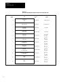
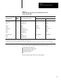
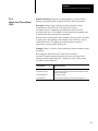
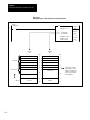
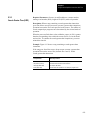
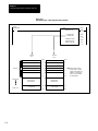
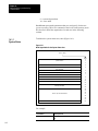
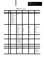
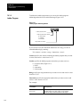
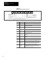
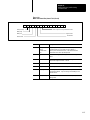
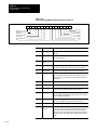
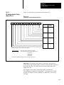
Chapter 14
Addressing Memory and Monitoring
Controller Status
9 = ASCII
10 = high order integer
12 = pointers
13 = status
File specifies the file number for the data table section and can be a value
from 0 to 999.
Important: The file level dos not apply for the timer, counter, and pointer
sections. If you are specifying one of these sections, enter 0 for the file.
Structure specifies the timer, counter, or pointer number and can be a
value from 0 to 9999.
Important: The structure level does not apply for the output image, input
image, integer, decimal, binary, ASCII, and status sections. if you are
specifying one of these sections, enter 0 for the structure.
Word specifies the word number for the data table section:
Section
Acceptable Word Numbers
output or imput image
0-77778
timers or counters
0 for the control word
1 for the preset word
2 for the accumulated value word
integer, floating point, decimal,
binary, ASCII, high order
integer, status
0-9999
pointers
0 for the section
1 for the file
2 for the word
Refer to section 14.2 for detailed information on status file organization.
For example:
This address
Corresponds to
E3.1.2.3.0.0
the data table area (E3), context (1), input image table (2),
file (3), word (0)
E3.1.8.1.0.5
binary file 1, word 5
E3.3.3.10.0
the control word (0) for timer 10 in context (3)
14-5