1
User’s Manual
LG Programmable Logic Controller
GLOFA GM6 Series
LG Industrial Systems
◎
CONTENTS
◎
Chapter 1. GENERAL
1.1 Guide to User’s Manual………………………………………………………………… 1 - 1
1.2 Features ……………………………………………………………………………… 1 - 2
1.3 Terminology …………………………………………………………………………… 1 - 3
Chapter 2. SYSTEM CONFIGURATION
2.1 Overall Configuration…………………………………………………………………… 2 - 1
2.2 Product List …………………………………………………………………………… 2 - 2
2.2.1 GM6 series Configuration ………………………………………………………… 2 - 2
2.3 System Configuration Types …………………………………………………………… 2 - 3
2.3.1 Basic System …………………………………………………………………… 2 - 3
2.3.2 Computer Link System…………………………………………………………… 2 - 3
2.3.3 Network System ………………………………………………………………… 2 - 4
Chapter 3. GENERAL SPECIFICATION
3.1 General Specifications ………………………………………………………………… 3 - 1
Chapter 4. CPU MODULE
4.1 Performance Specifications …………………………………………………………… 4 - 1
4.2 Operation processing ………………………………………………………………… 4 - 2
4.2.1 Operation processing Methods …………………………………………………… 4 - 2
4.2.2 Operation processing at momentary power failure occurrence …………………… 4 - 3
4.2.3 Scan Time ……………………………………………………………………… 4 - 4
4.2.4 Scan Watchdog Timer …………………………………………………………… 4 - 4
4.2.5 Timer processing ………………………………………………………………… 4 - 5
4.2.6 Counter processing ……………………………………………………………… 4 - 7
4.3 Program ……………………………………………………………………………… 4 - 9
4.3.1 Program Configuration …………………………………………………………… 4 - 9
4.3.2 Program Execution Procedures…………………………………………………… 4 - 10
4.3.3 Task……………………………………………………………………………… 4 - 13
4.3.4 Error Handling …………………………………………………………………… 4 - 19
4.3.5 Precautions when using special modules ………………………………………… 4 - 20
4.4 Operation Modes ……………………………………………………………………… 4 - 24
4.4.1 RUN mode ……………………………………………………………………… 4 - 24
4.4.2 STOP mode ……………………………………………………………………… 4 - 25
4.4.3 PAUSE mode …………………………………………………………………… 4 - 25
4.4.4 DEBUG mode …………………………………………………………………… 4 - 25
4.4.5 Operation Mode Change ………………………………………………………… 4 - 26
4.5 Functions ……………………………………………………………………………… 4 - 28
4.5.1 Restart mode …………………………………………………………………… 4 - 28
4.5.2 Self-diagnosis …………………………………………………………………… 4 - 30
4.5.3 Remote function ………………………………………………………………… 4 - 31
4.5.4 I/O Force On/Off function ………………………………………………………… 4 - 32
4.5.5 Direct I/O Operation function……………………………………………………… 4 - 33
4.5.6 External Device Error Diagnosis function ………………………………………… 4 - 33
4.6 Memory Configuration ………………………………………………………………… 4 - 36
4.7 I/O No. Allocation Method ……………………………………………………………… 4 - 38
4.8 Names of Parts………………………………………………………………………… 4 - 39
Chapter 5. BATTERY
5.1 Specifications ………………………………………………………………………… 5 - 1
5.2 Handling Instructions…………………………………………………………………… 5 - 1
5.3 Battery Replacement…………………………………………………………………… 5 - 1
Chapter. 6 USING THE USER PROGRAM IN FLASH MEMORY
6.1 Structure ……………………………………………………………………………… 6 - 1
6.3 Handling ……………………………………………………………………………… 6 - 1
Chapter. 7 DIGITAL INPUT AND OUTPUT MODULES
7.1 Notes on Selecting Input and Output Modules ………………………………………… 7 - 1
7.2 Digital Input Module Specifications……………………………………………………… 7 - 2
7.2.1 16-point 24VDC input module (source/sink type) ………………………………… 7 - 2
7.2.2 16-point 24VDC input module (source type) ……………………………………… 7 - 3
7.2.3 32-point 24VDC input module (source/sink type) ………………………………… 7 - 4
7.2.4 32-point 24VDC input module (source type) ……………………………………… 7 - 5
7.2.5 8-point 110VAC input module …………………………………………………… 7 - 6
7.2.6 8-point 220VAC input module …………………………………………………… 7 - 7
7.3 Digital Output Module Specifications …………………………………………………… 7 - 8
7.3.1 16-point relay output module……………………………………………………… 7 - 8
7.3.2 16-point transistor output module (sink type) ……………………………………… 7 - 9
7.3.3 32-point transistor output module (sink type) ……………………………………… 7 - 10
7.3.4 8-point triac output module ……………………………………………………… 7 - 11
Chapter 8. POWER SUPPLY MODULE
8.1 Selection of power supply module ……………………………………………………… 8 - 1
8.2 Specifications ………………………………………………………………………… 8 - 2
8.3 Names of Parts………………………………………………………………………… 8 - 3
Chapter 9. BASE BOARD
9.1 Specifications ………………………………………………………………………… 9 - 1
9.2 Names of Parts………………………………………………………………………… 9 - 1
Chapter 10. INSTALLATION AND WIRING
10.1 Installation …………………………………………………………………………… 10 - 1
10.1.1 Installation Environment ………………………………………………………… 10 - 1
10.1.2 Handling Instructions …………………………………………………………… 10 - 4
10.1.3 Module Loading and Unloading ………………………………………………… 10 - 7
10.2 Wiring………………………………………………………………………………… 10 - 9
10.2.1 Power Supply Wiring …………………………………………………………… 10 - 9
10.2.2 Input and Output Devices Wiring …………………………………………………10 - 11
10.2.3 Grounding ………………………………………………………………………10 - 11
10.2.4 Cable Specification for wiring ………………………………………………… 10 - 12
Chapter 11. MAINTENANCE
11.1 Maintenance and Inspection…………………………………………………………… 11- 1
11.2 Daily Inspection ……………………………………………………………………… 11- 1
11.3 Periodic Inspection …………………………………………………………………… 11- 2
Chapter 12. TROUBLESHOOTING
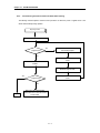
12.1 Basic Procedures of Troubleshooting ………………………………………………… 12- 1
12.2 Troubleshooting ……………………………………………………………………… 12- 1
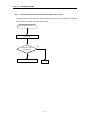
12.2.1 Troubleshooting flowchart used when the POWER LED turns OFF ……………… 12- 2
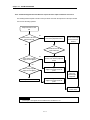
12.2.2 Troubleshooting flowchart used when the STOP LED is flickering………………… 12- 3
12.2.3 Troubleshooting flowchart used when the RUN and STOP LEDs turns off ………… 12- 4
12.2.4 Troubleshooting flowchart used when the output load of the
output module does not turns on ………………………………………………… 12 - 5
12.2.5 Troubleshooting flowchart used when a program
cannot be written to the CPU module …………………………………………… 12 - 6
12.3 Troubleshooting Questionnaire ……………………………………………………… 12 - 7
12.4 Troubleshooting Examples …………………………………………………………… 12 - 8
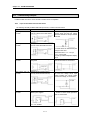
12.4.1 Input circuit troubles and corrective actions ……………………………………… 12 - 8
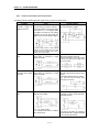
12.4.2 Output circuit troubles and corrective actions …………………………………… 12 - 9
12.5 Error Code List ………………………………………………………………………12 - 11
Chapter 13. Dedicated Cnet communication for GM6
13.1 Introduction…………………………………………………………………………… 13- 1
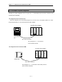
13.2 The example of system configuration ………………………………………………… 13- 2
13.3 The pin assignment of RS-232C connector of the GM6 dedicated Cnet communication … 13- 3
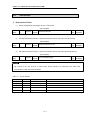
13.4 Frame structure ……………………………………………………………………… 13- 4
13.5 List of commands …………………………………………………………………… 13- 7
13.6 Data type …………………………………………………………………………… 13- 8
13.7 Execution of commands (Ex.) ………………………………………………………… 13- 9
13.8 Error code during NAK occurrence (for GM6 dedicated communication) ……………… 13- 29
APPENDICES
Appendix 1. System Definitions …………………………………………………………APP 1 - 1
Appendix 2. Flag List ……………………………………………………………………APP 2 - 1
Appendix 3. Function/Function Block List…………………………………………………APP 3 - 1
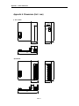
Appendix 4. Dimensions
………………………………………………………………APP 4 - 1
Chapter 2. SYSTEM CONFIGURATION
Chapter 2.
SYSTEM CONFIGURATION
The GLOFA-GM6 series has various modules suitable to configuration of the basic, computer link and network
systems.
This chapter describes the configuration and features of each system.
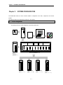
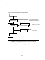
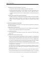
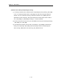
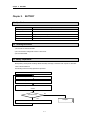
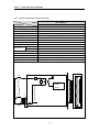
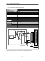
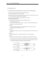
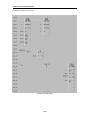
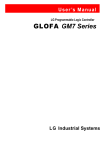
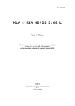
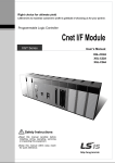
2.1 Overall Configuration
The following shows the overall configuration of the GLOFA-GM6 series.
RUN
STOP
GM6-CPUA
RUN
PAU/REM
GMW
STOP
IN
Battery
CPU Module
RS-232C
Cable
GMWIN
Discket
PO
GM6-PAFA
Power Supply
Module
(GM6-PAF□)
Base board(GM6-B0□M)
G6I-D22B
Input Module
(G6I-□□□□)
G6F-AD2A
G6I-RY2A
Output Module
(G6Q-□□□A)
2-1
Special Module
(G6F-□□□□)
G6L-FUEA
Communication
Module
(G6L-□□□□)
Chapter 2. SYSTEM CONFIGURATION
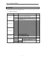
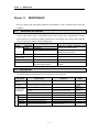
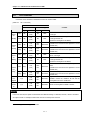
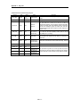
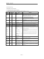
2.2 Product List
The following table shows product list of GLOFA-GM6 series.
2.2.1
GM6 series Configuration
Items
Models
GM6-CPUA
CPU module
GM6-CPUB
GM6-CPUC
Digital input module
Digital output module
Main base unit
Power supply module
G6I-D21A
G6I-D22A
G6I-D22B
G6I-D24A
G6I-D24B
G6I-A11A
G6I-A21A
G6Q-RY1A
G6Q-RY2A
G6Q-TR2A
G6Q-TR2B
G6Q-TR4A
G6Q-TR4B
G6Q-SS1A
GM6-B04M
GM6-B06M
GM6-B08M
GM6-PAFA
GM6-PAFB
GM6-PD3A
GM6-PDFA
Description
• Maximum I/O points: 256
• Special functions : RS-232 communication
• Maximum I/O points :
• Special functions : RS-422/485 communication, RTC, PID
• Maximum I/O points :
• Special functions : RS-232C communication, RTC, PID, HSC
• 8-point 12/24 VDC input module(current source & sink input)
• 16-point 12/24 VDC input module(current source & sink input)
• 16-point 12/24 VDC input module(current source input)
• 32-point 12/24 VDC input module(current source & sink input)
• 32-point 12/24 VDC input module(current source input)
• 8-point 110 VAC input module
• 8-point 220 VAC input module
• 8-point relay output module(2A)
• 16-point relay output module(2A)
• 16-point transistor output module(0.5A, sink output)
• 16-point transistor output module(0.5A, source output)
• 32-point transistor output module(0.1A, sink output)
• 32-point transistor output module(0.1A, source output)
• 8-point triac output module(1A)
• Up to 4 I/O modules can be mounted.
• Up to 6 I/O modules can be mounted.
• Up to 8 I/O modules can be mounted.
Free Voltage • 5 VDC : 2 A, 24 VDC : 0.3 A
(100 ~
• 5 VDC : 2 A
240VAC) • +15 VDC : 0.5 A, -15VDC : 0.2 A
DC24V
• 5 VDC : 2 A
DC12/24V
2-2
Remarks
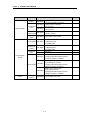
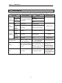
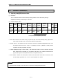
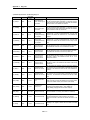
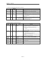
Chapter 2. SYSTEM CONFIGURATION
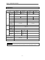
Items
Special modules
Models
Description
A/D conversion
module
• Voltage/current input : 4 channels
• DC -10 to 10V / DC -20 to 20 mA
• Voltage output : 4 channels
G6F-DA2V
• DC -10 to 10V
• Current output : 4 channels
G6F-DA1A
• DC 4 to 20 mA
• Counting range: 0 to 16,777,215(24 bit binary)
G6F-HSCA
• 50 kHz, 1 channel
D/A conversion
module
High speed
counter module
Positioning
module
G6F-AD2A
G6F-POPA • Pulse output, 2-axes control
• For Fnet I/F
G6L-FUEA • 1 Mbps base band
• For twisted cable
• For Fnet remote I/F
Fnet remote I/F
G6L-RBEA • 1 Mbps base band
module
• For twisted cable
Computer Link G6L-CUEB • RS-232C
module
G6L-CUEC • RS422
• Dnet I/F master module
G6L-DUEA • Complying with ODVA (Open Devicenet
Vendor Association) 2.0 standard.
• Dnet I/F slave input module
• 12/24 VDC input (16 points)
G6L-DSIA
Dnet I/F module
• Complying with ODVA (Open Devicenet
Vendor Association) 2.0 standard.
• Dnet I/F slave output module
• Relay output (16 points)
G6L-DSQA
• Complying with ODVA (Open Devicenet
Vendor Association) 2.0 standard.
Dust Proof
GM6-DMMA • Protect empty slot for dust
Module
Fnet I/F module
Communication
modules
Others
2-3
Remarks
Chapter 2. SYSTEM CONFIGURATION
2.3 System Configuration Types
System configuration is classified into 3 types that Basic system, Computer link system executing data
communications between the CPU module and a computer by use of a computer link module(G6L-CUEB/C) and
Network system controlling the PLC and remote I/O modules.
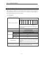
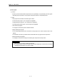
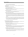
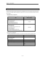
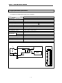
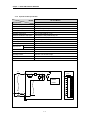
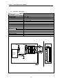
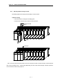
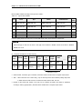
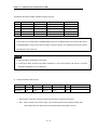
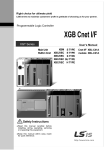
2.3.1
Basic System
The following describes basic system.
Slot number
CPU
POWER
0
1
2
3
4
5
6
7
0.0.0
0.1.0
0.2.0
0.3.0
0.4.0
0.5.0
0.6.0
0.7.0
~
~
~
~
~
~
~
~
0.0.15
0.1.15
0.2.15
0.3.15
0.4.15
0.5.15
0.6.15
0.7.15
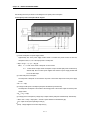
Example of System configuration
Base Board
(The above figure shows the configuration where 16-input/output
modules are loaded.)
Maximum number of Input/Output modules
8 modules
Maximum number of Input/Output points
• 16-point module mounted: 128 points
• 32-point module mounted: 256 points
CPU module
Power Supply module
Basic Base Unit
Configuration units
GM6-CPUA, GM6-CPUB, GM6-CPUC
I/O module
GM6-PAFA, GM6-PAFB, GM6-PD3A, GM6-PDFA
GM6-B04/06/08M
G6I-œœœœ
G6Q-œœœœ
Special module
G6F-œœœœ
Communication
module
G6L-œœœœ
I/O number allocation
64 points are allocated to each slot in a base board whatever it is empty or not.
There's no limitation for the location and the number of special modules on base board.
Special modules do not have fixed I/O numbers while a fixed I/O number is allocated to
a digital I/O module.
A dedicated function block controls a special module and memory is allocated
automatically.
• To use A/D, D/A conversion module, be sure to select GM6-PAFB power supply
Note for power supply module selection module that supplies ±15VDC instead of 24VDC. ±15VDC power is need for operation
of internal analog circuit of A/D and D/A conversion modules.
2-4
Chapter 2. SYSTEM CONFIGURATION
2.3.2
Computer Link System
Computer Link System communicates data between the CPU module and peripheral devices like a
computer or a printer by use of RS-232C and RS-422(or RS-485)interface of the computer link module.
The G6L-CUEB or G6L-CUEC are the computer link module for GM6 series. For details of computer link
module, refer to related User's Manual.
2.3.3
Network System
The Network system adapted in the GLOFA series a Fnet system that satisfies the IEC/ISA field bus
specifications. Fnet system as a network system is used for data communications between CPU modules
and control of remote I/O modules so that distribution of control and concentration of supervision could be
easy. For details, refer to Fnet system user's manual.
2-5
Chapter 3. GENERAL SPECIFICATIONS
Chapter 3. GENERAL SPECIFICATION
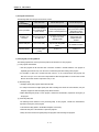
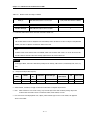
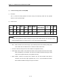
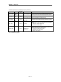
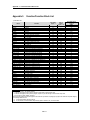
3.1 General specifications
The following shows the general specifications of the GLOFA-GM series.
No
1
2
3
4
5
6
7
8
9
10
11
Item
Operating ambient
temperature
Storage ambient
temperature
Operating ambient
humidity
Storage ambient
humidity
Vibration
Shocks
Noise Immunity
Operating
ambience
Altitude
Pollution
Cooling method
Specifications
References
0 ~ 55 °C
-25 ~ +75 °C
5 ~ 95%RH, non-condensing.
5 ~ 95%RH, non-condensing.
Occasional vibration
Acceleration
Amplitude
Sweep count
0.075 mm
9.8 m/s 2{1 G}
10 times per
Continuous vibration
axis,
Frequency
Acceleration
Amplitude
on X,Y, Z axis
0.035 mm
10≤f <57 Hz
2
4.9 m/s {0.5G}
57≤f≤150 Hz
Maximum shock acceleration: 147 m/s2{15G}
Duration time: 11 ms
Pulse wave: half sine pulse (3 shocks per axis, on X,Y,Z axis)
Square wave
± 1,500 V
Impulse Noise
Electronic
Voltage : 4 kV
discharge
Radiated
electromagnetic field
27 ~ 500 MHz, 10 V/m
noise
Digital I/O
Power
Digital I/O
(<24V)
Fast transient/burst
Item
supply
(>24V)
Analog I/O
noise
interface
Voltage
2 kV
1 kV
0.25 kV
Frequency
10≤ f<57 Hz
57≤f≤150 Hz
Free of corrosive gases and excessive dust.
IEC 1131-2
IEC 1131-2
IEC 1131-2,
IEC 801-3
IEC 1131-2,
IEC 801-3
IEC 1131-2,
IEC 801-4
IEC 1131-2
2,000 m or less
2
Air-cooling
REMARK
1) IEC(International Electromechanical Commission) : An international civilian institute who establishes
international standards in area of electric's and electronics.
2)Pollution : An indicator which indicates pollution degree which determine insulation performance of equipment.
Pollution 2 means that non-conductive pollution usually occurs but temporal conduction occurs with condensing
3-1
Chapter 4. CPU module
Chapter 4. CPU MODULE
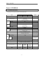
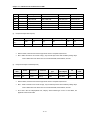
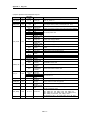
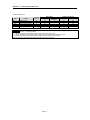
4.1 Performance specifications
The following shows the general specifications of the GLOFA-GM series.
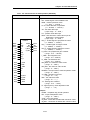
Items
Specifications
GM6-CPUB
GM6-CPUA
Operation method
Cyclic operation of stored program, Interrupt task operation
I/O control method
Scan synchronized batch processing method(Refresh method)
Programming language
Ladder Diagram(LD)
Instruction List(IL)
Sequential Function Chart(SFC)
Operator
Number of
instructions
Remarks
LD : 13, IL : 21
Basic function
194
Basic function block
11
Special function block
Each special module have their own special function blocks
Operator
Processing
speed
Basic function
Refer to Appendix 3.
Basic function block
Programming memory capacity
68 k bytes(17 k steps)
I/O points
256 points
Data memory
Direct variable area
2 to 8 k bytes
Symbolic variable area
30 k bytes – Direct variable area
Timer
No limitations in points.
Time range : 0.01 to 4294967.29 sec(1193 hours)
1 point occupies 20 bytes
of symbolic variable area.
Counter
No limitations in points
Counting range: -32768 to +32767
1 point occupies 8 bytes
of symbolic variable area.
Numbers of program blocks
Program
types
GM6-CPUC
100
Initialization programs
Task
Programs
1 (_INIT)
Time driven tasks
0~8
External interrupt tasks
0~8
Internal task
Total : 8
(The type of task is
variable, however, total
numbers of tasks is 8.)
0~8
Operation modes
RUN, STOP, PAUSE and DEBUG
Restart modes
Cold, Warm
Self-diagnostic functions
Watch dog timer, Memory error detection, I/O error detection, Battery
error detection, Power supply error detection, etc.
Data protection method at power failure
Set to 'Retain' variables at data declaration.
Built-in special functions
RS-232C
RS-422/485
RTC
PID control
Internal current consumption
170mA
210mA
RS-232C
RTC
PID control
High Speed Counter
170mA
Weight
0.11Kg
0.11 Kg
0.12Kg
4-1
Chapter 4. CPU module
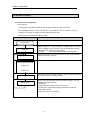
4.2 Operation Processing
4.2.1 Operation Processing Method
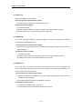
1) Cyclic operation
A PLC program is sequentially executed from the first step to the last step, which is called scan.
This sequential processing is called cyclic operation. Cyclic operation of the PLC continues as long as
conditions do not change for interrupt processing during program execution.
This processing is classified into the following stages.
Stages
Processing
Operation Start
-
Initialization
• Stage for the start of a scan processing. it is executed only one time when
the power is applied or reset is executed. It executes the following processing.
4I/O modules reset 4Execution of self-diagnosis
4Data clear
4I/O module address allocation or type registration
Input image area refresh
Program operation processing
• Input module conditions are read and stored into the input image area before
operation processing of a program.
• Program is sequentially executed from the first step to the last step
Program start
~
Program end
Output image area refresh
END processing
• The contents stored in the output image area is output to output modules when
operation processing of a program is finished.
• Stage for return processing after the CPU module has finished 1 scan. The
following processing are executed.
4Self-diagnosis
4Change of the present values of timer and counter, etc.
4Processing data communications between computer link module and
communications module.
4Checking the switch for mode setting.
4-2
Chapter 4. CPU module
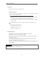
2) Time driven interrupt operation method
In time driven interrupt operation method, operations are processed not repeatedly but at every pre-set interval.
Interval, in the GM6 CPU module, can be set to between 0.01 to 4294967.29 sec. This operation is used to
process operation with a constant cycle.
3) Event driven interrupt operation method
If a situation occurs which is requested to be urgently processed during execution of a PLC program, this
operation method processes immediately the operation which corresponds to interrupt program. The signal
which informs the CPU module of those urgent conditions is called interrupt signal. The GM6 CPU module has
two kind of interrupt operation methods, which are internal and external interrupt signal methods.
4.2.2
Operation processing at momentary power failure occurrence
The CPU module detects any momentary power failure when the input line voltage to the power supply
module falls down below the defined value.
When the CPU module detects any momentary power failure, the following operations will be executed.
1) Momentary power failure within 20 ms
(1) The operation processing is stopped with the output retained.
(2) The operation processing is resumed when normal status is restored.
(3) The output voltage of the power supply module retains the defined value.
(4) The watch dog timer(WDT) keeps timing and interrupt timing normally
while the operations is at a stop.
2) Momentary power failure exceeding 20 ms
• The re-start processing is executed as the power is applied.
REMARK
1) Momentary power failure
The PLC defining power failure is a state that the voltage of power has been lowered outside the allowable variation
range of it. The momentary power failure is a power failure of short interval(several to tens ms).
4-3
Chapter 4. CPU module
4.2.3 Scan Time
The processing time from a 0 step to the next0 step is called scan time.
1) Expression for scan time
Scan time is the addition value of the processing time of scan program that the user has written, of the task program
processing time and the PLC internal processing time.
(1) Scan time = Scan program processing time + Task program processing time + PLC internal processing time
• Scan program processing time = The processing time used to process a user program that is not specified to a task program.
• Task program processing time = Total of the processing times of task programs executed during one scan.
• PLC internal processing time = Self-diagnosis time + I/O refresh time + Internal data processing time + Communications
service processing time
(2) Scan time differs in accordance with the execution or non-execution of task programs and communications processing, etc.
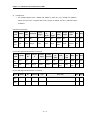
2) Flag
(1) Scan time is stored in the following system flag area.
• _SCAN_MAX : Maximum scan time (unit : 1 ms)
• _SCAN_MIN : Minimum scan time (unit : 1 ms)
• _SCAN_CUR : Current scan time (unit : 1 ms)
4.2.4 Scan Watchdog Timer
1) Watchdog timer is used to detect a delay of abnormal operation of sequence program.
(Watchdog time is set in menu of basic parameter of GMWIN.)
2) When watchdog timer detects an exceeding of preset watchdog time, the operation of PLC is stopped
Immediately and all output is off.
3) If an exceeding of preset watchdog time is expected in sequence program, use ‘WDT_RST’ function.
‘WDT_RST’ function make elapsed watchdog time as zero.
4) In order to clear watchdog error, using manual reset switch, restarting the PLC and mode change to STOP
mode are available.
REMARK
Setting range of watchdog : 1 ~ 65,535ms( 1ms base )
4-4
Chapter 4. CPU module
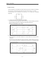
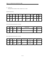
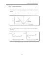
4.2.5 Timer Processing
The CPU module timer is on incremental timer which increase its present value according to the measuring
time. Three types of On Delay Timer(TON), Off Delay Timer(TOF) and Pulse Timer(TP) are available.
Its measuring range is 0.001 to 4,294,967,295 sec (1,193 hours) by 1 ms. For details, refer to ‘GLOFA-GM
Programming’.
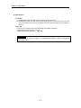
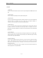
1)
On Delay Timer Process Time Change and Contact On/Off)
Timer Process time is newly changed when the timer function block is executed. When the process time
reaches the setting time (process time = setting time), the Timer output contact turns on.
On Delay Timer Timing Diagram is shown as below.
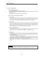
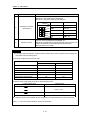
2)
Off Delay Timer Process Time Change and Contact On/Off
• If input condition turns on, timer output contact(Q) turns on. If input condition turns off, timer process time
change starts.
• The process time is newly changed when the timer function block is executed. When the process time
reaches the setting time (process time = setting time), the contact (Q) turns off. The following diagram
shows Off Delay Timer Timing.
4-5
Chapter 4. CPU module
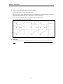
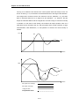
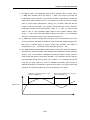
3)
Pulse Timer Process Time Change and Contact On/Off
If input condition turns on, output contact (Q) turns on.
The process time is newly changed when the timer function block is executed. When the process time
reaches the setting time (process time = setting time), the contact (Q) turns off.
The contact turns off after the setting time regardless of input condition off status.
The following diagram shows pulse timer timing.
4)
Timer error
The maximum timer error is ‘1 scan time + time from the start of scan to execution of the timer function
block".
4-6
Chapter 4. CPU module
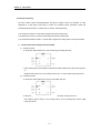
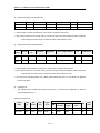
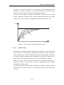
4.2.6 Counter Processing
The CPU module counter increment/decrement the present counting value by the detection of rising
edge(offàon) of input signal. Three types of counter are increment counter, Decrement counter and
Increment-Decrement Counter. For details, refer to ‘GLOFA – GM Programming’.
• The Increment counter is a counter which increment the present counting value
• The Decrement counter is a counter which decrement the present counting value
• The Increment-Decrement counter is a counter which compares the counting values of two input conditions.
1)
Counter Present Value Change and Contact On/Off
(1) Increment Counter
• It should have Input condition (CU), reset condition (R) and setting value (PV).
PV
• If the counting value (CV) increments and reaches the setting value(PV) the output contact (Q) turns
on.
When the reset signal is turn on, the counting value is set to ‘0’ and the output contact (Q) turns off.
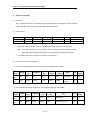
(2) Decrement Counter
• It should have input condition (CD), load (LD) and setting value (PV).
CD
LD
• If the counting value (CV) decrements and reaches ‘0’, the output contact (Q) turns on.
If the load(LD) signal is turned on, the counting value is set to the setting value and the output
contact (Q) turns off.
4-7
Chapter 4. CPU module
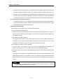
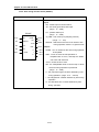
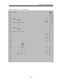
(3) Increment/Decrement Counter
• It should have Increment input condition (CU), Decrement input condition (CD), load (LD) and
setting value (PV).
NAME
CTUD
BOOL
▶CU
QU
BOOL
BOOL
▶CD
QD
BOOL
BOOL
R
BOOL
LD
INT
PV
CV
INT
• If reset signal(R) turns on, counting value (CV) is set to ‘0’.
• If load signal(LD) turns on, counting value is set to setting value(PV).
• It is increased by 1at the rising edge of increment input(CU) and decreased by 1 at the edge of
decrement input(CD). If counting value(CV) is equal or larger than setting value(PV),QU will be on,
and if counting value(CV) is equal or less than setting value(PV),QD will be on.
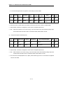
2)
Counting speed
• The counting speed is decided by scan time and it will be counted when on time or off time of input
condition is larger than each scan time.
Max. Counting speed (Cmax.) = n / 100 × 1 / ts
[pps]
[ n : Duty(%), ts : scan time(s) ]
• Duty is percent of on time / off time.
on
off
T1
T2
T1 ≤ T2 : n = T1 / (T1+T2) × 100 [%]
T1 > T2 : n = T2 / (T1+T2) × 100 [%]
4-8
Chapter 4. CPU module
4.3 Program
4.3.1 Program Configuration
A program consists of all of the function elements that is needed to execute a particular control. It is to be
stored in the internal RAM of the CPU module or the flash memory of the memory module.
The function elements are classified as below.
Function
Elements
Processing Operation
Initialization
program
• Executed when the power is applied or the CPU operation is transited to the RUN
mode.
• Executes the initial/fixes data setting for execution of scan program and the
initialization of peripheral devices on special modules.
Scan program
• Processes the constantly repeated signals which are executed every scan.
Time driven task
program
• When the following time conditional processing is required the program is executed
complying with the time interval setting.
4In case that the processing need a shorter interval than that of average one scan
processing time.
4In case that the processing need a longer interval than that of average one scan
processing time.
4In case that the processing should be executed by the specified time interval.
Event driven task
program
• A shorter processing is executed for internal or external interrupt.
4-9
Chapter 4. CPU module
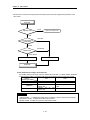
4.3.2 Program Execution Procedure
The followings explain the program execution procedure when the power is applied or the mode setting switch
of CPU module is in the RUN status.
Program operation processing is executed as the procedure given below
Operation start
• Executed when the power has been applied
or the CPU operation is in the Run mode
Initialization program
• Restart operation is executed complying with
the initialization task(_INIT, HINIT)
*1
External task program
Scan program
Time driven task program
Executed only when the condition
has been satisfied.
Executed only when the condition
Internal task program
has been satisfied.
END processing
REMARK
1) *1 : In the GLOFA PLC, the time driven interrupt task programs and event driven interrupt task
programs are called task program.
Event driven programs are classified into single task(internal interrupt) or interrupt task (external
interrupt) according to the S/W and H/W interrupt signaling method.
4 - 10
Chapter 4. CPU module
1) Initialization program
(1) Function
• The Initialization program initializes the program to execute scan and task programs.
• The initialization can be executed with the restart mode which has been specified for program.
(2) Restart mode execution conditions
• The initialization tasks can be specified as below complying with the purpose of the initialization task.
4 Program for Cold/ Worm restart started by the _INIT task
(3) Cold/ Warm Restart program
• The initialization program specified to _INIT task is executed with cold or warm restart mode when the
operation starts.
• This initialization program executes the operations repeatedly until the setting conditions are
satisfied(that is, until the Flag_INIT_DONE in the initialization program turns on). However, the I/O
refresh is still executed.
(4) Flag
• _INIT_RUN flag is on during executing the initialization program.
2) Scan program
(1) Function
• In order to process signals which repeats constantly, the program executes its sequential operation
repeatedly from the first step to the end step.
• If the interrupt task execution condition has been satisfied by a time driven task or event driven task
module during scan program execution, the program that is under execution will be temporary stopped
and the corresponding task program will be executed.
• If the scan program has been completely executed, the single task(internal interrupt) execution condition
will be checked and the corresponding task program will be executed.
(2) configuration
• Up to 100 scan programs can be used.
(If task programs are used, the usable number is reduced as many as that of the used task programs)
• Program has been not specified to initialization or task program when writing that program, it will be
automatically specified to scan program.
• Scan program has lowest execution priority and the priorities of scan program are determined their
registration sequence in the GMWIN screen when writing those programs.
4 - 11
Chapter 4. CPU module
3) Task program
(1) Function
• In order to process internal/ external signal which occurs periodically or non-periodically, the task program
temporarily stop the operation of scan program and processes first the corresponding function
(2) Types
• Task programs are classified into the three types as below.
4 Time driven task program : Up to 8 programs are applicable
4 Single (internal) task program : Up to 8 programs are applicable
4 Interrupt (external) task program : Up to 8 programs are applicable
• Time driven task program
4 The program is executed by the time internal set before
• Single (internal) task program
4 The corresponding program will be executed at the rising edge and on state of internal contact in the
program.
4 The detection of the start up condition will be executed after the scan program has been processed.
• Interrupt (external) task program
4 The program is executed according to the external signal a input to the interrupt module
REMARK
1) Refer to section 4.3.3 task for details of task program.
2) For interrupt signal processing, the GM6 series use general digital input module instead of external
interrupt input module. Refer 4.3.3. task for details.
4 - 12
Chapter 4. CPU module
4.3.3 Task
The followings explain the program structure and tasks of the GMWIN, that is, the GLOFA-GM programming
S/W, in order to give an understanding of the task function
Program 1
Task 1
Program Block
( program 1)
Program 2
Function
Program 3
Program Block
Program 4
Task 2
Function Block
*1
( program 3)
Program 5
Program Block
Task 3
( program 7)
Program 6
Function
Program 1
Program Block
REMARK
1) A task executes the some function as the control panel
which are used to execute programs. Each task consists
of one or more program blocks in the three types of
program. Those programs are called task programs A
program to which a task has not been specified as
marked with '*1' will be automatically specified to scan
program
4 - 13
Chapter 4. CPU module
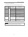
1) Task types and functions
The following table show the types and functions of tasks
Type
Time driven task
External interrupt task
Internal interrupt task
8
8
Start up condition
Time driven interrupt
(up to 4,294,967.29sec
by the 10msec)
At the rising edge of input
contact on the designated slot
Detection and
execution
Executed periodically
as setting time
Immediately executed when
an edge occurs in the
interrupt module
Detection delay time
Up to 1msec delay
Execution priority
Level 0 to 7
(Level 0 has highest
priority)
Maximum 1msec delay +
Input module delay(Within
3msec
8
The rising edge or on
state of the BOOL variable
data which has been
specified of buffer data
Executed with edge
detection after scan
program has been
finished
Specifications
Number 1)
Delayed for the same time
as maximum scan time
Level 0 to 7
Level 0 to 7
* 1) Up to 8 task programs are available.
2) Task program processing Method
The following explains the common processing method and instructions for task programs
(1) Task program characteristics
• The task program will be executed when a execution condition is satisfied while the scan program is
repeatedly processed at every scan. Be sure to consider that point when writing a task program
• For example, if a timer and a counter have been used in a 10 sec cycle time driven task program, the
timer can occur up to 10 sec error and an input which has been changed within 10 sec will not be counted
because the counter checks its input status every 10 sec
(2) Execution priority
• The higher priority task program will be executed firstly.
• If a newly invoked task has higher priority than that of existing tasks which are under execution, they are
temporary stopped and task has higher priority will be executed.
• When determining the priority of a task program, consider the characteristics, importance and urgency of
the program
(3) Processing delay time
The following factors influence on the processing delay of task program, consider the characteristics,
importance and urgency of the program
• Task detection delay (Refer to the detailed description of each task)
• Execution delay due to the execution of prior task programs
• Delay due to the execution of higher priority task programs while executing task programs
4 - 14
Chapter 4. CPU module
(4) Relationship of task program to initialization or scan program
• User defined tasks will not start while the initialization task program is being executed.
• As scan program has the lowest priority, if a task is invoked the scan program will be stopped and the
task programs will be processed prior to them. Therefore, if tasks are invoked many times or
concentrated sometimes the scan time may be extended abnormally. Be cautious when setting task
conditions.
(5) Protection of the programs under execution from task programs
• If problems can be occur in case that program lose its execution continuousness by the task programs
which have higher proprieties, the execution of task programs can be partly perverted For program
protection, use the DI function(Task program start-up disable) or EI function(task program start-up
enable)
3) Time driven task program processing method
The followings explain the processing method of a task program when its task condition(start-up condition) has
been set to be driven by time.
(1) Settings that have to be set for the task
• Set the task execution cycle and its priority which are used as start-up conditions for the task programs to
be executed. Priority number will be assigned as task number automatically.
(2) Time driven task processing
• The corresponding time driven interrupt task program will be executed every setting time internal
(execution cycle).
(3) Precautions for using the time driven task program
• While a time driven task program is being executed or ready for its execution, if a same priority task
program has been invoked to be executed the newly invoked task will be ignored, the representative task
collision warning flag (_TASK_ERR) will be set to ON, the detailed system error flag(_TC_BMAP[n] will be
set to ON at its corresponding location and occurrence time of the time driven tasks whose execution
requests have been ignored will be written at its corresponding location of the flag _TC_CNT[n].
• The timer that invokes the execution request for time driven task programs will be incremented only when
the operation mode is in the RUN mode
If the RUN mode has been changed into the PAUSE mode while operating with the RUN mode, and then
the operation mode has been changed again into the RUN mode, the operation time spent with the
PAUSE mode will be ignored.
• When setting the execution cycle for a time driven task program, be cautious that execution requests for
many time driven task programs can occur. If four time driven task programs of cycle 2, 4, 10 and 20sec
are used, four execution requests will occur every 20 sec and scan time can be momentarily extended.
4 - 15
Chapter 4. CPU module
4) External contact program processing method
The following explains in the case that the task( start-up condition) of a task program has been set to an
external input signal.
(1) Settings that have to be set for the input module
• A contact of input module can be used as interrupt input.
(2) Settings that have to be set for the task
• Set the contact No. of input module and priority for the task that will be used as start-up conditions of the
task programs to be executed. Priority will be the task number.
(3) External contact task processing
• The CPU module checks the occurrence of interrupt input every 1ms and executes the task program
which are designated by the contact at which the signal has been occurred.
(4) Precautions for using an external contact task.
• While a task program which are designated by an input module having interrupt input, contact is being
executed or ready for its execution, if an execution request of a task program has been occurred to the
same input contact then the newly invoked task will be ignored, the representative task collision warning
flag(_TASK_ERR) will be set to ON, the detailed system error flag(_TC_BAMP[n]) will be set to ON at its
corresponding location and the occurrence time of the external task whose execution request has been
congested.
• Execution request for a task program can be accepted only when the operation mode is in the RUN
mode. That is, if the RUN mode has been changed into the PAUSE mode while operating with the RUN
mode and the operation mode has been changed into the RUN mode again, all execution requests
occurred during the operation with the PAUSE mode will be ignored.
5) Internal task program processing method
The following explains the processing method when the task (start-up condition) of a task program has been
set to the contact of direct variable area(I, Q or M) or automatic variable area.
(1) Settings that have to be set for the task.
• Set the contact No. of input module and priority for the task that will be used as start-up conditions of the
task programs to be executed. Priority will be the task number.
(2) Internal contact task processing
• After the execution of scan program has been completed in the CPU module, the internal contacts that
are the start-up conditions of the task program will be checked and the internal task programs where
rising edge or on state has been occurred will be executed in accordance with its parameter.
(3) Precautions when using an internal task program.
• The internal task program is executed when scan program has finished its execution. Therefore, though
the execution condition for the internal task program has been invoked in the scan program or task
program(time driven, external) the task (start-up condition) will not be immediately executed but will be
executed when scan program has finished its execution.
4 - 16
Chapter 4. CPU module
• If execution of an internal task program is requested, the execution conditions will be checked when scan
program has finished its execution. Therefore, if an internal task execution conditions, during ‘one’ scan,
has been occurred and disappeared (if the specified contact has been turned from OFF to ON, and then
from ON to OFF) by scan program or (time driven or external) task program the task will not be executed
as the execution condition can not be detected at the time that execution conditions are being checked.
6) Task processing at momentary power failure
• In case of the power failure of 20 ms or less, the ready tasks before the power failure will be executed, a
time driven task will be invoked with calculation of the power failure time, and time driven tasks invoked
repeatedly before the power failure will be ignored.
7) Examination on task program
After writing down a task program, be sure to examine the following items.
(1) Task setting has been correctly done?
If tasks are invoked more frequently than necessary or several tasks are invoked simultaneously within one
scan, the scan time become longer and irregular. In case that the task setting cannot be changed, check
the maximum scan time.
(2) Task priorities are properly arranged?
The lower priority tasks still may not be processed after its time due to delay by higher priority tasks. In
some cases, if the prior tasks have been delayed and next task occurs task collision can occur. Set the
priority with due consideration of items such as urgency and execution time of a task.
(3) Task programs are written as shortly as possible?
If execution time of a task program is long, the scan time may become longer and irregular and also
collision of task programs may occur. Therefore, write task programs as shortly as possible.
(4) Protection of lower priority programs against higher priority program isn’t needed during execution of those
programs.
If the priority of a task program (or a scan program) has been set to lower priority and other tasks must not
interrupt during its execution, use the function ‘DI’ and ‘EI’ to protect the program partly. When processing
global variables used commonly in other programs, special modules or communications modules, problems
can occur.
REMARK
1) For examination on processing speed of scan program and task program, refer to the ‘Scan time
Calculation Example in the Section 4.2.3 ‘Scan Time’.
4 - 17
Chapter 4. CPU module
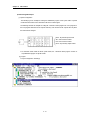
8) Example of program configuration and processing
When the task and program have been registered as below,
• Task registration : T_SLOW (interval : T#10ms, priority : = 0)
PROC_1 (single : %MX0, priority : = 3)
E_INT1 (interrupt : %IX0.0.1, priority : = 0)
• program registration : program → P0
program → P1 with the task T_SLOW
program → P2 with the task PROC_1
program → P3 with the task E_INT1
If program execution time is equal to external interrupt occurrence time :
• Execution time for each program : P0 = 17 ms, P1 = 2 ms, P2 = 7 ms, P3 = 2 ms
• Interrupt E_INT occurrence time : Occurred at the 6, 7, 20 ms after the operation started.
• PROC_1 : Invoked during execution of scan program
Program execution is shown as below.
• Processing with time
0 [ms] : Scan starts and the scan program P0 starts its execution.
0 to 6 [ms] : The program P0 is being executed.
6 to 8 [ms] : Execution request for P3 is input, and P0 is stopped and P3 is executed. Execution request for
P1 by E_INT1 at the 7 [ms] is ignored as the P2 is being executed.
8 to 10 [ms] : P3 finishes its execution and the P0 stopped continues its execution.
10 to 12 [ms] : P0 is stopped and P1 is executed due to execution request for P1.
12 to 20 [ms] : P2 finishes its execution and the P0 stopped continues its execution.
20 [ms] : Execution requests for P1 and P3 are simultaneously exist, but the higher priority P1 is executed
and P3 is ready for its execution.
20 to 22 [ms] : P0 is stopped and P1 is executed.
22 to 24 [ms] : P1 finishes its execution and the higher priority P3 is executed before P0.
24 to 25 [ms] : P3 finishes its execution and the P0 stopped completes its execution.
25 [ms] : Execution request for P2 is checked at the finish time of the scan program (P0) and P2 is executed.
25 to 30 [ms] : The program P2 is executed.
30 to 32 [ms] : Execution request for P1 is input and P2 is stopped and P1 finishes its execution.
32 to 34 [ms] : P1 finishes its execution and the P2 stopped finishes its execution.
34 [ms] : A new scan starts. (P0 starts its execution.)
4 - 18
Chapter 4. CPU module
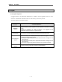
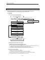
4.3.4 Error Handling
1) Error Classification
Errors occur due to various causes such as PLC system defect, system configuration fault or abnormal
operation result. Errors are classified into fatal error mode, which stops system operation for system
stability, and ordinary error mode, which continues system operation with informing the user of its error
warning.
The main factors that occurs the PLC system error are given as followings.
• PLC hardware defect
• System configuration error
•Operation error during execution of the user programs
• External device malfunction
2) Operation mode at error occurrence
In case of error occurrence, the PLC system write the error contents the corresponding flags and stops or
continues its operation complying with its operation mode.
(1) PLC hardware defect
The system enters into the STOP state if a fatal error such as the CPU module defect has occurred,
and continues its operation if an ordinary error such as battery error has occurred.
(2) System configuration error
This error occurs when the PLC hardware configuration differs from the configuration defined in the
software. The system enter into the STOP state.
(3) Operation error during execution of the user programs
If the numeric operation error of these errors occurs during execution of the user programs, its
contents are marked on the error flags and the system continues its operation. If operation time
overruns the watch dog time or I/O modules loaded are not normally controlled, the system enters into
the STOP state.
(4) External device malfunction
The PLC user program detects malfunctions of external devices. If a fatal error is detected the system
enters into the STOP state, and if an ordinary error is detected the system continues its operation.
REMARK
1) In occurrence of a fatal error the state is to be stored in the representative system error flags,
and an ordinary error in the representative system warning flags.
2) For details of flags, refer to Appendix 2. Flag List.
4 - 19
Chapter 4. CPU module
4.3.5 Precautions when using special modules
This system offers convenience and high performance in using special modules compared with the existing
methods. Therefore, take some precautions when composing the system. Check the system after the
following items have been thoroughly understood.
1) Special module programming
(1) Special function block is offered for each special module to make programs concise and to prevent
errors in writing down the user program.
(2) Function blocks are largely of two types. ‘Initialization’ function block for initializing special modules and
‘control’ function block for control of the operations of special modules. Function block functions as an
interface between the user program data and the special modules. As it includes the function that
watches the operation status of special modules and indicates the error status, other separate error
detection program does not have to be written.
(For detailed description of function block, refer to the User’s Manuals of special modules and GLOFAGM instructions.)
2) Special Module Initialization
This means to define the operations of a special module. It is done with ‘initialization’ function block.
Generally, it specifies the data range to used channel, resolution or filtering method, etc. It defines the
hardware characteristics and only one time execution at system start is sufficient.
REMARK
1) As the initialization should be finished before the scan program starts its execution, its program
should be written in the restart program (initialization task program).
3) Control of special modules
In control the operations of special modules, write the program using function blocks which correspond to
the operations that have to be controlled. These function blocks can locate at any place within the program.
REMARK
1) If a power failure occurs in the base unit where special units are loaded, special modules data are
removed. Therefore, data should be newly written down in the program.
4 - 20
Chapter 4. CPU module
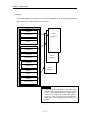
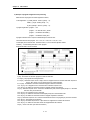
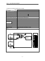
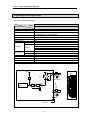
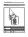
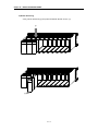
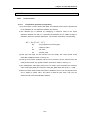
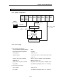
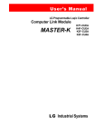
4) Restart Program Example
(1) System Configuration
The followings give an example for writing the initialization program of the system where a special
module has been loaded onto its basic base unit shown as below figure.
The followings describe an example for writing the ‘cold/warm restart program’ and ‘scan program’ for
the scan program where the ‘D/A 02’ outputs data every scan and the ‘D/A 03’ outputs data only when
the data has been changed.
P
O
W
E
R
DC32 : 32-point DC input module
A/D : A/D conversion module
D/A : D/A conversion module
RY32 : 32-point relay output module
• As cold/warm restart makes the whole system restart, the ‘cold/warm restart program’ consists of
only initialization program of special module.
(2) program
• Project Configuration : Restart.prj
4 - 21
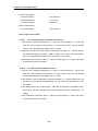
Chapter 4. CPU module
• Program : cw_rst.src (cold/warm restart initialization program)
Variable Name
INI_START
AD2INI.ACT
AD01_DT
AD01_CH
AD2INI
AD2INI.STAT
AD01_FE
AVG_NUM
Variable
type
VAR
VAR
VAR
VAR
VAR
VAR
VAR
VAR
Data type
BOOL
ARRAY[4] OF BOOL
ARRAY[4] OF BOOL
ARRAY[4] OF BOOL
FB Instance
USINT
ARRAY[4] OF BOOL
ARRAY[4] OF BOOL
Initial value
Set by parameter
Set by parameter
Set by parameter
4 - 22
Description
Start condition of initialization
Shows active channel
Select digital output type
Select channel to be used
Shows error status
Enable/Disable average function
Chapter 4. CPU module
• Program : scan.src (scan program)
STAT
Variable Name
READ
AD_CH
READ.DONE
READ.STAT
READ.ACT
READ.DATA
WRITE_1
DA01_DT
WRITE_1.DONE
WRITE_1.STAT
WRITE_2
DA02_DT
WRITE_2.DONE
WRITE_2.STAT
Variable
type
VAR
VAR
VAR
VAR
VAR
VAR
VAR
VAR
VAR
VAR
VAR
VAR
VAR
VAR
Data type
FB Instance
ARRAY[4] OF BOOL
ARRAY[4] OF BOOL
USINT
ARRAY[4] OF BOOL
ARRAY[4] OF INT
FB Instance
ARRAY[4] OF INT
BOOL
USINT
FB Instance
ARRAY[4] OF INT
BOOL
USINT
4 - 23
Description
Assign a channel of AD module to be used
Indicates the reading operation is completed
Shows the error status of AD read FB
Shows the error status of AD read FB
Digital data converted from analog input
Digital data to be output
Indicates the write operation is completed
Shows the error status of DA write FB
Digital data to be output
Indicates the write operation is completed
Shows the error status of DA write FB
Chapter 4. CPU module
4.4 Operation Modes
The CPU module operates in one of the four modes - the RUN, STOP, PAUSE and DEBUG mode.
The following describes the PLC operation processing in each operation mode.
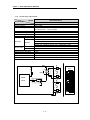
4.4.1 RUN mode
In this mode, programs are normally operated.
The first scan start in the RUN mode
If the operation mode is the RUN mode
when the power is applied
Mode condition at the start
If the operation mode has been changed
from the STOP mode to the RUN mode
Data area initialization complying with the restart mode
Data area initialization complying with the restart
mode set
Check on the effectiveness of the program and decision
on the possibility of the execution
Execution of input refresh
Execution of programs and task programs
Check on the normal operation of the loaded modules
and their mounting conditions
Processing the communications service or other
internal operations
Execution of output refresh
The RUN mode is maintained
Is the operation mode changed?
Changed into another mode
Operation with the operation mode changed
1) Processing when the operation mode changes.
Initialization of data area is executed when the first scan starts.
(1) If the PLC is in the RUN mode when applying the power :
(2) If the operation mode has been changed into from the STOP mode into the RUN mode : the
initialization is executed complying with the restart mode set. (cold / warm)
(3) The possibility of execution of the program is decided with check on its effectiveness.
2) Operation processing contents
I/O refresh and program operation are executed.
(1) Task programs are executed with the detection of their start-up conditions.
(2) Normal or abnormal operation and mounting conditions of the loaded module are checked.
(3) Communications service or other internal operations are processed.
4 - 24
Chapter 4. CPU module
4.4.2 STOP mode
In this mode, programs are not operated.
1) Processing when the operation mode changes
The output image area is cleared and output refresh is executed.
2) Operation processing contents
(1) I/O refresh is executed.
(2) Normal or abnormal operation and mounting conditions of the loaded module are checked.
(3) Communications service or other internal operations are processed.
4.4.3 PAUSE mode
In this mode, the program operation is temporarily stopped. If it returns to the RUN mode, the operation
continues from the state before the stop.
1) Processing when the operation mode changes
Data area clear and input image clear are not executed and the operating conditions just before the mode
change is maintain.
2) Operation processing contents
(1) I/O refresh is executed.
(2) Normal or abnormal operation and mounting conditions of the loaded module are checked.
(3) Communications service or other internal operations are processed.
4.4.4 DEBUG mode
In this mode, errors of a program are searched and the operation sequence is traced. Changing into this
mode is only possible in the STOP mode. In this mode, a program can be checked with examination on its
execution state and contents of each data.
1) Processing when the operation mode changes
(1) Data area is initialized at the starting time of the mode change complying with the restart mode, which
has been set on the parameters.
(2) The output image area is cleared and output refresh is executed.
2) Operation processing contents
(1) I/O refresh is executed by one time every scan.
(2) Communications service or other internal operations are processed.
4 - 25
Chapter 4. CPU module
3) Debug operation conditions
• Two or more of the following four operation conditions can be simultaneously specified.
Operation conditions
Description
Executed by the one
operation unit, (step over)
Executed to the specified
breakpoint.
If an operation command is ordered, the system operates one operation unit
and stops.
• If break step is specified in the program, the operation stops at those step
before execution.
• Up to 8 breakpoints can be specified.
If the contact area to be watched and the condition (Read, Write, Value)
where the operation has to stop are specified, the operation stops when the
specified operation occurs at the specified contact.(after execution)
If the number of scan that will be operated is specified, the operation stops
after it has operated by the specified scan number.
Executed according to
the contact state
Executed by the specified
scan number.
4) Operation method
(1) Execute the operation after the debug operation conditions have been set in the GMWIN.
(2) In task programs, each task can be specified to operation enable/disable.(For detailed operation
method, refer to the GMWIN User’s Manual Chapter 9.
4.4.5 Operation mode change
1) Operation mode change methods
The following method are used to change the operation mode.
(1) Change by the mode setting switch of CPU module.
(2) Change by the GMWIN connected with the CPU module communications port.
(3) Change by the GMWIN connected to the remote CPU module through Fnet.
(4) Change by the user’s command using FAM or computer link module, etc.
(5) Change by the ‘STOP function’, ‘ESTOP function’ during program execution.
2) Operation mode change by the mode setting switch of CPU module
The following shows the operation mode change by the mode setting switch of CPU module.
Mode setting switch position
RUN
STOP
STOP → PAU/REM
PAU/REM → RUN
RUN → PAU/REM
PAU/REM → STOP
Operation mode
Local RUN
Local STOP
Remote STOP
Local RUN
Local PAUSE / Remote RUN
Local STOP
1)
2)
REMARK
1) If the operation mode changes from RUN mode to local RUN mode by the mode setting switch, the
PLC operates continuously without stop.
2) If Local PAUSE disable(or Local PAUSE enable) is set by parameter in GMWIN, it operated as
Remote RUN(or Local PAUSE).
4 - 26
Chapter 4. CPU module
3) Remote operation mode change
Remote operation mode change is available only when the operation mode is set to the remote STOP
mode (i.e., the mode setting switch position is in the ‘STOP →PAU/REM’).
Mode
setting
switch
position
PAU/REM
Mode Change
Remote STOP → Remote RUN
Remote STOP → Remote PAUSE
Remote STOP → DEBUG
Remote RUN → Remote PAUSE
Remote RUN → Remote STOP
Remote RUN → DEBUG
Remote PAUSE → Remote RUN
Remote PAUSE → Remote STOP
Remote PAUSE → Remote DEBUG
DEBUG → Remote STOP
DEBUG → Remote RUN
DEBUG → Remote PAUSE
Mode change by
the GMWIN
Mode change using FAM
or computer link, etc.
m
m
×
m
m
m
×
m
m
m
×
m
m
×
m
m
×
m
×
m
×
×
×
×
4) Remote operation mode change enable/disable
It is possible to disable the mode change for system protection so that some parts of the operation mode
sources cannot change the mode. If remote operation mode change has been disabled, the operation
mode change is possible only by the mode setting switch and GMWIN. To enable the remote operation
change, set the parameter ‘Enabling the PLC control by communications’ to enable. (For details, refer to
the Appendix 1. System Definitions)
4 - 27
Chapter 4. CPU module
4.5 Functions
4.5.1 Restart mode
The restart mode defines how to initialize variables and the system and how to operate in the RUN mode
when the system starts its operation with the RUN mode by re-application of the power or mode change. Two
restart modes, cold and warm restart are available and the execution condition for each restart mode is given
below.
(For details, refer to the ‘4.5.1 Basic Parameters Edit’ of the GMWIN User’s Manual Section 4.5 Parameters
Edit.
1) Cold Restart
(1) It is executed when the restart mode parameter has been set to the cold restart mode.
(2) All data are cleared with ‘0’ and only the variables to which their initial value has been defined will be
set to their initial value.
(3) Though the parameter has been set to the warm restart mode, cold restart will be executed at the first
execution of a program after it has been changed.
(4) In case of selection ‘Reset’ command in the GMWIN, it restarts in accordance with setting in parameter
and in case of selection ‘Overall Reset’ command, it restarts as cold restart mode.
2) Warm Restart
(1) It is executed when the restart mode parameter has been set to the warm restart mode.
(2) A data which set as retain & initial will be retain and a data which set as initial value will be set with
default value during the warm restart. All other data will be cleared with ‘0’.
(3) Though the parameter has been set to the warm restart mode, cold restart will be executed at the first
execution of a program after it has been stopped due to its download or error.
(4) Though the parameter has been set to the warm restart mode, cold restart will be executed if data
contents are abnormal (i.e., the data does not remain at a power failure)
4 - 28
Chapter 4. CPU module
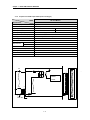
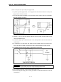
• Restart mode is executed as the figure given below when the power has been re-applied during execution of the
CPU module
Power ON
Operation mode
STOP
Operation in the STOP mode
RUN
Data that remains at
power failure
Abnormal
Normal
Restart mode
Cold Restart
Warm Restart
Warm Restart execution
Cold Restart execution
RUN mode
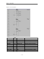
4) Data initialization according to the restart mode
The variables relating to the restart mode are classified into three types, i.e, default variable, initialization
variable and retain variable. The following table shows the initialization method for each type variable.
Mode
Cold
Warm
Variable type
Default
Initialized with ‘0’
Initialized with ‘0’
Retain
Initialized with ‘0’
Previous value is retained
Initialized with the user Initialized with the user defined
Initialization
defined value
value
Initialized with the user
Retain & Initialization
Previous value is retained
defined value
REMARK
1) Definitions
(1)Default variable : A variable whose initial value is not defined or previous value will not be retained.
(2)Initialization variable : A variable whose initial value is defined.
(3)Retain variable : A variable whose previous value will be retained.
4 - 29
Chapter 4. CPU module
4.5.2 Self-diagnosis
1) Functions
(1) The self-diagnosis function permits the CPU module to detect its own errors.
(2) Self-diagnosis is carried out when the PLC power supply is turned on and when an error occurs the
PLC is in the RUN state. If an error is detected, the system stops operation to prevent faulty PLC
operation.
2) Error flag
If an error occurs, it will be stored to the following flags and the STOP LED flickers.
• Representative system error flag : _CNT_ER
• Representative system warning flag : _CNF_WAR
REMARK
1) Refer to 12.5 Error Code List of Chapter 12. Troubleshooting for details of contents of self-diagnosis
and corrective actions.
4 - 30
Chapter 4. CPU module
4.5.3 Remote function
The CPU module can be controlled by external operations (from GMWIN and computer link module, etc.). For
remote operation, set the mode setting switch of CPU module to remote position.
1) Remote RUN/STOP
(1) The remote RUN/STOP permits external operations to RUN/STOP the CPU module under the condition
that the mode setting switch of CPU module is in the remote position.
(2) This function is convenient when the CPU module is located on the place where it is difficult to control the
CPU module or the user want to control the CPU module in the control panel from outside.
2) Remote PAUSE
(1) The remote PAUSE permits external operations to execute PAUSE operations under the condition that the
mode setting switch of CPU module is in the remote position. The PAUSE operations stop the CPU module
operation processing while maintaining the On/Off state of the output module.
(2) This function is convenient when the user wants to maintain the ON state of the output module under the
condition the CPU module has been stopped.
3) Remote DEBUG
(1) This function permits external operations to execute DEBUG operations under the condition that the mode
setting switch of CPU module is in the remote position. The DEBUG operations execute programs complying
with the specified operation conditions.
(2) This function is convenient when program execution or contents of any data are checked for debugging of
the program.
4) Remote reset
(1) This function permits remote operations to reset the CPU module, which locates in the place where direct
operations cannot be applied, when an error has occurred.
REMARK
1) For remote function operations, refer to the GMWIN User’s Manual Chapter 7. On-line.
4 - 31
Chapter 4. CPU module
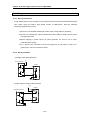
4.5.4 I/O Force On/Off function
1) Force On/Off setting method
Force on/off setting is applied to input area and output area.
Force on/off should be set for each input and output, the setting operates from the time that ‘Force I/O
setting enable’ is set.
This setting can be done when I/O modules are not really loaded.
2) Force on/off Processing timing and method
(1) Force Input
• After data have been read from input modules, at the time of input refresh the data of the junctions
which have been set to force on/off will be replaced with force setting data to change the input image
area. And then, the user program will be executed with real input data and force setting data.
(2) Force output
• When a user program has finished its execution the output image area has the operation results. At
the time of output refresh the data of the junctions which have been set to force on/off will be replaced
with force setting data and the replaced data will be output. However, the force on/off setting does not
change the output image area data while it changes the input image area data.
(3) Force on/off processing area
• Input/output areas for force on/off setting are larger than the real I/O areas. If remote I/O is specified
using this area, the force on/off function is as just available in it as in the basic I/O areas.
(4) Precautions
• Turning the power off and on, change of the operation mode or operation by reset switch(GM3) does
not change the previous force on/off setting data. They remain within the CPU module and operation is
executed with the same data.
• Force I/O data will not be cleared even in the STOP mode.
• If a program is downloaded or its backup breaks, the force on/off setting data will be cleared. The
operating program in memory differs from the program in the flash memory so that if operation restarts
with the program in the flash memory the on/off setting data will be also cleared.
• When setting new data, disable every I/O settings using the setting data ‘clear’ function and set the
new data.
REMARK
1) For detailed operation, refer to the GMWIN User’s Manual Chapter 7 ‘Force I/O setting.
4 - 32
Chapter 4. CPU module
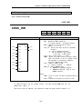
4.5.5 History Log-In
The GM6 CPU stores 3 operation histories such as error occurrence, mode change, and power shut-down.
Each history log-in contains the last 16 operation histories.
1) Error occurrence
• Record occurrence time and error code when an error occurred while the CPU is in RUN mode.
2) Mode change
• Record the mode change time, operation mode, and restart mode when a operation mode is changed.
3) Power failure
• Record the occurrence time and total occurrence number when the AC failure occur while the CPU is
in RUN mode.
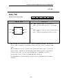
4.5.6 External Device Error Diagnosis function
Flags are given for the user to implement easily the program in which the error detection of external
devices and system stop and warning are coded. By use of these flags, error indication of external devices
is possible without complex programming and monitoring of the error location can be done without special
tools (GMWIN, etc.) or source programs.
1) External device fault detection and classification
(1) The user program detects external device faults. The faults are classified into fatal fault( error), where
the PLC stops its operation, and ordinary fault(warning), where operation continues.
(2) The flag ANC_ERR[n] is used to indicate error. The flag ANC_WN[n] is used to indicate warning.
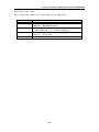
2) External Device Fatal-fault (Error) Processing.
(1) If an error of external device is detected and the error type, where other value than 0 is used, is written
to the system flag ANC_ERR[n], the flag will checked at the time that scan program finishes its
execution. If an error is indicated on the flag, it will be also indicated on the _ANNUN_ER of the
representative system error flag _CNF_ER, the PLC turns all output modules off and the error state
will be same as the PLC self-diagnosis.
(2) The user can know the cause of error by use of the GMWIN, and also by direct monitoring of the flag
_ANC_ERR[n].
(3) As the flag _ANC_ERR[n] has sixteen elements(n : 0 to 15), the user can classify error states largely.
User defined error No. can be written to the elements. A number of 1 to 65535 is usable.
Example)
Error detection
MOV
10
4 - 33
Chapter 4. CPU module
3) External device Ordinary-fault (Warning) Processing.
(1) If a warning of external device is detected and the corresponding flag of the system flag _ANC_WB[n]
is set to on, the flag will checked from the _ANC_WB[0] at the time that scan program finishes its
execution. If an error is indicated on the flag, it will be also indicated on the _ANNUN_WR of the
representative system warning flag _CNF_WAR. External device waning numbers will be written to
from _ANC_WAR[0] to _ANC_WAR[7] according to occurrence sequence.
(2) The user can know the cause of error by use of the GMWIN, and also by direct monitoring of the flags
_ANC_WAR[n] and _ANC_WB[n].
(3) If an external device waning is removed, that is, the elements of _ANC_WAR[n] are released from
warning, the corresponding _ANC_WAR[n] will be automatically cleared. If all element flags are
cleared, the flag _ANNUN_WR of the system flag _CNF_WAR will be reset.
4 - 34
Chapter 4. CPU module
Example
Error detection
_ANNUN_WR
_ANC
_WAR[0]
_ANC
_WAR[1]
_ANNUN_WR
_ANC
_WAR[0]
_ANC
_WAR[1]
_ANNUN_WR
_ANC
_WAR[0]
_ANC
_WAR[1]
_ANNUN_WR
_ANC
_WAR[0]
_ANC
_WAR[1]
(
)
=
=
=
=
=
=
=
=
=
1
10
0
0
0
0
0
0
0
If the user program had detected a system fault and set
_ANC_WB[10] to ON, the states of _ANNUN_WR
and
_ANN_WAR [0..7] will be shown as left after the scan has been
finished
=
=
=
=
=
=
=
=
=
1
10
0
0
0
0
0
0
0
After the next scan has been finished, if the numbers 1, 2, 3, 10, 15 ,
40 , 50, 60 and 75 of _ANC_WB[n] are tuned on _ANC_WAR[n] will be
shown as left
=
=
=
=
=
=
=
=
=
1
10
0
0
0
0
0
0
0
=
=
=
=
=
=
=
=
=
1
10
0
0
0
0
0
0
0
As the number 10 has turned on (has occurred) in the previous scan,
though the number 10 has lower priority than the numbers 1, 2 and 3, it
will be the lower element of _ANC_WAR[n]. The _ANC_WB[75] is not
indicated as it is turned on and the warning that occurred before has
written to the _ANC_WAR[n].
After the next scan has been finished, if the numbers 1, 2, 3, 10, 15 ,
40 , 50, 60 and 75 of _ANC_WB[n] are tuned on _ANC_WAR[n] will be
shown as left.
The No. 10 warning has been released the content of _ANC_WAR[0] will
be cleared and the contents of _ANC_WAR[1..7] will shift into the lower
elements. The content of _ANC_WAR[7] will has been cleared by the
shifting and the content of _ANC_WB[75] will be written to _ANC_WAR[7].
If all warnings indicated on the _ANC_WB[n] are released during
operation, the _ANNUN_WR and _ANC_WAR[n] will be shown as left.
4 - 35
Chapter 4. CPU module
4.6 Memory Configuration
The CPU module includes two types of memory that are available by the user. One is program memory which is used
to store the user programs written to implement a system by the user. The other is data memory which stores data
during operation.
1) Program memory configuration
The table given below shows the contents to be stored and the storage capacity of program memory.
Item
Memory Capacity
Overall program memory area
68 k bytes
Parameter area
• Basic parameter area
• I/O parameter area
• High speed link parameter area
• Interrupt setting information area
Program area
• Scan program area
• Task program area
• User defined function/function block area
• Standard library area
• Access variable are
• Variable initialization information area
• Protective variable specification information area
2 k bytes
66 k bytes
2) Data memory Configuration
The table given below shows the contents to be stored and the storage capacity of program memory.
Item
Memory Capacity
Overall data memory area
System area
• I/O information table
• Force I/O table
System flag area
Input image area (%IX)
Output image area (%QX)
Direct variable area (%M)
Symbolic variable area (maximum)
32 k bytes
1 k bytes
1.5 k bytes
128 bytes
128 bytes
2 to 8 k bytes
29 k bytes – the size of direct variable
area
3 k bytes
Stack area
4 - 36
Chapter 4. CPU module
3) Purpose
(1) System area
it used to store the self-created data of the CPU module for system management and GMWIN system control
data.
(2) System flag area
it used to user flags and system flags. The user operates it with flag name.
(3) Input image area
It used to store input data read from input modules. Overall size is %IX0.0.0 to %IX1.7.63. The redundant area
(Actual input module is not installed) can be used as auxiliary relay in user program. Especially, it is
convenient to use the data storing area of remote input through high speed link.
(4) Output image area
It used to store operation results. The stored data are automatically output to output modules. Overall size
is %QX0.0.0 to %QX1.7.63. The redundant area (Actual output module is not installed) can be used as
auxiliary relay in user program. Especially, it is convenient to use the data storing area of remote output through
high speed link.
(5) Direct variable area
The user can use this area to access direct memory data through the variable names such as %MX0, %MB0,
%MW0 and %MD0, which was pre-defined by the system. Memory size is defined when program is made by
user and it refers to ‘App1. System Definitions’.
(6) Symbolic variable area
It used to store the variables that the user created, that is, whose names the user defined when writing a
program. Global variables and instance memory are located in this area. The variables used in program
blocks locates in the ‘PB instance memory’ of the program, and the memory used in function block locates in
the ‘FB instance memory’.
The maximum size of the PB instance memory is 32 Kbytes. If the used size overruns the maximum size,
divide the program blocks or use global variables.
4 - 37
Chapter 4. CPU module
4.7
I/O No. Allocation Method
1) I/O No. allocation means to give an address to each module in order to read data from input modules and output
data to output modules.
2) Fixed 64 points are allocated to each module for I/O points.
3) Fixed 64 points are allocated regardless of mounting/dismounting or type of modules.
4) The following shows I/O No. allocation method.
Input
: %
I
X
0.
0.
0
Output :% Q X 0. 1. 15
Contact number on I/O module
0 ~ 63
Slot number of Base
0~7
Base number.
1)
0~1
REMARK
1) Although there is no expansion base, A base having more than 8 I/O slot which has a plan to develop
set by 1 as base number.
4 - 38
Chapter 4. CPU module
4.8 Names of Parts
The following describes the names and functions of parts of the CPU module.
①
②
③
GM6
④
⑤
⑥
⑦
No.
Name
Function
RUN LED
Indicates the operation status of the CPU module.
• On : when the CPU module operates with the mode setting switch in the
local or remote RUN state.
• Off : when the followings occur
The voltage is not normally supplied to the SPU module.
The mode setting switch is in the STOP or PAU/REM state.
An error which makes operation stop is detected.
2
STOP LED
• On : when the mode setting switch is in the local or remote STOP state.
• Off : when the followings occur
The mode setting switch is in the local RUN or local PAUSE state.
The operation state is in the RUM/PAUSE/DEBUG state.
• Flickering : when an error is detected by self-diagnosis during operation.
3
Battery installing connector
1
4
Mode setting switch
5
DIP S/W for flash memory
It used to connect to the backup battery.
Sets the operation mode of the CPU module. .
• RUN : Program operation is executed.
• STOP : Program operation is temporarily stopped.
• PAU/REM :
PAUSE : Program operation is temporarily stopped.
REMOTE: Used for the remote operation
See chap 6.
4 - 39
Chapter 4. CPU module
No.
Name
Function
GM6-CPUA : N/A (The terminal block is not installed)
GM6-CPUB : RS-422/485 interface terminal block
GM6-CPUC : High speed counter input terminal block
GM6-CPUB
Terminal block for built-in
special function
6
GM6-CPUC
RDA
φA 24V
RDB
φB 24V
SDA
COM
SDB
PRE 24V
SG
Operation Mode
6
RS-232C connector
PRE
0V
It used to connect to peripheral devices(GMWIN, etc.)
GM6-CPUA and GM6-CPUC have built-in RS-232C interface function, and
it shares the RS-232C connector with peripheral device interface.
(Refer the chapter 13 for details)
REMARK
The followings shows the LED status complying with the operation mode, and the operation mode complying with
the position of the mode setting switch.
1) LED status complying with the operation mode
LED Status
RUN
STOP
Local Run
On
Off
Local Stop
Off
On
Local Pause
Off
Off
Remote Run
On
Off
Remote Stop
Off
On
Remote Pause, Remote Debug
Off
Off
2) Operation mode complying with the position of the mode setting switch.
Position of Mode switch
STOP
Operation Mode
PAU/REM
Remote Stop
l
PAU/REM
RUN
Local Run
RUN
PAU/REM
Local Pause
1)
Change of remote mode is available only after the operation mode has entered into the remote STOP mode.
caution
1) In case of local pause disable, it operated as Remote Run.
4 - 40
Chapter 5. BATTERY
Chapter 5.
BATTERY
5.1 Specifications
Item
Specifications
Normal voltage
3.0 VDC
Warranty life time
5 years
Application
Programs and data backup, and RTC runs in power failure
Specifications
Lithium Battery, 3 V
External dimension (mm)
Φ14.5 × 26
5.2 Handling Instructions
1) Do not heat or solder its terminals.
2) Do not measure its voltage with a tester or short circuit.
3) Do not disassemble.
5.3 Battery Replacement
Backup battery needs periodic exchange. When the battery exchange, it should be done at power on, otherwise
some or all data will be lost.
The following shows the battery replacement procedure.
Battery replacement
Open the cover of the CPU module.
Release the existing battery from the holder and disconnect the connector.
Insert a new battery into the holder in the exact direction and connect the
connector.
No
Stop LED flickering?
Yes
Complete
Battery error
5-1
Chapter 6. MEMORY MODULE
Chapter. 6
USING THE USER PROGRAM IN FLASH MEMORY
This chapter describes user program storage and operation it.
Flash memory is used to store a user program and installed in PLC.
6.1
Structure
Dip switch for operation
Flash memory
6.2 How to use
Read / Write is available to flash memory in accordance with selection of DIP switch.
Selection of DIP switch for flash
memory
ON
ON
Operation
PLC is operated by the program in flash memory when power on or PLC
reset.
PLC recognize that no program is in flash memory.
( Caution : Lower switch should be at the off position. )
User program can be written to flash memory at the PLC stop mode and then the selection of switch is ignored.
6-1
Chapter 7. INPUT AND OUTPUT MODULES
Chapter. 7
DIGITAL INPUT AND OUTPUT MODULES
7.1 Notes on Selecting Input and Output Modules
The followings describe instructions for selection of digital I/O modules that will be used in the GLOFA-GM6
series.
1) The types of digital input are current sink input and current source input.
When selecting DC input modules consider the specifications of those input devices as the wiring method of
the external input power supply varies complying with the type of digital input.
In the GM6 series, the types are dedicated source input and source/sink common DC input.
2) Maximum simultaneous input points differs with the type of a module. Check the specifications of the input
module to be applied before use.
3) Use transistor or triac output modules with a load that is frequently opened and closed or with an inductive load
as, in those cases, the life span of a relay output module will become shorter than specified.
7- 1
Chapter 7. INPUT AND OUTPUT MODULES
7.2 Digital Input Module Specifications
7.2.1 8-points 12 / 24 VDC input module (source / sink type)
Model
DC Input Module
G6I-D21A
Specifications
Number of input points
8 points
Insulation method
Rated input voltage
Photo coupler
12 VDC
24 VDC
Rated input current
3 mA
7 mA
Operating voltage range
Maximum simultaneous input points
10.2 VDC to 28.8 VDC (ripple: less than 5%)
100%(8 points/COM) simultaneously ON
ON voltage/ON current
9.5 VDC or higher / 3.5 mA or higher
OFF voltage/OFF current
Input impedance
5 VDC or lower / 1.5 mA or lower
Approx. 3.3 kΩ
OFF → ON
5 ms or less
ON → OFF
Common terminal
5 ms or less
8 points/COM
Internal current consumption
40 mA
Operating indicator
External connections
LED turns on at ON state of input
9-points terminal block connector(M3 × 6 screws)
Weight
0.12 kg
Response time
00
1
Photo coupler
DC5V
R
G6I-D21A
00
R
07
Internal
Circuit
COM 8
9
01
02
03
DC12/24V
04
05
06
07
COM
7- 2
Chapter 7. INPUT AND OUTPUT MODULES
7.2.2 16-points 12 / 24 VDC input module (source / sink type)
Model
Specifications
DC Input Module
G6I-D22A
Number of input points
16 points
Insulation method
Photo coupler
Rated input voltage
Rated input current
12 VDC
3 mA
Operating voltage range
10.2 VDC to 28.8 VDC (ripple: less than 5%)
Maximum simultaneous input points
ON voltage/ON current
100%(8 points/COM) simultaneously ON
9.5 VDC or higher / 3.5 mA or higher
OFF voltage/OFF current
5 VDC or lower / 1.5 mA or lower
Input impedance
OFF → ON
Approx. 3.3 kΩ
5 ms or less
ON → OFF
5 ms or less
Response time
24 VDC
7 mA
Common terminal
Internal current consumption
8 points/COM
70 mA
Operating indicator
LED turns on at ON state of input
External connections
Weight
18-points terminal block connector(M3 × 6 screws)
0.15 kg
00
DC5V
1
R
G6I-D22A
R
07
COM
00
8
Internal
9
Circuit
DC12 / 24V
08
01
02
03
04
05
06
07
COM
08
09
10
10
11
12
13
15
14
15
17
COM
COM 18
Terminal Block Number
DC12 / 24V
7- 3
Chapter 7. INPUT AND OUTPUT MODULES
7.2.3 16-points 24 VDC input module (source type)
Model
Specifications
DC Input Module
G6I-D22B
Number of input points
16 points
Insulation method
Photo coupler
Rated input voltage
Rated input current
24 VDC
7 mA
Operating voltage range
20.4 VDC to 28.8 VDC (ripple: less than 5%)
Maximum simultaneous input points
ON voltage/ON current
100%(8 points/COM) simultaneously ON
15 VDC or higher/4.3 mA or higher
OFF voltage/OFF current
5 VDC or lower/1.7 mA or lower
Input impedance
OFF → ON
Approx. 3.3 kΩ
5 ms or less
ON → OFF
5 ms or less
Response time
Common terminal
Internal current consumption
8 points/COM
70 mA
Operating indicator
LED turns on at ON state of input
External connections
Weight
18-points terminal block connector(M3 × 6 screws)
0.15 kg
00
DC5V
1
R
G6I-D22B
R
07
COM
00
01
8
Internal
9
Circuit
DC24V
08
02
03
04
05
06
07
COM
08
10
09
15
10
11
12
13
14
17
15
COM
COM 18
Terminal Block Number
DC24V
7- 4
Chapter 7. INPUT AND OUTPUT MODULES
7.2.4
32-points 12 / 24 VDC input module (source / sink type)
DC Input Module
Model
Specifications
G6I-D24A
32 points
Photo coupler
12 VDC
24 VDC
3 mA
7 mA
10.2 to 28.8 VDC (ripple: less than 5%)
60% simultaneously ON
9.5 VDC or higher / 3.5 mA or higher
5 VDC or lower / 1.5 mA or lower
Number of input points
Insulation method
Rated input voltage
Rated input current
Operating voltage range
Maximum simultaneous input points
ON voltage/ON current
OFF voltage/OFF current
Input impedance
OFF → ON
Response time
ON → OFF
Common terminal
Internal current consumption
Operating indicator
External connections
Weight
00
1
Approx. 3.3 kΩ
5 ms or less
5 ms or less
32 points/COM
75 mA
LED turns on at ON state of input
37-point terminal block connector(M3 × 6 screws)
0.11 kg
DC5V
R
1
00
R
2
03
3
04
4
5
09
6
11
7
13
8
15
9
17
10
10
12
Circuit
14
16
31
18 1
19
20
21
22
23
24
25
26
27
28
29
30
31
COM
35
17
36
18
37
23
24
25
26
27
28
29
11
30
12
31
13
32
14
33
15
34
16
35
17
36
18
19
19
DC12 / 24V
22
07
08
12
21
05
06
Internal
20
01
02
Connector Pin Number
7- 5
37
Chapter 7. INPUT AND OUTPUT MODULES
7.2.5. 32-points 24 VDC input module (source type)
Number of input points
Insulation method
Rated input voltage
Rated input current
Operating voltage range
Maximum simultaneous input points
ON voltage/ON current
OFF voltage/OFF current
Input impedance
OFF → ON
Response time
ON → OFF
Common terminal
Internal current consumption
Operating indicator
External connections
Weight
00
DC Input Module
Model
Specifications
1
G6I-D24B
32 points
Photo coupler
24 VDC
7 mA
20.4 to 28.8 VDC (ripple: less than 5%)
60% simultaneously ON
15 VDC or higher / 4.3 mA or higher
5 VDC or lower / 1.7 mA or lower
Approx. 3.3 kΩ
5 ms or less
5 ms or less
32 points/COM
75 mA
LED turns on at ON state of input
37-point terminal block connector(M3 × 6 screws)
0.11 kg
DC5V
R
1
00
R
2
03
3
04
4
5
09
6
11
7
13
8
15
9
10
12
Circuit
14
16
31
17
18 1
19
20
21
22
23
24
25
26
27
28
29
30
31
COM
35
17
36
18
37
23
24
25
26
27
28
10
29
11
30
12
31
13
32
14
33
15
34
16
35
17
36
18
19
19
DC24V
22
07
08
12
21
05
06
Internal
20
01
02
Connector Pin Number
7- 6
37
Chapter 7. INPUT AND OUTPUT MODULES
7.2.6
8-points 110 VAC input module
AC Input Module
Models
Specifications
G6I-A11A
Number of input points
8 points
Insulation method
Photo coupler
Rated input voltage
Rated input current
100 to 120 VAC (50/60 Hz)
11 mA (110 VAC / 60 Hz)
Operating voltage range
85 to 132 VAC (50/60 Hz ± 3 Hz)
Maximum simultaneous input points
Inrush current
100%(8 points / COM) simultaneously ON
300 mA, 0.3 ms or lower (132 VAC)
ON voltage/ON current
80 VAC or higher / 5 mA or higher
OFF voltage/OFF current
Input impedance
30 VAC or lower / 2 mA or lower
Approx. 15 kΩ
OFF → ON
15 ms or less
ON → OFF
Common terminal
25 ms or less
8 points/COM
Internal current consumption
60 mA
Operating indicator
External connections
LED turns on at ON state of input
9-point terminal block connector(M3 × 6 screws)
Weight
0.14 kg
Response time
00
1
DC5V
R
R
G6I-A11A
R
00
Internal
Circuit
01
02
03
04
05
06
07
07
8
COM
COM
9
AC 110V
Terminal Block Number
7- 7
Chapter 7. INPUT AND OUTPUT MODULES
7.2.7
8-points 220 VAC input module
Number of input points
Insulation method
Rated input voltage
Rated input current
Operating voltage range
Maximum simultaneous input points
Surge input current
ON voltage/ON current
OFF voltage/OFF current
Input impedance
OFF → ON
Response time
ON → OFF
Common terminal
Internal current consumption
Operating indicator
External connections
Weight
00
GM4
Model
Specifications
1
G6I-A21A
8 points
Photo coupler
200 to 240 VAC (50/60 Hz)
11 mA (220 VAC / 60 Hz)
170 to 264 VAC (50/60 Hz ± 3 Hz)
100%(8 points / COM) simultaneously ON
600 mA, 0.12 ms or lower (264 VAC)
80 VAC or higher / 5 mA or higher
30 VAC or lower / 2 mA or lower
Approx. 20 kΩ
15 ms or less
25 ms or less
8 points/COM
41 mA
LED turns on at ON state of input
9-point terminal block connector(M3 × 6 screws)
0.14 kg
DC5V
R
R
G6I-A21A
R
00
Internal
Circuit
01
02
03
04
05
06
07
07
8
COM
COM
9
AC 220V
Terminal Block Number
7- 8
Chapter 7. INPUT AND OUTPUT MODULES
7.3 Digital Output Module Specifications
7.3.1.
8-point relay output module
Relay Output Module
Models
Specifications
G6Q-RY1A
8 points
Photo coupler
24 VDC 2A(resistance)/point, 5 A/ COM
220 VAC 2A(COSΨ = `1)/point, 5A/COM
5 VDC / 1 mA
250 VAC, 110 VDC
1200 times per hour
None
20 million times or more
Rated load voltage/current 100000 times or more
200 VAC 1.5 A, 240 VAC 1 A (COSΨ = 0.7) : 100000 times or more
200 VAC 1 A, 240 VAC 0.5 A (COSΨ = 0.35) : 100000 times or more
24 VAC 1.5 A, 100 VDC 0.1 A (L/R= 7 ms) : 100000 times or more
10 ms or less
12 ms or less
1 points/COM
250mA
LED turns on at ON state of output
18-point terminal block connector (M3 × 6 screws)
0.19 kg
Number of output points
Insulation method
Rated load voltage & current
Minimum load voltage/current
Maximum load voltage/current
Maximum switching frequency
Surge absorber
Mechanical
Service life
Electrical
Off → On
On → Off
Common terminal arrangement
Internal current consumption
Operation indicator
External connections
Weight
Response time
00
L
1
DC5V
DC5V
2
G6Q-RY1A
Coil
R
L
Relay
00
COM
01
L
AC110/220V
COM
02
L
COM
Internal
Circuit
L
03
COM
R
L
04
COM
15 07
L
16
L
L
05
COM
06
COM
L
07
COM
NC
NC
17
18 NC
Terminal
Block No.
7- 9
Chapter 7. INPUT AND OUTPUT MODULES
7.3.2.
16-point relay output module
Specifications
G6Q-RY2A
Number of output points
Insulation method
Rated load voltage & current
16 points
Photo coupler
24 VDC 2A(resistance)/point, 5 A/ COM
220 VAC 2A(COSΨ = `1)/point, 5A/COM
5 VDC / 1 mA
250 VAC, 110 VDC
1200 times per hour
None
20 million times or more
Rated load voltage/current 100000 times or more
200 VAC 1.5 A, 240 VAC 1 A (COSΨ = 0.7) : 100000 times or more
200 VAC 1 A, 240 VAC 0.5 A (COSΨ = 0.35) : 100000 times or more
24 VAC 1.5 A, 100 VDC 0.1 A (L/R= 7 ms) : 100000 times or more
10 ms or less
12 ms or less
8 points/COM
415mA
LED turns on at ON state of output
18-point terminal block connector (M3 × 6 screws)
0.19 kg
Minimum load voltage/current
Maximum load voltage/current
Maximum switching frequency
Surge absorber
Mechanical
Service life
Relay Output Module
Models
Electrical
Off → On
On → Off
Common terminal arrangement
Internal current consumption
Operation indicator
External connections
Weight
Response time
1
DC5V
DC5V
00
L
G6Q-RY2A
Coil
R
L
Relay
8
9
Internal
Circuit
02
03
04
05
06
07
07
L
110/220 VAC
R
10
08
L
00
01
COM
L
08
09
10
11
12
17
18
15
L
110/220 VAC
Terminal Block Number
7- 10
13
14
15
COM
Chapter 7. INPUT AND OUTPUT MODULES
7.3.3 16-point transistor output module (sink type)
Specifications
Transistor Output Module
Models
G6Q-TR2A
Number of output points
Insulation method
Rated load voltage/current
Operating load voltage range
Maximum load current
Off leakage current
Maximum inrush current
Maximum voltage drop at ON circuit
Surge absorber
Response
Off → On
time
On → Off
Common terminal arrangement
Internal current consumption
External
Voltage
power supply Current
Operation indicator
External connections
Weight
16 points
Photo coupler
12/24 VDC
10.2 to 26.4 VDC
0.5 A /point, 4 A / COM
0.1 mA
4 A, 10 ms or less
1.5 VDC(0.5A)
Clamp Diode
2 ms or less
2 ms or less
16 points/COM
185 mA
24 VDC ± 10 % (ripple voltage : 4VP-P or less)
48 mA or less (all points ON)
LED turns on at ON state of output
18-point terminal block connector (M3 × 6 screws)
0.18 kg
17
DC5V
1
R
00
L
G6Q-TR2A
L
00
01
02
03
04
Internal
05
06
R
07
08
Circuit
09
10
16
18
15
L
7- 11
15
COM
DC 24V
Terminal Block Number
11
12
13
14
Chapter 7. INPUT AND OUTPUT MODULES
7.3.4
16-point transistor output module (source type)
Transistor Output Module
Models
Specifications
G6Q-TR2B
Number of output points
Insulation method
Rated load voltage/current
Operating load voltage range
Maximum load current
Off leakage current
Maximum inrush current
Maximum voltage drop at ON circuit
Surge absorber
Response
Off → On
time
On → Off
Common terminal arrangement
Internal current consumption
External
Voltage
power supply Current
Operation indicator
External connections
Weight
16 points
Photo coupler
12/24 VDC
10.2 to 26.4 VDC
0.5 A /point, 4 A / COM
0.1 mA
4 A, 10 ms or less
1.5 VDC(0.5A)
Clamp Diode
2 ms or less
2 ms or less
16 points/COM
185 mA
24 VDC ± 10 % (ripple voltage : 4VP-P or less)
48 mA or less (all points ON)
LED turns on at ON state of output
18-point terminal block connector (M3 × 6 screws)
0.18 kg
DC5V
Transistor
G6Q-TR2B
R
R
1
Photo
Coupler
00
L
Internal
Circuit
L
00
01
02
03
04
05
06
07
08
09
10
1
17
15
L
7- 12
15
COM
18
Terminal Block No.
11
12
13
14
DC12/24V
Chapter 7. INPUT AND OUTPUT MODULES
7.3.5
32-point transistor output module (sink type)
Transistor Output Module
Models
Specifications
G6Q-TR4A
Number of output points
Insulation method
Rated load voltage/current
Operating load voltage range
Maximum load current
Off leakage current
Maximum inrush current
Maximum voltage drop at ON circuit
Surge absorber
Response
Off → On
time
On → Off
Common terminal arrangement
Internal current consumption
External
Voltage
power supply
Current
Operation indicator
External connections
Weight
32 points
Photo coupler
12/24 VDC
10.2 to 26.4 VDC
0.1 A / point, 2 A /COM
0.1 mA or less
4 A, 10 ms or less
1.0 VDC
None
2 ms or less
2 ms or less
32 points/COM
139 mA
24 VDC ± 10 % (ripple voltage : 4VP-P or less)
36 mA or less (24 VDC/COM)
LED turns on at ON state of output
37-pin D Sub-connector
0.11 kg
DC5V
R
Internal
L
17
18
1
00
L
00
01
02
03
04
05
1
2
20
21
3
22
R
Circuit
16
19
36
37
31
L
L
24
25
26
27
28
29
30
31
14
14
33
15
34
16
17
18
19
Connector Pin Number
7- 13
32
35
36
37
Chapter 7. INPUT AND OUTPUT MODULES
7.3.6
32-point transistor output module (source type)
Specifications
Transistor Output Module
Models
Number of output points
Insulation method
Rated load voltage/current
Operating load voltage range
Maximum load current
Off leakage current
Maximum inrush current
Maximum voltage drop at ON circuit
Surge absorber
Response
Off → On
time
On → Off
Common terminal arrangement
Internal current consumption
External
Voltage
power supply
Current
Operation indicator
External connections
Weight
G6Q-TR4B
32 points
Photo coupler
12/24 VDC
10.2 to 26.4 VDC
0.1 A / point, 2 A /COM
0.1 mA or less
4 A, 10 ms or less
1.0 VDC
None
2 ms or less
2 ms or less
32 points/COM
139 mA
24 VDC ± 10 % (ripple voltage : 4VP-P or less)
36 mA or less (24 VDC/COM)
LED turns on at ON state of output
37-pin D Sub-connector
0.11 kg
DC5V
1
00
1
R
00
L
2
03
3
05
4
07
5
09
6
11
7
13
8
15
9
17
10
19
11
21
12
23
13
25
14
04
06
08
10
12
14
16
Internal circuit
18 1
20
R
20
01
02
21
22
23
24
25
26
27
28
29
30
22
31
24
35
17
18
36
31
L
26
27
32
33
15
28
34
29
30 31
16
35
17
COM
COM
36
18
19
37
19
37
Connector Pin No.
COM : 17,18,36
:17,18,36
The total current of each 8 points (0~7,8~15,16~23,and 24~31) should be lower than 600mA.
7- 14
Chapter 7. INPUT AND OUTPUT MODULES
7.3.7
8-point triac output module
Models
Specifications
Number of output points
Insulation method
Rated load voltage
Minimum load voltage
Maximum load current
Minimum load current
Off leakage current
Maximum inrush current
Maximum voltage drop at ON circuit
Surge absorber
Off → On
Response time
On → Off
Common terminal arrangement
Internal current consumption
Operation indicator
External connections
Weight
Triac Output Module
G6Q-SS1A
8 points
Photo coupler
100 to 240 VAC (50 to 60 Hz)
264 VAC
1 A / point, 4 A / 1 COM
20 mA
2.5 mA (220 VAC, 60 Hz)
40 A, 10 ms or less
1.5 VAC or less (2 A)
Varistor (387 to 473 V), C.R absorber
1ms or less
1ms + 0.5 cycle or less
8 points/COM
210 mA
LED turns on at ON state of output
9-point terminal block connector (M3 × 6 screws)
0.16 kg
DC5V
DC5V
00
L
1
R
G6Q-SS1A
L
R
R
8
9
07
L
00
01
02
03
Internal
Circuit
R
SSR
110/220 VAC
04
05
06
07
COM
Terminal Block Number
7- 15
Chapter 8. POWER SUPPLY MODULES
Chapter 8.
POWER SUPPLY MODULE
This chapter describes the selection method, type and specifications of the power supply module.
8.1 Selection of power supply module
Selection of the power supply module is determined by the total current consumption of digital input modules,
special modules and communications modules, etc. whose powers are supplied by the power supply module.
If total load overrun the rated output capacity , the system will not normally operate. When configuring a
system, select a power supply module with due consideration of current consumption of each module.
1) Current consumption GM6 series modules (unit: mA)
Models
Current
Consumption
GM6-CPUA
170
GM6-CPUB
210
GM6-CPUC
170
G6I-D21A
40
G6I-D22A
70
G6I-D22B
70
G6I-D24A
75
G6I-D24B
75
G6I-A11A
35
G6I-A21A
35
G6Q-RY1A
210
G6Q-RY2A
400
Triac output module
G6Q-SS1A
190
Positioning module
G6F-POPA
345
Modules
CPU module
24 VDC input
module
110 VAC input
module
220 VAC input
module
Relay output module
Modules
Transistor output
module
A/D conversion module
D/A conversion module
High speed counting
module
Computer link module
Fnet I/F module
Dnet I/F module
8- 1
Models
Current
Consumption
G6Q-TR2A
180
G6Q-TR2B
170
G6Q-TR4A
140
G6Q-TR4B
145
G6F-AD2A
50
G6F-DA2V
50
G6F-DA2I
50
G6F-HSCA
220
G6L-CUEB
140
G6L-CUEC
180
G6L-FUEA
215
G6L-RBEA
215
G6L-DUEA
220
G6L-DSIA
155
G6L-DSQA
240
Chapter 8. POWER SUPPLY MODULES
8.2 Specifications
Item
Input
GM6-PAFA
GM6-PDFA
85 to 264 VAC
GM6-PD3A
Input voltage
85 to 264 VAC
Input
frequency
50 / 60 Hz (47 to 63 Hz)
Input current
0.7 / 0.35 A
Inrush current
30 A or less
40A or less
Efficiency
70% or more (rated load, 110/220 VAC)
60% or more (rated input, rated load)
Input fuse
250 VAC / 2A
250VAC / 3A
Allowable
momentary
power failure
Output
GM6-PAFB
12 / 24VDC
24VDC
–
0.7 / 0.35 A
1.5A (12VDC)
20 ms or less
0.7A (24VDC)
1ms or less
Output voltage
5 VDC
Output current
5 VDC : 2 A
Over-current
protection
5 VDC : 2.2 A or more
Output voltage
24 VDC
± 15VDC
–
Output current
24 VDC : 0.3 A
+15 VDC : 0.5 A
-15VDC : 0.2 A
–
24 VDC : 0.33 A or more
+15 VDC : 0.55 A
-15VDC : 0.22 A
–
Over-current
protection
Voltage status indicator
LED turns On at normal output voltage.
–
Used wire specifications
0.75 to 2 mm 2
–
Weight
0.4 kg
REMARK
To use A/D and D/A modules (G6F-AD2A, G6F-DA2V, G6F-DA2I), choose the GM6-PAFB power module.
8- 2
Chapter 8. POWER SUPPLY MODULES
8.3 Names of Parts
The followings describe names of parts and their purposes of the power supply module.
①
②
③
④
⑤
No.
Name
1
Power LED
2
Power input terminal
3
4
LG terminal
FG terminal
24 VDC and DC24G terminal
5
No connection
Purpose
It used to indicate the 5 VDC power supply.
Connect 110 or 220 VAC power. (GM6-PAFA, GM6-PAFB)
Connect 12 / 24VDC power. (GM6-PDFA)
Connect 24VDC power (GM6-PD3A)
Line Ground
Frame Ground
GM6-PAFA It used the 24 VDC power to supply to the other module
GM6-PAFB
GM6-PDFA No connection
GM6-PD3A
8- 3
Chapter 9. BASE BOARD AND EXPANSION CABLE
Chapter 9.
BASE BOARD
9.1 Specifications
1) GM6
Models
GM6-B04M
GM6-B06M
GM6-B08M
Items
Mounting I/O modules
4 modules
6 modules
8 modules
Outer dimensions (mm)
244 × 110 × 62
314 × 110 × 62
384 × 110 × 62
Panel installation hole size
φ4.5 (for M4 screw)
0.24
0.35
0.75
Weight (kg)
9.2 Names of Parts
Hook
Mounting Guide Hole
CPU Module Connector
Module Mounting Guide Rail
Power Module Connector
9-1
I/O Module Connector
Chapter 10. INSTALLATION AND WIRING
Chapter 10.
10.1
INSTALLATION AND WIRING
Installation
10.1.1
Installation Environment
This unit has high reliability regardless of its installation environment, but be sure to check the following for
system reliability and stability.
1) Environment requirements
Avoid installing this unit in locations which are subjected or exposed to :
(1) Water leakage and dust.
(2) Continuous shocks or vibrations.
(3) Direct sunlight.
(4) Dew condensation due to rapid temperature change.
(5) Higher or lower temperatures outside the range of 0 to 55 °C
(6) Relative humidity outside the range of 5 to 95 %
(7) Corrosive or flammable gases
2) Precautions during installing.
(1) During drilling or wiring, do not allow any wire scraps to enter into the PLC.
(2) Install it on locations that are convenient for operation.
(3) Make sure that it is not located on the same panel that high voltage equipment located..
(4) Make sure that the distance from the walls of duct and external equipment be 50 mm or more.
(5)Be sure to be grounded to locations that have good ambient noise immunity.
3) Heat protection design of control box
(1) When installing the PLC in a closed control box, be sure to design heat protection of control box with
consideration of the heat generated by the PLC itself and other devices.
(2)It is recommended that filters or closed heat exchangers be used.
10 - 1
Chapter 10. INSTALLATION AND WIRING
The following shows the procedure for calculating the PLC system power consumption.
1) PLC system power consumption block diagram
2) Power consumption of each part
(1) Power consumption of a power supply module
Approximately 70% of the power supply module current is converted into power and 30% of that 70%
dissipated as heat, i.e., 3/7 of the output power is actually used.
• Wpw = 3/7 {(I5V × 5) + (I24V × 24)} (W)
where, I5V = 5 VDC circuit current consumption of each module
I24V =
24 VDC circuit average current consumption of output modules (with points simultaneously
switched ON). Not for 24 VDC power supplied from external or power supply modules that
has no 24 VDC output.
(2) Total 5 VDC power consumption
The total power consumption of all modules is the power of the 5 VDC output circuit of the power supply
module.
• W5V = I5V × 5 (W)
(3) Average 24 VDC power consumption (with points simultaneously switched ON)
The total power consumption of all modules is the average power of the 24 VDC output circuit of the power
supply module.
• W24V = I24V × 24 (W)
(4) Average power consumption by voltage drop of output modules (with points simultaneously switched ON)
• Wout = Iout × Vdrop × output points × the rate of points switched on simultaneously (W)
Iout : output current (actual operating current) (A)
Vdrop : voltage dropped across each output load (V)
10 - 2
Chapter 10. INSTALLATION AND WIRING
(5) Average power consumption of input circuits if input modules (with points simultaneously switched ON)
• Win = Iin × E × input points × the rate of points switched on simultaneously (W)
Iin : input current (effective value for AC) (A)
E: input voltage (actual operating voltage) (V)
(6) Power consumption of the special module power supply
• Ws = I5V × 5 + I24V × 24 + I100V × 100 (W)
The sum of the above values is the power consumption of the entire PLC system.
• W = WPW + W5V + W24V + WOUT + WIN + WS (W)
Check the temperature rise within the control panel with calculation of that total power consumption(W).
The temperature rise in the control panel is expressed as:
T = W/UA [°C]
W : Power consumption of the entire PLC system (obtained as shown above)
A : Control panel inside surface area (m2)
U : 6 (if the control panel temperature is controlled by a fan, etc.)
4 (if control panel air is not circulated)
10 - 3
Chapter 10. INSTALLATION AND WIRING
10.1.2 Handling Instructions
To installing the temperature-measuring resistor input module, be sure to check the following:
• Do not drop it off, and make sure that strong shock should not be applied.
• Do not unload the PCB from its case. It can cause faults.
• During wiring, be sure to check any foreign matter like wire scraps should not enter into the upper side of the
PLC. If any foreign matter has entered into it, always eliminate it.
• Do not load or unload the module while the power supply is being connected.
1) I/O module handling instructions
The followings explains instructions for handling or installing the input module.
(1) I/O module specifications re-check
Re-check the input voltage for the input module. If a voltage over the maximum switching capacity is
applied, it can cause faults, destruction or fire.
(2) Used wire
Select the wire with due consideration of ambient temperature and rated current. Its minimum
specifications should be AWG22(0.3 mm2) or more.
(3) Environment
When wiring the I/O module, if it locates near a device generating an cause short circuit, destruction or
malfunction.
(4) Polarity
Before applying the power to a module that has polarities, be sure to check its polarities.
(5) Wiring
• Wiring I/O wires with high voltage cable or power supply line can cause malfunction or disorder.
• Be sure that any wire does not pass across during input LED (I/O status will not be clearly identified.
• If an inductive load has been connected to output module, connect parallel surge killer or diode to a
load. Connect the cathode part of diode to the + part of the power supply.
10 - 4
Chapter 10. INSTALLATION AND WIRING
(6) Terminal block
Check its fixing. During drilling or wiring, do not allow any wire scraps to enter into the PLC. It can cause
malfunction and fault.
(7) Be cautious that strong shock does not applied to the I/O module. Do not separate the PCB from its
case.
2) Base board mounting instructions
The following explains instructions for mounting the PLC onto the control panel.
(1) Allow sufficient distance from the upper part of the module for easy module replacement.
(2) Do not mount the PLC in a vertical or horizontal position because it affects on ventilation.
(3) Do not mount the base board together with a large-sized electromagnetic contact or no-fuse breaker,
which produces vibration, on the same panel. Mount them on different panels, or keep the base board
away from such a vibration source.
(4) Mount the wire duct as it is needed.
If the clearances are less than those in Fig 10.1, follow the instructions shown below.
• If the wire duct is mounted on the upper part of the PLC, make the wiring duct clearance 50mm or
less for good ventilation. Also, allow the distance enough to press the hook in the upper part from
the upper part of the PLC.
• If the wire duct is mounted on the lower part of the PLC, make optic or coaxial cables contact it and
consider the minimum diameter of the cable.
(5) To protect the PLC from radiating noise or heat, allow 100 mm or more clearances between it and
parts. Left or right clearance and clearance from other device in the left or right side should be 50 mm
or more.
board
board
[Fig. 10.1] PLC mounting
10 - 5
Chapter 10. INSTALLATION AND WIRING
[Fig.10.2] Clearance from the front device
[Fig. 10.3] Vertical mounting
10 - 6
[Fig 10.4] Horizontal mounting
Chapter 10. INSTALLATION AND WIRING
10.1.3
Mounting and Dismounting of module
The following explains the mounting and dismounting of various modules.
1) Module mounting
• Insert the module to mounting slot with sliding guide.
• Check that the module is firmly mounted onto the base board.
Locking part for Hook
Hook
Sliding
Locked Hook
Note : The CPU module should be mounted on the next of the power module. If the CPU module is mounted other slot
when a power module that has ± 15VDC output (GM6-PAFB), the CPU module will be damaged. Therefore, please be
sure to mount CPU module on the proper slot.
10 - 7
Chapter 10. INSTALLATION AND WIRING
2) Module dismounting
• First, push the locked hook(①) and pull the module with direction of arrow ②.
①
②
10 - 8
Chapter 10. INSTALLATION AND WIRING
10.2 Wiring
The followings explains the wiring instructions for use of the system.
10.2.1
Power Supply Wiring
1) When voltage fluctuations are larger than the specified value, connect a constant-voltage transformer.
2)
Use a power supply which generates minimal noise across wire and across PLC and
ground. (When excessive noise is generated, connect an insulating transformer)
3)
When wiring, separate the PLC power supply from the I/O and power device as shown
below.
10 - 9
Chapter 10. INSTALLATION AND WIRING
4) Notes on using 24 VDC output of the power supply module
• To protect the power supply modules, do not supply one I/O module with 24 VDDC from several power
supply modules connected in parallel.
• If 24 VDC output capacity is sufficient for one power supply module, supply 24 VDC from the external 24
VDC power supply as shown below.
5) Twist the 110 VAC, 220 VAC, and 24 VDC cables as closely as possible. Connect modules with the
shortest possible wire lengths.
7) To minimize voltage drop, use the thickest (max. 2 mm2 ) wires possible for the 100 VAC, 200VAC and
24 VDC cables.
8) Do not bundles the 100 VAC and 24 VDC cables with main-circuit(high voltage, large current) wires or
the I/O signal wires. If possible, provide more than 100 mm distance between the cables and wires.
8) As a lightning-protection measure, connect a surge absorber as shown below.
REMARK
1) Ground the surge absorber (E1) and the PLC(E2) separately from each other.
2) Select a surge absorber making allowances for power voltage rises.
9) Use a insulating transformer or noise filter for protection against noise .
10) Twist every input power supply wires as closely as possible. Do not allow the transformer or noise filter
across the duct.
10 - 10
Chapter 10. INSTALLATION AND WIRING
10.2.2 Input and Output Devices Wiring
1) Applicable size of wire for I/O wiring is 0.3 to 2 mm2. However, it is recommended to use wire of 0.3mm2 for
convenience.
2) Separate the input and output lines.
3) I/O signal wires must be at least 100 mm away from high voltage and large current main circuit wires.
4) When the I/O signal wires cannot be separated from the main circuit wires and power wires, ground on the
PLC side with batch-shielded cables.
5) If wiring has been done with a piping, ground the piping.
6) Separate the 24 VDC I/O cables from the 110 VAC and 220 VAC cables.
7) If wiring over 200 m or longer distance, problems can be caused by leakage currents due to line capacity.
Refer to the Section 12.4 Examples.
10.2.3 Grounding
1) This PLC has sufficient protection against noise, so it can be used without grounding except for special
much noise. However, when grounding it should be done conforming to below items.
2) Ground the PLC as independently as possible. Class 3 grounding should be used (grounding resistance
100 Ω or less).
3) When independent grounding is impossible, use the joint grounding method as shown in the figure below (B).
(A) Independent grounding : Best (B) Joint grounding : Good (C) Joint grounding : Not allowed
4) Use 2 mm2 or more wire for grounding line. Make the distance as short as possible with the grounding point
located to nearest to the PLC.
10 - 11
Chapter 10. INSTALLATION AND WIRING
5) Ground LG (Power Supply Module) separately with FG (Base board).
(A) Independent grounding : BEST (B) Joint grounding : GOOD
(C) Joint Grounding : Not Allowed
6) If a malfunction occurs depend on grounding point, separate FG (Base Board) with ground.
10.2.4 Cable Specifications for wiring
Kinds of external connection
Digital Input
Digital Output
Analog Input/Output
Communication
Main Power
Grounding
Cable Specifications (㎟)
Minimum
Maximum
0.18 (AWG 24)
1.5 (AWG16)
0.18 (AWG24)
2.0 (AWG14)
0.18 (AWG24)
1.5 (AWG16)
0.18 (AWG24)
1.5 (AWG16)
1.5 (AWG16)
2.5 (AWG12)
1.5 (AWG16)
2.5 (AWG12)
10 - 12
Chapter 11. MAINTENACE
Chapter 11.
MAINTENANCE
Be sure to perform daily and periodic maintenance and inspection in order to maintain the PLC in the best
conditions.
11.1
Maintenance and Inspection
The I/O module mainly consist of semiconductor devices and its service life is semi-permanent. However,
periodic inspection is requested for ambient environment may cause damage to the devices. When inspecting
one or two times per six months, check the following items.
Check Items
Ambient
Temperature
environment Humidity
Vibration
Play of modules
Connecting conditions of
terminal screws
Change rate of input voltage
Spare parts
11.2
Judgment
Corrective Actions
Adjust the operating temperature and
humidity with the defined range
0 to +55°C
5 to 95%RH
No vibration
No play allowed
No loose allowed
Use vibration resisting rubber or the
vibration prevention method
Securely enrage the hook
Retighten terminal screws
-15% to 15%
Check the number of spare parts
and their storage conditions
Hold it with the allowable range
Cover the shortage and improve the storage
condition
Daily Inspection
The following table shows the inspection and items which are to be checked daily
Check Items
Base unit mounting
conditions
Mounting conditions of
I/O modules
Connecting conditions
of terminal block or
extension cable
Indic
atin
g
LED
Check points
Judgment
Check for loose mounting screws
The base unit should be securely mounted
• Check if the hook is securely engaged
• Check if the upper cover is securely mounted
The hook should be securely engaged
Check for loose terminal screws
Screws should not be loose
Check the distance between solderless
terminals
Check connectors of extension cable
Corrective
Actions
Retighten Screws
Securely engage
the hook
Retighten
terminal screws
Proper clearance should be provided
Correct
Connectors should not be loose
Correct
See chapter 12
Power LED
Check that the LED is ON
ON(OFF indicates an error)
Run LED
Check that the LED is ON during Run
ON(ON or flickering indicates an error)
"
Stop LED
Check that the LED is OFF during Run
OFF(ON indicates an error)
"
Input LED
Check that the LED turns ON and OFF
"
Output LED
Check that the LED turns ON and OFF
ON when input is ON, OFF when input is off
ON when output is ON.
OFF when output is OFF
11 - 1
"
Chapter 11. MAINTENACE
11.3
Periodic Inspection
Check the following items once or twice every six months, and perform the needed corrective actions.
Check Items
Ambient
environment
PLC
conditions
Connecting
conditions
temperature
Ambient
humidity
Ambience
Looseness,
play
Ingress of
dust or
foreign
material
Loose
terminal
screws
Distance
between
terminals
Loose
connector
Line voltage check
Battery
Fuse
Checking Methods
Judgment
Measure with thermometer
and hygrometer Measure
corrosive gas
Move the unit
0 to 55°C
5 to 95% RH
There should be no corrosive
gases
The module should be
mounted securely
Visual check
No dust or foreign material
Re-tighten
Screws should not be loose
Visual check
Proper clearance
Connectors should not be
loose
85 ~ 264VAC (GM6-PAFA/B))
Measure voltage across
10.5 ~ 28VDC (GM6-PDFA)
110/ 220 VAC terminal
20 ~ 28VDC (GM6-PD3A)
• Check total power failure
Check battery replacement time and the specified source
time and battery capacity life
reduction
• Battery capacity reduction
should not be indicated
Visual check
Visual check
No melting disconnection
11 - 2
Corrective Actions
Retighten screws
Retighten
Correct
Retighten connector
mounting screws
Change supply power
If battery capacity
reduction is not
indicated, Change the
battery when specified
service life is exceeded
If fuse melting
disconnection, change
the fuse periodically
because a surge current
can cause heat
Chapter 12. TROUBLE SHOOTING
Chapter 12. TROUBLE SHOOTING
The following explains contents, diagnosis and corrective actions for various errors that can occur during system
operation
12.1
Basic Procedures of Troubleshooting
System reliability not only depends on reliable equipment but also on short down-times in the event of faults.
The short discovery and corrective action is needed for speedy operation of system.
The following shows the basic instructions for troubleshooting.
1) Visual checks
Check the following points
• Machine motion(In stop and operating status)
• Power ON or OFF
• Status of I/O devices
• Condition of wiring (I/O wires, extension and communications cables)
• Display states of various indicators(such as POWER LED, RUN LED, STOP LED and I/O LED). After checking
them, connect the peripheral devices and check the operation status of the PLC and the program contents.
2) Trouble Check
Observe any change in the error conditions during the following.
• Set the mode setting switch to the STOP position, and then turn the power ON and OFF
3) Narrow down the possible causes of the trouble
Deduce where the fault lies, i. e:
• Inside or outside of the PLC
• I/O module or another module
• PLC program ?
12.2 Troubleshooting
This section explains the procedure for determining the cause of troubles as well as the errors and corrective
actions for the error codes.
Occurrence of error
Is the power LED turned OFF?
Flowchart used when the POWER LED is turned OFF
Is the stop LED flickering ?
Flowchart used when the STOP LED is flickering
Are the RUN and STOP LED turned OFF?
Flowchart used when the RUN and STOP LED is turned OFF
I/O module dose not operate properly
Flowchart used when the output load of the output module dose not turn on
Program cannot be written
Flowchart used when a program cannot be written to the PLC
12 - 1
Chapter 12. TROUBLE SHOOTING
12.2.1
Troubleshooting flowchart used when the POWER LED turns OFF.
The following flowchart explains corrective action procedure used when the power is all lied or the POWER
LED turns OFF during operation
Power LED is turned OFF
Is the power
supply operating
No
Apply the power supply
Yes
Is the line voltage
85 to 264VAC?
No
Does the Power
LED turn ON?
No
See the supply power to within the
rated power
No
Yes
Does the Power
LED turn ON?
Yes
No
No
Does the Power
LED turn ON?
Yes
No
Fix the power supply module correctly
No
Yes
Over current protection
Device activated?
Yes
Replace the fuse
Is Fuse disconnected ?
Is the power supply module
Fixed to the base?
Yes
Does the Power
LED turn ON?
Yes
Yes
1) Eliminate the excess current
2) Switch the input power OFF, then ON
No
No
Write down the troubleshooting questionnaires
and contact the nearest service center
Does the Power
LED turn ON?
Yes
Complete
12 - 2
Chapter 12. TROUBLE SHOOTING
12.2.2
Troubleshooting flowchart used when the STOP LED is flickering
The following flowchart explains corrective action procedure use when the power is applied starts or the
STOP LED is flickering during operation
Stop LED goes OFF
Read the error code in the system flag
Yes
S/W error.
Correct the program
Program error?
No
Set the operation mode to the STOP
mode
Correct in accordance with the error
contents
Write the program newly
Set the operation mode to the RUN
mode
Yes
Program error?
No
Complete
Write down the troubleshooting
questionnaires and contact the nearest
service center
12 - 3
Chapter 12. TROUBLE SHOOTING
12.2.3
Troubleshooting flowchart used when the RUN and STOP LEDs turns off.
The following flowchart explains corrective action procedure use when the power is applied starts or the RUN
and STOP LED is turned OFF is flickering during operation
RUN and STOP LED is turned OFF
Turn the power supply module
from OFF to ON
Are RUN and STOP
LED Turned OFF?
No
Yes
contact the nearest service center
Complete
12 - 4
Chapter 12. TROUBLE SHOOTING
12.2.4 Troubleshooting flowchart used when the output load of the output module does not turns on.
The following flowchart explains corrective action procedure used when the output load of the output module
does not turn ON during operation
Output load does not turn
ON.
No
Is the indicator LED of the
output module ON
Check the output status in monitor
mode of the peripheral devices
Measure the voltage
across module input
terminal and CPU
terminal
Yes
Is the indicator LED Of the
input module ON
Is the voltage of power
supply for load applied?
No
Check the input signal OFF in
monitor mode with the peripheral
devices
Yes
Is the voltage of power
supply for load applied?
Output module defect
Check the wiring load of the power
supply for load and restore the
power
Check external
wiring and
external input
equipment
Check the wiring load of the power
supply for load and restore the
power
Contact the nearest
service center
REMARK
1) If the input or load signals are not switched OFF, see Section 12.4.1
12 - 5
Chapter 12. TROUBLE SHOOTING
12.2.5
Troubleshooting flowchart used when a program cannot be written to the CPU module.
The following flowchart shows the corrective action procedure used when a program cannot be written to the
PLC module
Program cannot be written to the PC CPU
Is the mode setting switch
set the remote STOP
mode
No
Set the mode setting switch to the
remote STOP mode and execute
the program write
Yes
Read the error code using the
peripheral devices and correct the
contents.
Yes
Is the STOP LED
flickering?
12 - 6
Chapter 12. TROUBLE SHOOTING
12.3
Troubleshooting Questionnaire
When problems have been met during operation of the GM6 series PLC, please write down this questionnaires
and contact the service center via telephone or facsimile
• For errors relating to special or communications modules, use the questionnaire included in the user's Manual
of the unit
1. Telephone & FAX No. Tel)
FAX)
2. Used Equipment
(
)
3. Details of used Equipment
- CPU module : - OS version No.(
),
- Serial No.(
)
- GMWIN version No. used to compile programs
4. General description of the device or system used as the control object
5. Operations used by the CPU module
- Operation by the mode setting switch(
),
- Operation by the GMWIN or communications. (
)
6. Is the STOP LED of the CPU module turned ON?
Yes(
),
No(
)
7. GMWIN error message :
8. Used initialization program : initialization program(
)
9. History of corrective actions for the error message in the article 7.
10. Other tried corrective actions
11. Error character sties
• Repetitive(
) : Periodic(
• Sometimes(
) : General error assurance interval
), Related to a particular sequence(
12. Detailed Description of error contents :
13. Configuration Diagram for the applied system :
12 - 7
), Related to environment(
)
Chapter 12. TROUBLE SHOOTING
12.4
Troubleshooting Examples
Possible troubles with various circuits and their corrective actions are explained.
12.4.1
Input circuit troubles and corrective actions
The followings describe possible troubles with input circuits, as well as corrective actions.
Condition
Cause
Input signal close not Leakage current of external device
turn OFF
(such as a drive by non-contact switch)
Corrective Action
• Connect an appropriate register and
capacity which will make the voltage
across the terminals of the input module
lower than
Input signal does not Leakage current of external device
turn OFF
(Drive by a limit switch with neon lamp)
• C and R values are determined by the
leakage current value
- Reminded value C : 0.1 ~ 0.47 ㎌
R : 47 ~ 120Ω (1/2W)
Or make up another independent display
circuit
Input signal does not Leakage current due to line capacity of • Power supply is located on the
turn OFF
wiring cable
external device side as shown below
Input signal does not Leakage current of external device
turn OFF
(Drive by switch with LED indicator)
• Connect an appropriate register which
will make the voltage across input
module terminal and common higher
than the OFF voltage, as shown below
Input signal does not • Sneak current due to the use of two
turn OFF
different power supplies
• Use only one power supply
• Connect a sneak current prevention
diode, as shown below
• E1 > E2, Sneaked
12 - 8
Chapter 12. TROUBLE SHOOTING
12.4.2
Output circuit troubles and corrective actions
The following desires possible troubles with output circuits, as well as corrective actions
Condition
When the output is Off,
excessive voltage is
applied to the load
Cause
• Load is half-wave rectified inside
(in some cases, it is true of a solenoid)
• When the polarity of the power supply
is as shown in À, C is charged. When
the polarity is as shown inÁ, the voltage
charged in C plus the line voltage are
applied across D. Max voltage is approx.
Corrective Action
• Connect registers of tens to hundreds
kΩ across the load in parallel
If a resistor is used in this way, it does not pose a
problem to the output element. But it may make
the performance of the diode(D), which is built in
the load, drop to cause problems
The load does not turn
OFF
• Leakage current by surge absorbing • Connect C and R across the load,
circuit which is connected to output which are of registers of tens kΩ
When the wiring distance from the output module
element in parallel
to the load is long, there may be a leakage current
due to the line capacity
When the load is C-R • Leakage current by surge absorbing • Drive the relay using a contact and
type timer, time constant circuit which is connected to output drive the C-R type timer using the since
fluctuates
element in parallel
contact
• Use other timer than the C-R contact
Some timers have half-ware rectified internal
circuits therefore, be cautious .
The load does not turn
OFF
• Sneak current due to the use of two
different power supplies
• E1 < E2 : sneak current
• E1 is switched Off and E2 is switched
ON : sneak current
12 - 9
• Use only one power supply
• Connect a sneak current prevention
diode(Figure below)
If the load is the relay, etc, connect a
counter-electromotive voltage absorbing
code as show by the dot line
Chapter 12. TROUBLE SHOOTING
Output circuit troubles and corrective actions(continued)
Condition
The load off response
time is long
Output
destroyed
Cause
• Over current at Off state
[The large solenoid current fluidic load
(L/R is large) such as is directly driven
with the transistor output
• The off response time can be delayed
by one or more second as some loads
make the current flow across the diode
at the off time of the transistor output
transistor is Surge current of the white lamp
A surge current of 10 times or more
when turned ON.
12 - 10
Corrective Action
• Insert a small L/R magnetic contact
and drive the load using the same
contact
• To suppress the surge current make
the dark current of 1/3 to 1/5 rated
current flow
Chapter 12. TROUBLE SHOOTING
12.5
Error code list
Error
code
Cause
OS ROM error
3
4
OS ROM error
RTC fault
Dedicated
processor
fault
Program memory fault
Data memory fault
Watch dog error due to
OS program congestion
6
7
10
STOP
LED
Flickerin
g cycle
Diagnosis time
Restart
mode
Contact the service center if it reactively occurs when
the power is re-applied.
"
"
Defect
0.4 sec
When power is applied
-
Defect
Defect
0.4 sec
0.4 sec
When power is applied
When power is applied
-
"
Defect
0.4 sec
When power is applied
-
"
"
Defect
Defect
0.4 sec
0.4 sec
When power is applied
When power is applied
-
Reset
0.4 sec
During run
Cold
STOP
0.4 sec
When power is applied
Cold
STOP
0.4 sec
When power is applied
Cold
STOP
0.4 sec
STOP
0.4 sec
STOP
0.4 sec
Change into the RUN
mode
Cold
STOP
0.4 sec
When scan completes
Cold
STOP
0.4 sec
When scan completes
Cold
Corrective Action
2
5
Operati
on
status
Replace the battery if it has error check the program
after cc-loading it, and if an error is detected replace
the CPU module
Check and correct the memory module mounting
condition Re-apply the power and if an error occurs,
replace the memory module
Correct the memory module program and re-operate
the system
20
Program
backup error
21
Memory module defect
22
Memory
program fault
23
An normal program
Re-load the program and start it
30
Inconsistency between
the specified modules
by parameters and the
loaded modules
31
Module dismounting or
additional
mounting
during run
32
Fuse
disconnection
during run
Module type inconsistency error
Refer to the flags(_IO_TYER,_IO_ DEER_N,
_IO_TYER [n]) and correct the incorrective slot, and restart the system
Module mounting/ dismounting error
Refer to the flags(_IO_DEER,_IO_ DEER_N,
IO_DEER [n]) and correct the in corrective slot, and restart the system
Fuse disconnection error
Refer to the flags(_FUSE_ER,_FUSE _ER_N,
FUSE_ER[n]) and correct the in corrective slot, and restart the system
33
Abnormal I/D module
data access during run
I/O module read/ write error
Refer to the flags(IO_RWER, _IP_RWER_N,
_IO_RWER [n]) and restart the system
STOP
0.4 sec
34
Abnormal special/ link
module data access
during run
Special/ link module interface error
Refer to the flags(_SP_IFER,_IP_ IFER_N,_IP_IFER
[n]) and restart the system
STOP
0.4 sec
Check the scan delay time specified by parameters and
correct the parameters or the program, and then restart the program
STOP
0.4 sec
During execution of
program
cold
Re-load the program and re-start it
STOP
0.4 sec
During execution of
program
cold
STOP
0.4 sec
When scan completes
cold
STOP
-
During execution of
program
cold
If the number of computer 4communications module is
included, then adjust the maximum number with in 8
STOP
0.4 sec
When power is applied
cold
Adjust the number of high speed communications
modules loaded
STOP
0.4 sec
When power is applied
cold
If the battery has no error
RUN
-
When power is applied
cold
40
41
memory
RE-apply the power
module
During run, Scan time
over than the scan
delay time specified by
parameters
Unreadable instructions
in the user program
50
External
error
60
The 'E-STOP' function
has been executed
100
101
500
device
fatal
Communications
module
configuration
error
Special/
Communications
module
initialization
failure
Data memory backup
error
Refer to the external device fatal error
flags(_ANNUN_ER,_ANC_ERR[n]) and correct the
fault devices and then re-start the system
Correct the program so that the error elements that
invoked the 'E_STOP' function can be eliminated in the
program and re-start the system(Cold re-start)
501
RTC data error
If the battery has no error, re-set the time using the
GMWIN
RUN
2 sec
502
Lower battery voltage
Replace the battery which the power is being applied.
RUN
4 sec
12 - 11
Change into the RUN
mode
Change into the RUN
mode
When scan completes
During execution of
program
When power is applied
When scan completes
During execution of
program
When power is applied
When scan completes
When power is applied
When scan completes
Cold
Cold
cold
cold
-
Chapter 13. Dedicated Cnet communication for GM6
Chapter 13. Dedicated Cnet communication for GM6
13.1
Introduction
The GM6 CPU module provides some basic Cnet communication functions without Cnet module. Although all
functions of Cnet module are not supported, it will be very useful functions for users to perform simple Cnet
communication. If your needs are read/write variables (I,Q,M devices) and Monitoring, you don’ t need to buy Cnet
module. It will save your money and slot for Cnet module.
The Cnet functions provided by CPU (A-type) module are as following;
n
Individual read instruction
n
Continuous read instruction
n
Individual write instruction
n
Continuous write instruction
n
Monitoring variables registration
n
Monitoring execution
n
1:1 communication only (dedicated protocol)
n
RS-232 communication only
Note
Because the dedicated Cnet communication for GM6 does not support all functions of Cnet
module, there are some limitations as following comparison with using Cnet module.
1) At the pressing time, the RS-422 protocol is not supported. Only RS-232C protocol is supported. (RS422
protocol will be available with the next version of GM6 CPU.)
2) Only the 1:1 communication is available. The 1:N communication (multi-drop) which have Master & Slave
station will be available with the next version of GM6 CPU.
3) Because the GM6 CPUA module has only one serial port supports RS-232C, the general RS-232C cable
can not be used. Also the cable for Cnet module can not be used with GM6 CPUA module. See the chapter
13.3 of this manual for the detailed pin assign for GM6 CPUA module.
13 - 1
Chapter 13. Dedicated Cnet communication for GM6
13.2 The example of system configuration
Generally, the system configuration have two types; the 1:1 communication with PC and the connection with
monitoring device (like PMU).
The configuration when connected to PC
: With this configuration, the communication program of PC can be a user’ s own program (written in C or other
programming language) or a commercial software like FAM or CIMON.
G L O F A PLC(GM6)
P
W
R
C
P
U
O
U
T
I
N
GM6
IBM
Compatible
PC
RS-232C Interface
The example of 1:1 connection
(Cnet connection with PC)
The configuration when connected to PMU
G L O F A PLC(GM6)
P
W
R
C
P
U
GM6
I
N
O
U
T
PMU(LGIS)
RS-232C Interface
The example of 1:1 connection with LGIS protocol
(Cnet connection with PMU)
13 - 2
Chapter 13. Dedicated Cnet communication for GM6
13.3 The pin assignment of RS-232C connector of the GM6 dedicated Cnet communication
The 1:1 connection with PC
PC
PLC(GM6)
1
1
2
2
3
3
4
4
5
5
6
6
7
7
8
8
9
9
<The pin assignment of RS232C connector which are used the connection of PC and GM6 CPU>
The 1:1 connection with the monitoring unit like PMU
PMU
PLC(GM6)
1
1
2
2
3
3
4
4
5
5
6
6
7
7
8
8
9
9
<The pin assignment of RS232C connector which are used the connection of PMU and GM6 CPU>
13 - 3
Chapter 13. Dedicated Cnet communication for GM6
13.4
1)
Frame structure
Basic structure of frame
(1)
Request frame(external communication devices→Cnet module)
(Max. 256 Bytes)
Header
(ENQ)
(2)
Station
No.
Command
Tail
Type of
Structurized data area
command
Frame
(EOT) check(BCC)
ACK response frame(Cnet module→external communication devices, when data is normally received)
(Max. 256 Bytes)
Header
(ENQ)
(3)
Station
No.
Command
Tail
Type of
Structurized data area or null
command
(ETX)
Frame
check(BCC)
NAK response frame(Cnet module→external communication devices, when data is abnormally received)
(Max. 256 Bytes)
Header
(NAK)
Station
No.
Command
Tail
Type of
Error code (ASCII 4 Bytes)
command
(ETX)
Frame
check(BCC)
Remark
The contents of the code used are as below Table. Control characters are importantly used during serial
communication, so they must be well acquainted.
Table 13.1
Control characters
Code
Hex value
Original word
Contents
ENQ(Header)
H05
Enquire
ACK(Header)
H06
Acknowledge
Start code of ACK response frame
NAK(Header)
H15
Not acknowledge
Start code of NAK response frame
EOT(Tail)
H04
End of text
End ASCII code of request frame
ETX(Tail)
H03
End Text
End ASCII code of response frame
Start code of request frame
13 - 4
Chapter 13. Dedicated Cnet communication for GM6
Remark
Numerical data of all frames is ASCII code of hex value as long as there is not any definition. The contents that is
indicated into hex-decimals are as follows :
• Station number
• Command type in case that command type is numerical(means data type) when main commands are R(r) and W(w).
• All items indicating data size of data area structurized.
• Command type(register number) for monitor register and execution command M(n).
• All contents of data
• Frame number of domain
Remark
For hex-decimal data, ‘ H’ such as H01, H12345, H34, H12, or H89AB indicates that the data is a type of hex-decimal.
13 - 5
Chapter 13. Dedicated Cnet communication for GM6
2)
Sequence of command frame
(1)
Sequence of command request frame
ENQ Station No.
Command
Formatted data
EOT
BCC
(PLC ACK response)
ACK Station No.
Command Data or null ETX BCC
NAK Station No.
Command
Error code
ETX BCC
(PLC NAK response)
(2)
Sequence of Download/upload frame
ENQ Station No.
Start Command
Data
EOT
BCC
ACK
ENQ Station No.
Command
Formatted data
EOT BCC
Station No.
Command Data or null ETX BCC
(Down/upload command frame No. H0001)
ACK
Station No.
Command Data or null ETX BCC
.
.
.
.
ENQ Station No.
Command
Formatted data
EOT BCC
(Down/upload end command frame No. HFFFF)
ACK
13 - 6
Station No.
Command Data or null ETX BCC
Chapter 13. Dedicated Cnet communication for GM6
13.5
List of commands
Commands used in dedicated communication service are as below Table :
[Table 13.2
List of commands]
Command
Main command
Sign
Direct
var.
Reading
Named
Var.
Reading 1
Direct
var.
Writing
Named
Var.
Writing 2
Indivi.
r (R)
Contin.
r (R)
ASCII code
H72
(H52)
H72
(H52)
Indivi.
r (R)
H72
(H52)
Array
r (R)
H72
(H52)
Indivi.
w(W)
Contin. w(W)
Indivi.
Array
Monitor
Var.
Register
x(X)
Monitor
Execution
y(Y)
H77
(H57)
H77
(H57)
Command type
Contents
Sign
ASCII code
SS
5353
Reads direct variables of Bit, Byte, Word, Dword, and
Lword type.
SB
5342
Reads direct variables of Byte, Word, Dword, and
Lword type in block unit.
(Continuous reading Bit is unavailable)
Reads data according to data type of named variable.
(Variable to be read must be one registered in access
variable area.)
Reads data of array named variable.
(Variable to be read must be one registered in access
variable area.)
H00H14
3030-3134
H15H27
3135-3237
SS
5353
Writes data to direct variable of Bit, Byte, Word,
Dword, Lword type.
SB
5342
Writes data to direct variable of Byte, Word, Dword,
Lword type in block unit.
(Continuous reading Bit is unavailable)
3030-3134
Writes variable of each data type using variable
name.
(Variable to be read must be one registered in access
variable area.)
3135-3237
Writes data to array named variable.
(Variable to be read must be one registered in access
variable area.)
w(W)
H77
(H57)
H00H14
w(W)
H77
(H57)
H15H27
H78
H00H31
3030-3331
Register variable to be monitored. If registered
variable is named one, variable to be read must be
one registered in access variable area.
H00H31
3030-3331
Carries out the registered variable to monitor.
(H58)
H79
(H59)
Remark
In the main command, the capital and small letter have different meaning. In other field, however, it doesn’ t care letters
are capital or small. For example, %mW100 and %mw100 are exactly same command.
1
The CPU-A type does not support this function.
13 - 7
Chapter 13. Dedicated Cnet communication for GM6
13.6
Data type
When direct variables and named variables are read/written, attention must be paid to data type of direct and
named variables.
1)
Data type of direct variables
Memory device type of GLOFA GM PLC : M(Internal memory), Q(Output), I(Input)
Memory device type of GLOFA GK PLC : P, M, L, K, C, D, T, S, F
Data type for direct variables is indicated next to direct variable indicating character '%'.
Table 13.3
List of data types of direct variables
Data type
BIT
BYTE
WORD
Ind. charac..
X(58H)
B(42H)
W(57H)
DOUBLE WORD
D(44H)
Example of use
%MX0, %QX0.0.0, %IX0.0.0, %PX0, %LX0, %FX0
%MB10, %QB0.0.0, % IB0.0.0
%MW10, %QW0.0.0, % IW0.0.0, %PW0, %LW0, %FW0, %DW0
%MD10, %QD0.0.0, % ID0.0.0
Remark
1) The read/write of named variables will be available with the next version of CPU-A type.
2
The CPU-A type does not support this function.
13 - 8
Chapter 13. Dedicated Cnet communication for GM6
13.7
Execution of commands(Ex.)
1)
Separately reading(RSS) direct variables
(1)
Introduction
This is a function that reads PLC device memory directly specified in accord with memory data type.
Separate device memory can be read up to 4 at a time.
(2)
Request format(PC-->PLC)
Format
name
Header
Frame
(Ex.)
ASCII
value
Comman
d type
Number
of
blocks
Variable
length
R(r)
SS
H01
H06
H52
(72)
H5353
H3031
H3036
Station
No.
Command
ENQ
H20 1)
H05
H3230
Variable
name
Tail
Fame
check
%MW100
EO
T
BCC
H254D573130
30
H04
..........
1 block(Setting can be repeated up to 4 block)
•
BCC : When command is one of lower case(r), only one lower byte of the value resulted by adding 1 Byte each to
ASCII values from ENQ to EOT is converted into ASCII and added to BCC.
•
Number of blocks : This specifies how much of the blocks composed of '[Variable length][Variable name]' are in
this request format. This can be set up to 4. Therefore, the value of [Number of blocks] must be
H01(ASCII value:3031)-H04(ASCII value:3034).
•
Variable length(Name length of direct variable) : This indicates the number of name's characters that means
direct variable, which is allowable up to 16 characters. This value is one of ASCII converted from hex
type, and the range is from H01(ASCII value:3031) to H10(ASCII value:3130).
•
Direct variables : Address to be actually read is entered. This must be ASCII value within 16 characters, and in
this name, digits, upper/lower case, '%' and '.' only are allowable to be entered.
Remark
1) Numerical data of frame(Ex.) is hex value, and 'H' is unnecessary during preparing real frame.
13 - 9
Chapter 13. Dedicated Cnet communication for GM6
Direct variables available according to PLC type are as follows :
Table 13.4
Type
Type of direct variables
BOOL
Byte
WORD
LONG
WORD
DOUBLE WORD
GM1
%MX,%QX,%IX
%MB,%QB,%IB
%MW,%QW,%IW
%MD,%QD,%ID
%ML,%
QL,%IL
GM2
%MX,%QX,%IX
%MB,%QB,%IB
%MW,%QW,%IW
%MD,%QD,%ID
%ML,%
QL,%IL
GM3
%MX,%QX,%IX
%MB,%QB,%IB
%MW,%QW,%IW
%MD,%QD,%ID
--
GM4
%MX,%QX,%IX
%MB,%QB,%IB
%MW,%QW,%IW
%MD,%QD,%ID
--
GM5
%MX,%QX,%IX
%MB,%QB,%IB
%MW,%QW,%IW
%MD,%QD,%ID
--
GM6
%MX,%QX,%IX
%MB,%QB,%IB
%MW,%QW,%IW
%MD,%QD,%ID
--
For how to specify the area of each device in GLOFA GM and GK series, see GLOFA PLC technical data.
Remark
Device data type of each must be same. If data type of the first block is WORD, and the second block is DOUBLE
WORD, error occurs.
(3)
Response format(for PLC of ACK response)
Format
name
Header
Station No.
Command
Comma-nd
type
Number
of
blocks
Variable
length
Data
Tail
..........
Frame
(Ex.)
ACK
H20
R(r)
SS
H01
H02
HA9F3
ETX
ASCII
value
H06
H3230
H52(72)
H5353
H3031
H3032
H4139463
3
H04
1 block(Max. 4 blocks)
•
Station number, commands, type of command, and number of blocks are the same as computer request format.
•
BCC : When command is one of lower case(r), only one lower byte of the value resulted by adding 1 Byte each
to ASCII values from ACK to ETX is converted into ASCII, added to BCC, and sent.
•
Number of data means Byte number of hex type, and is converted into ASCII. This number is determined
according to memory type(X,B,W,D,L) included in direct variable name of computer request format.
13 - 10
Fame
check
BCC
Chapter 13. Dedicated Cnet communication for GM6
Table 13.5
Number of data according to variables
Available direct variable
BOOL(X)
•
%MX,%QX,%IX,%(P,M,L,K,F,T,C,D,S)X
Number of data
1(Only lowest bit of these is available)
Byte(B)
WORD(W)
%MB,%QB,%IB,%(P,M,L,K,F,T,C,D,S)W
%MW,%QW,%IW,%(P,M,L,K,F,T,C,D,S)W
1
2
DOUBLE WORD(D)
%MD,%QD,%ID,%(P,M,L,K,F,T,C,D,S)W
4
In data area, there are the values of hex data converted to ASCII code.
Ex.1
The fact that number of data is H04(ASCII code value:H3034) means that there is hex data of 4 Bytes in data(DOUBLE
WORD). Hex data of 4 Bytes is converted into ASCII code in data.
Ex.2
If number of data is H04 and the data is H12345678, ASCII code converted value of this is "31 32 33 34 35 36 37 38",
and this contents is entered in data area. Namely, highest value is first, lowest value is last.
Remark
If data type is BOOL, data read is indicated by one Byte of hex. Namely, if Bit value is 0, it indicated by H00, and if 1, by
H01.
(4)
Response format(for NAK response)
Format
name
Header
Station
No.
Command
Command type
Error code
(Hex 2 Byte)
Tail
Frame(Ex.)
NAK
H20
R(r)
SS
H1132
ETX
ASCII value
H15
H3230
H52(72)
H5353
H31313332
H03
Frame check
BCC
•
Station number, commands, and type of command are the same as computer request format.
•
BCC : When command is one of lower case(r), only one lower byte of the value resulted by adding 1 Byte each
to ASCII values from NAK to ETX is converted into ASCII, added to BCC, and sent.
•
Error code is hex and 2 Bytes(ASCII code, 4 Bytes), which indicates type of error. For the details, see Appendix
'B. Error Code Table'.
13 - 11
Chapter 13. Dedicated Cnet communication for GM6
(5)
Example of use
•
This example supposes when 1 WORD from %MW20 of station No.1 and 1 WORD from %QW0.2.1
address are read. Also it is supposed that H1234 is entered in %MW20, and data of H5678 is entered
in %QW0.2.1.
(Computer request format)
Format
Statio
Header
name
n No.
Command
Command type
Number
of
blocks
Variabl
e
length
Variable Variable
name
length
Variable
name
Tail
BCC
Frame
(Ex.)
R(r)
SS
H02
H05
%MW20
H08
%QW0.2.
1
EOT
BCC
H3035
H254D5
73230
H3038
H255157
302E322
E31
H04
ASCII
value
ENQ
H05
H01
H3031
H52(72)
H5353
H3032
(For PLC ACK response after execution of command)
Format
name
Header
Station Comman
No.
d
Comman
d type
Number
of blocks
Numbe
r of
data
Data
Number
of
data
Data
Tail
BCC
BCC
Frame
(Ex.)
ACK
H01
R(r)
SS
H02
H02
H1234
H02
H5678 ETX
ASCII
value
H06
H3031
H52(72)
H5353
H3032
H3032
H3132
3334
H3032
H3536
H03
3738
(For PLC NAK response after execution of command)
Format
name
Header
Station
Command
No.
Command
type
Error code
Tail
BCC
BCC
Frame
(Ex.)
NAK
H01
R(r)
SS
Error code(2)
ETX
ASCII
value
H15
H3031
H52(72)
H5353
Error code(4)
H03
13 - 12
Chapter 13. Dedicated Cnet communication for GM6
2)
Continuous reading(RSB) of direct variable
(1)
Introduction
This is a function that reads the PLC device memory directly specified in accord with memory data type. With
this, data is read from specified address as much as specified.
(2)
Request format
Format
name
Header
Station
No.
Command
Command
type
Variable
length
Variable
name
Number of data
(Max.120 Bytes)
Frame
(Ex.)
ENQ
H10
R(r)
SB
H06
%MD100
H05
EOT
ASCII
value
H05
H3130
H52
(72)
H5342
H3036
H254D44
313030
H3035
H04
Tail
Frame
check
BCC
Remark
Number of data specifies the number according to the type of direct variable. Namely, if the data type of direct variable
is double word, and number of data is 5, it means that read 5 DOUBLE WORDs.
•
BCC : When command is one of lower case(r), only one lower byte of the value resulted by adding 1 Byte each
to ASCII values from ENQ to EOT is converted into ASCII, added to BCC.
•
Name length of direct variable : This indicates the number of name's characters that means direct variable, which
is allowable up to 16 characters. This value is one of ASCII converted from hex type, and the range is from
H01(ASCII value:3031) to H10(ASCII value:3130).
•
Direct variables :
Address to be actually read is entered in this. This must be ASCII value within 16 characters,
and in this name, digits, upper/lower case, '%' and '.' only are allowable to be entered. Continuous reading of
direct variables available according to PLC type are as follows :
13 - 13
Chapter 13. Dedicated Cnet communication for GM6
Table 13.6
Readable continuous variable area
BOOL
Byte
WORD
DOUBLE WORD
LONG WORD
GM1
--
%MB,%QB,%IB
%MW,%QW,%IW
%MD,%QD,%ID
%ML,%QL,%IL
GM2
--
%MB,%QB,%IB
%MW,%QW,%IW
%MD,%QD,%ID
%ML,%QL,%IL
GM3
--
%MB,%QB,%IB
%MW,%QW,%IW
%MD,%QD,%ID
%ML,%QL,%IL
GM4
--
%MB,%QB,%IB
%MW,%QW,%IW
%MD,%QD,%ID
%ML,%QL,%IL
GM5
--
%MB,%QB,%IB
%MW,%QW,%IW
%MD,%QD,%ID
%ML,%QL,%IL
GM6
--
%MB,%QB,%IB
%MW,%QW,%IW
%MD,%QD,%ID
%ML,%QL,%IL
(3) For PLC ACK response after execution of command
Format
name
Frame
(Ex.)
ASCII
value
•
Header
Station
No.
Command
Command
type
Number
of data
ACK
H10
R(r)
SB
H14
H112233445566778899AABBC
EOT
CDDEEFF1122334455
H3134
H313132323333343435353636
3737383839394141424243434
4444545464631313232333334
343535
H06
H3130
H52(72)
H5342
Data
Tail
H03
Station number, main commands, and type of command are the same as computer request format.
• BCC : When main command is lower case(like ‘r’), only one lower byte of the value resulted by adding ASCII
values from ACK to ETX is converted into ASCII, added to BCC, and sent.
When main command is upper case(like ‘r’), BCC is not used.
•
Number of data means Byte number of hex type, and is converted into ASCII. This number is determined by
multiplying the data number of computer request format by the data size(in below Table) according to memory
type(B,W,D,L) included in direct variable name of computer request format.
13 - 14
Frame
check
BCC
Chapter 13. Dedicated Cnet communication for GM6
Table 13.7 Available direct variables
Available direct variable
Byte(B)
WORD(W)
DOUBLE WORD(D)
Number of data
%MB,%QB,%IB
1
%MW,%QW,%IW,%(P,M,L,K,F,T,C,D,S)W
2
%MD,%QD,%ID
4
Ex.1
When memory type included in direct variable name of computer request format is W(WORD), and data number of
computer request format is 03, data number of PLC ACK response after execution of command is indicated by
•
In data area, the value converted from hex data to ASCII code is entered.
Ex.2
In just above example, when data contents of 3 WORDs are 1234, 5678, and 9ABC in order, actual ASCII code
converted values are 31323334 35363738 39414243, and the contents is to be entered in data area.
(4)
Response format( for PLC NAK response)
Format
name
•
Header
Station No.
Command
Command type
Frame
(Ex.)
NAK
H10
R(r)
SB
ASCII
value
H15
H3130
H52(72)
H5342
Error code
Tail
Frame
check
H1132
ETX
BCC
H31313332
H03
(Hex 2 Bytes)
Station number, commands, and type of command are the same as computer request format.
• BCC : When main command is lower case(like ‘r’), only one lower byte of the value resulted by adding ASCII
values from NAK to ETX is converted into ASCII, added to BCC, and sent.
When main command is upper case(like ‘r’), BCC is not used.
•
Error code is hex and 2 Bytes(ASCII code, 4 Bytes), which indicates type of error. For the details, see Appendix
'B. Error Code Table'.
13 - 15
Chapter 13. Dedicated Cnet communication for GM6
(5)
Example of use
This example supposes when 2 DOUBLE WORDs from %MD0 of station No.10 are read. Also it is supposed
that the following data are entered in %MD0 and %MD1 :
%MD0 = H12345678
%MD1 = H9ABCDEF0
(Computer request format)
Format
name
Station
No.
Header
Command
type
Command
Variable
length
Variable
name
Number
of
data
Tail
BCC
BCC
Frame
(Ex.)
ENQ
H0A
R(r)
SB
H04
%MD0
H02
EOT
ASCII
value
H05
H3041
H52(72)
H5342
H3034
H254D4430
H3032
H04
(For PLC ACK response after execution of command)
Format
name
Header
Station
No.
Command
Command
type
Frame
(Ex.)
ACK
H0A
R(r)
SB
ASCII
value
H06
H3041
H52(72)
H5342
Number
of
blocks
H01
H3031
Number
of
data
Data
Tail
BCC
BCC
H08
12345678 9ABCDEF0
ETX
H3038
H313233343536373839
41424344454630
03
(For PLC NAK response after execution of command)
Format
name
Header
Station
No.
Command
Command type
Error code
Tail
BCC
BCC
Frame
(Ex.)
NAK
H0A
R(r)
SB
Error code(2)
ETX
ASCII
value
H15
H3041
H52(72)
H5342
Error code(4)
H03
13 - 16
Chapter 13. Dedicated Cnet communication for GM6
3)
Separate writing of direct variable (WSS)
(1)
Introduction
This is a function that directly specifies PLC device memory and writes in accord with data type. Device
memory can be separately written up to 4 memories at a time.
(2)
Request format
Format
name
Headr
Frame
(Ex.)
ASCII
value
Command
type
Number
of
blocks
Variable
length
Variable
name
Data
W(w)
SS
H01
H06
%MW100
H57
(77)
H5354
H3031
H3036
H254D57
313030
Statin
No.
Command
ENQ
H20
H05
H3230
Tail
Frame
check
H00E2
EO
T
BCC
H3030
4532
H04
.........
1 blocks(can be repeatedly set up to 4 blocks)
•
BCC : When command is one of lower case(w), only one lower byte of the value resulted by adding 1 Byte
each to ASCII values from ENQ to EOT is converted into ASCII, added to BCC, and sent.
•
Number of blocks : This specifies how much of the blocks composed of '[Variable length][Variable name]'
are in this request format. This can set up to 4 blocks. Therefore, the value of [Number of blocks]
must be H01(ASCII value:3031)-H04(ASCII value:3034).
•
Variable length(Name length of direct variable) : This indicates the number of the name's characters that
registered in direct variable of PLC, which is allowable up to 16 characters. This value is one of
ASCII converted from hex type, and the range is from H01(ASCII value:3031) to H10(ASCII
value:3130).
•
Direct variable : This is an address of variable to be actually read. This must be ASCII value within 16
characters, and in this name, digits, upper/lower case, '%' and '.' only are allowable to be entered.
•
Data : If the value to be written in %MW100 area is H A, the data format must be H000A. If the value to be
written in %MD100 area is H A, the data format must be H0000000A. In data area, the ASCII value
converted from hex data is entered.
13 - 17
Chapter 13. Dedicated Cnet communication for GM6
The following shows direct variables available according to PLC type.
Type
BOOL
Byte
WORD
DOUBLE WORD
GM1/2
%MX,%QX,%IX
%MB,%QB,%IB
%MW,%QW,%IW
%MD,%QD,%ID
GM3/4/5
%MX,%QX,%IX
%MB,%QB,%IB
%MW,%QW,%IW
%MD,%QD,%ID
GM4
%MX,%QX,%IX
%MB,%QB,%IB
%MW,%QW,%IW
%MD,%QD,%ID
GM5
%MX,%QX,%IX
%MB,%QB,%IB
%MW,%QW,%IW
%MD,%QD,%ID
GM6
%MX,%QX,%IX
%MB,%QB,%IB
%MW,%QW,%IW
%MD,%QD,%ID
Ex.1
If type of data to be currently written is DOUBLE WORD, the data is H12345678, ASCII code converted value of this is
"3132333435363738", and this content must be entered in data area. Namely, most significant value must be sent first,
least significant value must be last.
Remark
1) Device data types of each blocks must be same.
2) If data type is BOOL, the data to be written is indicated by 1 Byte of hex. Namely, if Bit value is 0, it must be
indicated by H00(3030), and if 1, by H01(3031).
(3)
Response format(for ACK response)
Format name
Header
Station No.
Command
Command type
Tail
Frame(Ex.)
ACK
H20
W(w)
SS
ETX
ASCII value
H06
H3230
H57(77)
H5353
H03
Frame check
BCC
•
Station number, commands, and type of command are the same as computer request format.
•
BCC : When command is one of lower case(w), only one lower byte of the value resulted by adding 1 Byte
each to ASCII values from ACK to ETX is converted into ASCII, added to BCC, and sent.
13 - 18
Chapter 13. Dedicated Cnet communication for GM6
(4)
Response format(for NAK response)
Format name
Station
No.
Header
Command
type
Command
Error code
(Hex 2 Bytes)
Tail
Frame(Ex.)
NAK
H20
W(w)
SS
H4252
ETX
ASCII value
H15
H3230
H57(77)
H5353
H34323532
H03
Frame check
BCC
•
Station number, commands, and type of command are the same as computer request format.
•
BCC : When command is one of lower case(w), only one lower byte of the value resulted by adding 1 Byte
each to ASCII values from NAK to ETX is converted into ASCII, added to BCC, and sent.
•
Error code is hex and 2 Bytes(ASCII code, 4 Bytes), which indicates type of error. For the details, see
Appendix 'B. Error Code Table'.
(5)
Example of use
This supposes that "H00FF" is written in %MW230 address.
(Computer request format)
Format
name
Header
Station
No.
Command
Command Number of
type
blocks
Frame
(Ex.)
ENQ
H01
W(w)
SS
H01
ASCII
value
H05
H3031
H57(77)
H5353
H3031
Variable
name
length
Variable
name
Data
Tail
BCC
H06
%MW230
H00FF
EOT
BCC
H3036
H254D573
23330
H303046
46
H04
(For PLC ACK response after execution of command)
Format
name
Frame
(Ex.)
ASCII
value
Header
Station No.
Command
Command type
Tail
BCC
BCC
ACK
H01
W(w)
SS
ETX
H06
H3031
H57(77)
H5353
H03
(For PLC NAK response after execution of command)
Format
name
Header
Station
No.
Command
Command type
Error code
Tail
BCC
BCC
Frame
(Ex.)
NAK
H01
W(w)
SS
Error code(2)
ETX
ASCII
value
H15
H3031
H57(77)
H5353
Error code(4)
H03
13 - 19
Chapter 13. Dedicated Cnet communication for GM6
4)
Continuous writing of direct variable(WSB)
(1)
Introduction
This is a function that directly specifies PLC device memory and continuously writes data from specified
address as much as specified length.
(2)
Request format
Format
name
Header
Station
No.
Command
Comm
-and
type
Variable
length
Variable
name
Number of data
(Max.120 Bytes)
Data
Tail
Frame
check
BCC
Frame
(Ex.)
ENQ
H10
W(w)
SB
H06
%MD100
H01
H1111222
2
EOT
ASCII
value
H05
H3130
H57
(77)
H5342
H3036
H254D44
313030
H3031
H3131313
132323232
H04
Remark
1)
Number of data specifies the number according to the type of direct variable. Namely, if the data type of direct
variable is DOUBLE WORD, and number of data is 5, it means that write 5 DOUBLE WORDs.
•
BCC : When command is one of lower case(w), only one lower byte of the value resulted by adding 1 Byte
each to ASCII values from ENQ to EOT is converted into ASCII, added to BCC.
•
Protocol of continuous writing function of direct variable has not [Number of blocks].
•
Name length of direct variable : This indicates the number of name's characters that means direct variable,
which is allowable up to 16 characters. This value is one of ASCII converted from hex type, and the
range is from H01(ASCII value:3031) to H10(ASCII value:3130).
•
Direct variables : Address to be actually read is entered in this. This must be ASCII value within 16
characters, and in this name, digits, upper/lower case, '%' and '.' only are allowable to be entered.
Direct variables available according to PLC type are as follows :
13 - 20
Chapter 13. Dedicated Cnet communication for GM6
BOOL
Byte
WORD
DOUBLE WORD
LONG WORD
GM1
--
%MB,%QB,%IB
%MW,%QW,%IW
%MD,%QD,%ID
%ML,%QL,%IL
GM2
--
%MB,%QB,%IB
%MW,%QW,%IW
%MD,%QD,%ID
%ML,%QL,%IL
GM3
--
%MB,%QB,%IB
%MW,%QW,%IW
%MD,%QD,%ID
%ML,%QL,%IL
GM4
--
%MB,%QB,%IB
%MW,%QW,%IW
%MD,%QD,%ID
%ML,%QL,%IL
GM5
--
%MB,%QB,%IB
%MW,%QW,%IW
%MD,%QD,%ID
%ML,%QL,%IL
GM6
--
%MB,%QB,%IB
%MW,%QW,%IW
%MD,%QD,%ID
%ML,%QL,%IL
(3)
Request format(for ACK response)
Format name
Header
Station No.
Command
Command type
Tail
Frame
(Ex.)
ACK
H10
W(w)
SB
ETX
ASCII value
H06
H3130
H57(77)
H5342
H03
Frame check
BCC
•
Station number, command and command type are the same as computer request format.
•
BCC : When command is one of lower case(w), only one lower byte of the value resulted by adding 1 Byte
each to ASCII values from ACK to ETX is converted into ASCII, added to BCC, and sent.
(4)
Response format(for PLC NAK response)
Format
name
Header
Station No.
Command
Command
type
Error code
Frame
check
Tail
(Hex 2 Bytes)
Frame(Ex.)
ENQ
H10
W(w)
SB
H1132
EOT
ASCII value
H05
H3130
H57(77)
H5342
H31313332
H03
BCC
•
Station number, command and command type are the same as computer request format.
•
BCC : When command is one of lower case(w), only one lower byte of the value resulted by adding 1 Byte
each to ASCII values from ACK to ETX is converted into ASCII, added to BCC, and sent.
•
Error code is hex and 2 Bytes(ASCII code, 4 Bytes), which indicates type of error. For the details, see
Appendix 'B. Error Code Table'.
13 - 21
Chapter 13. Dedicated Cnet communication for GM6
(5)
Example of use
This supposes that HAA15056F is written in %QD0.0.0 of No.1 address.
(Computer request format)
Format
name
Header
Station
No.
Command
Command
type
Variable
length
Variable
name
Number
of data
Frame
(Ex.)
ENQ
H01
W(w)
SB
H08
%QD0.0.0
ASCII
value
H05
H3031
H57(77)
H5342
H3038
H254442302
H3031
E302E30
H01
Data
Tail
HAA150
56F
EOT
H414131
3503536
46
H04
Frame
check
BCC
(For PLC ACK response after execution of command)
Format
name
Frame
(Ex.)
ASCII
value
Header
Station
No.
Command
Command type
Tail
ACK
H01
W(w)
SB
ETX
H06
H3031
H57(77)
H5342
H03
Frame check
BCC
(For PLC NAK response after execution of command)
Format
name
Header
Station
No.
Command
Command type
Error code
Tail
Frame
(Ex.)
NAK
01
W(w)
SB
Error code(2)
ETX
ASCII
value
H15
H3031
H57(77)
H5342
Error code(4)
H03
13 - 22
Frame check
BCC
Chapter 13. Dedicated Cnet communication for GM6
5)
Monitor register(X##)
(1)
Introduction
Monitor register can separately register up to 32 in combination with actual variable reading command, and
carries out the registered one through monitor command after registration.
(2)
Request format
Format
name
Header
Station
No.
Command
Register
No.
Frame
(Ex.)
ENQ
H10
X(x)
H1F
ASCII
value
H05
H3130
H58(78)
H3146
•
Register format
Tail
See register format
EOT
[※]
H04
Frame check
BCC
BCC : When command is one of lower case(x), only one lower byte of the value resulted by adding 1 Byte
each to ASCII values from ENQ to EOT is converted into ASCII, added to BCC, and sent.
•
Register No. : This can be registered up to 32(0-31, H00-H1F), and if an already registered No. is
registered again, the one of current execution is registered.
•
Register format : This is used to before EOT in command of formats of separate reading of direct variable,
continuous reading, and named variable reading.
※ Register format : Register format of request formats must select and use only one of the followings.
Separate reading of direct variable
①
RSS
Number of blocks(2 Bytes)
Variable length(2 Bytes)
Variable name(16 Bytes)
1 block(Max. 4 blocks)
Continuous reading of direct variable
②
RSB
Variable length(2 Bytes)
Variable name(16 Bytes)
1 block(Max. 4 blocks)
13 - 23
Number of data
....
Chapter 13. Dedicated Cnet communication for GM6
(3)
Response format(for PLC ACK response)
Format name
Header
Station No.
Command
Register No.
Tail
Frame(Ex.)
ACK
H10
X(x)
H1F
ETX
ASCII value
H06
H3130
H58(78)
H3146
H03
Frame check
BCC
•
Station number, command and resister No. are the same as computer request format.
•
BCC : When command is one of lower case(x), only one lower byte of the value resulted by adding 1 Byte each
to ASCII values from NAK to ETX is converted into ASCII, added to BCC, and sent.
(4)
Response format(for PLC NAK response)
Format
name
Station
No.
Header
Command
Register No.
Error code(Hex 2 Bytes)
Tail
Frame
(Ex.)
ACK
H10
X(x)
H1F
H1132
ETX
ASCII
value
H06
H3130
H58(78)
H3146
H31313332
H03
Frame check
BCC
•
Station number, main commands, and resister No. are the same as computer request format.
•
BCC : When command is one of lower case(x), only one lower byte of the value resulted by adding 1 Byte each
to ASCII values from NAK to ETX is converted into ASCII, added to BCC, and sent.
•
Error code is hex and 2 Bytes(ASCII code, 4 Bytes), which indicates type of error. For the details, see Appendix
‘ A2. Error Code Table’ .
(5)
Example of use
This supposes that the variable which data type of station No.’ 1’ is UINT and the variable name is “ ASDF” is
monitor-registered with No.’ 1’ .
(Computer request format)
Format
name
Register format
Header
Station No.
Command
Register No.
Frame(Ex.)
ENQ
H01
X(x)
H01
R0A
H01
H04
ASDF
EOT
ASCII value
H05
H3031
H58(78)
H3031
H523
041
H3031
H3034
H4153444
6
H04
R##
13 - 24
Number
of blocks
Variable
length
Variable
name
Tail
Frame
check
BCC
Chapter 13. Dedicated Cnet communication for GM6
(For PLC ACK response after execution of command)
Format name
Header
Station No.
Command
Register No.
Tail
Frame(Ex.)
ACK
H01
X(x)
H01
ETX
ASCII value
H06
H3031
H58(78)
H3031
H03
Frame check
BCC
(For PLC NAK response after execution of command)
Format name
Header
Station No.
Command
Command
type
Error code
(Hex 2 Bytes)
Tail
Frame(Ex.)
NAK
H01
X(x)
H01
Error code(2)
ETX
ASCII value
H15
H3031
H58(78)
H3031
Error code(4)
H03
13 - 25
Frame check
BCC
Chapter 13. Dedicated Cnet communication for GM6
6)
Monitor execution(Y##)
(1)
Introduction
This is a function that carries out the writing of the variable registered by monitor register. This also specifies
registered No. and carries out the writing of the variable registered in the No.
(2)
Request format
Format name
Header
Station No.
Command
Register No.
Tail
Frame(Ex.)
ENQ
H10
Y(y)
H1F
EOT
ASCII value
H05
H3130
H59(79)
H3146
H03
Frame check
BCC
•
Register No. uses the same No. as the No. registered during monitor register for monitor execution.
•
BCC : When main command is one of lower case(y), only one lower byte of the value resulted by adding 1
Byte each to ASCII values from ENQ to EOT is converted into ASCII, added to BCC, and sent.
•
(3)
In computer request format, register No. can be set to 00-31(H00-H1F).
Response format(for PLC ACK response)
¬ In case that the register format of register No. is the separate reading of direct variable
Format
name
Header
Station
No.
Command
Register
No.
Number of
blocks
Number
of data
Data
Tail
Frame
(Ex.)
ACK
H10
Y(y)
H1F
H01
H04
H9183AABB
ETX
ASCII
value
H06
H3130
H59(79)
H313F
H3031
H3034
H3931383341
414242
H03
Frame
check
BCC
- In case that the register format of register No. is the continuous reading of direct variable
Format
name
Header
Station
No.
Command
Register
No.
Frame
(Ex.)
ACK
H10
Y(y)
H1F
H04
H9183AABB
ETX
ASCII
value
H06
H3130
H59(79)
H313F
H3034
H3931383341414242
H03
13 - 26
Number of
data
Data
Tail
Frame
check
BCC
Chapter 13. Dedicated Cnet communication for GM6
® In case that the register format of register No. is the reading of named variable
Format
name
Header
Station
No.
Register
No.
Command
Number of Number of
blocks
data
Data
Tail
Frame
(Ex.)
ACK
H10
Y(y)
H1F
H01
H04
H9183AABB
ETX
ASCII
value
H06
H3130
H59(79)
H313F
H3031
H3034
H3931383341
414242
H03
•
Data format such as number of blocks and number of data is the same as the contents of variable writing.
•
Station number, commands, and register No. are the same as computer request format.
•
BCC : When main command is one of lower case(y), only one lower byte of the value resulted by adding 1 Byte
Frame
check
BCC
each to ASCII values from ACK to ETX is converted into ASCII, added to BCC, and sent.
(4)
Response format(for PLC NAK response)
Format
name
Header
Station No.
Command
Register No.
Error code (Hex 2 Bytes)
Tail
Frame
(Ex.)
NAK
H10
Y(y)
H1F
H1132
ETX
ASCII
value
H15
H3130
H59(79)
H3146
H31313332
H03
•
Station number, commands, and register No. are the same as computer request format.
•
BCC : When command is one of lower case(y), only one lower byte of the value resulted by adding 1 Byte each
to ASCII values from NAK to ETX is converted into ASCII, added to BCC, and sent.
•
Error code is hex and 2 Bytes(ASCII code, 4 Bytes), which indicates type of error. For the details, see Appendix
‘ A2. Error Code Table’ .
13 - 27
Frame
check
BCC
Chapter 13. Dedicated Cnet communication for GM6
(5)
Example of use
This supposes that reading the variable registered with register No.’ 1’ in station No.’ 1’ is carried out. It is also
supposed that the one registered is a named variable reading, the number of blocks is 1, and the data type is
DINT.
(Computer request format)
Format
name
Header
Station No.
Command
Register No.
Tail
Frame(Ex.)
ENQ
H01
Y(y)
H01
EOT
ASCII value
H05
H3031
H59(79)
H3031
H04
Frame check
BCC
(For PLC ACK response after execution of command)
Format
name
Header
Station
No.
Command
Register
No.
Number of Number of
blocks
data
Data
Tail
Frame
(Ex.)
ACK
H01
Y(y)
H01
H01
H04
H23422339
ETX
ASCII
value
H06
H3031
H59(79)
H3031
H3031
H3034
H3233343232
333339
H03
Frame
check
BCC
(For PLC NAK response after execution of command)
Format
name
Header
Station No.
Command
Register No.
Error code
Tail
Frame(Ex.)
NAK
H01
Y(y)
H01
Error code(2)
ETX
ASCII value
H15
H3031
H59(79)
H3031
Error code(4)
H03
13 - 28
Frame check
BCC
Chapter 13. Dedicated Cnet communication for GM6
13.8
Error code during NAK occurrence(for GM6 dedicated communication)
Error
code
Error type
Contents
Action to take
H0001
PLC system error
Interface with PLC impossible
H0011
Data error
* Error occurred when ASCII data
value is converted into digits
H0021
Instruction error
* Using wrong instruction
Inspect instruction
H0031
Instruction type error
* Instruction is used in wrong type
Inspect instruction type
H1132
Device memory error
* Wrong specified device memory
Inspect device type
H1232
Data size error
* Execution data number
ceeding 120 Bytes
Correct data length
H2432
Data type error
* Data type mismatch with actual Equalize variable and data type of PLC
variable
program
H7132
Variable request format error
* ‘ %’ is missing
Inspect format, correct, and then execute
again.
H2232
Area exceeding error
* M,I,Q area exceeding error
Inspect area difinition and execute again
H0190
Monitor execution error
Registered number exceeding range
Execute again after adjusting monitor
registration number to 31 or less.
H0290
Monitor registration error
Registered number exceeding range
Execute again after adjusting monitor
registration number to 31 or less.
H6001
Syntax error_6001
Not available instruction is used
H6010
Syntax error_6010
Over-run, Frame error
Check the system is in stop mode
H6020
Syntax error_6020
Time out error
Check the connection of RS-232C port
H6030
Syntax error_6030
Instructino syntax error
Check each frame has ENQ, EOT
H6040
Syntax error_6040
Text of one frame exceed 256byte
Devide the text into several frames as a text
does not exceed 256 byte
H6050
Syntax error_6050
BCC error
Check the BCC is correct
13 - 29
ex-
Power On/Off
Check whether another character than
upper and lower cases(‘ %’ ,’ -’ , ’ .’ ), and digits
has been used, correct, and execute again.
Chapter 14 The RS422/485 communication of GM6-CPUB
14.1
Introductions ........................................................................14-1
14.2
Features ...............................................................................14-1
14.3
Parameter setup.................................................................14-2
14.4
The status flag ....................................................................14-4
14.5
Monitoring............................................................................14-5
14.6
Communication method and termination resistor .........14-6
14.7
RS-422/485 pin assignment.............................................14-6
Chapter 14. The RS422/485 communication of GM6-CPUB
14 The RS422/485 communication of GM6-CPUB
14.1 Introductions
1) The GM6-CPUB module can be used as the master station of RS422/485 network and applicable for
the 1:N network of GLOFA PLCs and/or PC.
2) To operate the GM6-CPUB as the master station, basic parameters and high speed link parameters
should be set properly.
3) The dedicated GLOFA Cnet protocol is used for transmission control.
4) The GM6-CPUA and GM6-CPUC does not support the master station function.
14.2 Features
1) Max. 64 high speed link items can be assigned.
2) Max. 32 stations can be linked.
3) According to the parameter setting, the operation mode and error code of slave stations is stored at the
relevant flag.
4) The communication status can be monitored with the monitoring function of GMWIN software.
14-1
Chapter 14. The RS422/485 communication of GM6-CPUB
14.3 Parameter setup
To start RS422/485 communication,
-
The CPU module type should be a B-type CPU. (GM6-CPUB)
-
Set the communication parameters of the ‘Basic Parameters’ of GMWIN software.
-
Set the ‘High speed link 1’ of the ‘High Speed Link Parameters’
-
Enable the high speed link 1 with ‘Link Enable …’ menu.
1) Basic parameter setup
a) Station number : Assign the station number of master station in the range of 0 ~ 31
b) Baud rate : Select the communication as 9600, 19200 or 38400 bps.
c) Master/Slave : Only GM6-CPUB can be set as master station. If the CPU is selected as
master station, the network type of high speed link 1 is automatically set as GLOFA 422/485.
d) Timeout : Set the period that the interval until a timeout error occurs. The default value is
500msec and minimum value is 10msec (1×10msec).
e) Read status of slave PLC : If check this item, the master station reads the status of slave
PLCs and store the status at the corresponding flags.
14-2
Chapter 14. The RS422/485 communication of GM6-CPUB
2) High speed link parameter setup
a) Only the ‘High speed link 1’ can be set as GLOFA 422/485 network type.
b) The setup is similar as the high speed link parameter setup with other communication
modules such as Fnet module.
-
Max. 64 items can be assigned.
-
The size of data block is assigned by the unit of word, and the Max. size is 60 words.
-
Area setup
Send
From : I / Q / M
To : Q / M
Receive
From : I / Q / M
To : Q / M
14-3
Chapter 14. The RS422/485 communication of GM6-CPUB
14.4 The status flag
1) Communication error counter flag
-
Flag name : _M422_ERR_CNT[n] (Array_Byte Type, n = 0 ~ 31)
-
Description
Each byte of the ‘_M422_ERR_CNT[n]’ array indicates how many times
communication errors occurred at the relevant station. For example, the
_M422_ERR_CNT[5] is the error counter of station 5.
2) The error code
-
Flag name : _M422_ERR[n] (Array_Byte Type, n = 0 ~ 31)
-
Description
0 : No error
1 : Timeout error
2 : NAK
3) Operation mode and error of slave station
-
Flag name : _S422_STATE[n] (Array_Byte Type, n = 0 ~ 31)
-
Description
Bit 0 : Indicates an error of slave PLC. (0 : No error, 1 : Error occurred)
Bit 1 ~ Bit 3 : Reserved
Bit 4 ~ Bit 7 : Indicates the operation mode of slave PLC
Bit 4 : STOP
Bit 5 : RUN
Bit 6 : PAUSE
Bit 7 : DEBUG
4) The status flag of master station
-
Flag name : _M422_STATE (Byte Type, n = 0 ~ 31)
-
Description
Bit 0 : Turn on when the CPU module is assigned as master station but it is not B type
(GM6-CPUB)
Bit 1 : Turn on when the master station number of basic parameter setting is duplicated
with one of the slave station numbers of high speed link parameters setting.
Bit 2 : Turn on when the M area of high speed link parameter setting is out of the range.
5) The scan time of RS422/485 communication
-
Description
_M422_SCAN_MAX (Time Type) : The maximum scan time
_M422_SCAN_MIN (Time Type) : The minimum scan time
_M422_SCAN_CUR (Time Type) : The current scan time
Remark
Scan time : A total time of the processing time of the all parameter settings. (From the execution of the first
parameter setting to the next execution)
14-4
Chapter 14. The RS422/485 communication of GM6-CPUB
14.5 Monitoring
Users can monitor the communication status of RS422/485 network with the monitor function of the
GMWIN software. The high speed link parameter 1 monitoring screen is used for monitoring the
RS422/485 network status.
-
The CPU module should be a B-type, and assigned as master station in the basic
parameter setting. Otherwise, the monitor screen will show the status of high speed link
service.
-
In the monitoring screen, the following flags are shown;
Master PLC parameter
_M422_STATE (On / Off)
The scan time of communication
_M422_SCAN_MAX (Maximum scan time)
_M422_SCAN_MIN (Minimum scan time)
_M422_SCAN_CUR (Current scan time)
No., Type, From, To, Size
The contents of high speed link 1 parameters
Error counter and code
_M422_ERR_CNT, _M422_ERR
Slave PLC
_S422_STATE
14-5
Chapter 14. The RS422/485 communication of GM6-CPUB
14.6 Communication method and termination resistor
1) Data type
Data bit
: 8 bits
Stop bit
: 1 bit
Parity
: None
2) Communication speed (Baud rate) : Selectable one of 9600, 19200, 38400 bps
3) Termination resistor
When use a long cable for connecting two or more PLCs, a termination resistor should be
connected at the both ends of network. Otherwise, the communication can be disturbed by the
reflected wave of cable. The termination resistor should be 1/2W grade and have the equivalent
resistance with the characteristic impedance of cable. (When use the RS-422 protocol, connect
two termination resistors between SDA and SDB, RDA and RDB. With the RS-485 protocol,
connect a termination resistor between RDA and RDB, or SDA and SDB.)
14.7 RS-422/485 pin assignment
1)
The RS-422 network is connected with 5-pin connector. The following table shows the name,
and description of each pins and direction of signal.
2)
Pin No.
MASTER
Signal direction
SLAVE
1
RDA
SDA
2
RDB
SDB
3
SDA
RDA
4
SDB
RDB
5
SG
SG
When using RS-485 interface, connect cable as RS-422 interface, then interconnect RDA and
SDA, RDB and SDB. With the RS-485 interface, the send / receive signals share one line and
communication is performed as half-duplex method.
14-6
Chapter 15
The PID function
15.1 Introductions............................................................................. 15-1
15.2 PID control................................................................................. 15-2
15.2.1 Control actions ................................................................................................15-2
15.2.2 Realization of PID control on the PLC.......................................................15-13
15.3 Function blocks ...................................................................... 15-15
15.3.1 The function block for PID operation (PID6CAL).....................................15-16
15.3.2 The error code of PID6CAL F/B..................................................................15-18
15.3.3 Auto tuning function block (PID6AT) ..........................................................15-19
15.3.4 Error codes of auto-tuning function block (PID6AT)................................15-21
15.4 Programming........................................................................... 15-22
15.4.1 System configuration....................................................................................15-22
15.4.2 Initial setting...................................................................................................15-22
15.4.3 Program description .....................................................................................15-23
Chapter 15. The PID functions
15 The PID functions
15.1 Introductions
This chapter will provide information about the built-in PID (Proportional Integral
Differential) function of B and C type CPU module. (GM6-CPUB and GM6-CPUC) The
GM6 series does not have separated PID module like GM3 and GM4 series, and the PID
function is integrated into the CPU module (B and C type)
The PID control means a control action in order to keep the object at a set value (SV). It
compares the SV with a sensor measured value (PV : Present Value) and when a
difference between them (E : the deviation) is detected, the controller output the
manipulate value (MV) to the actuator to eliminate the difference. The PID control consists
of three control actions that are proportional (P), integral (I), and differential (D).
The characteristics of the PID function of GM6 is as following;
- the PID function is integrated into the CPU module. Therefore, all PID control action
can be performed with F/B (Function Block) without any separated PID module.
- Forward / reverse operations are available
- P operation, PI operation, PID operation and On/Off operation can be selected easily.
- The manual output (the user-defined forced output) is available.
- By proper parameter setting, it can keep stable operation regardless of external
disturbance.
- The operation scan time (the interval that PID controller gets a sampling data from
actuator) is changeable for optimizing to the system characteristics.
15-1
Chapter 15. The PID functions
15.2 PID control
15.2.1
15.2.1.1
Control actions
Proportional operation (P operation)
1) P action means a control action that obtain a manipulate value which is proportional
to the deviation (E : the difference between SV and PV)
2) The deviation (E) is obtained by multiplying a reference value to the actual
difference between SV and PV. It prevents the deviation from a sudden change or
alteration caused by external disturbance. The formula of deviation is as following;
MV = Kp × [b × SV − PV ]
Kp
: the proportional constant (gain)
b
: reference value
SV
: set value
PV
: present value
3) If the Kp is too large, the PV reaches to the SV swiftly, but it may causes a bad
effect like oscillations shown in the Fig. 2.1.
4) If the Kp is too small, oscillation will not occur. However, the PV reaches to the SV
slowly and an offset may appear between PV and SV shown in the Fig. 2.2.
5) The manipulation value (MV) varies from 0 to 4,000. User can define the maximum
value of MV (MV_MAX) and minimum value (MV_MIN) within the range 0 ~ 4,000.
6) When an offset remains after the system is stabilized, the PV can be reached to the
SV by adding a certain value. This value is called as bias value, and user can
define the bias value with GM-WIN software.
15-2
Chapter 15. The PID functions
Fig. 2.1 When the proportional constant (Kp) is large
Fig. 2.1 When the proportional constant (Kp) is small
15-3
Chapter 15. The PID functions
15.2.1.2
Integral operation (I action)
1) With integral operation, the manipulate value (MV) is increased or decreased
continuously in accordance time in order to eliminate the deviation between the SV
and PV. When the deviation is very small, the proportional operation can not
produce a proper manipulate value and an offset remains between PV and SV. The
integral operation can eliminate the offset value even the deviation is very small.
2) The period of the time from when the deviation has occurred in I action to when the
MV of I action become that of P action is called Integration time and represented as
Ki.
3) Integral action when a constant deviation has occurred is shown as the following
Fig. 2.4.
Fig. 2.4 The integral action with constant deviation
4) The expression of I action is as following;
MV =
Kp
Edt
Ti ∫
As shown in the expression, Integral action can be made stronger or weaker by
adjusting integration time (Ki) in I action.
That is, the more the integration time (the longer the integration time) as shown in
Fig. 2.5, the lesser the quantity added to or subtracted from the MV and the longer
the time needed for the PV to reach the SV.
As shown in Fig. 2.6, when the integration time given is short the PV will approach
the SV in short time since the quantity added or subtracted become increased. But,
If the integration time is too short then oscillations occur, therefore, the proper P
and I value is requested.
15-4
Chapter 15. The PID functions
5) Integral action is used in either PI action in which P action combines with I action or
PID action in which P and D actions combine with I action.
Fig. 2.5 The system response when a long integration time given
Fig. 2.6 The system response when a short integration time given
15-5
Chapter 15. The PID functions
15.2.1.3
Derivative operation (D action)
(1) When a deviation occurs due to alteration of SV or external disturbances, D
action restrains the changes of the deviation by producing MV which is
proportioned with the change velocity (a velocity whose deviation changes at
every constant interval) in order to eliminate the deviation.
4D action gives quick response to control action and has an effect to reduce
swiftly the deviation by applying a large control action (in the direction that the
deviation will be eliminated) at the earlier time that the deviation occurs.
4D action can prevent the large changes of control object due to external
conditions.
(2) The period of time from when the deviation has occurred to when the MV of D
action become the MV of P action is called derivative time and represented as Kd.
(3) The D action when a constant deviation occurred is shown as Fig. 2.7.
Fig. 2-7 Derivative action with a constant deviation
(4) The expression of D action is as following;
MV = Kp × Td
dE
dt
(5) Derivative action is used only in PID action in which P and I actions combine with
15-6
Chapter 15. The PID functions
D action.
15.2.1.4
PID action
1) PID action controls the control object with the manipulation quantity produced by
(P+I+D) action
2) PID action when a given deviation has occurred is shown as the following Fig. 2.8.
Fig. 2-8 PID action with a constant deviation
15-7
Chapter 15. The PID functions
15.2.1.5
Forward / Reverse action
1) PID control has two kind of action, forward action and reverse action. The forward
action makes the PV reaches to SV by outputting a positive MV when the PV is less
than SV.
2) A diagram in which forward and reverse actions are drawn using MV, PV and SV is
shown as Fig. 2.9.
Forward action
Reverse action
Fig. 2-9 MV of forward / reverse action
3) Fig 2.10 shows examples of process control by forward and reverse actions,
respectively.
Fig. 2-10 PV of forward / reverse action
15-8
Chapter 15. The PID functions
15.2.1.6
Reference value
In general feedback control system shown as the Figure 2-10, the deviation value is
obtained by the difference of PV and SV. P, I, and D operations are performed based
on this deviation value. However, each of P, I, and D operations use different deviation
values according to the characteristics of each control actions. The expression of PID
control is as following;
1 t
dEd
MV = K Ep + ∫ Ei( s) ds + Td
Ti 0
dt
MV
: Manipulate value
K
: Proportional gain
Ti
: Integral time
Td
: Derivative time
Ep
: Deviation value for proportional action
Ei
: Deviation value for integral action
Ed
: Deviation value for derivative action
The deviation values of P, I, and D action is described as following equations;
Ep = b × SV − PV
Ei = SV − PV
Ed = − PV
The b of the first equation is called as reference value. It can be varied according to
the load disturbance of measurement noise.
SV
+
PID
controller
MV
PV
Process
-1
Fig. 2-10 Diagram of simple feedback system
15-9
Chapter 15. The PID functions
The figure 2.11 shows the variation of PV according to the several different reference
values (b). As shown in the Fig. 2.11, the small reference value produces small
deviation value, and it makes the control system response be slow.
In general, control system is required to be adaptable to various external / internal
changes. Especially, it should shows a stable transient response with the sudden
change of the SV to be robust to load disturbances and/or measurement noise.
PV
SV
b=1
b=0.1
b=0.5
b=0.7
Time
Figure 2-11 The PI control with several reference values
15.2.1.7
Integral windup
All devices to be controlled, actuator, has limitation of operation. The motor has speed
limit, the valve can not flow over the maximum value. When the control system has
wide PV range, the PV can be over the maximum output value of actuator. At this time,
the actuator keeps the maximum output regardless the change of PV while the PV is
over the maximum output value of actuator. It can shorten the lifetime of actuator.
When the I control action is used, the deviation term is integrated continuously. It
makes the output of I control action very large, especially when the response
characteristic of system is slow.
This situation that the output of actuator is saturated, is called as ‘windup’. It takes a
long time that the actuator returns to normal operating state after the windup was
occurred.
15-10
Chapter 15. The PID functions
The Fig. 2-12 shows the PV and MV of PI control system when the windup occurs. As
shown as the Fig. 2-12, the actuator is saturated because of the large initial deviation.
The integral term increase until the PV reaches to the SV (deviation = 0), and then
start to decrease while the PV is larger than SV (deviation < 0). However, the MV
keeps the saturated status until the integral term is small enough to cancel the windup
of actuator. As the result of the windup, the actuator will output positive value for a
while after the PV reached to the SV, and the system show a large overshoot. A large
initial deviation, load disturbance, or mis-operation of devices can cause windup of
actuator.
PV
PV
SV
Time
MV
SV
Time
MV (without windup)
MV (with windup)
Integral term
Proportional term
15-11
Chapter 15. The PID functions
There are several methods to avoid the windup of actuator. The most popular two
methods are adding another feedback system to actuator, and using the model of
actuator. The Fig. 2-13 shows the block diagram of the anti-windup control system
using the actuator model.
As shown in the Fig. 2-13, the anti-windup system feedback the multiplication of gain
(1/Tt) and Es to the input of integral term. The Es is obtained as the difference value
between actuator output (U) and manipulation value of PID controller (MV). The Tt of
the feedback gain is tracking time constant, and it is in inverse proportion with the
resetting speed of integral term. Smaller Tt will cancel the windup of actuator faster,
but too small Tt can cause anti-windup operation in derivative operation. The Fig. 2-14
shows several Tt value and PV in the PI control system.
E = -PV
K × Td
Actuator model
E = SV-PV
k / Ti
MV
+
K
U
Actuator
–
+
+
+
Es
1 / Tt
Fig. 2-13 The block diagram of anti-windup control system
Tt
Tt
Tt
Tt
PV
=
=
=
=
3
2
1
0.1
SV
Time
Fig. 2-14 The PV output characteristics with different Tt values.
15-12
Chapter 15. The PID functions
15.2.2 Realization of PID control on the PLC
In this chapter, it will described that how to get the digitized formula of the P, I, and D
terms. Then, the pseudo code of PID control will be shown.
15.2.2.1
P control
The digitized formula of P control is as following;
P( n) = K [b × SV ( n) − PV ( n) ]
n : sampling number
K : proportional gain constant
b : reference value
SV : set value
PV : present value
15.2.2.2
I control
The continuous formula of I control is as following;
I (t ) =
K t
e( s )ds
Ti ∫0
I(t) : integral term
K : proportional gain constant
Ti : integral time
e(s) : deviation value
By deviation about t, we can obtain;
dI K
= e
dt Ti
e = (SV – PV) : deviation value
The digitized formula is as following;
I (n + 1) − I ( n) K
= e( n)
h
Ti
I ( n + 1) = I ( n) +
Kh
e( n)
Ti
15-13
h : sampling period
Chapter 15. The PID functions
15.2.2.3
D control
The continuous formula of derivative term is as following;
Td d
dy
× D + D = −KTd
N dt
dt
N : high frequency noise depression ration
y : the object to be controlled (PV)
The digitized formula is as following (Use Tustin approximation method)
D( n) =
15.2.2.4
2Td − hN
2 KTdN
D( n − 1) −
[ y ( n) − y (n − 1)]
2Td + hN
2Td + hN
Pseudo code of PID control
The pseudo code of PID control is as following;
Step 1 : Get constants that are used for PID operation
h
Ti
( 2 × Td − N × h)
Ad =
( 2 × Td + N × h)
Bi = K ×
Bd =
(2 × K × N × Td )
( 2 × Td + N × h)
A0 =
h
Tt
: integral gain
: derivation gain
: anti-windup gain
Step 2 : Read SV and PV value
PV = adin(ch1)
Step 3: Calculate the proportional term.
P = K × (b × SV – PV)
Step 4 : Update the derivative term. (initial value of D = 0)
D = As × D – Bd × (PV – PV_old)
Step 5 : Calculate the MV. (initial value of I = 0)
MV = P + I + D
Step 6 : Check the actuator is saturated or not.
U = sat(MV, U_low, U_high)
Step 7 : Output the MV value to the D/A module
Step 8 : Update the integral term.
I = I + bi × (SV – PV) + A0 × (U – MV)
Step 9 : Update the PV_old value.
PV_old = PV
15-14
Chapter 15. The PID functions
15.3 Function blocks
For the PID operation of GM6-CPUB and GM6-CPUC, following 2 function blocks are
included in the GMWIN software. (version 3.2 or later)
No
1
2
Name
PID6CAL
PID6AT
Description
Perform the PID operation
Perform the auto tuning operation
Remarks
1. GM6 PID function blocks do not support array type.
2. Refer the GMWIN manual for the registration and running of function block.
3. GM6-CPUA does not support PID operation.
15-15
Chapter 15. The PID functions
15.3.1 The function block for PID operation (PID6CAL)
Function block
Description
PID6CAL
BOOL
BOOL
BOOL
INT
INT
INT
BOOL
BOOL
BOOL
EN
MAN
D/R
SV
PV
BIAS
EN_P
EN_I
EN_D
UINT
UINT
UINT
P_GAIN
I_TIME
D_TIME
UINT
UINT
UINT
REF
TT
N
UINT
UINT
UINT
UINT
MV_MAX
MV_MIN
MVMAN
S_TIME
DONE
MV
STAT
Q_MAX
Q_MIN
BOOL
INT
USINT
BOOL
BOOL
Input
EN : enable signal of the PID6CAL F/B
MAN : manual operation mode
( 0 : auto, 1 : manual )
D / R : select direction of operation
( 0 : forward, 1 : reverse )
SV : set value data input
( input range : 0 ~ 4000 )
PV : present value data input
BIAS : feed forward or offset value input for
disturbance compensation
( input range : 0 ~ 4000 )
EN_P : enable signal of proportional control
( 0 : disable, 1 : enable )
EN_I : enable signal of integral control
( 0 : disable, 1 : enable )
EN_D : enable signal of derivative control
( 0 : disable, 1 : enable )
P_GAIN : the proportional gain constant
( range : 0.01 ~ 100.00 )
I_TIME : the integration time
( range : 0.0 ~ 2000.0 )
D_TIME : the deviation time
( range : 0.0 ~ 2000.0 )
MV_MAX : the maximum value of MV
( range : 0 ~ 4000 )
MV_MIN : the minimum value of MV
( range : 0 ~ 4000 )
MVMAN : the input data of manual operation mode
( range : 0 ~ 4000 )
S_TIME : operation scan time
( range : 0.1 ~ 10 )
REF : the reference value
( range : 0.1 ~ 1 )
TT : tracking time constant
( range : 0.01 ~ 10.00 )
N : high frequency noise depression ratio
( range : 1 ~ 10 )
Output
DONE : completion flag of PID operation
MV : output manipulation value
( range : 0 ~ 4000 )
STAT : error code output
Q_MAX : shows MV is limited with maximum value
Q_MIN : shows MV is limited with minimum value
15-16
Chapter 15. The PID functions
1) SV (setting value : the designated value) and PV (process value : present value) of
GM6 PID operation have the range 0 ~ 4000. The range is set with the
consideration of the resolution of A/D and D/A module of GM6 series (12 bits) and
offset value.
2) The BIAS data is used for the compensation of offset in the proportional control.
3) In GM6-CPUB and GM6-CPUC, only the following 4 operation modes are available.
Other operation modes, such as PD or I, are not permitted.
No.
EN_P
EN_I
EN_D
Operation
1
1 (enable)
0 (disable)
0 (disable)
P operation
2
1 (enable)
1 (enable)
0 (disable)
PI operation
3
1 (enable)
1 (enable)
1 (enable)
PID operation
4
0 (disable)
0 (disable)
0 (disable)
On/Off operation
4) The GM6 CPU module can handle only integer, not the floating point type.
Therefore, to enhance the accuracy of PID operation, the PID6CAL function block is
designed to input the P_GAIN data as the 100 times scaled up. For example, if the
designated P_GAIN is 98, actual input data of P_GAIN should be 9800. If the
designated P_GAIN is 10.99, input 1099 to the P_GAIN.
5) I_TIME and D_TIME are 10 times scaled up. For example, input 18894 if the
designated I_TIME value is 1889.4. The range of actual input is 0 ~ 20000.
6) S_TIME is the period of reading data (sampling), and also 10 times scaled up.
Generally, it should be synchronized with external trigger input (EN input of function
block) to perform proper PID operation. The range of sampling time is 0.1 ~ 10
seconds, and actual input range is 0 ~ 100.
7) REF may be useful parameter according to the control system type, especially
velocity, pressure, or flux control system. The REF input is also 10 times scaled up,
and the actual range is 0 ~ 10.
8) TT (tracking time constant) parameter is used to cancel anti-windup operation. The
range of TT is 0.01 ~ 10 and the actual input range that are 100 times scaled up is
0 ~ 1000.
9) N (high frequency noise depression ratio) parameter is used for derivative control
operation, and shows the ratio of high frequency noise depression. If there is a lot
of high frequency noise in the control system, select the N value as higher value.
Otherwise, leave the N parameter as 1. The range of N is 0 ~ 10 and it is not scaled
up, so input the designated value directly.
15-17
Chapter 15. The PID functions
15.3.2 The error code of PID6CAL F/B
The following table shows error codes and descriptions of PID6CAL function block.
Error code
(STAT output)
Type
Description
Countermeasure
0
Normal operation
1
SV is out of range
Change the SV within 0 ~ 4000
2
MVMAN is out of range
Change the MVMAN within 0 ~ 4000
3
P_GAIN is out of range
Change the P_GAIN within 0 ~ 10000
4
I_TIME is out of range
Change the I_TIME within 0 ~ 20000
5
D_TIME is out of range
Change the D_TIME within 0 ~ 20000
6
S_TIME is out of range
Change the S_TIME within 0 ~ 100
REF is out of range
Change the REF within 0 ~ 10
8
TT is out of range
Change the TT within 0 ~ 1000
9
N is out of range
Change the N within 0 ~ 1000
10
EN_I and/or EN_D is set
as 1 when EN_P is 0
Only P, PI, and PID controls are
available with GM6-CPUB and GM6CPUC. Please change the setting of
EN_P, EN_I, and EN_D by reference
to the chapter 15.3.1.
40
CPU type is mismatched
Replace the CPU module with GM6CPUB or GM6-CPUC.
7
Local
Remarks
1. Please be careful to input 100 times scaled up values for P_GAIN and TT.
2. I_TIME, D_TIME, S_TIME, and REF are 10 times scaled up, not 100 times.
15-18
Chapter 15. The PID functions
15.3.3 Auto tuning function block (PID6AT)
Function block
Description
Input
EN : enable input of function block
SV : set value (goal value) data input
(range : 0 ~ 4000)
PV : present value input
PID6AT
(range : 0 ~ 4000)
AT
BOOL
INT
EN
MV
RIPPLE
INT
SP
INT
PV
UINT
DONE
S_TIME
BOOL
S_TIME : scan time input (sampling interval)
(range : 0 ~ 100)
INT
STAT
USINT
END
BOOL
P
UINT
I
UINT
D
UINT
RIPPLE : select the wave form to be used for auto
tuning operation. Select 1 in general case.
Output
DONE : Turn on whenever the auto tuning operation
is completed.
END : Turns on when the F/B operation is
completed with no error, and keep the status
until next F/B execution
STAT : shows the error code
MV : the manipulated value of current loop on which
the auto tuning operation is performed.
(range : 0 ~ 4000)
P : the proportional gain constant obtained by auto
tuning operation. (range : 0.01 ~ 100.00)
I : the integral time constant obtained by auto tuning
operation.
D : the derivative time constant obtained by auto
tuning operation
15-19
Chapter 15. The PID functions
1) SV (setting value : the designated value) and PV (process value : present value)
of GM6 PID operation have the range 0 ~ 4000. The range is set with the
consideration of the resolution of A/D and D/A module of GM6 series (12 bits) and
offset value. When setting the SV or PV, please be careful convert the analog
value of control object (temperature, velocity, etc.) to digital value that are the
output of A/D convert module. For example, assume that PID control is used for
temperature control with Pt100 (operation range : 0 °C ~ 250 °C), and the goal
value is 100 °C. The equivalent digital output of A/D module (voltage output
range : 1 ~ 5V) is 1600 if the A/D module outputs 0 (1V) with 0 °C, and 4000(5V)
with 250 °C. Therefore, the input of SV should be 1600, not 2.
2) S_TIME is the period of reading data (sampling), and 10 times scaled up for more
precious operation. Generally, it should be synchronized with external trigger input
(EN input of function block) to perform proper PID operation. The range of
sampling time is 0.1 ~ 10 seconds, and actual input range is 0 ~ 100.
3) The GM6-CPUB and GM6-CPUC module perform auto-tuning operation based on
the frequency response method. PID parameters are obtained by On/Off operation
during 1 cycle of PV variation. The RIPPLE parameter shows at which cycle the
CPU module will perform auto-tuning operation. If 0 is selected, the CPU will get
PID parameters during the first cycle of PV variation. If 1 is selected, the second
cycle will be used. (refer Fig. 12-15 for detailed information) Other choice of
RIPPLE parameter is not allowed. In general case, select 1 for proper auto-tuning
operation. The On/Off operation will be occur at the 80% of PV value.
Perform A/T operation at the 1st cycle
(When the RIPPLE = 0)
80% of PV
15-20
Perform A/T operation at the 2nd cycle
(When the RIPPLE = 1)
Chapter 15. The PID functions
15.3.4 Error codes of auto-tuning function block (PID6AT)
The following table shows error codes and descriptions of PID6AT function block.
Error code
(STAT output)
Type
Description
Countermeasure
0
Normal operation
1
SV is out of range
Change the SV within 0 ~ 4000
2
PV is out of range
It may caused by fault of A/D module.
Check the A/D module.
3
S_TIME is out of range
Change the S_TIME within 0 ~ 100
4
CPU type is mismatched
Replace the CPU module with GM6CPUB or GM6-CPUC.
Local
15-21
Chapter 15. The PID functions
15.4 Programming
15.4.1 System configuration
GM6PAFB
+5V
+15V
GM6CPUB
or
GM6CPUC
Input
module
Output
module
GMWIN
(V3.2 or later)
A/D
module
Input
module
D/A
module
Output
module
PV : DC4 ~ 20mA
(1 ~ 5V)
RS-232C
Signal converter
Temperature
sensor
MV : DC4 ~ 20mA
(1 ~ 5V)
Electric oven
(0 ~ 200°C)
heater
Power converter
15.4.2 Initial setting
1) PID operation parameters
a) Auto / Manual operation setting
: Auto
b) Forward / Reverse operation
: Forward
c) SV setting
: 1600 (100°C)
d) BIAS setting
: 0 (If only P control is used, input proper value
other 0)
e) EN_P, EN_I, EN_D setting
: EN_P=1, EN_I=1, EN_D=1 (PID operation)
f) REF, TT, N
: REF=10, TT=5-, N=1
g) MV_MAX, MV_MIN, MVMAN
: MV_MAX=4000, MC_MIN=0, MAMAN=2000
h) S_TIME
: S_TIME=100 (sampling time = 10 seconds)
2) Auto-tuning parameters
a) PV setting
: 1600 (100°C)
b) S_TIME
: S_TIME=100 (sampling time = 10 seconds)
15-22
Chapter 15. The PID functions
3) A/D module setting
a) Channel setting
: use channel 0
b) Output data type
: – 48 ~ 4047
c) Input processing
: Sampling
4) D/A module setting
a) Channel setting
: use channel 0
15.4.3 Program description
15.4.3.1
Use only PID operation (without A/T function)
1) Convert the measured temperature (0 ~ 250°C) to current signal (4 ~ 20mA), and
input the current signal to the channel 0 of A/D module. Then, the A/D module
converts the analog signal to digital value (0 ~ 4000)
2) PID6CAL function block will calculate manipulate value (MV : 0 ~ 4000) based on
PID parameter settings (P_GAIN, I_TIME, D_TIME, etc.) and PV from A/D module.
Then, the calculated MV is output to the channel 0 of D/A module.
3) D/A module will convert the MV (0 ~ 4000) to analog signal (4 ~ 20mA) and output
to the actuator (power converter).
15.4.3.2
Use PID operation with A/T function
1) Convert the measured temperature (0 ~ 250°C) to current signal (4 ~ 20mA), and
input the current signal to the channel 0 of A/D module. Then, the A/D module
converts the analog signal to digital value (0 ~ 4000)
2) A/T function block will calculate manipulate value (MV : 0 ~ 4000) based on the SV
and PV from A/D module. Simultaneously, the A/T module will calculate P,I and D
parameters.
3) The END output of A/T module will be 1 when the A/T operation is completed. Then,
PID module will start operation with PID parameters that are calculated by A/T
module.
4) D/A module will convert the MV (0 ~ 4000) to analog signal (4 ~ 20mA) and output
to the actuator (power converter).
15-23
Chapter 15. The PID functions
[ Example program of 15.4.3.1 ]
15-24
Chapter 15. The PID functions
[ Example program of 15.4.3.2 ]
(continue to next page)
15-25
Chapter 15. The PID functions
[ Example program of 15.4.3.2 ] (continued)
15-26
Chapter 16
Built-in high speed counter of GM6-CPUC
16.1. Introductions..................................................................................... 16-16-1
16.2. Performance specifications.............................................................. 16-16-2
16.3. Input specifications........................................................................... 16-16-3
16.3.1.
Function of input terminals ............................................................................ 16-16-3
16.3.2.
Names of wiring terminals ............................................................................. 16-16-3
16.3.3.
External interface circuit................................................................................. 16-16-4
16.4. Wiring ............................................................................................... 16-16-5
16.4.1.
Wiring instructions ........................................................................................... 16-16-5
16.4.2.
Wiring examples .............................................................................................. 16-16-5
16.5. Programming.................................................................................... 16-16-6
16.5.1.
Function block (F/B)........................................................................................ 16-16-6
Chapter 16. Built-in high speed counter of GM6-CPUC
16.Built-in high speed counter of GM6-CPUC
16.1. Introductions
This chapter describes the specification, handling, and programming of built-in high speed
counter of GM6-CPUC module. The built-in high speed counter of GM6-CPUC (Hereafter called
HSC) has the following features;
- 3 counter functions as followings
- 1-phase up / down counter
: Up / down is selected by user program
- 1-phase up / down counter
: Up / down is selected by external B phase input
- 2-phase up / down counter
: Up / down is automatically selected by the phase
difference between phase A and B.
- Multiplication (1, 2, or 4) with 2-phase counter
- 2-phase pulse input multiplied by one : Counts the pulse at the leading edge of phase A.
- 2-phase pulse input multiplied by two : Counts the pulse at the leading / falling edge of
phase A.
- 2-phase pulse input multiplied by four : Counts the pulse at the leading / falling edge of
phase A and B
16-1
Chapter 16. Built-in high speed counter of GM6-CPUC
16.2. Performance specifications
Items
Specifications
Types
Input
signal
Phase A, Phase B, Preset
Rated level
24VDC (13mA)
Signal type
Voltage input
Counting range
Max. counting speed
Up /
1-phase
Down
2-phase
selection
Multiplication
Preset input
0 ~ 16,777,215 (Binary 24 bits)
50k pps
Sequence program or B-phase input
Auto-select by phase difference of phase A and B
1, 2, or 4
Sequence program or external preset input
16-2
Chapter 16. Built-in high speed counter of GM6-CPUC
16.3. Input specifications
16.3.1. Function of input terminals
Items
A/B
phase
Preset
input
Specifications
Rated input
24VDC (13mA)
On voltage
14VDC or higher
Off voltage
2.5VDC or lower
Rated input
24VDC (10mA)
On voltage
19VDC or higher
Off voltage
6V or lower
On delay time
Less than 1.5ms
Off delay time
Less than 2ms
16.3.2. Names of wiring terminals
RUN
STOP
ROM MODE
TEST MODE
1 2
ON
GM6-CPUC
→
No. of
terminal
Input signal
1
A phase input
2
B phase input
3
COM
16-3
4
Preset input
5
Preset COM
Chapter 16. Built-in high speed counter of GM6-CPUC
16.3.3. External interface circuit
No.
of
Signal type
terminal
Internal circuit
3.3KΩ
1
Input
820Ω
2
3
B-phase pulse
input 24VDC
ON
OFF
ON
OFF
4
Preset input
24V
OFF
270Ω
5
16-4
14 ~ 26.4
VDC
Less than
2.5VDC
14 ~ 26.4
VDC
Less than
2.5VDC
COM
ON
3.3KΩ
Input
A-phase pulse
input 24VDC
Operation voltage
Preset COM
19 ~
26.4
V
6 V
or
less
Chapter 16. Built-in high speed counter of GM6-CPUC
16.4. Wiring
16.4.1. Wiring instructions
A high speed pulse input is sensitive to the external noise and should be handled with special
care. When wiring the built-in high speed counter of GM6-CPUC, take the following
precautions against wiring noise.
1) Be sure to use shielded twisted pair cables. Also provide Class 3 grounding.
2) Do not run a twisted pair cable in parallel with power cables or other I/O lines which
may generate noise.
3) Before applying a power source for pulse generator, be sure to use a noiseprotected power supply.
4) For 1-phase input, connect the count input signal only to the phase A input; for 2phase input, connect to phases A and B.
16.4.2. Wiring examples
1) Voltage output pulse generator
24V
Pulse Generator
CHSC
A
B
COM
24VG
2) Open collector output pulse generator
24V
CHSC
Pulse Generator
COM
A
B
24VG
16-5
Chapter 16. Built-in high speed counter of GM6-CPUC
16.5. Programming
16.5.1. Function block (F/B)
CHSC_WR
CHSC_WR
GM1
FUNCTION
BLOCK
CHSC_WR
REQ
DONE
BOOL
BOOL
PHS
STAT
USINT
USINT
BOOL
MULT
U/D_
I/E
BOOL
CY_R
BOOL
DOWN
BOOL
CT_E
BOOL
PRE_
I/E
GM3
GM4
GM5
GM6
l
Description
Input
BOOL
GM2
REQ : Request signal of F/B execution
PHS : Operation modes selection
0 (1-phase counter), 1(2-phase counter)
MULT : Assign the multiplication factor
(MULT = 1, 2, or 4)
U/D_I/E : Assign the count direction (up/down)
selector
0 : Set by sequence program
1 : Set by B-phase input signal
(1:up-count, 0:down-count)
CY_R : Carry reset signal ( 1: reset).
DOWN : Select the count direction (0:up/1:down)
when the counter is set as 1-phase counter
and up/down is selected by sequence
program. (PHS=0 & U/D_I/E=0)
CT_E : Counter enable signal
(0 : Counter disable, 1 : Enable)
PRE_I/E : Assign PRESET input
0 : PRESET by sequence program
1 : PRESET by external input at the
PRESET terminal
Output
DONE : Turns on after the F/B is executed with no
error.
STAT : Indicate the operation status of F/B
-
The MULT input will be dummy input when the HSC is set as 1-phase counter (PHS =
0). When the HSC is set as 2-phase counter, the U/D_I/E and DOWN input will be
dummy input. (PHS = 1)
-
The current value of HSC will be cleared as 0 when the CT_E (counter enable) is 0.
16-6
Chapter 16. Built-in high speed counter of GM6-CPUC
CHSC_RD
CHSC_RD
GM1
Read the current value and operation
GM2
GM3
GM4
GM5
status of HSC
FUNCTION
BLOCK
Description
Input
REQ
REQ : Request signal for F/B execution
Output
CHSC_RD
BOOL
GM6
l
DONE
BOOL
STAT
USINT
CNT
UDINT
CY
BOOL
DONE : Turns on after the F/B is executed with no
error.
STAT : Indicates the operation status of F/B
CNT : The current value of HSC
(0 ~ 16,777,215)
CY : Carry flag (0 : OFF,
1 : ON)
16-7
Chapter 16. Built-in high speed counter of GM6-CPUC
CHSC_PRE
CHSC_PRE
GM1
Set the preset value of HSC
FUNCTION
BLOCK
GM3
GM4
GM5
GM6
l
Description
Input
CHSC_PRE
REQ : Request signal for F/B execution
PSET : Set the preset value (0 ~ 16,777,215)
Output
BOOL
REQ
DONE
BOOL
UDINT
PSET
STAT
USINT
-
GM2
DONE : Turns on after the F/B is executed with no
error.
STAT : Indicates the operation status of F/B
When the PRE_I/E is set as 0 (Preset input by sequence program), the current
value of HSC is changed as the assigned preset value with the rising edge of REQ
input.
-
When the PRE_I/E is set as 1 (Preset input by external preset input), the current
value of HSC is changed as the assigned preset value with the rising edge of
external preset input. At this time, the REQ input of CHSC_PRE is ignored.
-
The CY output is set off while the CHSC_PRE F/B is executing.
-
The CHSC_PRE F/B is disabled while the CT_E input of CHSC_WR F/B is 0 (Counter
disabled).
16-8
Chapter 16. Built-in high speed counter of GM6-CPUC
CHSC_SET
CHSC_SET
Assign a setting value to be compared
GM1
GM2
GM3
GM4
GM5
with the current value of HSC
FUNCTION
BLOCK
GM6
l
Description
Input
CHSC_SET
REQ : Request signal for F/B execution
SET : Set a setting value (0 ~ 16,777,215)
Output
BOOL
REQ
DONE
BOOL
UDINT
SET
STAT
USINT
DONE : Turns on after the F/B is executed with no
error.
STAT : Indicates the operation status of F/B
Run a task program when the current value of HSC reaches to the setting value.
To run a task program, define a high speed counter task program as following figure,
and write a task program.
HSC
16-9
Chapter 16. Built-in high speed counter of GM6-CPUC
16.5.2 Error code of F/B
The following table shows error codes appear at the STAT output.
Error code
00
01
02
03
04
Description
No error
Built-in high speed counter is not found
(GM6-CPUA, GM6-CPUB CPU module)
Input data error at MULT input of CHSC_WR
(2 Phase Mode 에서 1, 2, 4 이외의 숫자일 때)
PSET (CHSC_PRE) or SET (CHSC_SET) is out of specified
range (0 ~ 16,777,215).
Execute Preset command while the HSC is disabled status
16-10
Appendix 1. System definitions
Appendix 1. System Definitions
1) Basic Parameters
The basic parameters are necessary for operation of the PLC and used to allocate memory, set the
restart mode and set the scan watch dog time, etc.
(1) Configuration (PLC) Name
• It is a representative name for the PLC system. It is used to designate this PLC system when a
network system is configured using communication modules.
(2) Enabling/Disabling the control of the PLC via communications
• This parameter is used to enable or disable the remote control of this PLC system through the
FAM or computer link module, etc. except for the GMWIN. If this parameter has been set to
enable, change of the operation mode and download of programs are available via
communications.
(3) Restart Mode
• This parameter is used to set the restart mode in the PLC system. When the system re-starts,
one of the ‘ cold restart’ or ‘ warm restart’ is selected in compliance with the parameter setting.
APP1 - 1
Appendix 1. System definitions
(4) Resource (CPU) Name
• Resource Name is the name that each CPU module configuring the PLC has. When configuring
a network system the name is used to designate each CPU module that is used the system.
• Only one CPU module can be mounted in the GM3/4 series, therefore, only the resource 0 is
valid.
(5) Scan Watch Dog Time
• This parameter is used to set the maximum allowable execution time of an user program in order
to supervisor its normal or abnormal operation.
• Only one CPU module can be mounted in the GM3/4 series, therefore, scan watch dog is valid
to only the resource 0.
(6) Unable to Pause by mode setting switch
• Set : When switch mode is changed from run to pause/remote (RUN à PAU/REM),
PLC is operated as Local Pause mode.
• Default (do not set) : When switch mode is changed from run to pause/remote (RUN à PAU/REM),
PLC is operated as Remote RUN mode.
APP1 - 2
Appendix 1. System definitions
2) I/O Configuration Parameters
These parameters are used to set the configuration of a system that will be operated. They set the
modules that will be mounted and operated onto their own slot in the base unit. If a parameter that has
been set and the real mounted module are different, the operation will not be executed. When writing a
new project I/O configuration parameters will be all set to default (DEF_MODULE).
If I/O configuration parameters are set to default, the operation starts on the basis of the configuration
of the real mounted module when the power is applied. Therefore, though a power failure had occurred
during normal operation or the system configuration had been changed due to slip-out of a mounted
module, operation starts and continues when the power has been re-applied because the system
considers that it is a normal operation state. To prevent this error, be sure to set correctly the I/O
configuration parameters complying with the real modules that shall be mounted and operated.
APP1 - 3
Appendix 1. System definitions
<I/O Parameters Setting List>
Keywords
DC input
Description
DC input module
110 VAC input
220 VAC input
Relay output
SSR output
TR output
A/D
DAV, DAI
110 VAC input module
220 VAC input module
Relay output module
Triac output module
Transistor output
A/D conversion module
D/A conversion module
HSC
GLOFA Fnet
GLOFA Cnet
DEF_I
High speed counting
module
Fnet I/F module
Cnet I/F module
All input modules
DEF_O
All output modules
DEF_IO
DEF_SP
DEF_MODULE
All mixed I/O modules
All communications /
special modules
All modules
DEF_EMPTY
Empty slot
Applicable Modules
G6I-D22A(16 points), G6I-D24A(32 points), G6I-D22B(16 points)
G6I-D24B(32 points)
G6I-A11A(8 points)
G6I-A21A(8 points)
G6Q-RY2A(16 points)
G6Q-SS1A(8 points)
G6Q-TR2A(16 points), G6Q-TR4A(32 points)
G6F-AD2A(4 channels)
G6F-DA2V(4channels, voltage type)
G6F-DA2I(4channels, current type)
G6F-HSCA(1 channels)
G6L-FUEA
G6L-CUEB, G6l-CUEC
G6I-D22A(16 points), G6I-D24A(32 points), G6I-D22B(16 points)
G6I-D24B(32 points), G6I-A11A(8 points), G6I-A21A(8 points)
G6Q-RY2A(16 points), G6Q-SS1A(8 points),
G6Q-TR2A(16 points), G6Q-TR4A(32 points)
• All special modules
• All communications modules
• All input modules
• All output modules
• All mixed I/O modules
• All special modules
• All communications modules
−
APP1 - 4
Appendix 1. System definitions
3) Communications Parameters
These high speed link parameters are used to set the opposite station for data communications, data
and communications cycle when communicating a defined data repeatedly through communication
modules.
(For detailed descriptions, refer to the User’ s Manual relating to data communications)
(1) Network type : Used to set the type of the communications module
(2) Slot No. : Location number of slot where the communications module has been mounted.
(3) Local No. : Local number of the module which executes high speed link communications.
(1) Station type : Type of the communications module in the opposite station. Local or remote will be set.
(2) Station No. : Used to indicate the station that has invoked data during communications.
(3) Mode : Used to set the communications mode to Send or Receive.
(4) Block No. : Designating number for identification of a data block in the same communications
module.
(5) Data communications cycle : Used to set the cycle of sending and receiving of data.
(6) Area: I, Q and M areas should be set by the decimal number or word.
(7) Size : Number of words that will be sent and received.
APP1 - 5
Appendix 2. Flag List
Appendix 2.
Flag List
1) User Flag List
_LER
Keyword
BOOL
Type
Enable
Write
_ERR
BOOL
Enable
_T20MS *
_T100MS *
_T200MS *
_T1S *
_T2S *
_T10S *
_T20S *
_T60S *
_ON *
_OFF *
_1ON *
_1OFF *
BOOL
BOOL
BOOL
BOOL
BOOL
BOOL
BOOL
BOOL
BOOL
BOOL
BOOL
BOOL
−
−
−
−
−
−
−
−
−
−
−
−
Name
Operation error latch
flag
Operation error latch
flag
20 ms Clock
100 ms Clock
200 ms Clock
1s Clock
2s Clock
10s Clock
20s clock
60s Clock
Always On
Always Off
First scan On
First scan Off
_STOG *
BOOL
−
Scan Toggle
_INT_DONE
BOOL
Enable
_INT_DATE
_RTC_TOD
DATE
TOD
−
−
Initialization Program
Complete
RTC present date
RTC present time
_RTC_WEEK
UNIT
−
RTC present day
Description
Operation error latch flag by the program block(BP). Error indication
occurred while executing a program block
Operation error flag by the operation function (FN) or function block(FB).
It is newly changed whenever an operation is executed.
These clock signals are used in the user programs, toggles on/off every
half cycle. The clock signal can be delayed or distorted in accordance
with program execution time as the signal toggles after scan has been
finished, therefore, it is recommended that clock of enough longer than
scan time be used. Clock signals starts from Off when the initialization
program or scan program starts
• Example : _T100MS clock
Usable in user programs.
Usable in user programs
Turn On only during the first scan after the operation has started.
Turn Off only during the first scan after the operation has started.
Toggles On/Off at every scan while a user program is being executed. (On
at the first scan)
If this flag is set to on in the initialization program in an user program, the
initialization program stop its operation and the scan program will starts.
Date Data of standard format (Reference date – Jan. 1, 1984)
Time Data( Reference time – 00:00:00)
Day data (0: Monday, 1:Thuesday, 2: Wednesday , 3: Thursday, 4: Friday,
5: Saturday, 6:Sunday)
REMARK
1) Flags with the mark ‘ *’ are initialized when the initialization program starts, and after its execution has been competed the flags will change in
accordance with the restart mode set.
• If cold or warm restart has been set, the flags will be initialized when the scan program starts its execution.
If hot restart has been set , the flags will be restored to the state before the last stop when the scan program starts its execution.
2) Representative System Error Flag List
Keyword
Type
Bit No.
Representative keyword
Name
System error
(fatal error)
BOOL
Bit 1
Module type
inconsistency error
This representative flag indicates that I/O configuration parameters differ
from the real loaded module or that a certain module is loaded onto a slot
where it should not be loaded. (Refer to _IO_TYER_N and _IO_DEER[n] )
_IO _DEER
BOOL
Bit 2
Module
loading/unloading
error
This representative flag indicates that module configuration of each slot
has been changed during operation. (Refer to _IO_DEER_N and
_IO_DEER[n])
_FUSE _ER
BOOL
Bit 3
Fuse disconnection
error
This representative flag indicates that one of fuses of slots including them
has disconnection. (Refer to _FUSE_ER_N and _FUSE_ER[n])
_IO _RWER
BOOL
Bit 4
I/O module
read/write error
This representative flag indicates that a I/O module does normally
executes read/write. (Refer to _IP_RWER_N and _IP_IFER[n])
_SP _IFER
BOOL
Bit 5
Special/communicat
-ions module
interface error
This representative flag indicates that special or communications module
has failed in initialization or normal interface is impossible due to module
malfunction. (Refer to _IP_IFER_N and _IP_IFER[n])
_ANNUN_ER
BOOL
Bit 6
External device fatal
fault detection error
This representative flag indicates that an external device has fatal error.
The error code has been written to _ANC_ERR[n].
−
Scan watch dog
error
−
This flag indicates that the scan time of a program has overrun the scan
watchdog time specified by the parameter.
_CNF_ER
WORD
_IO_TYER
−
−
Bit 7
Description
This flag handles the following operation stop error flags in batch.
_WD_ER
BOOL
Bit 8
_CODE_ER
BOOL
Bit 9
Program code error
_P_BCK_ER
BOOL
Bit 11
Program error
This flag indicates that an unreadable instruction has been met while
executing an user program.
This flag indicates that program execution is impossible due to destroyed
memory or program error.
APP2 - 1
Appendix 2. Flag List
3) Representative System Warning Flag List
Keyword
Type
_CNF _WAR
WORD
_D_BCK_ER
BOOL
Bit No.
Representa
tive
keyword
Bit 1
Name
Description
System warning
This flag treats the below warning flags relating to continuous operation
in batch.
Data backup error
This flag indicates
_AB_SD_ER
BOOL
Bit 3
Abnormal
shutdown
This flag indicates that the program had been stopped during restore
from power failure due to causes such as power off, and then cold
restart has been executed and the continuous operation which retains
the data is impossible. Usable in the initialization program. Automatically
reset when the initialization program has finished. (The same things
given above will be applied when the program has been stopped by the
‘ ESTOP’ function)
_TASK_ERR
BOOL
Bit 4
Task collision
(plus cycle and
external tasks)
This flag indicates that task collision has occurred as execution request
for a same task had been repeatedly invoked. (Refer to the flag
_TC_BMAP[n] and _TC_CNT[n])
_BAT_ERR
BOOL
Bit 5
Battery fault
This flag detects and indicates that the voltage of the battery, which is
used to backup user programs and data memory, is lower than the
defined value.
_ANNUN_WR
BOOL
Bit 6
External device
warning detection
This representative flag indicates that the user program has detected an
ordinary fault of external devices and has written it to the flag _ANC_WB
[n].
−
Bit 7
−
_HSPMT1_ER
BOOL
Bit 8
_HSPMT2_ER
BOOL
Bit 9
_HSPMT3_ER
BOOL
Bit 10
_HSPMT4_ER
BOOL
Bit 11
−
−
High speed link
parameter 1 error
High speed link
parameter 2 error
High speed link
parameter 3 error
High speed link
parameter 4 error
This representative flag detects error of each high speed link parameter
when the high link has been enabled and indicates that high speed link
cannot be executed. It will be reset when the high speed link is disabled.
APP2 - 2
Appendix 2. Flag List
4) Detailed System Error and Warning Flag List
Keyword
Type
Data setting
range
Name
Description
This flag detects that I/O configuration parameters of each slot differ
from the real loaded module configuration or a particular module is
loaded onto the slot where modules cannot be loaded, and indicates
the lowest slot No. of the detected slot numbers.
_IO_TYER_N
UINT
0 to 15
The number of slot
whose module type is
inconsistent.
_IO_TYERR[n]
BYTE
n: 0 to 1
The location of slot
where module type is
inconsistent.
This flag detects that I/O configuration parameters of each slot differ
from the real loaded module configuration or a particular module is
loaded onto the slot where modules cannot be loaded, and indicates
the slot locations in the bit map of base units.
_IO_DEER_N
UINT
0 to 15
The number of slot
where module
mounting/dismounting
error occurred.
This flag detects that module configuration of each slot has been
changed, that is, module mounting/dismounting error has been
occurred, and indicates the lowest slot No. of the detected slot
numbers.
_IO_DEERR[n]
BYTE
n: 0 to 1
The location of slot
where module
mounting/dismounting
error occurred.
This flag detects that module configuration of each slot has been
changed, that is, module mounting/dismounting error has been
occurred, and indicates the slot locations in the bit map of base
units.
_FUSE_ER_N
UINT
0 to 15
The number of slot
where fuse breaks.
This flag detects that fuses of fuse-mounted modules has broken,
and indicates the lowest slot No. of the detected slot numbers.
_FUSE_ERR[n]
BYTE
n: 0 to 1
The location of slot
where fuse breaks.
This flag detects that fuses of fuse-mounted modules has broken,
and indicates the slot locations in the bit map of base units.
_IO_RWER_N
UINT
0 to 15
The number of slot
where I/O module
read/write occurred.
This flag detects that input modules of a slot cannot be normally
read from or written to, and indicates the lowest slot No. of the
detected slot numbers.
_IO_RWERR[n]
BYTE
n: 0 to 1
The location of slot
where I/O module
read/write occurred.
This flag detects that input modules of a slot cannot be normally
read from or written to, and indicates the slot locations in the bit map
of base units.
This flag detects that initialization cannot be executed for special or
link module of a slot, or normal interface is impossible due to module
malfunction, and indicates the lowest slot No. of the detected slot
numbers.
_IP_IFER_N
UINT
0 to 15
Special/link module
interface error slot No.
_IP_IFERR[n]
BYTE
n: o to 1
Special/link module
interface error location
This flag detects that initialization cannot be executed for special or
link module of a slot, or normal interface is impossible due to module
malfunction, , and indicates the slot locations in the bit map of base
units.
_ANC_ERR[n]
UINT
n : 0 to 7
External device fatal
error
This flag detects fatal error of external devices and its content is
written to this flag. A number that identifies error type will be written
to each of the sixteen locations. (The number 0 is not allowed)
_ANC_WAR[n]
UINT
n : 0 to 7
External device
ordinary error
If the user program indicates a warning on the flag _ANC_WB[n], the
bit locations are sequentially written to _ANC_WAR[n] from
_ANC_WAR[0] complying with their occurrence sequence.
_ANC_WB[n]
BIT
n: 0 to 127
External device
ordinary error bit map
The user program detects ordinary error of external device and the
errors are indicated on a bit map. (The number 0 is not allowed)
_TC_BMAP[n]
BIT
n : 0 to 7
Task collision bit map
The flag detects that task collision has occurred because, while a
task was being executed or ready for execution, an execution
request has occurred for the same task, indicates the errors on a bit
map.
_TC_CNT[n]
UINT
n : 0 to 7
Task collision counter
This flag detects task collision occurrence time for each task when
executing a user program, indicates the task collision occurrence
time.
APP2 - 3
Appendix 2. Flag List
4) Detailed System Error and Warning Flag List (continued)
Keyword
_BAT_ER_TM
DATE
TIME
_AC_F_CNT
UINT
_AC_F_TM[n]
DATE
TIME
_ERR_HIS[n]
_MODE_HIS[n]
Data setting
range
Type
&
&
Name
Description
Batter voltage drop time
The first detection date and time of battery voltage drop are written
to this flag. It will be reset if the battery voltage has been restored.
0 to 65535
Momentary power
failure occurrence count
The accumulated momentary power failure occurrence times during
operation in the RUN mode is written to this flag.
n : 0 to 15
Momentary power
failure history
The times of the latest sixteen momentary power failures are written.
n : 0 to 15
Error history
The times and error codes of the latest sixteen errors are written to
this flag.
• Stop time : DATE & TIME (8 bytes)
• Error code : UINT (2 bytes)
Operation mode
change history
The times, operation modes and restart modes of the latest sixteen
operation mode changes are written to this flag
• Change time : DATE & TIME (8 bytes)
• Operation mode : UINT (2 bytes)
• Restart : UINT (2 bytes)
n : 0 to 15
* Write is available in user programs.
APP2 - 4
Appendix 2. Flag List
5) System Operation status Information Flag List
Keyword
Type
Data setting
range
_CPU_TYPE
Unit
0 to 16
_VER_NUM
Unit
-
_MEM_TYPE
Unit
1 to 5
Representati
ve keyword
Bit 0
Bit 1
Bit 2
Bit 3
Bit 4
Bit 5
Bit 6
_SYS_STATE
Word
Bit 7
Bit 8
Bit 9
Bit 10
Bit 11
Bit 12
Bit 13
Bit 14
Bit 15
Representati
ve keyword
Bit 0
_GMWIN_CNF
Byte
Bit 1
Bit 2
_RST_TY
Byte
Representati
ve keyword
Bit 0
Bit 1
Bit 2
_INIT_RUN
Bool
-
_SCAN_MAX
Unit
-
_SCAN_MIN
Unit
-
_SCAN_CUR
Unit
-
Name
System type
O/S version No.
Memory module
type
PLC mode and
operation status
Local control
STOP
RUN
PAUSE
DEBUG
Operation mode
change factor
Operation mode
change factor
Operation mode
change factor
Operation mode
change factor
STOP by STOP
function
Force input
Force output
STOP by ESTOP
function
During monitoring
Remote mode ON
GMWIN
connection state
Local
GMWIN
connection
Remote GMWIN
connection
Remote
communications
connection
Restart
mode
information
Cold restart
Warm restart
Hot restart
During
initialization
Maximum scan
time (ms)
Minimum scan
time (ms)
Present scan time
(ms)
_RTC_TIME[n]
BCD
N : 0 to 7
Present time
_SYS_ERR
Unit
Error code
Error type
Description
GM1 : 0, GM2 : 1, (GM3 : 2, GM4 : 3, GM% : 4)
(FSM : 5,6), Twofold : 16
System O/S version No.
Type of program memory module (0: Unloading state, type : 0 to 5)
System operation mode and operation state information
Operation mode change is possible only by mode change switch or GMWIIN
CPU module operation state
Operation mode change by mode change switch
Operation mode change by GMWIN
Operation mode change by remote GMWIN
Operation mode change by communications
Operation in the RUN mode is stopped by STOP function after the scan has
finished
Input junction force On/Off is being executed.
Output junction force On/Off is being executed
Operation in the RUN mode is directly stopped by ESTOP function.
External monitoring is being executed for programs or variables
Operation in the remote mode
Connection state between CPU module and GMWIN
Local GMWIN connection state
Remote GMWIN connection state
Remote communications connection state
Restart type of program which is being executed in present. (History)
See the Section 4.5.1
An initialization program written by the user is being executed
Maximum scan time is written during operation.
Minimum scan time is written during operation.
Present scan time is continuously updated during operation.
BCD data of present time of RTC
(Example : 96-01-12-00-00-00-XX)
_RTC _TIME[0] : year, _RTC _TIME[1] : month, _RTC _TIME[2] : day,
_RTC _TIME[3] : hour, _RTC _TIME[4] : minute, _RTC _TIME[5] : second,
_RTC _TIME[6] : day of the week, _RTC _TIME[7] : unused
Day of the week : 0 : Mon., 1: Tue., 2: Wed., 3:Thur., 4:Fri., 5: Sat., 6:Sun.
See the Section 12.5 Error Code List
APP2 - 5
Appendix 2. Flag List
6) System Configuration status Information Flag
(1) User Program Status Information
Keyword
_DOMAN_ST
Type
BYTE
Data setting
range
Name
Representative
keyword
System S/W
configuration information
GM1 : 0, GM2 : 1, (GM3 : 2, GM4 : 3, GM% : 4)
(FSM : 5,6), Twofold : 16
Bit 0
Basic parameter error
Checks and indicates Basic parameter error
Bit 1
I/O configuration
parameter error
Checks and indicates I/O configuration parameter error
Bit 2
Program error
Checks and indicates Program error
Bit 3
Access variable error
Checks and indicates Access variable error
Bit 4
High speed link
parameter error
Checks and indicates High speed link parameter error
Description
(2) Operation Mode change switch Status Information
Keyword
_KEY_STATE
Type
BYTE
Data Setting
range
Name
Description
Representative
keyword
Mode setting switch
position
Indicates the state mode setting switch of CPU module
Bit 0
KEY_STOP
Indicates that the mode setting switch is in the STOP state.
Bit 1
KEY_RUN
Indicates that the mode setting switch is in the RUN state.
Bit 2
KEY_PAUSE/REMOTE
Indicates that the mode setting switch is in the PAUSE/REMOTE
state.
(3) I/O Module Installation Status Information
Keyword
Type
_IO_INSTALL[n]
BYTE
Data Setting
range
n : 0 to 1
Name
Description
I/O module installation
location
Locations of slots where I/O modules are loaded are indicated in
the bitmap of base units.
APP2 - 6
Appendix 2. Flag List
7) Communications Flag
- GLOFA Mnet / Fnet / Cnet Flag List
(1) Communication Module Information Flag List
• n is the number of slot where a communications module is loaded. ( n = 0 to 7)
Keyword
Type
Applicable
Net
Name
Description
_CnVERNO
UINT
Mnet/Fnet/Cnet
_CnSTNOH
_CnSTNOL
UINT
UDINT
Mnet/Fnet/Cnet
_CnTXECNT
UINT
Mnet/Fnet/Cnet
Communications frame sending
error
_CnRXECNT
UINT
Mnet/Fnet/Cnet
Communications
receiving error
_CnSVCFCNT
UINT
Mnet/Fnet/Cnet
_CnSCANAV
UINT
Mnet/Fnet/Cnet
_CnSCANMN
UINT
Mnet/Fnet/Cnet
_CnLINF
UINT
Mnet/Fnet/Cnet
Communications
service
processing error
Maximum communications scan
time (unit : 1 ms)
Average communications scan
time (unit : 1 ms)
Minimum communications scan
time (unit : 1 ms)
_CnLNKMOD
BIT 15
Operation
TEST=0)
_CnINRING
BIT 14
In-ring (IN_RING = 1)
• Indicates that the communications module can communicates(IN_RING = 1)
with other station or not.
_CnIFERR
BIT 13
Interface error (error = 1)
• Indicates that interface with communications modules has been stopped.
_CnSVBSY
BIT 12
Insufficient
common
(Insufficient = 1)
_CnCRDER
BIT 11
_NETn_LIV[k]
( k = 0 to 63,
k:Station No. )
_NETn_RST[k]
( k = 0 to 63,
k:Station No. )
BIT
ARRAY
Fnet
BIT
ARRAY
Fnet
_NETn_232[k]
( k = 0 to 63,
k:Station No. )
BIT
ARRAY
Cnet
_NETn_422[k]
( k = 0 to 63,
k:Station No. )
BIT
ARRAY
Cnet
Communications
module
version No.
Communications module station
No.
mode
frame
(RUN=1,
RAM
• Communications module O/S version No.
• Indicates the number which is set on communications module station switch.
Mnet : MAC station No. marked on the front of communication module.
Fnet : Station switch No. marked on the front of communications module.
Cnet : Station No. set by the frame editor
_CnSTNOH : Station No. set on the side of RS-232C
_CnSTNOL : Station No. set on the side of RS-422
• Increments by one whenever sending error of communications frame occurs.
• Connection condition of network is evaluated by this value.
• In Cnet, this value is the sum of errors occurred during receiving through RS232 and RS-422.
• Increments by one whenever communications service fails.
• Connection condition of network is evaluated by this value. Overall network
communications quantity and program stability are also evaluated by this
value.
• Indicates the maximum time that is spent until every station connected to
network has the token at least one time and sends a sending frame.
• Indicates the average time that is spent until every station connected to
network has the token at least one time and sends a sending frame.
• Indicates the minimum time that is spent until every station connected to
network has the token at least one time and sends a sending frame.
• Indicates operation state of communications module with a word.
• Indicates that operation mode of communications module is in the normal
operation mode or test mode.
• Indicates that service cannot be offered due to insufficient common RAM.
• Indicates communications module hardware defect or system O/S error.
Communications
module
system error (error = 1)
Stations connected to the
network
(1=connected,
0=disconnected)
Re-connection of a station
(1=re-connected, 0=no changed
condition)
The indication that the user
defined frame has been
received. Indicated at each
setting No. (Received = 1).
The indication that the user
defined frame has been
received. Indicated at each
setting No. (Received = 1).
• Indicates whether k remote station or local PLC is connected to the network
or not. The state value is written to each bit. These values shows present
state of the network. (Write is disabled)
• Indicates re-connected stations, which had been disconnected before, on a
bitmap. Because this value has been replaced with ‘ 1’ when re-connected,
the user program has to clear this value with ‘ 0’ so that next re-connection
can be detected. (Write is enabled)
• When a receiving frame is received through RS-232C while the part of RS232C in Cnet is operating in the user-defined mode, the bit corresponding to
setting No. is turned ON. If RCV_MSG F/B has read that, that bit will be
cleared with 0.
• When a receiving frame is received through RS-422 while the part of RS232C in Cnet is operating in the user-defined mode, the bit corresponding to
setting No. is turned ON. If RCV_MSG F/B has read that, that bit will be
cleared with 0.
APP2 - 7
Appendix 2. Flag List
(1) Communications Module Information Flag List (continued)
Keyword
Type
_FSMn_reset
BIT
_FSMn_io_reset
Applicable
Net
Name
Description
Fnet
Remote I/O station S/W reset
BIT
Fnet
Remote I/O station digital output
reset
_FSMn_hs_reset
BIT
Fnet
Remote I/O station high speed
link information initialization
_FSMn_st_no
USINT
Numbers of I/O stations where
_FSMn_reset, _FSMn_io_reset
and _FSMn_hs_reset will be
executed. (Write is enabled)
• Requests reset for remote I/O station (Write is enabled)
Request can be done individually or wholly complying with the settings in the
FSMn_st_no.
• Requests output reset for remote I/O station (Write is enabled)
• Request can be done individually or wholly complying with the settings in the
FSMn_st_no.
• If a momentary power failure occurs in the remote I/O station, the operation
mode bit of high speed link information turns off and link trouble has the value
1. If the bit is turned on to clear that bit, the operation mode bit turns on and
link trouble is cleared with 0.
• Request can be done individually or wholly complying with the settings in the
FSMn_st_no.
• Sets the numbers of I/O stations where _FSMn_reset, _FSMn_io_reset and
_FSMn_hs_reset will be executed. (Write is enabled)
• 00 to 63 è individual station No. setting
• 255 è Whole station No. setting
(2) Detailed High Speed Link Information Flag List
Keyword
_HSmRLINK
Type
Applicable
Net
Bit
Fnet/Mnet
Name
Description
High speed link RUN link
information
• Indicates that all stations are normally operating complying with the parameter
set in the high speed link. This flag turns on under the following conditions.
1) All stations set in the parameter are in the RUN mode and have no error,
and
2) All blocks set in the parameter normally communicate, and
3) The parameter set in all stations, which are set in the parameter, normally
communicate.
_HSmLTRBL
Bit
Fnet/Mnet
High speed
information
link
trouble
_HSmSTATE[k]
(k = 0 to 63,
k:Station No.)
_HSmMOD[k]
(k = 0 to 63,
k:Station No.)
_HSmTRX[k]
(k = 0 to 63,
k:Station No.)
Bit
Array
Fnet/Mnet
Bit
Array
Fnet/Mnet
Bit
Array
Fnet/Mnet
K
Data
Block
overall
communications
state
information
K Data Block setting stations
mode information. (RUN = 1,
others =-0)
K Data Block communications
state information (Normal = 1,
abnormal = 0)
_HSmERR[k]
(k = 0 to 63,
k:Station No.)
Bit
Array
Fnet/Mnet
K Data Block setting stations
state information. (Normal = 1,
abnormal = 0)
• Once this flag is turned on, it maintains that state as long as link enable does
not make that state stopped.
• This flag turns on when, under the condition that _HSmRLINK is turned on,
communications of the stations and data blocks set in the parameter is under
the following conditions.
1) A station set in the parameter is not in the RUN mode, or
2) A station set in the parameter has an error, or
3) The communications of data blocks set in the parameter does not normally
operate.
• This flag turns on if the above conditions 1), 2) and 3) occur. If those
conditions are restored, it will turn off again.
• Indicates overall communications state of every blocks of the parameters set.
_HSmSTATE[k] = _HSmMOD[k] & _HSmTRX[k] & _HSmERR[k]
• Indicates the operation modes of stations set the K data block of parameters.
• Indicates that communications of the K data block of parameters are normally
operating as set or not. .
• Indicates that the stations set in the K data block of parameters have an error
or not.
APP2 - 8
Appendix 3. Function/Function Block List
Appendix 3.
Function/Function Block List
1) Function List
Name
ABS (int)
ADD(int)
AND (word)
DIV(int)
DIV(dint)
EQ (int)
LIMIT(int)
MAX(int)
MOVE
MUL(dint)
MUL (int)
MUX (int)
MUX(dint)
ROL
BCD_TO_DINT
BCD_TO_INT
BCD_TO_SINT
BYTE_TO_SINT
DATE_TO_STRING
DINT_TO_INT
DINT_TO_BCD
DT_TO_DATE
DT_TO_TOD
DT_TO_STRING
DWORD_TO_WORD
INT_TO_DINT
INT_TO_BCD
NUM_TO_STRING (int)
SINT_TO_BCD
STRING_TO_INT
CONCAT
DELETE
EQ
FIND
INSERT
LEFT
LEN
LIMIT (str)
MAX (str)
MID
REPLACE
RIGHT
ADD_TIME (time)
DIV_TIME(i1 = time)
Size of PB
(byte) *1
Function
Absolute value operation
Addition
Logical multiplication
Division
Division
‘ Equality’ comparison
To output upper and lower limits
To output the maximum input value
To copy data
Multiplication
Multiplication
To output a selected input value
To output a selected input value
To rotate left
Conversion of BCD type into DINT type
Conversion of BCD type into INT type
Conversion of BCD type into SINT type
Conversion of BCD type into SINT type
Conversion of DATE type into string
Conversion of DINT type into INT type
Conversion of DINT type into BCD type
Conversion of DT type into DATE type
Conversion of DT type into TOD type
Conversion of DT type into string
Conversion of DWORD type into WORD type
Conversion of INT type into DINT type
Conversion of INT type into BCD type
Conversion of number into string
Conversion of SINT type into BCD type
Conversion of string into INT type
To concatenate strings
To delete string
‘ Equality’ comparison
To find a string
To insert a string
To obtain the left part of a string
To obtain the length of a string
To output upper or lower limits
To output the maximum input value
To obtain the middle part of a string
To replace a string with another
To obtain the right part of a string
Time addition
Time division
24
24
16
32
32
20
48
48
8
24
24
56
84
40
12
12
12
8
48
8
12
16
16
48
8
12
12
52
12
16
72
68
20
40
68
56
16
80
76
64
73
56
40
40
Size of
library
(byte) *2
794
738
682
682
160
300
200
140
458
278
12
780
180
808
140
1308
248
298
788
222
524
158
48
794
738
236
584
226
280
266
Processing speed
(µsec) *3
GM6
1.2
1.7
4.3
32.9
62.9
1.6
11.8
12.9
1.0
65.9
35.9
15.8
53.2
9.7
273.9
111.9
40.9
0.4
205.9
1.3
446.9
3.3
4.1
524.9
1.3
0.9
129.9
159.9
67.9
281.9
54.9
63.9
38.3
73.9
418.9
33.4
17.5
80.9
68.4
47.1
97.9
53.9
11.6
67.9
REMARK
1)The items marked with ‘ *’ has following meaning.
*1 : The size of the program memory which a program occupies when it uses the function once.
*2 : The size of the program memory which a program occupies only one time though it uses the function many times.
*3: of IL programs (2 input variables, 10 strings)
2)The above shows the function list when programs are written with IL(Instruction List) language. If programs are written with LD(Ladder diagram),
the following differences occur.
(1) 16 byte will be added to the size of the PB.
(2) In non-execution, 0.4 will be added to the processing speed. In execution, 0.8 µsec will be added.
APP3 - 1
Appendix 3. Function/Function Block List
2) Function Block List
Name
CTU
CTUD
F_TRIG
RS
TON
Size of library
Size of instance
memory *3
6
6
1
2
2000
Processing speed (µsec)
Function
Size of PB
(byte) *1
Size (byte) *2
GM3
GM4
Addition counter
Addition/subtraction counter
Descending edge detection
Preference reset table
ON delay timer
72
112
40
48
56
110
186
38
72
200
10.2
15.6
5.7
7.5
8.5
12.8
18.4
6.6
8.7
11.1
REMARK
1) The items marked with ‘ *’ has following meaning.
*1 : The size of the program memory which a program occupies when it uses the function once.
*2 : The size of the program memory which a program occupies only one time though it uses the function many times.
*3: The size of the program memory which a program occupies whenever it uses the function block once.
2) The occupied memory size and processing speed of IL programs are same as LD programs.
APP3 - 2
Appendix 4. Outer Dimensions
Appendix 4. Dimensions (Unit : mm)
1) CPU module
RUN
STOP
RUN
PAU/REM
STOP
38
110
GM6-CPUA
35
90
110
2)I/O Module
38
35
90
APP4 - 1
Appendix 4. Outer Dimensions
3) Power Supply Module
POWER ○
110
GM6-PAFA
38
45
90
D
C
4) Basic/Extension Base Unit
A
E
B
(Unit : mm)
A
B
C
D
E
GM6-B04M
230.5
244
92.0
110
62
GM6-B06M
300.5
314
92.0
110
62
GM6-B08M
370.5
384
92.0
110
62
GM6-B12M
510.5
524
92.0
110
62
APP4 - 2
Appendix 4. Outer Dimensions
APP4 - 3