1
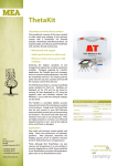
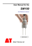
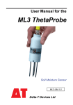
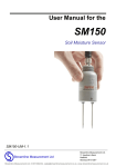
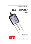
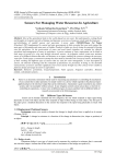
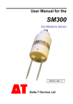
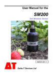
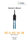
ThetaProbe
SOIL MOISTURE SENSOR
TYPE ML2x
USER MANUAL
ML2x-UM-1.21
Contents
Introduction & description .................................................................... 3
Installation .............................................................................................. 4
Wiring connections ................................................................................ 6
Connection to Delta-T data loggers (DL2 & DL3000) .......................... 7
Mechanical and electrical specifications ............................................. 8
Use and calibration ................................................................................ 9
Salinity .................................................................................................. 16
Compatibility with ThetaProbe, type ML1 .......................................... 17
Definitions............................................................................................. 20
References............................................................................................ 21
Guarantee, repairs and spares............................................................ 22
Patents
The ThetaProbe has been jointly developed by The Macaulay Land Use Research
Institute and Delta-T Devices and uses novel measurement techniques. They are
subject to the following patents:
UK - 2300485
Europe - 963703190.1
USA - 08\706675
Copyright
Copyright
1999 Delta-T Devices Ltd., 128 Low Road, Burwell, Cambridge, CB5
0EJ, England. All rights reserved. Under the copyright laws this book may not be
copied, in whole or in part, without the written consent of Delta-T Devices Ltd. Under
the law, copying includes translation into another language.
Delta-T Devices Ltd
128 Low Road, Burwell,
Cambridge CB5 0EJ, England
Telephone
: (01638) 742922
Fax
: (01638) 743155
E-mail
: delta-t.co.uk
ML2x-UM-1.21 May 1999
Page
2
Introduction & description
The ThetaProbe measures volumetric soil moisture content, θv, by the well
established method of responding to changes in the apparent dielectric constant. These
changes are converted into a DC voltage, virtually proportional to soil moisture content
over a wide working range.
Volumetric soil moisture content is the ratio between the volume of water present and
the total volume of the sample. This is a dimensionless parameter, expressed either as a
percentage (%vol), or a ratio (m3.m-3). Thus 0.0 m3.m-3 corresponds to a completely dry
soil, and pure water gives a reading of 1.0 m3.m-3. There are important differences
between volumetric and gravimetric soil moisture contents. The section on Definitions
gives details of the relationship between these two parameters and soil matric potential
(as measured by Tensiometers).
Operating principles
ThetaProbe consists of a waterproof housing which contains the electronics, and,
attached to it at one end, four sharpened stainless steel rods that are inserted into the
soil.
The probe generates a 100 MHz sinusoidal signal which is applied to a specially
designed internal transmission line that extends into the soil by means of the array of
four rods. The impedance of this array varies with the impedance of the soil, which has
two components - the apparent dielectric constant and the ionic conductivity.
The 100 MHz signal frequency has been chosen to minimise the effect of ionic
conductivity, so that changes in the transmission line impedance are dependent almost
solely on the soil's apparent dielectric constant. Because the dielectric of water (~81) is
very much higher than soil (typically 3 to 5) and air (1), the dielectric constant of soil is
determined primarily by its water content.
The impedance of the rod array affects the reflection of the 100 MHz signal, and these
reflections combine with the applied signal to form a voltage standing wave along the
transmission line. The output of the ThetaProbe is an analogue voltage proportional to
the difference in amplitude of this standing wave at two points, and this forms a
sensitive and precise measure of soil water content.
Work published over many years by Whalley, White, Knight Zegelin and Topp and
others, shows almost linear correlation between the square root of the dielectric
constant, ( √ε ), and volumetric moisture content, (θv), and this has been documented for
many soil types.
Each ThetaProbe is adjusted during manufacture to provide a consistent output when
measuring media of known dielectric constant, making them readily interchangeable
without system re-calibration.
The output signal is 0 to1V DC for a range of soil dielectric constant, ε, between 1 and
32, which corresponds to approximately 0.5 m3.m-3 volumetric soil moisture content for
mineral soils.
Page
3
ML2x-UM-1.21 May 1999
Installation
Essentially installation is very simple - you just push the probe into the soil until the
rods are fully covered, connect up the power supply and take readings from the
analogue output. Optional extension tubes are available for monitoring a soil layer
below the surface. However, it is quite possible to get sampling errors greater than 0.1
m3.m-3, and in extreme cases damage the probe if you don't pay due care and attention to
the details of the installation of ThetaProbes when making measurements of soil water
content.
You will need to consider each of the following factors when setting up a measurement:
Air pockets
The ThetaProbe is sensitive to the water content of the soil sample held within its array
of 4 stainless steel rods, but this sensitivity is biased towards the central rod and falls
off towards the outside of this cylindrical sampling volume. The presence of air
pockets around the rods, particularly around the central rod, will reduce the value of soil
moisture content measured. In particular, you need to be very careful when removing
and re-inserting the probe into a previous location.
Insertion angle
If the probe is going to be left in situ, and measurements taken during and after rainfall,
it is a good idea to insert it at an angle (say 20°), so that any water running down the
side of the probe housing tends to be carried away from the rods. This is particularly
important if the probe is being installed below the soil surface using a probe extension
tube.
Soil sampling points
The soil water content measured by a ThetaProbe within one small locality can be
affected by :
Variations in soil density and composition,
Stones close to the rods,
Roots (either nearby or pierced by the rods),
Earth worm holes (or even mole holes!),
Subsoil drainage,
Small scale variability in transpiration and evaporation losses.
It is important to take the degree of variability of these various parameters into account
when deciding on the number of probes to use at any particular location. If the soil is
known to be very heterogeneous, it will be necessary to take measurements from at least
three closely-spaced locations.
Care and maintenance
ThetaProbes are sealed after calibration, require no routine maintenance and are
constructed of materials selected for robust field operation. However, please pay
careful attention to the following 3 points:
1. Do not remove the cross-head sealing screws. This may damage the seal and will
invalidate your guarantee. No internal maintenance or repair can be performed by the
user.
2. Do not remove the ThetaProbe from soil by pulling on the cable.
ML2x-UM-1.21 May 1999
Page
4
If the measurement rods become bent in use, they can be carefully unscrewed from the
body and straightened. They have a right-handed thread.
3. Do not attempt to straighten the measurement rods while they are still attached to
the probe body. This may break the rods or damage the case seal.
Even a small degree of bending in the rods (>1mm out of parallel), although not enough
to affect the inherent ThetaProbe accuracy, will increase the likelihood of air pockets
around the rods during insertion, and so should be avoided. Replacements rods are
available if required (type ML-RODS). Ensure that they are fully tightened on reassembly, but do not apply excessive force, as this will cause damage to the probe body
seal.
Pre-preparation of holes to accept ThetaProbe measuring rods is recommended in stony
soils or other hard materials.
Extension tubes.
The probe is designed to be permanently buried, if required. When used like this,
optional extension tubes can be fitted to enable easier withdrawal, and to protect the
cable from damage by animals, etc.
Extension tubes are lengths of the same tubing as is used to make the ThetaProbe
cylindrical body. They have a female thread in one end and the same sized male thread
in the other.
Two lengths are available. ML/EX50 is 50cms long and ML/EX100 is 100cms long.
These can be screwed into each other to make longer lengths, as required.
Extension tubes allow the ThetaProbe to be lowered into pre-augured holes down to the
desired measurement depth, and to ease removal from the soil when the application
requires burial.
The outside diameter of the extension tubes is 4cms, so an auger of approximately 5cms
is recommended.
Extension tubes can be easily added to the ThetaProbe by following these instructions:
Carefully remove the black plastic, thread protection cover from the ThetaProbe. This
cover protects the extension tube mating thread when extension tubes are not needed. It
can be removed by sliding it up the cable.
Pass the ThetaProbe cable through the hole in the extension tube, ensuring that the
female thread in the extension tube is towards ThetaProbe. Screw the extension tube
onto ThetaProbe and hand tighten only. Repeat this process for additional extension
tubes to make up the length required.
Finally, thread the cable through the black plastic thread protection cover and slide the
cover into place over the male thread on the end of the extension tube. This will
minimise water ingress into the tube.
Page
5
ML2x-UM-1.21 May 1999
Wiring connections
ThetaProbe is supplied with a four core, screened cable which provides these
connections:
Red
Power supply positive.
Blue
Power supply zero volts.
Yellow
Output signal HI, load resistance 10KΩ minimum.
Green
Output signal LO.
Braid
Cable screen. Not connected within probe.
The Blue and Green leads are connected internally.
The braid screen should be connected to an analogue earth on the logger or other
measuring unit. If not using Delta-T equipment, please refer to the manufacturer's
instructions.
Some ThetaProbe variants have or require a connector to be fitted to mate to
appropriate Delta-T instrumentation. Connection details are given in the relevant
instrumentation User Manual.
Electromagnetic Compatibility ( EMC )
ThetaProbe has been assessed for compatibility under the European Union EMC
Directive 89/336/EEC and conforms to the appropriate standards, provided the moisture
measuring rods and probe body are completely immersed in the soil or other material
being measured. The cable connecting the ThetaProbe to its associated instrumentation
should also be routed along the surface of the soil.
If the probe is not installed in this way, some interference may be experienced on
nearby radio equipment. Under most conditions, moving the equipment further from
ThetaProbe (typically 1-2 metres) will stop the interference.
ThetaProbes installed near to each other will not malfunction due to interference.
ML2x-UM-1.21 May 1999
Page
6
Connection to Delta-T data loggers (DL2 & DL3000)
Power Connections
ThetaProbe can be directly powered by Delta-T data loggers using their internal
batteries. However, if several probes are to be used, or if the logger has to supply
significant power to other sensors or accessories, we recommend powering the logger
and sensors from an external power supply.
Battery power consumed by a probe for a single measurement taken with a 1 second
warm-up time is typically: 19mA * 1s ≅ 0.005 mA.h
Delta-T loggers include a minimum of two relay controlled outputs to provide and
control sensor power. Each relay ( called a warm-up relay ) is capable of switching 1A.
This means that each relay can typically power 50 ThetaProbes.
Configuring the Warm-up Channel
Although the probe can be continuously powered and read, significant power can be
saved by using the Delta-T logger warm-up relay facility to energise the sensor only just
before and during a log.
For complete stability, a warm-up time of 5s is recommended, although good
repeatability can be achieved using times down to 1s (the additional error associated
with a 1 second warm-up is only ±0.0025 m3.m-3). Shorter times will significantly
reduce the battery power consumption of the system.
Logger input channel configuration
ThetaProbe has been designed to make its use with dataloggers straightforward, using
only a single logger analogue input channel.
If you simply want to log the probe voltage directly, it should be treated as a differential
voltage source of range 0-1.5VDC, and the logger should be configured accordingly.
You can convert the data to soil moisture units after logging, using the information
supplied in the Calibration section.
The Calibration section also describes how to program your datalogger to
automatically convert probe output into soil moisture units before logging.
DL2e connection and configuration
This diagram shows the connections for a
ThetaProbe connected to channel 1 of a DL2e
in differential mode, and powered through the
loggers internal power supply. Further details
can be found in the SENSORS.TXT file which
is supplied with the DL2e sensor library codes
for the ThetaProbe, and in the DL2e manual
section on Relay Channels.
Two sensor configuration codes are supplied
with the DL2e: M2M which provides
generalised conversion from mVolts to
volumetric soil water content (in m3.m-3) suitable for generalised mineral soils, and
M2O, which is suitable for generalised organic soils.
DL3000 connection and configuration
Full details, including example connection diagrams, are available in the on-line Help
provided with Acquire!.
Page
7
ML2x-UM-1.21 May 1999
Mechanical and electrical specifications
(dimensions in mm)
Technical Specifications
Type No.
ML2x
Measurement parameter
Volumetric soil moisture content, θV (m3.m-3 or %vol.).
Range
Accuracy figures apply from 0.05 to 0.6 m3.m-3,
Full range is from 0.0 to 1.0 m3.m-3
Accuracy
±0.01 m3.m-3, 0 to 40°C,
±0.02 m .m , 40 to 70°C,
3
-3
after calibration to a
specific soil type
subject to soil salinity
errors, see below
±0.05 m3.m-3, 0 to 70°C
Soil salinity errors
0.0 to 250 mS.m-1, < -0.0001 m3.m-3 change per mS.m-1,
using the supplied soil
calibration, in all 'normal'
soils,
250 to 2000 mS.m-1, no significant change.
Soil sampling volume
>95% influence within cylinder of 4.0cm diam., 6cm long,
(approx 75 cm3 ), surrounding central rod.
Environment
Will withstand burial in wide ranging soil types or water for
long periods without malfunction or corrosion (IP68 to 5m)
Stabilization time
1 to 5 sec. from power-up, depending on accuracy required.
Response time
Less than 0.5 sec. to 99% of change.
Duty cycle
100 % ( Continuous operation possible ).
Interface
Input requirements: 5-15V DC unregulated.
Current consumption: 19mA typical, 23mA max.
Output signal: approx. 0-1V DC for 0-0.5m3m-3
Case material
PVC
Rod material
Stainless steel
Cable length
Standard: 5m.
Weight
350 gm approx. with 5m cable.
ML2x-UM-1.21 May 1999
Maximum length: 100m
Page
8
Use and calibration
ThetaProbe can be used to provide an instantaneous reading of soil conditions or, in
conjunction with a datalogger, comprehensive moisture data over time.
The millivolt output from the probe, although requiring a non-linear conversion to soil
moisture units for optimum accuracy, can provide reasonable results using a
straightforward linear conversion.
To use the probe without a datalogger, you will need to provide it with 5-15VDC at
about 20mA. Voltage readings can be taken with any general purpose voltmeter and the
conversion to soil moisture units made using the information given in a later section.
This measurement method produces good, instantaneous results easily, but for optimum
accuracy, automatic conversion to soil moisture units for known types of soil and, of
course, permanent data records, ThetaProbe should be used with a datalogger.
Data conversion methods
Every ThetaProbe uses the same characteristic to convert from its mV output to the
square root of the apparent dielectric constant,√ε, of the soil. However, the conversion
from √ε to percent moisture content depends on the soil type encountered. If you want
to log data in soil moisture content units, you will have to provide the logger with
information about how to convert the data.
Three main methods of configuring dataloggers to ThetaProbe are recommended:
• Polynomial equation conversion.
• Linearisation table conversion.
• Slope and offset conversion.
Each method is described in the following section.
The need for calibration
The relationship beween ThetaProbe output and soil moisture content is a non-linear
curve of this form:
θ v for generalised mineral and organic soils
1.000
0.900
organic
mineral
soil moisture (m3.m-3)
0.800
0.700
0.600
0.500
0.400
0.300
0.200
0.100
0.000
0
0.2
0.4
0.6
0.8
1
1.2
ThetaProbe output (V)
Page
9
ML2x-UM-1.21 May 1999
These two curves are generalised examples for mineral and organic soils. The
calibration curve for any specific soil would be slightly different from either of these
because the ThetaProbe is actually sensing the dielectric constant, (ε) of the soil, and
the relationship between the measured dielectric constant of a soil and its water content
(θ) depends on the particular composition of the soil.
You will need to calibrate the ThetaProbe for your specific soil if you want to minimise
the errors associated with converting the ThetaProbe output (V) to soil water content.
The repeatability of the ML2x is ±0.01 m3.m-3 (from 0 to 40°C) . Theoretically, if a soil
specific calibration is performed with no additional errors, this will be the probe error
in this situation. If using a generalised calibration, typical errors of ±0.05 m3.m-3
should be expected. In practice, whether you need to do a soil-specific calibration will
depend on what accuracy you need to work to and the size of your sampling errors (see
section on “Achievable Accuracy”).
Response to dielectric constant
Performing a soil-specific calibration is relatively straightforward, because all ML2x
ThetaProbes respond to dielectric constant in the same stable, uniform way, so it is
only necessary to do this once for one probe.
The relationship beween ThetaProbe output, (V), and square root of dieletric constant,
(√ε), is like this:
6.00
5.00
√ε
4.00
√ε
3.00
polynomial
linear
2.00
1.00
0.00
0
0.1
0.2
0.3
0.4
0.5
0.6
0.7
0.8
0.9
1
ThetaProbe output (V)
In the range 0 to 1 Volt (corresponding to a soil moisture range 0 to ~ 0.55 by volume),
this relationship can be fitted very precisely by a 3rd order polynomial:
ε = 1.07 + 6.4V − 6.4V 2 + 4.7V 3
(R2 = 0.998)
[1]
(R2 = 0.99)
[2]
or by the linear relationship:
ε = 11
. + 4.44V
ML2x-UM-1.21 May 1999
Page
10
Our experience of measurements on soils suggests that below 0.5 m3.m-3 there is no
significant improvement to the overall accuracy to be achieved by using the 3rd order
polynomial equation rather than the linear relationship.
For very high moisture contents (θ > 0.5 m3.m-3), the polynomial equation should be
used. This is usually only necessary for organic soils.
Soil-specific Calibration
Whalley, and White, Knight, Zeggelin and Topp have shown that there is a simple
linear relationship beween the complex refractive index (which is equivalent to √ε), and
volumetric water content, θ, of the form:
ε = a 0 + a1 ⋅ θ
[3]
Since the relationship beween ThetaProbe output and √ε is already known, it is only
necessary to determine the two coefficients, a0 and a1. We suggest you use the
following protocol:
Step 1
Collect a sample of damp soil, disturbing it as little as possible so that it is
at the same density as in situ.
Insert the ThetaProbe into the sample and measure the probe output, Vw.
εw .
Use equation [1] or [2] to calculate
Weigh the damp sample, (Ww), and measure its volume (L).
Step 2
Oven-dry the sample, insert the ThetaProbe into the dry soil (θ ≈ 0), and
measure the probe output, V0.
Weigh the dry sample, (W0). Use equation [1] or [2] to calculate
This equals a0. It will usually have a value between 1.0 and 2.0.
Step 3
ε 0.
Calculate the volumetric water content θ w of the original sample:
θw =
Step 4
Then
(Ww − W0 )
L
εw − ε0
.
θw
a1 =
[4]
It will usually have a value between 7.6 and 8.6.
Step 5
By inverting equation [3], and substituting from equation [2], the water
content determined from a calibrated ThetaProbe will then be:
θ=
[11. + 4.44V ] − a 0
[5]
a1
The corresponding equation using the polynomial relationship is:
[1.07 + 6.4V − 6.4V
θ=
a1
Page
11
2
]
+ 4.7V 3 − a 0
[6]
ML2x-UM-1.21 May 1999
Using this relationship (rather than the linear form) will enable the ThetaProbe to
achieve full accuracy over the full specified range, particularly for wetter soils with 0.5
< θ < 0.6.
Example:
1. In a sample of moist soil, the ThetaProbe gives an output of 0.43 V. This sample
weighs 1.18, and has a volume of 0.75 litres. From equation [1],
ε w = 3.01
2. After drying the sample of soil, the ThetaProbe gives an output of 0.11 V. From
equation [1] again, we can calculate a0 = ε 0 = 1.59.
3. The dry sample now weighs 1.05 kg, so the volume of water in the moist sample was
0.13 litres. Volumetric water content of the sample θ w = 0.173 m3.m-3.
4. By substituting in equation [4], a1 = 8.19
5. Finally, by inserting into equation [5], θ V = 0.54V - 0.060 m3.m-3
Note: It is important to use either the polynomial relationships (equations [1] and
[6]), or the linear relationships (equations [2] and [5]) consistently when deriving and
using the coefficients a0 and a1. In the above example the coefficients have been
derived using the linear relationship in equation [2], so equation [5] and not equation
[6], must be used for generating the conversion formula.
ML2x-UM-1.21 May 1999
Page
12
Generalised calibration
If it is not necessary to perform a soil-specific calibration, we suggest using the
following parameters which have been derived from the measurements taken on a large
number of mineral and organic soils:
a0
a1
Mineral
soils
1.6
8.4
Organic
soils
1.3
7.7
These parameters have been used to generate the following linearisation tables and
slope and offset conversions:
Linearisation table conversion
Delta-T dataloggers are able to store a linear or non-linear conversion characteristic
permanently in their software using a linearisation table. This enables almost
instantaneous logger channel configuration. All that is required is to select a Sensor
Type code number from a list displayed on your computer screen.
For users of existing Delta-T dataloggers, you can add the necessary linearisation tables
using the following data:
soil
moisture
θv, m3.m-3
-0.05
0
0.05
0.1
0.15
0.2
0.25
0.3
0.35
0.4
0.45
0.5
mV,
organic
soil
mV,
mineral
soil
-2090
40
110
192
283
400
500
600
700
780
850
920
-2090
90
170
280
400
510
620
720
810
880
940
1000
soil
moisture
θv, m3.m-3
0.55
0.6
0.65
0.7
0.75
0.8
0.85
0.9
0.95
1.0
1.05
mV,
organic
soil
mV,
mineral
soil
970
1010
1025
1045
1060
1070
1080
1090
1100
1110
2090
1020
1045
1055
1065
1070
1080
1085
1090
1100
1110
2090
For details of how to do this, refer to your Datalogger User Manual.
Use of this feature will give improved accuracy and give indicative moisture readings at
high moisture levels.
Note that non-linearity has been introduced at both ends of the table to avoid ‘out of
range’ logged readings outside of the probes valid working range.
Slope and offset conversion.
Using linear - fit equations from experimental data, offset and slope parameters have
been calculated that can be programmed into any data logger capable of accepting this
conversion method. For details of how to do this, refer to your data logger
Page
13
ML2x-UM-1.21 May 1999
documentation. Delta-T loggers can be programmed in this way if preferred, although
linearisation tables are capable of achieving higher accuracy.
For DL2 AND DL2e loggers, the ‘Engineering Factor’ used for slope conversion is
the reciprocal of the ‘Slope’ figures below.
This conversion method applies to a probe output range of 0-900mV, beyond which the
output becomes excessively non-linear.
The parameters to convert from probe output in mV to organic and mineral % moisture
content for soils are:
From probe mV to:
Slope
Offset
% moisture, Mineral
soil
0.050
-5.0
% moisture, Organic
soil
0.055
-2.0
Organic and Mineral definitions:
The generalised calibrations have been optimised to cover a wide range of soil types,
based on the following definitions:
Soil type
optimised
around organic
content:
use for organic
contents:
bulk density
range (g.cm-3):
use for bulk
densities
Mineral
~ 1 %C
< 7 %C
1.25 - 1.5 g.cm-3
> 1.0 g.cm-3
Organic
~ 40 %C
> 7 %C
0.2 - 0.7 g.cm-3
< 1.0 g.cm-3
ML2x-UM-1.21 May 1999
Page
14
Achievable accuracy
The errors associated with the ThetaProbe are shown in the Specifications table. They
are the errors associated with the instrument itself, and don’t take into account errors
you may introduce when carrying out a calibration, and they assume you insert the
probe perfectly into a perfectly uniform material. They assume an error budget like
this:
Error category
soilspecific
calibration
generalised
calibration
source of error
ThetaProbe errors
± 0.01
± 0.01
repeatability beween ML2x probes
Calibration errors
± 0.00
± 0.04
typical error in values of a0 and a1
Overall error
± 0.01
± 0.05
(RSS value)
In practice, when determining the overall reading errors, sampling and insertion errors
need to be considered. As described in the Installation section, these can be as large
as 0.1 m3.m-3. With care and by taking appropriate numbers of samples (10 to 20
samples might be required for each reading), you may reduce this, but unless your soil
is unusually homogeneous, these errors are unlikely to be less than 0.04 m3.m-3.
Based on that, you might expect the errors associated with your readings to look like
this example (values are m3.m-3):
Error category
soilspecific
calibration
generalised
calibration
source of error
ThetaProbe errors
± 0.01
± 0.01
repeatability beween ML2x probes
Calibration errors
± 0.02
± 0.04
errors in values of a0 and a1
Sampling errors
± 0.04
± 0.04
soil variability and insertion errors
Overall error
± 0.05
± 0.06
(RSS value)
If a linear, rather than Linearisation Table or polynomial conversion is used, the
following additional error will apply, resulting in the overall error shown.
Linearity errors
± 0.015
± 0.015
if linear rather than polynomial
conversion used (0 to 900mV)
Overall error
~ ± 0.05
~ ± 0.06
(RSS value)
It should be emphasised that these figures are given purely for illustration purposes - the
actual accuracy achieved in a particular measurement will depend mainly on
Page
15
•
soil heterogeneity,
•
the number of samples taken,
•
the extent to which it is possible to perform an accurate calibration on an
“undisturbed” sample,
•
inserting the ThetaProbe without causing air pockets or localised soil compression.
ML2x-UM-1.21 May 1999
Salinity
The output of the ThetaProbe is affected by the ionic conductivity of salts dissolved in
the soil moisture. This effect is not major, and is limited to salinity levels below about
250 mS.m-1. The potential error is discussed below.
Units
The preferred units for ionic conductivity units are mS.m-1 (where S is Siemens, a
measure of electric conductance).
The following conversions apply:
1 mS.m-1
= 0.01 mS.cm-1
= 0.001 mmho.cm-1
= 10 µS.cm-1
Soil salinity is also partitioned into the following descriptive categories:
0 - 200
mS.m-1
slightly saline
200 - 400
mS.m-1
moderately saline
400 - 800
mS.m-1
strongly saline
800 - 1600
mS.m-1
extremely saline
> 1600
mS.m-1
non-saline
ThetaProbe response
The ThetaProbe has been tested extensively in saline conditions, both in fluids and soils
(even up to 6000 mS.m-1!). The response in water of varying salinity is as follows:
MLURI conductivity data
1.2
ThetaProbe output (V)
1
0.8
Vmeasured
0.6
0.4
0.2
0
0
500
1000
1500
2000
2500
Ionic conductivity,==σ (mS.m )
-1
This response (in aqueous solutions) is accurately characterised by the following
equation:
V( σ =σ ′ ) =
V(σ =0 )
(1 + b0 (1 − e b1⋅σ ′ ))
, where b0 ≈ 0175
.
, and b1 ≈ −0.0038 , and σ is in mS.m-1.
[7]
The response to changes in salinity for soils (at fractional volumetric water contents less
than 0.6 m3.m-3) has been shown to be correspondingly less, but is difficult to quantify
ML2x-UM-1.21 May 1999
Page
16
accurately. We believe from the data available that the response curve follows the same
general shape, and that the values for b0 and b1 are similar.
Effect on the apparent soil moisture
There are two important simplifications to note as a result of the above response curve:
1. You can ignore salinity effects for soils that are known to be moderately saline
or strongly saline (i.e. 400 <=σ < 1600 mS.m-1) provided you have performed a
soil-specific calibration.
2. Changes in salinity due solely to drying/wetting cycles do not significantly affect
readings.
The worst case situation occurs when a non-saline soil is irrigated with saline
irrigation water, i.e when a calibration is carried out on a non-saline soil sample
(giving values for the coefficients a0 and a1, as in the previous section), but the actual
measurement is made on a sample with significant salinity.
As an indication of the size of the possible errors, we will assume that equation [7]
above is generally applicable to soils, and combine this with equations [2] and [3] to
give:
V =
a 0 + a1 .θ − 11
.
[
(
4.44 1 + b0 1 − e b1 ⋅σ
)]
[8]
For example, suppose a calibration has determined that the coefficients for a0 and a1
should be 1.5 and 7.8, and a reading of 0.71Volts is obtained with the ThetaProbe. If it
was assumed that the salinity was σ ′ = 0.0 mS.m-1, the soil moisture content calculated
from equation [8] would be θ ′ = 0.35 m3.m-3. However, if the sample’s salinity was in
fact σ ′′ = 100.0 mS.m-1, the real moisture content would have been θ ′′ = 0.37 m3.m-3,
resulting in an error of 0.02 m3.m-3.
Minimising errors due to salinity
Calibrate the ThetaProbe in a sample of soil which is towards the lower end of (but not
below) the range of salinities that are likely to be encountered.
If you are using the ThetaProbe in situations where the salinity varies widely and
includes non-saline conditions, you may need to measure the salinity and then apply a
correction using equation [8].
Compatibility with ThetaProbe, type ML1
Page
17
ML2x-UM-1.21 May 1999
ML2 output compared to ML1
6.00
5.00
√ε
4.00
3.00
ML1
ML2
2.00
1.00
0.00
0
0.1
0.2
0.3
0.4
0.5
0.6
0.7
0.8
0.9
1
output (V)
The ML2x performs very similarly to the previous version of the ThetaProbe, the ML1.
This graph shows a comparison of their response to dielectric constant.
These differences beween the ML1 and ML2x result in very slightly different values of
a0 and a1 when doing a soil-specific calibration (see below). When the differences in a0
and a1 are allowed for, the measurements of soil moisture can differ by up to 0.025
m3.m-3.
Adapting ML1 calibrations for ML2x
If you’ve done a soil specific calibration with the ML1, and generated values of a0(ML1)
and a1(ML1), those values should be unchanged when used with the ML2x, because they
describe the dielectric properties of the soil (see equation [3]), and are theoretically
independent of the response of the ThetaProbe. However the changes to the nature of
the curve (or linearisation) used to model the response of the ThetaProbe does have a
slight effect on the calculated values of a0 and a1, and so you may choose to use
slightly different values, a0(ML2) and a1(ML2), for the ML2x.
• for maximum
compatibility with
ML1 readings, use:
• for greatest accuracy
ML2x-UM-1.21 May 1999
mineral soils:
no change.
organic soils:
a 0( ML 2 ) = a 0( ML1) ,
a1( ML 2 ) = a1( ML1) − 01
.
generate new values of a0 and a1 using the ML2x and
following the procedure on page 11.
Page
18
Mixed installations of ML1 and ML2x ThetaProbes
If you have a mixture of ML1 and ML2x ThetaProbes in an installation, obviously the
best choice is to use ML1 calibrations for the ML1 and ML2x calibrations for the
ML2x.
Sometimes that will be impractical, and you need to know whether it’s possible to use
both ML2x and ML1 with the same conversion. If you do, there will be an extra source
of errors in the errors table, and the overall reading errors will typically increase by
0.01 m3.m-3, as in this rework of the example in the section on Acieveable Accuracy.
Error
category
soilspecific
calibration
generalised
calibration
source of error
ThetaProbe
errors
± 0.01
± 0.01
repeatability beween ML2x probes
compatibility
errors
± 0.025
± 0.025
max. differences beween ML2x and
ML1 probes (non-random error)
Calibration
errors
± 0.02
± 0.04
errors in values of a0 and a1
Sampling
errors
± 0.04
± 0.04
soil variability and insertion errors
Overall error
~ ± 0.06
~ ± 0.07
(RSS value)
Using the ML2x with the ThetaMeter, type HH1
The ThetaMeter is optimised for use with the ML1 rather than the ML2x. It is
compatible with the ML2x, and the mVolt readings will be accurate, but the mineral
and organic conversions use the old ML1 values for slope and offset. The effect of this
is to add approximately 0.01 m3.m-3 error to the readings, as in the example above. This
can probably be ignored for the general purpose use for which the ThetaMeter was
intended.
Page
19
ML2x-UM-1.21 May 1999
Definitions
Volumetric Soil Moisture Content is defined as
θV =
VW
VS
where Vw is the volume of water contained in the sample,
and Vs is the total volume of the soil sample.
The preferred units for this ratio are m3.m-3, though %vol is also frequently used.
The usefulness of this definition depends in part on the fact that the volume of the dry
soil does not change as water is added. This is not true of shrink-swell soils, but for the
most part is a reasonable approximation. Soil Moisture Content varies from approx.
0.02 m3.m-3 for sandy soils at the permanent wilting point, through approx. 0.5 m3.m-3
for clay soils at their field capacity, up to values as high as 0.85 m3.m-3 in saturated peat
soils.
Soil water content is usually expressed volumetrically, because it is then possible to
ignore the bulk density of the soil sample.
Volumetric versus Gravimetric soil water content
Gravimetric Soil Moisture Content is defined as
θG =
MW
MS
g.g-1
where MW is the mass of water in the sample,
and M S is the total mass of the dry sample.
To convert from volumetric to gravimetric water content, use the equation
θ G = θV *
ρW
ρS
where ρW is the density of water (= 1),
and ρ S is the bulk density of the soil sample ( =
MS
).
VS
Soil Water Content versus Soil Matric Potential
Studies of plant growth need to characterise the availability of water to the plant, and
this is usually done using the soil matric potential, φw, which measures the suction
necessary to extract a unit voume of water from the soil pores, and is measured in units
of pressure, hPa. The soil matric potential is highly dependent on both soil type and soil
water content, and varies from 0 hPa at field capacity, down to approximately -1500
hPa at the permanent wilting point.
The relationship beween soil water content (θv) and soil matric potential (φw) is called
the water release curve (or characteristic, or retention curve), and varies greatly for
different soil types. There is no generalised method of converting from soil water
content to matric potential, though a number of expressions have been found which
have been successfully applied to a restricted list of soil types.
ML2x-UM-1.21 May 1999
Page
20
References
1.
Gaskin, G.J. and Miller, J.D. 1996
Measurement of soil water content using a simplified impedance measuring
technique.
J. Agr. Engng Res 63, 153-160
2.
Topp, G. C., J. L. Davis, A. P Annan 1980
Electromagnetic determination of soil water content
Water Resour. Res 16(3) 574-582
3.
Whalley, W R 1993
Considerations on the use of time-domain reflectometry (TDR) for measuring soil
moisture content.
Journal of Soil Sci. 44, 1-9
4.
White, I, Knight, J H, Zegelin, S J, and Topp, G C 1994
Comments on ‘Considerations on the use of time-domain reflectometry (TDR) for
measuring soil water content’ by W R Whalley
Journal of Soil Sci. 45, 503-508
5.
Roth, C H, Malicki, M A,and Plagge, R. 1992
Empirical evaluation of the relationship between soil dielectric constant and
volumetric water content as the basis for calibrating soil moisture measurements.
Journal of Soil Sci. 43, 1-13
6.
Page
21
Knight, J.H. 1992
Sensitivity of Time Domain Reflectometry measurements to lateral variations in
soil water content.
ML2x-UM-1.21 May 1999
Guarantee, repairs and spares
Our Conditions of Sale ref: COND/91/11 set out Delta-T's legal obligations on these
matters. For your information the following paragraphs summarise Delta-T's position
but reference should always be made to our Conditions of Sale which prevail over the
following explanation.
Instruments supplied by Delta-T are guaranteed for one year against defects in
manufacture or materials used. The guarantee does not cover damage through misuse or
inexpert servicing, or other circumstances beyond our control.
For the UK this means that no charges are made for labour, materials or return carriage
for guarantee repairs.
For other countries, the guarantee covers free exchange of faulty parts during the
guarantee period.
Alternatively, if the equipment is returned to us for guarantee repair, we make no charge
for labour or materials but we do charge for carriage and UK. customs clearance.
We strongly prefer to have such repairs discussed with us first, and if we agree that the
equipment does need to be returned, we may at our discretion waive these charges.
Service and spares
We recognise that some users of our instruments may not have easy access to
technically specialised backup. Please refer to the Care and Maintenance section of this
Manual for specific information on this product.
Spare parts for our own repairable instruments can be supplied from our works. These
can normally be despatched within 1 working day of receiving an order.
Spare parts and accessories for sensors not manufactured by Delta T, but supplied by us
individually or as part of the weather station or other system, may be obtained from the
original manufacturer. We will endeavour to obtain parts if requested, but a certain
amount of additional delay is inevitable.
Should it prove necessary, instruments may be returned to our works for servicing. We
normally expect to complete repairs of our own instruments within 2 days of receiving
the equipment. Other manufacturers' sensors supplied by us and returned for servicing
will take longer. They will have to be returned to the original manufacture for servicing,
and may be subject to additional delays of two to four weeks.
Users in countries that have a Delta-T Agent or Technical Representative should
contact them in the first instance.
ML2x-UM-1.21 May 1999
Page
22