1
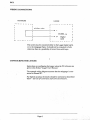
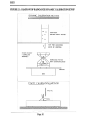
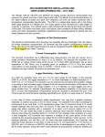
User Manual for the
Raingauge
type RG1
RG1-UM-3
DELTA-T DEVICES
ABOUT THIS MANUAL
This manual describes how to install and use the raingauge type
RGL
COPYRIGHT
Copyright O 1996 Delta-T Devices Ltd, 128 Low Road, Burwell,
Cambridge, CB5 OEJ, England. All rights reserved. Under the
copyright laws this book may not be copied in whole or in part
without the written consent of Delta-T Devices Ltd. Under the
law, copying includes translation into another language.
Revised: Jan 1996
I n this Manual, a11 references to loggers and weather stations
, software LS2, the WSOl
relate to the Delta-T Logger D L ~ its
Weather Station, and the sensor codes used with them. The
references also apply to the DL2E and its derivatives.
F o r use with the DL3000 logger, you must refer to the
DL3000 documentation. I t contains the specific connection
details and sensor type codes used by the DL3000. General
information concerning the performance and installation of
the sensor contained in this mama1 remains reIevant.
Page ii
Raingauge
Delta-T Serial Number :
RG1.
Sensor type code :RG1
Date
of last
calibration
Calibration
Factor
Correction
Factor
CONTENTS
INTRODUCTION
SITING THE RAINGAUGE
WIRING CONNECTIONS
CONFIGURING THE LOGGER
USE OF CONVERSION & CORRECTION
FACTORS
SPECIFICATION
CALIBRATION
REFERENCES
GLOSSARY
GUARANTEE, REPAIRS & SPARES
Page 3
INTRODUCTION
Conventionally shaped raingauges interfere with the airflow, so
that the catch is reduced. This raingauge was aerodynamically
designed by the Institute of Hydrology, and is very similar to that
derived theoretically and independently by the UK Meteorological
Office as an "ideal" shape.
The raingauge is fabricated in UV-resistant vacuum-formed plastic. It operates in the same way as any other tipping bucket raingauge. The water collected by the funnel is passed into a doublesided container which tips when a set amount of water has been
collected in one side, the process repeating indefinitely. At each
tip, the bucket causes a magnet to pass a magnetic reed switch,
closing its contact for a fraction of a second. This contact closure
is counted by the Delta-T Logger. The gauge is calibrated to tip
once for each 0.2 mm of rain. An individual calibration factor is
given for each raingauge.
Page 4
SITING THE RAINGAUGE
The gauge should be installed in accordance with the standard
rules applicable to any raingauge, such as ensuring that it is not
closer to an object by more than twice the object's height. This
avoids any shielding effect. The weather station mast has quite a
low wind profile, but we provide 5m of cable for mounting the
raingauge at a distance from the mast. Further information on
raingauge exposure is given in the publications listed at the end of
this section. Research has shown that since a raingauge acts as an
obstruction to the flow of wind, the flow of air speeds over the top,
causing less rain to be collected by the funnel than would have
fallen on the ground if the raingauge had not been there. In most
cases this is ignored, but it may be corrected for arithmetically, or
overcome physically by placing the gauge in a pit with the tip of its
funnel level with the ground. The pit is covered by a grating to
simulate the ground aerodynamically while preventing splash-in to
the funnel. While excellent, this method may not always be practical. To minimise the effect of wind turbulence around the funnel, the profile of the raingauge has been designed to reduce wind
effects so that the catch of the gauge is increased. Such a gauge
can, therefore, be deployed successfully in more exposed sites.
An anodised aluminium base plate is provided for levelling the
raingauge and to attach it firmly to the ground. This plate can
either be pinned to the ground with the stakes provided, or it can be
bolted to a bl~ckof concrete or wood.
Three threaded studs attached to the base plate are bolted to the
plastic base of the raingauge. It can be levelled by adjusting the
heights of the nuts on the studs and by observing the built-in spirit
level.
It is important to ensure that the raingauge is level. Failure to do
this will result in a systematic error. Many users pay only scant
attention to this, yet it is one of the simplest means of improving
the accuracy of rainfall measurements.
Page 5
WIRING CONNECTIONS
RAINGAUGE
- - a -
1
--
LOGGER
.
--
-----------
I
I
1
I
I
I
e i t h e r wire
I
I
-
L
l
I
The screen may be connected either to the Logger digital earth,
or to the raingauge frame. It should not be connected to both,
otherwise there is a,possibility of errors from earth loops.
CONFIGURING THE LOGGER
Instructions on configuring the logger using the PC software are
given in the Delta-T Logger User Manual.
>
The example wiring diagram assumes that the raingauge is connected to channel 61.
For highest accuracy the results should be corrected as described
below - see Use of Conversion and Correction Factors.
Page 6
USE OF CONVERSION AND CORRECTION FACTORS
Consider this example.
For a particular raingauge it is found that each tip corresponds to
0.198 mm of rain. This corresponds to a Conversion Factor of
110.198 = 5.051 tips per mm of rain.
When you programme the logger, and are defining a raingauge
sensor type, the logger will ask you what engineering units to use,
to which you reply "mm". It will then ask you the number of
counts per mm. The accurate Conversion Factor to use is, in this
example, 5.051 counts per mm. However the logger will not
accept a non-integer conversion factor for a counter input, thus
losing the potential high accuracy which can be achieved with this
type of calibration. This is a limitation in the software of the
logger. If you tell it 5.051 it will round the conversion factor to the
nearest integer value, ie 5. The only way to regain the accuracy
of the measured rainfall is to multiply the logged data by a
correction factor corresponding to the difference between the true
conversion factor and the rounded integer value used by the logger.
For example,
Given 1000 tips during a recording intcwal.
The calibration for a particular raingauge is 0.198 mm per tip,
ie 5.051 tips per mm.
The logger calculates 100015 = 200 mm of rain
The true value is 100015.051
or 1000 X 0.198 = 198 mm of rain
The correction factor to be applied is
This procedure acknowledges two things. Firstly that the user
probably does not have the time to adjust and test, adjust and test,
many times over to get the setting exactly on 0.2 mm per tip, nor to
repeat such a laborious procedure on a regular (say yearly) basis.
Secondly, the logger software cannot handle non-integer
conversion factors for the counter input channels. The processed
data printed out by the logger, or collected by your computer,
should be multiplied by the appropriate correction factor.
Page 7
SPECIFICATIONS
Sensitivity :
0.2 mm per tip ( nominal ).
Calibration :
Individual calibration factor provided.
Calibration limits :
0.195 to 0.205 mm per tip.
Accuracy :
No accepted standard'forcomparison.
Funnel diameter :
254 mm ( 10 inches ).
Overall height :
350 mm without baseplate and tripod.
Switch:
magnetic reed switch.
300 mA max current allowable
Output :
Contact closure at "tip".
Weight :
1.0 kg without base plate and tripod.
Levelling :
Tripod levelling mechanism with spirit level.
Mounting :
Anodised aluminium base plate pinned to the ground with 4
zinc-plated steel stakes. Alternatively the base plate can be
bolted to a block of concrete or to a heavy block of wood.
Cable :
6 m PVC, screened twisted pair.
Page 8
CALIBRATION PROCEDURES
Static Calibration
The raingauge is calibrated during manufacture as described
below. This may be repeated by the user if desired.
Install the raingauge, as illustrated in Figure 5.1, over a sink ensuring that it is level. Using a burette or pipette, adjust the two calibration screws under the tipping bucket until it tips with the correct
amount of water ( 10.13 cc for a 0.2 mm sensitivity). It will not
be possible to set the screws with very high precision in this way
but it should be done with as much care as possible. ( This stage
may be omitted if rechecking the calibration ). Only by means of
a dynamic test can the exact calibration of a tipping bucket ( of any
type ) be established. This test is described below. Many manufacturers and users of tipping bucket raingauges aim to adjust the
bucket settings until EXACTLY the correct calibration is obtained.
To achieve this, it would be necessary to repeat the dynamic test
many times over, and this is very time consuming. In any case, it
is almost impossible to get the adjustment absolutely correct.
Therefore, it isconsidered better practice by the Institute of Hydrology to adjust the settings as closely as is reasonably practical
and then to derive a Calibration Factor for each gauge.
The Calibration Factor can be found using the dynamic calibration
procedure described below.
.
Dynamic Calibration
When the static burette test described above has been done, the
calibration of the gauge should be checked as follows (most users
will Start from here). This procedure was carried out prior to
dispatch, and the resulting Calibration Factor written inside the
raingauge and at the front of this chapter.
Set up the calibration test as shown in Figure 5.1. Ensure that the
gauge is level. Connect the output wires to channel 61 or 62 of
the logger, or any convenient electronic or electromechanical
counter. Fill the container with 810.4 cc of water. This is done
most precisely by weighing the water on scales capable of measuring to 0.1 gm. If this is not practical, it should be done using a
good quality graduated measuring cylinder. Allow the water to drip
slowly into the gauge, taking at least 30 minutes to empty the
container. At the end of this period there should have been 80 tips.
It is unlikely, however, that there will be exactly this number.
Note how many tips actually occurred and also estimate as precisely as possible what fraction of a tip is left in the bucket. Only if the
adjustment has been very precise indeed will the bucket tip at the
moment the last drop passes into it. The Calibration Factor can
now be calculated.
Page 9
FIGURE 5.1 :DIAGRAM OF RAINGAUGE DYNAMIC CALIBRATION SET-UP
DYNAMIC CALIBRATION ME'rt-IOD
_
-.
CONTAINER
HOLDING 1OOOcc WATER
-
l
TAP FOli ADJUS'I'ING
RATE OF DRIPPING
ENSURE BUCKET
IS LEVELLED
PRECISELY
RAINGAUGE
WITI-1 COUNT
SINK
STATIC CALIBRATION METIi00
How to Calculate the Calibration Factor
Let N equal the number of tips. This should include an estimate
of the fraction of a tip left in the bucket, eg 0.5 of a tip. The
Calibration Factor is then :
For example, if N = 78.8, then
= 0.2 X 80178.8
= 0.203 mm per tip.
Provided the Conversion Factor lies between 0.195 and 0.205 mm,
or 78.0 and 82.1 tips, respectively, then it is acceptable for most
purposes. The gauge is calibrated at manufacture such that each
tip will lie within the above limits.
There is no reason, however, why users should not, if they so wish,
aim for closer agreement with the nominal tip of 0.2 mm by repeated adjustments of the calibration screws followed by further
dynamic tests. Only time limitations will set a limit to this.
Please refer to the appropriate section of the Delta Logger User
Manual for general instructions.
Page 11
REFERENCES
1.. Rodda, J.C.,(1967) "The rainfall measurement problem", Proc.
IAHS Gen. Ass., Bern, IAHS Pub. No. 78,215-231.
2. HMSO (1956) Handbook of Meteorological Instruments, Part 1
Met.0.577, published by Her Majesty's Stationery Office, U.K.
3. HMSO (1982) Observers Handbook, Met. 0.933, published by
Her Majesty's Stationery Office, U.K.
4. Hughes, C.? Strangeways, I. & Roberts, A.M.
Field Evaluahon of two aerodynamic raingauges.
Weather (1993) Vol48, No 3 66-71
GLOSSARY OF TERMS
Calibration Factor:
Defined by the raingauge manufacturer as
the number of mm of rain per tip.
eg 0.198 mdtip
Conversion Factor : The number of tips per mm of rain.
This is the reciprocal of the calibration factor, and is the figure the
logger software will ask for when defining a sensor type library.
The logger will round this to the nearest integer - 5.
Correction Factor : The number by which the output of the logger must be multiplied
in order to compensate for the integer conversion factor, and so
calculate the true rainfall.
= Calibration Factor X 5
eg 0.198 X 5 = 0.99
Page 12
GUARANTEE, REPAIRS AND SPARES
Our Conditions of Sale ref COND/91/11 set out Delta-T's legal obligations on these matters.
For your information the following paragraphs summarise Delta-T's position but reference
should always be made to our Conditions of Sale which prevail over the following
explanation.
Instruments manufactured by Delta-T are guaranteed for one year against defects in
manufacture or materials used. The guarantee does not cover damage through misuse or
inexpert servicing, or other circumstances beyond our control.
For the U.K. this means that no charges are made for labour, materials or return carriage for
guarantee repairs.
For other countries, the guarantee covers free exchange of faulty parts during the guarantee
period.
Alternatively, if the equipment is returned to us for guarantee repair, we make no charge for
labour or materials but we do charge for carriage and U.K. customs clearance.
We strongly prefer to have such repairs discussed with us first, and if we agree that the
equipment does need to be geturned, we may at our discretion waive these charges.
SERVICE AND SPARES
We recognise that some users of our instruments may not have easy access to technically
specialised backup.
Spare parts for our own instruments can be supplied from our works. These can normally be
despatched within 1 working day of receiving an order.
Spare parts and accessories for sensors not manufactured by Delta T, but supplied as part of
the weather station, may be obtained from the original manufacturer. We will endeavour to
obtain parts if requested, but a certain amount of additional delay is inevitable.
Should it prove necessary, instruments may be returned to our works for servicing. We
normally expect to complete repairs of our own instruments within 2 days of receiving the
equipment. Other manufacturers' sensors supplied by us and returned for servicing will take
longer. They will have to be returned to the original manufacturer for servicing, and may be
subject to additional delays of two to four weeks.
Users in countries which have a Delta-T Agent or Technical Representative should contact
them in the first instance.