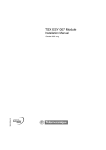
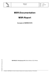
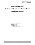
1
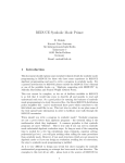
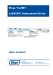
Modicon Premium PLCs
TSX SAY 100
AS-i Bus Interface Module
Module interface bus AS-i
Quick reference guide
Instruction de service
Edition September 2004
TSX SAY 100
• Preface
This document is only concerned with the hardware installation of the TSX SAY 100 AS-i bus
master module, from a Premium PLC (TSX 57, PMX 57, PCX 57, PCI 57). For the complete
installation of an AS-i bus, the following documents should be consulted :
- the AS-i bus reference manual : XDOC 5511E (design and installation of the bus)
- the application-specific manuals : TLX DS 57 PL7 30E (software setup)
- the AS-i bus user manual using Unity Pro : 35006197.
• Summary of the AS-i bus
The AS-i bus is a level 0 fieldbus which can be used to connect sensors/actuators. It is used for
the communication of discrete data between a bus master and sensor/actuator "slaves".
AS-i comprises three main elements :
- a specific power supply providing a voltage of 30 VDC (TSX SUP A02/A05)
- a bus master (TSX SAY 100 module)
- a number of slaves (communicating sensors / actuators and/or IP20/IP65 interfaces)
Example of an AS-i bus topology from a TSX 57 PLC
TSX 57
Level 1
TSX SAY 100
AS-i master
Level 0
AS-i power
supply
Communicating sensors/
actuators
Interfaces
Traditional sensors/
actuators
1
ENGLISH
Introduction
TSX SAY 100
ENGLISH
Physical presentation
1 Display block comprising 4
status indicator lamps for
displaying the module operating
modes:
- greenRUN indicator lamp: on
during normal operation of the
module.
1
- redERR indicator lamp: on, it
indicates a module fault.
2
- greenCOM indicator lamp: on,
3
it indicates data exchanges
4
on the AS-i medium.
5
- red I/O indicator lamp: on, it
6
indicates an external I/O fault
7
on the AS-i bus
2 Display block comprising 32
indicator lamps (0 to 31) for diagnostics of the AS-i bus and
8
displaying the state of each
slave connected on the bus.
3 Red AS-i indicator lamp: on, it
indicates a fault on the
AS-i power supply.
4 Green BUS indicator lamp: on, it indicates that display block 2 is in BUS display mode (displaying
the slaves on the bus).
5 Green I/O indicator lamp: on, it indicates that display block 2 is in slave "SLV" display mode
(display of the I/O bits of the selected slave).
↑↓
6 Pushbutton "↑↓
↑↓" dedicated to local diagnostics of the AS-i bus. Pressing this pushbutton (long
or short presses), combined with the "+/–" pushbutton enables the user to move between the
various AS-i bus diagnostic modes.
7 Pushbutton "+/–" dedicated to local diagnostics of the AS-i bus. Pressing this pushbutton (long
↑↓
or short presses), combined with the "↑↓
↑↓" pushbutton enables the user to move between the
various AS-i bus diagnostic modes.
8 CANNON SUB D connector for connection to the AS-i bus.
2
TSX SAY 100
ENGLISH
Mounting/Installation
The TSX SAY 100 module can be mounted in any position
in a TSX RKY rack, except for the positions specifically for
the power supply and the processor.
The insertion and removal of this module follows the
general procedure for inserting and removing modules on
Premium PLCs (see installation manual for Premium
PLCs).
The module can be inserted and removed with the PLC power
supply and the AS-i bus power supply on.
The number of modules per PLC station depends on the
type of processor installed:
•
•
•
•
•
TSX P57 0244processor
: 1 module maximum
TSX/TPMXP57102,1i4,1634 , TPCX 57 1012processors
: 2 modules maximum
TSX/TPMXP572i 2, 2i 4, , 2634, PCI57 204 processors
: 4 modules maximum
TSX/TPMXP573i2, 3i4, 3634, TPCX 57 3512, PCI 57 354 processors : 8 modules maximum
TSX/TPMXP574i 2, 454, 4634, 554, 5634 processors
: 8 modules maximum
Connections
• AS-i bus cable
This carries signals and provides the sensors and actuators connected
on the bus with a 30 VDC supply.
- AS-i ribbon cable, shaped to prevent incorrect insertion :
yellow, wire cross-section 1.5 mm2
- standard round cable with 1.5 mm2 or 2.5 mm2 cross-section wires.
recommended cable : reference H05VV-F2x1.5 complying with standard DIN VDE 0281. Wire cross-section 1.5 mm2.
AS-i –
AS-i +
(Blue)
(Brown)
AS-i –
AS-i +
(Blue)
(Brown)
• Cablerouting
- The AS-i cable must be kept away from high energy power cables. To do this, the AS-i cable and
the power cables must be in separate ducting and protected from one another by a metal screen
- When the AS-i cable is routed together with the control cables, it is essential that the connections
on these control links are made in accordance with standard practice (discharge diode or peak
limiters on the terminals of inductive elements, etc)
• Connection of the module to the AS-i bus
A kit (connector + cover) is supplied with the
module for connecting it to the AS-i bus.
This connector must be connected to the
AS-i bus cable and assembled by the user in
accordance with the steps described on the
next page.
Connector
cover
3
ENGLISH
TSX SAY 100
1 Connect the 2 wires of the AS-i cable to the
connector observing the polarities
brown wire
2 Insert the connector in its cover and secure the
cable to the cover
Note: if in
exceptional
circumstances a
shielded cable is
used, this should be
connected to the
central terminal
blue wire
4 Mount the assembled unit on the module
3 Close the cover by snapping it shut
Displaying the module status
The 4 indicator lamps (RUN, ERR, COM and I/O) located on the front panel of the module inform the
user of the operating status of the module and the bus.
Status
On
Flashing
Off
Indic.
RUN
Module operating
Module self-test (1)
Module faulty or
(green) normally
module off
ERR
Serious internal fault,
Module self-test (1)
No internal fault
(red)
module failure
Application faulty, or
fault on AS-i bus
COM
–
Module self-test (1)
No communication
(green)
Communication on the
on the AS-i bus
AS-i bus
I/O
I/O fault
Module self-tests (1)
Module operating
(red)
normally
(1) all 4 indicator lamps flash simultaneously during the self-tests when the module is powered up.
4
TSX SAY 100
ENGLISH
Special displays of the TSX SAY 100 module
3 indicator lamps : AS-i, BUS and I/O display data specific to the
TSX SAY 100 module.
AS-i
• AS-i indicator lamp
Indicator lamp off: normal operation of the module
Indicator lamp on: Power supply fault on the AS-i bus
Indicator lamp flashing: automatic addressing initialized
• BUS and I/O indicator lamps
These two indicator lamps show the selected display mode:
- BUS display mode or
- slave display mode.
Module display
SLV BUS indic.
On
@ I/O indic.
Off
Diagnostics
The 32 indicator lamp
display block on the
front panel of the module
is in Bus display mode
which shows the slaves
present on the bus.
Off
On
Off
Off
The 32 indicator lamp
display block on the
front panel of the module
is in slave (SLV) display
mode with the status of
the I/O bits of the
selected slave displayed.
The 32 indicator lamp
display block on the front
panel of the module is
in slave (SLV) display
mode with the address
of the selected slave
displayed.
5
TSX SAY 100
ENGLISH
Characteristics
AS-i bus
TSX
SAY 100
module
AS-i bus maximum cycle time
Maximum number of slaves on the AS-i bus
Maximum length of the AS-i bus
(including all branches without repeater)
Maximum number of I/O
AS-i bus nominal supply voltage
Programming the module
Program response time with 31 slaves
for a PLC scan time of 10 ms (1)
Current drawn on the internal 5V
Current drawn on the AS-i 30 V
AS-i master profile
Operating temperature
5 ms
31
100 meters
124 inputs + 124 outputs
30 VDC
using the PL7 Junior
/Pro and Unity Pro software
typically 27 ms
maximum 37 ms
110 mA typical/150 mA max.
50 mA typical/60 mA max.
M2
0 to 60°C (without ventilation)
(1) Time between an AS-i input activated on the bus, processed in the PLC application and applied
to an AS-i output
Safety of personnel
To ensure the safety of personnel, it is essential to:
• connect the PLC ground terminal to earth
• use a SELV (very low safety voltage) AS-i power supply, with 30 VDC nominal voltage
• for PLCs connected to an AC supply, place a residual current device upstream of this supply which
will disconnect the PLC power supply source if an earth leakage is detected
• for PLCs connected to an AC supply, ensure that the power supply placed upstream of the PLC is
SELV
• use AS-i certified products on the bus
Because of its technology and connections, the AS-i TSX SAY 100 module only takes 5 VDC, and
its electrical 0 V is connected to the PLC ground.
6
TSX SAY 100
The AS-i bus is managed by channel 0 of the TSX SAY 100 module. The syntax of the I/O data is
as follows:
Inputs
%I\xy.0\n.i
x = rack address (0 to 7)
Outputs
%Q\xy.0\n.i
y = module address in the rack (0 to 10)
n = number of the slave on the AS-i bus (1 to 31)
i = number of the slave input or output bit (0 to 3)
Addressing I/O objects using Unity Pro
The AS-i bus is managed by channel 0 of the TSX SAY 100 module. The syntax of the I/O data is
as follows:
Inputs
%I\b.e\r.m.c
b = bus number (2 to 999)
Outputs
%Q\b.e\r.m.c
e = number of the slave on the AS-i bus (1 to 31)
r = virtual rack address (0)
m = virtual module address (0)
c = number of the slave input or output bit (0 to 3)
7
ENGLISH
Addressing I/O objectsusing PL7
TSX SAY 100
ENGLISH
Operating modes of the TSX SAY 100 module
• Fallbackposition
The fallback mode of the outputs is defined in the configuration screen and can be read :
- in word using PL7 (%KWxy.0.19:X0=1 : fallback to 0, %KWxy.0.19:X0=0 : maintain state). See
the application-specific installation manual "AS-i application specific function".
x = rack address, y = module address.
- in word using Unity Pro (%KWr.m.0.19.0=1 : fallback to 0, %KWr.m.0.19.0=0 : maintain state). See
AS-i bus user manual using Unity Pro.
x = rack address, y = module address.
Behavior when the AS-i channel changes to STOP:
- with the reset to 0 option: the outputs are forced to 0, then the communication on the medium stops,
- with the maintain state option: the state of the outputs is maintained, then the communication on
the medium stops,
• Automatic addressing of slaves
When this function is validated in the module configuration, a faulty slave can be replaced by a
slave of the same type without stopping the AS-i bus and without the necessity for any special
operation.
If the replacement slave is programmed with the same address and it has the same profile, it will
be automatically inserted in the list of slaves which are detected and activated. If this is not the
case, the ERR and AS-i indicator lamps flash simultaneously.
If the new slave is unformatted (address 0, new slave) and it has the same profile, the slave will
automatically take the address of the slave which it replaces and will therefore appear in the list
of slaves which are detected and activated. If this is not the case, the ERR and AS-i indicator lamps
flash simultaneously. These operations are only possible if a single slave in the configuration is
faulty.
• Processor fault
If communication with the processor is broken, the module switches to safety position. Causes of
the communication break:
- tripping of the processor watchdog if the module is located in the rack containing the processor.
- disconnection of the bus X cable if the module is located in an extension rack.
• Modulefault
If there is a serious module fault (faulty component, etc), the module stops the communication with
bus X and with the AS-i bus. The same behavior occurs as when a module is removed while
powered up.
• Removing the module while it is powered up
Communication with bus X stops, the processor indicates a module fault. Communication on the
AS-i bus is also interrupted without warning. In this case, the slaves which have a watchdog set
their outputs to the required state and the others remain in the same position and cannot be set to
0 because the module can no longer provide communication.
8
• Inserting a module with the power on
After powering up the module, it waits to receive the configuration from the processor or for one of
the "↑↓"or "+ / –" pushbuttons to be pressed, otherwise it remains stopped.
• Fault on the AS-i power supply (shown by the AS-i indicator lamp being on)
When there is an AS-i power supply fault, the communication stops and :
- the outputs of slaves which have a watchdog are set to the required state, unless the slave draws
its power on the AS-i medium
- the commands of the slaves change to 0 as a result of loss of power
• Breaking of the AS-i medium
There are several possibilities:
- the medium is cut at the module output: the behavior is the same as when there is a power break
with disappearance of all the slaves and indication of a power supply fault
- the medium is cut after the TSX SAY 100 module and AS-i power supply assembly: disappearance
of all the slaves and no indication of a power supply fault
- the medium is cut after the TSX SAY 100 module, the AS-i power supply assembly and a number
of slaves: disappearance of the slaves located after the break and no indication of a power supply
fault
9
ENGLISH
TSX SAY 100
TSX SAY 100
ENGLISH
AS-i bus diagnostics
The module display block is used to:
• display each slave on the AS-i bus, (BUS
mode)
• the display of the state of the I/O bits of each
slave on the BUS (Slave mode "SLV")
These modes are accessed by pressing
↑↓
combinations of the pushbuttons "↑↓
↑↓" and
"+ / – " on the TSX SAY 100 module.
+/-
BUSmode
8
9
10
11
12
13
14
15
16
17
18
19
20
21
22
23
24
25
26
27
28
29
30
31
Display mode is
indicated when the BUS
indicator lamp is on and
the I/O indicator lamp is
off.
10
8
9
10
11
12
13
14
15
16
17
18
19
20
21
22
23
24
25
26
27
28
29
30
31
Slave mode (SLV)
Display of the image of the
AS-i bus, each indicator lamp,
1 to 31, corresponds to a
slave address on the bus:
• indicator lamp on: slave
present
• indicator lamp flashing:
slave which is projected and
not detected, or detected
and not projected
• indicator lamp off: slave
neither projected nor
detected
0
1
2
3
4
5
6
7
0
1
2
3
4
5
6
7
Display of the address of the
selected slave:
• indicator lamp on: number of
the selected slave
0
1
2
3
4
5
6
7
8
9
10
11
12
13
14
15
16
17
18
19
20
21
22
23
24
25
26
27
28
29
30
31
Display mode is indicated
when the BUS and I/O
indicator lamps are off.
Display of the state of the
I/O bits of the selected slave
• indicator lamps 0 to 3
display the state of the
input bits
• indicator lamps 4 to 7
display the state of the
output bits
• indicator lamps on:
bit at state 1
• indicator lamp off: bit at
state 0 or not significant
0
1
2
3
4
5
6
7
8
9
10
11
12
13
14
15
16
17
18
19
20
21
22
23
24
25
26
27
28
29
30
31
Display mode is indicated
when the BUS indicator
lamp is off and the I/O
indicator lamp is on.
TSX SAY 100
ENGLISH
Moving between the various display modes
BUSmode
Display of the image
of the AS-i bus
On
Slaves 1 to 31
present
Off
0
1
2
3
4
5
6
7
8
9
10
11
12
13
14
15
16
17
18
19
20
21
22
23
24
25
26
27
28
29
30
31
> 1s
↑↓
Long press on "↑↓
↑↓"
Display of the address of
the selected slave
Slave mode (SLV)
Slave
numbers
Display of the I/O of
the selected slave
State of
input bits
State of
outputbits
0
1
2
3
4
5
6
7
8
9
10
11
12
13
14
15
16
17
18
19
20
21
22
23
24
25
26
27
28
29
30
31
> 1s
Long press on
"+/–"
0
1
2
3
4
5
6
7
8
9
10
11
12
13
14
15
16
17
18
19
20
21
22
23
24
25
26
27
28
29
30
31
> 1s
Long press
↑↓
on "↑↓
↑↓"
< 1s
Change of direction
Short press on " ↑↓
↑↓"
Change of slave
Short press on "+/–"
Off
Off
On
Off
11
TSX SAY 100
ENGLISH
• Display of the slaves on the AS-i bus
This mode is displayed by default on power up and shows:
- slaves which are projected
and detected (indicator lamps
on, steady)
- slaves which are neither projected nor detected (indicator
lamps off),
- slaves which are projected
and not detected, or which are
detected and not projected
(indicator lamps flashing).
+/-
0
1
2
3
4
5
6
7
8
9
10
11
12
13
14
15
16
17
18
19
20
21
22
23
24
25
26
27
28
29
30
31
Bus display
The image of the AS-i bus is
displayed on the entire display
block, with each indicator lamp
representing a slave address
on the AS-i bus.
↑↓
The user can move between the various modes by pressing combinations of the "↑↓
↑↓" and
"+ / – " pushbuttons (see previous diagram).
Two indicator lamps, BUS and I/O, indicate the current display mode. In this example, the BUS
indicator lamp is on and the I/O indicator lamp is off indicating that the display is in BUS mode.
In the above example the display block indicates that:
- slaves 1, 4, 10 and 20 (indicator lamps on) are present,
- slave 11 (indicator lamp flashing) is present and not projected, or projected and absent.
12
Slave number
(example 10)
State of the input bits (example
%I\2.0\10.0 and %I\2.0\10.1 = 1)
>1s
+/-
0
1
2
3
4
5
6
7
8
9
10
11
12
13
14
15
16
17
18
19
20
21
22
23
24
25
26
27
28
29
30
31
Long press on
"+/–"
0
1
2
3
4
5
6
7
8
9
10
11
12
13
14
15
16
17
18
19
20
21
22
23
24
25
26
27
28
29
30
31
< 1s
State of the output bits (example
Change of slave:%Q\2.0\10.2 and %I\2.0\10.3 = 1)
Change of
Short press on
direction: Short
↑↓
"+/–"
press on "↑↓
↑↓"
Slave display
Channel display
Incrementing or decrementing the slave number
When the display block is in Slave "SLV" mode, with display of a slave number, the user can scan
the slaves in an increasing (1 to 31) or decreasing (31 to 1) direction. A long press on the "- ¯"
pushbutton on the TSX SAY 100 module changes the direction.
13
ENGLISH
TSX SAY 100
• Display of the state of the I/O bits of each slave (slave mode "SLV")
The module display block indicates the state of the I/O bits of each slave present on the bus.
From BUS display mode:
↑↓
- a long press on the "↑↓
↑↓" pushbutton triggers the change to Slave mode with display of a slave
address (1 to 31) which can be changed in an increasing direction (1 to 31) or a decreasing
direction (31 to 1) by short presses on the "+ / –" pushbutton. In this case, the BUS and I/O indicator
lamps on the front panel of the module are off.
From the display of the selected slave:
- a long press on the "+ / –" pushbutton triggers the display of the state of the I/O bits of the selected
slave, (indicator lamp on = bit at state 1, indicator lamp off = bit at state 0 or no I/O).
Indicator lamps 0 to 3 in the upper part show the state of the input bits of the slave (4 input bits
maximum per slave); bits 4 to 7 in the lower part show the state of the output bits of the slave (4
output bits maximum per slave). In this example, the I/O indicator lamp is on and the BUS
indicator lamp is off.
14
ENGLISH
02
*W913294970801A*
W913294970801A 02
Schneider Electric Industries SAS
Headquarters
89, bd Franklin Roosevelt
F - 92506 Rueil Malmaison Cedex
Owing to changes in standards and equipment,
the characteristics given in the text and images
in this document are not binding us
until they have been confirmed with us.
http://www.schneider-electric.com
Printed in Italy
September 2004