1
SOCKET DIRECT PROTOCOL OVER PCI EXPRESS
INTERCONNECT: DESIGN, IMPLEMENTATION AND
EVALUATION
by
Ahmed Bu-Khamsin
B.Sc., King Fahd University of Petroleum and Minerals, Dhahran, Saudi Arabia, 2007
a Thesis submitted in partial fulfillment
of the requirements for the degree of
Master of Science
in the
School of Computing Science
Faculty of Applied Sciences
© Ahmed Bu-Khamsin 2012
SIMON FRASER UNIVERSITY
Fall 2012
All rights reserved.
However, in accordance with the Copyright Act of Canada, this work may be
reproduced without authorization under the conditions for “Fair Dealing.”
Therefore, limited reproduction of this work for the purposes of private study,
research, criticism, review and news reporting is likely to be in accordance
with the law, particularly if cited appropriately.
APPROVAL
Name:
Ahmed Bu-Khamsin
Degree:
Master of Science
Title of Thesis:
Socket Direct Protocol over PCI Express Interconnect: Design, Implementation and Evaluation
Examining Committee:
Dr. Brian Fraser
Professor of Computing Science
Chair
Dr. Mohamed Hefeeda
Associate Professor of Computing Science
Senior Supervisor
Dr. Alexandra Fedorova
Associate Professor of Computing Science
Supervisor
Dr. Robert Cameron
Professor of Computing Science
Examiner
Date Approved:
ii
Abstract
PCI Express (PCIe) has evolved to deliver high throughput, low latency, low power consumption. PCIe has also evolved to support communication across multiple machines. This
made PCIe-based interconnects attractive for datacenters and small HPC systems. However, the throughput optimization and compatibility with socket-based applications are the
main challenges that need to be addressed to realize the potential of PCIe Interconnect.
To address these challenges, we propose using the Socket Direct Protocol (SDP) on top of
PCIe as a socket-compatible solution. We designed and implemented SDP as a Linux kernel
module. We evaluated our implementation on a PCIe testbed using real-life applications.
The results show that SDP achieves up to 98% of the maximum possible bandwidth. We
compared the performance of our SDP implementation against SDP over Infiniband and the
results show over 10% improvement in file transfer performance and up to 44% reduction of
CPU utilization.
iii
To my wife Amnah, with love.
iv
“When some blessings come to you, do not drive them away through thanklessness.”
— Imam Ali
v
Acknowledgments
It is my pleasure to express my profound gratitude to my supervisor, Dr. Mohamed Hefeeda,
for his invaluable guidance, incessant encouragement, and persistent support throughout the
course of this research. Without his critical reviews and intellectual inputs, completion of
this thesis would not have been possible for me. I would like to express my gratitude to Dr.
Alexandra Fedorova, and Dr. Robert Cameron for being on my committee and reviewing
this thesis. I would like to thank Dr. Brian Fraser for taking the time to chair my thesis
defense. I would also like to express my gratitude to Dr. Tamir Hegazy for his precious
suggestions and advice. I am grateful to all the members at the Network Systems Lab for
providing me a stimulating and fun environment. I would like to thank all my wonderful
friends who comforted me during the difficult times, and offered me great support and help.
Finally, and most importantly, I would like to offer my endless gratitude to my family for
their ceaseless love and support.
vi
Contents
Approval
ii
Abstract
iii
Dedication
iv
Quotation
v
Acknowledgments
vi
Contents
vii
List of Tables
x
List of Figures
xi
1 Introduction
1
1.1
Problem Statement . . . . . . . . . . . . . . . . . . . . . . . . . . . . . . . . .
3
1.2
Thesis Contributions . . . . . . . . . . . . . . . . . . . . . . . . . . . . . . . .
3
1.3
Thesis Organization . . . . . . . . . . . . . . . . . . . . . . . . . . . . . . . .
4
2 Background
5
2.1
Interconnects in High Performance Computing Systems . . . . . . . . . . . .
5
2.2
PCI Express . . . . . . . . . . . . . . . . . . . . . . . . . . . . . . . . . . . . .
7
2.3
PCIe Non-Transparent Bridges (NTB) . . . . . . . . . . . . . . . . . . . . . .
8
2.4
Socket Direct Protocol . . . . . . . . . . . . . . . . . . . . . . . . . . . . . . . 10
3 Related Work
14
vii
4 Proposed System
4.1
4.2
4.3
17
Overview . . . . . . . . . . . . . . . . . . . . . . . . . . . . . . . . . . . . . . 17
4.1.1
SDP Socket Preloaded Library . . . . . . . . . . . . . . . . . . . . . . 18
4.1.2
SDP Kernel Module . . . . . . . . . . . . . . . . . . . . . . . . . . . . 19
4.1.3
Non-Transparent Bridge, DMA Drivers and API . . . . . . . . . . . . 19
Detailed Design and Implementation . . . . . . . . . . . . . . . . . . . . . . . 20
4.2.1
DMA Memory Requirements . . . . . . . . . . . . . . . . . . . . . . . 20
4.2.2
Data Transfer Mechanism and Flow Control . . . . . . . . . . . . . . . 21
4.2.3
SDP Connection . . . . . . . . . . . . . . . . . . . . . . . . . . . . . . 23
4.2.4
Send-and-Receive Process . . . . . . . . . . . . . . . . . . . . . . . . . 25
4.2.5
Simultaneous Connections . . . . . . . . . . . . . . . . . . . . . . . . . 27
4.2.6
Asynchronous Sockets . . . . . . . . . . . . . . . . . . . . . . . . . . . 27
Scalability to Multiple Nodes . . . . . . . . . . . . . . . . . . . . . . . . . . . 28
5 Experimental Evaluation
29
5.1
Experimental Setup . . . . . . . . . . . . . . . . . . . . . . . . . . . . . . . . 29
5.2
Performance of the Proposed System . . . . . . . . . . . . . . . . . . . . . . . 32
5.3
5.2.1
Throughput . . . . . . . . . . . . . . . . . . . . . . . . . . . . . . . . . 32
5.2.2
Latency . . . . . . . . . . . . . . . . . . . . . . . . . . . . . . . . . . . 33
5.2.3
CPU Utilization . . . . . . . . . . . . . . . . . . . . . . . . . . . . . . 34
5.2.4
Application-based Evaluation . . . . . . . . . . . . . . . . . . . . . . . 34
5.2.5
Summary . . . . . . . . . . . . . . . . . . . . . . . . . . . . . . . . . . 36
Comparison with the State of the Art . . . . . . . . . . . . . . . . . . . . . . 36
5.3.1
Throughput-to-Peak-Bandwidth Ratio . . . . . . . . . . . . . . . . . . 36
5.3.2
Latency . . . . . . . . . . . . . . . . . . . . . . . . . . . . . . . . . . . 37
5.3.3
File Transfer Time . . . . . . . . . . . . . . . . . . . . . . . . . . . . . 37
5.3.4
Transfer-Speed-to-Peak-Bandwidth Ratio . . . . . . . . . . . . . . . . 37
5.3.5
Comparison of CPU Utilization . . . . . . . . . . . . . . . . . . . . . . 40
5.3.6
Summary . . . . . . . . . . . . . . . . . . . . . . . . . . . . . . . . . . 43
6 Conclusions and Future Work
44
6.1
Conclusions . . . . . . . . . . . . . . . . . . . . . . . . . . . . . . . . . . . . . 44
6.2
Future Work . . . . . . . . . . . . . . . . . . . . . . . . . . . . . . . . . . . . 45
viii
Bibliography
46
ix
List of Tables
5.1
Latency of SDP over PCIe. . . . . . . . . . . . . . . . . . . . . . . . . . . . . 34
5.2
Files transfer time of SDP over PCIe using Apache web server. . . . . . . . . 36
x
List of Figures
2.1
General structure of high performance computing systems. . . . . . . . . . . .
6
2.2
Interconnect family system share in Top500.org November 2012 list [40]. . . .
6
2.3
The logical layers of PCI Express.
. . . . . . . . . . . . . . . . . . . . . . . .
8
2.4
PCIe topology components. . . . . . . . . . . . . . . . . . . . . . . . . . . . .
9
2.5
Non-transparent bridge (NTB) remote memory address translation. . . . . . . 10
2.6
General PCIe network topology. . . . . . . . . . . . . . . . . . . . . . . . . . . 11
2.7
Bcopy data flow [16]. . . . . . . . . . . . . . . . . . . . . . . . . . . . . . . . . 12
2.8
Zcopy data flow [16]. . . . . . . . . . . . . . . . . . . . . . . . . . . . . . . . . 12
4.1
Overview of SDP over PCIe architecture. . . . . . . . . . . . . . . . . . . . . 18
4.2
Code snippet in C shows the difference between TCP socket (left) and SDP
socket (right). . . . . . . . . . . . . . . . . . . . . . . . . . . . . . . . . . . . . 19
4.3
Data flow of the proposed data transfer mechanism. . . . . . . . . . . . . . . 23
4.4
The connecting process. . . . . . . . . . . . . . . . . . . . . . . . . . . . . . . 24
4.5
The interactions between the application and SDP during sending and receiving data. . . . . . . . . . . . . . . . . . . . . . . . . . . . . . . . . . . . . 26
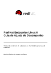
5.1
Our experimental testbed connected with two different interconnects: PCIe
over cable and Infiniband. . . . . . . . . . . . . . . . . . . . . . . . . . . . . . 30
5.2
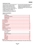
Our testbed.
. . . . . . . . . . . . . . . . . . . . . . . . . . . . . . . . . . . . 31
5.3
Throughput of SDP over PCIe. The numbers 1, 2, 3, 4 refers to the number
of concurrent connections. . . . . . . . . . . . . . . . . . . . . . . . . . . . . . 33
5.4
CPU utilization of SDP over PCIe for the sender and the receiver using 1, 2,
3 and 4 concurrent connections. . . . . . . . . . . . . . . . . . . . . . . . . . . 35
5.5
Throughput-to-peak-pandwidth ratio of SDP over PCIe and Infiniband. . . . 38
xi
5.6
Latency in micro-seconds of SDP over PCIe and SDP over Infiniband. . . . . 39
5.7
File transfer time using SDP over PCIe and SDP over Infiniband. . . . . . . . 39
5.8
Ratio of file transfer speed to peak DMA bandwidth. . . . . . . . . . . . . . . 40
5.9
CPU Utilization of SDP for PCIe and Infiniband. . . . . . . . . . . . . . . . . 42
xii
Chapter 1
Introduction
PCI Express (PCIe) has evolved in recent years to offer high throughput, low latency, low
power consumption, and cost-effectiveness [30]. As PCIe evolution continued to include
host-to-host, over-cable capability, it made it possible to serve as a high performance interconnect for datacenters and High-Performance Computing (HPC) systems. According to
today’s specifications, a bandwidth of tens of GB/s is achievable using multiple-lane PCIe
expansion cards. Moreover, nanosecond-level latency has been achieved [30]. Power rating
is also an important requirement for the scalability of datacenter clusters. Researchers have
shown that PCIe-based network achieves much lower power consumption when compared
to other technologies commonly employed in datacenters. For example, per-node power
consumption for PCIe network is below 1 watt, while it is 10 watts for 10 GigE and 15.5
watts for QDR Infiniband [9]. Furthermore, researchers have demonstrated the ability of
PCIe to provide a power-aware interconnect [20]. PCIe can also be a cost-effective solution for applications running on small-scale clusters. Researchers have demonstrated the
cost/bandwidth advantage of PCIe over Ethernet [28]. The cost savings are due to its
ability to eliminate multiple layers of expensive switches and bridges that previously were
needed to blend various standards [30].
Nevertheless, the adoption of PCIe-based interconnects is limited because of several challenges [9]. The most important challenges, in our view, are ones dealing with applications
portability, throughput/latency, and scalability. In this thesis, we focus on the first two
challenges and briefly describe the challenges related to scalability and describe the available solutions. Notably, the portability of datacenter applications to PCIe-based network
1
CHAPTER 1. INTRODUCTION
2
is not straightforward. For an application to utilize PCIe interconnect, all the usual communication and send and receive system calls need to be replaced with hardware-specific
direct memory access operations. Applications with inherent socket-based design provide
a strong example. Equally important, the design and implementation of the required interface could lead to inefficient utilization of the low latency and high throughput offered
by the underlying interconnect. Especially when the hardware only provides a limited data
transfer options, such as the case for PCIe. Finally, because PCIe was originally designed
as an internal I/O interconnect, it is hard to scale PCIe-based networks up beyond tens of
nodes.
Many datacenter applications as well as some HPC applications rely heavily on socket
calls. Consider, for example, a cluster with web servers, SQL servers, and file storage servers.
Straightforward design and implementation of a socket interface on top of the PCIe layers
can lead to large losses in the overall performance due to multiple data copying throughout the software stack. TCP, as an example, incurs a lot of overhead in its operation that
would not be required on a reliable PCIe link. We have to find a way to implement the
necessary interface while eliminating unnecessary inefficient components. The Socket Direct
Protocol (SDP) has been implemented as an efficient transport protocol to run over Infiniband interconnect [5]. SDP for Infiniband is available for Linux and Windows as part of
the open-source Open Fabrics software stack for Infiniband [2]. SDP for Infiniband has received researchers’ attention. Several papers discuss different implementation aspects, such
as data transfer modes [5, 16, 17, 3], flow-control [4] and quality of service [18]. Similar
protocols with different names have also been implemented for PCIe, such as SuperSocket
by Dolphin [25] and Direct Data Transfer by One Stop Systems [43]. However, these implementations are proprietary and expensive. For example, Direct Data Transfer is sold as part
of ExpressNet2 software stack for $5000 per network [43], which adds significant increase to
deployment cost. Further, explicit benchmarking and application-based comparisons with
leading, competitive technologies are either brief or non-existent.
In this thesis, we present our design and implementation of SDP over PCIe. Our design includes a unique data transfer mode and flow-control mechanism. We evaluate the
performance of our implementation of SDP over PCIe and compare it to that of SDP over
Infiniband. SDP over Infiniband has been chosen as a basis for evaluation as it is a leading
technology for HPC and datacenter interconnects. Based on the evaluation, we define the
characteristics of the niche application areas for SDP over PCIe. Experimental evaluation
CHAPTER 1. INTRODUCTION
3
shows that, when large messages are sent concurrently, the throughput of SDP over PCIe
can achieve up to 98% of the full wire speed. Moreover, evaluating the normalized speed of
web file transfer, as a datacenter application, shows that using SDP over PCIe yields up to
11% improvement when compared to Infiniband. In addition, CPU utilization of SDP over
PCIe is much lower than that of SDP over Infiniband.
1.1
Problem Statement
PCIe has many advantages that makes it attractive as a high performance interconnect. It
also lacks some of the features that most of the other interconnects have, such as advanced
data transfer engines and RDMA operations support. In this thesis, we design a data
transfer protocol that achieves a performance comparable to the state of the art using only
direct memory access to transfer the data.
We propose to design and implement the Socket Direct Protocol over PCIe such that it:
(i) provides transparent support for TCP/Socket based applications, (ii) maintains the low
latency of the link, (iii) utilizes the full bandwidth of the link, and (iv) maintains low CPU
utilization.
The significance of our proposed solution is enabling PCIe be a cost-effective interconnect for high performance computing and datacenter applications. Essential datacenter
applications such as web services and databases can communicate with other servers directly using PCIe cable or over PCIe expansion switch with no change to the applications.
However, for PCIe to be on par with other interconnects in the market, it needs a complete
software stack that includes other protocols like IP over PCIe and middlewares such as MPI
implementation. Our implementation and kernel API can serve as a reference and a basis
to speedup the development of other communication protocols for the PCIe fabric.
1.2
Thesis Contributions
The contributions of this thesis can be summarized as follows:
• We propose to develop the Socket Direct Protocol for PCIe-based fabrics. SDP makes
it possible to run TCP based socket applications without modification. It also maintains the performance of the link by avoiding the overhead of TCP.
CHAPTER 1. INTRODUCTION
4
• We design and implement the Socket Direct Protocol as a Linux kernel module for
PLX variant of PCIe non-transparent bridges leveraging the built-in DMA engine.
Our implementation includes a data transfer and flow-control mechanisms that utilize
the limited transfer methods available in the hardware.
• We conduct an empirical evaluation study based on our implementation and deployment on two computers. We use benchmarks in our evaluation in addition to a real-life
application. We compare the performance of our implementation to that of Infiniband.
• Benchmarking results show that our implementation achieves low latency of 18.34 µs
when transferring small workload and high throughput of 1,220 MB/s when transferring big workloads, which is 98% of the achievable throughput of the link.
• The comparison with the SDP over Infiniband shows that our implementation throughput is very close to Infiniband’s, the latency is not as good as Infiniband’s, and the
CPU utilization for our implementation is better for most cases.
• The application testing results show that our implementation transfers 1 gigabyte file
in 3.4 seconds. By comparing the application results with that of SDP over Infiniband,
we achieve up to 11% improvement in the normalized file transfer bandwidth.
1.3
Thesis Organization
The rest of the thesis is organized as follows: Chapter 2 provides a background about Interconnects in HPC Systems, PCI Express, PCIe Bridges and Interconnects and Socket Direct
Protocol. Chapter 3 Surveys the past efforts relevant to this thesis. Chapter 4 presents
the design and implementation details of our proposed system. Chapter 5 describes the
testbed and experimental setup, followed by results and commentary. Finally, we conclude
the thesis and describe our future work in Chapter 6.
Chapter 2
Background
This chapter provides the background information needed to understand the concepts discussed in this thesis. We present an overview of interconnect used in high performance
computing, background information about PCI Express and Socket Direct Protocol.
2.1
Interconnects in High Performance Computing Systems
A high performance computing (HPC) system consists of multiple computers (compute
nodes) connected with a network (interconnect) as shown in Figure 2.1. HPC systems are
used to execute parallel applications by distributing the work between the compute nodes.
Interconnects play critical role in high performance computing since they provide interprocess communication among the different nodes. Gigabit Ethernet is currently one of the
popular interconnect choices. However, because of its limited throughput and high latency,
it is not suitable for many HPC cluster applications. Communication overhead can have
significant impact on application performance [19]. So, depending on the characteristics of
the applications running on the system, the choice for the interconnect is made [6]. Therefore, there are many specialized interconnects, such as Infiniband, Myrinet, Quadrics, and
Dolphin SCI, that provide the needed high throughput and low latency. At the time of writing, Infiniband is the most employed interconnect for communication intensive applications,
especially in commodity clusters as shown in Figure 2.2. Different network technologies and
topologies are available in the market, some are proprietary and some are open. Examples
for such topologies are point-to-point connections, buses, switched, fat-tree networks, and
mesh networks [19].
5
6
CHAPTER 2. BACKGROUND
User’s&Network&
Master&
Node&
Local&Cluster&Network&
Compute&
Node&
Compute&
Node&
Compute&
Node&
Compute&
Node&
Figure 2.1: General structure of high performance computing systems.
Infiniband&
10.6 %
Gigabit&Ethernet&
Infiniband 44.8 %
Gigabit Ethernet
37.8 %
Custom&Interconnect&
Proprietary&Network&
Cray&Interconnect&
Myrinet&
Fat&Tree&
Figure 2.2: Interconnect family system share in Top500.org November 2012 list [40].
CHAPTER 2. BACKGROUND
2.2
7
PCI Express
PCIe was developed to replace the original 33-MHz, 32-bit PCI parallel bus. The original
bus had a peak theoretical bandwidth of 132 MB/s. It used a shared bus topology to
enable communication among the different devices on the bus [38]. In 2003, the PCI Special
Interest Group (PCI-SIG) introduced PCIe Gen1. PCIe replaced the shared bus with a
shared switch, which provides each device its own direct access to the bus. Data is sent
serially in packets through pairs of transmit and receive signals called lanes. Each lane
provides a transmission data rate up to 2 Gbps. In 2007, the Gen 2 PCIe was released which
doubled the transmission rate of a lane to 4 Gbps. In November 2010, Gen3 specification
was published which increased the transmission rate per lane to 8 Gbps [30]. By aggregating
16 lanes, a transfer rate of 120 Gbps can be effectively achieved with a cut-through latency
of 120 ns [30].
PCIe is a layered protocol, which is divided into three main layers: transaction, data
link, and physical as shown in Figure 2.3. The transaction layer manages the transactions
for communication. The data link layer is responsible for link management, including packet
sequencing and data integrity, which includes error detection and correction [20]. It also includes a mechanism that guarantees delivery using acknowledgment protocol (ACK/NAK).
This reduces the need for higher-level protocol per packet acknowledgment mechanism. The
physical layer includes all circuitry, including a driver with impedance matching and input
buffering, parallel-to-serial and serial-to-parallel conversion [20]. PCIe Gen 1 and 2 links are
8b/10b encoded. This has the net effect of reducing usable PCIe lane bandwidth to 2 Gbps
[29]. However, in Gen 3 the 8b/10b encoding has been replaced with scrambling scheme
which increased the throughput [1].
PCIe uses credit-based flow control, where a transmitter is required to have credit for
a transaction layer packet before forwarding the packet. The mechanism guarantees that a
receiver has space to hold the packet before it is sent and allows the transmitter to adjust
its data flow to match the congestion characteristics of its link partner [29].
PCIe topology consists of multiple components including a root complex, bridges, switches,
and endpoint devices as shown in Figure 2.4. The Root Complex denotes the device that
connects the CPU and memory subsystem to the PCI Express fabric. Bridges permit multiple independent PCIe buses to be connected and to forward operations from one bus to
another when required. A Switch can be thought of as consisting of two or more logical
8
CHAPTER 2. BACKGROUND
Transaction Layer !
Transaction Layer !
Link Layer !
Link Layer !
Physical Layer !
Physical Layer !
Figure 2.3: The logical layers of PCI Express.
PCIe-to-PCIe bridges, each bridge associated with a switch port. One port of a switch has
to point in the direction of the root complex as an upstream port. All other ports point
away from the root complex as downstream ports. Endpoints are devices other than the
root complex and switches. They are peripheral devices such as Ethernet, USB or graphics
devices [8].
PCIe devices are equipped with standard Control and Status Registers (CSRs). These
registers are used by the host to discover the system topology when it is first powered up
or reset. Then the host maps discovered devices into the memory space. Endpoint PCIe
devices use a Type 0 CSR header which includes base address registers (BARs) used to
request memory or I/O apertures from the host. The standard bridge CSR header, called
a Type 1 header, includes primary, secondary and subordinate bus number registers that,
when written by the host, define the CSR addresses of devices on the other side of the
bridge. Bridges that employ a Type 1 CSR header are called transparent bridges [8].
2.3
PCIe Non-Transparent Bridges (NTB)
NTB is used to connect two computers using PCIe. Like PCIe transparent bridges, PCIe
non-transparent bridges are used to expand the number of possible PCIe slots in the system.
However, a PCIe non-transparent bridge has the ability to connect two independent PCIe
domains or root complexes. This kind of bridge makes it possible to connect endpoints
that have their own processor. Without a non-transparent bridge, upon power up or reset,
intelligent endpoints attempt to enumerate the entire system, causing system conflict and
9
CHAPTER 2. BACKGROUND
CPU !
Endpoint
Memory
Root
Complex
PCIe
PCIe
Switch
PCIe
PCIe
PCIe
PCIe
Endpoint
Endpoint
Endpoint
Endpoint
Figure 2.4: PCIe topology components.
ultimately a non-functional system. Intel was the first to use non-transparent bridges in
PCI systems in its DrawBridge products which established the idea and became a de facto
standard [39].
A non-transparent bridge exposes a Type 0 CSR header on both sides and forwards
transactions from one side to the other with address translation, through a memory window
created by the BARs of those CSR headers. Because it exposes a Type 0 CSR header,
the bridge appears to be an endpoint to discovery and configuration software, eliminating
potential discovery software conflicts [8].
Two processors may exchange status information through scratchpad and doorbell registers. The number of registers varies between implementations. Scratchpad registers are
fully accessible from both sides of the bridge and are used for generic inter-processor communications. Doorbell registers are used to send interrupts from one side of the bridge to
the other. They are usually utilized to indicate both the health of the hardware and various
client driver states [37]. To transfer data between two systems, the device drivers on both
ends allocate some region of physical memory and use the scratchpad and doorbell registers
to inform each other of the amount and the location of the physical memory allocated.
Then, the pair of device drivers work together to initialize the non-transparent bridge to
10
CHAPTER 2. BACKGROUND
System A
System B
0xffffffff
0xffffffff
NTB Address
Space
NTB Address
Space
NonTransparent
Bridge
Driver
Physical
Memory
0x00000000
Driver
Physical
Memory
0x00000000
Figure 2.5: Non-transparent bridge (NTB) remote memory address translation.
enable address translation [31]. Once the address translation is in place, each side can read
and write to the mapped remote host memory as shown in Figure 2.5.
With the help of non-transparent bridge, Multiple nodes can be connected to form a
network using different topologies. Using a PCIe cluster switch, a small cluster can be built
as shown in Figure 2.6. Multiple switches can also be connected in various configurations
to support larger cluster size [25].
2.4
Socket Direct Protocol
Traditional implementation of TCP/IP is not suitable for high performance interconnects
such as Infiniband and PCI express. It depends on the kernel for processing the messages,
which causes multiple copies and kernel context switches in the critical message passing path
which increase the latency. TCP is also no longer needed to transfer data between two endpoints when the physical interconnect is reliable and provides transport-level functionality.
However, many applications have been developed based on socket interface, which makes
socket-support essential.
The Socket Direct Protocol (SDP) was originally an Infiniband Architecture-specific
CHAPTER 2. BACKGROUND
11
Figure 2.6: General PCIe network topology.
protocol defined by the Infiniband Trade Association [5]. SDP now has been redefined as a
transport agnostic protocol for Remote Direct Memory Access (RDMA) network fabrics by
the RDMA Consortium [11]. According to SDP specifications [33], SDP has been designed
with two goals in mind. First, existing socket-based applications should be able to use the
SDP protocol without any code modification or recompilation. Second, SDP has to support
byte-streaming over a message passing protocol, including kernel bypass data transfers and
zero-copy data transfers.
The current SDP over Infiniband implementation supports two data transfer modes,
buffer copying (bcopy) and zero-copying (zcopy) [16]. These two modes are able to utilize
the advanced technologies included in the Infiniband adapters, such as the sophisticated
DMA engine, the transport engine, and the management capabilities. Bcopy mode copies
the data from the application buffer to the NIC private buffer. Then it utilizes Infiniband
hardware-offloaded protocol stack to transfer the data to the other host [4]. Bcopy is able
to pipeline transactions on the wire [16]. On the sender side, send() returns as soon as
the data is copied to the private buffer. Therefore, multiple send() operations can be
submitted while some of the previous send() operations are being served. This increases
the link utilization and maximizes the bandwidth. However, bcopy incurs a local data
copy overhead. This overhead increases with the speed which substantially increases CPU
utilization and becomes a performance bottleneck. Bcopy flow is shown in Figure 2.7.
Zcopy transfers the data from the application buffer of the sender to the application
buffer of the receiver through RDMA operations using the DMA engine. This process
12
CHAPTER 2. BACKGROUND
ApplicaFon&A&
Buffer&
SDP&
Wire&
SDP&
ApplicaFon&B&
Send()&
Copy&&
to&SDP&
Buffer&
Return&
Block&
waiFng&
for&data&
Recv()&
Buffer&
Return&
when&
copy&is&
done&
Copy&&
to&app&
Buffer&
Return&
Figure 2.7: Bcopy data flow [16].
ApplicaFon&A&
SDP&
Wire&
SDP&
ApplicaFon&B&
Send()&
Buffer&
Register&and&
AdverFse&
SrcAv
ail&
Buffer&
Wait&for&
app&to&post&
Recv()&
A&Rd&
Return&
Deregister&&
RDM
Register&and&
RDMA&Rd&
Rd&
Rdma &
l
Comp
Indicate&
CompleFon&&
Deregister&&
Figure 2.8: Zcopy data flow [16].
Return&
CHAPTER 2. BACKGROUND
13
requires the buffers to be pinned-down by marking the relevant memory pages as nonpageable and registered with the Infiniband adapter. This mode results in high throughput
when large blocks are transferred and minimizes the CPU utilization since no data copying
is required. Nevertheless, zcopy incurs the overhead of locking the application buffers and
registering them with the Infiniband adapter, as well as buffer advertisement overhead.
Thus, zcopy is not suitable for transferring small data sizes. Therefore, a combination of
these modes is used and the selection of the mode is determined by a threshold. Zcopy flow
is shown in Figure 2.8.
Unlike Infiniband adapters, PCIe adapters are much simpler and lack most of the advanced features available in Infiniband. This simplicity is reflected on our SDP over PCIe
design as we will show in more details later.
Chapter 3
Related Work
Several related efforts confirm that high performance can be obtained by employing PCIe
[26, 24, 20, 37]. Most research considers latency and throughput as the major performance
metrics [21]. Some research touchs upon the scalability aspects of the PCIe interconnect
[20], while other works describe software stacks for applications to interface with PCIe as
the lower layer of the OSI model [25].
Hanawa et al. [20] proposed using PCIe as a communication link that provides powerawareness, high reliability, and high performance. The link is based on PCIe Gen 2 with
4 lanes. Using the link, they obtained high performance and reduced power consumption
compared to Ethernet and Infiniband. They achieved this by limiting the length of the link to
distances of several meters and by shrinking the number of lanes or by reducing the transfer
rate by half. Results show a latency of 10 µs and peak transfer rate of 520 MB/s, 65% of the
theoretical peak performance. The authors did not use non-transparent bridges in their PCIe
fabric. They believe that non-transparent bridge provides undependable network. Their
justification is that the fabric requires one node to be the root complex. When this node fails,
switch reconfiguration is required and the all nodes need to be rebooted. So, instead they
utilized their own communicator chip that requires no switches reconfiguration. However,
non-transparent bridge chip makers [39] and [22] show that a high availability solution is
available by using a dual root complex topology where the second root complex can take over
when needed without systems reboot. The authors also have not implemented a software
stack for the fabric and planned it for future. In this thesis, we used non-transparent bridge
based PCIe fabric and implemented the socket direct protocol as a software stack for the
fabric.
14
CHAPTER 3. RELATED WORK
15
Kapoor et al. [21] explored the details of specific use cases that can be addressed with
PXI MultiComputing (PXImc). PXImc is a specification developed by the PXI System
Alliance (PXISA) to standardize the use of PCIe over cable and non-transparent bridges
to connect multiple test and control systems [31]. They benchmarked PXImc compliant
prototype hardware and preliminary software stack and reported achieving a latency of
6 µs and throughput of 670 MB/s when two PXImc-compliant devices were connected.
They concluded by recommending the use of PXImc based interconnect for building high
performance multi-computer test and control systems. The authors focused on utilizing
PCIe fabric for test and control systems, while our work is focused on utilizing PCIe fabric
for datacenter and HPC applications. The authors also did not include any details about
the software stack they used which we did in this thesis.
Krishnan [24] suggested integrating the I/O and cluster networks in an HPC environment
into a single PCIe-based fabric network. As PCIe continues to evolve, the author saw no
need for other non-PCIe fabric such as Infiniband. The author also presented an interconnect
solution by Dolphin that allows such integration based on PCIe fabric. Then he described
the implementation of IP over PCIe (IPoPCIe) and compared the performance with 10G
Ethernet. The results show that IP over PCIe was able to achieve performance on par or
better than that of a 10GigE NICs performance. In a later paper [25], Krishnan revealed
more details about the Dolphin interconnect implementation of PCIe hardware and software.
Instead of using IP over PCIe (IPoPCIe), the authors introduced a socket direct approach
for PCIe called SuperSockets that bypasses the TCP/IP stack. The evaluation showed that
SuperSockets-based connection was able to reduce latency to 2 µs of latency. SuperSockets
seems to have similar general idea as SDP we propose in this thesis. However, their software
is proprietary and the author mentioned no design or implementation details. Also the
evaluation part only benchmarked the latency and the throughput and did not evaluate the
CPU utilization and applications performance. While our work is open-source [7] and covers
all the design and implementation details. In addition, we evaluated the CPU utilization
and compared it to the state of the art.
Byrne et al. [9] examined the opportunities and challenges of using PCIe-based fabrics
in terms of performance and power consumption. They ran different workloads of both
Ethernet and PCIe fabrics and compared the result. The experiments identified Ethernet as
a performance and energy efficiency bottleneck, especially for data intensive systems with
power-optimized compute and storage systems. Performance measurements showed that the
CHAPTER 3. RELATED WORK
16
PCIe network enables 60% to 124% better energy efficiency. One of the challenges pointed
out in the paper is to choose the right API and protocol to expose the PCIe local networks.
In this case, they chose to port the applications to support PCIe network by replacing all
HTTP-based calls with PCIe native calls, whereas, in our work, we implemented socket
direct protocol to avoid any application code changes.
Another related area is the effort to implement and enhance SDP for other interconnects
such as Infiniband and iWARP over 10G Ethernet and for other platforms such as the
Windows operating system. Balaji et al. [5] introduced SDP over Infiniband and studied the
benefits and limitations of SDP. They also evaluated the performance using benchmarks and
real applications. The results were compared with that of IP over Infiniband and showed that
SDP provides up to 2.7 times better bandwidth than IP over Infiniband. Cohen [10] studied
the performance of an SDP implementation over 4X Infiniband that supports asynchronous
zero-copy transfers. Goldenberg et al. [17] introduced a version of SDP over Infiniband
that supports synchronous socket using zero-copy transfers. Goldenberg et al. then [15]
introduced their implementation of SDP over Infiniband for the Windows operating system
and presented preliminary performance results. Balaji et al. [4] proposed to improve the
flow-control on SDP over Infiniband by utilizing the flow-control capabilities provided by the
Infinibannd hardware. Then, Grant et al. [18] analyzed the performance benefits of quality
of service provisioning in Infiniband networks for SDP and IP over Infiniband. Panda
in his thesis [32] focused on designing and enhancing SDP over iWARP and Infiniband.
As can be noticed, SDP over Infiniband has been studied very well and its design was
influenced by different Infiniband Architecture-specific technologies. Our work is inspired
by the Infiniband implementation. However, we have performed a complete redesign for the
data transfer and flow-control mechanism to fit the PCIe architecture.
In summary, previous works support our direction in utilizing PCIe over cable as a high
performance interconnect. However, only few attempts were reported to build and evaluate
software stack for the fabric and these attempts are based on proprietary software and
briefly described with no application testing results. Infiniband on the other hand, has been
the focus for many researchers who contributed in improving its open-source software stack
including its SDP implementation.
Chapter 4
Proposed System
4.1
Overview
As we have shown in Chapter 2, PCIe over cable can be used to connect two machines
provided that one of them is equipped with a non-transparent bridge to be isolated from
the root-complex. Further, multiple machines can be connected using PCIe expansion switch
or multiple switches given that one machine is connected directly to the switch to be the
root-complex while the rest of the machines are connected using non-transparent bridges.
The resultant network provides high performance for low cost and power consumption.
However, this network is missing the software stack that interfaces the applications with the
fabric.
We propose to design and implement the Socket Direct Protocol as a Linux kernel
module for PCIe-based fabric. Our work involves building a kernel-level API exported by
the non-transparent bridge and DMA device drivers for the kernel module to interface with
the drivers. The SDP kernel module utilizes our API to translate socket calls to DMA
operations and PCI memory mapped I/O reads and writes to the remote system memory.
This solution provides the full performance of the fabric without the need for modifying the
applications.
To migrate an application from TCP to SDP without changing its code, a user-level
socket switch is used. The socket switch is a preloaded library that uses rules defined by
the users in a configuration file to choose between TCP and SDP sockets, then routes each
socket to the right kernel module.
Our design has the following components: SDP socket preloaded library, SDP kernel
17
18
CHAPTER 4. PROPOSED SYSTEM
User+Space+
Applica'ons+
SDP+Socket+Preloaded+Library+
Kernel+Space+
Protocol+Switch+
TCP+
IP+
NIC+Driver+
Ethernet+NIC+
SDP+Kernel+
Module+
Communica'on+
API+
DMA+
Driver+
NTB+
Driver+
PCIe+NTB+Adapter+
Figure 4.1: Overview of SDP over PCIe architecture.
module, Kernel-level API and Non-transparent bridges and DMA drivers. Figure 4.1 shows
an overview of SDP over PCIe architecture.
4.1.1
SDP Socket Preloaded Library
SDP kernel module registers SDP as a new address family (AF INET SDP). Normally for
any socket application to use a new address family, the source code needs to be modified to
replace AF INET with the new address family. However, Infiniband software stack developers
found a workaround to allow TCP based socket applications to run seamlessly with no
modification or recompilation to the code by developing a preloaded library that can be
used to switch between address families based on user defined rules. The user can choose
between TCP and SDP by defining a rule in a configuration file based on process name, port
19
CHAPTER 4. PROPOSED SYSTEM
int!main(int!argc,!char!*argv[])
{
!!!int!sockfd;
!!!int!len;
!!!struct!sockaddr_in!address;
!!!int!result;
!!!//Create!socket!for!client.
!!!sockfd!=!socket(AF_INET,!SOCK_STREAM,!0);
!!!address.sin_family!=!AF_INET;
!!!address.sin_addr.s_addr!=!inet_addr("127.0.0.1");
!!!address.sin_port!=!htons(7734);
!!!len!=!sizeof(address);
!!!result!=!connect(sockfd,!(struct!sockaddr!*)&address,!len);
!!!...
int!main(int!argc,!char!*argv[])
{
!!!int!sockfd;
!!!int!len;
!!!struct!sockaddr_in!address;
!!!int!result;
!!!//Create!socket!for!client.
!!!sockfd!=!socket(AF_INET_SDP,!SOCK_STREAM,!0);
!!!address.sin_family!=!AF_INET_SDP;
!!!address.sin_addr.s_addr!=!inet_addr("127.0.0.1");
!!!address.sin_port!=!htons(7734);
!!!len!=!sizeof(address);
!!!result!=!connect(sockfd,!(struct!sockaddr!*)&address,!len);
!!!...
Figure 4.2: Code snippet in C shows the difference between TCP socket (left) and SDP
socket (right).
number, or IP address. We use a similar approach as SDP Infiniband implementation. We
register our implementation to the same address family used by Infiniband implementation
of SDP and use the same preloaded library. An applications developer also has the option
to natively support SDP and skip the use of this component by using AF INET SDP directly
as shown in Figure 4.2.
4.1.2
SDP Kernel Module
The SDP kernel module is the main component of our solution. It implements all functions
which the kernel expects from any transport layer protocol such as connect, disconnect,
accept, sendmsg and recvmsg. The kernel then maps all socket calls to functions defined
by this module. When the module is loaded, it registers the protocol in the kernel and
associates the protocol to an address family. Then, it allocates 1 MB physically contiguous
memory to be used as send buffer. After that, the kernel becomes ready to handle any
socket request to this protocol.
4.1.3
Non-Transparent Bridge, DMA Drivers and API
The drivers used in our implementation are part of PLX Technology Software Development
Kit [35]. The SDK has a non-transparent bridge device driver, a DMA engine device driver,
and a user-level API. However, we could not find a standard way to utilize the drivers
capabilities from the kernel side. So we have written a kernel-level API on top of the drivers
to allow the SDP module to interact with the hardware. The API includes functions to
open the device, close the device and a function to send control messages to the device.
CHAPTER 4. PROPOSED SYSTEM
20
The drivers also do not provide functions needed to support asynchronous I/O. So, we have
modified the drivers to add the needed functionality.
4.2
Detailed Design and Implementation
The general structure of the kernel module is similar to SDP over Infiniband kernel module
and TCP component of Linux kernel. However, due to the many differences in hardware between Infiniband adapters and PCIe adapters, a straightforward port of SDP is not possible.
In particular, Infiniband adapters are equipped with two advanced data transfer methods,
Transport Off-load Hardware and Advanced DMA Engines. Transport Off-load Hardware
enables the adapter to transfer the data from the adapter memory to the memory of the
remote adapter, which offloads the CPU. The DMA engine supports the advanced RDMA
operations that eliminate the need to copy data from the application to the kernel. On the
other hand, PCIe adapters are only equipped with DMA engines that do not support application buffer to remote application buffer data transfers. Therefore, bcopy and zcopy data
transfer modes described in Chapter 2 cannot be implemented for PCIe fabric. Nevertheless,
using the available hardware resources we designed a data transfer mode and a flow-control
mechanism that achieve performance comparable to that of SDP over Infiniband.
4.2.1
DMA Memory Requirements
As discussed earlier, the only means of communication provided by the hardware is remote
memory access either by mapping the remote memory or by DMA operations. The main
issue that arises when using DMA is the strict memory requirements. For the memory to
be DMA friendly, it has to be physically contiguous [14]. Contiguous memory is a scarce
system resource, as the memory gets fragmented by time [14]. In addition, the memory must
neither be cached by the CPU nor be swapped. Caching and swapping cause the local and
remote DMA engines to access the wrong version of the data, which leads to data corruption.
Therefore, the physical memory pages have to be pinned by the operating system to prevent
the virtual memory system from paging them out during the transfer. User space memory
is not contiguous, so it cannot be directly accessed by the DMA engine. However, many
devices, including the PCIe hardware, support transferring scattered memory by passing a
scatterlist of memory pointers and lengths, to be transferred in one DMA operation. One
additional memory requirement is needed when the destination of the DMA transfer is a
CHAPTER 4. PROPOSED SYSTEM
21
remote host, which is address translation. In our case, the non-transparent bridge provides
a remote memory address translation mechanism. All these requirements as well as the
overhead incurred when using DMA such as DMA starting overhead and memory pinning
and translating overhead influenced our design.
In our implementation, we choose to allocate two DMA buffers per socket, one for sending
and the other for receiving. These buffers are pinned and reused through out the connection
session to avoid the pinning and translating overhead. We use these buffers to temporarily
store the data copied from the user space application buffer, before it is transferred to the
other host. We could not perform zero-copy transfers between the two user space application
buffers because even with the scatterlist support, our hardware requires that the remote
buffer to be contiguous. One suggested solution to this problem is to use of huge pages
feature supported by linux [13]. Huge pages feature divides part of the system memory
into much larger contiguous memory pages than what was available before. This makes the
user space application buffer contiguous, as the whole buffer fits in a single page. However,
the use of memory allocated using huge pages is not transparent to the applications and
requires code changes. So, it is not suitable in our case, since we aim to provide a transparent
solution.
In the case of multiple concurrent connections, each connection needs to have its own
send and receive buffer. So, the allocated send buffer most be shared by all connections.
Currently, the buffer is divided in code into four buffers to support up to four connections.
However, this method leads to inefficient use of the scarce memory when the number of
connections is less than four. So, this issue needs to be addressed in future work by developing a memory management mechanism that divides the memory dynamically among the
connections.
4.2.2
Data Transfer Mechanism and Flow Control
Our data transfer mechanism is based on the use of bounce buffers. Similar to bcopy,
the sender copies the data to the bounce buffer every time send() is called and returns
immediately. This allows the sender to combine multiple send requests into one data transfer
operation. However, unlike bcopy, data transfer is performed using the DMA engine or PCI
memory mapped I/O depending on the data size. For latency critical small data transfers,
PCI memory mapped I/O is used, while DMA is used for data of large sizes. A diagram that
shows the data flow in the proposed transfer mechanism is shown in Figure 4.3. Another
CHAPTER 4. PROPOSED SYSTEM
22
difference from bcopy is that the transfer in our mechanism does not start immediately, but
starts after one of the following four conditions is satisfied.
1. When the buffer is full and no more data can be copied.
2. When send() is followed by receive(). This condition is important to avoid deadlocks that could happen when both sides call send() then call receive() at the same
time.
3. When the sender calls close().
4. If the data copied is smaller than a certain threshold. This condition is to avoid
unnecessary delay for small data to improve the latency.
This means our mechanism does not have the advantage of pipelining the data like what
bcopy does. This is because pipelining requires sending the data immediately, which is
expensive in our case due to the high overhead associated with starting the DMA engine.
To control the data flow, the DMA engine of the receiver side performs the actual
transfer. Thus, the sender must wait for the transfer to finish before it continues copying
more data to the buffer. This ensures that the sender does not send more than what the
receiver can receive.
The proposed transfer mechanism has some pros and cons. One advantage of our mechanism over zcopy is the elimination of memory pinning overhead, memory registration overhead, and buffer advertising overhead that zcopy incurs since we use the same buffer through
out the life of the connection. Another advantage is amortizing the overhead of starting
the DMA engine over multiple send() requests by combining the data. This allows us to
effectively use the same transfer mode for all data sizes unlike SDP over Infiniband which
needs to switch between transfer modes.
The main disadvantage of our mechanism is the under utilization of the link. This
happens when the data that needs to be sent is larger than the bounce buffer. In this
case, the sender needs to fill the buffer multiple times and waits for the receiver to copy
data from the sender buffer. This disadvantage is especially clear for a single connection
and disappears when multiple concurrent connections take place. Another disadvantage is
memory copying on both sides, which increases the CPU utilization. Both of the above
disadvantages also contribute to increases in latency.
23
CHAPTER 4. PROPOSED SYSTEM
ApplicaFon&A&
Buffer&
SDP&
Wire&
SDP&
ApplicaFon&B&
Send()&
Copy&to&SDP&
Buffer&
Return&
Block&waiFng&
for&data&
Recv()&
Buffer&
Return&when& Data&ready&
copy&is&done&
DMA&compl&
Copy&to&app&
Buffer&
Return&
Figure 4.3: Data flow of the proposed data transfer mechanism.
4.2.3
SDP Connection
Similar to TCP, SDP is connection-oriented; it requires a handshake between the two processes before one application process can send data to the other. The handshake is needed
to exchange IP addresses, port numbers and memory addresses. As explained earlier, each
machine connected to PCIe fabric sees other machines as endpoint devices. So, for the server
to listen to a socket, it needs to open every NTB device in the network and writes a message
indicating that it is ready to connect. Since the listening machine does not know the remote
machines memory addresses, the only way to communicate is via the shared scratchpad
registers (mailboxes) accessible from both sides. The client side knows exactly which device
in the fabric it needs to open as it resolves the IP address of the server to its device number.
Using this method, both sides exchange send buffer memory address. Then, they translate
the remote memory address to a local memory address using translation register provided
by the non-transparent bridge. Once the memory addresses are translated, they can be
used for communication instead of the shared mailboxes. Following is a step-by-step walk
through the connection establishment process:
1. As shown in Figure 4.4, the server side calls listen() to change the state of the
24
CHAPTER 4. PROPOSED SYSTEM
Client
Server
- Listen()
Scratchpad registers
- accept()
Server port
Ready
Conniction ID
- Connect()
- Read Reg.
Time
client buf addr
Client Buffer
Create client Buffer
Interrupt
- Read registers
Create server Buffer
Server Buffer
Interrupt
Connection established
Interrupt
Connection established
Figure 4.4: The connecting process.
socket to TCP LISTEN. Then, listen function opens the non-transparent bridge device
or devices as a preparation to accept incoming connection.
2. Server calls accept(), this results in writing the port to which the server is listening
and a message indicating that it is ready to connect to one of the mailboxes. It also
generates a random number and writes it to another mailbox. The random number
serves as an identifier for the current connecting trial.
3. Server calls schedule timeout() which sends the process to sleep and releases the
processor until an interrupt comes or timeout happens.
4. Client calls connect(), which resolves the IP address to the device number and opens
that device. Then it becomes able to check mailboxes to read the messages from the
server.
5. If server is listening, the client writes its IP address and port number to the send
buffer and posts the address of the buffer and the connection identifier to the server
via mailboxes.
6. Client sends an interrupt to the server to wake it up to handle its connection request
CHAPTER 4. PROPOSED SYSTEM
25
and calls schedule timeout() to release the processor and wait for server’s signal.
7. Server reads the mailboxes, translates and maps the client’s send buffer, then reads
and saves the client IP and port from the buffer.
8. Server writes the address of its buffer to the client’s buffer, then signals the client and
goes to sleep to wait for final acknowledgment from the client.
9. Client checks its buffer for the memory address for the server send buffer, translates
and maps the address and finally sends a signal to wake up the server and establish
the connection.
For a host to disconnect, it writes FIN CLOSE, and the connection identifier to a mailbox,
and then sends an interrupt to the other side. In case the other side is waiting for some
data, it wakes up because of the interrupt, otherwise it will eventually check the mailbox
and see the disconnect message. Once that happens, the hosts change the connection state
to TCP CLOSE and closes the connection.
4.2.4
Send-and-Receive Process
Send and receive are the most important functions in any transport layer protocol. The
way they are designed has direct impact on the throughput of the connection. To maximize
the throughput, it is important to minimize the amount of work performed in these two
functions. Each instruction executed inside these functions adds up to the total transfer
time and contributes to slowing down the transfer speed. In our design, we consider any
instruction other than the actual transfer as an overhead and aim to minimize it.
As described earlier, the sender prepares the data by copying it from the application
buffer to the kernel send buffer. After the data is transferred, the receiver copies the data to
its kernel buffer, then to the application buffer. The sender buffer is divided into three fields:
sequence number field, data size field and data field. Sequence number field is used by the
sender to store the sequence number of the send attempt. The receiver verifies that the data
is new by checking that its sequence number matches the expected sequence number. Then
the receiver reads the data size field to prepare for data copying. The sequence number
field also is used by the sender to inform the receiver when it runs out of data by writing a
special sequence number.
26
CHAPTER 4. PROPOSED SYSTEM
-*.)
!"#"$%&'()
!45!"#"6%71
2"#$+
/*23 8
2"#$8
/*23 9
2"#$9
777
!"#"/)"01$*2+"3
4(5,5-)
/*23 +
!"#$"%&''()*' +,"-
777
'*-6
&') -
.##>52(,5"-
:0;<=%
:0;<=%
'*-6
&') +
'*-6
&') 8
'*-6
&') 9
!"#$"%&''()*' +,".%,*/01.
.##>52(,5"-
!"#"$*+,
/*23 2"#$-
Figure 4.5: The interactions between the application and SDP during sending and receiving
data.
Since our implementation resides in the kernel, we have to be careful about the way
we use CPU time. Any unnecessary waiting freezes the whole kernel. Therefore, in many
occasions we chose to release the CPU and goes to sleep waiting for an event. This introduces
CPU context switching overhead, which increases latency and reduces throughput. However,
it is important for system stability and responsiveness. For example, when the sender
prepares the data for the receiver, it releases the CPU and goes to sleep waiting for the
receiver to finish copying the data. Another example is when the receiver requests a DMA
operation to copy the data, the receiver goes to sleep waiting for the DMA transfer to finish.
Figure 4.5 and the following walk through show how all above details come together.
Following is a step-by-step walk through the send and receive process:
1. Sender checks if its send buffer is busy by checking the sequence number field, if it
contains a valid sequence number then the buffer is busy and the sender must wait for
receiver signal, else the buffer is free.
2. Sender copies the data from the application buffer to the send buffer and updates the
total size of the data on the size field.
3. If the buffer is full, sends the data by incrementing the sequence number and sending
a signal to the receiver side.
CHAPTER 4. PROPOSED SYSTEM
27
4. Else, exits the send function, and the data is sent when the buffer gets filled by the
next send call, or when receive is called or when close is called.
5. Receiver checks if there is data in its send buffer not sent yet and sends it.
6. Receiver checks if there is data from the last receive call that has not been copied to
the application buffer yet, then copies it and exits.
7. Receiver checks remote host’s send buffer sequence number field, if sequence number
is valid and if the data is large, then, starts a DMA transfer from the remote buffer
to the local receive buffer, else if it is small, then, copy it using read32 operation.
8. If the sequence number is not valid, waits for the sender signal and when the signal
received it does step 7.
9. After copying the data, receiver invalidates the sequence number by writing a message
to the remote host send buffer to indicate that the data in the buffer is no longer
needed, then sends a signal to the sender.
10. Receiver tries to copy the data from the receive buffer to the application buffer if it
fits, else copies part of the data and keeps the rest for the next receive calls.
4.2.5
Simultaneous Connections
Our current implementation supports up to four simultaneous connections per host, which is
the number of available DMA channels. When more than one connection is needed, the send
buffer is divided into smaller buffers dedicated for each connection. Then, each connection
exchanges data with the other side independently. To support more than four connections,
a scheduling mechanism needs to be implemented, which will be addressed in our future
work.
4.2.6
Asynchronous Sockets
Our SDP implementation supports applications using event-driven programming or selectbased multiplexing. Instead of calling accept and waiting for a new connection when select
is called, an event notification is registered with the non-transparent bridge driver. When a
connection request signal is sent from the other side of the connection, the driver captures
CHAPTER 4. PROPOSED SYSTEM
28
the signal and calls a callback function that leads to calling accept. Similarly, receive is
not called until a data-ready signal is received from the other side. This type of socket is
commonly used in web servers and other network applications.
4.3
Scalability to Multiple Nodes
As discussed in 2.3, a network of multiple nodes can be built using PCIe expansion switch
with the help of non-transparent bridge. One node has to be connected directly to the switch
to act as the root complex. All the other nodes have to be connected via non-transparent
bridges. Because of the hierarchical nature of the PCIe enumeration, the root complex is
the only node in the network that can see all the other nodes. It detects all the nodes as
endpoints and uses one of their base address registers (BARs) to request memory apertures
for data exchanges. The endpoints, on the other hand, can only see the root complex since
the enumeration process stops at the non-transparent bridge and cannot discover what is
behind the bridge. This behavior is acceptable for a network of two nodes, however, for
more than two nodes network, a fabric discovery mechanism need to be implemented.
Different vendors proposed and implemented different solutions [34, 39, 23] depending
on the hardware used. The number of nodes supported ranges from six to one thousand
nodes [36]. Some of these solutions also support dual root complex for high availability and
nodes hot plugging. All the solutions share the same generic idea. The root complex detects
all the nodes, and then it broadcasts the information about each node to the other nodes
in the network. After that, the nodes become able to map the memory of each other node
and exchange data and send interrupts directly without involving the root complex.
Since direct memory access and sending interrupts become available after using the
discovery mechanism, our SDP implementation can support multi nodes after some minor implementation changes. Most of the changes are related to the connection process.
Particularly, the IP address resolution has to be changed to adapt with the new discovery
mechanism. When the root complex first discovers a node, it needs to ask it about its IP
address and stores it in an IP-to-memory-location table. Then, this table is shared with all
the nodes to be used for address resolution.
Chapter 5
Experimental Evaluation
5.1
Experimental Setup
All experiments are performed on a system of two nodes connected through a PCIe link.
To compare the performance of SDP over PCIe to that of SDP over Infiniband, the testbed
is also equipped with Infiniband adapters. (See Figure 5.1).
The first node is equipped with Intel Core2 Duo E8400, 3 GHz CPU, and the other
node with quad core Intel Xeon E5420 2.50GHz CPU. Both nodes have 4 GB of RAM.
Each node is equipped with One Stop System PCIe x4 Gen2 switch-based cable adapter
OSS-PCIe-HIB35-x4 with PLX PEX 8609 chip and connected by a 2-meter copper cable
[42]. The hardware shipped with disabled non-transparent bridge functionality, so we had
to reprogram the EEROM of the adapter to enable it. The software stack on the machines is
based on linux-2.6.274 and RedHat 5.7 Linux distribution. The driver for the PCIe adapters
is PLX 6.5 with some modifications. For Infiniband, we use Mellanox single-port, 4X QDR
MT26428. Figure 5.2 shows a picture of the testbed and the adapters.
We evaluate the proposed system based on several performance metrics. The metrics we
used fall under two main categories: benchmarking metrics and application-level metrics.
Benchmarking metrics include throughput and latency for end-to-end performance evaluation, and CPU utilization for computational load assessment. The application-level metrics
include file transfer time and file transfer speed for a file transfer application as a real-life
datacenter application.
In addition, to compare our approach to the state of the art, we use additional normalized metrics. The rationale behind normalized metrics is to be able to compare different
29
30
CHAPTER 5. EXPERIMENTAL EVALUATION
Computer+I+
+
Infiniband+Adapter+
PCIe+Adapter+
Computer+II+
+
PCIe+Adapter+
Infiniband+Adapter+
Figure 5.1: Our experimental testbed connected with two different interconnects: PCIe over
cable and Infiniband.
technologies with different underlying bandwidths. It is difficult to obtain adapters for
two different technologies that deliver the exact peak bandwidth. Therefore, we normalize
metrics to the peak bandwidth in each case. We measure throughput-to-peak-bandwidth
ratio as benchmark comparison metric, and file-transfer-speed-to-peak-bandwidth ratio as
an application-level comparison metric. We define the peak bandwidth as the maximum
achievable bandwidth using raw DMA transfers in PCIe case and using RDMA transfers in
the case of Infiniband.
We have conducted several sets of experiments to measure the metrics described above.
The first set of experiments to measured average throughput, which is the total data transferred over a period of time. We used Iperf 2.0.5 network testing utility [44] which creates
a connection between two nodes and sends messages of fixed size repeatedly. The throughput is calculated as the aggregate number of bytes transferred per second. We repeated the
same experiment for one to four concurrent connections. We also measured the peak CPU
utilization for the sender and the receiver during these experiments using vmstat system
monitoring tool.
In the second set of experiments, we measured the latency, which is the round trip time
for a message of a certain size divided by two. We used NetPipe 3.7.1 utility to measure
the latency, which performs simple ping-pong test, bouncing messages of increasing size
between the two hosts. We repeated the test several times and the total time was averaged
over the number of iterations.
In the third set of experiments, we measured file transfer time and file transfer rate by
downloading files from a web server. File transfer time is the time needed to transfer a
file of a certain size, while file transfer rate is the time needed to transfer the file over the
CHAPTER 5. EXPERIMENTAL EVALUATION
(a) PCIe adapters in the middle of the picture and Infiniband adapters in the edges.
(b) Our testbed with PCIe adapters in.
Figure 5.2: Our testbed.
31
CHAPTER 5. EXPERIMENTAL EVALUATION
32
size of the file. The web server we used is Apache 2.2.3 installed on one node, while used
wget 1.11.4 as a web client on the other node. Files with different sizes were requested by
wget and served by Apache. For every file size, we repeated the experiment and logged the
average file transfer time.
In the fourth set of experiments, we compared the performance of our SDP implementation to that of the state of the art. We chose SDP over Infiniband because it is one of
the dominant interconnects used in many applications including HPC and datacenter applications. The Top500.org list released in November 2012 shows that Infiniband is the most
commonly used interconnect family in supercomputers with a share of 44.8% [40]. We repeated the throughput, latency, and file transfer experiments above for SDP over Infiniband.
To compute the normalized metrics, we measured peak bandwidth for both SDP implementations. To do so, we used the native performance measurement utility provided by the
manufacturers of Infiniband and PCIe adapters to measure the bandwidth for increasing
data sizes and choose the maximum. Therefore, we obtained one peak bandwidth figure
for each of the systems under comparison. Then we used peak bandwidth to normalize the
throughput and the file transfer rate.
5.2
5.2.1
Performance of the Proposed System
Throughput
The throughput results are shown in Figure 5.3. It is clear from the figure that the throughput increases with the transferred data size. The link utilization increases as the link idle
time becomes insignificant compared to the actual data transfer time. Generally speaking,
using multiple concurrent connections increases the throughput for larger message sizes (>4
KB), while for smaller message sizes, it slightly affects the bandwidth by a small margin.
Focusing on the larger message sizes, it is evident that 3 concurrent connections exhibited
performance improvement over 2 connections, which, in turn, was an improvement over a
single connection. However, the 4 connections case did not maintain the pattern since it did
not outperform the 3-connections case.
The results can be explained as follows. First, for small message sizes, the overhead of
concurrency was large compared to the actual data transfer. Thus, a single connection performed better. On the other hand, when message sizes are large, the concurrency overhead
eventually paid off, and multiple connections were able to outperform the single connection
33
CHAPTER 5. EXPERIMENTAL EVALUATION
SDP/PCIe
SDP/PCIe
SDP/PCIe
SDP/PCIe
Throughput (MB/s)
1200
1000
1
2
3
4
800
600
400
1M
512K
256K
128K
64K
32K
16K
8K
4K
2K
1K
512
256
128
64
16
0
32
200
Total Message Size (byte)
Figure 5.3: Throughput of SDP over PCIe. The numbers 1, 2, 3, 4 refers to the number of
concurrent connections.
due to better link utilization. This goes on until a point of diminishing return is reached.
In our case, this happened after the 3-connections experiment. Therefore, the 4-connections
case showed a drop in performance. The highest throughput achieved was 1220 MB/s when
3 concurrent connections were used to transfer a total data size of 1 MB. This result corresponds to 98% of the peak DMA bandwidth, which was measured at 1247 MB/s. This
concurrent transfer is an enhancement over a single connection, which yields a maximum
performance of 872 MB/s, i.e. 70% of the peak bandwidth. The performance is better for
the case of multiple concurrent connections because the overhead of one connection overlaps with data transfer of the other connections, which leads to a better link utilization.
However, after three connections the throughput decreases and that could be a result of a
contention on the link or on the system memory controller.
5.2.2
Latency
As shown in Table 5.1, the latency starts as low as 18.34 µs when the message size is
between 1 byte to 4 bytes. It increases to reach 200.29 µs at 512 bytes. After that, the
latency increases dramatically. This is because in our implementation we avoid the use of
34
CHAPTER 5. EXPERIMENTAL EVALUATION
Data Size
Latency (µs)
1B
18.34
8B
19.84
64 B
39.88
512 B
200.29
4 KB
570.79
32 KB
787.03
256 KB
1267.5
Table 5.1: Latency of SDP over PCIe.
the expensive DMA transfers for message sizes less than 512 bytes and transfer the data
instead by mapping the remote memory and read the data directly.
5.2.3
CPU Utilization
We measured CPU utilization on both the sender and receiver sides and plot it in Figure
5.4. Message sizes in the figures are the total size of the data sent by the application in
every iteration for all the connections. The message sizes are also equal to the total sender
application buffer size for all connections, while the application buffer size for the receiver is
fixed to 32 KB. The CPU utilization percentage in the figures is the total CPU utilization
percentage of all cores.
The sender and the receiver show different CPU utilization pattern. The CPU utilization
at the sender side drops as message size increases, while the CPU utilization of the receiver
generally increases with the increase of the message sizes. This interesting behavior can be
explained as follows. The use of small buffer sizes increases the user space to kernel space
copying overhead, which increases the CPU utilization on the sender side. It also results
in low throughput as shown in the previous experiment. On the other hand, the receiver
side manages to keep the CPU utilization low since it uses a fixed application buffer size at
all times which is larger than the sender buffer in this case. Hence, the number of copying
operations is smaller and the overhead is lower. When sender uses larger buffer sizes, the
copying overhead is reduced, which relieves the CPU. This also results in increase in data
transmitting rate. Whereas the receiver has to handle this increase in the transmitting
rate using the same fixed buffer, which increases its CPU utilization. Hence, to achieve
maximum throughput with lowest CPU utilization on both sides, the application has to be
configured to use the largest buffer size possible in both the sender and the receiver sides.
5.2.4
Application-based Evaluation
The transfer time for different file sizes requested from Apache web server by wget web
client is shown in Table 5.2. The transfer time starts at 0.006 s for a file of size 64 KB
35
CHAPTER 5. EXPERIMENTAL EVALUATION
SDP/PCIe
SDP/PCIe
SDP/PCIe
SDP/PCIe
80
1
2
3
4
60
40
256K
512K
1M
256K
512K
1M
Total Message Size (byte)
128K
64K
32K
16K
8K
4K
2K
1K
128
0
512
20
256
Receiver CPU Utilization (%)
100
(a) Total sender CPU utilization (4 cores CPU).
SDP/PCIe
SDP/PCIe
SDP/PCIe
SDP/PCIe
80
1
2
3
4
60
40
Total Message Size (byte)
128K
64K
32K
16K
8K
4K
2K
1K
128
0
512
20
256
Receiver CPU Utilization (%)
100
(b) Total receiver CPU utilization (2 cores CPU).
Figure 5.4: CPU utilization of SDP over PCIe for the sender and the receiver using 1, 2, 3
and 4 concurrent connections.
36
CHAPTER 5. EXPERIMENTAL EVALUATION
Size
Time(s)
64 KB
0.006
256 KB
0.006
1 MB
0.01
4 MB
0.02
16 MB
0.06
64 MB
0.21
256 MB
0.85
1 GB
3.4
Table 5.2: Files transfer time of SDP over PCIe using Apache web server.
and increases gradually as file sizes increase. Our implementation achieves a very short file
transfer time of 3.4 s when a 1 GB file is transferred.
5.2.5
Summary
In summary, the experimental results in this section show that SDP over PCIe achieves
almost full DMA bandwidth using large message sizes and concurrent connections. The
latency results show that SDP over PCIe achieves low latency for small message sizes, and
then the latency increases as message size increases. In addition, CPU utilization results
show that low CPU utilization can be achieved in the sender side and moderate CPU
utilization in the receiver side when large application buffer sizes are used. The applicationbased evaluation shows that SDP over PCIe works very well for this genre of datacenter
applications.
5.3
5.3.1
Comparison with the State of the Art
Throughput-to-Peak-Bandwidth Ratio
The same throughput results above are shown again in Figure 5.5 as a percentage of the
peak bandwidth. On the same plots, the corresponding performance of Infiniband is also
shown. The sudden drop in the throughput shown by SDP for Infiniband is because the
protocol is switching the transfer method from buffer copy (bcopy) to zero copy (zcopy) at
certain threshold [16]. The peak bandwidth was obtained for PCIe is 1247 MB/s (as stated
above), compared to 1731 MB/s for Infiniband. For one connection, Infiniband shows much
better performance than PCIe, especially for message sizes between 2 KB to 64 KB. This is
because in our implementation is under utilized when only one connection is used compared
to SDP over Infiniband which benefits from send pipelining techniques to improve the link
utilization. As we increase the number of connections, SDP over PCIe starts to catch
up with the throughput of SDP over Infiniband and even exceeds it for large message sizes
when 3 connections are used. As explained earlier, this is a result of connections overlapping
CHAPTER 5. EXPERIMENTAL EVALUATION
37
which increases the link utilization. This suggests that communication-intensive applications
sending larger data sizes can be considered the niche area for SDP for PCIe. Examples
include datacenter applications.
5.3.2
Latency
Figure 5.6 shows the latency of our implementation of SDP in microseconds compared with
SDP over Infiniband. Our implementation achieves latency of around 18 µs for messages
between 1 to 8 bytes compared to about 5.6 µs achieved by SDP for Infiniband. SDP for
Infiniband continues to have low latency up to 128 byte of message size, and then the latency
increases gradually as the message size increases. On the other hand, our implementation
encounters more dramatic increase in the latency beyond message size of 16 bytes. The
high latency is a result of the delay incurred when the sender goes to sleep waiting for the
receiver to release the buffer.
5.3.3
File Transfer Time
Figure 5.7 shows the transfer time for different file sizes requested from Apache web server
by wget web client using SDP over PCIe and SDP over Infiniband. Between 16 bytes to
16 MB there is not much transfer time difference between SDP over PCIe and SDP over
Infiniband because both links are under utilized. For files larger than 16 MB, SDP over
Infiniband transfer time is 2.45 s which is slightly better than SDP over PCIe transfer time
at 3.4 s and that is due to the faster Infiniband link.
5.3.4
Transfer-Speed-to-Peak-Bandwidth Ratio
Figure 5.8 shows the Transfer-Speed-to-Peak-Bandwidth Ratio for both SDP implementations. The results show that SDP over PCIe outperforms SDP over Infiniband for Apachewget experiment as an example of file transfer applications used in datacenters. The experiment shows that SDP over PCIe has better efficiency in utilizing the available bandwidth
through all file sizes. Our implementation archives up to 11% better efficiency than SDP
over Infiniband.
38
20
(c) Three concurrent connections.
1M
512K
256K
64K
128K
32K
8K
16K
4K
2K
40
20
1M
512K
256K
Total Message Size (byte)
128K
64K
32K
16K
8K
4K
2K
1K
512
0
256
SDP/PCIe 4
SDP/IB 4
128
1M
512K
256K
128K
64K
32K
16K
8K
4K
2K
1K
512
256
128
64
32
SDP/PCIe 3
SDP/IB 3
60
64
20
80
32
40
100
16
60
Throughput-to-Peak-Bandwidth (%)
80
16
Throughput-to-Peak-Bandwidth (%)
(b) Two concurrent connections.
100
Total Message Size (byte)
1K
Total Message Size (byte)
(a) One connection.
0
512
SDP/PCIe 2
SDP/IB 2
0
256
1M
512K
256K
64K
Total Message Size (byte)
128K
32K
8K
16K
4K
2K
1K
512
256
64
128
0
32
SDP/PCIe 1
SDP/IB 1
40
64
20
60
128
40
80
32
60
100
16
80
Throughput-to-Peak-Bandwidth (%)
100
16
Throughput-to-Peak-Bandwidth (%)
CHAPTER 5. EXPERIMENTAL EVALUATION
(d) Four concurrent connections.
Figure 5.5: Throughput-to-peak-pandwidth ratio of SDP over PCIe and Infiniband.
39
CHAPTER 5. EXPERIMENTAL EVALUATION
10
10
10
10
4
SDP/PCIe
SDP/IB
3
2
1
0
1
2
4
8
16
32
64
128
256
512
1K
2K
4K
8K
16K
32K
64K
128K
256K
512K
1M
Latency in micro-seconds
10
Total Message Size (byte)
Figure 5.6: Latency in micro-seconds of SDP over PCIe and SDP over Infiniband.
4
File Transfer Time (s)
3.5
SDP/PCIe
SDP/IB
3
2.5
2
1.5
1
1G
64M
256M
File Size
16M
4M
1M
256K
16K
0
64K
0.5
Figure 5.7: File transfer time using SDP over PCIe and SDP over Infiniband.
40
30
25
SDP/PCIe
SDP/IB
20
15
10
1G
64M
256M
File Size
16M
4M
1M
256K
0
64K
5
16K
Transfer-Speed-to-Peak-Bandwidth Ratio(%)
CHAPTER 5. EXPERIMENTAL EVALUATION
Figure 5.8: Ratio of file transfer speed to peak DMA bandwidth.
5.3.5
Comparison of CPU Utilization
Figure 5.9 shows the CPU utilization for both SDP implementations. Each connection is
handled by a different kernel process, and each process is scheduled to run in a different
CPU core if available. The plots in Figure 5.9 only show the CPU utilization for the active
cores. For that reason, the CPU utilization for one connection for example is reaching 100%
even though the machine is equipped with a quad core processor. As shown in the figure,
in most cases, the CPU utilization for SDP over PCIe is much lower than it is for SDP over
Infiniband. In all cases, Infiniband CPU utilization starts with about 100% and maintains
this high utilization from very small message sizes all the way to 32 KB, then, it drops
dramatically to much lower CPU utilization. Again, this is because the protocol switches
the transfer method form bcopy to zcopy. And even when the protocol switches to zcopy,
PCIe continues to have comparable CPU utilization in most of the cases if not better.
The CPU utilization is expected to be in the same level for both SDP implementations
when bcopy is used, because they both incur the same data-copying overhead. However,
SDP over Infiniband shows much higher CPU utilization. This is partially because the
Infiniband link is faster; so more data need to be copied per second, thus, higher CPU
utilization. Nevertheless, there are many areas where the difference in the throughput is
CHAPTER 5. EXPERIMENTAL EVALUATION
41
not proportional to the difference in the CPU utilization, such as the area between 128 bytes
to 2 KB for all connections in the receiver side and the middle area for all connections in
the sender side. Lets take the data point at 32 KB for one connection in the sender side
as an example. The throughput of SDP over PCIe is 51% of the throughput of SDP over
Infiniband for the same message size, while its CPU utilization is only 28% of that for SDP
over Infiniband. Hence, SDP over PCIe uses 44% less CPU at that point.This suggests
that bcopy transfer mode in Infiniband incurs additional overhead that our implementation
avoids. We hypothesize this is the result of using buffer polling instead of waiting for
interrupts in bcopy.
42
CHAPTER 5. EXPERIMENTAL EVALUATION
100
(g) Receiver, four concurrent connections
1M
512K
256K
64K
128K
32K
8K
16K
1M
512K
256K
128K
64K
32K
16K
8K
4K
2K
1K
1M
512K
256K
128K
64K
32K
16K
8K
4K
2K
1K
512
128
60
40
1M
512K
Total Message Size (byte)
256K
128K
64K
32K
16K
8K
4K
2K
1K
0
512
20
256
1M
512K
Total Message Size (byte)
256K
128K
64K
32K
16K
8K
4K
2K
1K
20
SDP/PCIe 4
SDP/IB 4
80
128
40
512
20
(f) Sender, three concurrent connections
Sender CPU Utilization (%)
60
256
40
100
SDP/PCIe 4
SDP/IB 4
80
128
Receiver CPU Utilization (%)
60
Total Message Size (byte)
(e) Receiver, three concurrent connections
0
80
0
1M
512K
Total Message Size (byte)
256K
128K
64K
32K
16K
8K
4K
2K
1K
128
512
20
SDP/PCIe 3
SDP/IB 3
256
Sender CPU Utilization (%)
40
256
Receiver CPU Utilization (%)
60
100
(d) Sender, two concurrent connections
100
SDP/PCIe 3
SDP/IB 3
80
0
20
Total Message Size (byte)
(c) Receiver, two concurrent connections
100
40
0
1M
512K
Total Message Size (byte)
256K
128K
64K
32K
16K
8K
4K
2K
1K
128
512
20
60
512
40
80
128
60
SDP/PCIe 2
SDP/IB 2
256
Sender CPU Utilization (%)
SDP/PCIe 2
SDP/IB 2
256
Receiver CPU Utilization (%)
(b) Sender, one connection
100
80
0
4K
Total Message Size (byte)
(a) Receiver, one connection
100
2K
20
0
1M
512K
Total Message Size (byte)
256K
64K
128K
32K
8K
16K
4K
2K
1K
128
0
512
20
40
1K
40
60
512
60
80
128
80
SDP/PCIe 1
SDP/IB 1
256
Sender CPU Utilization (%)
SDP/PCIe 1
SDP/IB 1
256
Receiver CPU Utilization (%)
100
(h) Sender, four concurrent connections
Figure 5.9: CPU Utilization of SDP for PCIe and Infiniband.
CHAPTER 5. EXPERIMENTAL EVALUATION
5.3.6
43
Summary
To summarize, compared to the state of the art, SDP for PCIe shows very close throughput
especially for large messages with concurrent connections. The latency is not as good and
needs some improvement. Further, application-based evaluation shows that our implementation performance is close to that of Infinibands in a simple datacenter application, even
though the Infiniband link is faster. Transfer-Speed-to-Peak-Bandwidth Ratio results shows
up to 11% better performance. In terms of CPU Utilization, PCIe shows over all improvement especially for small to medium workloads in which the improvement can be up to 44%.
Thus, SDP over PCIe is especially beneficial in cases where fast transfer for large file sizes
is needed. In addition, considering its low cost and power consumption, PCIe can serve as
a basis for datacenter interconnects.
Chapter 6
Conclusions and Future Work
6.1
Conclusions
While PCI Express offers many advantages including speed, latency, low power consumption and cost, several challenges slow down its adoption as a high-speed interconnect for
datacenter applications. Lack of an appropriate software stack is one of the main challenges.
The Socket Direct Protocol (SDP) and other protocols have been previously implemented
as proprietary products to serve as a software stack for PCI Express.
We presented the detailed design of SDP. The system has the following components: SDP
socket preloaded library, SDP kernel module, Kernel-level API and Non-transparent bridges
and DMA drivers. The preloaded library helps running the existing TCP socket-based
application without changing the code. The SDP kernel module is the main component,
which handles all related system calls. The kernel-level API and devices drivers are the
communication channel between the kernel module and the hardware.
We implemented the proposed system and evaluated its performance in terms of throughput, latency and CPU utilization. We further tested our system using common real-life
application which is web-based file server. We also compared its performance with the
performance of SDP over Infiniband as a leading technology in the domain of HPC and
datacenter applications.
Our experimental results show that the proposed system achieves performance that is
very close to that of SDP over Infiniband for concurrent transfers of large message sizes. In
terms of latency, the system achieves low latency of 18 µs for messges of size 4 bytes which is
not as good as SDP over Infiniband. Moreover, evaluation of the proposed system on a web
44
CHAPTER 6. CONCLUSIONS AND FUTURE WORK
45
file transfer application shows up to 11% improvement in performance over Infiniband SDP
implementation. CPU utilization results show that our system requires in general less CPU
processing power than SDP over Infiniband. For example, the CPU utilization can be up
to 44% less than that of SDP over Infiniband for medium workloads. Such results suggest
that PCIe can serve as a basis for a high-speed interconnect for CPU and communicationintensive applications such as datacenter and high performance applications.
6.2
Future Work
In general the performance of our system very close to the performance of the state of the art.
However, there are still few improvements that can be done to improve the performance even
more. As mentioned earlier, currently the system supports maximum of four simultaneous
connections. This limitation is due to the limited number of DMA channels available in
the hardware. To solve this, a scheduling algorithm needs to be implemented to regulate
the access to the limited resource. The system also can benefit from a dynamic memory
allocation scheme instead of the current memory allocation, which leads to poor memory
utilization. The latency also needs some improvement to better compete with the state of
the art. One method to improve it is by preventing the sender from releasing the CPU
when it sends small message sizes. This will eliminate the time needed for the CPU context
switching and potentially improves the latency.
We also believe that the interconnect will benefit from having a better support for
zcopy DMA capability that allows moving the data between user space application buffers
directly. This feature will reduce the CPU utilization for large workloads and improves link
utilization.
PCIe interconnect can also benefit from having a complete software stack. The software
stack should have other transport protocols such as IP over PCIe and user-level protocols
such as MPI implementation. It also needs to include a fabric management software that
monitors the fabric and broadcasts the updates about the topology to the nodes.
Bibliography
[1] J. Ajanovid. PCI Express 3.0 Accelerator Features. Technical report, Intel Corporation,
2008.
[2] Open Fabrics Alliance. https://www.openfabrics.org/.
[3] P. Balaji, S. Bhagvat, H.-W. Jin, and D.K. Panda. Asynchronous Zero-Copy Communication for Synchronous Sockets in the Sockets Direct Protocol (SDP) over InfiniBand.
In Proc. of the Parallel and Distributed Processing Symposium (IPDPS’06), pages 1–8,
Rhodes Island, Greece, April 2006.
[4] P. Balaji, S. Bhagvat, D.K. Panda, R. Thakur, and W. Gropp. Advanced Flow-control
Mechanisms for the Sockets Direct Protocol over InfiniBand. In Proc. of International
Conference on Parallel Processing (ICPP’07), page 73, Xi’an, China, September 2007.
[5] P. Balaji, S. Narravula, K. Vaidyanathan, S. Krishnamoorthy, J. Wu, and D.K. Panda.
Sockets Direct Protocol over InfiniBand in clusters: is it beneficial? In Proc. of the
IEEE International Symposium on Performance Analysis of Systems and Software (ISPASS’04), pages 28–35, Washington, DC, USA, September 2004.
[6] A. Boukerche, R. Al-Shaikh, and M. Notare. Towards Highly Available and Scalable
High Performance Clusters. Journal of Computer and System Sciences, 73(8):1240–
1251, December 2007.
[7] A. Bu-khamsin. Socket Direct Protocol over PCI Express, Project Page, December
2012. http://nsl.cs.sfu.ca/wiki/index.php/pcie_sdp.
[8] R. Budruk, D. Anderson, and Ed Solari. PCI Express System Architecture. Pearson
Education, 2003.
[9] J. Byrne, J. Chang, K. Lim, L. Ramirez, and P. Ranganathan. Power-Efficient Networking for Balanced System Designs: Early Experiences with PCIe. In Proc. of the
ACM Workshop on Power-Aware Computing and Systems (HotPower’11), pages 1–5,
New York, NY, USA, October 2011.
[10] A. Cohen. A performance analysis of the sockets direct protocol (SDP) with asynchronous I/O over 4X InfiniBand. In Proc. of the IEEE International Conference on
46
47
BIBLIOGRAPHY
Performance Computing and Communications (IPCCC’04), pages 241–246, Phoenix,
AZ, USA, April 2004.
[11] RDMA Consortium. http://www.rdmaconsortium.org/.
[12] S. Cooper. PCI Express Outside the Box. RTC Magazine, December 2007.
[13] J. Corbet. Transparent huge pages in 2.6.38, January 2011.
Articles/423584/.
http://lwn.net/
[14] J. Corbet, A. Rubini, and G. Kroah-Hartman. Linux Device Drivers. O’Reilly Media,
Inc., 3rd edition edition, 2005.
[15] D. Goldenberg, T. Dar, and G. Shainer. Architecture and Implementation of Sockets
Direct Protocol in Windows. In Proc. of the IEEE International Conference on Cluster
Computing, pages 1–9, Barcelona, Spain, September 2006.
[16] D. Goldenberg, M. Kagan, R. Ravid, and M.S. Tsirkin. Transparently Achieving Superior Socket Performance Using Zero Copy Socket Direct Protocol over 20Gb/s InfiniBand Links. In Proc. of the IEEE International Conference on Cluster Computing,
pages 1–10, Burlington, MA, USA, September 2005.
[17] D. Goldenberg, M. Kagan, R. Ravid, and M.S. Tsirkin. Zero Copy Sockets Direct
Protocol over Infiniband-Preliminary Implementation and Performance Analysis. In
Proc. of the IEEE Symposium on High Performance Interconnects (HOTI’05), pages
128–137, Stanford, CA, USA, August 2005.
[18] R.E. Grant, M.J. Rashti, and A. Afsahi. An Analysis of QoS Provisioning for Sockets Direct Protocol VS. IPoIB over Modern InfiniBand Networks. In Proc. International Conference on Parallel Processing (ICPP’08), pages 79–86, Portland, OR, USA,
September 2008.
[19] G. Hager and G. Wellein. Introduction to High Performance Computing for Scientists
and Engineers, volume 7. CRC Press LLC, 2010.
[20] T. Hanawa, T. Boku, S. Miura, M. Sato, and K. Arimoto. PEARL: Power-Aware,
Dependable, and High-Performance Communication Link Using PCI Express. In Proc.
of Green Computing and Communications (GreenCom’10), pages 284–291, Hangzhou,
China, December 2010.
[21] C. Kapoor and S. Schlonsky. Using PXImc for Creating High-Performance Multicomputer Test and Control Systems. In Proc. of IEEE AUTOTESTCON, pages 1–3,
Orlando, FL, USA, September 2010.
[22] K. Kong. Using PCI Express as the Primary System Interconnect in Multiroot Compute, Storage, Communications and Embedded Systems. Technical report, 2008.
BIBLIOGRAPHY
48
[23] K. Kong and A Chang. PCI Express Peer-to-Peer Interconnect. Technical report, 2008.
[24] V. Krishnan. Towards an Integrated IO and Clustering Solution Using PCI Express.
In Proc. of the IEEE International Conference on Cluster Computing, pages 259–266,
Austin, Texas, USA, September 2007.
[25] V. Krishnan. Evaluation of an Integrated PCI Express IO Expansion and Clustering Fabric. In Proc. of the IEEE Symposium on High Performance Interconnects
(HOTI’08), pages 93–100, Stanford, CA, USA, August 2008.
[26] V. Krishnan, T. Comins, R. Stalzer, and D. Wong. A Case Study in I/O Disaggregation
Using PCI Express Advanced Switching Interconnect (ASI). In Proc. of the IEEE
Symposium on High Performance Interconnects (HOTI’06), pages 15–24, Stanford,
CA, USA, August 2006.
[27] V. Krishnan, T. Miller, and H. Paraison. Dolphin Express: A Transparent Approach
to Enhancing PCI Express. In Proc. of the IEEE International Conference on Cluster
Computing, pages 464–467, Austin, Texas, USA, September 2007.
[28] K. Leigh, P. Ranganathan, and J. Subhlok. Fabric Convergence Implications on Systems
Architecture. In Proc. of the IEEE International Symposium on High Performance
Computer Architecture (HPCA’08), pages 15–26, Salt Lake City, UT, USA, February
2008.
[29] D. Mayhew and V. Krishnan. PCI Express and Advanced Switching: Evolutionary
Path to Building Next Generation Interconnects. In Proc. of the IEEE Symposium
on High Performance Interconnects (HOTI’03), pages 21–29, STANFORD, CA, USA,
August 2003.
[30] V. Meduri. A Case for PCI Express as a High-Performance Cluster Interconnect. HPC
Wire, January 2011.
[31] L. Mohrmann, J. Tongen, M. Friedman, and M. Wetzel. Creating Multicomputer Test
Systems Using PCI and PCI Express. In Proc. of IEEE AUTOTESTCON, pages 7–10,
Anaheim, CA, USA, September 2009.
[32] D.K. Panda. Designing and enhancing the sockets direct protocol (sdp) over iwarp and
infiniband. Master’s thesis, The Ohio State University, 2006.
[33] J. Pinkerton. Sockets Direct Protocol (SDP) for iWARP over TCP (v1.0), 2003.
[34] Intelligent Platforms. PCI Express System Interconnect Software Architecture for x86based Systems. Technical report, 2011.
[35] PLX Software Development Kits (SDK). http://www.plxtech.com/products/sdk/.
[36] PLX Unveils ExpressFabric at SC12 Supercomputing Event, November 2012. http:
//www.plxtech.com/about/news/pr/2012/1112.
BIBLIOGRAPHY
49
[37] D. Poole, A. Bruno, A. McCarthy, and S. Cooper. HSIBTM: An Interoperable, HighBandwidth, Low-Latency Bus Based on Cabled PCI Express. Technical report, September 2007.
[38] M. Ravindran. Cabled PCI Express a Standard High-Speed Insterument Interconnect.
In Proc. of IEEE AUTOTESTCON, pages 410–417, Baltimore, MD, USA, September
2007.
[39] J. Regula. Using Non-transparent Bridging in PCI Express Systems. Technical report,
2004.
[40] Top500 Statistics, November 2012. http://www.top500.org/statistics/list/.
[41] One Stop Systems. PCIe Over Cable Provides Greater Performance for Less Cost for
High Performance Computing (HPC) Clusters.
[42] One Stop Systems. PCIe x4 Gen2 Switch-based Cable Adapter User Manual. Technical
report.
[43] One Stop Systems. SuperSwitch and ExpressNet Technology Overview. Technical
report, July 2007.
[44] Iperf tool. http://iperf.sourceforge.net/.


![BrilCloud User Manual [Final] 5-3-14.pages](http://vs1.manualzilla.com/store/data/005901816_1-e324554f00cd86f23cb66e80ebc5f4dd-150x150.png)