1
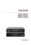
Lightware Device Controller software User’s Manual Lightware Device Controller User’s Manual Table of contents 1. INTRODUCTION ...................................................................................................................... 4 2. INSTALLING LIGHTWARE DEVICE CONTROLLER ............................................................ 4 2.1. 2.2. 2.3. THE NEW CONCEPT ............................................................................................................. 4 The normal install...................................................................................................... 4 The snapshot install .................................................................................................. 4 STEPS OF THE INSTALLATION IN CASE OF W INDOWS OS........................................................ 4 STEPS OF THE INSTALLATION IN CASE OF MAC OS X ............................................................. 7 3. UPGRADING THE LDC ........................................................................................................... 8 4. ESTABLISHING THE CONNECTION ..................................................................................... 9 5. LDC WINDOW ....................................................................................................................... 11 6. CROSSPOINT MENU ............................................................................................................ 12 6.1. 6.2. 6.3. 6.4. 6.5. 6.6. 6.7. 7. GRID VIEW (MX MATRICES) ............................................................................................... 12 Input and output board types .................................................................................. 13 Crosspoint operations ............................................................................................. 13 TILE VIEW (MX MATRICES)................................................................................................. 14 Port tiles .................................................................................................................. 15 View mode .............................................................................................................. 16 Changing crosspoint settings .................................................................................. 16 TILE VIEW (UMX EXTENDERS) ........................................................................................... 18 I/O PARAMETERS (OTHER LW EXTENDERS) ........................................................................ 19 PORT SETTINGS ................................................................................................................ 19 PRESETS .......................................................................................................................... 20 GENLOCK ......................................................................................................................... 21 EDID MENU ........................................................................................................................... 22 Changing emulated EDID ....................................................................................... 23 Learning an EDID ................................................................................................... 23 Exporting an EDID .................................................................................................. 23 Importing an EDID .................................................................................................. 23 EDID Summary window .......................................................................................... 23 Editing an EDID ...................................................................................................... 24 Creating an EDID (Easy EDID Creator) .................................................................. 24 Deleting EDID(s) ..................................................................................................... 24 8. SETTINGS MENU .................................................................................................................. 25 8.1. 8.2. 8.3. 8.4. 9. CONFIGURATION ............................................................................................................... 25 DEVICE INFORMATION ....................................................................................................... 26 STATUS ............................................................................................................................ 27 LOG ................................................................................................................................. 27 TERMINAL WINDOW ............................................................................................................ 29 10. SUPPORTING OF THE LDC ................................................................................................. 30 11. DOCUMENT REVISION HISTORY ....................................................................................... 30 Section 1. Introduction Page 3 / 30 1. Introduction The new version of the Lightware Device Controller (LDC) software got a unified look, contains some new features and many improvements, but all of the functions remained from the previous versions. It is also available for Windows and Mac OS X platform. An online update function was integrated into the LDC, which helps the users to have always the latest version. Important! All Lightware devices are supported by LDC (except 25G and MODEX, which have their own controller surface). Functions and features have been tested device by device deeply with the latest firmware package that was available in May 2014. As LDC takes the advantage of all new features implemented in the latest firmware, it is recommended to upgrade your devices to prevent any possible incompatibility issues. Detailed instructions about the upgrading can be found in the user’s manual of the device. In case of having any question about firmware upgrades please contact your local representative, or Lightware support team. (The global support contact is in chapter 10 on page 30.) 2. Installing Lightware Device Controller 2.1. The new concept There are two different ways to install the application: the normal and the snapshot install methods. The normal install Available for Windows and Mac OS X operating system. This is the default setting. An installer can update only this instance. Only one updateable instance can exist for all users. The updateable version does not contain the version number in its name. The snapshot install Available for Windows operating system. The snapshot instances cannot be updated. More than one different version can be installed for all users. The snapshot instances contain the version number in their name by default. 2.2. Steps of the installation in case of Windows OS Info: After the installation the Windows and the Mac application has the same looks and functionality. Step 1. Run Install_LDC_v1.3.0b0.exe If the User Account Control drops a pop-up message click Yes. Page 4 / 30 Section 1. Introduction Lightware Device Controller User’s Manual Step 2. A welcome window opens. Click Next. Step 3. Select the type of the installation. Here can be chosen the normal and the snapshot install as mentioned in the section 2.1 on page 4. Select the optional components then click Next. (Using the Normal install as the default value is highly recommended.) Step 4. Select the destination folder and click Next. (Using the default path is highly recommended.) Section 2. Installing Lightware Device Controller Page 5 / 30 Step 5. Select the Start Menu Folder and click Next. (Using the default folder is highly recommended. If the Start menu entries was not checked in the Step 2. this window will be skipped.) Step 6. Verify the settings and if they are correct click Install. (If not, click Back and change the setting.) Step 7. After the installation of the last component the Next button is activated. Click on it. Step 8. If the installation is complete, click Finish. (Uncheck the box if the running of the LDC will be delayed.) Page 6 / 30 Section 2. Installing Lightware Device Controller Lightware Device Controller User’s Manual 2.3. Steps of the installation in case of Mac OS X Info: After the installation the Windows and the Mac application has the same looks and functionality. Step 1. Mount the DMG file with double clicking on it. Step 2. Drag the LDC icon over the Applications icon to copy the program into the Applications folder. If you want to copy the LDC into another location just drag the icon over the desired folder. Info: This type of the installer is equal with the Normal install in case of Windows. (See section 2.1.1 on page 4.) This is an updateable version with the same attributes. Section 2. Installing Lightware Device Controller Page 7 / 30 3. Upgrading the LDC Step 1. Start the application. To run the controller software double clicks on the icon on the desktop or select proper shortcut from Start Menu All Programs Lightware Lightware Device Controller folder. The Device Discovery window appears automatically and the program checks the available updates on the Lightware website and opens the update window if the LDC found updates. The current and the update version number can be seen in the top of the window and they are shown in this window even with the snapshot install. Step 2. Set the desired update setting in the option section. a) If you do not want to check the update automatically, uncheck the circle, which contains the green tick. b) If the postponing is the desired choice for the updating, the reminder can be set for different duration with the drop-down list. c) If the proxy settings traverse the update process, set the proper values then click the OK button. Step 3. Click the Download update button to start the upgrading. Step 4. User can check updates manually by clicking the Check now button. Page 8 / 30 Section 3. Upgrading the LDC Lightware Device Controller User’s Manual 4. Establishing the connection The unit can be controlled from a Windows or OS X based computer using the LDC through Ethernet, USB or RS-232 connection. Step 1. Connect the desired device and the computer either via on of an interface, which is supported by the device. It can be: a) Serial port, with RS-232 cable b) Ethernet port, with LAN patch cable (via local network) c) Ethernet port, with LAN cross cable (direct connection) d) USB, with a mini USB cable Info: For the list of the available interfaces please read the user’s manual of the device. Info: If the connection is made through the device’s Ethernet port, be sure that the computer is in the same sub network as the device to be connected. Info: If the computer has multiple Ethernet connections (for example Wi-Fi and LAN connections are used simultaneously), you will have to know the IP address for the one that is used for controlling the device. Info: Upon connecting the device to the computer with USB, the operating system recognizes the device as a standard HID device and installs the required driver. Step 2. Start the application. (This is the same method as mentioned in chapter 3 on page 8 in the Step 1.) To run the controller software click double on the icon on the desktop or select proper shortcut from Start Menu All Programs Lightware Lightware Device Controller folder. The Device Discovery window appears automatically. Figure 4-1. Lightware Device Controller software startup If the connection has been made via Ethernet, the software picks all Ethernet interfaces, and shows the available Lightware devices on those ports. The device Section 4. Establishing the connection Page 9 / 30 type and the serial number are displayed automatically. Click the desired device, to highlight it. If the computer has more Ethernet ports (for example Wi-Fi and LAN connections are used simultaneously), you must select the one that is used to control the router from the drop-down list. If you are unsure which one to use, try to search for devices on all of them. Info: Some devices are able to make only one connection via Ethernet. If there is a live connection between the device and another computer, the device discovery will recognize it. In this case, the lines of these kinds of devices are grey instead of white, and there is no possibility to make connection with them. Figure 4-2. Ethernet connection If the connection has been made via serial port, the device type and serial number can be inquired by double clicking the appropriate port, or it can be highlighted with a single click. Figure 4-3. Serial connection If the connection has been made via USB port, the device type and the serial number are displayed automatically. Click the desired device, to highlight it. Figure 4-4. USB connection Step 3. Click on the Connect button to connect to the device Info: The controller software can communicate only with Lightware protocol. If the matrix router is set to other protocol, the software will ask to set the protocol. Info: If the router is not listed in the “available devices on Ethernet” box, try searching again, or see the troubleshooting guide in the user’s guide of the device. Info: Be sure that the firewall is not blocking the application! Info: For RS-232 connection, the router has to use 9600 or 57600 baud rate. The controller software determines the baud rate automatically. Page 10 / 30 Section 4. Establishing the connection Lightware Device Controller User’s Manual 5. LDC window When the LDC finds the hardware, it determines the product type, and the LDC starts with the default page. 1 2 3 4 5 6 7 Figure 5-1. Default start page of the LDC 1 Information ribbon This label shows the interface type, the name and the serial number of the connected device. If the device has more than one interface, the ribbon shows only that one, which has made the connection. The device discovery window can be started by clicking on this ribbon. 2 Crosspoint menu This menu contains both of the crosspoint areas, the preset area and the genlock settings. After connecting to a device, this menu appears by default with the Grid view. (For more information, see section 6 on page 12.) 3 EDID menu Advanced EDID Management can be accessed by selecting the EDID menu. (For more information, see section 7 on page 22.) 4 Settings menu The settings menu contains Hardware- and Software-related settings and information about connected device. (For more information, see section 8 on page 25.) 5 Tab selector ribbon The crosspoint and the settings menu contain more than one tabs. Click to the desired one to select it. The yellow line shows that which tab is the active one. 6 Working area The working area shows the content of the selected tab of the selected menu. The content depends on the device type, the menu and tab selections. 7 Terminal This general-purpose terminal is created mainly for testing and debugging purposes. (For more information, see section 9 on page 29.) Section 5. LDC window Page 11 / 30 6. Crosspoint menu The crosspoint menu contains the crosspoint state with Grid and Tile views, the Preset area and the Genlock functions. 6.1. Grid view (MX matrices) In this view, the current state of the crosspoint switch is displayed. The grid view depends on the device’s type, size and - in case of modular frames - the installed I/O boards. 1 8 2 3 7 4 5 6 Figure 6-1. Crosspoint array of a modular matrix Page 12 / 30 1 Input ports Each number represents an input port. If the window size does not allow to display all the ports, pages can be turned by the left and right arrow buttons of the navigator. 2 Type of input boards The color of the line shows what kind of input boards are installed (see section 6.1.1 on page 13.). 3 Connections Dark grey square means the port is not available. Light grey square means the port is available but no connection between the input and the output. White square means there is a connection between the input and the output port. 4 Type of output boards The color of the line shows what kind of output boards are installed (see section 6.1.1 on page 13.). 5 Output ports Each number represents an output port. If the window size does not allow to display all the ports, pages can be turned by the up and down arrow buttons of the navigator. 6 Mute buttons Outputs can be easily muted by clicking on the mute button. 7 Lock buttons For the prevention of the unwanted switching, outputs can be locked to any input. 8 Navigation buttons If the window size does not allow to display all the ports, pages can be turned by the arrow buttons of the navigator. Section 6. Crosspoint menu Lightware Device Controller User’s Manual Input and output board types Lightware matrix frames can be equipped with different types of boards. The colored bars below/next to the input/output ports display the type of the board in each slot. Whether it is an optical, a twisted pair or other kind of board, a different color represents its type. Info: Many Lightware devices are compact built systems, which do not have any separate boards. However, board types are shown to help identifying the ports. Legend for board types Unknown board or empty slot MX-HDMI-TP or MXD-HDMI-TP board MX-DVID board MX-DVI-OPT or MX-HDMI-OPT board MX-DVI-DL board MXD-UMX or MX-DVII-HDCP board MX-DVI-TP board MX-TPS board MX-HDMI or MX-DVI-HDCP board MX-3GSDI board Crosspoint operations Switching For making a connection click on the desired square. If there is no connection between the desired input and output (the square is dark grey), the mouse pointer becomes a hand (link pointer) before the clicking. If the output port is not locked, then the connection is made, the square becomes white and the cursor is changed back to a pointer. For example, input 33 is not connected to output 2 according to the first picture above. After the connection the square becomes light grey. Muting outputs Outputs can be easily muted by clicking on the button figured a crossed monitor beside the output. This means that no signal is present at this output. If mute is active, the color of the button’s background changes to white. Info: Switching muted outputs does not unmute them, muting remains active until mute button is clicked again. Info: Outputs can be disconnected from any inputs (by protocol command). In this case the crosspoint view will not show any white square for the disconnected output and the output will have no signal just like when muted. Click on a crosspoint square to connect the output again to an input. Locking outputs Outputs can be locked to any input. After locking an input to an output, no switching is permitted to this output unless it is unlocked again. If output lock is active, the color of the button’s background changes to white. Info: Loading a preset does not change either the lock state or the switch state of a locked output. If an output is locked to an input before preset loading it will also be locked to that input after preset loading, so locked outputs ignore the preset. Section 6. Crosspoint menu Page 13 / 30 6.2. Tile view (MX matrices) Tile view is a new feature of Lightware Device Controller. The new approach is to display the input and output ports by tiles. Each tile means an input or output port and additionally shows the most important port and signal information. Thus, user can check the status of many ports at the same time without clicking on a port or opening port settings window. Three display modes are defined in Tile view for MX matrices: View mode, Input switch mode and Output switch mode. 4 1 5 2 3 Figure 6-2. Tile view in Crosspoint menu Page 14 / 30 1 Input ports Each tile represents an input port. If window size does not allow to display all the ports, pages can be turned by the left and right arrow buttons. 2 Output ports Each tile represents an output port. If window size does not allow to display all the ports, pages can be turned by the left and right arrow buttons. 3 Page indicator Current page is displayed with green dot; if other pages exist, they are displayed with black dots. 4 Selected port Last selected port is displayed with yellow background on the port bar. Press the button to open port settings window. 5 Connected port(s) Those ports are listed (with white background) on the port bar, which are connected to the Selected port. Section 6. Crosspoint menu Lightware Device Controller User’s Manual Control buttons Mute Mute or unmute selected output port(s) Parameters Open port settings window Lock Lock or unlock selected output port(s) Select All Select all ports (only in output switch mode) View mode Activate View mode Deselect All Deselect all ports (only in output switch mode) Input switch Activate Input switch mode Autotake Toggle Autotake mode ON/OFF Take Execute crosspoint changes in Take mode Output switch Activate Output switch mode Port tiles The colors of the port tiles and the displayed icons represent different states and information about selected port: Output1 1 6 1 2 5 3 4 1 Port name 2 Port number 3 Board type 4 State indicators 5 Background color 6 Signal present (green), not present (grey) Following sections describe these meanings. Background colors (port state) The colors of the port tiles represent different states of the port as follows: Input1 Dark grey Port is not available (no board is installed) 1 Input2 2 Light grey Port is available U Output3 White Connected port 3 Input4 4 U Yellow Selected port State indicators (output ports) Following icons display different states of the output port: Icon Section 6. Crosspoint menu Icon is not displayed Icon is grey Icon is black No information is available about connection status Port is available but inactive Port is available and sink is connected (hotplug detected) - Port is unlocked Port is locked - Port is unmuted Port is muted Page 15 / 30 State indicators (input ports) Following icons display different states of the input port/signal: Icon Icon is not displayed No information is available about connection status [Signal type] Icon is grey Icon is black Port is available but inactive Port is available and source is connected (power +5V detected) No information is available Last detected signal type is displayed U – unknown signal D – DVI signal H – HDMI signal A – Analog signal S – SDI signal HDCP is not supported Signal is not encrypted with HDCP Signal is encrypted with HDCP Board types The types of the installed boards are displayed with a colored line on the bottom of the port. The following colors are defined: Unknown board or empty slot MX-HDMI-TP or MXD-HDMI-TP board MX-DVID board MX-DVI-OPT or MX-HDMI-OPT board MX-DVI-DL board MXD-UMX or MX-DVII-HDCP board MX-DVI-TP board MX-TPS board MX-HDMI or MX-DVI-HDCP board MX-3GSDI board View mode This mode was designed to display crosspoint state of a selected- and its connected port(s). View mode Info: Crosspoint settings cannot be changed in View mode but port settings are available. Changing crosspoint settings Crosspoint changes can be made in Input switch mode and Output switch mode. The working method is the same in both cases but the priority is different. Input switch mode The mode can be also named as ‘Input priority-mode’. In the mode an input port has to be selected at first then the connected output port(s) is/are shown. Thus, the output port(s) connected to the input port can be changed. Output switch mode The mode can be also named as ‘Output priority-mode’. In the mode an output port has to be selected at first then connected input port is shown. Thus, the output port connected to the input port can be changed. Info: Output ports can be (un)locked, (un)muted only in Output switch mode. Page 16 / 30 Section 6. Crosspoint menu Lightware Device Controller User’s Manual Switching operations Take mode If the Autotake button is outlined with black color Take mode is active. In Autotake Take mode any crosspoint change – (dis)connect ports to/from the previously selected port – is executed only after pressing the Take button. Following steps describe the process of the switching: Step 1. Press the desired Input switch or Output switch button to select switching mode. Step 2. Select the desired port; it will be highlighted with yellow color and displayed on the port bar on the right, too. Step 3. Connected port(s) is/are highlighted with white color and displayed on the port bar on the right, too. Step 4. Create the desired crosspoint settings by (de)selecting the ports; they will start to blink. Step 5. Press Take button to execute changes or Cancel to ignore the operations. Info: Take mode remains active until it is switched off. Selecting another view mode or menu does not change the Take/Autotake mode state. Autotake mode If the Autotake button is outlined with yellow color Autotake mode is Autotake active. In this mode any crosspoint change – (dis)connect ports to/from the previously selected port – is executed immediately after pressing the port button. Following steps describe the process of the switching: Step 1. Press the desired Input switch or Output switch button to select switching mode. Step 2. Select the desired port; it will be highlighted with yellow color and displayed on the port bar on the right, too. Step 3. Connected ports are highlighted with white color and displayed on the port bar on the right, too. Step 4. Create the desired crosspoint settings by (de)selecting the ports; the changes are executed immediately. Info: Autotake mode remains active until it is switched off. Selecting another view mode or menu does not change the Take/Autotake mode state. Port settings Press the desired port button on the port bar on the right. Parameters Info: Port settings of selected port are also available by pressing the Parameters button. Section 6. Crosspoint menu Page 17 / 30 6.3. Tile view (UMX extenders) When the LDC is connected to a UMX extender, only Tile view is defined in Crosspoint menu. The structure of Tile view is similar like the LDC is connected to an MX matrix. 1 2 3 4 5 6 Figure 6-3. Tile view (connected to a UMX extender) 1 Video input ports Each tile represents a video input port. The white-colored tile means the input that is switched to the output. 2 Audio input ports Each tile represents an audio input port. The white-colored tile means the input that is switched to the output. 3 View mode selector Crosspoint change cannot be done in View mode but input/output parameters are available. 4 Switch mode Crosspoint changes can be done by pressing the desired input port; it will be connected to the output immediately. 5 Input parameters Parameters of selected video input port are shown in a new window by pressing the button. 6 Output parameters Parameters of output port are shown in a new window by pressing the button. Info: No audio/video signal will present on the output port by pressing the selected audio/video port again. Page 18 / 30 Section 6. Crosspoint menu Lightware Device Controller User’s Manual 6.4. I/O parameters (other LW extenders) When LDC is connected to an extender like DVI-OPT-TX220-Pro or HDMI-TPS-TX95, I/O Parameters menu is displayed instead of Crosspoint menu. The tab contains minor information about input/output parameters. Press the button of the desired port to display port properties. Figure 6-4. I/O Parameters menu 6.5. Port settings The appearance of input/output port settings is device-dependent. If signal extender is connected, limited information and settings are available. For matrices and UMX extenders the input/output port settings are displayed in a new window with the available functions. By clicking on a port, a dialog window appears showing the parameters for the corresponding port. The exact look and the content of the setting window (signal parameters, frame detector, etc…) may depend on the type of the board or device because different boards/devices have different capabilities. Section 6. Crosspoint menu Page 19 / 30 6.6. Presets Preset operations can be done in Crosspoint submenu on the Preset tab at the devices, which support Preset operations, e.g. matrices. Each Lightware matrix switcher has 32 preset memories that can be loaded and saved at any time. Info: A preset setting stores a full configuration of all outputs, so preset loading have an effect on every output, except the locked ones. Figure 6-5. Presets tab A preset can be selected by pressing its button on the left. Preview preset (on the right) will show the crosspoint settings of input and output ports. Loading a preset Step 1. Select Preset tab from Crosspoint menu. Step 2. Select the preset memory (Preset1...Preset32) you want to load as the next crosspoint configuration. Step 3. Press Load button below Preset preview list. Now the preset is loaded. Step 4. The new I/O configuration is displayed in Grid view. Saving a preset Step 1. Make the desired crosspoint connections in Tile view or Grid view. Step 2. Select the preset memory (Preset1...Preset32) where you want to save your current crosspoint connections. Step 3. Press Save button below Preset preview list. Step 4. A confirmation message is displayed on the information bar; the preset is stored. Renaming a preset Step 1. Select the preset memory (Preset1...Preset32) you want to rename. Step 2. Type the desired name and press Rename Preset button; the new name is stored. Page 20 / 30 Section 6. Crosspoint menu Lightware Device Controller User’s Manual 6.7. Genlock If connected device supports Genlock, the fourth tab in Crosspoint menu displays the available settings and parameters. Info: Genlock settings of the devices may have minor differences; the window content can also be different. Figure 6-6. Genlock tab Section 6. Crosspoint menu Page 21 / 30 7. EDID menu Advanced EDID Management can be accessed by selecting EDID menu. Figure 7-1. EDID management There are two panels: left one contains Source EDIDs, right one contains Destination places where the EDIDs can be emulated. The list can be scrolled by mouse wheel or by grabbing and moving up and down. Control buttons Page 22 / 30 Save Exporting an EDID (save to a file) Upload Importing an EDID (load from a file) Executing EDID emulation or learning (Transfer button) Delete selected Info Opening selected EDID with Summary window Select All Edit Opening Advanced EDID Editor with selected EDID Deselect All EEC Opening Easy EDID Creator Deleting EDID (from user memory) Selecting all memory places in the right panel Selecting none of the memory places in the right panel Section 7. EDID menu Lightware Device Controller User’s Manual 7.1. EDID operations Changing emulated EDID Step 1. Select desired EDID list from one of the three sources by pressing its button. Step 2. Select an EDID from the Source panel that has to be emulated. Step 3. Press Emulated button above Destination panel. Step 4. Select desired port where the EDID has to be emulated (more ports can also be selected); the EDID(s) will be highlighted with yellow cursor. Step 5. Press Transfer button to change emulated EDID. Learning an EDID Info: The process is the same like changing emulated EDID; the only difference is the Destination panel: select ‘User’ button. Thus, one or more EDIDs can be copied into user memory either from factory memory or from a connected sink (Dynamic). Exporting an EDID Source EDID can be downloaded as a file (*.bin, *.dat or *.edid) to the computer. Step 1. Select desired EDID from the Source panel (highlight with yellow cursor). Step 2. Press Save button to open Save as dialog and download the file to the computer. Importing an EDID Previously saved EDID (*.bin, *.dat or *.edid file) can be uploaded to the user memory: Step 1. Press User button above Source panel. Step 2. Select a memory slot from the Source panel. Step 3. Press the Upload button below Source panel. Step 4. Browse the file in the opening window then press Open button. Browsed EDID is imported into the selected User memory. Info: The imported EDID overwrites the selected memory place even if it is not empty. EDID Summary window Select an EDID from Source panel and press Info button to display EDID summary. Figure 7-2. EDID Summary Section 7. EDID menu Page 23 / 30 Editing an EDID Select an EDID from Source panel and press Edit button to display Advanced EDID Editor window. The editor can read and write all descriptors, which are defined in the standards, including the additional CEA extensions. Any EDID from the device’s memory or a saved EDID file can be loaded in the editor. The software resolves the raw EDID, and displays it as readable information to the user. All descriptors can be edited, and saved in an EDID file, or uploaded to the User memory. Figure 7-3. Advanced EDID Editor Creating an EDID (Easy EDID Creator) Since above mentioned Advanced EDID Editor needs more complex knowledge about EDID, Lightware introduced a wizard-like interface for fast and easy EDID creation. With Easy EDID Creator it is possible to create custom EDIDs in four simple steps. By clicking on the EEC button below Source panel, Easy EDID Creator is opened in a new window. Deleting EDID(s) The EDID(s) from User memory can be deleted as follows: Step 1. Press User button above Destination panel. Step 2. Select desired memory slot(s); more ports can be selected. Use Select All and Deselect All buttons according to the needs. The EDID(s) will be highlighted with yellow cursor. Step 3. Press Delete selected button to delete the EDID(s). Page 24 / 30 Section 7. EDID menu Lightware Device Controller User’s Manual 8. Settings menu The menu contains Hardware- and Software-related settings and information about connected device. The content of the tabs is also device-dependent. 8.1. Configuration Settings about establishing the connection to the desired device are available on this tab. Figure 8-1. Configuration tab IP Configuration The IP address and TCP/IP port can be set up here. Obtain IP address automatically By selecting the Obtain IP address automatically option, the device gets the IP address from the DHCP server on the LAN, or if DHCP server is not present, it gets an AutoIP address from 169.254.xxx.xxx domain. Set BOOTP, DHCP and AutoIP settings according to your network requirements. Always press the Apply settings button to save changes. Info: Load default button restores the default network settings (fix IP) to the device: IP Address: 192.168.254.254, Subnet Mask: 255.255.0.0, Default Gateway: 0.0.0.0. Info: When serial port is used for connection, these settings cannot be changed. Fix IP configuration In this case, connected device has an IP address configuration set up by the user/administrator. Depending on modified settings, you might need to restart the device and the Control Software. Always press the Apply settings button to save changes. Info: Load default button restores the default network settings (fix IP) to the device: IP Address: 192.168.254.254, Subnet Mask: 255.255.0.0, Default Gateway: 0.0.0.0. Info: When serial port is used for connection these settings cannot be changed. Section 8. Settings menu Page 25 / 30 TCP Port Configuration Devices can be accessed via this TCP/IP port number with TCP connection. Port number can be modified to any number between 1025 and 65535 except the followings: 9999, 14000 - 14009, 30704, and 30718. To use a matrix with Barco Encore set port to 23. To use a matrix with Vista Spyder set port to 10001. Always press the Apply settings button to save changes. Serial Port Configuration The Baud rate for serial connection can be set by the drop-down list: 9600, 19200, 38400, 57600, or 115200. Always press the Apply settings button to save changes. 8.2. Device information Basic information about connected device and installed cards are listed on this tab. Figure 8-2. Device information tab Page 26 / 30 Section 8. Settings menu Lightware Device Controller User’s Manual 8.3. Status The voltage levels, fan speeds and temperature measured by the CPU of the device are shown. Press the Refresh button to show/update values. Figure 8-3. Status tab 8.4. Log Events logged by the device and report generators can be found on Log tab. There are two sections: Report and Error log viewer. Figure 8-4. Log tab Section 8. Settings menu Page 27 / 30 Report section LDC is able to collect information from the device and save it to a report file. This information package can be sent to Lightware support team when a problem may arise with the device. Step 1. Press the red button: Generate report file. Step 2. LDC collects the needed information; this may take up to 5 minutes. Step 3. After generating the report the ‘Save as’ dialog box appears. Select the folder where you want to save the report file. The default file name can be changed. The report contains the following device-dependent information: (if available) Current command protocol, Device type and serial number, Current crosspoint state, Firmware versions of all the internal controllers, Installed I/O board types and versions, Hardware health status, All EDID headers and status (emulated, dynamic, factory, user), Basic error list, log file list and last detailed error log. Open custom report from file The Controller Software is able to send a custom command file to certain devices (matrices). The command file can be generated by Lightware support. This is needed when some special commands has to be used for configuring the device or troubleshooting. Info: This function is only for special troubleshooting cases. Error log viewer (MX matrices, UMX extenders) Log files saved by the devices can be downloaded and viewed with this function. The columns in the list are the followings: error level, time, error code, error parameter, processor task identifier, occurrences and extra information. The device creates a new error log file every time it is started except if a log file exists for that day. The software allows selecting only those months and days, which have a log. Step 1. Select the month of the error log. Step 2. Select the day. Step 3. The error log is downloaded and shown as a table. Step 4. The error log can be saved in a CSV file on the computer by the Export to CSV file button. Logs can be deleted one-by-one or all the logs at the same time with the Delete all logs and Delete this log buttons. 8.5. User preferences (only in case of MX matrices) The tab shows some settings in connection with the LDC displaying/working mode. Figure 8-5. User preferences tab Page 28 / 30 Section 8. Settings menu Lightware Device Controller User’s Manual 9. Terminal window The terminal is created mainly for testing and debugging purposes. The terminal is available via serial RS-232, TCP/IP LAN or USB connection. The command text can be typed directly. Press Terminal button in the right bottom corner to open the window. Figure 9-1. Terminal window Commands are automatically surrounded by framing brackets by default. Every sent command is red-colored and gets a ‘>’ prefix. Received responses are blue-colored and starts with ‘<’. The timecode in every row shows the exact time when the command was sent or the response received. If the Command framing checkbox is unchecked, you can send multiple commands together, however in this case you have to type in the framing brackets manually. If the Autoscroll checkbox is checked, the window is scrolled down automatically when a new row is added. The window can be emptied by pressing the Clear button. Section 9. Terminal window Page 29 / 30 10. Supporting of the LDC In case of having any question or observing any malfunction, please call your local representative, or contact Lightware at Lightware Visual Engineering LLC. Peterdy 15, Budapest H-1071, HUNGARY E-mail: [email protected] 11. Document revision history Document Release Date Changes Editor Rev. 1.0 21-05-2014 Initial version Zsolt Marko Laszlo Zsedenyi Rev. 1.1 29-05-2015 Minor updates to LDC v1.3.0 Laszlo Zsedenyi Page 30 / 30 Section 10. Supporting of the LDC