Download MODEX-OPTS, MODEX-OPTM User`s manual

Transcript
MODEX-F15-OPTS-TX
MODEX-F15-OPTM-TX
MODEX-F15-OPTS-RX
MODEX-F15-OPTM-RX
User’s Manual
MODEX-F15-OPTS, MODEX-F15-OPTM
User’s Manual
SAFETY INSTRUCTIONS
Class I apparatus construction. This equipment must be used with a main power system
with a protective earth connection. The third (earth) pin is a safety feature, do not bypass
or disable it.
This equipment should be operated only from the power source indicated on the product.
To disconnect the equipment safely from power, remove the power cord from the rear of
the equipment, or from the power source. The MAINS plug is used as the disconnect
device, the disconnect device shall remain readily operable.
There are no user-serviceable parts inside of the unit. Removal of the top cover will expose
dangerous voltages. To avoid personal injury, do not remove the top cover. Do not operate
the unit without the cover installed.
The apparatus shall not be exposed to dripping or splashing and that no objects filled with
liquids, such as vases, shall be placed on the apparatus.
The apparatus must be safely connected to multimedia systems. Follow instructions
described in this manual.
WEEE
( W as te E l e c tr ic a l & E lec tr on ic Eq u ipm en t )
Correct Disposal of This Product
This marking shown on the product or its literature, indicates that it should not be disposed
with other household wastes at the end of its working life. To prevent possible harm to the
environment or human health from uncontrolled waste disposal, please separate this from
other types of wastes and recycle it responsibly to promote the sustainable reuse of
material resources.
Household users should contact either the retailer where they purchased this product, or
their local government office, for details of where and how they can take this item for
environmentally safe recycling.
Business users should contact their supplier and check the terms and conditions of the
purchase contract. This product should not be mixed with other commercial wastes for
disposal.
Caution: Laser product
This laser product is designated as Class 1M, wavelengths are 850 nm, 1310 nm, 1490
nm, 1550 nm.
LASER RADIATION
DO NOT VIEW DIRECTLY WITH
OPTICAL INSTRUMENTS
CLASS 1M LASER PRODUCT
Section 1. Introduction
Page 3 / 120
DECLARATION OF CONFORMITY
We,
Lightware Kft. 1071 Budapest Peterdy str. 15 HUNGARY
as manufacturer declare, that the products
MODEX-F15-OPTS-TX
MODEX-F15-OPTM-TX
MODEX-F15-OPTS-RX
MODEX-F15-OPTM-RX
( Computer Monitor Extender )
in accordance with the EMC Directive 2004/108/EC and the Low Voltage Directive
2006/95/EEC are in conformity with the following standards:
EMI/EMC .................... EN 55103-1 E3, EN 55103-2
Safety .......................................... EN 60065 Class I
Date:
1 April 2014
Name:
Gergely Vida ( Managing Director )
Signed:
Page 4 / 120
Section 1. Introduction
MODEX-F15-OPTS, MODEX-F15-OPTM
User’s Manual
TABLE OF CONTENTS
1.
INTRODUCTION ...................................................................................................................... 9
1.1.
1.2.
1.3.
1.4.
2.
BOX CONTENTS................................................................................................................... 9
DESCRIPTION...................................................................................................................... 9
FEATURES ........................................................................................................................ 10
APPLICATIONS .................................................................................................................. 11
CONTROLS AND CONNECTIONS....................................................................................... 12
2.1. MODEX CONCEPT............................................................................................................ 12
2.2. FRAMES ........................................................................................................................... 13
2.3. REAR VIEW ....................................................................................................................... 15
2.4. MEDIA CONNECTORS ......................................................................................................... 15
2.5. VIDEO MODULES ............................................................................................................... 16
2.6. INTERFACE MODULES ........................................................................................................ 17
2.7. ELECTRICAL CONNECTIONS ............................................................................................... 18
2.7.1. Fiber optical connectors .......................................................................................... 18
2.7.2. HDMI inputs and outputs ........................................................................................ 19
2.7.3. DVI inputs and outputs............................................................................................ 19
2.7.4. DisplayPort input and output ................................................................................... 20
2.7.5. BNC connectors (SDI) ............................................................................................ 20
2.7.6. Ethernet port ........................................................................................................... 20
2.7.7. Analog stereo audio (balanced) .............................................................................. 21
2.7.8. S/PDIF digital audio input and output ..................................................................... 21
2.7.9. IR connectors .......................................................................................................... 21
2.7.10. Neutrik power connector ......................................................................................... 22
2.7.11. RS-232 / RS-422 port ............................................................................................. 23
3.
TECHNOLOGIES................................................................................................................... 24
3.1. UNDERSTANDING EDID..................................................................................................... 24
3.2. ADVANCED EDID MANAGEMENT ........................................................................................ 25
3.3. HDCP MANAGEMENT ........................................................................................................ 25
3.3.1. Protected and unprotected content ......................................................................... 25
3.3.2. Real life examples................................................................................................... 26
4.
INSTALLATION ..................................................................................................................... 27
4.1. CONNECTING DEVICES ...................................................................................................... 27
4.2. SERIAL DEVICES................................................................................................................ 28
4.2.1. General information about serial communication ................................................... 28
4.2.2. Example connection diagrams ................................................................................ 28
4.3. MOUNTING OPTIONS .......................................................................................................... 29
4.3.1. Rack shelf mounting (with 1U high rack shelf) ....................................................... 29
4.3.2. Truss mounting (with Mounting bracket V2) ........................................................... 29
4.3.3. Through furniture mounting (with Mounting bracket V2) ........................................ 29
5.
FRONT PANEL OPERATIONS ............................................................................................. 30
5.1. FRONT PANEL MENU .......................................................................................................... 30
5.2. SETTINGS MENU................................................................................................................ 31
5.2.1. System settings ....................................................................................................... 31
5.2.2. Network settings ..................................................................................................... 32
5.3. MODULES MENU................................................................................................................ 33
5.3.1. Video module .......................................................................................................... 33
5.3.2. Optical module ........................................................................................................ 34
5.3.3. Audio module .......................................................................................................... 34
5.3.4. Serial & IR module .................................................................................................. 35
5.3.5. Front module ........................................................................................................... 35
5.4. CROSSPOINTS MENU ......................................................................................................... 35
5.5. EDID MENU (TRANSMITTER) .............................................................................................. 35
5.6. EDID MENU (RECEIVER) .................................................................................................... 36
5.7. PRESETS MENU................................................................................................................. 36
Section 1. Introduction
Page 5 / 120
5.7.1.
5.7.2.
6.
Saving a preset ....................................................................................................... 36
Applying a preset .................................................................................................... 36
WEB CONTROL – USING THE BUILT-IN WEBSITE .......................................................... 37
6.1. NETWORK STRUCTURE ...................................................................................................... 37
6.1.1. IP settings ............................................................................................................... 37
6.1.2. Establishing the connection .................................................................................... 37
6.2. LAYOUT OF BUILT-IN WEB................................................................................................... 38
6.3. CROSSPOINT MENU ........................................................................................................... 39
6.3.1. Video crosspoint ..................................................................................................... 40
6.3.2. Audio crosspoint ..................................................................................................... 40
6.3.3. Infra crosspoint ....................................................................................................... 41
6.3.4. Serial crosspoint ..................................................................................................... 42
6.4. MODULE PROPERTIES AND SETTINGS ................................................................................. 44
6.4.1. Optical link quality ................................................................................................... 44
6.4.2. Video modules ........................................................................................................ 44
6.4.3. Audio modules ........................................................................................................ 44
6.5. PORT PROPERTIES AND SETTINGS...................................................................................... 47
6.5.1. Analog audio input port ........................................................................................... 48
6.5.2. Analog audio output port ......................................................................................... 48
6.5.3. HDMI output port ..................................................................................................... 48
6.5.4. HDMI input port ....................................................................................................... 49
6.5.5. SDI port ................................................................................................................... 49
6.5.6. IR port ..................................................................................................................... 50
6.5.7. RS-232 port ............................................................................................................. 50
6.6. EDID MENU ...................................................................................................................... 51
6.6.1. About EDID memory (transmitter) .......................................................................... 51
6.6.2. EDID types .............................................................................................................. 51
6.6.3. Advanced EDID Management ................................................................................ 52
6.6.4. Sources and Destinations ....................................................................................... 52
6.6.5. Changing emulated EDID ....................................................................................... 53
6.6.6. Learning an EDID ................................................................................................... 53
6.6.7. Exporting an EDID .................................................................................................. 53
6.6.8. Importing an EDID .................................................................................................. 53
6.6.9. EDID info ................................................................................................................. 54
6.6.10. Creating an EDID .................................................................................................... 54
6.6.11. Editing an EDID ...................................................................................................... 55
6.6.12. Deleting EDID(s) ..................................................................................................... 55
6.7. CONTROL MENU ................................................................................................................ 55
6.7.1. Ethernet tab ............................................................................................................ 55
6.7.2. USB tab ................................................................................................................... 56
6.8. EVENT MANAGER .............................................................................................................. 56
6.8.1. The event area ........................................................................................................ 57
6.8.2. Wizard mode ........................................................................................................... 58
6.8.3. Advanced mode ...................................................................................................... 59
6.8.4. Save, load or clear an event ................................................................................... 60
6.9. SETTINGS MENU................................................................................................................ 61
6.9.1. Core tab .................................................................................................................. 61
6.9.2. Network tab ............................................................................................................. 61
6.9.3. Status tab ................................................................................................................ 62
6.9.4. System log tab ........................................................................................................ 62
6.9.5. Lock tab .................................................................................................................. 63
6.9.6. Presets tab .............................................................................................................. 64
6.10. CONFIGURATION CLONING (BACKUP TAB) ........................................................................... 66
6.10.1. Cloning steps in a nutshell ...................................................................................... 66
6.10.2. Save the settings of the extender (Backup) ............................................................ 66
6.10.3. Upload the settings to a device (Restore)............................................................... 67
6.10.4. Network settings ..................................................................................................... 67
6.11. ADVANCED VIEW ............................................................................................................... 68
7.
PROGRAMMER’S REFERENCE .......................................................................................... 70
Page 6 / 120
Section 1. Introduction
MODEX-F15-OPTS, MODEX-F15-OPTM
User’s Manual
7.1. LW3 PROTOCOL – OVERVIEW............................................................................................ 70
7.1.1. Elements of tree structure ....................................................................................... 70
7.1.2. Escaping ................................................................................................................. 72
7.1.3. Error messages ....................................................................................................... 73
7.1.4. Prefix summary ....................................................................................................... 73
7.2. COMMANDS ...................................................................................................................... 74
7.2.1. Get all children of a node ........................................................................................ 74
7.2.2. Get all properties and methods of a node............................................................... 74
7.2.3. Get all child nodes, properties and methods of a node .......................................... 75
7.2.4. Set command .......................................................................................................... 75
7.2.5. Invocation ................................................................................................................ 76
7.2.6. Subscription ............................................................................................................ 76
7.2.7. Notifications about the changes of the properties .................................................. 78
7.2.8. Signature ................................................................................................................. 78
7.2.9. Manual .................................................................................................................... 79
7.2.10. Formal definitions .................................................................................................... 79
7.3. LW3 PROTOCOL TREE ....................................................................................................... 79
7.3.1. /REMOTE ................................................................................................................ 80
7.3.2. /PRESETS .............................................................................................................. 80
7.3.3. /MANAGEMENT/ .................................................................................................... 80
7.3.4. /EDID....................................................................................................................... 81
7.3.5. /MEDIA .................................................................................................................... 81
7.3.6. /SYS ........................................................................................................................ 81
7.4. VIDEO PORT AND CROSSPOINT SETTINGS ........................................................................... 81
7.4.1. Query the video crosspoint setting ......................................................................... 81
7.4.2. Query the status of source ports ............................................................................. 82
7.4.3. Mute an input port ................................................................................................... 83
7.4.4. Unmute an input port .............................................................................................. 83
7.4.5. Lock an input port ................................................................................................... 83
7.4.6. Unlock an input port ................................................................................................ 83
7.4.7. Mute the output ....................................................................................................... 83
7.4.8. Unmute the output .................................................................................................. 84
7.4.9. Lock the output ....................................................................................................... 84
7.4.10. Unlock the output .................................................................................................... 84
7.5. AUDIO PORT AND CROSSPOINT SETTINGS ........................................................................... 84
7.5.1. Query the audio crosspoint setting ......................................................................... 84
7.5.2. Switching audio input .............................................................................................. 85
7.6. RS-232 PORT CONFIGURATION.......................................................................................... 85
7.6.1. BAUD rate setting ................................................................................................... 85
7.6.2. Databit setting ......................................................................................................... 85
7.6.3. Stopbit setting ......................................................................................................... 85
7.6.4. Parity setting ........................................................................................................... 86
7.7. NETWORK CONFIGURATION ............................................................................................... 86
7.7.1. Query the DHCP state ............................................................................................ 86
7.7.2. Change the DHCP state ......................................................................................... 86
7.7.3. Query the IP address (dynamic) ............................................................................. 86
7.7.4. Change the IP address (static) ............................................................................... 86
7.7.5. Query the subnet mask (static network mask) ....................................................... 87
7.7.6. Change the subnet mask (static) ............................................................................ 87
7.7.7. Query the gateway address (static) ........................................................................ 87
7.7.8. Change the gateway address (static) ..................................................................... 87
7.8. EVENT SETTINGS (CONDITIONS AND ACTIONS) .................................................................... 87
7.8.1. Set the source node (condition) .............................................................................. 88
7.8.2. Set the source property (condition) ......................................................................... 88
7.8.3. Set the value of the source property (condition) ..................................................... 88
7.8.4. Set the target node (action) .................................................................................... 88
7.8.5. Set the target property (action) ............................................................................... 89
7.8.6. Set the value of the target property (action) ........................................................... 89
7.9. EDID MANAGEMENT.......................................................................................................... 89
7.9.1. Query the emulated EDIDs ..................................................................................... 89
7.9.2. Query the validity of a dynamic EDID ..................................................................... 89
Section 1. Introduction
Page 7 / 120
7.9.3.
7.9.4.
7.9.5.
7.9.6.
7.9.7.
8.
Query a user EDID header ..................................................................................... 89
Emulating an EDID to an input port ........................................................................ 90
Copy an EDID to user memory ............................................................................... 90
Deleting an EDID from user memory ...................................................................... 90
Resetting emulated EDIDs ..................................................................................... 90
FIRMWARE UPGRADE......................................................................................................... 91
8.1. SHORT INSTRUCTIONS ....................................................................................................... 91
8.2. DETAILED INSTRUCTIONS................................................................................................... 91
8.2.1. Get the firmware pack and the LDU application ..................................................... 91
8.2.2. Install the LDU application ...................................................................................... 91
8.2.3. Mac OS X install ..................................................................................................... 93
8.2.4. Upgrading the LDU ................................................................................................. 94
8.2.5. Connect the computer to the MODEX device(s) .................................................... 94
8.2.6. Start the LDU and follow the instructions shown on the screen ............................. 95
9.
SPECIFICATIONS ................................................................................................................. 99
9.1. FRAMES ........................................................................................................................... 99
9.1.1. MODEX-F15 frames ............................................................................................... 99
9.2. MEDIA CONNECTORS ....................................................................................................... 100
9.2.1. MODEX-F15-OPTS and MODEX-F15-OPTM ...................................................... 100
9.3. VIDEO & AUDIO MODULES................................................................................................ 101
9.3.1. MODEX-AV-DVIDL-IM .......................................................................................... 101
9.3.2. MODEX-AV-DVIDL-OM ........................................................................................ 101
9.3.3. MODEX-AV-HDMI-DVI-IM .................................................................................... 102
9.3.1. MODEX-AV-HDMI-DVI-4K-IM .............................................................................. 102
9.3.2. MODEX-AV-HDMI-OM ......................................................................................... 103
9.3.3. MODEX-AV-HDMI-4K-OM .................................................................................... 103
9.3.4. MODEX-AV-DP-IM ............................................................................................... 104
9.3.5. MODEX-AV-DP-OM.............................................................................................. 104
9.3.6. MODEX-AV-3GSDI-IM.......................................................................................... 105
9.3.7. MODEX-AV-DVI-OM............................................................................................. 105
9.3.8. MODEX-AV-DVI-IM .............................................................................................. 106
9.3.9. MODEX-AV-DVI-4K-OM ....................................................................................... 107
9.3.10. MODEX-AV-HDMI-DVI-4K-OM ............................................................................ 107
9.4. INTERFACE MODULES ...................................................................................................... 108
9.4.1. MODEX-IF-RS232 ................................................................................................ 108
9.4.2. MODEX-IF-2xRS232 ............................................................................................ 108
9.4.3. MODEX-IF-RS232-RS422 .................................................................................... 108
9.4.4. MODEX-IF-RS232-IR ........................................................................................... 109
9.4.5. MODEX-IF-ETH .................................................................................................... 109
9.4.6. MODEX-IF-AUDIN ................................................................................................ 109
9.4.7. MODEX-IF-AUDOUT ............................................................................................ 110
9.4.8. MODEX-IF-AUD .................................................................................................... 110
9.4.9. MODEX-IF-4ETH .................................................................................................. 110
9.4.10. MODEX-IF-ETH-ECN ........................................................................................... 111
10. TROUBLESHOOTING ......................................................................................................... 112
11. APPENDIX ........................................................................................................................... 115
11.1.
11.2.
11.3.
11.4.
11.5.
MECHANICAL DRAWINGS.................................................................................................. 115
FACTORY DEFAULT SETTINGS .......................................................................................... 116
FACTORY EDID LIST ....................................................................................................... 117
CONTENT OF THE BACKUP FILE ........................................................................................ 118
THE NEW FEATURES OF MODEX HW V3.0 (CM-1004) .................................................... 119
12. VERSION APPLICABILITY ................................................................................................. 120
13. WARRANTY ........................................................................................................................ 120
14. DOCUMENT REVISION HISTORY ..................................................................................... 120
Page 8 / 120
Section 1. Introduction
MODEX-F15-OPTS, MODEX-F15-OPTM
User’s Manual
1. Introduction
Thank you for choosing MODEX, Lightware’s Modular Extender family. The MODEX family
is a hybrid, modular and multi-layer group of extenders supporting AV and broadcast
industry’s formats. Capable of extending digital and analog audio and video, USB KVM,
Ethernet and control signals like RS-232, RS-422 or Infrared.
1.1. Box contents
MODEX transmitter or
receiver
Power cable with IEC
connector
Power cable with Neutrik
powerCON connector and
additional chuck1
UTP patch cable (1 m)
Rubber feet with screws
and washers (4x)
Phoenix® Combicon
5-pole connector2
Infrared transmitter with TS
male connector3
Infrared receiver with TRS
male connector3
1.2. Description
The technology built into the MODEX family breaks many standard limitations allowing 30
meters DVI cable on input, Advanced EDID Management, Pixel Accurate Reclocking, LAN
and RS-232/RS-422 control.
The half unit extender allows one video & audio module and two interface modules (each
can be the same or different type). The front panel has an additional 10/100 Mbps Ethernet
port (with full functionality, but can be used as control interface) and USB KVM connectors
(transmitter has one USB-B for the computer; receiver has two USB-A connectors for the
keyboard and mouse). Keyboard and mouse functions are emulated by the extender and
no USB enumeration occurs while operator switching. A computer is not aware when a
keyboard or mouse has been changed.
MODEX includes a family of long distance transmitters and receivers for sending and
receiving video, audio, RS-232 and IR control, USB KVM and Ethernet over a single fiber
cable. Media connector, the heart of the MODEX determines the signal transportation type
as well as the direction (the unit is a transmitter or receiver).
The MODEX is fully compatible with the 25G hybrid architecture.
1
For the following media connectors: MODEX-CON-OPTS-NT-PCN and MODEX-CON-OPTM-NT-PCN.
For the following modules: MODEX-IF-AUDIN and MODEX-IF-AUDOUT (1-1 pc.), MODEX-IF-AUD (2 pcs.)
3 For the following module: MODEX-IF-RS232-IR
2
Section 1. Introduction
Page 9 / 120
1.3. Features4
 Variable A/V modules – MODEX can be supplied with different type of Video ports both on
transmitter and receiver side: HDMI, DVI, DisplayPort and 3G-SDI connectors. To increase
the flexibility, transmitter and receiver can be assembled with different type of video ports.
 Wide range of interface modules – There are two slots in the extenders where interface modules
can be installed. Numerous modules are available which contains Analog-, S/PDIF audio
connectors, Ethernet-, RS-232- and Infrared ports in many combinations.
 Physical modules with different connectors – MODEX can be ordered with many type of power
connectors and optical connectors.
 LW3 protocol – The devices use the new LW3 protocol which is based on a well-structured protocol
tree. Wide range of properties and methods allow to get information about the ports or
create controlling commands.
 25G compatibility – Thanks for the LW3 protocol and the design of MODEX and 25G matrix, the
devices are compatible and able to send controlling commands to each other.
 Signal transmission up to 10 km – MODEX with single mode optical unit is able to transmit the
signal to 10 km distance.
 Single fiber technology – MODEX-F15-OPTS and -OPTM extenders give optical transmission over
a single or duplex fiber; equipped with a Neutrik OpticalCON or industrial grade connector
but both can be used with LC fiber cable.
 Pixel accurate reclocking – The video output on the receiver has a clean, jitter free signal,
eliminating signal instability and distortion caused by long cables or connector reflections.
 Built-in web page – Easy access from a Web browser to control and configure the MODEX pair.
 Controlling functions with the Event manager – MODEX can be configured to perform an action
if a condition appears. E.g. if a signal is present on an input, a command is sent via the
RS-232 port.
 Advanced EDID Management – User can emulate any EDID on video input ports, read out and
store any monitor’s EDID.
 HDCP enable / disable – MODEX extenders are HDCP-capable ones. To display unprotected
content on a non-HDCP capable sink, HDCP can be disabled via the front panel menu or
from a web browser by the built-in web page.
 USB K+M – Connected USB HID devices (e.g. keyboard, mouse) are extended from transmitter to
receiver thus a computer can be remote controlled.
 Simple and fast Firmware upgrade –Lightware Device Updater helps to upgrade many devices
together. The process is easier than before: the extenders use the same firmware package.
 Front panel control – EDID emulation, Network settings, Preset handling and the most important
module settings are available on LCD-based menu with navigation buttons.
 Half-rack sized – The housing of the extenders fits to the industrial standard rack dimension: 1 rack
unit high and half rack wide. Further accessories help to mount the units easily.
 Built-in universal power supply – The extenders are equipped with a built-in universal power
supply, which accepts AC voltages from 100 to 240 Volts with 50 or 60 Hz line frequency.
 Front panel LEDs – Audio, Video, Optical Link and PSU LEDs to get immediate feedback about the
signals and link status.
4
The available features depend on the modules installed into the given MODEX product.
Page 10 / 120
Section 1. Introduction
MODEX-F15-OPTS, MODEX-F15-OPTM
User’s Manual
1.4. Applications
Figure 1-1. Integrated system
Figure 1-2. Stand-alone application
Section 1. Introduction
Page 11 / 120
2. Controls and connections
2.1. MODEX concept
Code sequence
Each MODEX unit has a 15-character-long code sequence which identifies the modules
built in the frame. The code sequence consists of 5x3 blocks of characters. The
3-character-long blocks are the last three characters of a module’s part code (this code is
also painted on the module/frame).
The following example represents the structure of the code sequence:
The module code – that is displayed in idle state – of above MODEX unit is:
108227410715721
Interface module (D)
Interface module (E)
Video module (B)
Media connector
Frame
108: (9161 0108) MODEX-F15-OPTS-TX
Frame
227: (9161 0227) MODEX-CON-NT-OPTS
Media connector
410: (9161 0410) MODEX-AV-HDMI-DVI-4K-IM
Video module (B)
715: (9161 0715) MODEX-IF-RS232-IR
Interface module (E)
721: (9161 0721) MODEX-IF-AUD
Interface module (D)
Info: The order of the modules and codes are determined by Lightware.
Module layout
The layout of the modules is fixed so as the order of
the module codes. B, D and E letters determine the
module positions which help to identify them in LW3
protocol.
C means the physical module (PHY), which is
integrated into the Core module in MODEX-F15OPT extenders.
Media
connector
Video
(B)
The letters are also displayed in the built-in website
in the Settings menu, Status submenu, see section
6.9.3 on page 62, and Lock submenu, see in section
6.9.5 on page 63.
Interface Interface
(D)
(E)
Core
PHY
(C)
USB/Eth
Front Panel
Page 12 / 120
Section 2. Controls and connections
MODEX-F15-OPTS, MODEX-F15-OPTM
User’s Manual
2.2. Frames
Info: The LCD of MODEX units with hardware v3.0 contains light blue backlight. Older MODEX
units contain light green backlight.
HW v3.0 –
HW v2.2
Info: See more information about the differences in section 11.5 on page 119.
Transmitter front view
Info: MODEX-F15-OPTS frames can be seen on the photos which are almost the same as
MODEX-F15-OPTM frames. Their housing contains just two differences: the ‘OPTM’
designation and the part number.
Ethernet 1
2 Status LEDs
5 USB K+M
Menu navigation 3
6
Menu display
4 PSU LEDs
7 Reset
1
Ethernet
Locking RJ45 socket. Remote control port for connecting the unit
to Local Area Network (LAN).
2
Status LEDs
Audio LED lights green when the audio transfer is active. Video
LED indicates correct video transmission. RX DETECT LED is
green when low speed handshake of the extenders is complete.
OPTS LINK LED lights when optical link is active.
3
Menu navigation
Up, down, left, right, enter and escape buttons for menu
navigation.
4
PSU LEDs
CPU live LED blinks to indicate normal operation. +5V and +3.3V
LEDs light green when the extender is powered on.
5
USB K+M
USB connection to HOST (Computer) unit via USB B-type
connector.
6
Menu display
Displays status information and menu operation on the LCD with
2x16 characters.
7
Reset
Reset button reboots the extender. This is the same as
disconnecting from power source and reconnecting again.
Transmitter frames
Frame type
Part nr.
MODEX-F15-OPTS-TX
9161 0108
MODEX-F15-OPTM-TX
9161 0110
Section 2. Controls and connections
Page 13 / 120
Receiver front view
Info: MODEX-F15-OPTS frames can be seen on the photos which are almost the same as
MODEX-F15-OPTM frames. Their housing contains just two differences: the ‘OPTM’
designation and the part number.
Ethernet 1
2 Status LEDs
Menu navigation 3
6 Menu display
USB ports 5
4 PSU LEDs
7 Reset
1
Ethernet
Locking RJ45 socket. Remote control port for connecting the unit
to Local Area Network (LAN).
2
Status LEDs
Audio LED lights green when the audio transfer is active. Video
LED indicates correct video transmission. TX DETECT LED is
green when low speed handshake of the extenders is complete.
OPTS LINK LED lights when optical link is active.
3
Menu navigation
Up, down, left, right, enter and escape buttons for menu
navigation.
4
PSU LEDs
CPU live LED blinks to indicate normal operation. +5V and +3.3V
LEDs light green when the extender is powered on.
5
USB ports
USB K+M ports for HID 1 devices (preferably Keyboard and
mouse). See more information in section 6.7.2 on page 56.
6
Menu display
Displays status information and menu operation on the LCD with
2x16 characters.
7
Reset
Reset button reboots the extender. This is the same as
disconnecting from power source and reconnecting again.
Receiver frames
Frame type
1
Part nr.
MODEX-F15-OPTS-RX
9161 0109
MODEX-F15-OPTM-RX
9161 0111
HID: Human Interface Device
Page 14 / 120
Section 2. Controls and connections
MODEX-F15-OPTS, MODEX-F15-OPTM
User’s Manual
2.3. Rear view
MODEX can be supplied with many kind of interface modules, thus the rear view of the
extenders are different. Following example shows the structure of the installed modules.
Media connector 1
2 Interface module (E)
Interface module (D)
4 Video module (B)
3
2.4. Media connectors
MODEX-CON-OPTS-EBCJ
Part nr. 9161 0207
MODEX-CON-OPTM-EBCJ
Part nr. 9161 0210
MODEX-CON-OPTS-EBCM
Part nr. 9161 0223
MODEX-CON-OPTM-EBCM
Part nr. 9161 0226
MODEX-CON-OPTS-NT
Part nr. 9161 0227
MODEX-CON-NT-OPTM
Part nr. 9161 0228
MODEX-CON-OPTS-ODVA
Part nr. 9161 0229
MODEX-CON-OPTM-ODVA
Part nr. 9161 0230
MODEX-CON-OPTS-NT-PCN
Part nr. 9161 0231
MODEX-CON-OPTM-NT-PCN
Part nr. 9161 0232
MODEX-CON-OPTS-HF4
Part nr. 9161 0233
MODEX-CON-OPTM-HF4
Part nr. 9161 0234
Section 2. Controls and connections
Page 15 / 120
MODEX-CON-OPTS-ST
Part nr. 9161 0235
MODEX-CON-OPTM-ST
Part nr. 9161 0236
MODEX-CON-OPTS-SC
Part nr. 9161 0237
MODEX-CON-OPTM-SC
Part nr. 9161 0238
MODEX-CON-OPTS-LEMO-TX
Part nr. 9161 0239
MODEX-CON-OPTS-LEMO-RX
Part nr. 9161 0240
MODEX-CON-OPTS-NT-BRK-LC
Part nr. 9161 02411
MODEX-CON-OPTM-NT-BRK-LC
Part nr. 9161 02421
2.5. Video modules
1
MODEX-AV-DVIDL-IM
Part nr. 9161 0401
MODEX-AV-DVIDL-OM
Part nr. 9161 0404
MODEX-AV-HDMI-DVI-IM
Part nr. 9161 0407
MODEX-AV-HDMI-DVI-4K-IM
Part nr. 9161 0410
MODEX-AV-HDMI-OM
Part nr. 9161 0413
MODEX-AV-HDMI-4K-OM
Part nr. 9161 0416
MODEX-AV-DP-IM
Part nr. 9161 0419
MODEX-AV-DP-OM
Part nr. 9161 0422
MODEX-AV-3GSDI-IM
Part nr. 9161 0426
„BRK” means the breakout connector. „X” sign means that the LC connector is not connected internally.
Page 16 / 120
Section 2. Controls and connections
MODEX-F15-OPTS, MODEX-F15-OPTM
User’s Manual
MODEX-AV-DVI-OM
Part nr. 9161 0430
MODEX-AV-DVI-IM
Part nr. 9161 0433
MODEX-AV-DVI-4K-OM
Part nr. 9161 0436
MODEX-IF-RS232
Part nr. 9161 0712
MODEX-IF-2xRS232
Part nr. 9161 0713
MODEX-IF-RS232-RS422
Part nr. 9161 0714
MODEX-IF-RS232-IR
Part nr. 9161 0715
MODEX-IF-ETH
Part nr. 9161 0718
MODEX-IF-AUDIN
Part nr. 9161 0719
MODEX-IF-AUDOUT
Part nr. 9161 0720
MODEX-IF-AUD
Part nr. 9161 0721
MODEX-IF-4ETH
Part nr. 9161 0726
MODEX-IF-ETH-ECN
Part nr. 9161 0727
MODEX-IF-2ETH-RS232
Part nr. 9161 0730
MODEX-AV-HDMI-DVI-4K-OM
Part nr. 9161 0439
2.6. Interface modules
Section 2. Controls and connections
Page 17 / 120
2.7. Electrical connections
2.7.1. Fiber optical connectors
MODEX can be ordered with several standard fiber connector types.
ST receptacle
SC receptacle
NT receptacle
(Neutrik® OpticalCON DUO)
LC receptacle
(Tyco LC ODVA)
Expanded Beam
Junior receptacle
LEMO 3K.93C plug
Expanded Beam
Mini receptacle
LEMO 3K.93C socket
HF4 (Sommer Cable HICON)
receptacle with 4x LC connector
Figure 2-1. Available Fiber optical connectors for MODEX
Neutrik OpticalCON connector (NO2-4FDW type LC duplex) and LC ODVA connector have
two fiber channels, channel A and channel B. Only one channel is used (from channel A
on transmitter to channel B on receiver). The copper pins of the Neutrik connector are not
in use.
Page 18 / 120
Section 2. Controls and connections
MODEX-F15-OPTS, MODEX-F15-OPTM
User’s Manual
2.7.2. HDMI inputs and outputs
19-pole HDMI connectors are provided for inputs and outputs.
HDMI Type A receptacle
Pin
1
2
3
4
5
6
7
8
9
10
Signal
TMDS Data2+
TMDS Data2 Shield
TMDS Data2–
TMDS Data1+
TMDS Data1 Shield
TMDS Data1–
TMDS Data0+
TMDS Data0 Shield
TMDS Data0–
TMDS Clock+
HDMI Type A Plug
Pin
Signal
11
12
13
14
15
16
17
18
19
TMDS Clock Shield
TMDS Clock–
CEC
Reserved
SCL
SDA
DDC/CEC/HEC Ground
+5 V Power (max 50 mA)
Hot Plug Detect
Table 2-1. HDMI connector and pin assignments
2.7.3. DVI inputs and outputs
29 pole DVI-I connectors, however internally connected pins vary by interface types. This
way, user can plug in any DVI connector, but keep in mind that analog signals (such as
VGA or RGBHV) are currently not processed – planned for future developments.
Always use high quality DVI cable for connecting sources and displays. Pay attention to
the DVI cable, if dual link signal is to be sent, use only dual link capable DVI cables.
Pin
Signal
Pin
Signal
Pin
Signal
1
TMDS Data2-
9
TMDS Data1-
17
TMDS Data0-
2
TMDS Data2+
10
TMDS Data1+
18
TMDS Data0+
3
TMDS Data2/4 Shield
11
TMDS Data1/3 Shield
19
TMDS Data0/5 Shield
12
TMDS
Data3-1
20
TMDS Data5-1
TMDS Data4+1
13
TMDS Data3+1
21
TMDS Data5+1
6
DDC Clock
14
+5V Power
22
TMDS Clock Shield
7
DDC Data
15
GND (for +5V)
23
TMDS Clock+
8
n.c.
16
Hot Plug Detect
24
TMDS Clock-
C1
n.c.
C2
n.c.
C3
n.c.
C4
n.c.
C5
GND
4
TMDS
Data4-1
5
Table 2-2. DVI-I connector pin assignments
1
These pins are connected only in MODEX-AV-DVIDL-IM and MODEX-AV-DVIDL-OM modules.
Section 2. Controls and connections
Page 19 / 120
2.7.4. DisplayPort input and output
INPUT
OUTPUT
Pin
Signal
Pin
Signal
Pin
Signal
Pin
Signal
1
ML_Lane 3 (n)
11
GND
1
ML_Lane 0 (p)
11
GND
2
GND
12
ML_Lane 0 (p)
2
GND
12
ML_Lane 3 (n)
3
ML_Lane 3 (p)
13
Config1
3
ML_Lane 0 (n)
13
Config1
4
ML_Lane 2 (n)
14
Config2
4
ML_Lane 1 (p)
14
Config2
5
GND
15
AUX CH (p)
5
GND
15
AUX CH (p)
6
ML_Lane 2 (p)
16
GND
6
ML_Lane 1 (n)
16
GND
7
ML_Lane 1 (n)
17
AUX CH (n)
7
ML_Lane 2 (p)
17
AUX CH (n)
8
GND
18
Hot Plug
8
GND
18
Hot Plug
9
ML_Lane 1 (p)
19
Return
9
ML_Lane 2 (n)
19
Return
10
ML_Lane 0 (n)
20
DP_PWR
10
ML_Lane 3 (p)
20
DP_PWR
Table 2-3. DisplayPort connector pin assignments
2.7.5. BNC connectors (SDI)
Standard BNC receptacle is used for SD/HD/3G-SDI input and outputs.
Figure 2-2. BNC receptacle and plug
Recommended coax cable type: Belden 1694A
2.7.6. Ethernet port
MODEX can be remote controlled through Ethernet. The Ethernet port can be connected
to a LAN hub, switch or router with a UTP patch cable.
Info: Do not connect more than one port of the MODEX pair to the same LAN to avoid loops.
OFF
ON
Blink
LED1
(green)
no link / 10 Mbps
100 Mbps
N/A
LED2
(orange)
no activity
N/A
activity
Pin nr.
Name
Wire color
1
2
3
4
5
6
7
8
TX +
TX RX +
Not used
Not used
RX Not used
Not used
Green stripe
Green
Orange stripe
Blue
Blue stripe
Orange
Brown stripe
Brown
Table 2-4. RJ45 connector and Ethernet pin connections
Page 20 / 120
Section 2. Controls and connections
MODEX-F15-OPTS, MODEX-F15-OPTM
User’s Manual
2.7.7. Analog stereo audio (balanced)
5-pole Phoenix connector is used for balanced analog audio. The connector is used on
certain interface modules as a configurable input or output. Always check if this connector
is configured as an output or input to prevent connecting two outputs together.
Unbalanced audio signals can be connected as well. For unbalanced output, connect only
+ and ground. For unbalanced input connect + and ground to the source and connect – to
the ground.
Pin nr.
1
2
3
4
5
Signal
Left+
LeftGround
RightRight+
Figure 2-3. Analog input connector pin assignments
Compatible plug type:
Phoenix® Combicon series (3.5mm pitch), type: MC 1.5/5-ST-3.5, order nr. 1840395.
2.7.8. S/PDIF digital audio input and output
Some interface modules have RCA receptacles for digital coaxial audio inputs and outputs.
Nr.
1
2
3
Name
S/PDIF input or output
Plastic insulator
GND
Figure 2-4. S/PDIF receptacle and plug assignments
Info: Plugs and sockets on consumer equipment are conventionally color-coded by CEA/CEDIA863-B (ANSI) to aid correct connections. According to the standard Lightware devices are
supplied with orange colored RCA connectors for S/PDIF signals.
2.7.9. IR connectors
IR Receiver and Transmitter are connected with TRS (Tip, Ring, and Sleeve) connectors.
They are also known as (3,5 mm or approx. 1/8”) audio jack, phone jack, phone plug or
mini-jack plug.
Receiver – 3-pole-TRS
1 Tip
2 Ring
3 Sleeve
IR Input GND
IR Input +
Transmitter – 2-pole-TS
1 Tip
2 Ring
3 Sleeve
IR Output +
IR Output IR Output -
Table 2-5. TRS/TS connector pin assignment for supplied IR accessories
The IR input port receives baseband signal, so the incoming signal must be demodulated.
The IR receiver unit – supplied with the module – demodulates the signal. The IR output
port sends baseband signal which is modulated by the IR emitter – supplied with the
MODEX.
Info: Transmitter’s Ring pole is optional. If your IR Transmitter has three pole TRS plug, then the
Ring and the Sleeve are the same signal (Output - ).
Section 2. Controls and connections
Page 21 / 120
2.7.10. Neutrik power connector
Certain MODEX Media connectors are assembled with special Neutrik power connector,
NAC3MPA-1 (Power In). It ensures a very rugged solution in combination with a locking
device in order to guarantee a safe power connection.
Important!
PowerCON is a connector without breaking capacity; it should not be connected or
disconnected under load or live!
After plugging it in, turn the plug clockwise; to disconnect, first pull the latch backward, turn
the plug counterclockwise and unplug the connector.
1.
2.
2.
3.
Figure 2-5. Locking and unlocking Neutrik power connector
Supplied power cable
The cable is assembled with NAC3FCA Neutrik power connector (Power In) with white
chuck that fits for thin cables (diameter between 6.0 and 11.0 mm). A black-colored chuck
is also supplied that fits for thick cables (diameter between 9.5 and 15.0 mm).
Assembling
Important!
Cable assembling can be done only by qualified person!
If the cable needs to be replaced, the following steps help when assembling:
Step 1. Put bushing and chuck onto the cable.
Step 2. Prepare the cable.
Step 3. Insert the wire into the terminals and fasten the clamping device by a flat screw
driver.
Step 4. Push insert and chuck into housing (pay attention to the guiding keyway!)
Step 5. Fasten bushing by means of a fork wrench 3/4”, min. Torque 2.5 Nm.
5
20
23
4
2
1
1
3
L
N
Figure 2-6. Neutrik power connector assembling
Page 22 / 120
Section 2. Controls and connections
MODEX-F15-OPTS, MODEX-F15-OPTM
User’s Manual
2.7.11. RS-232 / RS-422 port
MODEX can be ordered with interface containing industry standard RS-232 and RS-422
9-pole D-SUB male connector.
Pin nr.
RS-232
RS-422
1
2
3
4
5
6
7
8
9
NC - not connected
RX data receive (input)
TX data transmit (output)
DTR (Internally connected to Pin 6)
GND signal ground (shield)
DSR (Internally connected to Pin 4)
RTS
CTS
NC - not connected
RX- data receive complement
RX+ data receive true
TX+ data transmit true
TX- data transmit complement
GND signal ground (shield)
DSR (Internally connected to Pin 4)
RTS
CTS
NC - not connected
Table 2-6. D-SUB 9-pole-connector and pin assignments
Section 2. Controls and connections
Page 23 / 120
3. Technologies
3.1. Understanding EDID
Basics
EDID stands for Extended Display Identification Data. Simply put, EDID is the passport of
display devices (monitors, TV sets, projectors). It contains information about the display’s
capabilities, such as supported resolutions, refresh rates (these are called Detailed
Timings), the type and manufacturer of the display device, etc.
After connecting a DVI source to a DVI display, the source reads out the EDID to determine
the resolution and refresh rate of the image to be transmitted.
Figure 3-1. EDID communication
Most DVI computer displays have 128-byte long EDID structure. However, Digital
Televisions and HDMI capable displays may have another 128 bytes, which is called EEDID and defined by CEA (Consumer Electronics Association). This extension contains
information about additional Detailed Timings, audio capabilities, speaker allocation and
HDMI capabilities. It is important to know, that all HDMI capable devices must have CEA
extension, but not all devices are HDMI capable which have the extension.
Common problems related to EDID
Problem: „I have changed to a different EDID on MODEX-F15-OPTS-TX to have a
different resolution but nothing happens.”
Solution:
Some graphics cards and video sources read out the EDID only after power-up
and later they don’t sense that EDID has been changed. You need to restart
your source to make it read out the EDID again.
Problem: „I have a MODEX-F15-OPTS-TX and I’m using a Lightware factory preset
EDID. I would like to be able to choose from different resolutions, but my source
allows only one resolution.”
Solution:
Page 24 / 120
Most Lightware factory preset EDIDs allow only one resolution, forcing the
sources to output only that particular signal. You need to select the Universal
EDID that supports all common VESA resolutions; see the factory EDID list in
section 11.3 on page 117.
Section 3. Technologies
MODEX-F15-OPTS, MODEX-F15-OPTM
User’s Manual
3.2. Advanced EDID management
Each DVI sink (e.g. monitors, projectors, plasma displays, and switcher inputs) must
support the EDID data structure. Source BIOS and operating systems are likely to query
the sink using DDC2B protocol to determine what pixel formats and interface are supported.
DVI standard makes use of EDID data structure for the identification of the monitor type
and capabilities. Most DVI sources (VGA cards, set top boxes, etc.) will output DVI signal
after accepting the connected sink’s EDID information. In case of EDID readout failure or
missing EDID, the source will not output DVI video signal.
MODEX transmitters provide Lightware’s Advanced EDID Management function that helps
system integration. The transmitter’s built-in EDID memory stores and emulates more than
100 EDID data (factory presets and user memory, the exact number depends on the
firmware) plus the monitor's EDID that is connected to the receiver’s output connector.
MODEX stores the EDID of the attached monitor or projector in a non-volatile memory.
This way the EDID from a monitor is available when the monitor is unplugged, or switched
off.
The EDID emulated on the DVI input can be copied from the transmitter's memory (static
EDID emulation), or from the last attached monitors memory (dynamic EDID emulation).
For example, the transmitter can be set up to emulate a device, which is connected to the
receiver’s DVI output. In this case the EDID automatically changes, if the monitor is
replaced with another display device (as long as it has a valid EDID).
Advanced EDID management can be controlled by the front panel’s control buttons and via
the built-in webpage.
Info: The user is not required to disconnect the DVI cable to change an EDID as opposed to
other manufacturer’s products. EDID can be changed even if source is connected to the
input and powered ON.
Info: When EDID has been changed, the transmitter toggles the HOTPLUG signal for 2 seconds.
Some sources do not observe this signal, so in this case the change is not recognized by
the source. In such cases the source device must be restarted or powered OFF and ON
again.
3.3. HDCP management
Lightware Visual Engineering is a legal HDCP adopter. Several functions have been
developed which help to solve HDCP-related problems. Complex AV systems often have
both HDCP and non-HDCP components. MODEX extenders allow to transmit HDCP
encrypted and unencrypted signals. The devices will be still HDCP compliant, as they will
never output an encrypted signal to a non-HDCP compliant display device. If an encrypted
signal is switched to a non-compliant output, a red screen alert or muted screen will be
shown.
3.3.1. Protected and unprotected content
Many video sources send HDCP protected signal if they detect that the sink is HDCP
capable – even if the content is not copyrighted. This can cause trouble if a HDCP capable
device (e.g. an extender-pair) is connected between the source and the display. In this
case, the content cannot be viewed on non-HDCP capable displays and interfaces like
event controllers.
Rental and staging technicians often complain about certain laptops, which always send
HDCP encrypted signals if the receiver device (display, matrix router, etc.) reports HDCP
compliancy. However, HDCP encryption is not required all the time e.g. computer desktop
image, certain laptops still do that.
To avoid unnecessary HDCP encryption, Lightware introduced the HDCP
enabling/disabling function: the HDCP capability can be disabled on the extenders. If
HDCP is disabled, the connected source will detect that the sink is not HDCP capable, and
turn off authentication.
Section 3. Technologies
Page 25 / 120
3.3.2. Real life examples
HDCP-compliant sink
Figure 3-2. HDCP-compliant sink (HDMI/DVI)
All devices are HDCP-compliant, no manual setting is required, both protected and
unprotected content is transmitted and displayed on the sink.
Non-HDCP-compliant sink (HDMI/DVI) 1.
Figure 3-3. Non-HDCP compliant sink displaying unprotected content
Non-HDCP compliant sink is connected to the receiver. Some sources (e.g. computers)
always send HDCP encrypted signals if the receiver device reports HDCP compliancy,
however HDCP encryption is not required all the time (e.g. computer desktop image). If
HDCP is enabled in the extenders, the image will not be displayed.
Settings the HDCP parameter to Auto on the output port and disable HDCP on the input
port, the transmitted signal will not be encrypted if the content is not protected. Thus nonHDCP compliant sinks will display non-encrypted signal.
Non-HDCP-compliant sink (HDMI/DVI) 2.
Figure 3-4. Non-HDCP compliant sink and protected content
The layout is the same as in previous case: non-HDCP compliant display device is
connected to the receiver but now the source would send protected content with encryption.
If HDCP is enabled on the input port of the transmitter, the source will send encrypted
signal. The sink is not HDCP-compliant, thus it will not display the video signal (but
blank/red/muted/etc. screen). If HDCP is disabled on the input port of the transmitter, the
source will not send the signal to the transmitter. The solution is to replace the display
device to a HDCP-capable one.
Page 26 / 120
Section 3. Technologies
MODEX-F15-OPTS, MODEX-F15-OPTM
User’s Manual
4. Installation
4.1. Connecting devices
When building an electronic system, make sure that all devices are powered down before
connecting them. Powered on devices may have dangerous voltage levels that can
damage sensitive electronic circuits. After the system is complete, connect the power
cables to the extenders and to the power outlet; the units are immediately powered ON.
Info: If the transmitter and the receiver are linked by fiber optical cable, do not connect both to
the same LAN, only one of them.
Figure 4-1. Connecting devices
Step 1. Connect the transmitter and the receiver by a multi- or single mode fiber cable.
Connect channel A on transmitter to channel B on receiver.
Step 2. Connect a DVI or HDMI sink (e.g. projector) to the receiver's DVI or HDMI output.
Step 3. Connect a DVI or HDMI source (e.g. computer) to the transmitter's DVI or HDMI
INPUT connector.
Step 4. Optionally connect the transmitter or the receiver to a Local Area Network in order
to control the devices by the built-in Web page. More information about establishing
the connection can be found in section 6.1.2 on page 37.
Step 5. Optionally connect Ethernet devices 1 (e.g. switch, laptop, computer etc.) to the
available RJ45 connector(s) of the extender(s). All connected devices will work as
if they are connected to the same network.
Step 6. Optionally for RS-232 extension1:

Connect a controller unit (e.g. Touch panel) to the RS-232 port of the transmitter
with a null modem serial cable.

Connect a controlled device (e.g. Projector) to the RS-232 port of the receiver with
a regular serial cable.
Step 7. Optionally for Infra-Red extension1:

Connect the supplied IR emitter to the IR OUT port of the transmitter or receiver.

Connect the supplied IR detector to the IR IN port of the transmitter or receiver.
Step 8. Optionally for USB HID extension:

Connect at least one USB HID device to the receiver.

Connect the transmitter to the computer by the USB-B cable.
Step 9. Power on the devices using the power cables.
1
Mentioned devices are examples and can be connected to either transmitter or receiver.
Section 4. Installation
Page 27 / 120
4.2. Serial devices
4.2.1. General information about serial communication
There are two kind of devices in general serial communication from our aspect:
Data Terminal Equipment (DTE)
DTE is an end-instrument that converts user information into signals or reconverts received
signals. Typical DTE devices: computers, LCD touch panels, control systems.
Data Circuit-terminating Equipment (DCE)
DCE is device that sits between the DTE and a data transmission circuit. It also called data
communication equipment and data carrier equipment. Typical DCE devices: projectors,
industrial monitors and amplifiers.
Among others the pin assignment is different between DTE and DCE and different type of
serial cables have to be used between the serial devices.
DTE
DCE
DTE
DCE
Pin2
RD
TD
DTE
Null-modem
Straight
Pin3
TD
RD
DCE
Straight
Null-modem
Legend: RD=Received data; TD=Transmitted data
Table 4-1. Pin assignments and applicable serial cables
Serial cable types
Straight serial cable
Null-modem serial cable
Straight pin-outs on both ends
Straight pin-out at the one end and
cross pin-out at the other end
(interchange lines of TX and RX)
Table 4-2. Serial cable types
4.2.2. Example connection diagrams
Following cases are examples; devices may have different receptacles and pin-outs.
Figure 4-2. Extending RS-232 between computer (DTE) and projector (DCE)
Figure 4-3. Extending RS-232 between computer (DTE) and computer (DTE)
Page 28 / 120
Section 4. Installation
MODEX-F15-OPTS, MODEX-F15-OPTM
User’s Manual
4.3. Mounting options
Devices can be mounted in several ways, depending on the application. Besides using with
rack shelf, a mounting bracket is available which offers easy mounting on truss systems
with standard clamps or using the unit built into furniture.
Important!
Pay attention to the ventilation holes when designing the system or the extender is built
into/under furniture. Side ventilation holes must not be covered. If the ventilation of a
MODEX extender is limited to a closed space, the designer shall provide satisfactory
ventilation to prevent excessive heat build-up inside.
4.3.1. Rack shelf mounting (with 1U high rack shelf)
Step 1. Turn the unit upside down.
Step 2. Put the rack shelf upside down on the unit, and
position it to get the mounting holes aligned.
Step 3. Fasten the unit on the rack shelf with the provided
screws.
Step 4. Mount the rack shelf in the rack.
4.3.2. Truss mounting (with Mounting bracket V2)
Step 1. Fasten the mounting bracket on the side of the unit with the
provided screws.
Step 2. Use a bolt to attach a standard clamp.
(The clamp is not supplied with the device.)
Step 3. Mount the unit on the truss with the clamp.
4.3.3. Through furniture mounting (with Mounting bracket V2)
To get a good result, the thickness of the board should not exceed 25 millimeters.
Step 1. Cut a suitable hole in the board.
Step 2. Attach the mounting bracket on the side of the unit with the
provided screws.
Step 3. Mount the unit on the board.
Step 4. Loosen the screws a little on the bracket and adjust the unit to
line up with the front of the board.
Section 4. Installation
Page 29 / 120
5. Front panel operations
5.1. Front panel menu
The extenders have LCD menu and navigation buttons on the front panel. This can be used
to change basic settings or display different information about the modules.
Navigation
Front panel LCD has 2 lines and 16 characters in each line. The name of the menu item is
always displayed in the first line. If no button is pressed for 10 minutes, LCD returns to its
idle state and Device information is shown.
Button
▲ (up)
▼ (down)
Function
Toggle between menu items
◄ (left)
Move the cursor or step back to previous menu
► (right)
Move the cursor
 (enter)
Execute changes or enter submenu
●
(escape)
Step back to previous menu
Menu structure
Settings
Modules
Crosspoints
EDID
Presets
Info: The content of the underlined menu items depend on the installed modules.
Idle state (Device information)
If no button is pressed for 10 minutes or the user navigates out from the menu by the
escape ● and/or the left ◄ button, LCD gets into idle state. Front panel menu displays the
following information in idle state:
Page 30 / 120
MEX-108-***-410
108228410715721
Device label and module codes
MEX-108-***-410
192.168.0.104
Device label and IP address
A:48kHz PCM
V:1920x1080p
Properties of the incoming video signal and the
audio signal – that is embedded to the video.
RX [>>>>>>>>]
TX [<<<<<<<<]
The arrows shows the fiber optical connection state
between TX and RX.
RX:0000 TX:0000
TIME: 3:01:41
The first row shows the link errors between RX and
TX, the second row shows the elapsed time since
the last successful connection (hh:mm:ss).
Section 5. Front panel operations
MODEX-F15-OPTS, MODEX-F15-OPTM
User’s Manual
Locking
Modules can be locked by using the built-in website. If a module is locked, a closed padlock
sign is displayed. Front panel menu can be locked as follows:

Lock LCD home screen: The whole screen is locked, no front panel operations
can be done, front panel buttons are disabled, Device information is displayed.

Disable setup from LCD menu: Front panel
operations are enabled, but settings cannot be
changed, a closed padlock sign is displayed.
¹IP Address:
½
192.168.002.2ý
Info: The locking/unlocking can be switched from the built-in website, see more information in
section 6.9.5 on page 63.
5.2. Settings menu
5.2.1. System settings
Resetting the device
Step 1. Navigate to Settings / System / Reset submenu and
press the enter  button.
Step 2. Press the enter  button to restart device or the
escape ● button to cancel.
Step 3. The extender is restarted immediately.
¹System
¾Reset
º
Restart Device?
ENTER=Yes ESC=No
Enter bootload mode
The firmware of the device can be upgraded in Bootload
mode. If the working mode of the device is not switched to
bootload mode automatically, the mode can be also switched
manually.
Step 1. Navigate to Settings / System / Enter bootload
submenu and press the enter  button.
Step 2. Press the enter  button to switch to Bootload mode.
¹System
¾Enter bootloaº
Enter Bootload?
ENTER=Yes ESC=No
----------------
Step 3. LCD will turn to dark. (The device can be switched to
normal operation mode by pressing the reset button or turning it off and on again.)
Loading factory defaults
Step 1. Navigate to Settings / System / Fact. defaults
submenu and press the enter  button.
¹System
¿Fact. defaultº
Step 2. Press the enter  button to load factory defaults or
the escape ● button to cancel.
Fact. defaults?
ENTER=Yes ESC=No
Step 3. The device is restarted; factory default settings and
parameters are set. See the list about the details in section 11.2 on page 116.
Section 5. Front panel operations
Page 31 / 120
5.2.2. Network settings
If the extender is connected to an Ethernet Network, the settings are available in this
submenu.
Info: If you change more settings in Network submenu, it is not necessary to restart the device
after every step. Reboot after setting all necessary parameters is enough.
Setting the IP address
Step 1. Navigate to Settings / Network Settings / IP Address
submenu and press the enter  button.
Step 2. To change the numbers press the  enter button and
use the left ◄ and right ► buttons to place the cursor
to the desired number.
Step 3. Set the numbers by the up ▲ and down ▼ buttons.
Step 4. Press the enter  button to save changes.
¹Network SettinÞ
¾IP Address
º
¹IP Address:
192.168.002.2½
Apply Settings
ENTER=Yes ESC=No
Step 5. Press the escape ● button twice to navigate out from
the submenu. You will be prompted to apply settings – press the enter  button.
Setting the Subnet mask
Step 1. Navigate to Settings / Network Settings /
Subnet mask submenu and press the enter  button.
Step 2. To change the numbers press the enter  button and
use left ◄ and right ► buttons to place the cursor to
the desired number.
Step 3. Set the numbers by the up ▲ and down ▼ buttons.
Step 4. Press the enter  button to save changes.
¹Network SettinÞ
¾Subnet mask º
¹Subnet mask: Þ
255.255.255.0½
Apply Settings
ENTER=Yes ESC=No
Step 5. Press the escape ● button twice to navigate out from
the submenu. You will be prompted to apply settings – press the enter  button.
Setting the Static gateway
Step 1. Navigate to Settings / Network Settings /
Static gateway submenu, press the enter  button.
Step 2. To change the numbers press the enter  button and
use left ◄ and right ► buttons to place the cursor to
the desired number.
Step 3. Set the numbers by the up ▲ and down ▼ buttons.
Step 4. Press the enter  button to save changes.
¹Network SettinÞ
¾Static gatewaº
¹Static gatewayÞ
192.168.000.0½
Apply Settings
ENTER=Yes ESC=No
Step 5. Press the escape ● button twice to navigate out from
the submenu. You will be prompted to apply settings – press the enter  button.
LW3 port setting
Step 1. Navigate to Settings / Network Settings / Lw3 Port
submenu and press the enter  button.
Step 2. To change the numbers press the enter  button and
use left ◄ and right ► buttons to place the cursor to
the desired number.
Step 3. Set the numbers by the up ▲ and down ▼ buttons.
Step 4. Press the enter  button to save changes.
¹Network Settin
¾Lw3 Port
º
¹Lw3 Port:
06107
½
Apply Settings
ENTER=Yes ESC=No
Step 5. Press the escape ● button twice to navigate out from
the submenu. You will be prompted to apply settings – press the enter  button.
Page 32 / 120
Section 5. Front panel operations
MODEX-F15-OPTS, MODEX-F15-OPTM
User’s Manual
DHCP setting
Step 1. Navigate to Settings / Network Settings / DHCP
submenu and press the enter  button.
Step 2. To change the setting, press the enter  button and
use the up ▲ and down ▼ buttons to toggle between
Enabled and Disabled settings.
Step 3. Press the enter  button to save changes.
Step 4. Press the escape ● button twice to navigate out from
the submenu. You will be prompted to apply settings;
press the enter  button.
Renew the IP address
Step 1. Navigate to Settings / Network Settings / Renew IP
submenu and press the enter  or the right ► button.
Step 2. Press the enter  button to confirm.
¹Network SettinÞ
¿DHCP
º
¹DHCP:
Disabled
½
Apply Settings
ENTER=Yes ESC=No
¹Network SettinÞ
¿Renew IP
º
Renew IP?
Enter=YES ESC=NO
5.3. Modules menu
This menu contains information and certain settings of the modules. The menu shows only
the installed modules. Each module contains two submenus:

Info:
Contains basic information about the module: Part number, Hardware
version and Serial number.

Settings:
Different module by module (see the following sections).
5.3.1. Video module
Settings (transmitter)

Input port: If the module contains more video ports, the active one can be selected
by this setting (DVI or HDMI).
Step 1. Select the desired port by the up ▲ and down ▼ buttons.
Step 2. Press the enter  button to save settings.
Info: If the module is locked, active input port cannot be changed.
Settings (receiver)


Video: The following parameters of the output video port can be set:
-
HDMI mode: Auto / DVI / HDMI 24bit / HDMI 30 bit / HDMI 36 bit
-
Color space: Auto / RGB / YUV 4:4:4 / YUV 4:2:2
-
HDCP mode: Auto / Always
When the HDCP mode is set to Always, the signal on the output is
encrypted regardless of the incoming signal. When the mode is set to Auto,
the output is encrypted only if the content is protected.
-
Color range: Auto / Compress / Expand
Certain sources may send the video signal with different color range. If the
black or white level seems to be incorrect in the picture try to set this
parameter to compress or expand the color range.
Audio: PCM subsample: Auto / On / Off
Info: Changed settings are saved immediately when selecting by the buttons.
Section 5. Front panel operations
Page 33 / 120
5.3.2. Optical module
Info
The followings are listed about core module – besides basic information:

L. Link quality: Local link quality between transmitter and receiver is displayed in
brackets; the measurement is performed on the local extender. If the link is not
established, the brackets are empty. This is also shown in idle state; for more
information see section 5.1 on page 30.

R. Link quality: Remote link quality between transmitter and receiver is displayed
in brackets; the measurement is performed on the remote extender.

L. Link errors: The number of local link errors is shown in the other submenu, which
means the occurrences of link problems (e.g. unsure connection) between the
extenders.

R. Link errors: Similar as above; the number of remote link errors is shown.

Firmware ID: Firmware version of the integrated optical module.

Link Ethernet: Enabled / Disabled. The Link lane of the Ethernet port (transmitted
to the other MODEX extender) can be set in the menu.
Settings
5.3.3. Audio module
Settings

Application mode: Basic working mode can be set; for details about application
modes see section 6.4.3 on page 44.
-
(0) Analog  Emb. & Ret. Aux (default): Analog audio to Main audio
Group, S/PDIF to S/PDIF Audio Group (see section 6.4.3.1 on page 44).
-
(1) Analog  Forw. & Ret., S/: Analog audio to S/PDIF Audio Group,
S/PDIF disabled (see section 6.4.3.2 on page 45).
-
(2) S/PDIF  Emb., Analog not: S/PDIF audio in to Main Audio Group,
Analog audio disabled (see section 6.4.3.3 on page 46).
Changes are stored automatically without pressing the enter  button.

Analog in: Certain parameters of the input signal can be adjusted as follows:
-
Gain:
from 0 dB to +24 dB, step 3 dB (default is 0 dB)
-
Volume:
from 0 dB to -63 dB, step 0.5 dB (default is 0 dB)
-
Balance:
from 0 to 100%, step 1% (default is 50%=center)
Use the up ▲ and down ▼ buttons to change values. Changes are stored
automatically without pressing the enter  button.

Analog out: Certain parameters of the output signal can be adjusted as follows:
-
Volume:
from 0 dB to -52 dB (step 0.5 dB), from -54 dB to -66 dB (step
2 dB); -69 dB; -72 dB; -78 dB (default is 0 dB)
-
Balance:
from 0 to 100%, step 1% (default is 50%=center)
Use the up ▲ and down ▼ buttons to change values. Changes are stored
automatically without pressing the enter  button.
Page 34 / 120
Section 5. Front panel operations
MODEX-F15-OPTS, MODEX-F15-OPTM
User’s Manual
5.3.4. Serial & IR module
Settings


RS232:
-
Baud rate: 2400 / 4800 / 9600 / 19200 / 38400 / 57600 / 115200 / 128000 /
153600 / 230400 / 256000
-
Data bits: 5 / 6 / 7 / 8 / 9
-
Stop bits: 1 / 1.5 / 2
-
Parity: None / Odd / Even / Mark / Space
IR Input
-

Carrier frequency: from 30.000 to 200.000 Hz, step 500 Hz (default is
38.000 Hz)
IR Output
-
Carrier frequency: from 30.000 to 200.000 Hz, step 500 Hz (default is
38.000 Hz)
Use navigation buttons to change values and press the enter  button to store the
new settings.
5.3.5. Front module
Settings

Ethernet port: Enabled / Disabled. The local Ethernet port setting (front panel port).
5.4. Crosspoints menu
The following simple operations can be done in the Crosspoints menu:

port locking/unlocking,

port muting/unmuting,

output switching.
These features are available at the audio and video ports that are installed in the given
MODEX.
5.5. EDID menu (transmitter)
Available input ports are listed in the EDID menu of the transmitter. If there is a DVI and an
HDMI input port on the AV module, both will be listed. Currently emulated EDID can be set
on each port.
Viewing and changing the emulated EDID
Step 1. Navigate to EDID menu and press the enter  button.
EDID
º
¹EDID
¾DVI Video
º
Step 2. Select the desired port by the up ▲ and down ▼
buttons, than press the enter  or the right ► button.
Step 3. Currently emulated EDID is shown. In the first line the
selected port and the source of the EDID is shown.
On attached D1 Dynamic EDID is emulated on DVI
input port. The second line is scrolled automatically to
display more information about the EDID: the
manufacturer code, the resolution with the refresh rate
and the sink type.
Section 5. Front panel operations
¹DVI VideoÝD1 ½
LWR;640x480@60
Page 35 / 120
Step 4. Use the left ◄ and right ► buttons to select EDID group: Factory EDIDs (F) / User
EDIDs (U) / Dynamic EDID (D). Use the up ▲ and down ▼ buttons to select the
desired EDID (keep the button pressed to scroll the list faster). The second line of
the LCD is scrolled automatically to display more
**EDID Changed**
information about the EDID. See more information
about EDID structure in section 6.6.1 on page 51.
Step 5. Press the enter  button to emulate selected EDID on the input port.
5.6. EDID menu (receiver)
The available video output port is displayed in the EDID menu
of the receiver. The EDID of the last attached sink is shown
in this menu.
¹VideoÝD1
½
LWR;640x480@60
In the first line the output port (D1, Dynamic EDID) is shown. The second line is scrolled
automatically to display more information about the EDID: manufacturer code, resolution
with refresh rate and sink type.
Info: Attached monitor’s EDID is stored automatically, until a new monitor is attached to that
particular output. In case of powering the unit off, last attached monitor’s EDID remains in
non-volatile memory even if the monitor is unconnected.
5.7. Presets menu
Each MODEX extender has eight preset memories which can be used to store LW3
commands (settings and configurations). This feature allows to set the MODEX with
previously determined parameters, execute a group of commands, etc… Presets can be
organized via the built-in web easily, see section 6.9.6 on page 64, but the preset can be
saved or applied (run) via the front panel, too.
5.7.1. Saving a preset
Step 1. Navigate to the Presets / Save to preset submenu and
press the enter  button.
¹Save to preseÞ½
Preset 1
Step 2. Press the enter  button again and select the desired
preset number by the up ▲ and down ▼ buttons.
Preset processed
Step 3. Press the enter  button; the process is finished
within some seconds.
5.7.2. Applying a preset
Step 1. Navigate to the Presets / Run presets submenu and
press the enter  button.
¹Run presets:
Preset 3
Step 2. Press the enter  button again and select the desired
preset number by the up ▲ and down ▼ buttons.
Preset processed
½
Step 3. Press the enter  button to apply the preset.
Page 36 / 120
Section 5. Front panel operations
MODEX-F15-OPTS, MODEX-F15-OPTM
User’s Manual
6. Web control – Using the built-in website
MODEX extenders have several configuration options. More settings are available using
the built-in website than on the front panel. Connection can be established to the website
through any Ethernet connector of the MODEX.
6.1. Network structure
MODEX extenders have a front panel Ethernet port. Additional rear-side Ethernet
connectors are available on MODEX-IF-ETH interface module. All the connectors and the
controller entity belong to the same network inside the MODEX. Ethernet link is also
transferred to the connected pair via physical layer link. Connect any RJ45 connector of
the transmitter or the receiver to a LAN and you can control both units.
Info: Do not connect more than one port of a MODEX to the same LAN to avoid loops. In the
same way; if a MODEX transmitter and a receiver are linked by fiber optical cable, do not
connect both to the same LAN, only one of them.
6.1.1. IP settings
Before you connect to a MODEX extender using a Web browser the IP address must be
set. The Ethernet port can be configured on the front panel LCD menu or remotely through
the built-in website. There are three different ways to configure the IP address.
Set the factory default static IP address
MODEX extenders have static IP settings at the first startup. You can reload these settings
to the default state by the LCD menu (Settings / System / Factory Default). For detailed
information about this step see section 5.2.1 on page 31. Factory default IP addresses are
described in section 11.2 on page 116.
Set a user-defined static IP address
IP address, Subnet mask and Static gateway can be set by the user on front panel LCD
menu (Settings / Network Settings). For detailed information about this step see section
5.2.1 on page 31.
Set a dynamic IP address
DHCP mode can be enabled on the front panel LCD menu (Settings / Network Settings /
DHCP). The extenders acquire IP addresses from the DHCP server on the LAN in this
case. For detailed information about this step see section 5.2.1 on page 31.
6.1.2. Establishing the connection
To connect to a MODEX launch a web browser and type the IP address. You can verify the
actual address of the MODEX unit on its front panel display (Settings / Network).
Info: Built-in webpage can be opened at most in 4 different browser tabs simultaneously.
System requirements
Operating System: Microsoft Windows XP, Windows Vista, Windows 7, Mac OS X, or
Linux.
Web Browser: Mozilla Firefox, Apple Safari (Microsoft Internet Explorer is not supported).
Section 6. Web control – Using the built-in website
Page 37 / 120
6.2. Layout of built-in web
After the connection is established Crosspoint menu appears by default. Device selector
indicates which device has been connected to. This is the local device. In this window
remote device can be selected. Both devices must be configured for appropriate transfer.
There are three tabs in main menu: Crosspoint, EDID and Settings.
1
2
4
3
1
Device selector
Selecting Local or Remote Device by clicking the grey tab; it will
be loaded in the browser window.
2
Main menu
Displaying Crosspoint, EDID, Control or Settings from the main
menu.
3
Advanced view button
Displaying Advanced view page, showing the terminal window
and the protocol tree.
4
Active area
Displaying the content of the selected menu and module.
Local and remote control
When the transmitter and the receiver are linked by a fiber cable and one of them is
connected to a LAN, the other extender can be also controlled. In this case the extender
that is connected by the LAN cable is the Local Device, the other extender is the Remote
Device.
Page 38 / 120
Section 6. Web control – Using the built-in website
MODEX-F15-OPTS, MODEX-F15-OPTM
User’s Manual
6.3. Crosspoint menu
5
6
7
4
3
2
1
9
1
Crosspoint panel
8
Displaying connections between the input and output ports:
Dark tiles:
Connection is not possible.
Grey tiles:
Connection is possible but not established.
White tiles:
Connection is established.
2
Input module properties
Each color bar represents a module. Properties window
appears displaying information and settings about the given
input module by clicking on the colored bar.
3
Input ports
Displaying available input ports of the selected layer.
4
Layers
Showing the available layers as submenus; they depend on
the installed interface modules.
5
Navigation buttons
If the window is smaller than required, input and/or output
ports may not fit in the available area. Thus the arrows on this
button get activated and the ports can be scrolled. Clicking in
the middle icon restores the original layout (crosspoint is
arranged to the left top corner).
6
Properties button
Showing the properties of selected port by toggling the button
(or click on a port by the left mouse button).
7
Tutorial button
Displaying MODEX tutorial in the appearing window
containing the most important descriptions shortly.
8
Output ports
Displaying available output ports of selected layer.
9
Output module properties
Each color bar represents a module. Properties window
appears displaying information and settings about the given
output module by clicking on the colored bar.
Section 6. Web control – Using the built-in website
Page 39 / 120
Icons on the ports:
HDCP is enabled and the signal is
encrypted (black)
HDCP is disabled or the signal is not
encrypted (grey)
Port is muted (black)
Port is unmuted (grey)
Port is locked (black)
Port is unlocked (grey)
6.3.1. Video crosspoint
The number of the inputs and the outputs are depending on the
number and the direction of the video modules. As MODEX
supports only one video transmission over the link, the link
appears as an input or as an output depending on the direction
of the extender.
At the transmitter side the link appears as an output. At the
receiver side the link appears as an input.
Example
The figure shows one input and one output. HDMI is the input port and the output port is
the fiber optical connector – towards to the receiver. In this case there is no real crosspoint
switching, the signal of the input port is always switched to the output port (except if the
output is muted).
6.3.2. Audio crosspoint
MODEX extenders support two audio groups: the Main audio group and the S/PDIF audio
group. These groups are independent from each other. In this case there are forbidden
crosspoint connections. The link can support four audio layers:
Main audio group:

Embedded audio (from transmitter to receiver)

Return AUX (from receiver to transmitter)
S/PDIF audio group:

Forward Audio (from transmitter to receiver)

Return Audio (from receiver to transmitter)
At the transmitter side the Embedded audio and the Forward Audio appears as an output,
the Return Audio and the Return AUX appears as an input. At the receiver side the direction
is the opposite.
Embedded audio
S/PDIF input
Analog input
HDMI input
fixed
optional
Transmitter
Forward audio
Return AUX
Receiver
Analog input
S/PDIF input
Return audio
Analog output
HDMI output
S/PDIF output
Analog output
S/PDIF output
Figure 6-1. Audio layers
The four audio layers, between the transmitter and the receiver are defined and fixed,
always extended. The other audio inputs and outputs are optional and depend on the
installed interface modules; the available crosspoint settings depend on the application
mode set in the properties of the audio module.
Page 40 / 120
Section 6. Web control – Using the built-in website
MODEX-F15-OPTS, MODEX-F15-OPTM
User’s Manual
Figure 6-2. Audio crosspoint
Example
Above screenshot was made of a MODEX transmitter’s Audio crosspoint layout
(assembled with MODEX-IF-AUD module). Settings are according to section 6.4.3.1 on
page 44.
The following connections are established:

HDMI audio input port is switched to Analog Output and to Embedded audio,

S/PDIF input port is switched to S/PDIF output port,

Return audio is switched to Forward audio.
Info: To have the desired audio crosspoint setup, check the settings in both extenders.
6.3.3. Infra crosspoint
All infrared inputs are transmitted to the remote device all the time. As the data of all infra
input ports can be transmitted via the link, the link does not appear as an output as it
appears in the video or in the audio crosspoint. The input port with a link icon symbolizes
the input of the remote side.
The number of the available ports in a unit is determined as follows:
Number of inputs = Number of inputs [local unit] + Number of inputs [remote unit]
Number of outputs = Number of outputs [local unit]
Info: The selection should be done on the local device which infra source(s) has/have to be
output on a local infra port.
Figure 6-3. Signal path of IR data
Section 6. Web control – Using the built-in website
Page 41 / 120
1
Command injection
Signal path:
Shown in LDC: (port properties)
Signal transmission between local IR input/IR output ports and local IP port.
2
Loopback
Signal path:
Shown in LDC: (IR crosspoint)
Signal transmission between local IR input and local IR output ports. The white tile
means the ON state of the switch – the loopback of local IR ports is activated.
3
Extended data
Signal path:
Shown in LDC: (IR crosspoint)
Signal transmission between local and remote devices. The white tile means the ON
state of the switch.
Info: The working method is similar when more IR input and output ports are assembled in the
MODEX, e.g. 2 pcs. MODEX-IF-RS232-IR interface modules (with 2 pcs. IR input and 2
pcs. IR output). But in that case the number of the signal path is multiplied.
6.3.4. Serial crosspoint
In crosspoint view every serial port appears as an input and an output. It means that Tx
data channel of the port is an input and Rx data channel is an output – within one port.
All serial inputs are transmitted to the remote device all the time. As the data of all serial
ports can be transmitted via the link, the link does not appear as an output as it appears in
video or in audio crosspoint. The input port with a link icon symbolizes the input of the
remote side. The serial source switched to the local output can be selected on the local
device.
The number of the available ports in a unit is determined as follows:
Number of inputs = Number of the ports [local unit] + Number of the ports [remote unit]
Number of outputs = Number of the ports [local unit]
If an input is switched to an output, and both the input and the output belongs to the same
serial port connector, that results an internal loopback. This way the serial link can be tested
between the source device and the MODEX.
Page 42 / 120
Section 6. Web control – Using the built-in website
MODEX-F15-OPTS, MODEX-F15-OPTM
User’s Manual
Figure 6-4. Signal path of serial data
1
Command injection
Signal path:
Shown in LDC: (port properties)
Signal transmission between local Tx/Rx pins and local IP port.
2
Loopback
Signal path:
Shown in LDC: (serial crosspoint)
Signal transmission between local Tx and Rx pins. The white tile means the ON state
of the switch – the loopback of local UART port is activated.
3
Extended data
Signal path:
Shown in LDC: (serial crosspoint)
Signal transmission between local and remote devices. The white tile means the ON
state of the switch.
Info: To have a bidirectional connection the link must be enabled in both extenders.
Info: The working method is similar when more RS-232 ports are assembled in the MODEX, e.g.
2 pcs. MODEX-IF-2xRS232 interface modules (with 2 x 2 pcs. RS-232 ports). But in that
case the number of the signal path is multiplied.
Section 6. Web control – Using the built-in website
Page 43 / 120
6.4. Module properties and settings
General
General information is displayed about the module: Module name, Part number, Hardware
version, Serial number and further module-dependent information and settings.
Settings
Each MODEX modules – including video-, interface- and physical link modules – have their
special property list. Related ports are indicated by the color of the module property bar.
Different color means different module. Left click on Module property bar to open module
property window.
6.4.1. Optical link quality
The properties panel of MODEX-PH-OPTx module
contains a feature that gives information about the
optical link quality between the extenders. The
measurement is performed on the local and remote
side, too. (Scroll down the window and the section will
be visible.)
6.4.2. Video modules
Certain video modules have more than one video inputs
or outputs, but only one of these inputs or outputs can be
used in video crosspoint. The reason is that only one
video stream transmission is permitted between the core
module and the video module. Under Settings there is a Mode selector which activates the
interface. The active input or output port of selected mode appears in video crosspoint and
the port property becomes available.
Info: If the module is locked, the active interface cannot be changed.
6.4.3. Audio modules
There is a mode selector under Settings of Audio modules. Each audio port can be
assigned to one of the two audio groups (Main or S/PDIF) using mode function. After setting
the mode of the audio interface module, the supported input and/or output port of the
selected mode appears in audio crosspoint and the port property window becomes
available.
Info: This setting can be set in the transmitter and in the receiver separately.
Info: If the module is locked, the audio interface mode cannot be changed.
6.4.3.1. Analog audio to Main Audio Group, S/PDIF to S/PDIF group
Phoenix connector
(analog in)
Phoenix connector
(analog out)
Main Audio Group
Page 44 / 120
RCA connector
(S/PDIF in)
RCA connector
(S/PDIF out)
S/PDIF Audio group
Section 6. Web control – Using the built-in website
MODEX-F15-OPTS, MODEX-F15-OPTM
User’s Manual
Available connections
Return AUX




Return audio




Transmitter
HDMI Analog Input








S/PDIF input




Analog output
S/PDIF Output
Embedded audio
Forward audio
Table 6-1. Available connections (when setting in the transmitter)
Embedded audio




Forward audio


Receiver
Analog Input





S/PDIF input





HDMI
Analog output
S/PDIF Output
Return AUX
Return audio
Table 6-2. Available connections (when setting in the receiver)
6.4.3.2. Analog audio to S/PDIF Audio Group, S/PDIF disabled
Phoenix connector
(analog in)
Phoenix connector
(analog out)
Main Audio Group
RCA connector
(S/PDIF in)
RCA connector
(S/PDIF out)
S/PDIF Audio group
Available connections
Return AUX



Return audio



Transmitter
HDMI Analog Input






Analog output
Embedded audio
Forward audio
Table 6-3. Available connections (when setting in the transmitter)
Embedded audio



Receiver
Forward audio Analog Input







HDMI
Analog output
Return AUX
Return audio
Table 6-4. Available connections (when setting in the receiver)
Section 6. Web control – Using the built-in website
Page 45 / 120
6.4.3.3. S/PDIF audio in to Main Audio Group, Analog audio disabled
Phoenix connector
(analog in)
Phoenix connector
(analog out)
RCA connector
(S/PDIF in)
S/PDIF Audio group
Main Audio Group
Return AUX


RCA connector
(S/PDIF out)
Return audio


Transmitter
HDMI S/PDIF input




Embedded audio
Forward audio
Table 6-5. Available connections (when setting in the transmitter)
Embedded audio



Receiver
Forward audio S/PDIF input






HDMI
Return AUX
Return audio
Table 6-6. Available connections (when setting in the receiver)
6.4.3.4. S/PDIF audio out from Main Audio Group, Analog audio disabled
Phoenix connector
(analog in)
Phoenix connector
(analog out)
RCA connector
(S/PDIF in)
Main Audio Group
Return AUX


RCA connector
(S/PDIF out)
S/PDIF Audio group
Transmitter
Return audio HDMI

 S/PDIF output

 Embedded audio

Forward audio
Table 6-7. Available connections (when setting in the transmitter)
Embedded audio



Receiver
Forward audio




HDMI
S/PDIF output
Return AUX
Return audio
Table 6-8. Available connections (when setting in the receiver)
Page 46 / 120
Section 6. Web control – Using the built-in website
MODEX-F15-OPTS, MODEX-F15-OPTM
User’s Manual
6.5. Port properties and settings
Left click on Port property icon to open Property window. The physical port, the input and
the output ports have different property windows. Status information about the port and
signal information about incoming and outgoing signals are displayed in the property
window. At the same time it gives the opportunity to set parameters, rename a port or
access special functions – e.g. Frame detector at input port side.
Muting (only on output ports)
Outputs can be easily muted by clicking on the button Unmuted. If the output is muted,
button text is Muted. When a port is muted, no signal is present on the output.
Locking (only on input ports)
Outputs can be easily locked by clicking on the button Unlocked. If the output is locked,
button text is Locked.
Info: If the port is locked, its mute state cannot be changed neither by the button, nor by loading
a preset.
Port name
The name of a port can be changed by typing the new name and clicking the Set button.
The change will be visible on the port button and on front panel menu.
The following characters are allowed when naming:
Letters (A-Z) and (a-z), hyphen (-), underscore (_), numbers (0-9) and dot (.).
Frame detector (on video input ports)
Input ports can show detailed information about the signal like blanking intervals and active
video resolution. This feature is a good troubleshooter if compatibility
problems occur during system installation. To access this function, Frame detector
open parameter window for the input port on which the signal has to
be checked. Click on Frame Detector button to show detailed timings.
Figure 6-5. Frame detector window
Lightware’s frame detector function works like an input signal analyzer and makes possible
to determine the exact video format that is sent by the source, thus helps to identify many
problems. E.g. actual timing parameters may differ from the expected and this may cause
some displays to drop the picture.
Frame detector measures detailed timings on the matrices’ incoming video signals just like
a built-in oscilloscope, but it is much more easy to use. Actual display area shows the active
video size (light gray). Dark gray area of the full frame is the blanking interval which can
contain the info frames and embedded audio data for HDMI signals. Shown values are
measured actually on the signal and not retrieved only from the HDMI info frames.
Section 6. Web control – Using the built-in website
Page 47 / 120
6.5.1. Analog audio input port
Certain parameters of analog audio input signal can be
adjusted as follows:

Volume:
from 0 dB to -52 dB (step 0.5 dB), from -54 dB
to -66 dB (step 2 dB); -69 dB; -72 dB; -78 dB
(default is 0 dB)

Balance:
from 0 to 100%,
50%=center)
step
1%
(default

Gain:
from 0 to 24 dB, step 3 dB (default is 0 dB)

Invert phase: enabled/disabled

DC filter: enabled/disabled
is
Current values are displayed in brackets.
6.5.2. Analog audio output port
Certain parameters of analog audio output signal can be
adjusted as follows:

Volume:
from 0 dB to -52 dB (step 0.5 dB), from -54 dB to
-66 dB (step 2 dB); -69 dB; -72 dB; -78 dB
(default is 0 dB)

Balance:
from 0 to 100%, step 1% (default is 50%=center)

Bass:
from 0 to 24, step 2 (default is 0)

Treble:
from 0 to 6, step 2 (default is 0)

Invert phase: enabled/disabled
Current values are displayed in brackets.
6.5.3. HDMI output port
The properties panel of HDMI output port contains the
following adjustable settings:
Page 48 / 120

HDMI mode:
Auto / DVI / HDMI 24 bit / HDMI 30 bit /
HDMI 36 bit

Color space:
Auto / RGB / YCbCr 4:4:4 / YCbCr: 4:2:2

Color range:
Auto / Compress / Expand

HDCP:
Auto / Always
Section 6. Web control – Using the built-in website
MODEX-F15-OPTS, MODEX-F15-OPTM
User’s Manual
6.5.4. HDMI input port
Only one setting belongs to HDMI input port: HDCP can be enabled or disabled.
6.5.5. SDI port
SDI channel configuration window can be displayed by pressing its
button on properties panel.
Channel configuration
Figure 6-6. SDI Channel configuration
SDI Audio Channels
SDI signal can carry up to 16 audio channels – 8 of them can be allocated to dedicated
channels in line with HDMI audio channel allocation settings. Select the two groups from
the drop-down menus and click on a cube to connect the channels. (Same groups cannot
be selected at the same time.)
Info: Channel assignment is not changed on the cubes when another group is selected from the
drop-down menu – layout of the cubes remains unchanged.
HDMI audio channel allocation
Number of channels can be selected from 2 to 8 channels:
Number of channels
2
3
4
5
6
7
8
Assignment
1:FL; 2:FR
1:FL; 2:FR; 3:LFE
1:FL; 2:FR; 3:LFE; 4:FC
1:FL; 2:FR; 3:LFE; 4:FC; 5:RL
1:FL; 2:FR; 3:LFE; 4:FC; 5:RL; 6:RR
1:FL; 2:FR; 3:LFE; 4:FC; 5:RL; 6:RR; 7:RLC
1:FL; 2:FR; 3:LFE; 4:FC; 5:RL; 6:RR; 7:RLC; 8:RRC, or
1:FL; 2:FR; 3:LFE; 4:FC; 5:RL; 6:RR; 7:FLC; 8:FRC
Table 6-9. HDMI audio channel allocation
Preset
Preset memories can be used to store SDI audio settings and configurations. There are 4
factory and 5 user programmable preset memories. Factory presets cannot be changed,
and cannot be renamed. User programmable preset memories can be saved, changed,
loaded and renamed as well.
Info: Preset memory stores the full configuration of SDI audio settings: channel allocation and
assignments.
Section 6. Web control – Using the built-in website
Page 49 / 120
6.5.6. IR port
The IR input port receives baseband signal, so the incoming signal must be demodulated.
The IR receiver unit – supplied with the module – demodulates the signal. The IR output
port sends baseband signal which is modulated by the IR emitter – supplied with the
MODEX.
Please pay attention to above details when using third party IR units.
General

Carrier frequency [kHz]; the value can be set between
30 and 200 kHz with one decimal, further digits are
truncated. E.g. if typed value is ‘37.52’, saved value
is ‘37.5’. Default value is 38.0 kHz, which suits to the
supplied IR units, but when a third party device is
connected, the carrier frequency may be changed.

Port name, which will be visible on its button and in
Modules of front panel menu.)
Command injection
When a port is in command injection mode, it works as an IREthernet converter (bidirectional); the Ethernet packets are converted to IR signal and vica
versa.
6.5.7. RS-232 port
Port name can be set, which will be visible on its button and in Crosspoint settings of front
panel menu.
General

Baud rate: 2400 / 4800 / 9600 / 19200 / 38400 /
57600 / 115200 / 128000 / 153600 / 230400 /
256000 baud

Data Bits: 5 / 6 / 7 / 8 / 9

Stop Bits: 1 / 1.5 / 2

Parity: None / Odd / Even / Mark / Space
Command injection
When the device is in RS-232 command injection mode, it
works as an RS-232-Ethernet converter (bidirectional). On
these ports the Ethernet packets are converted to RS-232
data and vica versa.
Default value of the port is 8000.
Page 50 / 120
Section 6. Web control – Using the built-in website
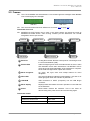
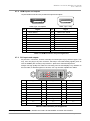
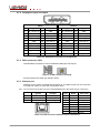
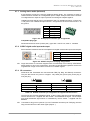
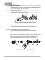
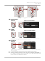
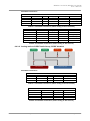
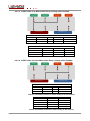
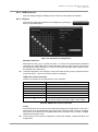
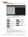
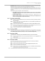
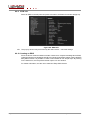
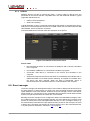
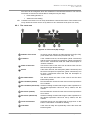
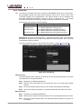
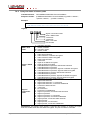
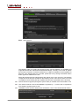
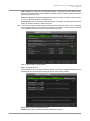
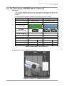
MODEX-F15-OPTS, MODEX-F15-OPTM
User’s Manual
6.6. EDID menu
6.6.1. About EDID memory (transmitter)1
EDID memory is non-volatile and consists of four blocks, each for different purposes:

Factory preset EDIDs

User-saved EDIDs

Dynamic EDID (EDID of last connected sink on the output port)

Emulated EDIDs (EDID currently emulated on a specific input port)
EDIDs are numbered from 1 in each block. They can be referred as the first letter of the
block name and the number of the desired EDID. This way F02 refers to the second factory
preset EDID.
Dynamic and emulated EDID blocks’ size depends on the A/V modules. EDID memory
structure is the following:

F01..F119 .................................................................. Factory Preset EDIDs

U01..U31 ..................................................... User programmable memories

Dxx .................................................. Last attached monitor’s EDID (output)

Exx ...........................................................................Emulated EDID (input)
Dynamic, factory and user EDIDs can be switched and emulated at the input(s).
Info: Factory EDIDs (Fxx) are factory preprogrammed and cannot be modified. These are the
most commonly used resolutions. The EDID list can be found in section 11.3 on page 117.
Info: MODEX can handle both 128 Byte EDID and 256 Byte extended EDID structures.
Info: Attached monitor’s EDID is stored automatically, until a new monitor is attached to that
particular output. In case of powering the unit off, last attached monitor’s EDID remains in
non-volatile memory even if the monitor is disconnected.
6.6.2. EDID types
Most of the factory preset EDIDs include only one resolution. This is to force the connected
source to give a signal with the needed resolution. However there are Universal EDIDs as
well which allow many resolutions.
Factory EDIDs are divided into groups regarding their type. Some EDIDs support DVI only,
some support HDMI and some are for analog VGA signals. Also there are EDIDs for Dual
Link DVI resolutions.
DVI EDIDs does not support audio. Universal DVI EDID indicates support for many PC
(VESA) resolutions.
HDMI EDIDs support embedded audio. These EDIDs have PCM stereo audio format
enabled. To allow other audio formats like Dolby and DTS, special EDIDs have to be used.
There are three Universal HDMI EDIDs which include the same resolutions but support
different capabilities:
EDID
Universal_HDMI_PCM
Universal_HDMI_ALL
Universal_HDMI_DC
PCM audio
yes
yes
yes
other audio
no
yes
yes
deep color
no
no
yes
Table 6-10. Universal HDMI EDIDs
Info: Analog EDIDs are for future developments.
Dual Link DVI EDIDs does not support audio. Use only for Dual Link ports.
1
The exact EDID memory size depends on the firmware and the installed A/V modules.
Section 6. Web control – Using the built-in website
Page 51 / 120
6.6.3. Advanced EDID Management
Select the EDID button from the main menu.
Figure 6-7. EDID management
The window contains two panels: left panel contains the EDIDs that can be used as a
source; right panel contains the target places where the EDIDs can be emulated. The list
can be scrolled by mouse wheel or by grabbing the list.
Control buttons
1Save
Executing EDID
emulation/learning
(Transfer button)
Exporting an EDID (save to
a file)
Load
Importing an EDID (load
from a file)
Clear selected
Deleting EDID (from
user memory)
Info
Opening EDID Summary
window with selected EDID
Select All
Selecting all memory
places in the right
panel
Edit
Opening Advanced EDID
Editor with selected EDID
Unselect All
Selecting none of the
memory places in the
right panel
Create
Opening Easy EDID
Creator
6.6.4. Sources and Destinations
The EDID memory consists of four parts:
Factory EDID list shows the pre-programmed EDIDs (F1-F119).
Dynamic EDID List shows the display device connected to the device's outputs. The unit
stores the last display devices’ EDID on either output, so there is an EDID shown even if
there is no display device attached to the output port at the moment.
User memory shows the memory locations (U1 – U31) which can be used by the user to
save custom EDIDs.
Page 52 / 120
Section 6. Web control – Using the built-in website
MODEX-F15-OPTS, MODEX-F15-OPTM
User’s Manual
Emulated EDID list shows the currently emulated EDID for the inputs. The source column
displays the memory location where the current EDID was routed from.
The source reads the EDID from the Emulated EDID memory on the INPUT port. The user
can copy an EDID from any of the User/Factory/Dynamic EDID lists to the user memory
locations.
There are two types of emulation: static and dynamic.
 Static EDID emulation happens, when an EDID from the Factory or User EDID list
is selected. In this case the Emulated EDID will remain the same until the user
emulates another EDID.
 Dynamic EDID emulation can be enabled by selecting Dx… EDID memory. The
attached monitor’s EDID is copied to the input; if a new monitor is attached to the
output, the emulated EDID changes automatically.
6.6.5. Changing emulated EDID
Step 1. Select the desired EDID list from one of the three sources by pressing its button
above left panel.
Step 2. Select an EDID from the left panel that has to be emulated; the EDID will be
highlighted with yellow cursor.
Step 3. Press the Emulated button above right panel; currently emulated EDID is shown.
Step 4. Select the desired port where the EDID has to be emulated (more ports can also
be selected); the EDID will be highlighted with yellow cursor.
Step 5. Press the Transfer button to change emulated EDID.
6.6.6. Learning an EDID
Info: The process is the same like changing the emulated EDID; the only difference is the target
on the right panel: press the ‘User’ button. Thus one or more EDIDs can be copied into
user memory either from factory memory or from a connected sink (Dynamic).
6.6.7. Exporting an EDID
The EDID listed in left panel can be downloaded as a file (*.bin) to the computer.
Step 1. Select the desired EDID from the left panel (the EDID has to be highlighted with
yellow cursor).
Step 2. Press the Save button to download the file to the computer.
6.6.8. Importing an EDID
Previously saved EDID (*.bin file) can be imported into the user memory as follows:
Step 1. Press the User button above left panel.
Step 2. Select a memory slot from the list; it will be highlighted with yellow cursor.
Step 3. Press the Load button below left panel.
Step 4. Browse the file in the opening window then click on Load EDID. Browsed EDID is
imported into the selected User memory slot.
Info: The imported EDID overwrites the selected memory slot even if it is not empty.
Section 6. Web control – Using the built-in website
Page 53 / 120
6.6.9. EDID info
Select an EDID in the left panel and press Info button; the EDID info window will pop up.
Figure 6-8. EDID info
Info: The pop-up window may be blocked by the web browser – check the settings.
6.6.10. Creating an EDID
Since the above mentioned advanced editor needs more complex knowledge about EDID,
Lightware introduced a wizard like interface for fast and easy EDID creation. With Lightware
Easy EDID Creator it is possible to create custom EDIDs in four simple steps. By clicking
on the wizard icon, the Easy EDID Creator opens in a new window.
For further information, see the user’s manual of Easy EDID Creator.
Page 54 / 120
Section 6. Web control – Using the built-in website
MODEX-F15-OPTS, MODEX-F15-OPTM
User’s Manual
6.6.11. Editing an EDID
Select an EDID from left panel and press Edit button to display Advanced EDID editor
window. Modified EDID can be stored in user memory.
Figure 6-9. Advanced EDID Editor
6.6.12. Deleting EDID(s)
The EDID(s) in User memory can be deleted as follows:
Step 1. Click on User button above right panel.
Step 2. Select one or more EDID from the list that are desired to be deleted.
Step 3. Click on Clear selected button to delete selected EDID(s).
6.7. Control menu
6.7.1. Ethernet tab
The Ethernet tab shows the available Ethernet ports. Under the port settings the name of
the port and the Ethernet mode can be set. Front port is the one on the front panel, Link is
the transmitted line to the other extender. Further ports depend on the installed interface
modules. Below picture shows local and link ports and the two installed modules: module
D contains one Ethernet port, module E contains 4 ports.
Section 6. Web control – Using the built-in website
Page 55 / 120
6.7.2. USB tab
MODEX devices are able to extend two USB 1.1 and/or USB 2.0 devices from the
transmitter to the receiver that are compatible and in line with USB HID standard. Typical
supported USB devices are:

USB mouse and keyboard,

Smart Card (reader).
Typical application is when a computer located at the transmitter is controlled at receiver’s
side by the connected keyboard and mouse via USB. Certain touch monitors fulfill the USB
HID standard, which can also be connected.
Connected USB devices and the status are displayed on the panels:
Figure 6-10. USB tab in the Control menu
Device states

Disconnected: No device is connected to the USB port and no device is emulated
to the computer.

Enumerated: USB device is connected and install is in progress.

Connected: USB device is connected to the receiver and emulated on the
computer.

Suspended: Keyboard and mouse functions are emulated by the extender and no
USB enumeration occurs while operator switching. A computer is not aware when
the device has been changed. When the state is Suspended, device is
disconnected from the extender however it is still emulated to the computer.
6.8. Event manager
The Event manager was developed because of user needs to display internal events (such
as signal present or HDCP active) on GPIO ports, and controlling the device with GPIO
inputs instead of front panel buttons. However the Event manager can be used without
GPIO module, too. The function is very comfortable when the device is built under the desk
and the front panel pushbuttons and LEDs are not accessible.
Basically the Event manager can be configured to detect LW3 CHANGE messages, and if
the condition (the given change message) appears, the event will be fired. The device will
perform an action (send out a preprogrammed LW3 SET or CALL message to itself). E.g.
the desired setup is that after the input signal has been present on the VGA port, the level
of GPIO1 pin is changed. The settings can be done via the LDC in the Control/Events tab,
or by LW3 protocol commands, see section 7.8 on page 87.
Page 56 / 120
Section 6. Web control – Using the built-in website
MODEX-F15-OPTS, MODEX-F15-OPTM
User’s Manual
32 events can be configured, which are available in Control/Events submenu. The user can
see all the 32 events here and is able to modify them by two ways:

Event setting Wizard, or

Advanced event setting.
Info: Conditions and actions can be set by both Wizard or Advanced modes. If the condition was
set by wizard the action can be set by wizard or also advanced mode (and vice versa).
6.8.1. The event area
1
2
3
6
7
4
10
5
8
9
11
Figure 6-11. First event (E1) settings
1
Number of the event
32 events can be defined, the label shows their ID (E1-E32).
(This number is the node in the protocol tree, too.)
2
Condition
If the condition was set, the description (white colored text)
and the exact LW3 protocol expression (yellow colored text)
can be seen. If advanced mode was used the description is
“Custom condition”.
3
Name of the event
Text as the name of the event can be stored. Click into the
text box and type desired name.
4
Action
If the action was set, the description (white colored text) and
the exact LW3 protocol expression (yellow colored text) can
be seen. If advanced mode was used the description is
“Custom action”.
5
Set name button
The device stores the name of the event if the Set name
button was pressed.
6
Set condition (wizard)
Run the wizard to choose from the most common expressions
as a condition.
7
Set condition (advanced) Advanced setting contains wide range of LW3 expressions. If
the desired expression cannot be set by wizard, use this
method.
8
Set action (wizard)
Run the wizard to choose from the most common expressions
as an action.
9
Set action (advanced)
Advanced setting contains wide range of LW3 expressions. If
the desired expression cannot be set by wizard, use this
method.
10 Clear event button
Unwanted events can be cleared with a single click on this
button. Confirmation is needed for deleting.
11 Check bar
If the event is ready and syntactically correct the check bar
becomes green.
Section 6. Web control – Using the built-in website
Page 57 / 120
6.8.2. Wizard mode
A simple wizard makes things easy for the user, because it lists the most common
conditions and actions, so the user does not have to look for LW3 nodes and properties,
the wizard does it instead. Conditions and actions also have their own button.
Step 1. Click on the Wizard button.
Step 2. Select the desired category from the drop-down menu.
All the values can be changed during the whole process.
Step 3. Select an Expression.
The given expressions determine the further possible parameters. E.g. if the Expression is
a video signal detection of any port on the Video layer, the port has to be defined in the
following step.
If the parameters are selected in the drop-down boxes, click on the OK to finish the wizard
of the condition; the set condition can be seen above the buttons. The white text is the
name of the selected condition. The yellow one is the accurate property name and value
by LW3 protocol. You do not need to remember or note this text, LDC shows it continuously.
Page 58 / 120
Section 6. Web control – Using the built-in website
MODEX-F15-OPTS, MODEX-F15-OPTM
User’s Manual
The action is the “reply” if the condition becomes true. There is no sequence between the
condition and the action. Either of them can be set firstly.
Step 4. To set the action, click on the wizard button on the action side.
The process is the same. Click on the down arrow of the drop-down menu than select the
desired item. The category and the expression can be set. If the expression requires further
parameter, select it. E.g. if the Expression is a switching on the video layer, the input and
the output port has to be selected in the next step.
Step 5. Click on the OK to finish the wizard of the action.
The window of the wizard is closed; the created action can be seen above the buttons. The
white text is the name of the selected action, the yellow is the accurate property (and its
value) or method name by LW3 protocol. You do not need to remember or note this text,
LDC shows it continuously. The system checks the validity of the event. If everything is
correct, a green line can be seen at the bottom of the event area.
6.8.3. Advanced mode
The goal of this mode is the same as of the wizard: set the properties and methods for
conditions and actions. The difference is the number of the available and usable properties
and methods of the LW3 protocol. Advanced mode allows almost all of it.
Step 1. Click the Advanced button. A new window comes up.
Step 2. Select the desired node and the property; on the left side there is the closed LW3
tree of the device. To open it, click on the plus sign (in the red square).
Section 6. Web control – Using the built-in website
Page 59 / 120
The tree structure is opened and the available properties are listed in the drop-down box.
The manual of the selected property can be seen below it.
Step 3. Set the desired value in the field next to the list.
Step 4. Click on the OK button to apply the settings.
If the condition is finished, set the action with the same method. The system checks the
validity of the event. If everything is correct, a green line can be seen at the bottom of the
event area.
6.8.4. Save, load or clear an event
Save an event
Although the device stores the set events, – even after reboot or firmware
upgrade – in some cases event saving to the computer can be useful Export to CSV
(e.g. transfer to another MODEX). Events can be stored in a readable
CSV file (Comma Separated Values) which is a human readable file type and can be
imported/edited by many spreadsheet application.
Info: Events cannot be exported one by one. All events will be stored with the exportation.
To save all events click on Export to CSV button, browse the desired folder, then click on
Save button.
Load an event
Click on the Import from CSV button. A browse window comes up.
Find the .CSV file than click on the Open button.
Import from CSV
Clear an event
Click on the Clear button, a confirmation window comes up. Click on the
OK button to clear the event. Clearing the events means setting them to
the factory default values. The names become Event1..32, the condition
and the action get empty value.
Page 60 / 120
Clear
Section 6. Web control – Using the built-in website
MODEX-F15-OPTS, MODEX-F15-OPTM
User’s Manual
Clear all events
All events can be cleared at the same time with the loading
Load factory defaults
factory default values. All the values will be cleared: names,
conditions, actions. Click on the Load factory defaults button. A
warning message appears; confirm it by clicking on the OK button.
6.9. Settings menu
Reboot
When Settings menu is selected, Reboot button is displayed in the right top corner; the
extender can be rebooted after confirmation.
6.9.1. Core tab
The submenu displays information about MODEX frame. Device label can be also changed
which is visible on the front panel LCD.
Figure 6-12. Core tab
6.9.2. Network tab
When the extender is connected to a network or directly to a computer, the necessary
settings can be set in this submenu. If a fixed IP address is planned to use, fill Static IP
address, Static subnet mask and Static gateway fields. If dynamic IP address is planned to
use, set DHCP to Enabled from the drop-down list; other settings are made automatically.
Figure 6-13. Network tab
Click on Apply changes button to save settings.
Section 6. Web control – Using the built-in website
Page 61 / 120
6.9.3. Status tab
Besides some general information and firmware versions in left panel, name of the installed
modules are listed in the right panel of this submenu. System time means the elapsed time
since last boot.
Figure 6-14. Status tab
Cooling of the MODEX
High temp operation
The internal temperature of the MODEX is measured continuously. To protect the internal
parts of the MODEX, there is a feature on the Status tab: High temp operation option.
The unit can be set to respond if the internal temperature is above 80°C:
 Force operation (at your own risk!),
 Restart device (a minute later), or
 Shutdown the device.
Ventilation
MODEX units with hardware v3.0 contain a fan. For older devices a special cooling module
(with a fan) can be installed – optionally. The fan speed is measured and displayed on the
Settings/Status tab, but the fan control is not available on this tab. However, the fan control
can be set via the Advanced view manually at your own risk, the Auto setting (default) is
highly recommended. The Auto mode ensures the necesssary air flow at the lowest
possible fan noise.
Info: The user is not allowed to select „Force operation” setting (High temp operation option)
and limit the fan manually at the same time.
6.9.4. System log tab
Info: The feature is available only when connecting to the MODEX directly (as a Local Device).
The submenu shows events that have been logged by MODEX. Use the selectors to
display the logged Notices, Warnings, Errors or Fatal errors.
 Log button: all events can be saved as a CSV file (Comma Separated Values).
 Error dump: the log file can be saved as a binary file (this is for troubleshooting).
Page 62 / 120
Section 6. Web control – Using the built-in website
MODEX-F15-OPTS, MODEX-F15-OPTM
User’s Manual
Figure 6-15. System log tab
6.9.5. Lock tab
Locking a module means settings of the module cannot
be changed: neither on user interface, nor by protocol
commands (Advanced view); however it will be still
active. Modules and settings can be locked on this page:

Lock core module: Crosspoint change is not
allowed on any layer (Video, Audio, Infra, Serial,
etc…).

Lock LCD Home Screen: When this option is
checked, front panel menu is locked. Only idle
state is shown, front panel operations are
disabled.

Disable setup from LCD menu: Front panel
menu is available, but settings cannot be
changed.
Section 6. Web control – Using the built-in website
Page 63 / 120
6.9.6. Presets tab
Info: The feature is available only when connecting to the MODEX directly (as a Local Device).
Each MODEX extender has eight preset memories which can be used to store LW3
commands (settings and configurations). This feature allows to set the MODEX with
previously determined parameters, execute a group of commands, etc… The preset
memories can be filled by browsing a simple text file that contains the commands.
The structure of the file has to be the following:
Format
;●<description>CrLf
<command1>CrLf
<command2>CrLf
…
<commandn> CrLf
Example
; P1 switching
CALL /MEDIA/VIDEO/XP1:switch(P1:P2)
CALL /MEDIA/VIDEO/XP1:unmuteSource(P1;)
CALL /MEDIA/AUDIO/XP1:switch(P4:P3;P6:P8)
CALL /MEDIA/AUDIO/XP1:unmuteSource(P4;P6;)
● = space character; CrLf = Carriage Return, Line feed
Explanation: The first line must start with “;” (semicolon) character, then a space and the
description of the preset. Lines must be closed with CrLf even the last line, too, or else that
command will not be processed.
The LW3 commands must be in line with the rules written in chapter 7 from page 70.
Figure 6-16. Presets tab
Import a preset
The import allows to store a group of commands in one of the preset memories. The import
is processed from a text file as follows:
Step 1. Navigate to the Settings/Presets tab.
Step 2. Select a slot for the import from the drop-down menu on the left (Import Preset
section).
Step 3. Click on the Browse button below the slot number and select the desired file.
Step 4. Click on the Import preset button. The preset is filled with the content of the file.
Export a preset
Step 1. Navigate to the Settings/Presets tab.
Step 2. Select a slot to export from the drop-down menu on the left (Export Preset section).
Step 3. Click on the Export preset button; the selected preset will loaded to a new tab in
the browser.
Page 64 / 120
Section 6. Web control – Using the built-in website
MODEX-F15-OPTS, MODEX-F15-OPTM
User’s Manual
Apply a preset (run a preset)
Step 1. Navigate to the Settings/Presets tab.
Step 2. Select a preset from the drop-down menu (Apply Preset section). Preset description
is loaded into the textbox and the number of the found commands is displayed, too.
Step 3. Click on the Apply selected preset button; the process indicator shows the status.
The Apply process summary section contains the results:

The number of successfully run commands,

The number of failed commands which could not run, and

The errors during the apply process.
Example
; P1
CALL
CALL
CALL
CALL
switching
/MEDIA/VIDEO/XP1:switch(P1:P2)
/MEDIA/VIDEO/XP1:unmuteSource(P1;)
/MEDIA/AUDIO/XP1:switch(P4:P3;P6:P8)
/MEDIA/AUDIO/XP1:unmuteSource(0;P6;)
After applying (processing) above preset, the result is the following:

Commands in preset:
4

Successful commands:
3

Failed commands:
1

Errors during the apply process: mE /%E001:Syntax error/r/n (line 4)
Explanation: The last command could not be run due to a syntax error. The correct syntax
of the “unmuteSource” method can be found in section 7.4.4 on page 83.
Section 6. Web control – Using the built-in website
Page 65 / 120
6.10. Configuration cloning (Backup tab)
The configuration cloning of Lightware LW3 devices is a simple method that eliminates the
need to repeatedly configure certain devices to have identical (non-factory) settings. If the
devices are installed in the same type of system multiple times then it is enough to set up
only one device to fit the user’s needs and then copy those settings to the others, thus
saving time and resources.
Info: The feature is available only when connecting to the MODEX directly (as a Local Device).
6.10.1. Cloning steps in a nutshell
Installing multiple devices with the same customized configuration settings can be done in
a few easy steps:
Step 1. Configure one device with all your desired settings with the LDC software.
Step 2. Backup the full configuration file to your computer.
Step 3. If needed, make some modifications to the configuration file using a text editor (e.g.
Notepad). For example modifying the static IP address is needed when DHCP is
not used.
Step 4. Connect to the other device which has to be configured and upload (restore) your
configuration file.
Step 5. Ready! You can have as many totally identical, customized devices as you like.
6.10.2. Save the settings of the extender (Backup)
Step 1. Apply the desired settings in the extender (port parameters, crosspoint, system
settings.)
Step 2. Select the Settings / Backup tab from the menu.
Step 3. Write a short description in the textbox on the left (optional).
Step 4. Press the Create a full backup button. You will be prompted to save the file to the
computer. The default file name is the following:
BACKUP_<DEVICE LABEL>_SN<SERIAL NUMBER>.LW3
e.g.
backup_MEX-108-228-410-715-721_SN5A001192.lw3
Step 5. Set the desired file name, select the folder and save the file.
Info: Using the exact product type in the filename is recommended since it makes the file usage
more comfortable.
About the backup file
The backup file is a simple text file which contains LW3 protocol commands. The first line
is the description, and the further lines are the commands which will be executed during
the restore process. The file can be viewed (and/or edited) by a simple text editor, e.g.
Notepad. The exact content of the file is listed in section 11.4 on page 118.
Info: Editing the command lines is only recommended for expert users.
Page 66 / 120
Section 6. Web control – Using the built-in website
MODEX-F15-OPTS, MODEX-F15-OPTM
User’s Manual
6.10.3. Upload the settings to a device (Restore)
Warning! Please note that the settings will be permanently overwritten with the restored parameters
in the device. Withdrawal is not possible.
Info: The cloning is successful when the backup file is downloaded from the same type of source
device as the destination device. E.g. if a MODEX contains a group of modules and the
backup file is uploaded to another MODEX – which contains different modules – that would
result in errors when checking and uploading.
The restoring process
Step 1. Select the Settings / Backup tab from the menu.
Step 2. Click on the Browse button on the right panel and select the desired file.
Step 3. The file is checked and the result will be displayed in the textbox below. If the file is
correct, the settings can be restored.
Step 4. Press the Start restore process button and click on the Yes button when asked.
Step 5. Reboot the device to apply the network settings after finishing.
6.10.4. Network settings
The backup file contains some lines with the network settings:
Above example shows that line nr. 202 contains that the DHCP is disabled and line nr. 205
contains the static IP address of the appliance. If the file is uploaded to one or more devices,
the exact same settings will be applied. To avoid a possible IP address conflict on the
network, follow one of these steps:
Option 1 – Use the DHCP in all the devices
 Before the backup process: Make sure that the DHCP is enabled in the device, or
 After the backup process: Modify the backup file in a text editor (e.g. Notepad) and
search the following line:
SET /MANAGEMENT/NETWORK.DhcpEnabled=false
Replace the false value to true.
Info: The static IP address will be uploaded to the device if the line is in the backup file but will
be ignored when DHCP is enabled.
Info: The factory default IP address of the LW3 devices is static.
Option 2 – Use fix IP addresses
Be aware that if the backup file is uploaded (restored) in multiple devices, it will cause an
IP address conflict. In this case you have to change the IP address in the backup file
manually before uploading it to each device; search this line:
SET /MANAGEMENT/NETWORK.StaticIpAddress=192.168.0.80
Set the DHCP setting to false, set the desired IP address and save the file.
Option 3 – Keep the original IP settings
If the Network settings of the destination device shall stay unchanged, make sure that these
lines are deleted from the backup file, before you upload and restore it in a device. The
network settings are listed at the end of the file (the lines starting with
SET /MANAGEMENT/NETWORK and CALL /MANAGEMENT/NETWORK).
Section 6. Web control – Using the built-in website
Page 67 / 120
6.11. Advanced view
Advanced view is the surface for LW3 protocol settings with a terminal window. Commands
and specific parameters (that are not available on the user interface) can be run and set.
Detailed information about the protocol, nodes, methods and parameters can be found in
chapter 7 on page 70. Click on Close button to hide the Advanced view.
3
4
1
2
Figure 6-17. Advanced view
1
Terminal window
Commands and responses are listed in this window. The
timecode in every row shows the exact time when the command
was sent or the response received. Sent command is displayed
in red and starts with ‘>’ character, received response is
displayed in blue and starts with ‘<’ character. The content of the
window can be emptied by the Clear button.
2
Controls
Commands/queries can be typed directly in the textbox.
3
Page 68 / 120
Protocol tree
Send button:
Execute the command in the field.
Clear button:
Empty the terminal window.
Autoscroll:
The terminal window is scrolled
automatically when a new line
appears. Untick the option to freeze
the window.
Open terminal window:
The separate window can show the
commands and responses after
closing the advanced view.
Enable editing:
When the Advanced view is opened,
the values in the boxes cannot be
modified (displayed in dark grey). To
unlock the boxes untick this option.
Displays the LW3 node tree.
Section 6. Web control – Using the built-in website
MODEX-F15-OPTS, MODEX-F15-OPTM
User’s Manual
4
Node content
The properties and methods are shown which belong to the
selected node in the protocol tree.
Manual button:
Manual (short description) of the node can be
called and displayed in the terminal window.
See more information about manuals in
section 7.2.9 on page 79.
Set button:
Saves the value/parameter typed in the
textbox.
Call button:
Calls the method with the typed value, e.g.
reloads factory default settings.
Info: If a module is locked, its settings cannot be changed; parameters, values will not be saved,
and factory default settings cannot be reloaded.
Section 6. Web control – Using the built-in website
Page 69 / 120
7. Programmer’s reference
7.1. LW3 protocol – Overview
Lightware 3 (LW3) protocol is currently used by MODEX extender family, 25G product line
and will be the preferred protocol in new developments.
LW3 is an ASCII based protocol and all commands are terminated with a carriage return
(Cr, ‘\r’) and line feed (Lf, ‘\n’) pair. It is organized as a tree structure that provides
outstanding flexibility for implementing a human readable, but still easy to programmatically
parse protocol, which is suitable for different products with different feature list.
The concept
In order to implement a flexible, easy-to-use protocol that is straightforward to adapt to new
devices and provides outstanding scalability and sustainability, Lightware decided to
organize all settings, parameters and properties of the device to a tree structure with
‘nodes’, ‘properties’ and ‘methods’.
7.1.1. Elements of tree structure
Info: All names and values are case sensitive. The space character is replaced by ‘●’ character
in elements and commands descriptions.
Node
 The basic building block of the tree structure is the ‘node’.
 A node can have multiple child nodes, but only one parent.
 The tree has only one root the ‘root node’.
 The leaves of the tree are also nodes, which do not have child nodes.
 The nodes are separated by a slash (‘/’) character.
 All the slashes are ‘right slashes’, no backslash is used.
 The identifier of the root node it a slash (‘/’)
 Nodes’ name can contain the elements of the English alphabet and numbers.
 Recommended convention for case sensitivity:
-
Fix nodes (that cannot be altered) are capitalized.
- User created nodes can contain both lowercase and capital letters, no
restrictions.
 The path of a node has to contain all parent nodes from the root node.
Format (the root node): nX●/
Path: nX●/[nodeName]/[nodeName]/[nodeName]
Legend:
‘n’:
node
‘X’ can be:
‘-’:
default for a node,
‘m’:
manual for the node (see section 7.2.9 on page 79),
‘E’:
error message for the node (see section 7.1.3 on page 73),
's'
this is a symlink node
Info: All parent nodes must be listed in the path of a node.
Page 70 / 120
Section 7. Programmer’s reference
MODEX-F15-OPTS, MODEX-F15-OPTM
User’s Manual
Following example presents the depth tree traversal of Figure 7-1:
n-/
Path of the nodes:
node1
n-/node1
node11
n-/node1/node11
node12
n-/node1/node12
node2
n-/node2
n-/node2/node21
node21
node211
n-/node2/node21/node211
n-/node3
node3
Figure 7-1. Tree structure of nodes
Property
The ‘property’ in the LW3 protocol is basically a leaf, which has a well-defined value.
 A property has a value.
 A property cannot have child nodes or child properties. It is always a leaf.
 A node can have any number of properties (may not have any).
 A property is referenced with a dot (‘.’) after the node name.
 The properties’ name can contain the elements of the English alphabet, numbers
and underscore (‘_’) character.
 By convention, properties are beginning with capital letter, all other characters are
lowercase ones. In case of compound words, all words are beginning with a capital
letter (CamelCase).
 The value of the property can contain any readable ASCII character (the control
characters have to be escaped, see section 7.1.2 on page 72).
 A property can be read-only or read/write.
Format: pX●/[nodeName].[propertyName]=[propertyValue]
Legend:
p:
property
X can be:
‘r’:
if the property is read-only.
‘w’:
if the property is readable, writable.
‘m’:
manual for the property (see section 7.2.9 on page 79).
‘E’:
error message for the property (see section 7.1.3 on page 73).
Example:
First one is a read-only property, second one is a read-write property:
< pr●/SYS/CORE.PartNumber=91610103
< pw●/SYS/CORE.DeviceLabel=MODEX-F15-OPTS
Section 7. Programmer’s reference
Page 71 / 120
Method
‘Method’ in the LW3 protocol is also a leaf. It cannot have a value, such as the properties,
but it can be invoked with a parameter with the help of a special ‘CALL’ command (see
section 7.2.5 on page 76).

A method cannot have child nodes or child methods. It is always a leaf.

A node can have any number of methods (may not have any).

A method is referenced with a colon (‘:’) after the node.

Methods’ name can contain the elements of the English alphabet, numbers and
underscore (‘_’) character.

By convention, methods are beginning with lowercase letter. In case of compound
words, the very first letter is lowercase, and the first letter of each other words are
capitalized (lowerCamelCase).

The parameter of the method can contain any readable ASCII character (control
characters have to be escaped, see section 7.1.2 on page 72).

The method always has a return ‘state’ if the method could be executed. The state
could be either ‘OK’ or ‘FAILED’.

The method not necessarily has a return ‘value’. If it does, it can contain additional
information, which is always specific for the current case (return value can specify
why the execution failed). Find details in section 7.2.5 on page 76.

When the method cannot be executed (e.g. the parameter list is illegal), there is
an error message (see section 7.1.3 on page 73).
Format: mX●/[nodeName]:[methodName]=[returnValue]
Legend:
m:
method
X can be:
‘O’:
when the execution of the method was successful,
‘F’:
when the execution of the method failed,
‘m’:
manual for the method (see section 7.2.9 on page 79),
‘E’:
error message for the method (see section 7.1.3 on page 73).
Example:
< mO●/node1/node12:method1
< mO●/MEDIA/IR/XP1:DefaultSwitch
< mO●/EDID:DeleteEdid
7.1.2. Escaping
Property values and method parameters can contain characters that are used as control
characters in the protocol. They must be escaped. The escape character is the backslash
(‘\’) and escaping means injecting a backslash before the character that should be escaped
(like in C language).
Control characters are the followings: \ { } # % ( ) \r \n \t
Example:
Page 72 / 120
Original text:
John●(Doe).●#3:●5%2=1●node1\node11
Escaped text:
John●\(Doe\).●\#3:●5\%2=1●node1\\node11
Section 7. Programmer’s reference
MODEX-F15-OPTS, MODEX-F15-OPTM
User’s Manual
7.1.3. Error messages
There are several error messages defined in LW3 protocol. All of them have a unique error
number which can be used programmatically, and an informative error message.
Format: XE●[primitive]●%EYYYY:●[Error message]
Legend:
X can be:
‘-’:
syntax error. Cannot parse the command at all.
‘n’:
node error.
‘p’:
property error.
‘m’:
method error.
YYY: error code, which can be one of the followings:
YYY: error code
Name
Default text
000
Lw3ErrorCodes_None
001
Lw3ErrorCodes_Syntax
Syntax error
002
Lw3ErrorCodes_NotFound
Not found
003
Lw3ErrorCodes_AlreadyExists
Already exists
004
Lw3ErrorCodes_InvalidValue
Invalid value
005
Lw3ErrorCodes_IllegalParamCount
Illegal parameter count
006
Lw3ErrorCodes_IllegalOperation
Illegal operation
007
Lw3ErrorCodes_AccessDenied
Access denied
008
Lw3ErrorCodes_Timeout
Timeout
009
Lw3ErrorCodes_CommandTooLong
Command too long
010
Lw3ErrorCodes_InternalError
Internal error
011
Lw3ErrorCodes_NotImplemented
Not implemented
7.1.4. Prefix summary
The following prefixes are defined in LW3 protocol:
‘n-’:
a node,
‘nE’: an error for a node,
‘nm’: a manual for a node,
'ns':
a symlink node (the node is a copy of another node from the node tree)
‘pr’:
a read-only property,
‘pw’: read-write property,
‘pE’: an error for the property,
‘pm’: a manual for the property,
‘m-’: a method,
‘mO’: a response after a success method execution,
‘mF’: a response after a failed method execution,
‘mE’: an error for a method,
‘mm’: a manual for a method.
Symlink: Instead of inserting the same node twice to the node tree, we can add symlinks.
The user will be able to access the functions of the node from two or more paths.
Section 7. Programmer’s reference
Page 73 / 120
7.2. Commands
Getter
The ‘GET’ command can be used to get sub nodes, properties and methods of a specific
node. It also can be used to get the value of a property.
Response format
The first two characters of a response are unambiguously identifies the type of the element
that the response line concerns. First character is the type of the element
(node/property/method), second is for miscellaneous information (e.g. read/write rights).
The defined prefixes
‘n-’:
node
‘pr’:
property – only readable
‘pw’: property – writable, readable
‘m-’: method executable
After prefix the response contains the full path of the node, property or method after a space
character.
7.2.1. Get all children of a node
Get all of the child nodes of a parent node, with one GET command.
Command format: GET●[nodePath]
Response format: n-●[nodePath]
Example:
>
<
<
<
GET●/MEDIA/IR
n-●/MEDIA/IR/XP1
n-●/MEDIA/IR/P1
n-●/MEDIA/IR/P2
7.2.2. Get all properties and methods of a node
Get all properties and methods of a specific node, with one GET command, using an
asterisk wildchar.
Command format: GET●[nodePath].*
Response format: (for properties)
pX●[nodePath].[propertyName]=[parameter]
Legend:
X can be:
‘r’:
read-only
‘w’:
read-write
Response format: (for methods)
m-●[nodePath]:[methodName]
Example:
>
<
<
<
Page 74 / 120
GET●/PRESETS/1.*
pr●/PRESETS/1.Index=1
pw●/PRESETS/1.RemoveLock=false
pw●/PRESETS/1.Text=Preset 1
Section 7. Programmer’s reference
MODEX-F15-OPTS, MODEX-F15-OPTM
User’s Manual
7.2.3. Get all child nodes, properties and methods of a node
Get all child nodes, properties and methods of a node with one command, without using a
wildchar.
Command format: GETALL●[nodePath]
Response format: (for nodes)
n-●[nodePath]
Response format: (for properties)
pX●[nodePath].[propertyName]=[parameter]
Legend:
X can be:
‘r’:
read-only
‘w’:
read-write
Response format: (for methods)
m-●[nodePath]:[methodName]
Example:
>
<
<
<
<
<
<
<
<
GETALL●/MANAGEMENT
n-●/MANAGEMENT/NETWORK
n-●/MANAGEMENT/STATUS
n-●/MANAGEMENT/LOCK
n-●/MANAGEMENT/LOG
pr●/MANAGEMENT.rebootNeeded=false
pw●/MANAGEMENT.WebEnvironment=
m-●/MANAGEMENT:Udc
m-●/MANAGEMENT:Msg
Info: The command does not list child nodes and properties of listed child nodes, only that
belongs to the node directly. E.g. the child nodes and properties of
/MANAGEMENT/NETWORK is not listed in this example, those can be queried if
‘GETALL●/MANAGEMENT/NETWORK’ is run.
7.2.4. Set command
The setter command can be used to modify the value of a property.
Command format: SET●[nodePath].[propertyName]=[newPropertyValue]
Response format:
The response for setting a property to a new value is the same as the response for ‘GET’
command. The value in the response is the new value if the execution of ‘SET’ command
was successful, otherwise the unmodified ‘old value’ with an error message.
pw●[nodePath].[propertyName]=[newPropertyValue]
Example:
> SET●/MANAGEMENT/NETWORK.PortNumber=6107
< pw●/MANAGEMENT/NETWORK.PortNumber=6107
Error response format:
If there were errors during setting a property, an error message follows the unmodified
property value. Find the error numbers in section 7.1.3 on page 73.
pE●[nodePath].[propertyName]=[umodifiedValue]●%EXXX:Error message
Legend:
XXX: error number (see section 7.1.3 on page 73).
Section 7. Programmer’s reference
Page 75 / 120
Examples:
>
<
>
<
>
<
>
<
SET●/SYS/CORE/B/VIDEODVOOO.HdcpEnable=false
nE●%E002:Node not found
SET●/SYS/CORE.PartNumber=12345678
pE●%E004:Writing read-only property
SET●/SYS/CORE/B/VIDEODVI.HdcpEnable=falssss
pE●%E005:Invalid value
SET●/SYS/CORE/B/VIDEODVI.HdcpEnab=false
pE●%E006:Property not exists
7.2.5. Invocation
A method can be invoked with the help of ‘CALL’ command.
Command format: CALL●[nodePath]:[methodName]([parameter])
Response format:
The response for a method execution is a state and a value. The state is mandatory and
always defined, if the method could be executed. It can be either a success or a failure.
The value is optional and it can contain additional information – such as the reason why
the state is a failure or a specific value when the state is success – which the client can
process. It is also possible to get an error message, when the method could not be
executed – e.g. the parameter was illegal – and hence not even the state of the execution
could be specified.
mX●[nodePath]:[methodName]=Y
Legend:
X can be:
‘O’:
if the execution is successful.
‘F’:
if the execution is failed, but the method could be executed.
‘E’:
if the method could not be executed: e.g. illegal parameter count.
‘Y’ can be:

the return value of the method if any.

it is valid that a method does not have any return value. In this case the
equal sign (‘=‘) can be omitted.
Example:
> CALL●/MANAGEMENT/LOCK:LockAll()
< mO●/MANAGEMENT/LOCK:LockAll
Error response format:
If there were errors during the execution, an error message is received, which follows the
method name. Find the error codes in section 7.1.3 on page 73.
mE●[nodePath]:[methodName]●%EXXX:Error message
Example:
> CALL●/EDID:DeleteEdid(U100)
< mE●%E005:Invalid●value
7.2.6. Subscription
User can subscribe to any node. Subscribe to a node means that user will get a notification
if any of the properties of the node is changed. These notifications are asynchronous
messages – such as the ones described above – and hence they are useful to keep client
application up-to-date, without receiving any unwanted information. When user does not
want to be informed about the changes anymore, he can simply unsubscribe from the node.
Page 76 / 120
Section 7. Programmer’s reference
MODEX-F15-OPTS, MODEX-F15-OPTM
User’s Manual
Info: The subscriptions are handled separately for connections and not for users. Hence, if the
connection is terminated all registered subscriptions are deleted. After every connection
the subscribe command has to be sent in order to get the notifications of the changes.
Subscribe to a node
Command format: OPEN●[nodePath]
Response format: o-●[nodePath]
Example:
> OPEN●/MANAGEMENT/NETWORK
< o-●/MANAGEMENT/NETWORK
Subscribe to multiple nodes
In order to subscribe to multiple nodes, asterisk wildchar can be used.
Command format: OPEN●[nodePath]/*
Response format: o-●[nodePath]/*
Example:
> OPEN●/MANAGEMENT/LOG/*
< o-●/MANAGEMENT/LOG/*
Get the active subscriptions
Issuing an ‘OPEN’ command without any parameters returns the active subscriptions for
the current connection.
Command format: OPEN
Response format: o-●[nodePath]
Example:
>
<
<
<
<
<
OPEN
o-●/SYS/CORE
o-●/MEDIA/VIDEO
o-●/MEDIA/AUDIO
o-●/MEDIA/IR
o-●/MEDIA/UART
Unsubscribe from a node
Command format: CLOSE●[nodePath]
Response format: c-●[nodePath]
Example:
> CLOSE●/MANAGEMENT/LOCK
< c-●/MANAGEMENT/LOCK
Unsubscribe from multiple nodes
In order to subscribe to multiple nodes, asterisk wildchar can be used.
Command format: CLOSE●[nodePath]/*
Response format: c-●[nodePath]/*
Example:
> CLOSE●/MANAGEMENT/*
< c-●/MANAGEMENT/*
Section 7. Programmer’s reference
Page 77 / 120
7.2.7. Notifications about the changes of the properties
When the value of a property is changed and the user is subscribed to the node, which the
property belongs to, an asynchronous notification is generated. This notification is called
as the ‘change message’. The format of such a message is very similar to the response for
‘GET’ command.
Format: CHG●[nodePath].[propertyName]=[newPropertyValue]
A short example of how to use the subscription
Below an example is presented, how the subscriptions work and how to use them. In the
example there are two independent users controlling the device through two independent
connections (‘C #1’ and ‘C #2’). The events in the rows occur after each other.
> OPEN●/EDID
< o-●/EDID
C #1
> GET●/EDID.EdidStatus
< pr●/EDID.EdidStatus=D1:E1;D1:E2
- User1 subscribes to /EDID node
> GET●/EDID.EdidStatus
< pr●/EDID.EdidStatus=D1:E1;D1:E2
C #2
> CALL●/EDID:switch(U1:E1)
< mO●/EDID:switch
- User2 queries /EDID.EdidStatus
> CHG●/EDID.EdidStatus=U1:E1;D1:E2
C #1 > CLOSE●/EDID
< c-●/EDID
- User1 got a change message
- User1 unsubscribes from the node
- User1 queries /EDID.EdidStatus
- User2 switches EDID
7.2.8. Signature
For some command the response can contain multiple lines. Every line is terminated with
a carriage return (Cr, ‘\r’) and line feed (Lf, ‘\n’) characters. In several cases the number of
the lines in the response cannot be determined in advance. In several cases the client is
intended waiting for the whole response and also wants to be sure, that received lines
belong together and to the same command. In these cases a special feature the ‘signature’
can be used.
The signature is a four-digit-long hexadecimal value that can be optionally placed before
every command. In that case, the response to that particular command will also be
preceded by the signature, and the corresponding lines will be in between brackets.
Command format: XXXX#[command]
Legend:
xxxx: four-digit-long hexadecimal value.
Response format:
{XXXX
[command lines]
}
Example:
>
<
<
<
<
<
<
<
0001#GET●/MEDIA
{0001
n-●/MEDIA/VIDEO
n-●/MEDIA/AUDIO
n-●/MEDIA/UART
n-●/MEDIA/IR
n-●/MEDIA/PACKETROUTER
}
Info: The lines of the signature are also Cr and Lf terminated.
Page 78 / 120
Section 7. Programmer’s reference
MODEX-F15-OPTS, MODEX-F15-OPTM
User’s Manual
7.2.9. Manual
For every property and method in the tree there is a manual. The manual is a human
readable text that describes the syntax and provides a hint for how to use the primitives.
Command format:
for property:
MAN●[nodePath].[propertyName]
for method:
MAN●[nodePath]:[methodName]
Response format:
The human readable manual is separated by a space (‘ ‘) character from the primitives.
for properties: pm●[nodePath].[propertyName]●Human readable manual
for methods:
mm●[nodePath]:[methodName]●Human readable manual
Example:
>
<
>
<
MAN●/PRESETS.Count
pm●/PRESETS.Count:[int] Number of presets
MAN●/SYS/CORE:ResetLink
mm●/SYS/CORE:ResetLink:Reset optical link.
7.2.10. Formal definitions
Method parameters and property values are specified in a modified version of Backus-Naur
Form (BNF). The syntax is the following:
“literal”
<expression1> | <expression2>
[ <expression> ]
literals are quoted
vertical bars denote alternatives
expressions in square brackets are optional
<number>*[ <expression> ]
expression is repeated at least <number>
times
*[ <expression> ]
<number> may be omitted, in this case number
defaults to 0
<number>*{ <expression> }
expressions in curly brackets are repeated
exactly <number> times
7.3. LW3 protocol tree
The /MEDIA node contains the sub nodes which are representing the different layers, e.g.
video (/MEDIA/VIDEO), audio (/MEDIA/AUDIO) or RS-232 (/MEDIA/UART). Each layer
has a crosspoint to define connections between the ports associated to the layer, all of
them are represented by a specific node. E.g. the video layer node is /MEDIA/VIDEO:
under the video layer node, the video crosspoint node (XP1) and the video ports
(P1, P2, …) are located.
Section 7. Programmer’s reference
Page 79 / 120
The exact content of the nodes (especially the /MEDIA node) depend on the installed
modules. The tree structure is available via the Web (Advanced view), see section 6.11 on
page 68.
7.3.1. /REMOTE
The node contains the protocol tree of the remote device (if connected): PRESETS,
MANAGEMENT, EDID, MEDIA, SYS and EVENT sub nodes. Settings and values are valid
for the remote device only below the /REMOTE node.
7.3.2. /PRESETS
Group node for the eight available presets; each preset has own sub node with its
properties.
7.3.3. /MANAGEMENT/
A group node for every management related settings. The features and settings here are
not related to the current crosspoint settings. The node contains the following sub nodes:
/MANAGEMENT/NETWORK
Contains Network-related properties, such as IP address, Gateway, Subnet mask, DHCP
and Port settings.
/MANAGEMENT/STATUS
Basic status values are stored about the MODEX: Firmware versions, Internal Voltage
values, Module code, System time (elapsed time since last booting in seconds).
/MANAGEMENT/LOCK
Installed modules can be locked/unlocked individually or together.
Info: The locking state is also stored under /SYS/CORE nodes and its sub nodes (as read-only
property), but the settings can be done in /MANAGEMENT/LOCK.
/MANAGEMENT/LOG
Last logged events can be queried here. /MANAGEMENT/LOG node contains five
properties (Warning, Error, Debug, Fatal and Notice), which shows the number of the
occurrence of the given event type. The log can be emptied by the calling the clearLog
method.
The node has five sub nodes (NOTICE, WARNING, ERROR, FATAL, DEBUG) which
contain the log entries as a property describing the logged event with details.
Page 80 / 120
Section 7. Programmer’s reference
MODEX-F15-OPTS, MODEX-F15-OPTM
User’s Manual
7.3.4. /EDID
The node and its sub nodes represent all information about EDID management. The node
contains basic methods in connection with EDID emulation such as Copy, Delete or
Emulate EDID. Sub nodes refer to the type of the EDID as follows:
F:
Factory EDIDs,
U:
User EDID,
D:
Dynamic EDID (The EDID of the monitor last attached to the receiver),
E:
Emulated EDID (List of assigned video ports).
The node structure of Factory, User and Dynamic EDIDs contain the available EDIDs as
sub nodes. The structure of these EDID sub nodes is the same:
Header:
Valid/Invalid (based on EDID header)
Data:
EDID data – in HEX format
IsValid:
True/False – (based on EDID data)
For detailed information about EDID memory see section 6.6.1 on page 51.
7.3.5. /MEDIA
MEDIA node contains the available layers on installed modules, such as VIDEO, AUDIO,
UART or IR module. Port and Crosspoint settings are structured in sub nodes with methods
and properties in the nodes of the layers.
7.3.6. /SYS
The node has two sub nodes: LOG and CORE.
/SYS/LOG
Last log events collected from last booting. The structure is the same as for
/MANAGEMENT/LOG.
/SYS/CORE
The node contains properties of MODEX frame; nevertheless its sub nodes contain the
installed modules (B, C, D and E). Signal parameters are listed in the sub nodes.
7.4. Video port and crosspoint settings
Info: Port numbers, commands and responses depend on the modules built in the given MODEX
unit; see the P1..Pn properties under /MEDIA/VIDEO node.
7.4.1. Query the video crosspoint setting
Command format: GET●/MEDIA/VIDEO/XP1.DestinationConnectionList
Response format: pr●/MEDIA/VIDEO/XP1.DestinationConnectionList=<input>:<output>
Legend:
<input>:
Video input port number
<output>:
Video output port number
Example:
> GET●/MEDIA/VIDEO/XP1.DestinationConnectionList
< pr●/MEDIA/VIDEO/XP1.DestinationConnectionList=P2:P3
Section 7. Programmer’s reference
Page 81 / 120
7.4.2. Query the status of source ports
Command format:
GET●/MEDIA/VIDEO/XP1.SourcePortStatus
Response format:
pr●/MEDIA/VIDEO/XP1.SourcePortStatus=[<port#1>:<status>;
<port#2>:<status>;…;<port#n>:<status>]
Example:
> GET●/MEDIA/VIDEO/XP1.SourcePortStatus
< pr●/MEDIA/VIDEO/XP1.SourcePortStatus=P2:T000B
Legend
P2:T00AF
Signal / Connection state
Audio / HDCP state
<reserved>
<reserved>
Mute / lock state
Port number
Mute / lock
state
Audio / HDCP
state
Signal /
connection
state
T:
L:
M:
U:
0:
1:
2:
3:
4:
5:
6:
7:
8:
9:
A:
B:
C:
D:
E:
F:
0:
1:
2:
3:
4:
5:
6:
7:
8:
9:
A:
B:
C:
D:
E:
F:
unlocked, unmuted
locked, unmuted
unlocked, muted
locked, muted
audio unknown, HDCP state unknown
audio signal unknown
audio unknown, not HDCP-encrypted
audio unknown, HDCP-encrypted
HDCP state unknown
<reserved>
signal is not HDCP-encrypted
signal is HDCP-encrypted
embedded audio not present, HDCP state unknown
embedded audio not present
embedded audio not present, signal is not HDCP-encrypted
embedded audio not present, signal is HDCP-encrypted
embedded audio is present, HDCP state unknown
embedded audio is present
embedded audio is present, signal is not HDCP-encrypted
embedded audio is present, signal is HDCP-encrypted
Signal and connection states unknown
Signal state unknown
Signal state unknown, no connection
Signal state unknown, connection established
Connection state unknown
<reserved>
No connection
Connection is established
Signal not present, connection state unknown
Signal not present
Signal not present, no connection
Signal not present, connection established
Signal present, connection state unknown
Signal present
Signal present, no connection
Signal present, connection established
Explanation: (P2:T00AF) Video signal is connected and present on Port#2, the signal
does not contain audio and not HDCP-encrypted. The port is unlocked, unmuted.
Page 82 / 120
Section 7. Programmer’s reference
MODEX-F15-OPTS, MODEX-F15-OPTM
User’s Manual
7.4.3. Mute an input port
Command format: CALL●/MEDIA/VIDEO/XP1:muteSource(<input>)
Response format: mO●/MEDIA/VIDEO/XP1:muteSource
Legend:
<input>:
Input port number
Example:
> CALL●/MEDIA/VIDEO/XP1:muteSource(P1)
< mO●/MEDIA/VIDEO/XP1:muteSource
7.4.4. Unmute an input port
Command format: CALL●/MEDIA/VIDEO/XP1:unmuteSource(<input>)
Response format: mO●/MEDIA/VIDEO/XP1:unmuteSource
Legend:
<input>:
Input port number
Example:
> CALL●/MEDIA/VIDEO/XP1:unmuteSource(P1)
< mO●/MEDIA/VIDEO/XP1:unmuteSource
7.4.5. Lock an input port
Command format: CALL●/MEDIA/VIDEO/XP1:lockSource(<input>)
Response format: mO●/MEDIA/VIDEO/XP1:lockSource
Legend:
<input>:
Input port number
Example:
> CALL●/MEDIA/VIDEO/XP1:lockSource(P1)
< mO●/MEDIA/VIDEO/XP1:lockSource
7.4.6. Unlock an input port
Command format: CALL●/MEDIA/VIDEO/XP1:unlockSource(<input>)
Response format: mO●/MEDIA/VIDEO/XP1:unlockSource
Legend:
<input>:
Input port number
Example:
> CALL●/MEDIA/VIDEO/XP1:unlockSource(P1)
< mO●/MEDIA/VIDEO/XP1:unlockSource
7.4.7. Mute the output
Command format: CALL●/MEDIA/VIDEO/XP1:muteDestination(<output>)
Response format: mO●/MEDIA/VIDEO/XP1:muteDestination
Legend:
<output>:
Output port number
Example:
> CALL●/MEDIA/VIDEO/XP1:muteDestination(P2)
< mO●/MEDIA/VIDEO/XP1:muteDestination
Section 7. Programmer’s reference
Page 83 / 120
7.4.8. Unmute the output
Command format: CALL●/MEDIA/VIDEO/XP1:unmuteDestination(<output>)
Response format: mO●/MEDIA/VIDEO/XP1:unmuteDestination
Legend:
<output>:
Output port number
Example:
> CALL●/MEDIA/VIDEO/XP1:unmuteDestination(P2)
< mO●/MEDIA/VIDEO/XP1:unmuteDestination
7.4.9. Lock the output
Command format: CALL●/MEDIA/VIDEO/XP1:lockDestination(<output>)
Response format: mO●/MEDIA/VIDEO/XP1:lockDestination
Legend:
<output>:
Output port number
Example:
> CALL●/MEDIA/VIDEO/XP1:lockDestination(P2)
< mO●/MEDIA/VIDEO/XP1:lockDestination
7.4.10. Unlock the output
Command format: CALL●/MEDIA/VIDEO/XP1:unlockDestination(<output>)
Response format: mO●/MEDIA/VIDEO/XP1:unlockDestination
Legend:
<output>:
Output port number
Example:
> CALL●/MEDIA/VIDEO/XP1:unlockDestination(P2)
< mO●/MEDIA/VIDEO/XP1:unlockDestination
7.5. Audio port and crosspoint settings
Info: Port numbers, commands and responses depend on the modules built in the given MODEX
unit; see the P1..Pn properties under /MEDIA/AUDIO node.
There are two audio groups in MODEX extenders: S/PDIF and Main audio groups. This is
also visible in the protocol tree:

/MEDIA/AUDIO/XP1 : node of the audio ports within S/PDIF group

/MEDIA/AUDIO/XP2 : node of the audio ports within Main audio group
Info: The available ports within a group depend on the audio module setting. See more
information in section 6.3.2 on page 40.
7.5.1. Query the audio crosspoint setting
Command format: GET●/MEDIA/AUDIO/XP1.DestinationConnectionList
Response format: pr●/MEDIA/AUDIO/XP1.DestinationConnectionList=<input>:<output>
Legend:
<input>:
Audio input port number
<output>:
Audio output port number
Example:
> GET●/MEDIA/AUDIO/XP1.DestinationConnectionList
< pr●/MEDIA/AUDIO/XP1.DestinationConnectionList=P6:P4;P3:P8
Explanation: P6 input is connected to P4 output, P3 input is connected to P8 output.
Page 84 / 120
Section 7. Programmer’s reference
MODEX-F15-OPTS, MODEX-F15-OPTM
User’s Manual
7.5.2. Switching audio input
Command format: CALL●/MEDIA/AUDIO/XP1:switch(<input>:<output>)
Response format: mO●/MEDIA/AUDIO/XP1:switch
Legend:
<input>:
Audio input port number
<output>:
Audio output port number
Example:
> CALL●/MEDIA/AUDIO/XP1:switch(P3:P4)
< mO●/MEDIA/AUDIO/XP1:switch
Explanation: P3 input port is switched to P4 output port.
Info: The current audio mode determines the possible crosspoint switches.
7.6. RS-232 port configuration
7.6.1. BAUD rate setting
Command format: SET●/MEDIA/UART/P1.Baudrate=<baud_value>
Response format:
pw●/MEDIA/UART/P1.Baudrate=<baud_value>
Example:
> SET●/SYS/MB/RS232/Local.Baudrate=9600
< pw●/SYS/MB/RS232/Local.Baudrate=9600
Parameters:
<baud_value>: Baud rate value between 75 and 18432000
7.6.2. Databit setting
Command format: SET●/MEDIA/UART/P1.DataBits=<databit_value>
Response format:
pw●/MEDIA/UART/P1.DataBits=<databit_value>
Example:
> SET●/MEDIA/UART/P1.DataBits=8
< pw●/MEDIA/UART/P1.DataBits=8
Parameters:
<databit_value>:
Databit value between 1 and 15
7.6.3. Stopbit setting
Command format: SET●/MEDIA/UART/P1.StopBits={0|1|2}
Response format:
pw●/MEDIA/UART/P1.StopBits={0|1|2}
Example:
> SET●/MEDIA/UART/P1.StopBits=0
< pw●/MEDIA/UART/P1.StopBits=0
Parameters:
Section 7. Programmer’s reference
.StopBits
Stopbit value
0
1
1
1,5
2
2
Page 85 / 120
7.6.4. Parity setting
Command format: SET●/MEDIA/UART/P1.Parity={0|1|2|3|4}
Response format:
pw●/MEDIA/UART/P1.Parity={0|1|2|3|4}
Example:
> SET●/MEDIA/UART/P1.Parity=0
< pw●/MEDIA/UART/P1.Parity=0
Parameters:
.Parity
Parity setting
0
no parity
1
odd
2
even
3
zero
4
one
7.7. Network configuration
7.7.1. Query the DHCP state
Command format: GET●/MANAGEMENT/NETWORK.DhcpEnabled
Response format:
pw●/MANAGEMENT/NETWORK.DhcpEnabled={true|false}
Example:
> GET●/MANAGEMENT/NETWORK.DhcpEnabled
< pw●/MANAGEMENT/NETWORK.DhcpEnabled=true
7.7.2. Change the DHCP state
Command format: SET●/MANAGEMENT/NETWORK.DhcpEnabled={true|false}
Response format:
pw●/MANAGEMENT/NETWORK.DhcpEnabled={true|false}
Example:
> SET●/MANAGEMENT/NETWORK.DhcpEnabled=false
< pw●/MANAGEMENT/NETWORK.DhcpEnabled=false
7.7.3. Query the IP address (dynamic)
Command format: GET●/MANAGEMENT/NETWORK.IpAddress
Response format:
pr●/MANAGEMENT/NETWORK.IpAddress=<IP_address>
Example:
> GET●/MANAGEMENT/NETWORK.IpAddress
< pr●/MANAGEMENT/NETWORK.IpAddress=192.168.0.102
7.7.4. Change the IP address (static)
Command format: SET●/MANAGEMENT/NETWORK.StaticIpAddress=<IP_address>
Response format:
pw●/MANAGEMENT/NETWORK.StaticIpAddress=<IP_address>
Example:
> SET●/MANAGEMENT/NETWORK.StaticIpAddress=192.168.0.105
< pw●/MANAGEMENT/NETWORK.StaticIpAddress=192.168.0.105
Page 86 / 120
Section 7. Programmer’s reference
MODEX-F15-OPTS, MODEX-F15-OPTM
User’s Manual
7.7.5. Query the subnet mask (static network mask)
Command format: GET●/MANAGEMENT/NETWORK.StaticNetworkMask
Response format:
pr●/MANAGEMENT/NETWORK.StaticNetworkMask=<netmask>
Example:
> GET●/MANAGEMENT/NETWORK.StaticNetworkMask
< pr●/MANAGEMENT/NETWORK.StaticNetworkMask=255.255.255.0
7.7.6. Change the subnet mask (static)
Command format: SET●/MANAGEMENT/NETWORK.StaticNetworkMask=<netmask>
Response format:
pw●/MANAGEMENT/NETWORK.StaticNetworkMask=<netmask>
Example:
> SET●/MANAGEMENT/NETWORK.StaticNetworkMask=255.255.255.0
< pw●/MANAGEMENT/NETWORK.StaticNetworkMask=255.255.255.0
Info: Device needs to be restarted to apply changes.
7.7.7. Query the gateway address (static)
Command format: GET●/MANAGEMENT/NETWORK.GatewayAddress
Response format:
pr●/MANAGEMENT/NETWORK.GatewayAddress=<gw_address>
Example:
> GET●/MANAGEMENT/NETWORK.GatewayAddress
< pr●/MANAGEMENT/NETWORK.GatewayAddress=192.168.0.1
7.7.8. Change the gateway address (static)
Command format: SET●/MANAGEMENT/NETWORK.StaticGatewayAddress=
<gw_address>
Response format: pr●/MANAGEMENT/NETWORK.StaticGatewayAddress=
<gw_address>
Example:
> SET●/MANAGEMENT/NETWORK.StaticGatewayAddress=192.168.0.5
< pw●/MANAGEMENT/NETWORK.StaticGatewayAddress=192.168.0.5
7.8. Event settings (conditions and actions)
32 events can be configured in the transmitter, these nodes are located under /EVENTS.
More details can be found in section 6.8 on page 56.
The process of setting an event/action by protocol commands is described step-by-step
through a simple example. The event will be set under the /EVENTS/E1 node and the
desired setting is:
IF SIGNAL IS PRESENT ON INPUT PORT P1, SEND AN RS-232 MESSAGE ON SERIAL PORT 1.
The settings are stored in 6 different properties which are described in the following
sections.
Section 7. Programmer’s reference
Page 87 / 120
7.8.1. Set the source node (condition)
Command format:
SET●/EVENTS/E<event_nr>.SourceNode=
<node_path>”/”<node_name>
Response format:
pw●/EVENTS/E<event_nr>.SourceNode=
<node_path>”/”<node_name>
Example:
> SET●/EVENTS/E1.SourceNode=/MEDIA/VIDEO/P1
< pw●/EVENTS/E1.SourceNode=/MEDIA/VIDEO/P1
Explanation: This node contains the path of the property that will fire the E1 event (the
path of the P1 video input port).
Info: Node path must be started with “/”.
7.8.2. Set the source property (condition)
Command format:
SET●/EVENTS/E<event_nr>.SourceProperty=<property>
Response format:
pw●/EVENTS/E<event_nr>.SourceProperty=<property>
Example:
> SET●/EVENTS/E1.SourceProperty=SignalPresent
< pw●/EVENTS/E1.SourceProperty=SignalPresent
Explanation: This node contains the property that will fire the E1 event (signal present
state of P1 port).
7.8.3. Set the value of the source property (condition)
Command format:
SET●/EVENTS/E<event_nr>.SourcePropertyValue=<value>
Response format:
pw●/EVENTS/E<event_nr>.SourcePropertyValue=<value>
Example:
> SET●/EVENTS/E1.SourcePropertyValue=1
< pw●/EVENTS/E1.SourcePropertyValue=1
Explanation: The E1 event will be fired, if this property is changed to the set value (signal
is present on input port P1).
7.8.4. Set the target node (action)
Command format:
SET●/EVENTS/E<event_nr>.TargetNode=
<node_path>”/”<node_name>
Response format:
pw●/EVENTS/E<event_nr>.TargetNode=
<node_path>”/”<node_name>
Example:
> SET●/EVENTS/E1.TargetNode=/MEDIA/UART/P1
< pw●/EVENTS/E1.TargetNode=/MEDIA/UART/P1
Explanation: This node contains the path of the property that will be changed after the E1
event is fired.
Info: Node path must be started with “/”.
Page 88 / 120
Section 7. Programmer’s reference
MODEX-F15-OPTS, MODEX-F15-OPTM
User’s Manual
7.8.5. Set the target property (action)
Command format:
SET●/EVENTS/E<event_nr>.TargetProperty=<property>
Response format:
pw●/EVENTS/E<event_nr>.TargetProperty=<property>
Example:
> SET●/EVENTS/E1.TargetProperty=SendMessage
< pw●/EVENTS/E1.TargetProperty=SendMessage
Explanation: The node contains the property that will be changed after E1 event is fired.
7.8.6. Set the value of the target property (action)
Command format:
SET●/EVENTS/E<event_nr>.TargetPropertyValue=<value>
Response format:
pw●/EVENTS/E<event_nr>.TargetPropertyValue=<value>
Example:
> SET●/EVENTS/E1.TargetPropertyValue=Sample_message
< pw●/EVENTS/E1.TargetPropertyValue=Sample_message
Explanation: If the E1 event is fired, this value will be stored in the set target property.
7.9. EDID management
7.9.1. Query the emulated EDIDs
Command format: GET●/EDID.EdidStatus
Response format:
pr●/EDID.EdidStatus([*\{<edid_id>":"<emulated_edid_id>";"\}])
Example:
> GET●/EDID.EdidStatus
< pr●/EDID.EdidStatus=D1:E1;D1:E2
Explanation: The available video input ports are listed and the emulated EDID’s number
is displayed. E.g. D1 (Dynamic) EDID is emulated on E1 input.
7.9.2. Query the validity of a dynamic EDID
Command format: GET●/EDID/D/D1.Validity
Response format:
pr●/EDID/D/D1.Validity={true|false}
Example:
> GET●/EDID/D/D1.Validity
< pr●/EDID/D/D1.Validity=true
Explanation: The ‘Validity’ property is true, valid EDID is stored in D1 memory place.
7.9.3. Query a user EDID header
Command format: GET●/EDID/U/U1.Header
Response format:
Legend:
pr●/EDID/U/U1.Header={“Invalid”|<edid_header>}
<edid_header>:
ID of manufacturer; preferred timing; monitor name
Example1:
> GET●/EDID/U/U1.Header
< pr●/EDID/U/U1.Header=Invalid
Explanation1: The memory place U1 does not contain valid EDID.
Section 7. Programmer’s reference
Page 89 / 120
Example2:
> GET●/EDID/U/U2.Header
< pr●/EDID/U/U2.Header=LWR;[email protected];D640x480p60
Explanation2: The memory place U2 contains valid EDID.
7.9.4. Emulating an EDID to an input port
Command format: CALL●/EDID:switch(<source>:<destination>)
Response format:
mO●/EDID:switch
Example:
> CALL●/EDID:switch(F49:E2)
< mO●/EDID:switch
Legend:
<source>:
Source EDID memory places that can be Factory, User or
Dynamic EDID memory.
<destination>: The emulated EDID memory of the desired input port.
7.9.5. Copy an EDID to user memory
Command format: CALL●/EDID:copy(<source>:<destination>)
Response format:
mO●/EDID:copy
Example:
> CALL●/EDID:copy(D1:U1)
< mO●/EDID:copy
Legend:
<source>:
Source EDID memory places that can be Factory, User or
Dynamic EDID memory.
<destination>: User EDID memory place (U1…U31).
Explanation: The EDID of the last connected sink (Dynamic EDID, D1) has been copied
to the user memory (U1).
7.9.6. Deleting an EDID from user memory
Command format: CALL●/EDID:delete(<user_edid_memory>)
Response format:
mO●/EDID:delete
Example:
> CALL●/EDID:delete(U1)
< mO●/EDID:delete
7.9.7. Resetting emulated EDIDs
Command format: CALL●/EDID:reset(1)
Response format:
mO●/EDID:reset
Example:
> CALL●/EDID:reset(1)
< mO●/EDID:reset
Explanation: Calling this method switches all emulated EDIDs to factory default one. See
the table in section 11.2 on page 116.
Page 90 / 120
Section 7. Programmer’s reference
MODEX-F15-OPTS, MODEX-F15-OPTM
User’s Manual
8. Firmware upgrade
MODEX can be upgraded by connecting a Windows PC via LAN and using Lightware
Device Updater (LDU). The application can be downloaded from www.lightware.eu. In
order to get the firmware pack with the necessary components (*.lfp file) for your specific
product, please contact [email protected]. LDU can be installed to a Windows PC.
Info: While the firmware is being upgraded, normal operation mode is suspended as the
extender is switched to bootload mode. Signal processing between the extenders is not
performed. Do not interrupt the firmware upgrade. If any problem occurs, switch off the
extender and restart the process.
Info: User EDID memory or settings are not modified/erased during the upgrade.
Important! Always upgrade both extenders of a MODEX pair: if you upgrade the transmitter, use the
same firmware package also on the receiver. More devices can be upgraded at the same
time: in this case connect them to the LAN via Ethernet and make sure they are not
connected to each other by fiber optical cable.
Info: Remote firmware upgrade (through the optical cable) is available since the hardware v3.0.
Info: For MODEX with hardware 3.0 (and above) apply firmware v1.2.8 or above.
8.1. Short instructions
Step 1. Get the firmware pack and the Lightware Device Updater (LDU) application.
Step 2. Install the LDU application.
Step 3. Connect the computer to the MODEX device(s).
Step 4. Start the LDU and follow the instructions shown on the screen.
8.2. Detailed instructions
8.2.1. Get the firmware pack and the LDU application
In order to get the firmware pack with the necessary components (*.lfp file) for your
device(s), please contact [email protected]. The LDU application can be downloaded
from www.lightware.eu.
8.2.2. Install the LDU application
Step 1. Run install_LDU_v1.2.1b0.exe.
Step 2. Click Next in the opening Welcome window.
Section 8. Firmware upgrade
Page 91 / 120
Step 3. Select the type of the installation. Here can be chosen the normal and the snapshot
install. Select the optional components then click Next. (Using the Normal install as
the default value is highly recommended.)
Normal install (recommended)
Snapshot install
The installer can update only this instance.
Cannot be updated.
One only updateable instance can exist for
all users.
More than one different version can be
installed for all users.
Does not contain the version in its name.
Version number is displayed in the name.
Step 4. Select the destination folder and click Next. (Using the default path is highly
recommended.)
Step 5. Select the Start menu folder and click Next. (Using the default folder is highly
recommended. If the Start menu entries was not checked in the Step 2, this window
will be skipped.)
Page 92 / 120
Section 8. Firmware upgrade
MODEX-F15-OPTS, MODEX-F15-OPTM
User’s Manual
Step 6. Verify the settings and click Install, or click Back and change the settings.
Step 7. After the installation of the last component the Next button is activated – click on it.
Step 8. If the installation is complete, click Finish.
8.2.3. Mac OS X install
Step 1. Mount the DMG file with double clicking on it.
Step 2. Drag the LDU icon over the Applications icon to copy the program into the
Applications folder. If you want to copy the LDU into another location just drag the
icon over the desired folder.
Info: This type of the installer is equal with the Normal install (updateable) in case of Windows.
Section 8. Firmware upgrade
Page 93 / 120
8.2.4. Upgrading the LDU
Step 1. Run the application.
Step 2. In the welcome screen click on the ? button in the top right corner;
the About window will appear. Click on the Check now button.
Step 3. The program checks the available updates on Lightware website and
shows its version. Set the desired update settings in the Options section.
Click on the Setup button to open the Proxy settings window:
Press the Update button to download the new version; the installer will start.
8.2.5. Connect the computer to the MODEX device(s)
Make sure that the computer and the MODEX are connected and the connection is
established either by a patch cable via LAN, or directly by a cross-link cable.
Connecting a MODEX pair (TX and RX)
If the two units are connected via the optical cable make sure that only one of them is
connected to the LAN to avoid loops.
MODEX units with hardware v3.0 (or newer) can be upgraded via the optical link. In this
case the units must be connected via the fiber connection and connect one of them to the
PC/Network. See more information about HW 3.0 in section 11.5 on page 119.
Connecting more MODEX units
Many MODEX units can be upgraded at the same time if they are connected to the same
network as the PC. If a MODEX pair (TX and RX) is connected make sure that only one of
the two units is connected to the same network to avoid loops.
Page 94 / 120
Section 8. Firmware upgrade
MODEX-F15-OPTS, MODEX-F15-OPTM
User’s Manual
8.2.6. Start the LDU and follow the instructions shown on the screen
Pressing the
button a list will appear showing the supported devices:
Click on the EXTENDER button on the main screen.
Step 1. Select package
Select the package (*.lfp file) on the computer that will be used for the upgrading. Click on
Browse button and select the file.
Package information is loaded to the tabs:

General version info, creation date, short description,

Devices which are compatible with the firmware,

Components in the package with release notes.
Info: Files with “.lfp” extension are associated to LDU during installation. If you double click on
the “.lfp” file, the application is run and the package is loaded automatically. In this case
above screen is shown when the LDU starts.
Click on Next button and follow the instructions.
Section 8. Firmware upgrade
Page 95 / 120
Step 2. Select devices
The following step is to select the device(s) which will be updated. The available and
supported devices are searched and listed automatically; currently, LDU is able to update
the firmware of devices connected via Ethernet or USB port. MODEX can be updated via
Ethernet. If the desired device is not listed, update the list by clicking the Refresh button
and/or type its IP address in the line.
Select the desired devices: highlight them with yellow cursor, then click OK. The firmware
components of the devices are listed on the following screen; their version and the one that
is available in the browsed package. Update versions will be uploaded into the device(s).
Info: Remote firmware upgrade (through the optical cable) is available since the hardware v3.0.
Info: The media connector code of the MODEX is replaced by ***, since it has no importance
from firmware upgrade point of view.
Info: If MODEX cannot send the details about its firmware, click on the Use Bootloader button:
Page 96 / 120
Section 8. Firmware upgrade
MODEX-F15-OPTS, MODEX-F15-OPTM
User’s Manual
Add a device by clicking on the Add device button. The previous screen will be shown;
devices, what have already been added are marked in the first column. Select the desired
device(s) and click on OK.
Remove a device by selecting it (highlight with yellow) and click on Remove device button;
or click on Remove all button to empty the list.
Factory reset can be executed by ticking the option on the right. The settings has the same
effect as resetting the device from front panel.
Info: If the device cannot be added after pressing the Use bootloader button, try the following:
switch off the extender, press and keep pressed the up button on the front panel and power
on the MODEX. The device starts in bootload mode this way.
Click on Next button to step forward.
Step 3. Upgrade devices
The selected devices are listed with their status. The setup is logged automatically; the
default path can be changed by ticking the option and browsing a folder.
Start button begins the upgrade process.
Details button opens a new window that displays the process.
Section 8. Firmware upgrade
Page 97 / 120
If the upgrade of a device is finished, its log can be opened by the View button on the right.
When all the tasks are finished, a windows appears. Click OK to close and Next to display
the summary page.
Step 4. Finish
Repeat button starts the process again with the selected device(s).
Open log directory shows the temporary folder where the logs can be found.
Export log files by saving them as a zipped file.
Press Exit to close the program. However the devices are rebooted after the firmware
upgrade, switching off and on again is recommended.
Page 98 / 120
Section 8. Firmware upgrade
MODEX-F15-OPTS, MODEX-F15-OPTM
User’s Manual
9. Specifications
9.1. Frames
9.1.1. MODEX-F15 frames
Control
Front panel buttons .......................................................................................... Yes
Front panel LCD ................................................................. Yes, 2 x 16 characters
Web .................................................................. Built-in website (TCP/IP Ethernet)
EDID management (transmitter) .... 119 factory and 31 user programmable EDID
EDID emulation ...................................................... 256-Byte Extended EDID v1.3
Connectors
Ethernet ........................................................................................ RJ45 connector
USB KVM (transmitter) .............................................1 x USB-B female connector
USB KVM (receiver)..................................................2 x USB-A female connector
Ethernet specification
Ethernet ............................................................................................10/100 Mbit/s
USB specifications
USB standards ....................................................... Only HID devices, Smart Card
USB HUB ........................................................................................ Not supported
Device number ....................................................................... 2xUSB HID devices
General
Dimensions ............................................................... 221 W x 240 D x 42.5 H mm
Weight ................................................................... 1850 g (excluding all modules)
Power consumption .......................... 6.5 W (typical), 8 W (max) without modules
............................................................... 15 W (typical) 25 W (max) with modules
Power .............................................................................................. IEC 110-230V
ESD protection .................................................................... IEC61000-4-2 Level 4
Operation temperature ...................................................................... 0°C to +50°C
Storage temperature ...................................................................... -20°C to +85°C
Humidity ................................................................... 10% to 90% non-condensing
Compliance ....................................................................................................... CE
Warranty .................................................................................................... 3 years
Section 9. Specifications
Page 99 / 120
9.2. Media connectors
9.2.1. MODEX-F15-OPTS and MODEX-F15-OPTM
Fiber specifications
Link speed ..............................................................................................6.25 Gbps
Single mode fiber wavelength .............................................. 1310, 1490, 1550 nm
Multimode fiber wavelength ................................................... 850, 1310, 1550 nm
Single mode extension distance .................................................. 10 km (32800 ft)
Multimode extension distance ....................................................... 300 m (1000 ft)
Optical transmission channel 1 ...................................... OPTS/OPTM connection
Optical transmission channel 2 ................................................ currently not in use
Connectors*
Fiber optical ........................................................... Neutrik opticalCON connector
Fiber optical ........................................................................................... LC ODVA
Fiber optical ..................................................................................... ST receptacle
Fiber optical .....................................................................................SC receptacle
Fiber optical ........................................................... Neutrik opticalCON connector
Power connector .................................................................................IEC C14 AC
Power connector ............................................................................ PowerCON AC
* The exact type depends on the selected Media connector
Video specifications
Supported video resolutions .................. Up to 4K (30 Hz, 4:2:2, 297 MHz, 24 bit)
Max pixel clock ......................................................................................... 297 MHz
Frame delay ............................................................................................. No delay
Video signal latency ....................................................................... Approx. 3 lines
Audio specification
Embedded audio* ........................................ 8 channel PCM or HBR compressed
Return AUX .................................................... 4 channel PCM or 5.1 compressed
Forward audio ................................................ 2 channel PCM or 5.1 compressed
Return audio .................................................. 2 channel PCM or 5.1 compressed
* The embedded audio in the video stream can be switched to any other audio
Page 100 / 120
Section 9. Specifications
MODEX-F15-OPTS, MODEX-F15-OPTM
User’s Manual
9.3. Video & Audio modules
9.3.1. MODEX-AV-DVIDL-IM
Part number .......................................................................................... 9161 0401
Max resolution .......................................................................... 2560x1600@60Hz
............................................................................................... 1920x1200@120Hz
Max cable length (22 AWG) ........................................................................... 20 m
Color depth ...................................................................................... 8 bit per color
Color space .................................................................................................... RGB
Frame delay ............................................................................................. No delay
Data rate ................................................................................. Total max 9.9 Gbps
Max pixel clock ......................................................................................... 165 MHz
Supported video formats ............................................................................ DVI 1.0
3D support ....................................................................................................... Yes
Embedded audio / Return audio ................................................................ No / No
EDID emulation .............................................. Yes, Advanced EDID management
HDCP compliancy ............................................................................................. 1.1
Audio capability ............................................................................... Not supported
Weight ........................................................................................................... 100 g
Power consumption ............................................................. 1.4W (typ), 2W (max)
Connectors ................................................................................................... DVI-D
ESD protection .................................................................... IEC61000-4-2 Level 4
9.3.2. MODEX-AV-DVIDL-OM
Part number .......................................................................................... 9161 0404
Max resolution .......................................................................... 2560x1600@60Hz
............................................................................................... 1920x1200@120Hz
Color depth ............................................................................ 8 bit per color, RGB
Frame delay ............................................................................................. No delay
Data rate ................................................................................. Total max 9.9 Gbps
Max pixel clock ......................................................................................... 165 MHz
Supported video formats ............................................................................ DVI 1.0
3D support ....................................................................................................... Yes
Embedded audio / Return audio ................................................................ No / No
EDID emulation .............................................. Yes, Advanced EDID management
HDCP compliancy ............................................................................................. 1.3
Audio capability ............................................................................... Not supported
Weight ........................................................................................................... 100 g
Power consumption .......................................................... 3.5W (typ), 3.5W (max)
Connectors ................................................................................................... DVI-D
ESD protection .................................................................... IEC61000-4-2 Level 4
Section 9. Specifications
Page 101 / 120
9.3.3. MODEX-AV-HDMI-DVI-IM
Part number .......................................................................................... 9161 0407
Max resolution .......................................................................... 1920x1200@36 bit
................................................................................................. 1600x1200@24 bit
Max cable length (22 AWG) ........................................................................... 30 m
Color depth ..................................................................... 24, 30, 36 bit deep color
Color space ..................................................................... RGB, YCbCr 4:4:4/4:2:2
Frame delay ............................................................................................. No delay
Data rate ...............................................................................Total max 6.75 Gbps
Max pixel clock ......................................................................................... 225 MHz
Supported video formats ......................................................... DVI 1.0, HDMI 1.3a
3D support .........................................................................................................No
Embedded audio / Return audio .............................................................. Yes / No
EDID emulation .............................................. Yes, Advanced EDID management
HDCP compliancy ............................................................................................. 1.3
Audio capability* .......................................... 8 channel PCM or HBP compressed
Weight ........................................................................................................... 105 g
Power consumption ......................................................... 1.3 W (typ) 2.2 W (max)
Connectors ........................................................................................ DVI-D, HDMI
ESD protection .................................................................... IEC61000-4-2 Level 4
* The transmitted audio depends on the Media connector. For final audio
transmission capabilities please see the audio specification of the chosen Media
connector.
9.3.1. MODEX-AV-HDMI-DVI-4K-IM
Part number .......................................................................................... 9161 0410
Max resolution ............................................................... 1600x1200@60Hz, 36 bit
...................................................................................... 3840x2160@30Hz, 24 bit
.................................................................................. 1920x1080p@120Hz, 24 bit
Max cable length (22 AWG) ........................................................................... 30 m
Color depth ..................................................................... 24, 30, 36 bit deep color
Color space ..................................................................... RGB, YCbCr 4:4:4/4:2:2
Frame delay ............................................................................................. No delay
Data rate .....................................................................................................9 Gbps
Max pixel clock ......................................................................................... 300 MHz
Supported video formats ........................................................... DVI 1.0, HDMI 1.4
3D support ....................................................................................................... Yes
Embedded audio / Return audio .............................................................. Yes / No
EDID emulation .............................................. Yes, Advanced EDID management
HDCP compliancy ............................................................................................. 1.4
Audio capability* .......................................... 8 channel PCM or HBR compressed
Weight ........................................................................................................... 105 g
Page 102 / 120
Section 9. Specifications
MODEX-F15-OPTS, MODEX-F15-OPTM
User’s Manual
Power consumption ...........................................................................2.75W (max)
Connectors ........................................................................................ DVI-D, HDMI
ESD protection .................................................................... IEC61000-4-2 Level 4
* The transmitted audio depends on the Media connector. For final audio
transmission capabilities please see the audio specification of the chosen Media
connector.
9.3.2. MODEX-AV-HDMI-OM
Part number .......................................................................................... 9161 0413
Max resolution ........................................................................... 1920x1200@36bit
.................................................................................................. 1600x1200@24bit
Color depth ..................................................................... 24, 30, 36 bit deep color
Color space ..................................................................... RGB, YCbCr 4:4:4/4:2:2
Frame delay ............................................................................................. No delay
Data rate ...............................................................................Total max 6.75 Gbps
Max pixel clock ......................................................................................... 225 MHz
Supported video formats ......................................................... DVI 1.0, HDMI 1.3a
3D support .........................................................................................................No
Embedded audio / Return audio .............................................................. Yes / No
EDID emulation .............................................. Yes, Advanced EDID management
HDCP compliancy ............................................................................................. 1.3
Audio capability* .......................................... 8 channel PCM or HBP compressed
Weight ............................................................................................................. 95 g
Power consumption ......................................................... 0.4 W (typ) 0.7 W (max)
Connectors .................................................................................................... HDMI
ESD protection .................................................................... IEC61000-4-2 Level 4
* The transmitted audio depends on the Media connector. For final audio
transmission capabilities please see the audio specification of the chosen Media
connector.
9.3.3. MODEX-AV-HDMI-4K-OM
Part number .......................................................................................... 9161 0416
Max resolution ............................................................... 1600x1200@60Hz, 36 bit
...................................................................................... 3840x2160@30Hz, 24 bit
.................................................................................. 1920x1080p@120Hz, 24 bit
Color depth ..................................................................... 24, 30, 36 bit deep color
Color space ..................................................................... RGB, YCbCr 4:4:4/4:2:2
Frame delay ............................................................................................. No delay
Data rate .....................................................................................................9 Gbps
Max pixel clock ......................................................................................... 300 MHz
Supported video formats ........................................................... DVI 1.0, HDMI 1.4
3D support ....................................................................................................... Yes
Embedded audio / Return audio .............................................................. Yes / No
Section 9. Specifications
Page 103 / 120
EDID emulation .............................................. Yes, Advanced EDID management
HDCP compliancy ............................................................................................. 1.4
Audio capability* .......................................... 8 channel PCM or HBR compressed
Weight ............................................................................................................. 95 g
Power consumption ..................................................... 0.38W (typ), 2.88 W (max)
Connectors .................................................................................................... HDMI
ESD protection .................................................................... IEC61000-4-2 Level 4
* The transmitted audio depends on the Media connector. For final audio
transmission capabilities please see the audio specification of the chosen Media
connector.
9.3.4. MODEX-AV-DP-IM
Part number .......................................................................................... 9161 0419
Max. resolution ....................................................................... 2560x1600 @ 60Hz
............................................................................................... 4096x2160 @ 24Hz
Max DP cable length (24 AWG) ..................................................................... 15 m
Color depth ................................................................... 24 / 30 / 36 bit deep color
Color space ...........................................................RGB/YUV (4:4:4) – 10 bit-color
............................................................................. YUV (4:2:2/4:2:0) – 12 bit-color
.................................................................................... RGB (4:4:4) to YUV (4:4:4)
Frame delay ..............................................................................................no delay
Data rate ............................................Total max. 10.8 Gpbs (1.62/2.7 Gbps/lane)
Supported video standards ....................................................... DP 1.1a compliant
3D support ....................................................................................................... Yes
Embedded audio .............................................................................................. Yes
EDID emulation .............................................. Yes, Advanced EDID management
HDCP compliancy ............................................................................................. 1.3
Audio capability* .......................................... 8 channel PCM or HBR compressed
Weight ............................................................................................................. 95 g
Power consumption .......................................................... 0.8W (typ), 2.5W (max)
Connectors ....................................... Standard DisplayPort gold plated connector
ESD protection .................................................................... IEC61000-4-2 Level 4
* The transmitted audio depends on the Media connector. For final audio transmission
capabilities please see the audio specification of the chosen Media connector.
9.3.5. MODEX-AV-DP-OM
Part number .......................................................................................... 9161 0422
Max. resolution ....................................................................... 2560x1600 @ 60Hz
............................................................................................... 4096x2160 @ 24Hz
Color depth ................................................................... 24 / 30 / 36 bit deep color
Color space ...........................................................RGB/YUV (4:4:4) – 10 bit-color
............................................................................. YUV (4:2:2/4:2:0) – 12 bit-color
.................................................................................... RGB (4:4:4) to YUV (4:4:4)
Page 104 / 120
Section 9. Specifications
MODEX-F15-OPTS, MODEX-F15-OPTM
User’s Manual
Frame delay ..............................................................................................no delay
Data rate ............................................Total max. 10.8 Gpbs (1.62/2.7 Gbps/lane)
Supported video standards ....................................................... DP 1.1a compliant
3D support ....................................................................................................... Yes
Embedded audio .............................................................................................. Yes
EDID emulation .............................................. Yes, Advanced EDID management
HDCP compliancy ............................................................................................. 1.3
Audio capability* .......................................... 8 channel PCM or HBR compressed
Weight ............................................................................................................. 95 g
Power consumption .......................................................... 0.8W (typ), 2.5W (max)
Connectors ....................................... Standard DisplayPort gold plated connector
ESD protection .................................................................... IEC61000-4-2 Level 4
* The transmitted audio depends on the Media connector. For final audio transmission
capabilities please see the audio specification of the chosen Media connector.
9.3.6. MODEX-AV-3GSDI-IM
Part number .......................................................................................... 9161 0426
Max resolution ........................................................................ 1920x1080p@60Hz
........................................................... 3G-SDI Level A: 1920x1080p YCbCr 4:2:2
........................................................... 3G-SDI Level B: 1920x1080p YCbCr 4:2:2
Max input cable length ............................................................... 130 m @ 3G-SDI
Color depth ................................................................................................... 20 bit
Color space .................................................... 10 bit / Y, 10 bit / CbCr, 12 bit RGB
Frame delay ............................................................................................. No delay
Data rate ...............................................................................Total max 2.97 Gbps
Supported video formats ............................................... SD-SDI, HD-SDI, 3G-SDI
3D support .........................................................................................................No
Embedded audio .............................................................................................. Yes
EDID emulation ..................................................................................................No
Audio capability* ........................................................................... 8 channel PCM
Weight ........................................................................................................... 120 g
Power consumption .......................................................... 0.7W (typ), 1.1W (max)
Connectors ................................................................... 3xBNC (1x in, 2x loop out)
ESD protection .................................................................... IEC61000-4-2 Level 4
* The transmitted audio depends on the Media connector. For final audio
transmission capabilities please see the audio specification of the chosen Media
connector.
9.3.7. MODEX-AV-DVI-OM
Part number .......................................................................................... 9161 0430
Max resolution ......................................................................... 1920x1200@ 36 bit
................................................................................................ 1600x1200@ 24 bit
Color depth ..................................................................... 24, 30, 36 bit deep color
Section 9. Specifications
Page 105 / 120
Color space ..................................................................... RGB, YCbCr 4:4:4/4:2:2
Frame delay ............................................................................................. No delay
Data rate ...............................................................................Total max 6.75 Gbps
Max pixel clock ......................................................................................... 225 MHz
Supported video formats ......................................................... DVI 1.0, HDMI 1.3a
3D support .........................................................................................................No
Embedded audio / Return audio .............................................................. Yes / No
EDID emulation .............................................. Yes, Advanced EDID management
HDCP compliancy ............................................................................................. 1.3
Audio capability* .......................................... 8 channel PCM or HBR compressed
Weight ............................................................................................................. 95 g
Power consumption .......................................................... 0.4W (typ), 0.7W (max)
Connectors ................................................................................................... DVI-D
ESD protection .................................................................... IEC61000-4-2 Level 4
* The transmitted audio depends on the Media connector. For final audio
transmission capabilities please see the audio specification of the chosen Media
connector.
9.3.8. MODEX-AV-DVI-IM
Part number .......................................................................................... 9161 0433
Max resolution ......................................................................... 1920x1200@ 36 bit
................................................................................................ 1600x1200@ 24 bit
max cable length (22 AWG) ........................................................................... 30 m
Color depth ..................................................................... 24, 30, 36 bit deep color
Color space ..................................................................... RGB, YCbCr 4:4:4/4:2:2
Frame delay ............................................................................................. No delay
Data rate ...............................................................................Total max 6.75 Gbps
Max pixel clock ......................................................................................... 225 MHz
Supported video formats ......................................................... DVI 1.0, HDMI 1.3a
3D support .........................................................................................................No
Embedded audio / Return audio .............................................................. Yes / No
EDID emulation .............................................. Yes, Advanced EDID management
HDCP compliancy ............................................................................................. 1.3
Audio capability* .......................................... 8 channel PCM or HBR compressed
Weight ........................................................................................................... 105 g
Power consumption .......................................................... 1.3W (typ), 2.2W (max)
Connectors ................................................................................................... DVI-D
ESD protection .................................................................... IEC61000-4-2 Level 4
* The transmitted audio depends on the Media connector. For final audio
transmission capabilities please see the audio specification of the chosen Media
connector.
Page 106 / 120
Section 9. Specifications
MODEX-F15-OPTS, MODEX-F15-OPTM
User’s Manual
9.3.9. MODEX-AV-DVI-4K-OM
Part number .......................................................................................... 9161 0436
Max resolution ............................................................... 1600x1200@60Hz, 36 bit
...................................................................................... 3840x2160@30Hz, 24 bit
.................................................................................... 1920x1080@120Hz, 24 bit
Color depth ..................................................................... 24, 30, 36 bit deep color
Color space ..................................................................... RGB, YCbCr 4:4:4/4:2:2
Frame delay ............................................................................................. No delay
Data rate .....................................................................................................9 Gbps
Max pixel clock ......................................................................................... 300 MHz
Supported video formats ........................................................... DVI 1.0, HDMI 1.4
3D support ....................................................................................................... Yes
Embedded audio / Return audio .............................................................. Yes / No
EDID emulation .............................................. Yes, Advanced EDID management
HDCP compliancy ............................................................................................. 1.4
Audio capability* .......................................... 8 channel PCM or HBR compressed
Weight ........................................................................................................... 100 g
Power consumption ........................................................ 0.38 W (typ), 2.88 (max)
Connectors ................................................................................................... DVI-D
ESD protection .................................................................... IEC61000-4-2 Level 4
* The transmitted audio depends on the Media connector. For final audio
transmission capabilities please see the audio specification of the chosen Media
connector.
9.3.10. MODEX-AV-HDMI-DVI-4K-OM
Part number .......................................................................................... 9161 0439
Max resolution ............................................................... 1600x1200@60Hz, 36 bit
...................................................................................... 3840x2160@30Hz, 24 bit
.................................................................................. 1920x1080p@120Hz, 24 bit
Color depth ..................................................................... 24, 30, 36 bit deep color
Color space ..................................................................... RGB, YCbCr 4:4:4/4:2:2
Frame delay ............................................................................................. No delay
Data rate .....................................................................................................9 Gbps
Max pixel clock ......................................................................................... 300 MHz
Supported video formats ........................................................... DVI 1.0, HDMI 1.4
3D support ....................................................................................................... Yes
Embedded audio / Return audio .......................... Yes / Yes (on HDMI connector)
EDID emulation .............................................. Yes, Advanced EDID management
HDCP compliancy ............................................................................................. 1.4
Audio capability* .......................................... 8 channel PCM or HBR compressed
Weight ........................................................................................................... 110 g
Power consumption .................................................... 0.38 W (typ), 2.88 W (max)
Section 9. Specifications
Page 107 / 120
Connectors ........................................................................................ DVI-D, HDMI
ESD protection .................................................................... IEC61000-4-2 Level 4
* The transmitted audio depends on the Media connector. For final audio
transmission capabilities please see the audio specification of the chosen Media
connector.
9.4. Interface modules
9.4.1. MODEX-IF-RS232
Part number .......................................................................................... 9161 0712
Supported baud rate ...................................... from 2400 to 256000 (configurable)
Signal type .............................................................................. RX/TX bidirectional
Weight ............................................................................................................. 60 g
Power consumption ......................................................... 0.1 W (typ) 0,2 W (max)
Connector ..........................................................................................9-pole D-sub
ESD protection .................................................................... IEC61000-4-2 Level 4
9.4.2. MODEX-IF-2xRS232
Part number .......................................................................................... 9161 0713
Supported baud rate ...................................... from 2400 to 256000 (configurable)
Signal type .............................................................................. RX/TX bidirectional
Weight ............................................................................................................. 70 g
Power consumption ......................................................... 0.1 W (typ) 0,2 W (max)
Connector .................................................................................... 2 x 9-pole D-sub
ESD protection .................................................................... IEC61000-4-2 Level 4
9.4.3. MODEX-IF-RS232-RS422
Part number .......................................................................................... 9161 0714
Weight ............................................................................................................. 70 g
Power consumption ......................................................... 0.1 W (typ) 0,2 W (max)
Connector .................................................................................... 2 x 9-pole D-sub
ESD protection .................................................................... IEC61000-4-2 Level 4
RS-232
Supported baud rate ...................................... from 2400 to 256000 (configurable)
Signal type .............................................................................. RX/TX bidirectional
RS-422
Pin assignment ........................................ 1: RX-, 2: RX+, 3: TX+, 4: TX-, 5: GND
Signal levels .................................................................................................... ±5 V
Page 108 / 120
Section 9. Specifications
MODEX-F15-OPTS, MODEX-F15-OPTM
User’s Manual
9.4.4. MODEX-IF-RS232-IR
Part number .......................................................................................... 9161 0715
Weight ............................................................................................................. 65 g
Power consumption ......................................................... 0.1 W (typ) 0.2 W (max)
IR connector .................. 2x3.5 mm TRS connector (1/8” mini-jack), 9-pole D-sub
ESD protection ...................................................................................................No
RS-232
Supported baud rate ...................................... from 2400 to 256000 (configurable)
Signal type .............................................................................. RX/TX bidirectional
IR (valid for the supplied IR receiver and IR emitter)
Supported frequencies (input carrier frequency) ........................................ 38 kHz
Supported frequencies (output carrier frequency) ............... 38 kHz (configurable)
9.4.5. MODEX-IF-ETH
Part number .......................................................................................... 9161 0718
Ethernet data rate ................................ 10/100Base-T, full duplex with autodetect
Ethernet protocol......... ARP, ICMP (ping), IP, TCP, DHCP, HTTP, SMTP, Telnet
Power over Ethernet ....................................................................... Not supported
Auto-MDIX ....................................................................................................... Yes
Weight ............................................................................................................. 70 g
Power consumption ................................................... 0.05 W (typ) 0,066 W (max)
Connector .................................................................................... 1 x female RJ45
ESD protection .................................................................... IEC61000-4-2 Level 4
9.4.6. MODEX-IF-AUDIN
Part number .......................................................................................... 9161 0719
Weight ............................................................................................................. 80 g
Power consumption ....................................................... 0.2 W (typ) 0.33 W (max)
Connectors ................................................................. 1xRCA, 1x5 pole PHOENIX
ESD protection .................................................................... IEC61000-4-2 Level 4
S/PDIF digital audio
Audio format................................................................................................S/PDIF
Supported sample rates ..................................................................... 16 to 48 kHz
AES/EBU compatibility.......................................................................................No
Bit depths ........................................................................................... Up to 24 bits
Analog audio
Sample frequency ....................................................................................... 48 kHz
Maximum level ............................................................................... Input: 4.4 Vp-p
Frequency response ......................................................... 20 Hz to 20 kHz: ±1 dB
Gain................................................................................................... -5dB to 19dB
Input impedance ...........................................................................................28 k
Section 9. Specifications
Page 109 / 120
9.4.7. MODEX-IF-AUDOUT
Part number .......................................................................................... 9161 0720
Weight ............................................................................................................. 80 g
Power consumption ....................................................... 0.2 W (typ) 0.33 W (max)
Connectors ................................................................. 1xRCA, 1x5 pole PHOENIX
ESD protection .................................................................... IEC61000-4-2 Level 4
S/PDIF digital audio
Audio format................................................................................................S/PDIF
Supported sample rates ..................................................................... 16 to 48 kHz
AES/EBU compatibility.......................................................................................No
Bit depths ........................................................................................... Up to 24 bits
Analog audio
Sample frequency .............................................................................. 16 to 96 kHz
Maximum level ............................................................................. 4.4 Vp-p (6 dBu)
Frequency response ......................................................... 20 Hz to 20 kHz: ±1 dB
Volume ......................................................................... +5dB to -73dB (and -dB)
Output impedance ........................................................................................1.2 k
9.4.8. MODEX-IF-AUD
Part number .......................................................................................... 9161 0721
Weight ............................................................................................................. 90 g
Power consumption ....................................................... 0.2 W (typ) 0.33 W (max)
Connectors ................................................................. 2xRCA, 2x5 pole PHOENIX
ESD protection .................................................................... IEC61000-4-2 Level 4
S/PDIF digital audio
Audio format................................................................................................S/PDIF
Supported sample rates ...................... 16 to 48 kHz (input), 16 to 48 kHz (output)
AES/EBU compatibility.......................................................................................No
Bit depths ........................................................................................... Up to 24 bits
Analog audio
Sample frequency ....................................................................................... 48 kHz
Maximum level ....................................... Input: 4.4 Vp-p; output: 4.4 Vp-p (6 dBu)
Frequency response ......................................................... 20 Hz to 20 kHz: ±1 dB
Volume .................................................................................... Input: -5dB to 19dB
........................................................................ Output: +5dB to -73dB (and -dB)
Input/output impedance ............................................. Input: 28 k; output: 1.2 k
9.4.9. MODEX-IF-4ETH
Part number .......................................................................................... 9161 0726
Ethernet data rate ................................ 10/100Base-T, full duplex with autodetect
Ethernet protocol......... ARP, ICMP (ping), IP, TCP, DHCP, HTTP, SMTP, Telnet
Power over Ethernet ....................................................................... Not supported
Page 110 / 120
Section 9. Specifications
MODEX-F15-OPTS, MODEX-F15-OPTM
User’s Manual
Auto-MDIX ....................................................................................................... Yes
Weight ............................................................................................................. 75 g
Power consumption ......................................................... 1.5 W (typ) 2.3 W (max)
Connectors ................................................................................... 4 x female RJ45
ESD protection .................................................................... IEC61000-4-2 Level 4
9.4.10. MODEX-IF-ETH-ECN
Part number .......................................................................................... 9161 0727
Ethernet data rate ................................ 10/100Base-T, full duplex with autodetect
Ethernet protocol......... ARP, ICMP (ping), IP, TCP, DHCP, HTTP, SMTP, Telnet
Power over Ethernet ....................................................................... Not supported
Auto-MDIX ....................................................................................................... Yes
Weight ............................................................................................................. 75 g
Power consumption ......................................................... 0.1 W (typ) 0.2 W (max)
Connector .......... Neutrik Ethercon RJ-45 receptacle with latch lock (NE8FBH-S)
ESD protection .................................................................... IEC61000-4-2 Level 4
Section 9. Specifications
Page 111 / 120
10. Troubleshooting
Usually, if the system seems not to transport the signal as expected, the best strategy for
troubleshooting is to check signal integrity through the whole signal chain starting from
source side and moving forward to receiver end.
At first check front panel LEDs and take the necessary steps according to their states. For
more information about status LEDs refer to section 2.2 on page 13.
Symptom
Root cause
Action
Video & Audio module
No picture on
Device(s) not
the video output powered
port
properly
Cable
connection
problem
Not the proper
video port is
the active one
Not the proper
interface is the
active one
The output is
muted
Display is not
able to receive
the video
format
Data rate is too
high for the
video cable
HDCP is
disabled
Refer to
Check the extenders and the other
devices if they are properly powered;
try to unplug and reconnect them.
Cables must fit very well, check all
the connectors.
Check the properties of the
Video & Audio module.
If the source/display has more
connectors, check if the proper
interface is selected.
Check the mute state of output port
of TX and RX.
Check the emulated EDID and select
another (e.g. emulate the display’s
EDID on the input port).
Select a lower resolution; if the
source is a computer try to modify
the refresh rate (only for expert
users).
Enable HDCP on input port.
Section 6.4.2
Section 6.5
Section 6.6.4
Section 6.5.3
Audio interface module
No audio is
present on
output
HDMI output
signal contains
no audio
Page 112 / 120
Other audio
port is switched
to the output
Audio
application
mode set to
another layout
Output port is
muted
Analog audio
input: volume
is set very low
Analog audio
output: volume
is set very low
HDMI mode
was set to DVI
Check the crosspoint settings of
audio layer.
Section 6.3
Check the Audio application mode of Section 5.3.3
the Audio module.
or section 6.4.3
Check the Audio port properties.
Check the Analog audio input port
settings (Volume).
Section 6.5
Section 5.3.3
or section 6.5.1
Check the Analog audio output port
settings (Volume).
Section 5.3.3
or 6.5.2
Check the properties of the output
port on RX and set to HDMI or Auto.
Section 5.3.3
or section 6.5.3
Section 10. Troubleshooting
MODEX-F15-OPTS, MODEX-F15-OPTM
User’s Manual
Symptom
HDMI output
signal contains
no audio
Connected
serial device
cannot be
controlled
Root cause
DVI EDID is
emulated
Cable
connection
problem
Navigation
buttons are out
of operation
Settings cannot
be changed on
front panel
Refer to
Check the EDID and select an HDMI
EDID to emulate.
Section 5.5 or
section 6.6
Serial and Infra modules
Check the connectors to fit well;
check the wiring of the plugs.
Serial settings
are different
Connected IR
device cannot
be controlled
Action
Serial port is
muted
Serial
crosspoint is
not set properly
IR Emitter
and/or detector
connection
problem
IR carrier
frequency
setting is
different
IR port is
muted
Infra crosspoint
is not set
properly
LCD home
screen is
locked
Setup is
disabled on
front panel
Check the serial port settings in the
MODEX to meet with the
requirements of the serial device.
Check the mute state of serial
port(s).
Check the crosspoint state of Serial
layer.
Section 6.5.7
Check if the IR emitter is plugged in
the IR output, and the IR detector in
the IR input connector.
Section 4.1
Check the IR settings in the MODEX
to meet with the requirements of the
IR device.
Section 6.5.4
Section 6.5
Section 6.3.4
Check the mute state of IR port(s).
Section 6.5
Check the crosspoint state of Infra
layer.
Section 6.3.3
Front panel menu
Connect to the MODEX via the builtin web and unlock LCD.
Connect to the MODEX via the builtin web and unlock front panel setup.
Section 6.9.5
Section 6.9.5
LAN (Ethernet)
Disable DHCP server and set the IP
addresses to be in the same subnet.
No LAN
connection can
be established
Incorrect IP
address is set
(direct connect)
IP address
Change the IP address to a not
conflict
reserved one or enable DHCP if
DHCP server exists in the network.
USB
USB device
does not
operate
Cables are not
connected on
both sides
Not supported
USB device is
connected
Section 10. Troubleshooting
Section 2.7.10
Check the USB cable between TX
and the computer.
Section 4.1,
Step 8
Keyboard, mouse (USB HID
devices) are supported mostly,
check your device type.
Section 6.7.2
Page 113 / 120
Symptom
Extenders are
not linked or
remote device
cannot be
reached
Root cause
Fiber cable is
connected to
the not used
channel
Action
Optical module
Check the connectors: from TX
(Channel A) to RX (Channel B).
Optical cable
became
contaminated
Different
firmware is
installed
Use special fiber optical cable
cleaning equipment or a soft cloth to
carefully clean it.
Check the firmware in TX and RX;
the versions have to match. If
necessary do firmware upgrade.
Miscellaneous
Core module is Unlock the core module via the builtlocked
in website.
Crosspoint
setting cannot
be changed
Module
The module is
property cannot locked
be changed
Page 114 / 120
Unlock the module via the built-in
website.
Refer to
Section 4.1
Section 6.9.3
and Chapter 8
Section 6.9.5
Section 6.9.5
Section 10. Troubleshooting
MODEX-F15-OPTS, MODEX-F15-OPTM
User’s Manual
11. Appendix
11.1. Mechanical drawings
Info: MODEX units have the same dimensions. Indicated values are in mm.
Front view (MODEX-F15-OPTM-TX)
Bottom view
Section 11. Appendix
Side view
Page 115 / 120
11.2. Factory default settings
Parameter
Setting/Value
Network settings
IP address (transmitter)
192.168.0.101
IP address (receiver)
192.168.0.102
Subnet mask
255.255.255.0
Static gateway
192.168.0.1
Port number
6107
DHCP
disabled
HTTP port
80
WEB socket
81
HDMI input port
Input port
HDMI
HDMI output port
HDMI mode
Auto
Color space
Auto
HDCP mode
Auto
Color range
Auto
Serial port (RS-232)
RS-232 Baud rate [baud]
9600
RS-232 data bits
8
Stop bits
1
Parity
None
Infrared port
IR input carrier frequency [Hz]
38000
IR output carrier frequency [Hz]
38000
Analog audio ports
Application mode
(0) Analog  Emb. & Ret. Aux
Analog in Gain [dB] (only on input)
0
Analog out Volume [dB]
0
Analog out Balance
50% (centered)
Invert phase
disabled
DC filter
disabled
EDID settings
DVI port
D1 (dynamic)
HDMI port
D1 (dynamic)
Page 116 / 120
Section 11. Appendix
MODEX-F15-OPTS, MODEX-F15-OPTM
User’s Manual
11.3. Factory EDID list
Mem.
F01
F02
F03
F04
F05
F06
F07
F08
F09
F10
F11
F12
F13
F14
F15
F16
F17
F18
F19
F20
F21
F22
F23
F24
F25
F26
F27
F28
F29
F30
F31
F32
F33
F34
F35
F36
F37
F38
F39
F40
F41
F42
F43
F44
F45
F46
F47
F48
F49
F50
F51
F52
F53
F54
F55
F56
F57
F58
F59
F60
Resolution
640 x 480 @ 59.95
848 x 480 @ 60.0
800 x 600 @ 60.30
1024 x 768 @ 60.0
1280 x 768 @ 50.0
1280 x 768 @ 59.92
1280 x 768 @ 75.0
1360 x 768 @ 60.1
1280 x 1024 @ 50.0
1280 x 1024 @ 60.1
1280 x 1024 @ 75.1
1400 x 1050 @ 49.99
1400 x 1050 @ 59.99
1400 x 1050 @ 75.0
1680 x 1050 @ 59.99
1920 x 1080 @ 50.0
1920 x 1080 @ 60.0
2048 x 1080 @ 50.0
2048 x 1080 @ 59.99
1600 x 1200 @ 50.0
1600 x 1200 @ 60.0
1920 x 1200 @ 50.0
1920 x 1200 @ 59.55
2048 x 1200 @ 59.95
Reserved
Reserved
Reserved
Reserved
Universal_DVI
1440 x 240i @ 60.3
1440 x 288i @ 50.6
640 x 480 @ 59.94
720 x 480 @ 59.92
720 x 576 @ 50.0
1280 x 720 @ 50.0
1280 x 720 @ 60.0
1920 x 540i @ 50.3
1920 x 540i @ 50.0
1920 x 540i @ 59.98
1920 x 540i @ 60.5
1920 x 1080 @ 24.0
1920 x 1080 @ 24.99
1920 x 1080 @ 30.0
1920 x 1080 @ 50.0
1920 x 1080 @ 59.93
1920 x 1080 @ 60.0
Universal_HDMI_PCM
Universal_HDMI_ALL
Universal_HDMI_DC
720 x 480 @ 30.1
720 x 576 @ 25.3
640 x 480 @ 60.0
640 x 480 @ 75.0
800 x 600 @ 50.0
800 x 600 @ 60.3
800 x 600 @ 74.99
1024 x 768 @ 49.98
1024 x 768 @ 60.0
1024 x 768 @ 75.2
1280 x 768 @ 50.0
Hz
Hz
Hz
Hz
Hz
Hz
Hz
Hz
Hz
Hz
Hz
Hz
Hz
Hz
Hz
Hz
Hz
Hz
Hz
Hz
Hz
Hz
Hz
Hz
Hz
Hz
Hz
Hz
Hz
Hz
Hz
Hz
Hz
Hz
Hz
Hz
Hz
Hz
Hz
Hz
Hz
Hz
Hz
Hz
Hz
Hz
Hz
Hz
Hz
Hz
Hz
Hz
Type
Mem.
D
D
D
D
D
D
D
D
D
D
D
D
D
D
D
D
D
D
D
D
D
D
D
D
F61
F62
F63
F64
F65
F66
F67
F68
F69
F70
F71
F72
F73
F74
F75
F76
F77
F78
F79
F80
F81
F82
F83
F84
F85
F86
F87
F88
F89
F90
F91
F92
F93
F94
F95
F96
F97
F98
F99
F100
F101
F102
F103
F104
F105
F106
F107
F108
F109
F110
F111
F112
F113
F114
F115
F116
F117
F118
F119
D
H
H
H
H
H
H
H
H
H
H
H
H
H
H
H
H
H
H
H
H
A
A
A
A
A
A
A
A
A
A
A
Resolution
Type
1280 x 768 @ 59.92
1280 x 768 @ 75.0
1360 x 768 @ 60.1
1364 x 768 @ 50.0
1364 x 768 @ 59.93
1364 x 768 @ 74.98
1280 x 1024 @ 50.0
1280 x 1024 @ 60.1
1366 x 1024 @ 59.99
1400 x 1050 @ 49.99
1400 x 1050 @ 59.99
1400 x 1050 @ 75.0
1920 x 540 @ 50.0
1920 x 540 @ 59.98
1920 x 1080 @ 50.0
1920 x 1080 @ 60.0
1600 x 1200 @ 50.0
1600 x 1200 @ 60.0
1920 x 1200 @ 59.55
1920 x 1200 @ 50.0
Reserved
Reserved
Reserved
Reserved
Reserved
Reserved
Reserved
Reserved
Univ_Analog
1920 x 2160 @ 59.98
1024 x 2400 @ 60.1
1920 x 2400 @ 59.97
2048 x 2400 @ 59.97
2048 x 1536 @ 59.99
2048 x 1536 @ 74.99
2560 x 1600 @ 59.85
3840 x 2400 @ 23.99
1280 x 720 @ 60.0
1920 x 1080 @ 60.0
1024 x 768 @ 60.0
1280 x 1024 @ 50.0
1280 x 1024 @ 60.1
1280 x 1024 @ 75.1
1600 x 1200 @ 50.0
1600 x 1200 @ 60.0
1920 x 1200 @ 59.55
2560 x 1440 @ 59.94
2560 x 1600 @ 59.85
3840 x 2400 @ 23.99
3840 x 2160 @ 24.0
3840 x 2160 @ 25.0
3840 x 2160 @ 30.0
Reserved
Reserved
Reserved
Reserved
Reserved
Universal_4K_PCM
Universal_4K_ALL
Hz
Hz
Hz
Hz
Hz
Hz
Hz
Hz
Hz
Hz
Hz
Hz
Hz
Hz
Hz
Hz
Hz
Hz
Hz
Hz
A
A
A
A
A
A
A
A
A
A
A
A
A
A
A
A
A
A
A
A
Hz
Hz
Hz
Hz
Hz
Hz
Hz
Hz
Hz
Hz
Hz
Hz
Hz
Hz
Hz
Hz
Hz
Hz
Hz
Hz
Hz
Hz
Hz
A
DL
DL
DL
DL
DL
DL
DL
DL
H3D
H3D
H
H
H
H
H
H
H
H
H
H
H
H
H
H4K
H4K
EDID types: D=DVI EDID; H=HDMI EDID; A=Analog EDID; DL=Dual-Link DVI EDID;
H3D=HDMI EDID with 3D support; H4K: HDMI EDID with 4K resolution support
Section 11. Appendix
Page 117 / 120
11.4. Content of the backup file
The backup file contains numerous settings and parameters saved from the device. When the file
is uploaded to a device, the followings will be overwritten:
Video module
Video processor settings, Mute-, Lock- and Crosspoint states
HDMI mode, Color space setting, HDCP setting, Color range setting
Interface modules
Audio input: Volume, Balance, Gain, Phase invert, DC filter
Audio output: Volume, Balance, Phase invert, Bass, Treble
RS-232 port: Baud rate, Data bits, Stop bits, Parity, CI* mode (enable/disable), Port nr.
IR input: Carrier frequency, CI mode (enable/disable),
IR output: Carrier frequency, CI mode (enable/disable), Base band setting
Mute-, Lock- and Crosspoint states
Network settings
DHCP status (enable / disable)
LW2, LW3 and HTTP port numbers
Static IP address, Network mask, Gateway address
Further settings
Emulated EDID list, User EDID data (U1-U12)
Event manager: All Events’ settings (1-32)
Lock state of modules
Ethernet (Enable/Disable) in Core module
* CI: Command Injection
Info: The backup file is always device-dependent; the content of the file is collected from the
given MODEX.
Info: The port names are stored always, which is not listed above.
Page 118 / 120
Section 11. Appendix
MODEX-F15-OPTS, MODEX-F15-OPTM
User’s Manual
11.5. The new features of MODEX HW v3.0 (CM-1004)
Introduction
The hardware of MODEX units have been redesigned and released with version 3.0. The
new hardware contains developments and new features which affects the usage of the
product.
The following table contains the differences between the hardware versions:
Feature / Parameter
Serial number
Compatible Firmware
HW v2.2
till 59xxxxxx
(October, 2015)
All
HW v3.0
from 5Axxxxxx
(November, 2015)
from v1.2.8
not available
available
Convection only
Cooling fan
LCD backlight
The label of
low speed link LED
Remote FW upgrade
via the optical link
Cooling
Part number of frames
MODEX-F15-OPTS-TX
9161 0103
9161 0108
MODEX-F15-OPTS-RX
9161 0104
9161 0109
MODEX-F15-OPTM-TX
9161 0106
9161 0110
MODEX-F15-OPTM-RX
9161 0107
9161 0111
Table 11-1. Differences of HW v2.2 and v3.0
The airflow in the case of a MODEX with HW v3.0
Figure 11-1. Internal view of MODEX with HW v3.0
Section 11. Appendix
Page 119 / 120
12. Version applicability
This User’s Manual applies to the following version of the mentioned FW/HW/SW:
Firmware
Version
MCU firmware
1.2.8
FPGA firmware
1.1.1
Web content
1.4.0
Device hardware
3.0
Lightware Device Updater software
1.2.1
13. Warranty
Lightware Visual Engineering warrants this product against defects in materials and
workmanship for a period of three years from the date of purchase.
Customer shall pay shipping charges when unit is returned for repair. Lightware will cover
shipping charges for return shipments to customers.
In case of defect please call your local representative, or contact Lightware at
Lightware Visual Engineering
H-1071 Budapest, Peterdy Street 15, HUNGARY
E-mail:
[email protected]
14. Document revision history
Document
Release Date
Changes
Editor
Rev. 1.5
02-12-2015
New modules added, LDU chapter updated,
Changes of HW v3.0 and FW 1.2.8
Laszlo Zsedenyi
Rev. 1.4
08-04-2015
New modules added, serial and IR crosspoint
sections changed.
Laszlo Zsedenyi
Rev. 1.3
16-01-2015
Minor changes in Technologies section (HDCP)
Laszlo Zsedenyi
Rev. 1.2
19-12-2014
New modules added, Lightware Device Updater
added and Firmware upgrade process changed,
Web control section updated.
Laszlo Zsedenyi
Rev. 1.1
06-10-2014
New modules added
Laszlo Zsedenyi
Rev. 1.0
20-03-2014
Initial version
Laszlo Zsedenyi
Page 120 / 120
Section 12. Version applicability