1
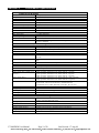
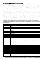
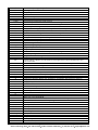
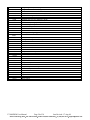
Section 2 Performance Specifications Telephone Line (All models) Max. Data Rate 33.6 kbps (V.34) Compatibility V.34, V.32bis, V.32, V.22bis, V.22A/B, V.23, V.21, Bell212A & 103 Data Compression V.44/V.42bis/MNP 5 Error Correction V.42/MNP 2-4 Max Fax Modem Rate 14.4 kbps (V.33) Fax Modem Compatibility Group 3 (V.33, V.17, V.29, V.27ter, V.21 ch. 2) Ringer Equivalent 0.3 Line Jack RJ11 Phone Jack RJ11 (VT-MODEM-1 and –2) RS232 Port (All models) Max. RS232 Rate 115.2 kbps (Kilobaud) RS232 Signal Support TXD, RXD, CTS, RTS, DCD, DTR, DSR, RI, GND RS232 Connector DB9 female, RS232 Command Set All standard AT and S register commands including Class 1, Class 2 Fax commands and Voice commands RS422 / RS485 Port (VT-MODEM-3 only) RS422 mode 4 wire full duplex RS485 modes 2 or 4 wire party-line operation (half duplex) Signal rate Standard rates up to 115.2 kbps (Kilobaud) RS422 / RS485 distance Up to 0.5 miles Status LEDs (All models) CD (Carrier detect) The modem has detected a carrier on the phone line (a remote modem has been detected). TR (Data Terminal Ready) The PC (or Gateway/VersaTRAK) has established a connection to the modem and is ready. RD (Receive Data) Flashes as data is received from the phone line. TD (Transmit Data) Flashes as data is sent out the phone line. Power On when power is present. General Characteristics (All models) Input Power 10 - 30 VDC (VT-MODEM-1, –2), 10 – 52 VDC (VT-MODEM-3) Input Current (Rev 1 and Rev2, see 65mA @ 24VDC and 26mA in Low Power mode of –1 (typical) section 1) 97mA @ 24VDC and 64mA in Low Power mode of –2 (typical) 68mA @ 24VDC and 28mA in Low Power mode of –3 (typical) Input Current (Rev 3) 50mA @ 24VDC and 30mA in Low Power mode for -1 and -2 (typical) 55mA @ 24VDC and 35mA in Low Power mode for -3 (typical) Certification FCC Part 15 and FCC Part 68; UL 508; CSA C22.2/14; ACA TS 001- 1997; ACA TS 002-1997; AS/NZS3260-1993; AS/NZS3548-1995; CTR21 (98/482/EC); EN55022; IEC 950:1991. Operating Temperature -30 ° to 70 ° C Storage Temperature -40 ° to 85 ° C Humidity 5 to 95% RH (non-condensing) Mounting DIN rail or panel mount Dimensions W x 4.75L x 1.35H inches (8.2 W x 12.1 L x 3.4H cm) PLC Discrete I/O Interface (VT-MODEM-2 only) Trigger Input (From PLC) Connects to PLC output. Starts auto-dialing upon transition from OFF to ON. Modem will stay connected while input is ON. Voltage Range 9 to 30 VDC Input Current 6.5 mA at 24 VDC Max. OFF Voltage 5 VDC On-line Output (To PLC) Output is ON as long as a connection exists (carrier detect). Output Characteristics Sourcing – switches supply power Max. Output Current 100 mA VT-MODEM User Manual Page 5 of 30 Last Revised: 17-Aug-09 Sixnet Technology Park 331 Ushers Road Clifton Park, NY 12065 USA +1 (518) 877-5173 [email protected]