1
PNX17xx Series
Data Book
Volume 1 of 1
Connected Media Processor
Rev. 1.11 — 05 February 2007
PNX17xx Series
NXP Semiconductors
Volume 1 of 1
Connected Media Processor
PNX17XX_SER_1.11
Preliminary data sheet
© NXP B.V. 2007. All rights reserved.
Rev. 1.11 — 05 February 2007
-ii
PNX17xx Series
NXP Semiconductors
Volume 1 of 1
Connected Media Processor
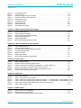
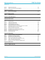
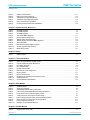
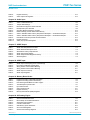
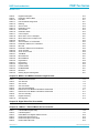
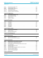
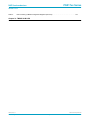
Table of Contents
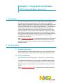
Chapter 1: Integrated Circuit Data
1.
2.
2.1
2.2
2.3
2.3.1
2.3.2
3.
4.
4.1
4.2
4.3
4.4
5.
5.1
5.2
5.3
5.4
5.4.1
5.4.2
6.
6.1
6.2
6.3
6.4
6.5
6.6
6.7
6.8
Introduction. . . . . . . . . . . . . . . . . . . . . . . . . . . . . . 1-1
Pin Description . . . . . . . . . . . . . . . . . . . . . . . . . . 1-1
Boundary Scan Notice . . . . . . . . . . . . . . . . . . . . . 1-1
I/O Circuit Summary . . . . . . . . . . . . . . . . . . . . . . . 1-1
Signal Pin List . . . . . . . . . . . . . . . . . . . . . . . . . . . . 1-3
Power Pin List . . . . . . . . . . . . . . . . . . . . . . . . . . . 1-19
Pin Reference Voltage . . . . . . . . . . . . . . . . . . . . 1-20
Absolute Maximum Ratings . . . . . . . . . . . . 1-20
PNX17xx Series Operating Conditions . 1-21
PNX1700 Device
PNX1701 Device
PNX1702 Device
PNX1703 Device
........................
........................
........................
........................
1-22
1-23
1-23
1-24
Power Considerations . . . . . . . . . . . . . . . . . . 1-24
Power Supply Sequencing . . . . . . . . . . . . . . . .
Leakage current Power Consumption . . . . . .
Standby Power Consumption . . . . . . . . . . . . . .
Power Consumption . . . . . . . . . . . . . . . . . . . . . .
Typical Power Consumption for Typical
Applications1-25
Expected Maximum Currents . . . . . . . . . . . . . .
1-24
1-25
1-25
1-25
1-26
DC/AC I/O Characteristics . . . . . . . . . . . . . . 1-27
Input Clock Specification . . . . . . . . . . . . . . . . . . 1-27
SSTL_2 type I/O Circuit . . . . . . . . . . . . . . . . . . . 1-28
BPX2T14MCP Type I/O Circuit . . . . . . . . . . . . 1-29
BPTS1CHP and BPTS1CP Type I/O Circuit . 1-30
BPTS3CHP and BPTS3CP Type I/O Circuit . 1-31
IPCHP and IPCP Type I/O Circuit . . . . . . . . . . 1-32
BPT3MCHDT5V and BPT3MCHT5V Type I/O
Circuit1-32
IIC3M4SDAT5V and IIC3M4SCLT5V type I/O
circuit1-33
6.9
7.
7.1
7.2
7.3
7.4
7.5
7.6
7.7
7.8
7.9
7.10
7.11
7.12
7.13
8.
9.
10.
10.1
10.2
10.2.1
10.2.2
10.3
10.3.1
10.3.2
10.4
PCIT5V type I/O circuit . . . . . . . . . . . . . . . . . . . . 1-33
I/O Timing Specification
. . . . . . . . . . . . . . . . 1-33
Reset . . . . . . . . . . . . . . . . . . . . . . . . . . . . . . . . . . . 1-34
DDR DRAM Interface . . . . . . . . . . . . . . . . . . . . . 1-34
PCI Bus Interface . . . . . . . . . . . . . . . . . . . . . . . . 1-35
QVCP, LCD and FGPO Interfaces . . . . . . . . . . 1-37
VIP and FGPI Interfaces . . . . . . . . . . . . . . . . . . 1-38
10/100 LAN In MII Mode . . . . . . . . . . . . . . . . . . 1-39
10/100 LAN In RMII Mode . . . . . . . . . . . . . . . . . 1-40
Audio Input Interface . . . . . . . . . . . . . . . . . . . . . 1-40
Audio Output Interface . . . . . . . . . . . . . . . . . . . . 1-41
SPDIF I/O Interface . . . . . . . . . . . . . . . . . . . . . . 1-42
I2C I/O Interface . . . . . . . . . . . . . . . . . . . . . . . . . 1-43
GPIO Interface . . . . . . . . . . . . . . . . . . . . . . . . . . . 1-44
JTAG Interface. . . . . . . . . . . . . . . . . . . . . . . . . . . 1-45
Package Outline . . . . . . . . . . . . . . . . . . . . . . . . . 1-46
BGA Ball Assignment . . . . . . . . . . . . . . . . . . . 1-47
Board Design Guidelines . . . . . . . . . . . . . . . 1-49
Power Supplies Decoupling . . . . . . . . . . . . . . . 1-49
Analog Supplies. . . . . . . . . . . . . . . . . . . . . . . . . . 1-50
The 3.3 V Analog Supply . . . . . . . . . . . . . . . . . . 1-50
The SoC Core, VDDA, Analog Supply . . . . . . 1-50
DDR SDRAM interface . . . . . . . . . . . . . . . . . . . . 1-51
Do DDR Devices Require Termination? . . . . . 1-52
What if I really want to use termination for the
PNX17xx Series?1-52
Package Handling, Soldering and Thermal
Properties1-53
11.
12.
13.
Miscellaneous . . . . . . . . . . . . . . . . . . . . . . . . . . . 1-53
Soft Errors Due to Radiation . . . . . . . . . . . . 1-53
Ordering Information. . . . . . . . . . . . . . . . . . . . 1-54
6.2
DVD De-scrambler . . . . . . . . . . . . . . . . . . . . . . . 2-12
Chapter 2: Overview
1.
1.1
1.2
2.
Introduction. . . . . . . . . . . . . . . . . . . . . . . . . . . . . . 2-1
PNX17xx Series Functional Overview . . . . . . . 2-1
PNX17xx Series Features Summary . . . . . . . . 2-3
PNX17xx Series Functional Block Diagram
2-5
3.
3.1
3.2
3.3
3.4
3.5
3.6
4.
4.1
4.2
5.
6.
6.1
System Resources. . . . . . . . . . . . . . . . . . . . . . . 2-6
System Reset . . . . . . . . . . . . . . . . . . . . . . . . . . . .
System Booting . . . . . . . . . . . . . . . . . . . . . . . . . . .
Clock System . . . . . . . . . . . . . . . . . . . . . . . . . . . .
Power Management . . . . . . . . . . . . . . . . . . . . . . .
Semaphores . . . . . . . . . . . . . . . . . . . . . . . . . . . . .
I2C Interface . . . . . . . . . . . . . . . . . . . . . . . . . . . . .
System Memory
2-6
2-6
2-7
2-7
2-8
2-8
. . . . . . . . . . . . . . . . . . . . . . . . . 2-9
MMI - Main Memory Interface . . . . . . . . . . . . . . 2-9
Flash . . . . . . . . . . . . . . . . . . . . . . . . . . . . . . . . . . . . 2-9
TM5250 VLIW Media Processor Core . . . 2-10
MPEG Decoding . . . . . . . . . . . . . . . . . . . . . . . . 2-11
VLD . . . . . . . . . . . . . . . . . . . . . . . . . . . . . . . . . . . . 2-12
7.
7.1
7.2
7.3
7.4
7.5
7.5.1
Image Processing . . . . . . . . . . . . . . . . . . . . . . . 2-12
Pixel Format . . . . . . . . . . . . . . . . . . . . . . . . . . . . . 2-12
Video Input Processor . . . . . . . . . . . . . . . . . . . . 2-13
Memory Based Scaler . . . . . . . . . . . . . . . . . . . . 2-14
2D Drawing and DMA Engine . . . . . . . . . . . . . . 2-15
Quality Video Composition Processor . . . . . . . 2-15
External Video Improvement Post Processing . 216
8.
8.1
8.2
9.
Audio processing and Input/Output
General Purpose Interfaces . . . . . . . . . . . . . 2-18
9.1
9.2
9.3
9.4
Video/Data Input Router . . . . . . . . . . . . . . . . . . 2-18
Video/Data Output Router . . . . . . . . . . . . . . . . . 2-19
Fast General Purpose Input . . . . . . . . . . . . . . . 2-20
Fast General Purpose Output . . . . . . . . . . . . . . 2-21
10.
Peripheral Interface . . . . . . . . . . . . . . . . . . . . . 2-21
PNX17XX_SER_1.11
Preliminary data sheet
. . . . 2-17
Audio Processing . . . . . . . . . . . . . . . . . . . . . . . . 2-17
Audio Inputs and Outputs . . . . . . . . . . . . . . . . . 2-17
© NXP B.V. 2007. All rights reserved.
Rev. 1.11 — 05 February 2007
-3
PNX17xx Series
NXP Semiconductors
Volume 1 of 1
10.1
10.1.1
10.1.2
10.1.3
10.1.4
10.2
GPIO - General Purpose Software I/O and
Flexible Serial Interface2-21
software I/O . . . . . . . . . . . . . . . . . . . . . . . . . . . . . 2-21
timestamping . . . . . . . . . . . . . . . . . . . . . . . . . . . . 2-22
event sequence monitoring and signal generation
10.3
10.3.1
10.3.2
10.3.3
10.4
2-22
11.
12.
Endian Modes . . . . . . . . . . . . . . . . . . . . . . . . . . . 2-26
System Debug . . . . . . . . . . . . . . . . . . . . . . . . . . 2-27
5.4
5.5
Usage Notes . . . . . . . . . . . . . . . . . . . . . . . . . . . . 3-10
Semaphore MMIO Registers. . . . . . . . . . . . . . . 3-11
GPIO pin reset value . . . . . . . . . . . . . . . . . . . . . 2-22
IR Remote Control Receiver and Blaster . . . . 2-23
PCI-2.2 & XIO-16 Bus Interface Unit . . . . . . . . 2-23
PCI Capabilities . . . . . . . . . . . . . . . . . . . . . . . . . . 2-23
Simple Peripheral Capabilities (‘XIO-8/16’) . . 2-24
IDE Drive Interface . . . . . . . . . . . . . . . . . . . . . . . 2-26
10/100 Ethernet MAC . . . . . . . . . . . . . . . . . . . . . 2-26
Chapter 3: System On Chip Resources
1.
2.
2.1
2.2
2.3
2.4
2.4.1
2.5
3.
3.1
3.2
3.3
4.
4.1
5.
5.1
5.2
5.3
Introduction. . . . . . . . . . . . . . . . . . . . . . . . . . . . . . 3-1
System Memory Map . . . . . . . . . . . . . . . . . . . . 3-1
The PCI View . . . . . . . . . . . . . . . . . . . . . . . . . . . . 3-2
The CPU View. . . . . . . . . . . . . . . . . . . . . . . . . . . . 3-3
The DCS View Or The System View . . . . . . . . 3-4
The Programmable DCS Apertures . . . . . . . . . 3-5
DCS DRAM Aperture Control MMIO Registers 3-6
Aperture Boundaries . . . . . . . . . . . . . . . . . . . . . . 3-6
System Principles
.......................
Module ID . . . . . . . . . . . . . . . . . . . . . . . . . . . . . . . .
Powerdown bit. . . . . . . . . . . . . . . . . . . . . . . . . . . .
System Module MMIO registers . . . . . . . . . . . .
3-7
3-7
3-7
3-8
6.
6.1
6.2
6.3
6.3.1
System Related Information for TM5250 3-12
Interrupts . . . . . . . . . . . . . . . . . . . . . . . . . . . . . . . . 3-12
Timers . . . . . . . . . . . . . . . . . . . . . . . . . . . . . . . . . . 3-14
System Parameters for TM5250 . . . . . . . . . . . 3-15
TM5250 System Parameters MMIO Registers . 316
7.
Video Input and Output Routers . . . . . . . . 3-16
7.1
MMIO Registers for the Input/Output Video/Data
Router3-17
8.
Miscellaneous . . . . . . . . . . . . . . . . . . . . . . . . . . . 3-26
System Endian Mode . . . . . . . . . . . . . . . . . . . . 3-8
8.1
Miscellaneous System MMIO registers . . . . . . 3-27
System Endian Mode MMIO registers . . . . . . . 3-9
9.
10.
11.
12.
System Registers Map Summary . . . . . . . 3-29
Simplified Internal Bus Infrastructure . . 3-30
MMIO Memory MAP . . . . . . . . . . . . . . . . . . . . . 3-31
References . . . . . . . . . . . . . . . . . . . . . . . . . . . . . . 3-32
System Semaphores
. . . . . . . . . . . . . . . . . . . . 3-9
Semaphore Specification . . . . . . . . . . . . . . . . . . 3-9
Construction of a 12-bit ID . . . . . . . . . . . . . . . . . 3-9
The Master Semaphore . . . . . . . . . . . . . . . . . . . 3-10
Chapter 4: Reset
1.
2.
2.1
2.2
2.2.1
2.2.2
2.3
Introduction. . . . . . . . . . . . . . . . . . . . . . . . . . . . . . 4-1
Functional Description . . . . . . . . . . . . . . . . . . 4-1
RESET_IN_N or POR_IN_N? . . . . . . . . . . . . . .
The watchdog Timer . . . . . . . . . . . . . . . . . . . . . .
The Non Interrupt Mode . . . . . . . . . . . . . . . . . . .
The Interrupt Mode . . . . . . . . . . . . . . . . . . . . . . . .
The Software Reset . . . . . . . . . . . . . . . . . . . . . . .
4-3
4-4
4-4
4-5
4-6
2.4
3.
3.1
3.2
4.
5.
The External Software Reset . . . . . . . . . . . . . . . 4-6
Timing Description . . . . . . . . . . . . . . . . . . . . . . . 4-7
The Hardware Timing . . . . . . . . . . . . . . . . . . . . . . 4-7
The Software Timing . . . . . . . . . . . . . . . . . . . . . . 4-8
Register Definitions . . . . . . . . . . . . . . . . . . . . . . 4-9
References . . . . . . . . . . . . . . . . . . . . . . . . . . . . . . 4-10
Chapter 5: The Clock Module
1.
2.
2.1
2.2
2.2.1
2.2.2
2.2.3
2.2.4
2.2.5
2.3
2.4
2.5
2.6
2.7
2.8
Introduction. . . . . . . . . . . . . . . . . . . . . . . . . . . . . . 5-1
Functional Description . . . . . . . . . . . . . . . . . . 5-1
The Modules and their Clocks . . . . . . . . . . . . . . 5-4
Clock Sources for PNX17xx Series. . . . . . . . . . 5-7
PLL Specification . . . . . . . . . . . . . . . . . . . . . . . . . 5-8
The Clock Dividers . . . . . . . . . . . . . . . . . . . . . . . 5-10
The DDS Clocks . . . . . . . . . . . . . . . . . . . . . . . . . 5-11
DDS and PLL Assignment Summary . . . . . . . 5-11
External Clocks . . . . . . . . . . . . . . . . . . . . . . . . . . 5-11
Clock Control Logic . . . . . . . . . . . . . . . . . . . . . . 5-13
Bypass Clock Sources . . . . . . . . . . . . . . . . . . . . 5-14
Power-up and Reset sequence . . . . . . . . . . . . 5-15
Clock Stretching . . . . . . . . . . . . . . . . . . . . . . . . . 5-15
Clock Frequency Determination . . . . . . . . . . . 5-16
Power Down . . . . . . . . . . . . . . . . . . . . . . . . . . . . 5-17
2.8.1
2.9
2.10
2.11
2.11.1
2.11.2
2.12
2.12.1
2.12.2
2.12.3
2.12.4
2.12.5
2.12.6
3.
Wake-Up from Power Down . . . . . . . . . . . . . . . 5-17
Clock Detection . . . . . . . . . . . . . . . . . . . . . . . . . . 5-18
VDO Clocks . . . . . . . . . . . . . . . . . . . . . . . . . . . . . 5-19
GPIO Clocks . . . . . . . . . . . . . . . . . . . . . . . . . . . . 5-20
Setting GPIO[14:12]/GCLOCK[2:0] as Clock
Outputs5-20
GPIO[6:4]/CLOCK[6:4] as Clock Outputs . . . . 5-20
Clock Block Diagrams . . . . . . . . . . . . . . . . . . . . 5-21
TM5250, DDR and QVCP clocks . . . . . . . . . . . 5-22
Clock Dividers . . . . . . . . . . . . . . . . . . . . . . . . . . . 5-24
Internal PNX17xx Series Clock from Dividers 5-25
GPIO Clocks . . . . . . . . . . . . . . . . . . . . . . . . . . . . 5-27
External Clocks . . . . . . . . . . . . . . . . . . . . . . . . . . 5-28
SPDO . . . . . . . . . . . . . . . . . . . . . . . . . . . . . . . . . . 5-32
Registers Definition . . . . . . . . . . . . . . . . . . . . . 5-32
PNX17XX_SER_1.11
Preliminary data sheet
© NXP B.V. 2007. All rights reserved.
Rev. 1.11 — 05 February 2007
-4
PNX17xx Series
NXP Semiconductors
Volume 1 of 1
3.1
Registers Summary . . . . . . . . . . . . . . . . . . . . . . 5-32
3.2
Registers Description . . . . . . . . . . . . . . . . . . . . . 5-35
3.2
The Specifics of the Boot From Flash Memory
Devices6-10
Binary Sequence for the Section of the Flash Boot
Chapter 6: Boot Module
1.
2.
2.1
2.2
2.2.1
2.2.2
2.2.3
2.3
3.
3.1
3.1.1
Introduction. . . . . . . . . . . . . . . . . . . . . . . . . . . . . . 6-1
Functional Description . . . . . . . . . . . . . . . . . . 6-1
The Boot Modes . . . . . . . . . . . . . . . . . . . . . . . . . .
Boot Module Operation . . . . . . . . . . . . . . . . . . . .
MMIO Bus Interface . . . . . . . . . . . . . . . . . . . . . . .
I2C Master . . . . . . . . . . . . . . . . . . . . . . . . . . . . . . .
Boot Control/State Machine . . . . . . . . . . . . . . . .
The Boot Command Language . . . . . . . . . . . . .
6-2
6-4
6-4
6-4
6-5
6-5
PNX17xx Series Boot Scripts Content. . . 6-6
The Common Behavior . . . . . . . . . . . . . . . . . . . . 6-6
Binary Sequence for the Common Boot Script 6-9
3.2.1
6-12
3.3
4.
4.1
4.2
4.3
The Specifics of the Host-Assisted Mode . . . . 6-12
The Boot From an I2C EEPROM
. . . . . . . . 6-14
External I2C Boot EEPROM Types . . . . . . . . . 6-14
The Boot Commands and The Endian Mode . 6-15
Details on I2C Operation . . . . . . . . . . . . . . . . . . 6-15
5.
References . . . . . . . . . . . . . . . . . . . . . . . . . . . . . . 6-16
4.
Application Notes . . . . . . . . . . . . . . . . . . . . . . . 7-19
Chapter 7: PCI-XIO Module
1.
2.
2.1
2.2
3.
3.1
3.1.1
3.1.2
3.1.3
3.1.4
3.2
Introduction. . . . . . . . . . . . . . . . . . . . . . . . . . . . . . 7-1
Functional Description . . . . . . . . . . . . . . . . . . 7-2
Document title variable Block Level Diagram . 7-3
Architecture . . . . . . . . . . . . . . . . . . . . . . . . . . . . . . 7-3
Operation . . . . . . . . . . . . . . . . . . . . . . . . . . . . . . . . 7-4
Overview . . . . . . . . . . . . . . . . . . . . . . . . . . . . . . . . 7-4
NAND-Flash Interface Operation . . . . . . . . . . . . 7-5
Motorola Style Interface . . . . . . . . . . . . . . . . . . 7-10
NOR Flash Interface . . . . . . . . . . . . . . . . . . . . . 7-12
IDE Description . . . . . . . . . . . . . . . . . . . . . . . . . . 7-13
PCI Interrupt Enable Register . . . . . . . . . . . . . 7-18
4.1
4.2
4.3
4.3.1
4.3.2
4.3.3
4.3.4
4.4
4.5
5.
DTL Interface . . . . . . . . . . . . . . . . . . . . . . . . . . . . 7-19
System Memory Bus Interface, the MTL Bus 7-19
XIO Interface . . . . . . . . . . . . . . . . . . . . . . . . . . . . 7-20
Motorola Interface . . . . . . . . . . . . . . . . . . . . . . . . 7-20
NAND-Flash Interface . . . . . . . . . . . . . . . . . . . . 7-20
NOR Flash Interface . . . . . . . . . . . . . . . . . . . . . . 7-20
IDE Interface . . . . . . . . . . . . . . . . . . . . . . . . . . . . 7-21
PCI Endian Support . . . . . . . . . . . . . . . . . . . . . . 7-21
General Notes . . . . . . . . . . . . . . . . . . . . . . . . . . . 7-21
Register Descriptions . . . . . . . . . . . . . . . . . . . 7-21
5.1
Register Summary . . . . . . . . . . . . . . . . . . . . . . . 7-22
3.1
3.2
Duty-cycle programming . . . . . . . . . . . . . . . . . . 8-19
Spike Filtering . . . . . . . . . . . . . . . . . . . . . . . . . . . 8-20
Chapter 8: General Purpose Input Output Pins
1.
2.
2.1
2.1.1
2.1.2
2.1.3
2.2
2.2.1
2.2.2
2.3
2.3.1
2.3.2
2.4
2.4.1
2.5
2.6
2.7
2.8
2.9
3.
Introduction. . . . . . . . . . . . . . . . . . . . . . . . . . . . . . 8-1
Functional Description . . . . . . . . . . . . . . . . . . 8-2
GPIO: The Basic Pin Behavior . . . . . . . . . . . . . . 8-2
GPIO Mode settings . . . . . . . . . . . . . . . . . . . . . . . 8-4
GPIO Data Settings MMIO Registers . . . . . . . . 8-4
GPIO Pin Status Reading . . . . . . . . . . . . . . . . . . 8-6
GPIO: The Event Monitoring Mode . . . . . . . . . . 8-6
Timestamp Reference clock . . . . . . . . . . . . . . . . 8-7
Timestamp format. . . . . . . . . . . . . . . . . . . . . . . . . 8-7
GPIO: The Signal Monitoring & Pattern
Generation Modes8-7
The Signal Monitoring Mode. . . . . . . . . . . . . . . . 8-8
The Signal Pattern Generation Mode . . . . . . . 8-11
GPIO Error Behaviour . . . . . . . . . . . . . . . . . . . . 8-14
GPIO Frequency Restrictions. . . . . . . . . . . . . . 8-15
The GPIO Clock Pins . . . . . . . . . . . . . . . . . . . . . 8-17
GPIO Interrupts . . . . . . . . . . . . . . . . . . . . . . . . . . 8-17
Timer Sources . . . . . . . . . . . . . . . . . . . . . . . . . . . 8-18
Wake-up Interrupt . . . . . . . . . . . . . . . . . . . . . . . . 8-18
External Watchdog . . . . . . . . . . . . . . . . . . . . . . . 8-18
IR Applications
. . . . . . . . . . . . . . . . . . . . . . . . . 8-18
4.
4.1
4.2
4.3
4.4
4.5
4.6
4.7
4.8
4.9
4.10
4.11
4.12
4.13
4.14
4.15
MMIO Registers . . . . . . . . . . . . . . . . . . . . . . . . . 8-21
GPIO Mode Control Registers . . . . . . . . . . . . . 8-24
GPIO Data Control . . . . . . . . . . . . . . . . . . . . . . . 8-26
Readable Internal PNX17xx Series Signals . . 8-26
Sampling and Pattern Generation Control
Registers for the FIFO Queues8-27
Signal and Event Monitoring Control Registers for
the Timestamp Units8-34
Timestamp Unit Registers . . . . . . . . . . . . . . . . . 8-34
GPIO Time Counter . . . . . . . . . . . . . . . . . . . . . . 8-34
GPIO TM5250 Timer Input Select . . . . . . . . . . 8-35
GPIO Interrupt Status . . . . . . . . . . . . . . . . . . . . . 8-35
Clock Out Select . . . . . . . . . . . . . . . . . . . . . . . . . 8-36
GPIO Interrupt Registers for the FIFO Queues
(One for each FIFO Queue)8-37
GPIO Module Status Register for all 12
Timestamp Units8-38
GPIO POWERDOWN . . . . . . . . . . . . . . . . . . . . 8-43
GPIO Module ID . . . . . . . . . . . . . . . . . . . . . . . . . 8-43
GPIO IO_SEL Selection Values . . . . . . . . . . . . 8-43
PNX17XX_SER_1.11
Preliminary data sheet
© NXP B.V. 2007. All rights reserved.
Rev. 1.11 — 05 February 2007
-5
PNX17xx Series
NXP Semiconductors
Volume 1 of 1
Chapter 9: DDR Controller
1.
2.
2.1
2.1.1
2.1.2
2.1.3
2.2
2.2.1
2.2.2
2.2.3
2.2.4
2.2.5
2.2.6
Introduction. . . . . . . . . . . . . . . . . . . . . . . . . . . . . . 9-1
Functional Description . . . . . . . . . . . . . . . . . . 9-1
Start and Warm Start . . . . . . . . . . . . . . . . . . . . . . 9-2
The Start Mode . . . . . . . . . . . . . . . . . . . . . . . . . . . 9-2
Warm Start . . . . . . . . . . . . . . . . . . . . . . . . . . . . . . . 9-2
Observing Start State . . . . . . . . . . . . . . . . . . . . . 9-3
Arbitration . . . . . . . . . . . . . . . . . . . . . . . . . . . . . . . . 9-3
The First Level of Arbitration: Between the DMA
and the CPU9-3
Second Level of Arbitration. . . . . . . . . . . . . . . . . 9-6
Dynamic Ratios . . . . . . . . . . . . . . . . . . . . . . . . . . . 9-6
Pre-Emption . . . . . . . . . . . . . . . . . . . . . . . . . . . . . . 9-8
Back Log Buffer (BLB) . . . . . . . . . . . . . . . . . . . . . 9-9
PMAN (Hub) versus DDR Controller Interaction 99
2.3
2.3.1
2.3.2
2.4
2.5
2.5.1
2.5.2
2.5.3
2.5.4
Addressing . . . . . . . . . . . . . . . . . . . . . . . . . . . . . .
Memory Region Mapping Scheme . . . . . . . . .
DDR Memory Rank Locations . . . . . . . . . . . . .
Clock Programming . . . . . . . . . . . . . . . . . . . . . .
Power Management . . . . . . . . . . . . . . . . . . . . . .
Halting and Unhalting . . . . . . . . . . . . . . . . . . . .
MMIO Directed Halt . . . . . . . . . . . . . . . . . . . . . .
Auto Halt . . . . . . . . . . . . . . . . . . . . . . . . . . . . . . .
Observing Halt Mode . . . . . . . . . . . . . . . . . . . . .
9-10
9-10
9-12
9-13
9-13
9-14
9-14
9-14
9-15
2.5.5
3.
3.1
3.2
3.3
3.4
3.5
3.6
4.
4.0.1
4.1
4.2
4.3
4.4
4.5
4.6
4.7
5.
5.1
5.2
6.
Sequence of Actions . . . . . . . . . . . . . . . . . . . . . . 9-16
Application Notes . . . . . . . . . . . . . . . . . . . . . . . 9-16
Memory Configurations . . . . . . . . . . . . . . . . . . . 9-16
Error Signaling . . . . . . . . . . . . . . . . . . . . . . . . . . . 9-17
Latency . . . . . . . . . . . . . . . . . . . . . . . . . . . . . . . . . 9-17
Data Coherency. . . . . . . . . . . . . . . . . . . . . . . . . . 9-18
Programming the Internal Arbiter . . . . . . . . . . . 9-18
The DDR Controller and the DDR Memory
Devices9-20
Timing Diagrams and Tables. . . . . . . . . . . . 9-20
Tcas Timing Parameter . . . . . . . . . . . . . . . . . . . 9-21
Trrd and Trc Timing Parameters . . . . . . . . . . . 9-21
Trfc Timing Parameter . . . . . . . . . . . . . . . . . . . . 9-21
Twr Timing Parameter . . . . . . . . . . . . . . . . . . . . 9-22
Tras Timing Parameter . . . . . . . . . . . . . . . . . . . 9-22
Trp Timing Parameter . . . . . . . . . . . . . . . . . . . . 9-22
Trcd_rd Timing Parameter. . . . . . . . . . . . . . . . . 9-23
Trcd_wr Timing Parameter . . . . . . . . . . . . . . . . 9-23
Register Descriptions . . . . . . . . . . . . . . . . . . . 9-23
Register Summary . . . . . . . . . . . . . . . . . . . . . . . 9-24
Register Table . . . . . . . . . . . . . . . . . . . . . . . . . . . 9-25
References . . . . . . . . . . . . . . . . . . . . . . . . . . . . . . 9-32
Chapter 10: LCD Controller
1.
1.1
2.
2.1
2.2
3.
3.1
3.2
Introduction. . . . . . . . . . . . . . . . . . . . . . . . . . . . . 10-1
LCD Controller Features . . . . . . . . . . . . . . . . . . 10-1
Functional Description
. . . . . . . . . . . . . . . . . 10-1
Overview . . . . . . . . . . . . . . . . . . . . . . . . . . . . . . . 10-1
Power Sequencing . . . . . . . . . . . . . . . . . . . . . . . 10-2
Operation . . . . . . . . . . . . . . . . . . . . . . . . . . . . . . . 10-3
Overview . . . . . . . . . . . . . . . . . . . . . . . . . . . . . . . 10-3
Power Sequencing State Machine . . . . . . . . . 10-3
3.2.1
3.2.2
3.2.3
3.2.4
3.3
3.4
4.
IDLE state . . . . . . . . . . . . . . . . . . . . . . . . . . . . . . . 10-4
DCEN state . . . . . . . . . . . . . . . . . . . . . . . . . . . . . 10-4
BLEN state . . . . . . . . . . . . . . . . . . . . . . . . . . . . . . 10-5
PEPED state . . . . . . . . . . . . . . . . . . . . . . . . . . . . 10-5
Counter . . . . . . . . . . . . . . . . . . . . . . . . . . . . . . . . . 10-5
Gating Logic . . . . . . . . . . . . . . . . . . . . . . . . . . . . . 10-5
Register Descriptions . . . . . . . . . . . . . . . . . . . 10-6
4.1
LCD MMIO Registers . . . . . . . . . . . . . . . . . . . . . 10-7
2.4.2
DCTI (Digital Chroma/Color Transient
Improvement)11-13
HSRU (Horizontal Sample Rate Upconverter). 11-
Chapter 11: QVCP
1.
1.1
2.
2.1
2.2
2.3
2.3.1
2.3.2
2.3.3
2.3.4
2.3.5
2.3.6
2.3.7
2.4
2.4.1
Introduction. . . . . . . . . . . . . . . . . . . . . . . . . . . . . 11-1
Features . . . . . . . . . . . . . . . . . . . . . . . . . . . . . . . . 11-2
Functional Description
.................
QVCP Block Diagram . . . . . . . . . . . . . . . . . . . .
Architecture . . . . . . . . . . . . . . . . . . . . . . . . . . . . .
Layer Resources and Functions . . . . . . . . . . .
Memory Access Control (DMA CTRL) . . . . . .
Pixel Formatter Unit (PFU) . . . . . . . . . . . . . . . .
11-4
11-4
11-5
11-6
11-6
11-7
Chroma Key and Undither (CKEY/UDTH) Unit 117
Chroma Upsample Filter (CUPS) . . . . . . . . . 11-11
Linear Interpolator (LINT) . . . . . . . . . . . . . . . . 11-11
Video/Graphics Contrast Brightness Matrix
(VCBM)11-11
Layer and Fetch Control . . . . . . . . . . . . . . . . . 11-12
Pool Resources and Functions . . . . . . . . . . . 11-13
CLUT (Color Look Up Table) . . . . . . . . . . . . . 11-13
2.4.3
13
2.4.4
2.4.5
2.4.6
2.4.7
2.5
2.6
2.6.1
2.6.2
2.7
2.7.1
2.7.2
2.7.3
2.7.4
HIST (Histogram Modification) Unit . . . . . . . . 11-14
LSHR (Luminance/Luma Sharpening) Unit . 11-14
Color Features (CFTR) Unit . . . . . . . . . . . . . . 11-14
PLAN (Semi Planar DMA) Unit . . . . . . . . . . . . 11-15
Screen Timing Generator . . . . . . . . . . . . . . . . 11-15
Mixer Structure . . . . . . . . . . . . . . . . . . . . . . . . . 11-16
Key Generation . . . . . . . . . . . . . . . . . . . . . . . . . 11-18
Alpha Blending. . . . . . . . . . . . . . . . . . . . . . . . . . 11-19
Output Pipeline Structure. . . . . . . . . . . . . . . . . 11-19
Supported Output Formats . . . . . . . . . . . . . . . 11-20
Layer Selection . . . . . . . . . . . . . . . . . . . . . . . . . 11-20
Chrominance Downsampling (CDNS) . . . . . . 11-20
Gamma Correction and Noise Shaping (GNSH&
ONSH)11-20
PNX17XX_SER_1.11
Preliminary data sheet
© NXP B.V. 2007. All rights reserved.
Rev. 1.11 — 05 February 2007
-6
PNX17xx Series
NXP Semiconductors
Volume 1 of 1
2.7.5
2.7.6
3.
Output Interface Modes . . . . . . . . . . . . . . . . . . 11-21
Auxiliary Pins . . . . . . . . . . . . . . . . . . . . . . . . . . . 11-22
MMIO and Task Based Programming . . . . . 11-23
Setup Order for the QVCP . . . . . . . . . . . . . . . 11-24
Shadow Registers . . . . . . . . . . . . . . . . . . . . . . 11-25
Fast Access Registers . . . . . . . . . . . . . . . . . . . 11-29
Programming of Layer and Pool Resources 11-30
Resource Assignment and Selection . . . . . . 11-30
Aperture Assignment . . . . . . . . . . . . . . . . . . . . 11-30
Data Flow Selection . . . . . . . . . . . . . . . . . . . . . 11-32
Pool Resource Assignment Example . . . . . . 11-34
Programming the STG . . . . . . . . . . . . . . . . . . . 11-35
Changing Timing. . . . . . . . . . . . . . . . . . . . . . . . 11-36
Programming QVCP for Different Output Formats
4.1
4.1.1
4.2
4.3
4.4
4.5
4.6
4.7
4.8
4.8.1
4.8.2
4.8.3
4.8.4
4.8.5
4.9
4.10
11-36
5.
Programming and Resource Assignment . .
11-23
3.1
3.2
3.2.1
3.2.2
3.3
3.3.1
3.3.2
3.3.3
3.3.4
3.4
3.4.1
3.5
4.
Application Notes. . . . . . . . . . . . . . . . . . . . . . 11-37
Special Features . . . . . . . . . . . . . . . . . . . . . . . . 11-37
Signature Analysis . . . . . . . . . . . . . . . . . . . . . . 11-37
Programming Help . . . . . . . . . . . . . . . . . . . . . . 11-37
LINT Parameters . . . . . . . . . . . . . . . . . . . . . . . . 11-38
HSRU Parameters . . . . . . . . . . . . . . . . . . . . . . 11-38
LSHR Parameters . . . . . . . . . . . . . . . . . . . . . . . 11-39
DCTI Parameters . . . . . . . . . . . . . . . . . . . . . . . 11-40
CFTR Parameters . . . . . . . . . . . . . . . . . . . . . . . 11-40
Underflow Behavior . . . . . . . . . . . . . . . . . . . . . 11-40
Layer Underflow . . . . . . . . . . . . . . . . . . . . . . . . 11-41
Underflow Symptom . . . . . . . . . . . . . . . . . . . . . 11-41
Underflow Recovery . . . . . . . . . . . . . . . . . . . . . 11-41
Underflow Trouble-shooting . . . . . . . . . . . . . . 11-41
Underflow Handling . . . . . . . . . . . . . . . . . . . . . 11-41
Setting QVCP for External VSYNC . . . . . . . . 11-41
Clock Calculations. . . . . . . . . . . . . . . . . . . . . . . 11-42
Register Descriptions . . . . . . . . . . . . . . . . . . 11-43
5.1
5.2
Register Summary . . . . . . . . . . . . . . . . . . . . . . 11-43
Register Tables . . . . . . . . . . . . . . . . . . . . . . . . . 11-46
2.5.2
2.5.3
2.5.4
2.5.5
Video Data Acquisition . . . . . . . . . . . . . . . . . . . . 12-8
Internal Timing . . . . . . . . . . . . . . . . . . . . . . . . . . . 12-9
Field Identifier Generation . . . . . . . . . . . . . . . . . 12-9
Horizontal Video Filters (Sampling, Scaling, Color
Space Conversion)12-12
Video Data Write to Memory . . . . . . . . . . . . . . 12-13
Auxiliary Data Path . . . . . . . . . . . . . . . . . . . . . . 12-15
Interrupt Generation . . . . . . . . . . . . . . . . . . . . . 12-19
Chapter 12: Video Input Processor
1.
1.1
2.
2.1
2.2
2.2.1
2.2.2
2.3
2.4
2.5
2.5.1
Introduction. . . . . . . . . . . . . . . . . . . . . . . . . . . . . 12-1
Features . . . . . . . . . . . . . . . . . . . . . . . . . . . . . . . . 12-1
Functional Description
. . . . . . . . . . . . . . . . . 12-2
12-2
12-3
12-3
12-4
12-4
12-5
12-8
12-8
VIP Block Level Diagram . . . . . . . . . . . . . . . . .
Chip I/O and Connections . . . . . . . . . . . . . . . . .
Data Routing and Video Modes . . . . . . . . . . . .
Input Timing . . . . . . . . . . . . . . . . . . . . . . . . . . . . .
Test Pattern Generator . . . . . . . . . . . . . . . . . . .
Input Formats . . . . . . . . . . . . . . . . . . . . . . . . . . .
Video Data Path . . . . . . . . . . . . . . . . . . . . . . . . .
Video Data Flow . . . . . . . . . . . . . . . . . . . . . . . . .
2.5.6
2.5.7
2.5.8
3.
Register Descriptions . . . . . . . . . . . . . . . . . . 12-19
3.1
3.2
Register Summary . . . . . . . . . . . . . . . . . . . . . . 12-19
Register Table . . . . . . . . . . . . . . . . . . . . . . . . . . 12-21
2.8
2.9
2.10
2.11
2.12
2.13
Record or Message Counters . . . . . . . . . . . . . . 13-9
Timestamp . . . . . . . . . . . . . . . . . . . . . . . . . . . . . 13-10
Variable Length . . . . . . . . . . . . . . . . . . . . . . . . . 13-10
Output Time Registers . . . . . . . . . . . . . . . . . . . 13-10
Double Buffer Operation . . . . . . . . . . . . . . . . . 13-10
Single Buffer Operation . . . . . . . . . . . . . . . . . . 13-11
Chapter 13: FGPO: Fast General Purpose Output
1.
1.1
1.2
1.3
1.4
1.5
1.6
1.7
2.
2.1
2.2
2.3
2.4
2.5
2.6
2.7
2.7.1
2.7.2
2.7.3
2.7.4
Introduction. . . . . . . . . . . . . . . . . . . . . . . . . . . . . 13-1
FGPO Overview . . . . . . . . . . . . . . . . . . . . . . . . .
FGPO to VDO pin mapping . . . . . . . . . . . . . . .
DTL MMIO Interface . . . . . . . . . . . . . . . . . . . . .
Header Initiator . . . . . . . . . . . . . . . . . . . . . . . . . .
Data Initiator . . . . . . . . . . . . . . . . . . . . . . . . . . . .
Record Output Mode . . . . . . . . . . . . . . . . . . . . .
Message Passing Mode . . . . . . . . . . . . . . . . . .
Functional Description
13-2
13-3
13-3
13-3
13-3
13-3
13-4
. . . . . . . . . . . . . . . . . 13-5
13-6
13-6
13-6
13-7
13-7
13-7
13-7
13-7
Reset. . . . . . . . . . . . . . . . . . . . . . . . . . . . . . . . . . .
Base Addresses . . . . . . . . . . . . . . . . . . . . . . . . .
Sample (data) Size . . . . . . . . . . . . . . . . . . . . . . .
Record or Message Size . . . . . . . . . . . . . . . . . .
Records or Messages Per Buffer . . . . . . . . . .
Stride. . . . . . . . . . . . . . . . . . . . . . . . . . . . . . . . . . .
Interrupt Events. . . . . . . . . . . . . . . . . . . . . . . . . .
BUF1DONE and BUF2DONE Interrupts . . . .
THRESH1_REACHED and
THRESH2_REACHED Interrupts13-7
UNDERRUN Interrupt . . . . . . . . . . . . . . . . . . . .
MBE Interrupt . . . . . . . . . . . . . . . . . . . . . . . . . . .
3.
3.1
3.1.1
3.1.2
3.1.3
3.1.4
3.1.5
3.2
3.3
3.4
3.4.1
3.4.2
4.
13-8
13-8
4.1
4.2
Operation
Register Descriptions . . . . . . . . . . . . . . . . . . 13-15
Mode Register Setup . . . . . . . . . . . . . . . . . . . . 13-15
Status Registers . . . . . . . . . . . . . . . . . . . . . . . . 13-20
PNX17XX_SER_1.11
Preliminary data sheet
. . . . . . . . . . . . . . . . . . . . . . . . . . . . . . 13-11
Both Operating Modes . . . . . . . . . . . . . . . . . . . 13-11
Setup . . . . . . . . . . . . . . . . . . . . . . . . . . . . . . . . . . 13-11
Interrupt Service Routines . . . . . . . . . . . . . . . . 13-12
Optimized DMA Transfers . . . . . . . . . . . . . . . . 13-12
Terminating DMA Transfers . . . . . . . . . . . . . . 13-12
Signal Edge Definitions . . . . . . . . . . . . . . . . . . 13-12
Message Passing Mode. . . . . . . . . . . . . . . . . . 13-13
PNX1300 Series Message Passing Mode . . 13-13
Record Output Mode . . . . . . . . . . . . . . . . . . . . 13-13
Record Synchronization Events . . . . . . . . . . . 13-14
Buffer Synchronization Events . . . . . . . . . . . . 13-14
© NXP B.V. 2007. All rights reserved.
Rev. 1.11 — 05 February 2007
-7
PNX17xx Series
NXP Semiconductors
Volume 1 of 1
Chapter 14: FGPI: Fast General Purpose Interface
1.
1.1
1.2
1.3
1.4
1.4.1
1.4.2
1.4.3
1.5
1.6
2.
2.1
2.2
2.3
2.4
2.5
2.6
2.7
2.7.1
2.7.2
2.7.3
2.7.4
2.7.5
Introduction. . . . . . . . . . . . . . . . . . . . . . . . . . . . . 14-1
FGPI Overview . . . . . . . . . . . . . . . . . . . . . . . . . .
VDI to FGPI pin mapping . . . . . . . . . . . . . . . . .
DTL MMIO Interface . . . . . . . . . . . . . . . . . . . . .
Data Packer . . . . . . . . . . . . . . . . . . . . . . . . . . . . .
8-Bit Sample Packing Mode . . . . . . . . . . . . . . .
16-bit Sample Packing Mode . . . . . . . . . . . . . .
32-bit Sample Mode . . . . . . . . . . . . . . . . . . . . . .
Record Capture Mode . . . . . . . . . . . . . . . . . . . .
Message Passing Mode . . . . . . . . . . . . . . . . . .
Functional Description
14-1
14-3
14-3
14-3
14-3
14-3
14-3
14-3
14-4
. . . . . . . . . . . . . . . . . 14-5
Reset. . . . . . . . . . . . . . . . . . . . . . . . . . . . . . . . . . . 14-5
Base Addresses . . . . . . . . . . . . . . . . . . . . . . . . . 14-6
Sample (data) Size . . . . . . . . . . . . . . . . . . . . . . . 14-6
Record or Message Size . . . . . . . . . . . . . . . . . . 14-6
Records or Messages Per Buffer . . . . . . . . . . 14-7
Stride. . . . . . . . . . . . . . . . . . . . . . . . . . . . . . . . . . . 14-7
Interrupt Events. . . . . . . . . . . . . . . . . . . . . . . . . . 14-7
BUF1FULL and BUF2FULL Interrupts . . . . . . 14-7
THRESH1_REACHED and
THRESH2_REACHED Interrupts14-7
OVERRUN Interrupt . . . . . . . . . . . . . . . . . . . . . . 14-7
MBE Interrupt . . . . . . . . . . . . . . . . . . . . . . . . . . . 14-8
OVERFLOW Interrupt (Message Passing Mode
Only)14-8
2.8
2.9
2.10
2.11
2.12
2.13
3.
3.1
3.1.1
3.1.2
3.1.3
3.1.4
3.1.5
3.2
3.2.1
3.3
3.4
3.4.1
3.4.2
3.4.3
4.
Record or Message Counters . . . . . . . . . . . . . . 14-8
Timestamp . . . . . . . . . . . . . . . . . . . . . . . . . . . . . . 14-8
Variable Length . . . . . . . . . . . . . . . . . . . . . . . . . . 14-9
Double Buffer Operation . . . . . . . . . . . . . . . . . . 14-9
Single Buffer Operation . . . . . . . . . . . . . . . . . . 14-10
Buffer Synchronization . . . . . . . . . . . . . . . . . . . 14-11
Operation
. . . . . . . . . . . . . . . . . . . . . . . . . . . . . . 14-11
Both Operating Modes . . . . . . . . . . . . . . . . . . . 14-11
Setup . . . . . . . . . . . . . . . . . . . . . . . . . . . . . . . . . . 14-11
Interrupt Service Routines . . . . . . . . . . . . . . . . 14-12
Optimized DMA Transfers . . . . . . . . . . . . . . . . 14-12
Terminating DMA Transfers . . . . . . . . . . . . . . 14-12
Signal Edge Definitions . . . . . . . . . . . . . . . . . . 14-12
Message Passing Mode. . . . . . . . . . . . . . . . . . 14-13
Minimum Message/Record Size . . . . . . . . . . . 14-13
PNX1300 Series Message Passing Mode . . 14-14
Record Capture Mode . . . . . . . . . . . . . . . . . . . 14-14
Record Synchronization . . . . . . . . . . . . . . . . . . 14-14
Buffer Synchronization . . . . . . . . . . . . . . . . . . . 14-14
Setup and Operation with Input Router
VDI_MODE[7] = 114-15
Register Descriptions . . . . . . . . . . . . . . . . . . 14-17
4.1
4.2
Mode Registers . . . . . . . . . . . . . . . . . . . . . . . . . 14-17
Status Registers . . . . . . . . . . . . . . . . . . . . . . . . 14-20
2.6.3
2.7
2.8
2.9
I2S Serial Framing Example . . . . . . . . . . . . . . . 15-8
Codec Control . . . . . . . . . . . . . . . . . . . . . . . . . . . 15-9
Data Bus Latency and HBE. . . . . . . . . . . . . . . 15-10
Error Behavior . . . . . . . . . . . . . . . . . . . . . . . . . . 15-11
Chapter 15: Audio Output
1.
1.1
2.
2.1
2.2
2.2.1
2.3
2.3.1
2.4
2.4.1
2.5
2.6
2.6.1
2.6.2
Introduction. . . . . . . . . . . . . . . . . . . . . . . . . . . . . 15-1
Features . . . . . . . . . . . . . . . . . . . . . . . . . . . . . . . . 15-1
Functional Description
. . . . . . . . . . . . . . . . . 15-1
15-2
15-4
15-4
15-5
15-5
15-6
15-6
15-6
15-6
15-8
15-8
External Interface . . . . . . . . . . . . . . . . . . . . . . . .
Memory Data Formats . . . . . . . . . . . . . . . . . . . .
Endian Control . . . . . . . . . . . . . . . . . . . . . . . . . .
Audio Out Data DMA Operation . . . . . . . . . . .
TRANS_ENABLE . . . . . . . . . . . . . . . . . . . . . . . .
Interrupts . . . . . . . . . . . . . . . . . . . . . . . . . . . . . . .
Interrupt Latency . . . . . . . . . . . . . . . . . . . . . . . . .
Timestamp Events . . . . . . . . . . . . . . . . . . . . . . .
Serial Data Framing . . . . . . . . . . . . . . . . . . . . . .
Serial Frame Limitations . . . . . . . . . . . . . . . . . .
WS Characteristics . . . . . . . . . . . . . . . . . . . . . . .
3.
3.1
3.1.1
3.1.2
3.2
3.3
3.4
4.
Operation
. . . . . . . . . . . . . . . . . . . . . . . . . . . . . . 15-12
Clock Programming . . . . . . . . . . . . . . . . . . . . . 15-12
Sample Clock Generator . . . . . . . . . . . . . . . . . 15-12
Clock System Operation . . . . . . . . . . . . . . . . . 15-13
Reset-Related Issues . . . . . . . . . . . . . . . . . . . . 15-14
Register Programming Guidelines . . . . . . . . . 15-14
Power Management . . . . . . . . . . . . . . . . . . . . . 15-14
Register Descriptions . . . . . . . . . . . . . . . . . . 15-15
4.1
4.2
Register Summary . . . . . . . . . . . . . . . . . . . . . . 15-15
Register Table . . . . . . . . . . . . . . . . . . . . . . . . . . 15-15
3.4
3.5
3.5.1
3.6
3.7
3.8
3.9
3.10
3.11
3.12
3.13
Serial Data Framing . . . . . . . . . . . . . . . . . . . . . . 16-7
Memory Data Formats . . . . . . . . . . . . . . . . . . . 16-10
Endian Control . . . . . . . . . . . . . . . . . . . . . . . . . . 16-10
Memory Buffers and Capture . . . . . . . . . . . . . 16-11
Data Bus Latency and HBE. . . . . . . . . . . . . . . 16-11
Error Behavior . . . . . . . . . . . . . . . . . . . . . . . . . . 16-12
Interrupts . . . . . . . . . . . . . . . . . . . . . . . . . . . . . . . 16-12
Timestamp Events . . . . . . . . . . . . . . . . . . . . . . 16-13
Diagnostic Mode . . . . . . . . . . . . . . . . . . . . . . . . 16-13
Software Reset . . . . . . . . . . . . . . . . . . . . . . . . . 16-14
Raw Mode . . . . . . . . . . . . . . . . . . . . . . . . . . . . . 16-15
Chapter 16: Audio Input
1.
1.1
2.
2.1
2.2
3.
3.1
3.1.1
3.2
3.3
Introduction. . . . . . . . . . . . . . . . . . . . . . . . . . . . . 16-1
Features . . . . . . . . . . . . . . . . . . . . . . . . . . . . . . . . 16-1
Functional Description
. . . . . . . . . . . . . . . . . 16-2
Chip Level External Interface . . . . . . . . . . . . . . 16-3
General Operations . . . . . . . . . . . . . . . . . . . . . . 16-4
Operation . . . . . . . . . . . . . . . . . . . . . . . . . . . . . . . 16-5
Clock Programming . . . . . . . . . . . . . . . . . . . . . .
Clock System Operation . . . . . . . . . . . . . . . . . .
Reset-Related Issues . . . . . . . . . . . . . . . . . . . .
Register Programming Guidelines . . . . . . . . .
16-5
16-5
16-6
16-7
PNX17XX_SER_1.11
Preliminary data sheet
© NXP B.V. 2007. All rights reserved.
Rev. 1.11 — 05 February 2007
-8
PNX17xx Series
NXP Semiconductors
Volume 1 of 1
4.
Register Descriptions
. . . . . . . . . . . . . . . . . 16-15
4.1
Register Table . . . . . . . . . . . . . . . . . . . . . . . . . . 16-15
3.4
3.4.1
3.4.2
3.4.3
3.4.4
3.5
Errors and Interrupts . . . . . . . . . . . . . . . . . . . . . . 17-6
DMA Error Conditions . . . . . . . . . . . . . . . . . . . . 17-6
HBE and Latency . . . . . . . . . . . . . . . . . . . . . . . . 17-7
Interrupts . . . . . . . . . . . . . . . . . . . . . . . . . . . . . . . . 17-7
Timestamp Events . . . . . . . . . . . . . . . . . . . . . . . 17-7
Endian Mode . . . . . . . . . . . . . . . . . . . . . . . . . . . . 17-8
Chapter 17: SPDIF Output
1.
1.1
2.
2.1
2.2
3.
3.1
3.1.1
3.2
3.3
3.3.1
3.3.2
Introduction. . . . . . . . . . . . . . . . . . . . . . . . . . . . . 17-1
Features . . . . . . . . . . . . . . . . . . . . . . . . . . . . . . . . 17-1
Functional Description
. . . . . . . . . . . . . . . . . 17-2
Architecture . . . . . . . . . . . . . . . . . . . . . . . . . . . . . 17-2
General Operations . . . . . . . . . . . . . . . . . . . . . . 17-2
Operation . . . . . . . . . . . . . . . . . . . . . . . . . . . . . . . 17-2
Clock Programming . . . . . . . . . . . . . . . . . . . . . .
Sample Rate Programming . . . . . . . . . . . . . . .
Register Programming Guidelines . . . . . . . . .
Data Formatting . . . . . . . . . . . . . . . . . . . . . . . . .
IEC-60958 Serial Format . . . . . . . . . . . . . . . . .
Transparent Mode . . . . . . . . . . . . . . . . . . . . . . .
17-2
17-2
17-3
17-4
17-4
17-6
4.
4.1
5.
Signal Description
. . . . . . . . . . . . . . . . . . . . . . 17-8
External Interface . . . . . . . . . . . . . . . . . . . . . . . . 17-8
Register Descriptions . . . . . . . . . . . . . . . . . . . 17-8
5.1
5.2
Register Summary . . . . . . . . . . . . . . . . . . . . . . . 17-8
Register Table . . . . . . . . . . . . . . . . . . . . . . . . . . . 17-9
3.2.3
3.2.4
3.2.5
3.2.6
3.2.7
3.2.8
LOCK and UNLOCK State Behavior . . . . . . . . 18-8
UNLOCK Error Behavior and DMA . . . . . . . . . 18-8
SPDI_CTL and Functions . . . . . . . . . . . . . . . . . 18-9
SPDI_CBITSx and Channel Status Bits . . . . 18-10
SPDI_UBITSx and User Bits . . . . . . . . . . . . . . 18-11
SPDI_BASEx and SPDI_SIZE Registers and
Memory Buffers18-12
SPDI_SMPMASK and Sample Size Masking . 18-
Chapter 18: SPDIF Input
1.
1.1
2.
2.1
2.2
2.2.1
2.3
2.3.1
2.3.2
2.3.3
2.3.4
3.
3.1
3.1.1
3.1.2
3.1.3
3.1.4
3.2
3.2.1
3.2.2
Introduction. . . . . . . . . . . . . . . . . . . . . . . . . . . . . 18-1
Features . . . . . . . . . . . . . . . . . . . . . . . . . . . . . . . . 18-1
Functional Description
. . . . . . . . . . . . . . . . . 18-1
18-1
18-2
18-2
18-3
18-3
18-3
18-4
18-5
SPDIF Input Block Level Diagram . . . . . . . . . .
Architecture . . . . . . . . . . . . . . . . . . . . . . . . . . . . .
Functional Modes . . . . . . . . . . . . . . . . . . . . . . . .
General Operations . . . . . . . . . . . . . . . . . . . . . .
Received Serial Format . . . . . . . . . . . . . . . . . . .
Memory Formats. . . . . . . . . . . . . . . . . . . . . . . . .
SPDIF Input Endian Mode . . . . . . . . . . . . . . . .
Bandwidth and Latency Requirements . . . . . .
Operation . . . . . . . . . . . . . . . . . . . . . . . . . . . . . . . 18-6
Clock Programming . . . . . . . . . . . . . . . . . . . . . . 18-6
SPDIF Input Clock Domains . . . . . . . . . . . . . . . 18-6
SPDIF Receiver Sample Rate Tolerance and
IEC6095818-6
SPDIF Input Receiver Jitter Tolerance . . . . . . 18-6
SPDIF Input and the Oversampling Clock . . . 18-7
Register Programming Guidelines . . . . . . . . . 18-7
SPDIF Input Register Set . . . . . . . . . . . . . . . . . 18-7
SPDI_STATUS Register Functions. . . . . . . . . 18-8
3.2.9
12
3.2.10
SPDI_BPTR and the Start of an IEC60958 Block
18-12
3.2.11
3.2.12
4.
4.1
4.1.1
5.
Interrupts . . . . . . . . . . . . . . . . . . . . . . . . . . . . . . . 18-13
Event Timestamping . . . . . . . . . . . . . . . . . . . . . 18-13
Signal Descriptions . . . . . . . . . . . . . . . . . . . . 18-14
External Interface Pins . . . . . . . . . . . . . . . . . . . 18-14
System Interface Requirements . . . . . . . . . . . 18-14
Register Descriptions . . . . . . . . . . . . . . . . . . 18-15
5.1
5.1.1
5.2
Register Summary . . . . . . . . . . . . . . . . . . . . . . 18-15
SPDIF Input Interrupt Registers . . . . . . . . . . . 18-15
Register Table . . . . . . . . . . . . . . . . . . . . . . . . . . 18-17
2.4.4
2.4.5
2.4.6
2.4.7
2.4.8
2.4.9
2.4.10
2.4.11
Vertical Video Filters . . . . . . . . . . . . . . . . . . . . . 19-10
De-Interlacing in MBS . . . . . . . . . . . . . . . . . . . 19-10
Color-Key Processing . . . . . . . . . . . . . . . . . . . . 19-10
Alpha Processing . . . . . . . . . . . . . . . . . . . . . . . 19-11
Video Data Output. . . . . . . . . . . . . . . . . . . . . . . 19-11
Address Generation . . . . . . . . . . . . . . . . . . . . . 19-12
Interrupt Generation . . . . . . . . . . . . . . . . . . . . . 19-12
Measurement Functions . . . . . . . . . . . . . . . . . 19-13
Chapter 19: Memory Based Scaler
1.
2.
2.1
2.2
2.2.1
2.2.2
2.3
2.4
2.4.1
2.4.2
2.4.3
Introduction. . . . . . . . . . . . . . . . . . . . . . . . . . . . . 19-1
Functional Description . . . . . . . . . . . . . . . . . 19-3
MBS Block Level Diagram . . . . . . . . . . . . . . . .
Data Flow . . . . . . . . . . . . . . . . . . . . . . . . . . . . . . .
Horizontal Processing Pipeline . . . . . . . . . . . .
Vertical Processing Pipeline . . . . . . . . . . . . . .
Data Processing in MBS . . . . . . . . . . . . . . . . . .
General Operations . . . . . . . . . . . . . . . . . . . . . .
Task Control . . . . . . . . . . . . . . . . . . . . . . . . . . . .
Video Source Controls . . . . . . . . . . . . . . . . . . . .
Horizontal Video Filters . . . . . . . . . . . . . . . . . . .
19-3
19-3
19-4
19-4
19-5
19-6
19-6
19-7
19-8
3.
3.1
3.2
Register Descriptions . . . . . . . . . . . . . . . . . . 19-14
Register Summary . . . . . . . . . . . . . . . . . . . . . . 19-14
Register Table . . . . . . . . . . . . . . . . . . . . . . . . . . 19-16
PNX17XX_SER_1.11
Preliminary data sheet
© NXP B.V. 2007. All rights reserved.
Rev. 1.11 — 05 February 2007
-9
PNX17xx Series
NXP Semiconductors
Volume 1 of 1
Chapter 20: 2D Drawing Engine
1.
1.1
2.
2.1
2.2
2.2.1
2.2.2
2.2.3
2.2.4
2.2.5
2.2.6
2.2.7
2.2.8
2.2.9
2.2.10
2.2.11
2.2.12
2.2.13
2.2.14
Introduction. . . . . . . . . . . . . . . . . . . . . . . . . . . . . 20-1
Features . . . . . . . . . . . . . . . . . . . . . . . . . . . . . . . . 20-1
Functional Description
. . . . . . . . . . . . . . . . . 20-1
20-2
20-2
20-2
20-2
20-2
20-3
20-3
20-3
20-3
20-3
20-3
20-3
20-3
20-4
20-4
20-4
2D Drawing Engine Block Level Diagram . . .
Architecture . . . . . . . . . . . . . . . . . . . . . . . . . . . . .
Registers . . . . . . . . . . . . . . . . . . . . . . . . . . . . . . .
Host Interface . . . . . . . . . . . . . . . . . . . . . . . . . . .
Color Expand. . . . . . . . . . . . . . . . . . . . . . . . . . . .
Rotator . . . . . . . . . . . . . . . . . . . . . . . . . . . . . . . . .
Source FIFO . . . . . . . . . . . . . . . . . . . . . . . . . . . .
Pattern FIFO . . . . . . . . . . . . . . . . . . . . . . . . . . . .
Destination FIFO. . . . . . . . . . . . . . . . . . . . . . . . .
Write Datapath . . . . . . . . . . . . . . . . . . . . . . . . . .
Source State . . . . . . . . . . . . . . . . . . . . . . . . . . . .
Destination State . . . . . . . . . . . . . . . . . . . . . . . .
Address Stepper . . . . . . . . . . . . . . . . . . . . . . . . .
Bit BLT Engine . . . . . . . . . . . . . . . . . . . . . . . . . .
Vector Engine . . . . . . . . . . . . . . . . . . . . . . . . . . .
Memory Interface . . . . . . . . . . . . . . . . . . . . . . . .
2.2.15
2.3
2.3.1
2.3.2
2.3.3
2.3.4
2.3.5
2.3.6
3.
Byte Masking . . . . . . . . . . . . . . . . . . . . . . . . . . . . 20-4
General Operations . . . . . . . . . . . . . . . . . . . . . . 20-4
Raster Operations . . . . . . . . . . . . . . . . . . . . . . . . 20-4
Alpha Blending. . . . . . . . . . . . . . . . . . . . . . . . . . . 20-5
Source Data Location and Type . . . . . . . . . . . 20-5
Patterns . . . . . . . . . . . . . . . . . . . . . . . . . . . . . . . . . 20-6
Transparency . . . . . . . . . . . . . . . . . . . . . . . . . . . . 20-6
Block Writes . . . . . . . . . . . . . . . . . . . . . . . . . . . . . 20-6
Operation
3.1
3.1.1
3.1.2
3.1.3
3.1.4
3.1.5
3.1.6
4.
. . . . . . . . . . . . . . . . . . . . . . . . . . . . . . . 20-6
Register Programming Guidelines . . . . . . . . . . 20-6
Alpha Blending. . . . . . . . . . . . . . . . . . . . . . . . . . . 20-6
Mono Expand . . . . . . . . . . . . . . . . . . . . . . . . . . . . 20-9
Mono BLT Register Setup . . . . . . . . . . . . . . . . 20-10
Solid Fill Setup . . . . . . . . . . . . . . . . . . . . . . . . . . 20-11
Color BLT Setup . . . . . . . . . . . . . . . . . . . . . . . . 20-11
PatRam . . . . . . . . . . . . . . . . . . . . . . . . . . . . . . . . 20-12
Register Descriptions . . . . . . . . . . . . . . . . . . 20-13
4.1
4.2
Register Summary . . . . . . . . . . . . . . . . . . . . . . 20-14
Register Tables . . . . . . . . . . . . . . . . . . . . . . . . . 20-15
Chapter 21: MPEG-1 and MPEG-2 Variable Length Decoder
1.
1.1
2.
2.1
3.
3.1
3.2
3.2.1
3.2.2
3.2.3
3.2.4
3.2.5
3.2.6
3.2.7
3.2.8
3.2.9
Introduction. . . . . . . . . . . . . . . . . . . . . . . . . . . . . 21-1
Features . . . . . . . . . . . . . . . . . . . . . . . . . . . . . . . . 21-1
Functional Description
. . . . . . . . . . . . . . . . . 21-3
VLD Block Level Diagram . . . . . . . . . . . . . . . . . 21-3
Operation . . . . . . . . . . . . . . . . . . . . . . . . . . . . . . . 21-3
Reset-Related Issues . . . . . . . . . . . . . . . . . . . .
VLD MMIO Registers . . . . . . . . . . . . . . . . . . . . .
VLD Status (VLD_MC_STATUS) . . . . . . . . . .
VLD Interrupt Enable (VLD_IE) . . . . . . . . . . . .
VLD Control (VLD_CTL) . . . . . . . . . . . . . . . . . .
VLD DMA Current Read Address
(VLD_INP_ADR) and
Read Count (VLD_INP_CNT)21-6
VLD DMA Macroblock Header Current Write
Address (VLD_MBH_ADR)21-6
VLD DMA Macroblock Header Current Write
Count21-6
VLD DMA Run-Level Current Write Address
(VLD_RL_ADR)21-7
VLD DMA Run-Level Current Write Count . .
VLD Command (VLD_COMMAND) . . . . . . . .
21-3
21-4
21-4
21-5
21-5
3.2.10
3.2.11
3.2.12
3.2.13
3.3
3.3.1
3.3.2
3.3.3
3.4
3.4.1
3.4.2
3.4.3
4.
VLD Shift Register (VLD_SR) . . . . . . . . . . . . . . 21-9
VLD Quantizer Scale (VLD_QS) . . . . . . . . . . . 21-9
VLD Picture Info (VLD_PI). . . . . . . . . . . . . . . . . 21-9
VLD Bit Count (VLD_BIT_CNT) . . . . . . . . . . . . 21-9
VLD Operation . . . . . . . . . . . . . . . . . . . . . . . . . . . 21-9
VLD Input . . . . . . . . . . . . . . . . . . . . . . . . . . . . . . 21-10
VLD Output . . . . . . . . . . . . . . . . . . . . . . . . . . . . . 21-10
Restart the VLD Parsing . . . . . . . . . . . . . . . . . 21-13
Error Handling . . . . . . . . . . . . . . . . . . . . . . . . . . 21-13
Unexpected Start Code . . . . . . . . . . . . . . . . . . 21-14
RL Overflow . . . . . . . . . . . . . . . . . . . . . . . . . . . . 21-14
Flush . . . . . . . . . . . . . . . . . . . . . . . . . . . . . . . . . . 21-14
Application Notes . . . . . . . . . . . . . . . . . . . . . . 21-15
4.0.1
PNX1300 Series versus PNX17xx Series VLD 2115
5.
Register Descriptions . . . . . . . . . . . . . . . . . . 21-15
5.1
21-7
21-7
PNX1300 Series and PNX17xx Series Register
Differences21-15
VLD Register Summary . . . . . . . . . . . . . . . . . . 21-15
Register Table . . . . . . . . . . . . . . . . . . . . . . . . . . 21-16
5.2
5.3
Chapter 22: Digital Video Disc Descrambler
1.
1.1
Introduction. . . . . . . . . . . . . . . . . . . . . . . . . . . . . 22-1
1.
Introduction . . . . . . . . . . . . . . . . . . . . . . . . . . . . . 23-1
Functional Description . . . . . . . . . . . . . . . . . . . . 22-1
Chapter 23: LAN100 — Ethernet Media Access Controller
1.1
2.
2.1
2.2
Features . . . . . . . . . . . . . . . . . . . . . . . . . . . . . . . . 23-1
Functional Description
. . . . . . . . . . . . . . . . . 23-2
Chip I/O and System Interconnections . . . . . . 23-2
Functional Block Diagram . . . . . . . . . . . . . . . . . 23-3
2.3
3.
3.1
3.2
Description . . . . . . . . . . . . . . . . . . . . . . . . . . . . . . 23-4
Register Descriptions . . . . . . . . . . . . . . . . . . . 23-5
Register Summary . . . . . . . . . . . . . . . . . . . . . . . 23-5
Register Definitions . . . . . . . . . . . . . . . . . . . . . . . 23-8
PNX17XX_SER_1.11
Preliminary data sheet
© NXP B.V. 2007. All rights reserved.
Rev. 1.11 — 05 February 2007
-10
PNX17xx Series
NXP Semiconductors
Volume 1 of 1
3.3
4.
4.1
4.2
5.
5.1
5.1.1
5.2
5.2.1
5.2.2
5.2.3
5.2.4
5.2.5
5.2.6
5.3
5.4
5.4.1
5.4.2
5.4.3
5.4.4
5.4.5
5.4.6
5.4.7
5.4.8
5.4.9
5.5
5.5.1
5.5.2
Pattern Matching Join Register . . . . . . . . . . . 23-25
Descriptor and Status Formats . . . . . . . . 23-27
Receive Descriptors and Status . . . . . . . . . . 23-27
Transmit Descriptors and Status . . . . . . . . . . 23-30
LAN100 Functions . . . . . . . . . . . . . . . . . . . . . 23-33
MMIO Interface . . . . . . . . . . . . . . . . . . . . . . . . . 23-33
Overview . . . . . . . . . . . . . . . . . . . . . . . . . . . . . . 23-33
Direct Memory Access . . . . . . . . . . . . . . . . . . . 23-34
Descriptor FIFOs . . . . . . . . . . . . . . . . . . . . . . . 23-34
Ownership of Descriptors . . . . . . . . . . . . . . . . 23-34
Sequential Order with Wrap-around . . . . . . . 23-35
Full and Empty State of FIFOs . . . . . . . . . . . . 23-35
Interrupt Bit . . . . . . . . . . . . . . . . . . . . . . . . . . . . 23-36
Packet Fragments . . . . . . . . . . . . . . . . . . . . . . 23-36
Initialization . . . . . . . . . . . . . . . . . . . . . . . . . . . . 23-37
Transmit process . . . . . . . . . . . . . . . . . . . . . . . 23-38
Overview . . . . . . . . . . . . . . . . . . . . . . . . . . . . . . 23-38
Device Driver Sets Up Descriptors and Data23-38
Tx(Rt) DMA Manager Reads Tx(Rt) Descriptor
Arrays23-39
Tx(Rt) DMA manager transmits data . . . . . . 23-39
Update ConsumeIndex . . . . . . . . . . . . . . . . . . 23-40
Write Transmission Status . . . . . . . . . . . . . . . 23-40
Transmission Error Handling . . . . . . . . . . . . . 23-40
Transmit Triggers Interrupts . . . . . . . . . . . . . . 23-41
Transmit example . . . . . . . . . . . . . . . . . . . . . . . 23-42
Receive process . . . . . . . . . . . . . . . . . . . . . . . . 23-45
Device Driver Sets Up Descriptors . . . . . . . . 23-46
Rx DMA Manager Reads Rx Descriptor Arrays . .
23-46
5.5.3
5.5.4
5.5.5
5.5.6
5.5.7
5.5.8
5.5.9
5.6
5.7
5.8
5.8.1
Rx DMA Manager Receives Data . . . . . . . . .
Update ProduceIndex . . . . . . . . . . . . . . . . . . .
Write Reception Status . . . . . . . . . . . . . . . . . .
Reception Error Handling . . . . . . . . . . . . . . . .
Receive Triggers Interrupts . . . . . . . . . . . . . .
Device Driver Processes Receive Data . . . .
Receive example . . . . . . . . . . . . . . . . . . . . . . .
Transmission Retry . . . . . . . . . . . . . . . . . . . . .
time-stamps . . . . . . . . . . . . . . . . . . . . . . . . . . . .
Transmission modes . . . . . . . . . . . . . . . . . . . .
Overview . . . . . . . . . . . . . . . . . . . . . . . . . . . . . .
23-46
23-47
23-47
23-47
23-48
23-49
23-49
23-53
23-53
23-53
23-53
5.8.2
5.8.3
5.9
5.10
5.10.1
5.10.2
5.10.3
5.11
5.12
5.12.1
5.12.2
5.12.3
5.12.4
5.12.5
5.12.6
5.12.7
5.13
5.13.1
5.13.2
5.13.3
5.14
Real-time/non-real-time transmission mode 23-54
Quality-of-service Transmission Mode . . . . . 23-57
Duplex Modes . . . . . . . . . . . . . . . . . . . . . . . . . . 23-58
IEEE 802.3/Clause 31 Flow Control . . . . . . . 23-59
Overview . . . . . . . . . . . . . . . . . . . . . . . . . . . . . . . 23-59
Receive Flow Control . . . . . . . . . . . . . . . . . . . . 23-59
Transmit Flow Control . . . . . . . . . . . . . . . . . . . 23-59
Half-duplex Mode Back Pressure . . . . . . . . . . 23-61
Receive filtering . . . . . . . . . . . . . . . . . . . . . . . . . 23-62
Overview . . . . . . . . . . . . . . . . . . . . . . . . . . . . . . . 23-62
Unicast, Broadcast and Multicast . . . . . . . . . . 23-64
Perfect Address Match . . . . . . . . . . . . . . . . . . . 23-64
Imperfect Hash Filtering . . . . . . . . . . . . . . . . . . 23-64
Pattern Match Filtering and Logic Functions 23-65
Enabling and Disabling Filtering . . . . . . . . . . . 23-66
Runt Frames . . . . . . . . . . . . . . . . . . . . . . . . . . . 23-66
Wake-up on LAN . . . . . . . . . . . . . . . . . . . . . . . . 23-66
Overview . . . . . . . . . . . . . . . . . . . . . . . . . . . . . . . 23-66
Filtering for WoL . . . . . . . . . . . . . . . . . . . . . . . . 23-67
Magic Packet WoL . . . . . . . . . . . . . . . . . . . . . . 23-67
Enabling and Disabling Receive and Transmit 2368
5.14.1
5.14.2
5.15
5.16
5.17
5.18
5.19
5.19.1
5.19.2
6.
6.1
6.2
6.2.1
6.2.2
6.3
6.4
6.5
6.6
6.7
Enabling and Disabling Reception . . . . . . . . . 23-68
Enabling and Disabling Transmission . . . . . . 23-69
Transmission Padding and CRC . . . . . . . . . . 23-69
Huge Frames and Frame Length Checking . 23-70
Statistics Counters . . . . . . . . . . . . . . . . . . . . . . 23-71
Status Vectors . . . . . . . . . . . . . . . . . . . . . . . . . . 23-71
Reset . . . . . . . . . . . . . . . . . . . . . . . . . . . . . . . . . . 23-71
Hard Reset . . . . . . . . . . . . . . . . . . . . . . . . . . . . . 23-71
Soft Reset . . . . . . . . . . . . . . . . . . . . . . . . . . . . . . 23-71
System Integration . . . . . . . . . . . . . . . . . . . . . 23-73
MII Interface I/O . . . . . . . . . . . . . . . . . . . . . . . . . 23-73
Power Management . . . . . . . . . . . . . . . . . . . . . 23-74
Sleep Mode . . . . . . . . . . . . . . . . . . . . . . . . . . . . 23-74
Coma Mode . . . . . . . . . . . . . . . . . . . . . . . . . . . . 23-74
Disabling the LAN100 . . . . . . . . . . . . . . . . . . . . 23-75
Little/big Endian . . . . . . . . . . . . . . . . . . . . . . . . . 23-75
Interrupts . . . . . . . . . . . . . . . . . . . . . . . . . . . . . . . 23-75
Errors and Aborts . . . . . . . . . . . . . . . . . . . . . . . 23-75
Cache coherency . . . . . . . . . . . . . . . . . . . . . . . 23-76
Chapter 24: TM5250 Debug
1.
1.1
2.
2.1
2.1.1
2.1.2
2.1.3
Introduction. . . . . . . . . . . . . . . . . . . . . . . . . . . . . 24-1
Features . . . . . . . . . . . . . . . . . . . . . . . . . . . . . . . . 24-1
Functional Description
. . . . . . . . . . . . . . . . . 24-1
24-1
24-1
24-2
24-4
General Operations . . . . . . . . . . . . . . . . . . . . . .
Test Access Port (TAP) . . . . . . . . . . . . . . . . . . .
TAP Controller. . . . . . . . . . . . . . . . . . . . . . . . . . .
PNX17xx Series JTAG Instruction Set . . . . . .
3.
3.1
3.1.1
3.2
4.
Operation
. . . . . . . . . . . . . . . . . . . . . . . . . . . . . . . 24-4
Register Programming Guidelines . . . . . . . . . . 24-4
Handshaking and Communication Protocol . . 24-5
Debug Settings . . . . . . . . . . . . . . . . . . . . . . . . . . 24-6
Register Descriptions . . . . . . . . . . . . . . . . . . . 24-7
4.1
Register Summary . . . . . . . . . . . . . . . . . . . . . . . 24-9
2.1
2.1.1
2.1.2
General Operations . . . . . . . . . . . . . . . . . . . . . . 25-2
IIC Arbitration and Control Logic . . . . . . . . . . . 25-2
Serial Clock Generator . . . . . . . . . . . . . . . . . . . . 25-3
Chapter 25: I2C Interface
1.
1.1
2.
Introduction. . . . . . . . . . . . . . . . . . . . . . . . . . . . . 25-1
Features . . . . . . . . . . . . . . . . . . . . . . . . . . . . . . . . 25-2
Functional Description
. . . . . . . . . . . . . . . . . 25-2
PNX17XX_SER_1.11
Preliminary data sheet
© NXP B.V. 2007. All rights reserved.
Rev. 1.11 — 05 February 2007
-11
PNX17xx Series
NXP Semiconductors
Volume 1 of 1
2.1.3
2.1.4
2.1.5
2.1.6
2.1.7
2.1.8
Bit Counter . . . . . . . . . . . . . . . . . . . . . . . . . . . . . .
Control Register . . . . . . . . . . . . . . . . . . . . . . . . .
Status Decoder and Register . . . . . . . . . . . . . .
Input Filter . . . . . . . . . . . . . . . . . . . . . . . . . . . . . .
Address Register and Comparator . . . . . . . . .
Data Shift Register . . . . . . . . . . . . . . . . . . . . . . .
25-3
25-3
25-3
25-3
25-3
25-4
2.1.9
2.1.10
3.
Related Interrupts . . . . . . . . . . . . . . . . . . . . . . . . 25-4
Modes of Operation . . . . . . . . . . . . . . . . . . . . . . 25-4
Register Descriptions . . . . . . . . . . . . . . . . . . . 25-7
3.1
Register Tables . . . . . . . . . . . . . . . . . . . . . . . . . . 25-8
Chapter 26: Memory Arbiter
1.
1.1
2.
2.1
2.2
2.2.1
2.3
Introduction. . . . . . . . . . . . . . . . . . . . . . . . . . . . . 26-1
Features . . . . . . . . . . . . . . . . . . . . . . . . . . . . . . . . 26-1
Functional Description
.................
Arbiter Features . . . . . . . . . . . . . . . . . . . . . . . . .
ID Mapping . . . . . . . . . . . . . . . . . . . . . . . . . . . . .
DCS Gate . . . . . . . . . . . . . . . . . . . . . . . . . . . . . . .
Arbitration Algorithm . . . . . . . . . . . . . . . . . . . . .
26-1
26-2
26-2
26-3
26-3
2.3.1
3.
Arbiter Startup Behavior. . . . . . . . . . . . . . . . . . . 26-6
Operation
3.1
3.2
4.
. . . . . . . . . . . . . . . . . . . . . . . . . . . . . . . 26-6
Clock Programming . . . . . . . . . . . . . . . . . . . . . . 26-6
Register Programming Guidelines . . . . . . . . . . 26-6
Register Descriptions . . . . . . . . . . . . . . . . . . . 26-7
4.1
Register Table . . . . . . . . . . . . . . . . . . . . . . . . . . . 26-7
1.1.2
1.1.3
1.1.4
1.1.5
Module Powerdown Sequence . . . . . . . . . . . . . 27-1
Peripheral Module Wakeup Sequence . . . . . . 27-2
TM5250 Powerdown Modes . . . . . . . . . . . . . . . 27-2
SDRAM Controller. . . . . . . . . . . . . . . . . . . . . . . . 27-3
Chapter 27: Power Management
1.
1.1
1.1.1
Power Management Mechanisms. . . . . . . 27-1
Clock Management . . . . . . . . . . . . . . . . . . . . . . 27-1
Essential Operating Infrastructure During
Powerdown27-1
Chapter 28: Pixel Formats
1.
2.
3.
3.1
3.2
3.3
3.4
3.5
3.5.1
Introduction. . . . . . . . . . . . . . . . . . . . . . . . . . . . . 28-1
Summary of Native Pixel Formats . . . . . . 28-2
Native Pixel Format Representation . . . . 28-3
Indexed Formats . . . . . . . . . . . . . . . . . . . . . . . . .
16-Bit Pixel-Packed Formats . . . . . . . . . . . . . .
32-Bit Pixel-Packed Formats . . . . . . . . . . . . . .
Packed YUV 4:2:2 Formats . . . . . . . . . . . . . . .
Planar YUV 4:2:0 and YUV 4:2:2 Formats . .
Planar Variants . . . . . . . . . . . . . . . . . . . . . . . . . .
28-3
28-4
28-4
28-5
28-6
28-6
3.5.2
Semi-Planar 10-Bit YUV 4:2:2 and 4:2:0 Formats
28-9
3.5.3
4.
5.
6.
7.
8.
Packed 10-bit YUV 4:2:2 format . . . . . . . . . . . 28-10
Universal Converter . . . . . . . . . . . . . . . . . . . . 28-10
Alpha Value and Pixel Transparency . . . 28-11
RGB and YUV Values . . . . . . . . . . . . . . . . . . 28-11
Image Storage Format . . . . . . . . . . . . . . . . . 28-11
System Endian Mode . . . . . . . . . . . . . . . . . . 28-12
Chapter 29: Endian Mode
1.
1.1
2.
2.1
3.
3.1
3.2
4.
4.1
4.2
4.3
4.4
4.5
Introduction. . . . . . . . . . . . . . . . . . . . . . . . . . . . . 29-1
5.
Functional Description
. . . . . . . . . . . . . . . . . 29-2
Endian Mode System Block Diagram . . . . . . . 29-2
Endian Mode Theory
. . . . . . . . . . . . . . . . . . . 29-4
Law 1: The “CPU Rule” . . . . . . . . . . . . . . . . . . . 29-4
Law 2: The “DMA Convention Rule” . . . . . . . . 29-6
PNX17xx Series Endian Mode Architecture
Details29-7
Global Endian Mode . . . . . . . . . . . . . . . . . . . . .
Module Control . . . . . . . . . . . . . . . . . . . . . . . . . .
Module DMA . . . . . . . . . . . . . . . . . . . . . . . . . . . .
SIMD Programming Issues . . . . . . . . . . . . . . . .
Optional Endian Mode Override . . . . . . . . . . .
29-7
29-7
29-8
29-8
29-8
Example: Audio In—Programmer’s View
29-
9
Features . . . . . . . . . . . . . . . . . . . . . . . . . . . . . . . . 29-1
6.
6.1
6.2
6.2.1
6.2.2
6.3
6.4
6.5
6.6
7.
1.
Implementation Details
. . . . . . . . . . . . . . . . 29-10
PMAN Network Endian Block Diagram . . . . . 29-10
DMA Across a DTL Interface . . . . . . . . . . . . . 29-11
DTL Data Ordering Rules . . . . . . . . . . . . . . . . 29-11
Address Invariant Data Ordering Rules . . . . 29-12
Data Transfers Across the DCS Network . . . 29-12
DMA Across the MTL Bus . . . . . . . . . . . . . . . . 29-13
DTL-to-MTL Adapters . . . . . . . . . . . . . . . . . . . . 29-14
PCI Interface . . . . . . . . . . . . . . . . . . . . . . . . . . . 29-14
Detailed Example . . . . . . . . . . . . . . . . . . . . . . 29-15
Introduction . . . . . . . . . . . . . . . . . . . . . . . . . . . . . 30-1
Chapter 30: DCS Network
2.
Functional Description
. . . . . . . . . . . . . . . . . 30-1
2.1
2.2
Error Generation . . . . . . . . . . . . . . . . . . . . . . . . . 30-2
Interrupt Generation . . . . . . . . . . . . . . . . . . . . . . 30-2
PNX17XX_SER_1.11
Preliminary data sheet
© NXP B.V. 2007. All rights reserved.
Rev. 1.11 — 05 February 2007
-12
PNX17xx Series
NXP Semiconductors
Volume 1 of 1
2.3
2.3.1
2.4
3.
3.1
3.2
Programmable Timeout . . . . . . . . . . . . . . . . . . . 30-2
Arbitration . . . . . . . . . . . . . . . . . . . . . . . . . . . . . . . 30-2
Endian Mode . . . . . . . . . . . . . . . . . . . . . . . . . . . . 30-3
Register Descriptions
. . . . . . . . . . . . . . . . . . 30-3
Register Summary . . . . . . . . . . . . . . . . . . . . . . . 30-3
Register Tables . . . . . . . . . . . . . . . . . . . . . . . . . . 30-4
Chapter 31: TM5250 VLIW CPU
1.
1
2.
3.
4.
5.
6.
Introduction. . . . . . . . . . . . . . . . . . . . . . . . . . . . . 31-1
Data sheet status . . . . . . . . . . . . . . . . . . . . . . . . . . 3
Definitions . . . . . . . . . . . . . . . . . . . . . . . . . . . . . . . . . 3
Disclaimers . . . . . . . . . . . . . . . . . . . . . . . . . . . . . . . . 3
Licenses . . . . . . . . . . . . . . . . . . . . . . . . . . . . . . . . . . . 3
Trademarks . . . . . . . . . . . . . . . . . . . . . . . . . . . . . . . . 4
Contact information . . . . . . . . . . . . . . . . . . . . . . . 4
PNX17XX_SER_1.11
Preliminary data sheet
© NXP B.V. 2007. All rights reserved.
Rev. 1.11 — 05 February 2007
-13
PNX17xx Series
NXP Semiconductors
Volume 1 of 1
PNX17XX_SER_1.11
Preliminary data sheet
© NXP B.V. 2007. All rights reserved.
Rev. 1.11 — 05 February 2007
-14
PNX17xx Series
NXP Semiconductors
Volume 1 of 1
Chapter 1: Integrated Circuit Data
Figure 1:
Figure 2:
Figure 3:
Figure 4:
Figure 5:
Figure 6:
Figure 7:
Figure 8:
Figure 9:
Figure 10:
Figure 11:
Figure 12:
Figure 13:
Figure 14:
Figure 15:
Figure 16:
Figure 17:
Figure 18:
Figure 19:
Figure 20:
Figure 21:
Figure 22:
Figure 23:
Figure 24:
Figure 25:
Figure 26:
Figure 27:
Figure 28:
Figure 29:
Application Diagram of the Crystal Oscillator . . . . . . . . . . . . . . . . . . . . . . . . . . . . . . . . . . . . . . . . . . . . . . . . . . 1-27
SSTL_2 Test Load Condition . . . . . . . . . . . . . . . . . . . . . . . . . . . . . . . . . . . . . . . . . . . . . . . . . . . . . . . . . . . . . . . . 1-28
SSTL_2 Receiver Signal Conditions. . . . . . . . . . . . . . . . . . . . . . . . . . . . . . . . . . . . . . . . . . . . . . . . . . . . . . . . . . 1-29
BPX2T14MCP Test Load Condition . . . . . . . . . . . . . . . . . . . . . . . . . . . . . . . . . . . . . . . . . . . . . . . . . . . . . . . . . . 1-29
BPTS1CHP and BPTS1CP Test Load Condition . . . . . . . . . . . . . . . . . . . . . . . . . . . . . . . . . . . . . . . . . . . . . . . 1-30
BPTS3CHP and BPTS3CP Test Load Condition . . . . . . . . . . . . . . . . . . . . . . . . . . . . . . . . . . . . . . . . . . . . . . . 1-31
BPT3MCHDT5V and BPT3MCHT5V Test Load Condition . . . . . . . . . . . . . . . . . . . . . . . . . . . . . . . . . . . . . . 1-32
PCI Tval(min) and Slew Rate Test Load Condition . . . . . . . . . . . . . . . . . . . . . . . . . . . . . . . . . . . . . . . . . . . . . 1-33
Reset Timing . . . . . . . . . . . . . . . . . . . . . . . . . . . . . . . . . . . . . . . . . . . . . . . . . . . . . . . . . . . . . . . . . . . . . . . . . . . . . . 1-34
PCI Output and Input Timing Measurement Conditions . . . . . . . . . . . . . . . . . . . . . . . . . . . . . . . . . . . . . . . . . 1-36
PCI Tval(max) Rising and Falling Edge . . . . . . . . . . . . . . . . . . . . . . . . . . . . . . . . . . . . . . . . . . . . . . . . . . . . . . . 1-36
QVCP and FGPO I/O Timing . . . . . . . . . . . . . . . . . . . . . . . . . . . . . . . . . . . . . . . . . . . . . . . . . . . . . . . . . . . . . . . . 1-37
QVCP and FGPO I/O Timing . . . . . . . . . . . . . . . . . . . . . . . . . . . . . . . . . . . . . . . . . . . . . . . . . . . . . . . . . . . . . . . . 1-38
VIP and FGPI I/O Timing . . . . . . . . . . . . . . . . . . . . . . . . . . . . . . . . . . . . . . . . . . . . . . . . . . . . . . . . . . . . . . . . . . . 1-39
LAN 10/100 I/O Timing in MII Mode . . . . . . . . . . . . . . . . . . . . . . . . . . . . . . . . . . . . . . . . . . . . . . . . . . . . . . . . . . 1-39
LAN 10/100 I/O Timing in RMII Mode . . . . . . . . . . . . . . . . . . . . . . . . . . . . . . . . . . . . . . . . . . . . . . . . . . . . . . . . 1-40
Audio Input I/O Timing. . . . . . . . . . . . . . . . . . . . . . . . . . . . . . . . . . . . . . . . . . . . . . . . . . . . . . . . . . . . . . . . . . . . . . 1-41
Audio Output I/O Timing . . . . . . . . . . . . . . . . . . . . . . . . . . . . . . . . . . . . . . . . . . . . . . . . . . . . . . . . . . . . . . . . . . . . 1-42
SPDIF I/O Timing . . . . . . . . . . . . . . . . . . . . . . . . . . . . . . . . . . . . . . . . . . . . . . . . . . . . . . . . . . . . . . . . . . . . . . . . . . 1-42
I2C I/O Timing . . . . . . . . . . . . . . . . . . . . . . . . . . . . . . . . . . . . . . . . . . . . . . . . . . . . . . . . . . . . . . . . . . . . . . . . . . . . . 1-43
I2C I/O Timing . . . . . . . . . . . . . . . . . . . . . . . . . . . . . . . . . . . . . . . . . . . . . . . . . . . . . . . . . . . . . . . . . . . . . . . . . . . . . 1-44
Audio Output I/O Timing . . . . . . . . . . . . . . . . . . . . . . . . . . . . . . . . . . . . . . . . . . . . . . . . . . . . . . . . . . . . . . . . . . . . 1-45
JTAG I/O Timing . . . . . . . . . . . . . . . . . . . . . . . . . . . . . . . . . . . . . . . . . . . . . . . . . . . . . . . . . . . . . . . . . . . . . . . . . . . 1-45
BGA456 Plastic Ball grid Array; 456 Balls; body 27 x 27 x 1.75 mm . . . . . . . . . . . . . . . . . . . . . . . . . . . . . . 1-46
BGA Bottom View Pin Assignment . . . . . . . . . . . . . . . . . . . . . . . . . . . . . . . . . . . . . . . . . . . . . . . . . . . . . . . . . . . 1-47
BGA Top View Pin Assignment . . . . . . . . . . . . . . . . . . . . . . . . . . . . . . . . . . . . . . . . . . . . . . . . . . . . . . . . . . . . . . 1-48
Digital VCCP Power Supply to Analog VCCA/VSSA Power Supply Filter . . . . . . . . . . . . . . . . . . . . . . . . . 1-50
Digital VDD Power Supply to Analog VDDA/VSSA_1.2 Power Supply Filter . . . . . . . . . . . . . . . . . . . . . . . 1-51
Digital VDD Power Supply to Analog VDDA/VSSA_1.2 Power Supply Filter . . . . . . . . . . . . . . . . . . . . . . . 1-51
Chapter 2: Overview
Figure 1:
Figure 2:
Block Diagram PNX17xx Series . . . . . . . . . . . . . . . . . . . . . . . . . . . . . . . . . . . . . . . . . . . . . . . . . . . . . . . . . . . . . . 2-1
PNX17xx Series Functional Block Diagram . . . . . . . . . . . . . . . . . . . . . . . . . . . . . . . . . . . . . . . . . . . . . . . . . . . . 2-5
Chapter 3: System On Chip Resources
Figure 1:
Figure 2:
Figure 3:
The Two Operating Modes of PNX17xx Series . . . . . . . . . . . . . . . . . . . . . . . . . . . . . . . . . . . . . . . . . . . . . . . . . 3-1
PNX17xx Series System Memory Map . . . . . . . . . . . . . . . . . . . . . . . . . . . . . . . . . . . . . . . . . . . . . . . . . . . . . . . . 3-4
Simplified Internal Bus Infrastructure . . . . . . . . . . . . . . . . . . . . . . . . . . . . . . . . . . . . . . . . . . . . . . . . . . . . . . . . . 3-30
Chapter 4: Reset
Figure 1:
Figure 2:
Figure 3:
Figure 4:
Reset Module Block Diagram . . . . . . . . . . . . . . . . . . . . . . . . . . . . . . . . . . . . . . . . . . . . . . . . . . . . . . . . . . . . . . . . 4-3
Watchdog in Non Interrupt Mode . . . . . . . . . . . . . . . . . . . . . . . . . . . . . . . . . . . . . . . . . . . . . . . . . . . . . . . . . . . . . 4-5
Watchdog in Interrupt Mode . . . . . . . . . . . . . . . . . . . . . . . . . . . . . . . . . . . . . . . . . . . . . . . . . . . . . . . . . . . . . . . . . . 4-6
POR_IN_N Timing and Reset Sequence . . . . . . . . . . . . . . . . . . . . . . . . . . . . . . . . . . . . . . . . . . . . . . . . . . . . . . 4-7
Chapter 5: The Clock Module
Figure 1:
Figure 2:
Figure 3:
Clock Module Block Diagram . . . . . . . . . . . . . . . . . . . . . . . . . . . . . . . . . . . . . . . . . . . . . . . . . . . . . . . . . . . . . . . . . 5-3
PLL Block Diagram . . . . . . . . . . . . . . . . . . . . . . . . . . . . . . . . . . . . . . . . . . . . . . . . . . . . . . . . . . . . . . . . . . . . . . . . . 5-8
Block Diagram of the Clock Control Logic . . . . . . . . . . . . . . . . . . . . . . . . . . . . . . . . . . . . . . . . . . . . . . . . . . . . . 5-13
PNX17XX_SER_1.11
Preliminary data sheet
© NXP B.V. 2007. All rights reserved.
Rev. 1.11 — 05 February 2007
-15
PNX17xx Series
NXP Semiconductors
Volume 1 of 1
Figure 4:
Figure 5:
Figure 6:
Figure 7:
Figure 8:
Figure 9:
Figure 10:
Figure 11:
Figure 12:
Figure 13:
Figure 14:
Figure 15:
Figure 16:
Figure 17:
Figure 18:
Figure 19:
Figure 20:
Figure 21:
Figure 22:
Figure 23:
Waveforms of the Blocking Logic . . . . . . . . . . . . . . . . . . . . . . . . . . . . . . . . . . . . . . . . . . . . . . . . . . . . . . . . . . . . 5-14
Clock Stretcher . . . . . . . . . . . . . . . . . . . . . . . . . . . . . . . . . . . . . . . . . . . . . . . . . . . . . . . . . . . . . . . . . . . . . . . . . . . . 5-16
Clock Detection Circuit . . . . . . . . . . . . . . . . . . . . . . . . . . . . . . . . . . . . . . . . . . . . . . . . . . . . . . . . . . . . . . . . . . . . . 5-19
TM5250, DDR and QVCP clocks . . . . . . . . . . . . . . . . . . . . . . . . . . . . . . . . . . . . . . . . . . . . . . . . . . . . . . . . . . . . 5-22
QVCP_PROC Clock . . . . . . . . . . . . . . . . . . . . . . . . . . . . . . . . . . . . . . . . . . . . . . . . . . . . . . . . . . . . . . . . . . . . . . . 5-23
QVCP_PIX Clock . . . . . . . . . . . . . . . . . . . . . . . . . . . . . . . . . . . . . . . . . . . . . . . . . . . . . . . . . . . . . . . . . . . . . . . . . . 5-23
Clock Dividers . . . . . . . . . . . . . . . . . . . . . . . . . . . . . . . . . . . . . . . . . . . . . . . . . . . . . . . . . . . . . . . . . . . . . . . . . . . . . 5-24
Internal PNX17xx Series Clock from Dividers. . . . . . . . . . . . . . . . . . . . . . . . . . . . . . . . . . . . . . . . . . . . . . . . . . 5-25
Internal PNX17xx Series Clock from Dividers: PCI, SPDI, LCD and I2C . . . . . . . . . . . . . . . . . . . . . . . . . . 5-26
Internal PNX17xx Series Clock from Dividers: LCD Timestamp . . . . . . . . . . . . . . . . . . . . . . . . . . . . . . . . . . 5-26
GPIO Clocks . . . . . . . . . . . . . . . . . . . . . . . . . . . . . . . . . . . . . . . . . . . . . . . . . . . . . . . . . . . . . . . . . . . . . . . . . . . . . . 5-27
VDI_CLK1 Block Diagram . . . . . . . . . . . . . . . . . . . . . . . . . . . . . . . . . . . . . . . . . . . . . . . . . . . . . . . . . . . . . . . . . . 5-28
VDI_CLK2 Block Diagram . . . . . . . . . . . . . . . . . . . . . . . . . . . . . . . . . . . . . . . . . . . . . . . . . . . . . . . . . . . . . . . . . . 5-28
VDO_CLK1 Block Diagram . . . . . . . . . . . . . . . . . . . . . . . . . . . . . . . . . . . . . . . . . . . . . . . . . . . . . . . . . . . . . . . . . 5-29
VDO_CLK2 Block Diagram . . . . . . . . . . . . . . . . . . . . . . . . . . . . . . . . . . . . . . . . . . . . . . . . . . . . . . . . . . . . . . . . . 5-29
AO Clocks . . . . . . . . . . . . . . . . . . . . . . . . . . . . . . . . . . . . . . . . . . . . . . . . . . . . . . . . . . . . . . . . . . . . . . . . . . . . . . . . 5-30
AI Clocks . . . . . . . . . . . . . . . . . . . . . . . . . . . . . . . . . . . . . . . . . . . . . . . . . . . . . . . . . . . . . . . . . . . . . . . . . . . . . . . . . 5-30
PHY LAN Clock Block Diagram . . . . . . . . . . . . . . . . . . . . . . . . . . . . . . . . . . . . . . . . . . . . . . . . . . . . . . . . . . . . . . 5-31
Receive and Transmit LAN Clocks . . . . . . . . . . . . . . . . . . . . . . . . . . . . . . . . . . . . . . . . . . . . . . . . . . . . . . . . . . . 5-31
SPDO Clock . . . . . . . . . . . . . . . . . . . . . . . . . . . . . . . . . . . . . . . . . . . . . . . . . . . . . . . . . . . . . . . . . . . . . . . . . . . . . . 5-32
Chapter 6: Boot Module
Figure 1:
Figure 2:
Figure 3:
Boot Block Diagram . . . . . . . . . . . . . . . . . . . . . . . . . . . . . . . . . . . . . . . . . . . . . . . . . . . . . . . . . . . . . . . . . . . . . . . . . 6-4
System Memory Map and Block Diagram Configuration for PNX17xx Series in Standalone Mode. . . . 6-10
System Memory Map and Block Diagram Configuration for PNX17xx Series in Host-assisted Mode. . 6-13
Chapter 7: PCI-XIO Module
Figure 1:
Figure 2:
Figure 3:
Figure 4:
Figure 5:
Figure 6:
Figure 7:
Figure 8:
Figure 9:
Figure 10:
Figure 11:
Figure 12:
Figure 13:
Figure 14:
Figure 15:
Document title variable Block Diagram . . . . . . . . . . . . . . . . . . . . . . . . . . . . . . . . . . . . . . . . . . . . . . . . . . . . . . . . 7-3
Read Status. . . . . . . . . . . . . . . . . . . . . . . . . . . . . . . . . . . . . . . . . . . . . . . . . . . . . . . . . . . . . . . . . . . . . . . . . . . . . . . . 7-7
Read Data . . . . . . . . . . . . . . . . . . . . . . . . . . . . . . . . . . . . . . . . . . . . . . . . . . . . . . . . . . . . . . . . . . . . . . . . . . . . . . . . . 7-8
Write Data . . . . . . . . . . . . . . . . . . . . . . . . . . . . . . . . . . . . . . . . . . . . . . . . . . . . . . . . . . . . . . . . . . . . . . . . . . . . . . . . . 7-9
Block Erase . . . . . . . . . . . . . . . . . . . . . . . . . . . . . . . . . . . . . . . . . . . . . . . . . . . . . . . . . . . . . . . . . . . . . . . . . . . . . . . . 7-9
Motorola Write With DSACK . . . . . . . . . . . . . . . . . . . . . . . . . . . . . . . . . . . . . . . . . . . . . . . . . . . . . . . . . . . . . . . . 7-10
Motorola Write Without DSACK . . . . . . . . . . . . . . . . . . . . . . . . . . . . . . . . . . . . . . . . . . . . . . . . . . . . . . . . . . . . . . 7-11
Motorola Read . . . . . . . . . . . . . . . . . . . . . . . . . . . . . . . . . . . . . . . . . . . . . . . . . . . . . . . . . . . . . . . . . . . . . . . . . . . . 7-11
NOR Flash Write . . . . . . . . . . . . . . . . . . . . . . . . . . . . . . . . . . . . . . . . . . . . . . . . . . . . . . . . . . . . . . . . . . . . . . . . . . 7-12
NOR Flash Read . . . . . . . . . . . . . . . . . . . . . . . . . . . . . . . . . . . . . . . . . . . . . . . . . . . . . . . . . . . . . . . . . . . . . . . . . . 7-13
IDE Interface . . . . . . . . . . . . . . . . . . . . . . . . . . . . . . . . . . . . . . . . . . . . . . . . . . . . . . . . . . . . . . . . . . . . . . . . . . . . . . 7-14
Isolation Translation Logic . . . . . . . . . . . . . . . . . . . . . . . . . . . . . . . . . . . . . . . . . . . . . . . . . . . . . . . . . . . . . . . . . . 7-15
Register Transfer/PIO Data Transfer on IDE . . . . . . . . . . . . . . . . . . . . . . . . . . . . . . . . . . . . . . . . . . . . . . . . . . 7-17
Timings on IDE Bus . . . . . . . . . . . . . . . . . . . . . . . . . . . . . . . . . . . . . . . . . . . . . . . . . . . . . . . . . . . . . . . . . . . . . . . . 7-18
IDE Transaction, Flow Controlled by Device IORDY . . . . . . . . . . . . . . . . . . . . . . . . . . . . . . . . . . . . . . . . . . . . 7-18
Chapter 8: General Purpose Input Output Pins
Figure 1:
Figure 2:
Figure 3:
Figure 4:
Figure 5:
Figure 6:
Figure 7:
GPIO Module Block Diagram . . . . . . . . . . . . . . . . . . . . . . . . . . . . . . . . . . . . . . . . . . . . . . . . . . . . . . . . . . . . . . . . . 8-2
Functional Block Diagram of a GPIO Pin . . . . . . . . . . . . . . . . . . . . . . . . . . . . . . . . . . . . . . . . . . . . . . . . . . . . . . . 8-4
32-bit Timestamp Format . . . . . . . . . . . . . . . . . . . . . . . . . . . . . . . . . . . . . . . . . . . . . . . . . . . . . . . . . . . . . . . . . . . . 8-7
1-bit Signal Sampling. . . . . . . . . . . . . . . . . . . . . . . . . . . . . . . . . . . . . . . . . . . . . . . . . . . . . . . . . . . . . . . . . . . . . . . 8-10
Up to 4-bit Signal Sampling . . . . . . . . . . . . . . . . . . . . . . . . . . . . . . . . . . . . . . . . . . . . . . . . . . . . . . . . . . . . . . . . . 8-11
1-bit Pattern Generation . . . . . . . . . . . . . . . . . . . . . . . . . . . . . . . . . . . . . . . . . . . . . . . . . . . . . . . . . . . . . . . . . . . . 8-13
Up to 4-bit Samples per FIFO in Pattern Generation Mode . . . . . . . . . . . . . . . . . . . . . . . . . . . . . . . . . . . . . . 8-14
PNX17XX_SER_1.11
Preliminary data sheet
© NXP B.V. 2007. All rights reserved.
Rev. 1.11 — 05 February 2007
-16
PNX17xx Series
NXP Semiconductors
Volume 1 of 1
Figure 8:
Figure 9:
Figure 10:
Figure 11:
Example of Ir TX Signals with and without Sub-Carrier . . . . . . . . . . . . . . . . . . . . . . . . . . . . . . . . . . . . . . . . . 8-19
IrDA Control TX with Sub-Carrier Enabled . . . . . . . . . . . . . . . . . . . . . . . . . . . . . . . . . . . . . . . . . . . . . . . . . . . . 8-19
Sub-Carrier Multiplexing for TX . . . . . . . . . . . . . . . . . . . . . . . . . . . . . . . . . . . . . . . . . . . . . . . . . . . . . . . . . . . . . . 8-19
Examples of Duty Cycles for Ir TX Signals . . . . . . . . . . . . . . . . . . . . . . . . . . . . . . . . . . . . . . . . . . . . . . . . . . . . 8-20
Chapter 9: DDR Controller
Figure 1:
Figure 2:
Figure 3:
Figure 4:
Figure 5:
Figure 6:
Figure 7:
Figure 8:
Figure 9:
Figure 10:
Figure 11:
Figure 12:
Figure 13:
Figure 14:
Figure 15:
Figure 16:
The two MTL Ports of the DDR SDRAM Controller . . . . . . . . . . . . . . . . . . . . . . . . . . . . . . . . . . . . . . . . . . . . . . 9-3
Arbitration in the DDR Controller . . . . . . . . . . . . . . . . . . . . . . . . . . . . . . . . . . . . . . . . . . . . . . . . . . . . . . . . . . . . . . 9-3
CPU account . . . . . . . . . . . . . . . . . . . . . . . . . . . . . . . . . . . . . . . . . . . . . . . . . . . . . . . . . . . . . . . . . . . . . . . . . . . . . . . 9-5
Arbitration when DMA has priority. . . . . . . . . . . . . . . . . . . . . . . . . . . . . . . . . . . . . . . . . . . . . . . . . . . . . . . . . . . . . 9-6
CPU account using dynamic ratios . . . . . . . . . . . . . . . . . . . . . . . . . . . . . . . . . . . . . . . . . . . . . . . . . . . . . . . . . . . . 9-7
Address Mapping: Interleaved Mode . . . . . . . . . . . . . . . . . . . . . . . . . . . . . . . . . . . . . . . . . . . . . . . . . . . . . . . . . 9-10
DDR SDRAM Controller Start and Halt State Machine . . . . . . . . . . . . . . . . . . . . . . . . . . . . . . . . . . . . . . . . . . 9-15
Examples of Supported Memory Configurations . . . . . . . . . . . . . . . . . . . . . . . . . . . . . . . . . . . . . . . . . . . . . . . 9-17
Tcas Timing Parameter . . . . . . . . . . . . . . . . . . . . . . . . . . . . . . . . . . . . . . . . . . . . . . . . . . . . . . . . . . . . . . . . . . . . . 9-21
Trrd and Trc Timing Parameters . . . . . . . . . . . . . . . . . . . . . . . . . . . . . . . . . . . . . . . . . . . . . . . . . . . . . . . . . . . . . 9-21
Trfc Timing Parameter. . . . . . . . . . . . . . . . . . . . . . . . . . . . . . . . . . . . . . . . . . . . . . . . . . . . . . . . . . . . . . . . . . . . . . 9-21
Twr Timing Parameter . . . . . . . . . . . . . . . . . . . . . . . . . . . . . . . . . . . . . . . . . . . . . . . . . . . . . . . . . . . . . . . . . . . . . . 9-22
Tras Timing Parameter . . . . . . . . . . . . . . . . . . . . . . . . . . . . . . . . . . . . . . . . . . . . . . . . . . . . . . . . . . . . . . . . . . . . . 9-22
Trp Timing Parameter . . . . . . . . . . . . . . . . . . . . . . . . . . . . . . . . . . . . . . . . . . . . . . . . . . . . . . . . . . . . . . . . . . . . . . 9-22
Trcd_rd Timing Parameter . . . . . . . . . . . . . . . . . . . . . . . . . . . . . . . . . . . . . . . . . . . . . . . . . . . . . . . . . . . . . . . . . . 9-23
Trcd_wr Timing Parameter . . . . . . . . . . . . . . . . . . . . . . . . . . . . . . . . . . . . . . . . . . . . . . . . . . . . . . . . . . . . . . . . . . 9-23
Chapter 10: LCD Controller
Figure 1:
Figure 2:
Figure 3:
Figure 4:
Block diagram of the LCD Controller . . . . . . . . . . . . . . . . . . . . . . . . . . . . . . . . . . . . . . . . . . . . . . . . . . . . . . . . . 10-2
Generic Power Sequence for TFT LCD Panels . . . . . . . . . . . . . . . . . . . . . . . . . . . . . . . . . . . . . . . . . . . . . . . . 10-2
Power Sequencing State Machine Block Diagram . . . . . . . . . . . . . . . . . . . . . . . . . . . . . . . . . . . . . . . . . . . . . 10-4
Clock Gating Logic . . . . . . . . . . . . . . . . . . . . . . . . . . . . . . . . . . . . . . . . . . . . . . . . . . . . . . . . . . . . . . . . . . . . . . . . . 10-5
Chapter 11: QVCP
Figure 1:
Figure 2:
Figure 3:
Figure 4:
Figure 5:
Figure 6:
Figure 7:
Figure 8:
Figure 9:
Figure 10:
Figure 11:
Figure 12:
Figure 13:
Figure 14:
QVCP Top Level Diagram . . . . . . . . . . . . . . . . . . . . . . . . . . . . . . . . . . . . . . . . . . . . . . . . . . . . . . . . . . . . . . . . . . 11-2
QVCP BLock Diagram. . . . . . . . . . . . . . . . . . . . . . . . . . . . . . . . . . . . . . . . . . . . . . . . . . . . . . . . . . . . . . . . . . . . . . 11-4
Undithering and Pedestal Manipulation . . . . . . . . . . . . . . . . . . . . . . . . . . . . . . . . . . . . . . . . . . . . . . . . . . . . . . 11-10
4:2:2 and 4:4:4 Formats . . . . . . . . . . . . . . . . . . . . . . . . . . . . . . . . . . . . . . . . . . . . . . . . . . . . . . . . . . . . . . . . . . . 11-11
Mixer Block Diagram—Pixel Selection . . . . . . . . . . . . . . . . . . . . . . . . . . . . . . . . . . . . . . . . . . . . . . . . . . . . . . . 11-18
Mixer Block Diagram—Pixel Processing . . . . . . . . . . . . . . . . . . . . . . . . . . . . . . . . . . . . . . . . . . . . . . . . . . . . . 11-19
VBI/Programming Data Packet Formats . . . . . . . . . . . . . . . . . . . . . . . . . . . . . . . . . . . . . . . . . . . . . . . . . . . . . 11-24
Shadow Mechanism . . . . . . . . . . . . . . . . . . . . . . . . . . . . . . . . . . . . . . . . . . . . . . . . . . . . . . . . . . . . . . . . . . . . . . 11-27
Shadowing of Registers . . . . . . . . . . . . . . . . . . . . . . . . . . . . . . . . . . . . . . . . . . . . . . . . . . . . . . . . . . . . . . . . . . . 11-28
Resource Layer and ID . . . . . . . . . . . . . . . . . . . . . . . . . . . . . . . . . . . . . . . . . . . . . . . . . . . . . . . . . . . . . . . . . . . . 11-31
Resource Layer and ID . . . . . . . . . . . . . . . . . . . . . . . . . . . . . . . . . . . . . . . . . . . . . . . . . . . . . . . . . . . . . . . . . . . . 11-32
2-Layer 1 Resource Elements Scenario . . . . . . . . . . . . . . . . . . . . . . . . . . . . . . . . . . . . . . . . . . . . . . . . . . . . . 11-32
Pool and Aperture Reassignments . . . . . . . . . . . . . . . . . . . . . . . . . . . . . . . . . . . . . . . . . . . . . . . . . . . . . . . . . . 11-34
Video Frame Screen Timing . . . . . . . . . . . . . . . . . . . . . . . . . . . . . . . . . . . . . . . . . . . . . . . . . . . . . . . . . . . . . . . 11-35
Chapter 12: Video Input Processor
Figure 1:
Figure 2:
Figure 3:
Figure 4:
Figure 5:
Simplified VIP Block Diagram . . . . . . . . . . . . . . . . . . . . . . . . . . . . . . . . . . . . . . . . . . . . . . . . . . . . . . . . . . . . . . . 12-2
VIP Module Interface . . . . . . . . . . . . . . . . . . . . . . . . . . . . . . . . . . . . . . . . . . . . . . . . . . . . . . . . . . . . . . . . . . . . . . . 12-3
Digital Video Input Port Timing Relationships in HD Mode . . . . . . . . . . . . . . . . . . . . . . . . . . . . . . . . . . . . . . 12-4
Test Pattern . . . . . . . . . . . . . . . . . . . . . . . . . . . . . . . . . . . . . . . . . . . . . . . . . . . . . . . . . . . . . . . . . . . . . . . . . . . . . . . 12-5
D1 Data Stream . . . . . . . . . . . . . . . . . . . . . . . . . . . . . . . . . . . . . . . . . . . . . . . . . . . . . . . . . . . . . . . . . . . . . . . . . . . 12-6
PNX17XX_SER_1.11
Preliminary data sheet
© NXP B.V. 2007. All rights reserved.
Rev. 1.11 — 05 February 2007
-17
PNX17xx Series
NXP Semiconductors
Volume 1 of 1
Figure 6:
Figure 7:
Figure 8:
Figure 9:
Figure 10:
Figure 11:
Figure 12:
Figure 13:
Figure 14:
HD Dual Data Stream . . . . . . . . . . . . . . . . . . . . . . . . . . . . . . . . . . . . . . . . . . . . . . . . . . . . . . . . . . . . . . . . . . . . . . 12-7
Video Data Flow . . . . . . . . . . . . . . . . . . . . . . . . . . . . . . . . . . . . . . . . . . . . . . . . . . . . . . . . . . . . . . . . . . . . . . . . . . . 12-8
Source and Target Window Parameters . . . . . . . . . . . . . . . . . . . . . . . . . . . . . . . . . . . . . . . . . . . . . . . . . . . . . . 12-9
Acquisition Window Counter Reference . . . . . . . . . . . . . . . . . . . . . . . . . . . . . . . . . . . . . . . . . . . . . . . . . . . . . . 12-9
Field Identifier Timing . . . . . . . . . . . . . . . . . . . . . . . . . . . . . . . . . . . . . . . . . . . . . . . . . . . . . . . . . . . . . . . . . . . . . 12-10
Double Buffer Mode . . . . . . . . . . . . . . . . . . . . . . . . . . . . . . . . . . . . . . . . . . . . . . . . . . . . . . . . . . . . . . . . . . . . . . . 12-14
Auxiliary Data Flow . . . . . . . . . . . . . . . . . . . . . . . . . . . . . . . . . . . . . . . . . . . . . . . . . . . . . . . . . . . . . . . . . . . . . . . 12-15
ANC Data Structure . . . . . . . . . . . . . . . . . . . . . . . . . . . . . . . . . . . . . . . . . . . . . . . . . . . . . . . . . . . . . . . . . . . . . . . 12-16
ANC Masked ID Checking . . . . . . . . . . . . . . . . . . . . . . . . . . . . . . . . . . . . . . . . . . . . . . . . . . . . . . . . . . . . . . . . . 12-17
Chapter 13: FGPO: Fast General Purpose Output
Figure 1:
Figure 2:
Figure 3:
Figure 4:
Figure 5:
Figure 6:
Top Level Block Diagram . . . . . . . . . . . . . . . . . . . . . . . . . . . . . . . . . . . . . . . . . . . . . . . . . . . . . . . . . . . . . . . . . . . 13-2
FGPO Module Block Diagram . . . . . . . . . . . . . . . . . . . . . . . . . . . . . . . . . . . . . . . . . . . . . . . . . . . . . . . . . . . . . . . 13-2
Back-to-back Message Passing Example . . . . . . . . . . . . . . . . . . . . . . . . . . . . . . . . . . . . . . . . . . . . . . . . . . . . . 13-9
Double Buffer Major States . . . . . . . . . . . . . . . . . . . . . . . . . . . . . . . . . . . . . . . . . . . . . . . . . . . . . . . . . . . . . . . . 13-11
Signal Edge Definition . . . . . . . . . . . . . . . . . . . . . . . . . . . . . . . . . . . . . . . . . . . . . . . . . . . . . . . . . . . . . . . . . . . . . 13-12
Back-to-back Message Passing Example . . . . . . . . . . . . . . . . . . . . . . . . . . . . . . . . . . . . . . . . . . . . . . . . . . . . 13-13
Chapter 14: FGPI: Fast General Purpose Interface
Figure 1:
Figure 2:
Figure 3:
Figure 4:
Figure 5:
Figure 6:
Figure 7:
Top Level Block Diagram . . . . . . . . . . . . . . . . . . . . . . . . . . . . . . . . . . . . . . . . . . . . . . . . . . . . . . . . . . . . . . . . . . . 14-2
FGPI Module Block Diagram . . . . . . . . . . . . . . . . . . . . . . . . . . . . . . . . . . . . . . . . . . . . . . . . . . . . . . . . . . . . . . . . 14-2
Input data width not equal to sample size setting . . . . . . . . . . . . . . . . . . . . . . . . . . . . . . . . . . . . . . . . . . . . . . 14-6
Double Buffer Major States . . . . . . . . . . . . . . . . . . . . . . . . . . . . . . . . . . . . . . . . . . . . . . . . . . . . . . . . . . . . . . . . 14-10
Buffer Sync Actions . . . . . . . . . . . . . . . . . . . . . . . . . . . . . . . . . . . . . . . . . . . . . . . . . . . . . . . . . . . . . . . . . . . . . . . 14-11
Signal Edge Definition . . . . . . . . . . . . . . . . . . . . . . . . . . . . . . . . . . . . . . . . . . . . . . . . . . . . . . . . . . . . . . . . . . . . . 14-12
Back-to-back Message Passing Example . . . . . . . . . . . . . . . . . . . . . . . . . . . . . . . . . . . . . . . . . . . . . . . . . . . . 14-13
Chapter 15: Audio Output
Figure 1:
Figure 2:
Figure 3:
Figure 4:
Figure 5:
Figure 6:
Audio Out Block Diagram . . . . . . . . . . . . . . . . . . . . . . . . . . . . . . . . . . . . . . . . . . . . . . . . . . . . . . . . . . . . . . . . . . . 15-2
Examples of Audio Out Memory DMA Formats . . . . . . . . . . . . . . . . . . . . . . . . . . . . . . . . . . . . . . . . . . . . . . . . 15-4
Definition of Serial Frame Bit Positions (POLARITY = 1, CLOCK_EDGE = 0) . . . . . . . . . . . . . . . . . . . . . 15-7
Serial Frame (64 Bits) of a 18-Bit Precision I2S D/A Converter . . . . . . . . . . . . . . . . . . . . . . . . . . . . . . . . . . . 15-8
Example Codec Frame Layout for a Crystal Semiconductor CS4218 . . . . . . . . . . . . . . . . . . . . . . . . . . . . 15-10
Audio Out Clock System and I/O Interface . . . . . . . . . . . . . . . . . . . . . . . . . . . . . . . . . . . . . . . . . . . . . . . . . . . 15-12
Chapter 16: Audio Input
Figure 1:
Figure 2:
Figure 3:
Figure 4:
Figure 5:
Figure 6:
Audio In Block Diagram . . . . . . . . . . . . . . . . . . . . . . . . . . . . . . . . . . . . . . . . . . . . . . . . . . . . . . . . . . . . . . . . . . . . 16-2
Audio In Clock System and I/O Interface . . . . . . . . . . . . . . . . . . . . . . . . . . . . . . . . . . . . . . . . . . . . . . . . . . . . . . 16-5
Audio In Serial Frame and Bit Position Definition (POLARITY = 1, CLOCK_EDGE = 0, EARLYMODE = 0)16-8
Audio In Serial Frame and Bit Position Definition (POLARITY = 1, CLOCK_EDGE = 0, EARLYMODE = 1)16-8
Serial Frame of the SAA7366 18-Bit I2S A/D Converter (Format 2 SWS) . . . . . . . . . . . . . . . . . . . . . . . . . 16-9
Audio In Memory DMA Formats . . . . . . . . . . . . . . . . . . . . . . . . . . . . . . . . . . . . . . . . . . . . . . . . . . . . . . . . . . . . 16-10
Chapter 17: SPDIF Output
Figure 1:
Figure 2:
Figure 3:
Serial Format of a IEC-60958 Block . . . . . . . . . . . . . . . . . . . . . . . . . . . . . . . . . . . . . . . . . . . . . . . . . . . . . . . . . . 17-4
Bi-Phase Mark Data Transmission . . . . . . . . . . . . . . . . . . . . . . . . . . . . . . . . . . . . . . . . . . . . . . . . . . . . . . . . . . . 17-5
Suggested External SPDIF Output Interface Circuitry . . . . . . . . . . . . . . . . . . . . . . . . . . . . . . . . . . . . . . . . . . 17-8
PNX17XX_SER_1.11
Preliminary data sheet
© NXP B.V. 2007. All rights reserved.
Rev. 1.11 — 05 February 2007
-18
PNX17xx Series
NXP Semiconductors
Volume 1 of 1
Chapter 18: SPDIF Input
Figure 1:
Figure 2:
Figure 3:
Figure 4:
Figure 5:
Figure 6:
Figure 7:
Figure 8:
Figure 9:
Figure 10:
SPDIF Input Block Diagram . . . . . . . . . . . . . . . . . . . . . . . . . . . . . . . . . . . . . . . . . . . . . . . . . . . . . . . . . . . . . . . . . 18-2
Serial Format of an IEC60958 Block . . . . . . . . . . . . . . . . . . . . . . . . . . . . . . . . . . . . . . . . . . . . . . . . . . . . . . . . . 18-3
SPDIF Input: Raw Mode Format . . . . . . . . . . . . . . . . . . . . . . . . . . . . . . . . . . . . . . . . . . . . . . . . . . . . . . . . . . . . 18-4
SPDIF Input Sample Order View of Memory . . . . . . . . . . . . . . . . . . . . . . . . . . . . . . . . . . . . . . . . . . . . . . . . . . 18-4
Endian Mode Byte Address Memory Format . . . . . . . . . . . . . . . . . . . . . . . . . . . . . . . . . . . . . . . . . . . . . . . . . . 18-5
SPDIF Input Oversampling Clock Generation . . . . . . . . . . . . . . . . . . . . . . . . . . . . . . . . . . . . . . . . . . . . . . . . . 18-7
Lock/Unlock Processing for SPDIF Input . . . . . . . . . . . . . . . . . . . . . . . . . . . . . . . . . . . . . . . . . . . . . . . . . . . . . . 18-9
SPDIF Input Consumer interface . . . . . . . . . . . . . . . . . . . . . . . . . . . . . . . . . . . . . . . . . . . . . . . . . . . . . . . . . . . 18-14
SPDIF Input MMIO Registers (1 of 2) . . . . . . . . . . . . . . . . . . . . . . . . . . . . . . . . . . . . . . . . . . . . . . . . . . . . . . . 18-15
SPDIF Input MMIO Registers (2 of 2) . . . . . . . . . . . . . . . . . . . . . . . . . . . . . . . . . . . . . . . . . . . . . . . . . . . . . . . 18-16
Chapter 19: Memory Based Scaler
Figure 1:
Figure 2:
Figure 3:
Figure 4:
Figure 5:
Figure 6:
MBS Block Diagram . . . . . . . . . . . . . . . . . . . . . . . . . . . . . . . . . . . . . . . . . . . . . . . . . . . . . . . . . . . . . . . . . . . . . . . 19-3
MBS Top Level . . . . . . . . . . . . . . . . . . . . . . . . . . . . . . . . . . . . . . . . . . . . . . . . . . . . . . . . . . . . . . . . . . . . . . . . . . . . 19-3
MBS Horizontal Processing Pipeline . . . . . . . . . . . . . . . . . . . . . . . . . . . . . . . . . . . . . . . . . . . . . . . . . . . . . . . . . 19-4
MBS Vertical Processing Pipeline . . . . . . . . . . . . . . . . . . . . . . . . . . . . . . . . . . . . . . . . . . . . . . . . . . . . . . . . . . . . 19-4
Task FIFO and Linked List . . . . . . . . . . . . . . . . . . . . . . . . . . . . . . . . . . . . . . . . . . . . . . . . . . . . . . . . . . . . . . . . . . 19-6
Measurement in the MBS . . . . . . . . . . . . . . . . . . . . . . . . . . . . . . . . . . . . . . . . . . . . . . . . . . . . . . . . . . . . . . . . . . 19-13
Chapter 20: 2D Drawing Engine
Figure 1:
2D Drawing Engine Block Diagram. . . . . . . . . . . . . . . . . . . . . . . . . . . . . . . . . . . . . . . . . . . . . . . . . . . . . . . . . . . 20-2
Chapter 21: MPEG-1 and MPEG-2 Variable Length Decoder
Figure 1:
Figure 2:
Figure 3:
VLD Block Diagram . . . . . . . . . . . . . . . . . . . . . . . . . . . . . . . . . . . . . . . . . . . . . . . . . . . . . . . . . . . . . . . . . . . . . . . . 21-3
MPEG-2 Macro Block Header Output Format . . . . . . . . . . . . . . . . . . . . . . . . . . . . . . . . . . . . . . . . . . . . . . . . 21-11
MPEG-1 Macro Block Header Output Format . . . . . . . . . . . . . . . . . . . . . . . . . . . . . . . . . . . . . . . . . . . . . . . . 21-12
Chapter 22: Digital Video Disc Descrambler
Chapter 23: LAN100 — Ethernet Media Access Controller
Figure 1:
Figure 2:
Figure 3:
Figure 4:
Figure 5:
Figure 6:
Figure 7:
Figure 8:
Figure 9:
Figure 10:
Figure 11:
Figure 12:
Figure 13:
Figure 14:
Figure 15:
Simplified LAN100 I/O Block Diagram . . . . . . . . . . . . . . . . . . . . . . . . . . . . . . . . . . . . . . . . . . . . . . . . . . . . . . . . 23-2
LAN100 Functional Block Diagram . . . . . . . . . . . . . . . . . . . . . . . . . . . . . . . . . . . . . . . . . . . . . . . . . . . . . . . . . . . 23-3
Pattern matching join function . . . . . . . . . . . . . . . . . . . . . . . . . . . . . . . . . . . . . . . . . . . . . . . . . . . . . . . . . . . . . . 23-26
Receive descriptor memory layout . . . . . . . . . . . . . . . . . . . . . . . . . . . . . . . . . . . . . . . . . . . . . . . . . . . . . . . . . . 23-27
Transmit Descriptor Memory Layout. . . . . . . . . . . . . . . . . . . . . . . . . . . . . . . . . . . . . . . . . . . . . . . . . . . . . . . . . 23-30
Transmit example memory and registers . . . . . . . . . . . . . . . . . . . . . . . . . . . . . . . . . . . . . . . . . . . . . . . . . . . . 23-42
Transmit example waves . . . . . . . . . . . . . . . . . . . . . . . . . . . . . . . . . . . . . . . . . . . . . . . . . . . . . . . . . . . . . . . . . . 23-45
Receive example memory and registers . . . . . . . . . . . . . . . . . . . . . . . . . . . . . . . . . . . . . . . . . . . . . . . . . . . . . 23-49
Receive example waves . . . . . . . . . . . . . . . . . . . . . . . . . . . . . . . . . . . . . . . . . . . . . . . . . . . . . . . . . . . . . . . . . . . 23-52
Real-time/non-real-time transmit example . . . . . . . . . . . . . . . . . . . . . . . . . . . . . . . . . . . . . . . . . . . . . . . . . . . . 23-56
QoS transmission example . . . . . . . . . . . . . . . . . . . . . . . . . . . . . . . . . . . . . . . . . . . . . . . . . . . . . . . . . . . . . . . . 23-58
Transmit flow control . . . . . . . . . . . . . . . . . . . . . . . . . . . . . . . . . . . . . . . . . . . . . . . . . . . . . . . . . . . . . . . . . . . . . . 23-61
Receive filter block diagram . . . . . . . . . . . . . . . . . . . . . . . . . . . . . . . . . . . . . . . . . . . . . . . . . . . . . . . . . . . . . . . . 23-63
Receive Active/Inactive state machine . . . . . . . . . . . . . . . . . . . . . . . . . . . . . . . . . . . . . . . . . . . . . . . . . . . . . . . 23-68
Transmit Active/Inactive state machine . . . . . . . . . . . . . . . . . . . . . . . . . . . . . . . . . . . . . . . . . . . . . . . . . . . . . . 23-69
Chapter 24: TM5250 Debug
Figure 1:
State Diagram of TAP Controller . . . . . . . . . . . . . . . . . . . . . . . . . . . . . . . . . . . . . . . . . . . . . . . . . . . . . . . . . . . . . 24-3
PNX17XX_SER_1.11
Preliminary data sheet
© NXP B.V. 2007. All rights reserved.
Rev. 1.11 — 05 February 2007
-19
PNX17xx Series
NXP Semiconductors
Volume 1 of 1
Figure 2:
Figure 3:
System with JTAG Access . . . . . . . . . . . . . . . . . . . . . . . . . . . . . . . . . . . . . . . . . . . . . . . . . . . . . . . . . . . . . . . . . . 24-6
Additional JTAG Data and Control Registers . . . . . . . . . . . . . . . . . . . . . . . . . . . . . . . . . . . . . . . . . . . . . . . . . . 24-8
Chapter 25: I2C Interface
Figure 1:
SDA First Transmitted Byte . . . . . . . . . . . . . . . . . . . . . . . . . . . . . . . . . . . . . . . . . . . . . . . . . . . . . . . . . . . . . . . . . 25-5
Chapter 26: Memory Arbiter
Figure 1:
Arbitration Scheme . . . . . . . . . . . . . . . . . . . . . . . . . . . . . . . . . . . . . . . . . . . . . . . . . . . . . . . . . . . . . . . . . . . . . . . . 26-4
Chapter 27: Power Management
Chapter 28: Pixel Formats
Figure 1:
Figure 2:
Figure 3:
Figure 4:
Figure 5:
Figure 6:
Figure 7:
Figure 8:
Figure 9:
Figure 10:
Figure 11:
Figure 12:
Figure 13:
Native Pixel Format Unit Layout . . . . . . . . . . . . . . . . . . . . . . . . . . . . . . . . . . . . . . . . . . . . . . . . . . . . . . . . . . . . . 28-3
Indexed Formats . . . . . . . . . . . . . . . . . . . . . . . . . . . . . . . . . . . . . . . . . . . . . . . . . . . . . . . . . . . . . . . . . . . . . . . . . . 28-4
16-Bit Pixel-Packed Formats . . . . . . . . . . . . . . . . . . . . . . . . . . . . . . . . . . . . . . . . . . . . . . . . . . . . . . . . . . . . . . . . 28-4
32-Bit/Pixel Packed Formats . . . . . . . . . . . . . . . . . . . . . . . . . . . . . . . . . . . . . . . . . . . . . . . . . . . . . . . . . . . . . . . . 28-5
UYVY Packed YUV 4:2:2 Format . . . . . . . . . . . . . . . . . . . . . . . . . . . . . . . . . . . . . . . . . . . . . . . . . . . . . . . . . . . . 28-5
YUY2/2vuy Packed YUV 4:2:2 Format . . . . . . . . . . . . . . . . . . . . . . . . . . . . . . . . . . . . . . . . . . . . . . . . . . . . . . . 28-6
Spatial Sampling Structure of Packed and Planar YUV 4:2:2 Data . . . . . . . . . . . . . . . . . . . . . . . . . . . . . . . 28-6
Spatial Sampling Structure of YUV 4:2:0 Data . . . . . . . . . . . . . . . . . . . . . . . . . . . . . . . . . . . . . . . . . . . . . . . . . 28-6
Planar YUV 4:2:0 and 4:2:2 Formats . . . . . . . . . . . . . . . . . . . . . . . . . . . . . . . . . . . . . . . . . . . . . . . . . . . . . . . . . 28-7
Semi-Planar YUV 4:2:0 and YUV 4:2:2 Formats . . . . . . . . . . . . . . . . . . . . . . . . . . . . . . . . . . . . . . . . . . . . . . . 28-8
Semi-Planar 10-bit YUV 4:2:0 and YUV 4:2:2 Formats . . . . . . . . . . . . . . . . . . . . . . . . . . . . . . . . . . . . . . . . . 28-9
Packed 10-bit YUV 4:2:2 Format. . . . . . . . . . . . . . . . . . . . . . . . . . . . . . . . . . . . . . . . . . . . . . . . . . . . . . . . . . . . 28-10
Image Storage Format . . . . . . . . . . . . . . . . . . . . . . . . . . . . . . . . . . . . . . . . . . . . . . . . . . . . . . . . . . . . . . . . . . . . 28-12
Chapter 29: Endian Mode
Figure 1:
Figure 2:
Figure 3:
Figure 4:
Figure 5:
Figure 6:
Figure 7:
System Block Diagram: Endian-Related Blocks . . . . . . . . . . . . . . . . . . . . . . . . . . . . . . . . . . . . . . . . . . . . . . . . 29-3
Big-Endian Layout of DMA_Descriptor . . . . . . . . . . . . . . . . . . . . . . . . . . . . . . . . . . . . . . . . . . . . . . . . . . . . . . . 29-4
Little-Endian Layout of DMA_Descriptor . . . . . . . . . . . . . . . . . . . . . . . . . . . . . . . . . . . . . . . . . . . . . . . . . . . . . . 29-5
Memory Content Created by the C Program. . . . . . . . . . . . . . . . . . . . . . . . . . . . . . . . . . . . . . . . . . . . . . . . . . . 29-6
Audio In Memory Data Structure (Programmer’s View) . . . . . . . . . . . . . . . . . . . . . . . . . . . . . . . . . . . . . . . . . 29-9
Audio In Control/Status MMIO Registers . . . . . . . . . . . . . . . . . . . . . . . . . . . . . . . . . . . . . . . . . . . . . . . . . . . . . 29-10
Big-Endian External CPU Drawing Two RGB-565 Pixels . . . . . . . . . . . . . . . . . . . . . . . . . . . . . . . . . . . . . . . 29-16
Chapter 30: DCS Network
Chapter 31: TM5250 VLIW CPU
PNX17XX_SER_1.11
Preliminary data sheet
© NXP B.V. 2007. All rights reserved.
Rev. 1.11 — 05 February 2007
-20
PNX17xx Series
NXP Semiconductors
Volume 1 of 1
Chapter 1: Integrated Circuit Data
Table 1:
Table 2:
Table 3:
Table 4:
Table 5:
Table 6:
Table 7:
Table 8:
Table 9:
Table 10:
Table 11:
Table 12:
Table 13:
Table 14:
Table 15:
Table 16:
Table 17:
Table 18:
Table 19:
Table 20:
Table 21:
Table 22:
Table 23:
Table 24:
Table 25:
Table 26:
Table 27:
Table 28:
Table 29:
Table 30:
Table 31:
Table 32:
Table 33:
Table 34:
Table 35:
Table 36:
Table 37:
Table 38:
Table 39:
Table 40:
Table 41:
Table 42:
Table 43:
Table 44:
Table 45:
Table 46:
PNX1700 I/O Types . . . . . . . . . . . . . . . . . . . . . . . . . . . . . . . . . . . . . . . . . . . . . . . . . . . . . . . . . . . . . . . . . . . . . . . . . 1-2
PNX1700 I/O Modes . . . . . . . . . . . . . . . . . . . . . . . . . . . . . . . . . . . . . . . . . . . . . . . . . . . . . . . . . . . . . . . . . . . . . . . . 1-2
PNX1700 Special I/Os. . . . . . . . . . . . . . . . . . . . . . . . . . . . . . . . . . . . . . . . . . . . . . . . . . . . . . . . . . . . . . . . . . . . . . . 1-3
PNX1700 Interface . . . . . . . . . . . . . . . . . . . . . . . . . . . . . . . . . . . . . . . . . . . . . . . . . . . . . . . . . . . . . . . . . . . . . . . . . . 1-4
Power Pin List . . . . . . . . . . . . . . . . . . . . . . . . . . . . . . . . . . . . . . . . . . . . . . . . . . . . . . . . . . . . . . . . . . . . . . . . . . . . . 1-19
Pin Reference Voltage . . . . . . . . . . . . . . . . . . . . . . . . . . . . . . . . . . . . . . . . . . . . . . . . . . . . . . . . . . . . . . . . . . . . . 1-20
Absolute Maximum Ratings . . . . . . . . . . . . . . . . . . . . . . . . . . . . . . . . . . . . . . . . . . . . . . . . . . . . . . . . . . . . . . . . . 1-21
PNX1700 Operating Range and Thermal Characteristics . . . . . . . . . . . . . . . . . . . . . . . . . . . . . . . . . . . . . . . 1-22
PNX1700 Maximum Operating Speeds . . . . . . . . . . . . . . . . . . . . . . . . . . . . . . . . . . . . . . . . . . . . . . . . . . . . . . . 1-22
PNX1701 Operating Range and Thermal Characteristics . . . . . . . . . . . . . . . . . . . . . . . . . . . . . . . . . . . . . . . 1-23
PNX1701 Maximum Operating Speeds . . . . . . . . . . . . . . . . . . . . . . . . . . . . . . . . . . . . . . . . . . . . . . . . . . . . . . . 1-23
PNX1702 Operating Range and Thermal Characteristics . . . . . . . . . . . . . . . . . . . . . . . . . . . . . . . . . . . . . . . 1-23
PNX1702 Maximum Operating Speeds . . . . . . . . . . . . . . . . . . . . . . . . . . . . . . . . . . . . . . . . . . . . . . . . . . . . . . . 1-24
PNX1703 Operating Range and Thermal Characteristics . . . . . . . . . . . . . . . . . . . . . . . . . . . . . . . . . . . . . . . 1-24
PNX1703 Maximum Operating Speeds . . . . . . . . . . . . . . . . . . . . . . . . . . . . . . . . . . . . . . . . . . . . . . . . . . . . . . . 1-24
Current and Power Consumption Induced by Leakage . . . . . . . . . . . . . . . . . . . . . . . . . . . . . . . . . . . . . . . . . 1-25
HD VC1 (WM9) Decoding. . . . . . . . . . . . . . . . . . . . . . . . . . . . . . . . . . . . . . . . . . . . . . . . . . . . . . . . . . . . . . . . . . . 1-25
Typical Maximum Power Consumption . . . . . . . . . . . . . . . . . . . . . . . . . . . . . . . . . . . . . . . . . . . . . . . . . . . . . . . 1-26
Estimated PNX17xx Series Maximum and Peak current . . . . . . . . . . . . . . . . . . . . . . . . . . . . . . . . . . . . . . . . 1-26
Specification of HC-49U 27.00000 MHZ Crystal . . . . . . . . . . . . . . . . . . . . . . . . . . . . . . . . . . . . . . . . . . . . . . . 1-27
Specification of the Oscillator Mode . . . . . . . . . . . . . . . . . . . . . . . . . . . . . . . . . . . . . . . . . . . . . . . . . . . . . . . . . . 1-27
SSTL_2 AC/DC Characteristics . . . . . . . . . . . . . . . . . . . . . . . . . . . . . . . . . . . . . . . . . . . . . . . . . . . . . . . . . . . . . . 1-28
BPX2T14MCP Characteristics . . . . . . . . . . . . . . . . . . . . . . . . . . . . . . . . . . . . . . . . . . . . . . . . . . . . . . . . . . . . . . . 1-29
BPTS1CHP and BPTS1CP Characteristics . . . . . . . . . . . . . . . . . . . . . . . . . . . . . . . . . . . . . . . . . . . . . . . . . . . 1-30
BPTS3CHP and BPTS3CP Characteristics . . . . . . . . . . . . . . . . . . . . . . . . . . . . . . . . . . . . . . . . . . . . . . . . . . . 1-31
IPCHP and IPCP Characteristics . . . . . . . . . . . . . . . . . . . . . . . . . . . . . . . . . . . . . . . . . . . . . . . . . . . . . . . . . . . . 1-32
BPT3MCHDT5V and BPT3MCHT5V Characteristics . . . . . . . . . . . . . . . . . . . . . . . . . . . . . . . . . . . . . . . . . . . 1-32
IIC3M4SDAT5V and IIC3M4SCLT5V Characteristics . . . . . . . . . . . . . . . . . . . . . . . . . . . . . . . . . . . . . . . . . . . 1-33
PCIT5V Characteristics . . . . . . . . . . . . . . . . . . . . . . . . . . . . . . . . . . . . . . . . . . . . . . . . . . . . . . . . . . . . . . . . . . . . . 1-33
Reset Timing . . . . . . . . . . . . . . . . . . . . . . . . . . . . . . . . . . . . . . . . . . . . . . . . . . . . . . . . . . . . . . . . . . . . . . . . . . . . . . 1-34
DDR DRAM Interface Timing . . . . . . . . . . . . . . . . . . . . . . . . . . . . . . . . . . . . . . . . . . . . . . . . . . . . . . . . . . . . . . . . 1-34
PCI Bus Timing . . . . . . . . . . . . . . . . . . . . . . . . . . . . . . . . . . . . . . . . . . . . . . . . . . . . . . . . . . . . . . . . . . . . . . . . . . . . 1-35
QVCP, LCD and FGPO Timing With Internal Clock Generation . . . . . . . . . . . . . . . . . . . . . . . . . . . . . . . . . . 1-37
QVCP, LCD and FGPO Timing With External Clock Generation . . . . . . . . . . . . . . . . . . . . . . . . . . . . . . . . . 1-37
QVCP, LCD and FGPO Timing With External Clock Generation . . . . . . . . . . . . . . . . . . . . . . . . . . . . . . . . . 1-38
VIP and FGPI Timing. . . . . . . . . . . . . . . . . . . . . . . . . . . . . . . . . . . . . . . . . . . . . . . . . . . . . . . . . . . . . . . . . . . . . . . 1-38
10/100 LAN MII Timing . . . . . . . . . . . . . . . . . . . . . . . . . . . . . . . . . . . . . . . . . . . . . . . . . . . . . . . . . . . . . . . . . . . . . 1-39
10/100 LAN RMII Timing. . . . . . . . . . . . . . . . . . . . . . . . . . . . . . . . . . . . . . . . . . . . . . . . . . . . . . . . . . . . . . . . . . . . 1-40
Audio Input Timing . . . . . . . . . . . . . . . . . . . . . . . . . . . . . . . . . . . . . . . . . . . . . . . . . . . . . . . . . . . . . . . . . . . . . . . . . 1-40
Audio Output Timing . . . . . . . . . . . . . . . . . . . . . . . . . . . . . . . . . . . . . . . . . . . . . . . . . . . . . . . . . . . . . . . . . . . . . . . 1-41
SPDIF I/O Timing . . . . . . . . . . . . . . . . . . . . . . . . . . . . . . . . . . . . . . . . . . . . . . . . . . . . . . . . . . . . . . . . . . . . . . . . . . 1-42
I2C I/O Timing . . . . . . . . . . . . . . . . . . . . . . . . . . . . . . . . . . . . . . . . . . . . . . . . . . . . . . . . . . . . . . . . . . . . . . . . . . . . . 1-43
GPIO Timing . . . . . . . . . . . . . . . . . . . . . . . . . . . . . . . . . . . . . . . . . . . . . . . . . . . . . . . . . . . . . . . . . . . . . . . . . . . . . . 1-44
JTAG Timing . . . . . . . . . . . . . . . . . . . . . . . . . . . . . . . . . . . . . . . . . . . . . . . . . . . . . . . . . . . . . . . . . . . . . . . . . . . . . . 1-45
DDR Recommended Trance Length . . . . . . . . . . . . . . . . . . . . . . . . . . . . . . . . . . . . . . . . . . . . . . . . . . . . . . . . . 1-52
Ordering Information . . . . . . . . . . . . . . . . . . . . . . . . . . . . . . . . . . . . . . . . . . . . . . . . . . . . . . . . . . . . . . . . . . . . . . . 1-54
Chapter 2: Overview
Table 1:
Table 2:
Table 3:
Partitioning of Functions to Resources . . . . . . . . . . . . . . . . . . . . . . . . . . . . . . . . . . . . . . . . . . . . . . . . . . . . . . . . 2-2
PNX17xx Series Boot Options . . . . . . . . . . . . . . . . . . . . . . . . . . . . . . . . . . . . . . . . . . . . . . . . . . . . . . . . . . . . . . . . 2-6
Footprints for 32-bit and 16-bit DDR Interface . . . . . . . . . . . . . . . . . . . . . . . . . . . . . . . . . . . . . . . . . . . . . . . . . . 2-9
PNX17XX_SER_1.11
Preliminary data sheet
© NXP B.V. 2007. All rights reserved.
Rev. 1.11 — 05 February 2007
-21
PNX17xx Series
NXP Semiconductors
Volume 1 of 1
Table 4:
Table 5:
Table 6:
Table 7:
Table 8:
Table 9:
TM5250 Characteristics . . . . . . . . . . . . . . . . . . . . . . . . . . . . . . . . . . . . . . . . . . . . . . . . . . . . . . . . . . . . . . . . . . . . 2-11
Native Pixel Format Summary . . . . . . . . . . . . . . . . . . . . . . . . . . . . . . . . . . . . . . . . . . . . . . . . . . . . . . . . . . . . . . . 2-13
Video/Data Input Operating Modes. . . . . . . . . . . . . . . . . . . . . . . . . . . . . . . . . . . . . . . . . . . . . . . . . . . . . . . . . . . 2-18
Video/Data Output Operating Modes . . . . . . . . . . . . . . . . . . . . . . . . . . . . . . . . . . . . . . . . . . . . . . . . . . . . . . . . . 2-20
PNX17xx Series PCI capabilities . . . . . . . . . . . . . . . . . . . . . . . . . . . . . . . . . . . . . . . . . . . . . . . . . . . . . . . . . . . . 2-24
PCI/XIO-16 Bus Interface Unit Capabilities . . . . . . . . . . . . . . . . . . . . . . . . . . . . . . . . . . . . . . . . . . . . . . . . . . . . 2-25
Chapter 3: System On Chip Resources
Table 1:
Table 2:
Table 3:
Table 4:
Table 5:
Table 6:
Table 7:
Table 8:
Table 9:
Table 10:
Table 11:
SYSTEM Registers . . . . . . . . . . . . . . . . . . . . . . . . . . . . . . . . . . . . . . . . . . . . . . . . . . . . . . . . . . . . . . . . . . . . . . . . . 3-6
SYSTEM Registers . . . . . . . . . . . . . . . . . . . . . . . . . . . . . . . . . . . . . . . . . . . . . . . . . . . . . . . . . . . . . . . . . . . . . . . . . 3-8
SYSTEM Registers . . . . . . . . . . . . . . . . . . . . . . . . . . . . . . . . . . . . . . . . . . . . . . . . . . . . . . . . . . . . . . . . . . . . . . . . . 3-9
Semaphore MMIO Registers . . . . . . . . . . . . . . . . . . . . . . . . . . . . . . . . . . . . . . . . . . . . . . . . . . . . . . . . . . . . . . . . 3-11
Interrupt Source Assignments . . . . . . . . . . . . . . . . . . . . . . . . . . . . . . . . . . . . . . . . . . . . . . . . . . . . . . . . . . . . . . . 3-12
TM5250 Timer Source Selection . . . . . . . . . . . . . . . . . . . . . . . . . . . . . . . . . . . . . . . . . . . . . . . . . . . . . . . . . . . . . 3-14
TM5250 System Parameters MMIO Registers . . . . . . . . . . . . . . . . . . . . . . . . . . . . . . . . . . . . . . . . . . . . . . . . . 3-16
Global Registers . . . . . . . . . . . . . . . . . . . . . . . . . . . . . . . . . . . . . . . . . . . . . . . . . . . . . . . . . . . . . . . . . . . . . . . . . . . 3-18
Miscellaneous System MMIO registers . . . . . . . . . . . . . . . . . . . . . . . . . . . . . . . . . . . . . . . . . . . . . . . . . . . . . . . 3-27
System Registers Map Summary . . . . . . . . . . . . . . . . . . . . . . . . . . . . . . . . . . . . . . . . . . . . . . . . . . . . . . . . . . . . 3-29
MMIO Memory MAP . . . . . . . . . . . . . . . . . . . . . . . . . . . . . . . . . . . . . . . . . . . . . . . . . . . . . . . . . . . . . . . . . . . . . . . 3-31
Chapter 4: Reset
Table 1:
RESET Module . . . . . . . . . . . . . . . . . . . . . . . . . . . . . . . . . . . . . . . . . . . . . . . . . . . . . . . . . . . . . . . . . . . . . . . . . . . . . 4-9
Chapter 5: The Clock Module
Table 1:
Table 2:
Table 3:
Table 4:
Table 5:
Table 6:
Table 7:
Table 8:
Table 9:
Table 10:
Table 11:
PNX17xx Series Module and Bus Clocks . . . . . . . . . . . . . . . . . . . . . . . . . . . . . . . . . . . . . . . . . . . . . . . . . . . . . . 5-4
Current Adjustment Values Based on N . . . . . . . . . . . . . . . . . . . . . . . . . . . . . . . . . . . . . . . . . . . . . . . . . . . . . . . 5-9
PLL Setting Examples . . . . . . . . . . . . . . . . . . . . . . . . . . . . . . . . . . . . . . . . . . . . . . . . . . . . . . . . . . . . . . . . . . . . . . . 5-9
PLL Characteristics . . . . . . . . . . . . . . . . . . . . . . . . . . . . . . . . . . . . . . . . . . . . . . . . . . . . . . . . . . . . . . . . . . . . . . . . 5-10
Internal Clock Dividers . . . . . . . . . . . . . . . . . . . . . . . . . . . . . . . . . . . . . . . . . . . . . . . . . . . . . . . . . . . . . . . . . . . . . 5-10
DDS and PLL Clock Assignment. . . . . . . . . . . . . . . . . . . . . . . . . . . . . . . . . . . . . . . . . . . . . . . . . . . . . . . . . . . . . 5-11
External Clocks . . . . . . . . . . . . . . . . . . . . . . . . . . . . . . . . . . . . . . . . . . . . . . . . . . . . . . . . . . . . . . . . . . . . . . . . . . . . 5-11
Bypass Clock Sources . . . . . . . . . . . . . . . . . . . . . . . . . . . . . . . . . . . . . . . . . . . . . . . . . . . . . . . . . . . . . . . . . . . . . 5-14
Advantages of Centralized Clock Gating Control . . . . . . . . . . . . . . . . . . . . . . . . . . . . . . . . . . . . . . . . . . . . . . . 5-17
Registers Summar . . . . . . . . . . . . . . . . . . . . . . . . . . . . . . . . . . . . . . . . . . . . . . . . . . . . . . . . . . . . . . . . . . . . . . . . . 5-32
CLOCK MODULE REGISTERS . . . . . . . . . . . . . . . . . . . . . . . . . . . . . . . . . . . . . . . . . . . . . . . . . . . . . . . . . . . . . 5-35
Chapter 6: Boot Module
Table 1:
Table 2:
Table 3:
Table 4:
Table 5:
Table 6:
Table 7:
Table 8:
Table 9:
Table 10:
The Boot Modes . . . . . . . . . . . . . . . . . . . . . . . . . . . . . . . . . . . . . . . . . . . . . . . . . . . . . . . . . . . . . . . . . . . . . . . . . . . . 6-2
The Boot Commands. . . . . . . . . . . . . . . . . . . . . . . . . . . . . . . . . . . . . . . . . . . . . . . . . . . . . . . . . . . . . . . . . . . . . . . . 6-6
Default DDR SDRAM Timing Parameters . . . . . . . . . . . . . . . . . . . . . . . . . . . . . . . . . . . . . . . . . . . . . . . . . . . . . . 6-7
CAS Latency Related DDR SDRAM Timing Parameters . . . . . . . . . . . . . . . . . . . . . . . . . . . . . . . . . . . . . . . . . 6-7
PCI Setup and PCI Command register Content . . . . . . . . . . . . . . . . . . . . . . . . . . . . . . . . . . . . . . . . . . . . . . . . . 6-8
Binary Sequence for the Common Boot Script . . . . . . . . . . . . . . . . . . . . . . . . . . . . . . . . . . . . . . . . . . . . . . . . . 6-9
Flash TIming Parameters Used by the Default Boot Scripts . . . . . . . . . . . . . . . . . . . . . . . . . . . . . . . . . . . . . 6-11
Binary Sequence for the Section of the Flash Boot . . . . . . . . . . . . . . . . . . . . . . . . . . . . . . . . . . . . . . . . . . . . . 6-12
Host Configuration Sequence . . . . . . . . . . . . . . . . . . . . . . . . . . . . . . . . . . . . . . . . . . . . . . . . . . . . . . . . . . . . . . . 6-13
Examples of I2C EEPROM Devices . . . . . . . . . . . . . . . . . . . . . . . . . . . . . . . . . . . . . . . . . . . . . . . . . . . . . . . . . . 6-14
Chapter 7: PCI-XIO Module
Table 1:
Supported PCI Commands . . . . . . . . . . . . . . . . . . . . . . . . . . . . . . . . . . . . . . . . . . . . . . . . . . . . . . . . . . . . . . . . . . 7-3
PNX17XX_SER_1.11
Preliminary data sheet
© NXP B.V. 2007. All rights reserved.
Rev. 1.11 — 05 February 2007
-22
PNX17xx Series
NXP Semiconductors
Volume 1 of 1
Table 2:
Table 3:
Table 4:
Table 5:
Table 6:
Table 7:
Table 8:
Table 9:
Table 10:
XIO Pin Multiplexing . . . . . . . . . . . . . . . . . . . . . . . . . . . . . . . . . . . . . . . . . . . . . . . . . . . . . . . . . . . . . . . . . . . . . . . . 7-4
Recommended Settings for NAND . . . . . . . . . . . . . . . . . . . . . . . . . . . . . . . . . . . . . . . . . . . . . . . . . . . . . . . . . . . . 7-6
NAND Address Mux Table . . . . . . . . . . . . . . . . . . . . . . . . . . . . . . . . . . . . . . . . . . . . . . . . . . . . . . . . . . . . . . . . . . . 7-7
GPXIO Address Configuration . . . . . . . . . . . . . . . . . . . . . . . . . . . . . . . . . . . . . . . . . . . . . . . . . . . . . . . . . . . . . . . 7-16
IDE Timing . . . . . . . . . . . . . . . . . . . . . . . . . . . . . . . . . . . . . . . . . . . . . . . . . . . . . . . . . . . . . . . . . . . . . . . . . . . . . . . . 7-17
PCI-XIO Register Summary . . . . . . . . . . . . . . . . . . . . . . . . . . . . . . . . . . . . . . . . . . . . . . . . . . . . . . . . . . . . . . . . . 7-22
PCI Configuration Register Summary . . . . . . . . . . . . . . . . . . . . . . . . . . . . . . . . . . . . . . . . . . . . . . . . . . . . . . . . 7-24
Registers Description . . . . . . . . . . . . . . . . . . . . . . . . . . . . . . . . . . . . . . . . . . . . . . . . . . . . . . . . . . . . . . . . . . . . . . 7-24
PCI Configuration Registers . . . . . . . . . . . . . . . . . . . . . . . . . . . . . . . . . . . . . . . . . . . . . . . . . . . . . . . . . . . . . . . . . 7-46
Chapter 8: General Purpose Input Output Pins
Table 1:
Table 2:
Table 3:
Table 4:
Table 5:
Table 6:
Table 7:
Table 8:
Table 9:
Table 10:
Table 11:
Table 12:
Table 13:
Table 14:
Table 15:
Table 16:
Table 17:
Table 18:
Table 19:
Table 20:
Table 21:
GPIO Pin List . . . . . . . . . . . . . . . . . . . . . . . . . . . . . . . . . . . . . . . . . . . . . . . . . . . . . . . . . . . . . . . . . . . . . . . . . . . . . . 8-3
GPIO Mode Select . . . . . . . . . . . . . . . . . . . . . . . . . . . . . . . . . . . . . . . . . . . . . . . . . . . . . . . . . . . . . . . . . . . . . . . . . . 8-4
Settings for MASK[xx] and IOD[xx] Bits . . . . . . . . . . . . . . . . . . . . . . . . . . . . . . . . . . . . . . . . . . . . . . . . . . . . . . . . 8-5
GPIO clock sources . . . . . . . . . . . . . . . . . . . . . . . . . . . . . . . . . . . . . . . . . . . . . . . . . . . . . . . . . . . . . . . . . . . . . . . . 8-17
Example of IR Characteristics . . . . . . . . . . . . . . . . . . . . . . . . . . . . . . . . . . . . . . . . . . . . . . . . . . . . . . . . . . . . . . . 8-18
Register Summary . . . . . . . . . . . . . . . . . . . . . . . . . . . . . . . . . . . . . . . . . . . . . . . . . . . . . . . . . . . . . . . . . . . . . . . . . 8-21
GPIO Mode Control Registers . . . . . . . . . . . . . . . . . . . . . . . . . . . . . . . . . . . . . . . . . . . . . . . . . . . . . . . . . . . . . . . 8-24
GPIO Data Control . . . . . . . . . . . . . . . . . . . . . . . . . . . . . . . . . . . . . . . . . . . . . . . . . . . . . . . . . . . . . . . . . . . . . . . . . 8-26
Readable Internal PNX1700 Signals . . . . . . . . . . . . . . . . . . . . . . . . . . . . . . . . . . . . . . . . . . . . . . . . . . . . . . . . . 8-26
Sampling and Pattern Generation Control Registers for the FIFO Queues . . . . . . . . . . . . . . . . . . . . . . . . 8-27
Signal and Event Monitoring Control Registers for the Timestamp Units . . . . . . . . . . . . . . . . . . . . . . . . . . 8-34
Timestamp Unit Registers . . . . . . . . . . . . . . . . . . . . . . . . . . . . . . . . . . . . . . . . . . . . . . . . . . . . . . . . . . . . . . . . . . 8-34
GPIO Time Counter . . . . . . . . . . . . . . . . . . . . . . . . . . . . . . . . . . . . . . . . . . . . . . . . . . . . . . . . . . . . . . . . . . . . . . . . 8-34
GPIO TM5250 Timer Input Select . . . . . . . . . . . . . . . . . . . . . . . . . . . . . . . . . . . . . . . . . . . . . . . . . . . . . . . . . . . . 8-35
GPIO Interrupt Status . . . . . . . . . . . . . . . . . . . . . . . . . . . . . . . . . . . . . . . . . . . . . . . . . . . . . . . . . . . . . . . . . . . . . . 8-35
Clock Out Select . . . . . . . . . . . . . . . . . . . . . . . . . . . . . . . . . . . . . . . . . . . . . . . . . . . . . . . . . . . . . . . . . . . . . . . . . . . 8-36
GPIO Interrupt Registers for the FIFO Queues (One for each FIFO Queue) . . . . . . . . . . . . . . . . . . . . . . . 8-37
GPIO Module Status Register for all 12 Timestamp Units . . . . . . . . . . . . . . . . . . . . . . . . . . . . . . . . . . . . . . . 8-38
GPIO POWERDOWN . . . . . . . . . . . . . . . . . . . . . . . . . . . . . . . . . . . . . . . . . . . . . . . . . . . . . . . . . . . . . . . . . . . . . . 8-43
GPIO Module ID . . . . . . . . . . . . . . . . . . . . . . . . . . . . . . . . . . . . . . . . . . . . . . . . . . . . . . . . . . . . . . . . . . . . . . . . . . . 8-43
GPIO IO_SEL Selection Values . . . . . . . . . . . . . . . . . . . . . . . . . . . . . . . . . . . . . . . . . . . . . . . . . . . . . . . . . . . . . 8-43
Chapter 9: DDR Controller
Table 1:
Table 2:
Table 3:
Table 4:
Table 5:
Table 6:
Table 7:
Table 8:
Table 9:
CPU Preemption Field. . . . . . . . . . . . . . . . . . . . . . . . . . . . . . . . . . . . . . . . . . . . . . . . . . . . . . . . . . . . . . . . . . . . . . . 9-8
32-Byte Interleaving, 256 Columns . . . . . . . . . . . . . . . . . . . . . . . . . . . . . . . . . . . . . . . . . . . . . . . . . . . . . . . . . . . 9-11
32-Byte Interleaving, 512 Columns . . . . . . . . . . . . . . . . . . . . . . . . . . . . . . . . . . . . . . . . . . . . . . . . . . . . . . . . . . . 9-11
Mapping scheme: 1024-Byte Interleaving, 256 Columns . . . . . . . . . . . . . . . . . . . . . . . . . . . . . . . . . . . . . . . . 9-11
1024-Byte Interleaving, 512 Columns . . . . . . . . . . . . . . . . . . . . . . . . . . . . . . . . . . . . . . . . . . . . . . . . . . . . . . . . 9-12
DDR Timing Parameters . . . . . . . . . . . . . . . . . . . . . . . . . . . . . . . . . . . . . . . . . . . . . . . . . . . . . . . . . . . . . . . . . . . . 9-20
DDR Commands . . . . . . . . . . . . . . . . . . . . . . . . . . . . . . . . . . . . . . . . . . . . . . . . . . . . . . . . . . . . . . . . . . . . . . . . . . 9-20
Register Summary . . . . . . . . . . . . . . . . . . . . . . . . . . . . . . . . . . . . . . . . . . . . . . . . . . . . . . . . . . . . . . . . . . . . . . . . . 9-24
Register Description . . . . . . . . . . . . . . . . . . . . . . . . . . . . . . . . . . . . . . . . . . . . . . . . . . . . . . . . . . . . . . . . . . . . . . . 9-25
Chapter 10: LCD Controller
Table 1:
Table 2:
LCD Controller Register Summary . . . . . . . . . . . . . . . . . . . . . . . . . . . . . . . . . . . . . . . . . . . . . . . . . . . . . . . . . . . 10-6
LCD CONTROLLER Registers . . . . . . . . . . . . . . . . . . . . . . . . . . . . . . . . . . . . . . . . . . . . . . . . . . . . . . . . . . . . . . 10-7
Chapter 11: QVCP
Table 1:
Table 2:
Summary of Native Pixel Formats. . . . . . . . . . . . . . . . . . . . . . . . . . . . . . . . . . . . . . . . . . . . . . . . . . . . . . . . . . . . 11-7
Color Key Combining ROPs . . . . . . . . . . . . . . . . . . . . . . . . . . . . . . . . . . . . . . . . . . . . . . . . . . . . . . . . . . . . . . . . . 11-8
PNX17XX_SER_1.11
Preliminary data sheet
© NXP B.V. 2007. All rights reserved.
Rev. 1.11 — 05 February 2007
-23
PNX17xx Series
NXP Semiconductors
Volume 1 of 1
Table 3:
Table 4:
Table 5:
Table 6:
Table 7:
Table 8:
Table 9:
Table 10:
Table 11:
Table 12:
Table 13:
Table 14:
Table 15:
Table 16:
Table 17:
Table 18:
Table 19:
Table 20:
Chroma Key ROP Examples . . . . . . . . . . . . . . . . . . . . . . . . . . . . . . . . . . . . . . . . . . . . . . . . . . . . . . . . . . . . . . . . 11-9
ROP Table for Invert/Select/Alpha/KeyPass/AlphaPass ROPs . . . . . . . . . . . . . . . . . . . . . . . . . . . . . . . . . 11-17
Data Packet Descriptor . . . . . . . . . . . . . . . . . . . . . . . . . . . . . . . . . . . . . . . . . . . . . . . . . . . . . . . . . . . . . . . . . . . . 11-23
Shadow Registers . . . . . . . . . . . . . . . . . . . . . . . . . . . . . . . . . . . . . . . . . . . . . . . . . . . . . . . . . . . . . . . . . . . . . . . . 11-28
Fast Access Registers. . . . . . . . . . . . . . . . . . . . . . . . . . . . . . . . . . . . . . . . . . . . . . . . . . . . . . . . . . . . . . . . . . . . . 11-29
Resource ID Assignment . . . . . . . . . . . . . . . . . . . . . . . . . . . . . . . . . . . . . . . . . . . . . . . . . . . . . . . . . . . . . . . . . . 11-30
Register Space Allocation. . . . . . . . . . . . . . . . . . . . . . . . . . . . . . . . . . . . . . . . . . . . . . . . . . . . . . . . . . . . . . . . . . 11-31
Rn Association . . . . . . . . . . . . . . . . . . . . . . . . . . . . . . . . . . . . . . . . . . . . . . . . . . . . . . . . . . . . . . . . . . . . . . . . . . . 11-31
Resource-Layer Assignment for Pool Resource . . . . . . . . . . . . . . . . . . . . . . . . . . . . . . . . . . . . . . . . . . . . . . 11-32
Programming Values for Supported PNX17xx Series Output Formats . . . . . . . . . . . . . . . . . . . . . . . . . . . 11-37
LINT programming . . . . . . . . . . . . . . . . . . . . . . . . . . . . . . . . . . . . . . . . . . . . . . . . . . . . . . . . . . . . . . . . . . . . . . . . 11-38
HSRU programming . . . . . . . . . . . . . . . . . . . . . . . . . . . . . . . . . . . . . . . . . . . . . . . . . . . . . . . . . . . . . . . . . . . . . . 11-38
LSHR Programming Parameters. . . . . . . . . . . . . . . . . . . . . . . . . . . . . . . . . . . . . . . . . . . . . . . . . . . . . . . . . . . . 11-39
DCTI Programming Parameters . . . . . . . . . . . . . . . . . . . . . . . . . . . . . . . . . . . . . . . . . . . . . . . . . . . . . . . . . . . . 11-40
CFTR Programming Parameters. . . . . . . . . . . . . . . . . . . . . . . . . . . . . . . . . . . . . . . . . . . . . . . . . . . . . . . . . . . . 11-40
Interface Characteristics for Some Target Resolutions. . . . . . . . . . . . . . . . . . . . . . . . . . . . . . . . . . . . . . . . . 11-42
Register Module Association . . . . . . . . . . . . . . . . . . . . . . . . . . . . . . . . . . . . . . . . . . . . . . . . . . . . . . . . . . . . . . . 11-43
QVCP 1 Registers . . . . . . . . . . . . . . . . . . . . . . . . . . . . . . . . . . . . . . . . . . . . . . . . . . . . . . . . . . . . . . . . . . . . . . . . 11-46
Chapter 12: Video Input Processor
Table 1:
Table 2:
Table 3:
Table 4:
Table 5:
Table 6:
Table 7:
Table 8:
Table 9:
Table 10:
VIP Submodule Descriptions . . . . . . . . . . . . . . . . . . . . . . . . . . . . . . . . . . . . . . . . . . . . . . . . . . . . . . . . . . . . . . . . 12-3
Test Pattern Generator Setup . . . . . . . . . . . . . . . . . . . . . . . . . . . . . . . . . . . . . . . . . . . . . . . . . . . . . . . . . . . . . . . 12-5
Video Input Formats . . . . . . . . . . . . . . . . . . . . . . . . . . . . . . . . . . . . . . . . . . . . . . . . . . . . . . . . . . . . . . . . . . . . . . . 12-7
Relationship Between Input Formats and Video Data Capture . . . . . . . . . . . . . . . . . . . . . . . . . . . . . . . . . . . 12-8
Field Identifier Generation Modes . . . . . . . . . . . . . . . . . . . . . . . . . . . . . . . . . . . . . . . . . . . . . . . . . . . . . . . . . . . 12-10
Output Pixel Formats . . . . . . . . . . . . . . . . . . . . . . . . . . . . . . . . . . . . . . . . . . . . . . . . . . . . . . . . . . . . . . . . . . . . . . 12-13
Relationship Between Input Formats and Data Capture. . . . . . . . . . . . . . . . . . . . . . . . . . . . . . . . . . . . . . . . 12-15
Relationship Between Input Formats and Data Capture. . . . . . . . . . . . . . . . . . . . . . . . . . . . . . . . . . . . . . . . 12-19
VIP MMIO Register Summary . . . . . . . . . . . . . . . . . . . . . . . . . . . . . . . . . . . . . . . . . . . . . . . . . . . . . . . . . . . . . . 12-19
Video Input Processor (VIP) 1 Registers . . . . . . . . . . . . . . . . . . . . . . . . . . . . . . . . . . . . . . . . . . . . . . . . . . . . . 12-21
Chapter 13: FGPO: Fast General Purpose Output
Table 1:
Table 2:
Table 3:
Table 4:
Module signal pins . . . . . . . . . . . . . . . . . . . . . . . . . . . . . . . . . . . . . . . . . . . . . . . . . . . . . . . . . . . . . . . . . . . . . . . . . 13-5
Register Summary . . . . . . . . . . . . . . . . . . . . . . . . . . . . . . . . . . . . . . . . . . . . . . . . . . . . . . . . . . . . . . . . . . . . . . . . 13-15
Fast general purpose output (FGPO) . . . . . . . . . . . . . . . . . . . . . . . . . . . . . . . . . . . . . . . . . . . . . . . . . . . . . . . . 13-15
Status Registers . . . . . . . . . . . . . . . . . . . . . . . . . . . . . . . . . . . . . . . . . . . . . . . . . . . . . . . . . . . . . . . . . . . . . . . . . 13-21
Chapter 14: FGPI: Fast General Purpose Interface
Table 1:
Table 2:
Table 3:
Table 4:
Module signal pins . . . . . . . . . . . . . . . . . . . . . . . . . . . . . . . . . . . . . . . . . . . . . . . . . . . . . . . . . . . . . . . . . . . . . . . . . 14-5
Register Summary . . . . . . . . . . . . . . . . . . . . . . . . . . . . . . . . . . . . . . . . . . . . . . . . . . . . . . . . . . . . . . . . . . . . . . . . 14-17
Fast general purpose INput (FGPI). . . . . . . . . . . . . . . . . . . . . . . . . . . . . . . . . . . . . . . . . . . . . . . . . . . . . . . . . . 14-17
Status Registers . . . . . . . . . . . . . . . . . . . . . . . . . . . . . . . . . . . . . . . . . . . . . . . . . . . . . . . . . . . . . . . . . . . . . . . . . . 14-21
Chapter 15: Audio Output
Table 1:
Table 2:
Table 3:
Table 4:
Table 5:
Table 6:
Table 7:
Audio Out Unit External Signals . . . . . . . . . . . . . . . . . . . . . . . . . . . . . . . . . . . . . . . . . . . . . . . . . . . . . . . . . . . . . 15-3
Operating Modes and Memory Formats . . . . . . . . . . . . . . . . . . . . . . . . . . . . . . . . . . . . . . . . . . . . . . . . . . . . . . 15-4
Bits Transmitted for Each Memory Data Item . . . . . . . . . . . . . . . . . . . . . . . . . . . . . . . . . . . . . . . . . . . . . . . . . . 15-7
Minimum Serial Frame Length in Bits . . . . . . . . . . . . . . . . . . . . . . . . . . . . . . . . . . . . . . . . . . . . . . . . . . . . . . . . 15-8
Example Setup For 64-Bit I2S Framing . . . . . . . . . . . . . . . . . . . . . . . . . . . . . . . . . . . . . . . . . . . . . . . . . . . . . . . 15-9
Audio Out Latency Tolerance Examples . . . . . . . . . . . . . . . . . . . . . . . . . . . . . . . . . . . . . . . . . . . . . . . . . . . . . 15-11
Clock System Setting . . . . . . . . . . . . . . . . . . . . . . . . . . . . . . . . . . . . . . . . . . . . . . . . . . . . . . . . . . . . . . . . . . . . . 15-13
PNX17XX_SER_1.11
Preliminary data sheet
© NXP B.V. 2007. All rights reserved.
Rev. 1.11 — 05 February 2007
-24
PNX17xx Series
NXP Semiconductors
Volume 1 of 1
Table 8:
Table 9:
Register Summary . . . . . . . . . . . . . . . . . . . . . . . . . . . . . . . . . . . . . . . . . . . . . . . . . . . . . . . . . . . . . . . . . . . . . . . . 15-15
Audio Output Port Registers . . . . . . . . . . . . . . . . . . . . . . . . . . . . . . . . . . . . . . . . . . . . . . . . . . . . . . . . . . . . . . . 15-15
Chapter 16: Audio Input
Table 1:
Table 2:
Table 3:
Table 4:
Table 5:
Table 6:
Table 7:
Table 8:
Table 9:
Table 10:
Table 11:
Audio-In I2S Related Ports . . . . . . . . . . . . . . . . . . . . . . . . . . . . . . . . . . . . . . . . . . . . . . . . . . . . . . . . . . . . . . . . . . 16-3
Sample Rate Settings. . . . . . . . . . . . . . . . . . . . . . . . . . . . . . . . . . . . . . . . . . . . . . . . . . . . . . . . . . . . . . . . . . . . . . 16-6
Bit Positions Assigned for Each Data Item . . . . . . . . . . . . . . . . . . . . . . . . . . . . . . . . . . . . . . . . . . . . . . . . . . . . 16-9
Example Setup For SAA7366 . . . . . . . . . . . . . . . . . . . . . . . . . . . . . . . . . . . . . . . . . . . . . . . . . . . . . . . . . . . . . . . 16-9
Operating Modes and Memory Formats . . . . . . . . . . . . . . . . . . . . . . . . . . . . . . . . . . . . . . . . . . . . . . . . . . . . . 16-10
Endian Ordering of Audio Data in Main Memory . . . . . . . . . . . . . . . . . . . . . . . . . . . . . . . . . . . . . . . . . . . . . . 16-10
Audio In Data Bus Arbiter Latency Requirement Examples — 16-Bit Data Examples . . . . . . . . . . . . . . 16-12
Audio In Data Bus Arbiter Latency Requirement Examples — 32-Bit Data Examples . . . . . . . . . . . . . . 16-12
Raw Mode Format of Input Data and Word Select . . . . . . . . . . . . . . . . . . . . . . . . . . . . . . . . . . . . . . . . . . . . 16-15
Register Summary . . . . . . . . . . . . . . . . . . . . . . . . . . . . . . . . . . . . . . . . . . . . . . . . . . . . . . . . . . . . . . . . . . . . . . . . 16-15
Audio (I2S) Input Ports Registers . . . . . . . . . . . . . . . . . . . . . . . . . . . . . . . . . . . . . . . . . . . . . . . . . . . . . . . . . . . 16-15
Chapter 17: SPDIF Output
Table 1:
Table 2:
Table 3:
Table 4:
Table 5:
Table 6:
SPDIF Out Sample Rates and Jitter . . . . . . . . . . . . . . . . . . . . . . . . . . . . . . . . . . . . . . . . . . . . . . . . . . . . . . . . . . 17-2
SPDIF Subframe Descriptor Word . . . . . . . . . . . . . . . . . . . . . . . . . . . . . . . . . . . . . . . . . . . . . . . . . . . . . . . . . . . 17-6
SPDO Block Latency Requirements . . . . . . . . . . . . . . . . . . . . . . . . . . . . . . . . . . . . . . . . . . . . . . . . . . . . . . . . . . 17-7
SPDIF Out External Signals . . . . . . . . . . . . . . . . . . . . . . . . . . . . . . . . . . . . . . . . . . . . . . . . . . . . . . . . . . . . . . . . . 17-8
SPDIF Output Module Register Summary . . . . . . . . . . . . . . . . . . . . . . . . . . . . . . . . . . . . . . . . . . . . . . . . . . . . . 17-8
SPDO Registers . . . . . . . . . . . . . . . . . . . . . . . . . . . . . . . . . . . . . . . . . . . . . . . . . . . . . . . . . . . . . . . . . . . . . . . . . . . 17-9
Chapter 18: SPDIF Input
Table 1:
Table 2:
Table 3:
Table 4:
Table 5:
Table 6:
SPDIF Input Oversampling Clock Value Settings . . . . . . . . . . . . . . . . . . . . . . . . . . . . . . . . . . . . . . . . . . . . . . 18-6
Input Jitter for Different Sample Rates . . . . . . . . . . . . . . . . . . . . . . . . . . . . . . . . . . . . . . . . . . . . . . . . . . . . . . . . 18-7
SPDI_CBITS1 Channel Status Meaning . . . . . . . . . . . . . . . . . . . . . . . . . . . . . . . . . . . . . . . . . . . . . . . . . . . . . 18-10
SPDI_CBITS2 Channel Status Meaning . . . . . . . . . . . . . . . . . . . . . . . . . . . . . . . . . . . . . . . . . . . . . . . . . . . . . 18-11
SPDIF Input Pin Summary . . . . . . . . . . . . . . . . . . . . . . . . . . . . . . . . . . . . . . . . . . . . . . . . . . . . . . . . . . . . . . . . . 18-14
SPDIF Input Registers. . . . . . . . . . . . . . . . . . . . . . . . . . . . . . . . . . . . . . . . . . . . . . . . . . . . . . . . . . . . . . . . . . . . . 18-17
Chapter 19: Memory Based Scaler
Table 1:
Table 2:
Table 3:
Table 4:
Table 5:
Table 6:
Table 7:
Table 8:
Pipeline Processing (Horizontal First Mode) . . . . . . . . . . . . . . . . . . . . . . . . . . . . . . . . . . . . . . . . . . . . . . . . . . . 19-5
Pipeline Processing (Vertical First Mode) . . . . . . . . . . . . . . . . . . . . . . . . . . . . . . . . . . . . . . . . . . . . . . . . . . . . . 19-5
De-Interlacing Mode Maximum Filter Lengths . . . . . . . . . . . . . . . . . . . . . . . . . . . . . . . . . . . . . . . . . . . . . . . . . 19-6
Task Descriptor Opcode Table . . . . . . . . . . . . . . . . . . . . . . . . . . . . . . . . . . . . . . . . . . . . . . . . . . . . . . . . . . . . . . 19-7
Input Pixel Formats . . . . . . . . . . . . . . . . . . . . . . . . . . . . . . . . . . . . . . . . . . . . . . . . . . . . . . . . . . . . . . . . . . . . . . . . 19-8
Output Pixel Formats . . . . . . . . . . . . . . . . . . . . . . . . . . . . . . . . . . . . . . . . . . . . . . . . . . . . . . . . . . . . . . . . . . . . . . 19-11
Register Summary . . . . . . . . . . . . . . . . . . . . . . . . . . . . . . . . . . . . . . . . . . . . . . . . . . . . . . . . . . . . . . . . . . . . . . . . 19-14
Memory Based Scaler (MBS) Registers . . . . . . . . . . . . . . . . . . . . . . . . . . . . . . . . . . . . . . . . . . . . . . . . . . . . . 19-16
Chapter 20: 2D Drawing Engine
Table 1:
Table 2:
Table 3:
Table 4:
Table 5:
Table 6:
Table 7:
Source and Destination Data . . . . . . . . . . . . . . . . . . . . . . . . . . . . . . . . . . . . . . . . . . . . . . . . . . . . . . . . . . . . . . . . 20-5
Mono Bitmap & Text Data Parameters . . . . . . . . . . . . . . . . . . . . . . . . . . . . . . . . . . . . . . . . . . . . . . . . . . . . . . 20-10
Solid Color Fill Parameters . . . . . . . . . . . . . . . . . . . . . . . . . . . . . . . . . . . . . . . . . . . . . . . . . . . . . . . . . . . . . . . . . 20-11
Color BLT Parameters. . . . . . . . . . . . . . . . . . . . . . . . . . . . . . . . . . . . . . . . . . . . . . . . . . . . . . . . . . . . . . . . . . . . . 20-11
2DE Memory Space Addresses . . . . . . . . . . . . . . . . . . . . . . . . . . . . . . . . . . . . . . . . . . . . . . . . . . . . . . . . . . . . 20-14
2D Command Registers . . . . . . . . . . . . . . . . . . . . . . . . . . . . . . . . . . . . . . . . . . . . . . . . . . . . . . . . . . . . . . . . . . . 20-14
2D Real Time Drawing Registers . . . . . . . . . . . . . . . . . . . . . . . . . . . . . . . . . . . . . . . . . . . . . . . . . . . . . . . . . . . 20-15
PNX17XX_SER_1.11
Preliminary data sheet
© NXP B.V. 2007. All rights reserved.
Rev. 1.11 — 05 February 2007
-25
PNX17xx Series
NXP Semiconductors
Volume 1 of 1
Table 8:
Table 9:
Table 10:
Table 11:
Table 12:
Table 13:
Table 14:
Table 15:
Table 16:
Table 17:
Table 18:
Table 19:
Table 20:
Table 21:
Table 22:
Table 23:
Table 24:
Table 25:
Table 26:
Table 27:
Table 28:
Table 29:
Table 30:
Table 31:
Table 32:
Table 33:
Table 34:
Table 35:
Table 36:
Registers Description . . . . . . . . . . . . . . . . . . . . . . . . . . . . . . . . . . . . . . . . . . . . . . . . . . . . . . . . . . . . . . . . . . . . . 20-15
Destination Address Base . . . . . . . . . . . . . . . . . . . . . . . . . . . . . . . . . . . . . . . . . . . . . . . . . . . . . . . . . . . . . . . . . 20-16
Pixel Size . . . . . . . . . . . . . . . . . . . . . . . . . . . . . . . . . . . . . . . . . . . . . . . . . . . . . . . . . . . . . . . . . . . . . . . . . . . . . . . . 20-17
Pixel Format Bit Assignments . . . . . . . . . . . . . . . . . . . . . . . . . . . . . . . . . . . . . . . . . . . . . . . . . . . . . . . . . . . . . . 20-17
Dithering . . . . . . . . . . . . . . . . . . . . . . . . . . . . . . . . . . . . . . . . . . . . . . . . . . . . . . . . . . . . . . . . . . . . . . . . . . . . . . . . . 20-18
Source Linear . . . . . . . . . . . . . . . . . . . . . . . . . . . . . . . . . . . . . . . . . . . . . . . . . . . . . . . . . . . . . . . . . . . . . . . . . . . . 20-18
Destination Linear . . . . . . . . . . . . . . . . . . . . . . . . . . . . . . . . . . . . . . . . . . . . . . . . . . . . . . . . . . . . . . . . . . . . . . . . 20-18
Source Stride . . . . . . . . . . . . . . . . . . . . . . . . . . . . . . . . . . . . . . . . . . . . . . . . . . . . . . . . . . . . . . . . . . . . . . . . . . . . 20-19
Destination Stride . . . . . . . . . . . . . . . . . . . . . . . . . . . . . . . . . . . . . . . . . . . . . . . . . . . . . . . . . . . . . . . . . . . . . . . . . 20-19
Color Compare . . . . . . . . . . . . . . . . . . . . . . . . . . . . . . . . . . . . . . . . . . . . . . . . . . . . . . . . . . . . . . . . . . . . . . . . . . . 20-20
Mono Host F Color or SurfAlpha . . . . . . . . . . . . . . . . . . . . . . . . . . . . . . . . . . . . . . . . . . . . . . . . . . . . . . . . . . . . 20-21
Mono Host B Color or HAlpha Color . . . . . . . . . . . . . . . . . . . . . . . . . . . . . . . . . . . . . . . . . . . . . . . . . . . . . . . . . 20-21
Blt Control . . . . . . . . . . . . . . . . . . . . . . . . . . . . . . . . . . . . . . . . . . . . . . . . . . . . . . . . . . . . . . . . . . . . . . . . . . . . . . . 20-22
Source Address, XY Coordinates . . . . . . . . . . . . . . . . . . . . . . . . . . . . . . . . . . . . . . . . . . . . . . . . . . . . . . . . . . . 20-23
Destination Address, XY Coordinates . . . . . . . . . . . . . . . . . . . . . . . . . . . . . . . . . . . . . . . . . . . . . . . . . . . . . . . 20-24
BLT Size . . . . . . . . . . . . . . . . . . . . . . . . . . . . . . . . . . . . . . . . . . . . . . . . . . . . . . . . . . . . . . . . . . . . . . . . . . . . . . . . 20-24
Destination Address, XY2 Coordinates . . . . . . . . . . . . . . . . . . . . . . . . . . . . . . . . . . . . . . . . . . . . . . . . . . . . . . 20-25
Vector Constant . . . . . . . . . . . . . . . . . . . . . . . . . . . . . . . . . . . . . . . . . . . . . . . . . . . . . . . . . . . . . . . . . . . . . . . . . . 20-25
Vector Count Control . . . . . . . . . . . . . . . . . . . . . . . . . . . . . . . . . . . . . . . . . . . . . . . . . . . . . . . . . . . . . . . . . . . . . . 20-26
TransMask . . . . . . . . . . . . . . . . . . . . . . . . . . . . . . . . . . . . . . . . . . . . . . . . . . . . . . . . . . . . . . . . . . . . . . . . . . . . . . . 20-26
MonoPatFColor. . . . . . . . . . . . . . . . . . . . . . . . . . . . . . . . . . . . . . . . . . . . . . . . . . . . . . . . . . . . . . . . . . . . . . . . . . . 20-27
MonoPatBColor . . . . . . . . . . . . . . . . . . . . . . . . . . . . . . . . . . . . . . . . . . . . . . . . . . . . . . . . . . . . . . . . . . . . . . . . . . 20-27
EngineStatus . . . . . . . . . . . . . . . . . . . . . . . . . . . . . . . . . . . . . . . . . . . . . . . . . . . . . . . . . . . . . . . . . . . . . . . . . . . . . 20-28
PanicControl . . . . . . . . . . . . . . . . . . . . . . . . . . . . . . . . . . . . . . . . . . . . . . . . . . . . . . . . . . . . . . . . . . . . . . . . . . . . . 20-29
EngineConfig. . . . . . . . . . . . . . . . . . . . . . . . . . . . . . . . . . . . . . . . . . . . . . . . . . . . . . . . . . . . . . . . . . . . . . . . . . . . . 20-29
HostFIFOStatus . . . . . . . . . . . . . . . . . . . . . . . . . . . . . . . . . . . . . . . . . . . . . . . . . . . . . . . . . . . . . . . . . . . . . . . . . . 20-30
POWERDOWN . . . . . . . . . . . . . . . . . . . . . . . . . . . . . . . . . . . . . . . . . . . . . . . . . . . . . . . . . . . . . . . . . . . . . . . . . . . 20-31
Module ID . . . . . . . . . . . . . . . . . . . . . . . . . . . . . . . . . . . . . . . . . . . . . . . . . . . . . . . . . . . . . . . . . . . . . . . . . . . . . . . 20-31
Drawing Engine Data Registers . . . . . . . . . . . . . . . . . . . . . . . . . . . . . . . . . . . . . . . . . . . . . . . . . . . . . . . . . . . . 20-31
Chapter 21: MPEG-1 and MPEG-2 Variable Length Decoder
Table 1:
Table 2:
Table 3:
Table 4:
Table 5:
Table 6:
Table 7:
Table 8:
Table 9:
Table 10:
Software Reset Procedure . . . . . . . . . . . . . . . . . . . . . . . . . . . . . . . . . . . . . . . . . . . . . . . . . . . . . . . . . . . . . . . . . . 21-4
VLD STATUS . . . . . . . . . . . . . . . . . . . . . . . . . . . . . . . . . . . . . . . . . . . . . . . . . . . . . . . . . . . . . . . . . . . . . . . . . . . . . 21-5
VLD Control . . . . . . . . . . . . . . . . . . . . . . . . . . . . . . . . . . . . . . . . . . . . . . . . . . . . . . . . . . . . . . . . . . . . . . . . . . . . . . . 21-6
VLD Commands . . . . . . . . . . . . . . . . . . . . . . . . . . . . . . . . . . . . . . . . . . . . . . . . . . . . . . . . . . . . . . . . . . . . . . . . . . . 21-8
VLD Command Register . . . . . . . . . . . . . . . . . . . . . . . . . . . . . . . . . . . . . . . . . . . . . . . . . . . . . . . . . . . . . . . . . . . . 21-9
References for the MPEG-2 Macroblock Header Data . . . . . . . . . . . . . . . . . . . . . . . . . . . . . . . . . . . . . . . . . 21-11
References for the MPEG-1 Macroblock Header Data . . . . . . . . . . . . . . . . . . . . . . . . . . . . . . . . . . . . . . . . . 21-13
VLD Error Handling . . . . . . . . . . . . . . . . . . . . . . . . . . . . . . . . . . . . . . . . . . . . . . . . . . . . . . . . . . . . . . . . . . . . . . . 21-14
Register Summary . . . . . . . . . . . . . . . . . . . . . . . . . . . . . . . . . . . . . . . . . . . . . . . . . . . . . . . . . . . . . . . . . . . . . . . . 21-15
VLD Registers . . . . . . . . . . . . . . . . . . . . . . . . . . . . . . . . . . . . . . . . . . . . . . . . . . . . . . . . . . . . . . . . . . . . . . . . . . . . 21-16
Chapter 22: Digital Video Disc Descrambler
Chapter 23: LAN100 — Ethernet Media Access Controller
Table 1:
Table 2:
Table 3:
Table 4:
Table 5:
Table 6:
LAN100 MMIO Register Map . . . . . . . . . . . . . . . . . . . . . . . . . . . . . . . . . . . . . . . . . . . . . . . . . . . . . . . . . . . . . . . . 23-6
LAN100 Registers . . . . . . . . . . . . . . . . . . . . . . . . . . . . . . . . . . . . . . . . . . . . . . . . . . . . . . . . . . . . . . . . . . . . . . . . . 23-9
PatternMatchJoin Register Nibble Functions . . . . . . . . . . . . . . . . . . . . . . . . . . . . . . . . . . . . . . . . . . . . . . . . . 23-26
Receive Descriptor Structure . . . . . . . . . . . . . . . . . . . . . . . . . . . . . . . . . . . . . . . . . . . . . . . . . . . . . . . . . . . . . . . 23-28
Receive Descriptor Control Word . . . . . . . . . . . . . . . . . . . . . . . . . . . . . . . . . . . . . . . . . . . . . . . . . . . . . . . . . . . 23-28
Receive Status Structure . . . . . . . . . . . . . . . . . . . . . . . . . . . . . . . . . . . . . . . . . . . . . . . . . . . . . . . . . . . . . . . . . . 23-29
PNX17XX_SER_1.11
Preliminary data sheet
© NXP B.V. 2007. All rights reserved.
Rev. 1.11 — 05 February 2007
-26
PNX17xx Series
NXP Semiconductors
Volume 1 of 1
Table 7:
Table 8:
Table 9:
Table 10:
Table 11:
Table 12:
Receive Status Information Word . . . . . . . . . . . . . . . . . . . . . . . . . . . . . . . . . . . . . . . . . . . . . . . . . . . . . . . . . . . 23-29
Transmit Descriptor Fields . . . . . . . . . . . . . . . . . . . . . . . . . . . . . . . . . . . . . . . . . . . . . . . . . . . . . . . . . . . . . . . . . 23-31
Transmit Descriptor Control Word. . . . . . . . . . . . . . . . . . . . . . . . . . . . . . . . . . . . . . . . . . . . . . . . . . . . . . . . . . . 23-32
Transmit Status Structure . . . . . . . . . . . . . . . . . . . . . . . . . . . . . . . . . . . . . . . . . . . . . . . . . . . . . . . . . . . . . . . . . . 23-32
Transmit Status Information Word . . . . . . . . . . . . . . . . . . . . . . . . . . . . . . . . . . . . . . . . . . . . . . . . . . . . . . . . . . 23-33
LAN100 Pin Interface to external PHY . . . . . . . . . . . . . . . . . . . . . . . . . . . . . . . . . . . . . . . . . . . . . . . . . . . . . . . 23-73
Chapter 24: TM5250 Debug
Table 1:
Table 2:
Table 3:
Table 4:
Table 5:
JTAG TM5250 Instruction Encoding . . . . . . . . . . . . . . . . . . . . . . . . . . . . . . . . . . . . . . . . . . . . . . . . . . . . . . . . . . 24-4
JTAG Instruction Encoding . . . . . . . . . . . . . . . . . . . . . . . . . . . . . . . . . . . . . . . . . . . . . . . . . . . . . . . . . . . . . . . . . 24-4
Transfer of Data In via JTAG . . . . . . . . . . . . . . . . . . . . . . . . . . . . . . . . . . . . . . . . . . . . . . . . . . . . . . . . . . . . . . . . 24-6
Register Summary . . . . . . . . . . . . . . . . . . . . . . . . . . . . . . . . . . . . . . . . . . . . . . . . . . . . . . . . . . . . . . . . . . . . . . . . . 24-9
TM_DBG 1 Registers . . . . . . . . . . . . . . . . . . . . . . . . . . . . . . . . . . . . . . . . . . . . . . . . . . . . . . . . . . . . . . . . . . . . . 24-10
Chapter 25: I2C Interface
Table 1:
Table 2:
Table 3:
Table 4:
Table 5:
Table 6:
Table 7:
Register Summary . . . . . . . . . . . . . . . . . . . . . . . . . . . . . . . . . . . . . . . . . . . . . . . . . . . . . . . . . . . . . . . . . . . . . . . . . 25-7
IIC Registers . . . . . . . . . . . . . . . . . . . . . . . . . . . . . . . . . . . . . . . . . . . . . . . . . . . . . . . . . . . . . . . . . . . . . . . . . . . . . . 25-8
IIC Registers . . . . . . . . . . . . . . . . . . . . . . . . . . . . . . . . . . . . . . . . . . . . . . . . . . . . . . . . . . . . . . . . . . . . . . . . . . . . . 25-10
IIC Registers . . . . . . . . . . . . . . . . . . . . . . . . . . . . . . . . . . . . . . . . . . . . . . . . . . . . . . . . . . . . . . . . . . . . . . . . . . . . . 25-11
Status Codes. . . . . . . . . . . . . . . . . . . . . . . . . . . . . . . . . . . . . . . . . . . . . . . . . . . . . . . . . . . . . . . . . . . . . . . . . . . . . 25-11
IIC Registers . . . . . . . . . . . . . . . . . . . . . . . . . . . . . . . . . . . . . . . . . . . . . . . . . . . . . . . . . . . . . . . . . . . . . . . . . . . . . 25-16
IIC Registers . . . . . . . . . . . . . . . . . . . . . . . . . . . . . . . . . . . . . . . . . . . . . . . . . . . . . . . . . . . . . . . . . . . . . . . . . . . . . 25-17
Chapter 26: Memory Arbiter
Table 1:
Table 2:
Table 3:
Peripheral ID and Sub-Arbitration . . . . . . . . . . . . . . . . . . . . . . . . . . . . . . . . . . . . . . . . . . . . . . . . . . . . . . . . . . . . 26-2
Register Summary . . . . . . . . . . . . . . . . . . . . . . . . . . . . . . . . . . . . . . . . . . . . . . . . . . . . . . . . . . . . . . . . . . . . . . . . . 26-7
PMAN (Hub) Arbiter Registers . . . . . . . . . . . . . . . . . . . . . . . . . . . . . . . . . . . . . . . . . . . . . . . . . . . . . . . . . . . . . . . 26-7
Chapter 27: Power Management
Chapter 28: Pixel Formats
Table 1:
Table 2:
Native Pixel Format Summary . . . . . . . . . . . . . . . . . . . . . . . . . . . . . . . . . . . . . . . . . . . . . . . . . . . . . . . . . . . . . . . 28-2
Alpha Code Value and Pixel Transparency. . . . . . . . . . . . . . . . . . . . . . . . . . . . . . . . . . . . . . . . . . . . . . . . . . . 28-11
Chapter 29: Endian Mode
Table 1:
Table 2:
Table 3:
Table 4:
Table 5:
Table 6:
Table 7:
Table 8:
Table 9:
Table 10:
Table 11:
Memory Result of a Store to Address ‘a’ Instruction . . . . . . . . . . . . . . . . . . . . . . . . . . . . . . . . . . . . . . . . . . . . 29-5
Register Result of an (Unsigned) Load Instruction . . . . . . . . . . . . . . . . . . . . . . . . . . . . . . . . . . . . . . . . . . . . . 29-5
Register Result of a (Signed) Load Instruction . . . . . . . . . . . . . . . . . . . . . . . . . . . . . . . . . . . . . . . . . . . . . . . . . 29-6
Precise Mapping Audio In Sample Time and Bits to Memory Bytes. . . . . . . . . . . . . . . . . . . . . . . . . . . . . . . 29-9
DTL Interface Rules . . . . . . . . . . . . . . . . . . . . . . . . . . . . . . . . . . . . . . . . . . . . . . . . . . . . . . . . . . . . . . . . . . . . . . . 29-11
32 Bit DTL Interface Byte Address . . . . . . . . . . . . . . . . . . . . . . . . . . . . . . . . . . . . . . . . . . . . . . . . . . . . . . . . . . 29-12
DTL Interface Rules . . . . . . . . . . . . . . . . . . . . . . . . . . . . . . . . . . . . . . . . . . . . . . . . . . . . . . . . . . . . . . . . . . . . . . . 29-12
DCS Network Data Transfer Rules (32 Bits at-a-time Transfer) . . . . . . . . . . . . . . . . . . . . . . . . . . . . . . . . . 29-12
MTL Memory Bus Byte Address . . . . . . . . . . . . . . . . . . . . . . . . . . . . . . . . . . . . . . . . . . . . . . . . . . . . . . . . . . . . 29-13
MTL Memory Bus Item DMA Rules . . . . . . . . . . . . . . . . . . . . . . . . . . . . . . . . . . . . . . . . . . . . . . . . . . . . . . . . . 29-13
32 Bit PCI Interface Byte Address. . . . . . . . . . . . . . . . . . . . . . . . . . . . . . . . . . . . . . . . . . . . . . . . . . . . . . . . . . . 29-15
Chapter 30: DCS Network
Table 1:
DCS Controller_TriMedia Configuration Register Summary . . . . . . . . . . . . . . . . . . . . . . . . . . . . . . . . . . . . . 30-3
PNX17XX_SER_1.11
Preliminary data sheet
© NXP B.V. 2007. All rights reserved.
Rev. 1.11 — 05 February 2007
-27
PNX17xx Series
NXP Semiconductors
Volume 1 of 1
Table 2:
DCS Controller_TriMedia Configuration Registers (Rev 0.32) . . . . . . . . . . . . . . . . . . . . . . . . . . . . . . . . . . . 30-4
Chapter 31: TM5250 VLIW CPU
PNX17XX_SER_1.11
Preliminary data sheet
© NXP B.V. 2007. All rights reserved.
Rev. 1.11 — 05 February 2007
-28
‘
Chapter 1: Integrated Circuit Data
PNX17xx Series Data Book – Volume 1 of 1
Rev. 1.11 — 05 February 2007
Preliminary data sheet
1. Introduction
The PNX1700 Media Processor Series is a complete Audio/Video/Graphics system
on a chip that contains a high-performance 32-bit VLIW processor, TriMedia
TM5250, capable of high quality software video (multi-video standard digital decoder/
encoder and image improvement), audio signal processing, as well as general
purpose control processing. It can either be used in standalone, or as an accelerator
to a general purpose processor. The PNX1700 processes the input signals by
utilizing several Audio/Video and co-processor modules before send them to the
external peripherals. These modules provide additional video and data processing
bandwidth without taking away precious CPU cycles. The combination of the CPU
and co-processor modules makes the PNX1700 System On-Chip (SoC) suitable for
most applications, especially those requiring high level of processing power/
throughput at a reduced cost.
Refer to Section 13. on page 1-54 for ordering information as well as for the different
PNX1700 derivatives available. Throughout this document PNX1700 or PNX17xx
Series will be used to refer to any of the derivatives of PNX1700 devices unless
otherwise specified.
2. Pin Description
2.1 Boundary Scan Notice
PNX1700 implements full IEEE1149.1 boundary scan. Any pin designated ‘IN’ only
(from functionality point of view) can function as an output during boundary scan.
2.2 I/O Circuit Summary
PNX1700 has a total of 275 functional pins, 1 reserved pin, and 180 power pins.
The regular I/Os are powered a 3.3 V power supply. The DDR-I interface supports
supports a 2.5 V to 2.6 V power supply depending on the PNX17xx Series device.
PNX1700 supports 5 V input tolerant pins for some specific interfaces such as PCI
and I2C.
Refer to Section 2.3.2 on page 1-20 for a summary list of the voltage reference for
each pin.
PNX17xx Series
NXP Semiconductors
Volume 1 of 1
Chapter 1: Integrated Circuit Data
PNX1700 uses different I/Os depending on the type of the interface, e.g. PCI, or
electrical characteristics needed for the functionality, e.g. a clock signal requires
sharper edges than a regular signal. The following table summarizes the types of I/
Os, a.k.a. pads, used in PNX1700.
Table 1: PNX1700 I/O Types
Pad Type
Description
PCIT5V
PCI 2.2 compliant I/O using 3.3- or 5- V PCI signaling conventions.
IIC3M4SDAT5V
Open drain 3.3- or 5- V I2C I/Os.
IIC3M4SCLT5V
BPX2T14MCP
3.3-V low impedance output, with fast rise/fall time, combined with 3.3-V input only.
Used for Clock signals requires board level 27-33 Ω series terminator resistor to match 50 Ω PCB trace.
BPTS1CP
3.3-V regular impedance output, with fast rise/fall time, combined with 3.3-V input only.
BPTS1CHP
3.3-V regular impedance output, with fast rise/fall time, combined with 3.3-V input only with hysteresis.
BPTS3CP
3.3-V regular impedance output, with slow rise/fall time, combined with 3.3-V input only.
BPTS3CHP
3.3-V regular impedance output, with slow rise/fall time, combined with 3.3-V input only with hysteresis.
BPT3MCHT5V
3.3-V regular impedance output, with slow rise/fall time, combined with 5-V tolerant input with hysteresis.
BPT3MCHDT5V 3.3-V regular impedance output, with slow rise/fall time, combined with 5-V tolerant input with hysteresis
and internal pull-down.
Note: The pull-down is NOT strong enough to actually pull down a 5-V TTL input. Instead the TTL input
pin sees a ‘1’.
IPCP
3.3-V input only.
IPCHP
3.3-V input only with hysteresis.
SSTLCLKIO
SSTL_2 low impedance, e.g. DDR SDRAM clocks. Requires a board level 10 Ω series terminator resistor
to match a 50 Ω PCB trace.
SSTLADDIO
SSTL_2 low impedance for output signals, e.g. DDR SDRAM address and control signals. Requires a
board level matched 50 Ω PCB trace.
SSTLDATIO
SSTL_2 low impedance for DDR SDRAM data signals. Requires a board level matched 50 Ω PCB trace.
The above pad types are used in the modes listed in the following table
Table 2: PNX1700 I/O Modes
Modes
Description
IN
Input only, except during boundary scan or GPIO mode.
OUT
Output only, except when used as a GPIO pin.
OD
Open drain output - active pull low, no active drive high, requires external pull-up.
I/O
Input or Output.
I/OD
Input or open drain output - active pull low, no active drive high, requires external pull-up.
I/O/D
Input or output or open drain output with input - active pull low, no active drive high, requires external pullup when operated in open drain mode.
O
Output or floating.
Unused pins may remain unconnected, i.e. floating if they contain an internal pull-up
or pull-down. More specifically,
PNX17XX_SER_1.11
Preliminary data sheet
© NXP B.V. 2007. All rights reserved.
Rev. 1.11 — 05 February 2007
1-2
PNX17xx Series
NXP Semiconductors
Volume 1 of 1
Chapter 1: Integrated Circuit Data
• PCI_FRAME_N, PCI_TDRY_N, PCI_IRDY_N, PCI_DEVSEL_N, PCI_STOP_N,
PCI_SERR_N, PCI_PERR_N and PCI_INTA_N require an external pull-up. Refer
to Section 4.3.3 of PCI 2.2 specification for more details.
• Any I/O or I/OD signal of the XIO bus must be pulled-up if they are not used.
• GPIO[11:8] must be pulled-up or down.
The following Section 2.3 contains a table that specifies if the pin contains a pull-up, a
pull-down or none (column ‘P’).
Remark: The pull-down in the BPT3MCHDT5V pads is NOT strong enough to
actually pull down a 5-V TTL input. Instead the TTL input pin sees a ‘1’.
Speciality pads, e.g. power supply, are described in the following table.
Table 3: PNX1700 Special I/Os
Name
Description
APIO1V2
Analog for the SoC core logic.
APIO3V3
Analog for the 3.3-V logic.
APOD
Generic Analog signal.
SSTLREFGEN
Reference voltage for the DDR SDRAM interface.
VDDE3V3
I/O power supply for peripherals I/Os.
I/O power supply for the memory DDR SDRAM I/Os. These I/Os are 3.3-V capable for Automated Test
Equipment (ATE), not for functional mode.
VDDI
SoC core power supply.
VSSE
Common ground for I/Os.
VSSIS
Common ground for the SoC core.
2.3 Signal Pin List
The following table details the interface of PNX1700. For pad and I/O types, refer to
the tables presented in Section 2.2. The I/O type indicates the functional mode (i.e. a
dedicated GPIO pin is always of I/O/D type). The ‘P’ column indicates if the signal is
pulled down, ‘D’, or pulled up, ‘P’ or neither ‘-’. Active low signals are suffixed by ‘_N’.
PNX17XX_SER_1.11
Preliminary data sheet
© NXP B.V. 2007. All rights reserved.
Rev. 1.11 — 05 February 2007
1-3
PNX17xx Series
NXP Semiconductors
Volume 1 of 1
Chapter 1: Integrated Circuit Data
Remark: The pull-down in the BPT3MCHDT5V pads is NOT strong enough to
actually pull down a 5-V TTL input. Instead the TTL input pin sees a ‘1’.
Table 4: PNX1700 Interface
Pin Name
BGA
Pad
I/O
GPIO
Ball
Type
Type
#
P Description
System Clock
XTAL_IN
D11
APIO1V2
IN
-
- PNX1700 main input clock. All internal clocks are
derived from this 27 MHz input reference clock.
The crystal should be placed as close as possible
to the package. Refer to Figure 1 and Figure 28 for
board level connections.
This input follows the operating range of VDD.
XTAL_OUT
D9
APIO1V2
OUT
-
- Crystal oscillator output. Connect external crystal
between this pin and XTAL_IN. Refer to Figure 1
and Figure 28 for board level connections.
PCI_SYS_CLK
E25
BPX2T14MCP
OUT
-
U This clock is intended for use as the PCI clock in
simple PNX1700 PCI configurations. It outputs a
33.23 MHz clock. A board level 27-33 Ω series
resistor is recommended to reduce ringing.
Miscellaneous System Interface
POR_IN_N
A11
BPT3MCHT5V
IN
-
U PNX1700 Power On Reset input. Asserting this
input low triggers the hardware reset function of the
PNX1700 (including the JTAG state machine).
This pin can typically be connected to an on-board
reset upon voltage drop. It is active low. Upon
asserting this reset input, the PNX1700 asserts
SYS_RST_OUT_N to reset the attached peripheral
chips. This pin can also be tied to the PCI_RST
signal in a PCI bus systems. This pin is 5 V tolerant
input.
RESET_IN_N
C7
BPT3MCHT5V
IN
-
U PNX1700 reset input. Asserting this input low
triggers the hardware reset function of the
PNX1700 (This does not reset the JTAG state
machine). Upon asserting this reset input,
PNX1700 asserts SYS_RST_OUT_N to reset
attached peripheral chips. This pin can also be tied
to the PCI_RST signal in a PCI bus systems.
With respect to the POR_IN_N reset pin, this pin
can be used has a warm reset. For most
applications, both reset pins can be tied together. it
is active low. This pin is 5 V tolerant input.
SYS_RST_OUT_N
RESERVED
D10
BPX2T14MCP
AB23 BPT3MCHDT5V
OUT
-
U Active low peripheral reset output. This output is
asserted upon any PNX1700 reset (hardware,
watchdog timer or software), and de-asserted by
PNX1700 system software. It is intended to be used
as a reset for external peripherals.
I/O
-
D Reserved for future expansion. It has to be left
unconnected at the board level for normal
operation.
Main Memory Interface (DDR SDRAM controller)
Refer to Section 10.3 on page 1-51 for board design guidelines
PNX17XX_SER_1.11
Preliminary data sheet
© NXP B.V. 2007. All rights reserved.
Rev. 1.11 — 05 February 2007
1-4
PNX17xx Series
NXP Semiconductors
Volume 1 of 1
Chapter 1: Integrated Circuit Data
Table 4: PNX1700 Interface
Pin Name
BGA
Pad
I/O
GPIO
Ball
Type
Type
#
P Description
MM_CLK
M1
SSTLCLKIO
OUT
-
MM_CLK_N
M2
SSTLCLKIO
OUT
-
- DDR SDRAM Output Clock. Refer to Section 10.3
- on page 1-51 for board level connections.
MM_CS1_N
V4
SSTLADDIO
OUT
-
- Chip select for DDR SDRAM. It is active low.
MM_CS0_N
L3
SSTLADDIO
OUT
-
-
MM_RAS_N
L1
SSTLADDIO
OUT
-
- Row address strobe. It is active low.
MM_CAS_N
M4
SSTLADDIO
OUT
-
- Column address strobe. It is active low.
MM_WE_N
N3
SSTLADDIO
OUT
-
- Write enable. It is active low
MM_CKE
J2
SSTLADDIO
OUT
-
- Clock enable output to DDR SDRAMs.
AVREF
N2
SSTLREFGEN
IN
-
- Voltage reference.
MM_BA1
P4
SSTLADDIO
OUT
-
MM_BA0
R4
SSTLADDIO
OUT
-
- DDR SDRAM bank address. It supports 4-bank
- types of SDRAMs.
MM_ADDR12
K4
SSTLADDIO
OUT
-
MM_ADDR11
K3
SSTLADDIO
OUT
-
- DDR SDRAM address bus. It is used for row and
- column addresses.
MM_ADDR10
T4
SSTLADDIO
OUT
-
-
MM_ADDR09
L4
SSTLADDIO
OUT
-
-
MM_ADDR08
N4
SSTLADDIO
OUT
-
-
MM_ADDR07
P1
SSTLADDIO
OUT
-
-
MM_ADDR06
R1
SSTLADDIO
OUT
-
-
MM_ADDR05
T1
SSTLADDIO
OUT
-
-
MM_ADDR04
U3
SSTLADDIO
OUT
-
-
MM_ADDR03
U4
SSTLADDIO
OUT
-
-
MM_ADDR02
T3
SSTLADDIO
OUT
-
-
MM_ADDR01
P3
SSTLADDIO
OUT
-
-
MM_ADDR00
R2
SSTLADDIO
OUT
-
-
MM_DQM3
U2
SSTLADDIO
OUT
-
- Byte write enable signals:
MM_DQM2
V3
SSTLADDIO
OUT
-
- MM_DQM0 is attached to byte MM_DATA[7:0]
MM_DQM1
J4
SSTLADDIO
OUT
-
- MM_DQM1 is attached to byte MM_DATA[15:8]
MM_DQM0
K2
SSTLADDIO
OUT
-
- MM_DQM2 is attached to byte MM_DATA[23:16]
MM_DQM3 is attached to byte MM_DATA[31:24]
MM_DQS3
V1
SSTLDATIO
I/O
-
- Byte strobe signals:
MM_DQS2
Y1
SSTLDATIO
I/O
-
- MM_DQS0 is attached to byte MM_DATA[7:0]
MM_DQS1
G1
SSTLDATIO
I/O
-
- MM_DQS1 is attached to byte MM_DATA[15:8]
MM_DQS0
J1
SSTLDATIO
I/O
-
- MM_DQS2 is attached to byte MM_DATA[23:16]
MM_DQS3 is attached to byte MM_DATA[31:24]
PNX17XX_SER_1.11
Preliminary data sheet
© NXP B.V. 2007. All rights reserved.
Rev. 1.11 — 05 February 2007
1-5
PNX17xx Series
NXP Semiconductors
Volume 1 of 1
Chapter 1: Integrated Circuit Data
Table 4: PNX1700 Interface
Pin Name
BGA
Pad
I/O
GPIO
Ball
Type
Type
#
P Description
MM_DATA31
AD2
SSTLDATIO
I/O
-
- DDR SDRAM data I/O bus.
MM_DATA30
AD1
SSTLDATIO
I/O
-
-
MM_DATA29
AB2
SSTLDATIO
I/O
-
-
MM_DATA28
AC1
SSTLDATIO
I/O
-
-
MM_DATA27
AB1
SSTLDATIO
I/O
-
-
MM_DATA26
AA2
SSTLDATIO
I/O
-
-
MM_DATA25
AA1
SSTLDATIO
I/O
-
-
MM_DATA24
W2
SSTLDATIO
I/O
-
-
MM_DATA23
W4
SSTLDATIO
I/O
-
-
MM_DATA22
Y3
SSTLDATIO
I/O
-
-
MM_DATA21
Y4
SSTLDATIO
I/O
-
-
MM_DATA20
AA3
SSTLDATIO
I/O
-
-
MM_DATA19
AB3
SSTLDATIO
I/O
-
-
MM_DATA18
AB4
SSTLDATIO
I/O
-
-
MM_DATA17
AC3
SSTLDATIO
I/O
-
-
MM_DATA16
AD3
SSTLDATIO
I/O
-
-
MM_DATA15
C3
SSTLDATIO
I/O
-
-
MM_DATA14
D3
SSTLDATIO
I/O
-
-
MM_DATA13
E4
SSTLDATIO
I/O
-
-
MM_DATA12
E3
SSTLDATIO
I/O
-
-
MM_DATA11
F3
SSTLDATIO
I/O
-
-
MM_DATA10
G4
SSTLDATIO
I/O
-
-
MM_DATA09
G3
SSTLDATIO
I/O
-
-
MM_DATA08
H4
SSTLDATIO
I/O
-
-
MM_DATA07
H2
SSTLDATIO
I/O
-
-
MM_DATA06
F1
SSTLDATIO
I/O
-
-
MM_DATA05
F2
SSTLDATIO
I/O
-
-
MM_DATA04
E1
SSTLDATIO
I/O
-
-
MM_DATA03
D1
SSTLDATIO
I/O
-
-
MM_DATA02
E2
SSTLDATIO
I/O
-
-
MM_DATA01
C1
SSTLDATIO
I/O
-
-
MM_DATA00
C2
SSTLDATIO
I/O
-
-
33 MHz, 32-bit PCI 2.2 Bus Interface and XIO 8-bit Interface (Flash, M68K system bus)
(note: buffer design allows drive/receive from either 3.3 or 5 V PCI bus)
PCI_CLK
E23
PCIT5V
IN
-
- All PCI input signals are sampled with respect to
the rising edge of this clock. All PCI outputs are
generated based on this clock. In small PCI
configurations, PCI_SYS_CLK can be used to
provide this clock.
PNX17XX_SER_1.11
Preliminary data sheet
© NXP B.V. 2007. All rights reserved.
Rev. 1.11 — 05 February 2007
1-6
PNX17xx Series
NXP Semiconductors
Volume 1 of 1
Chapter 1: Integrated Circuit Data
Table 4: PNX1700 Interface
Pin Name
BGA
Pad
I/O
GPIO
Ball
Type
Type
#
P Description
PCI_AD31
H24
PCIT5V
I/O
-
- Multiplexed address and data I/O bus.
PCI_AD30
G26
PCIT5V
I/O
-
-
PCI_AD29
J23
PCIT5V
I/O
-
-
PCI_AD28
H25
PCIT5V
I/O
-
-
PCI_AD27
H26
PCIT5V
I/O
-
-
PCI_AD26
K23
PCIT5V
I/O
-
-
PCI_AD25
J25
PCIT5V
I/O
-
-
PCI_AD24
J26
PCIT5V
I/O
-
-
PCI_AD23
L23
PCIT5V
I/O
-
-
PCI_AD22
L24
PCIT5V
I/O
-
-
PCI_AD21
L25
PCIT5V
I/O
-
-
PCI_AD20
L26
PCIT5V
I/O
-
-
PCI_AD19
M24
PCIT5V
I/O
-
-
PCI_AD18
M23
PCIT5V
I/O
-
-
PCI_AD17
N23
PCIT5V
I/O
-
-
PCI_AD16
M25
PCIT5V
I/O
-
-
PCI_AD15
R26
PCIT5V
I/O
-
-
PCI_AD14
T26
PCIT5V
I/O
-
-
PCI_AD13
T25
PCIT5V
I/O
-
-
PCI_AD12
T24
PCIT5V
I/O
-
-
PCI_AD11
U26
PCIT5V
I/O
-
-
PCI_AD10
T23
PCIT5V
I/O
-
-
PCI_AD09
U24
PCIT5V
I/O
-
-
PCI_AD08
U23
PCIT5V
I/O
-
-
PCI_AD07
V26
PCIT5V
I/O
-
-
PCI_AD06
V23
PCIT5V
I/O
-
-
PCI_AD05
W26
PCIT5V
I/O
-
-
PCI_AD04
W25
PCIT5V
I/O
-
-
PCI_AD03
W24
PCIT5V
I/O
-
-
PCI_AD02
Y26
PCIT5V
I/O
-
-
PCI_AD01
W23
PCIT5V
I/O
-
-
PCI_AD00
Y23
PCIT5V
I/O
-
-
PCI_C/BE3_N
K24
PCIT5V
I/O
-
- Multiplexed bus Commands and Byte Enables.
PCI_C/BE2_N
M26
PCIT5V
I/O
-
-
PCI_C/BE1_N
R23
PCIT5V
I/O
-
-
PCI_C/BE0_N
V25
PCIT5V
I/O
-
-
PCI_PAR
R24
PCIT5V
I/O
-
- Even Parity across AD[31:0] and C/BE[3:0]_N lines.
PCI_FRAME_N
N26
PCIT5V
I/O
-
- Sustained Tri-state. Frame is driven by a master to
indicate the beginning and duration of an access.
PCI_IRDY_N
N25
PCIT5V
I/O
-
- Sustained Tri-state. Initiator Ready indicates that
the bus master is ready to complete the current
data phase.
PNX17XX_SER_1.11
Preliminary data sheet
© NXP B.V. 2007. All rights reserved.
Rev. 1.11 — 05 February 2007
1-7
PNX17xx Series
NXP Semiconductors
Volume 1 of 1
Chapter 1: Integrated Circuit Data
Table 4: PNX1700 Interface
Pin Name
BGA
Pad
I/O
GPIO
Ball
Type
Type
#
P Description
PCI_TRDY_N
N24
PCIT5V
I/O
-
- Sustained Tri-state. Target Ready indicates that the
bus target is ready to complete the current data
phase.
PCI_STOP_N
P24
PCIT5V
I/O
-
- Sustained Tri-state. It indicates that the target is
requesting that the master stop the current
transaction.
PCI_IDSEL
K26
PCIT5V
IN
-
- Used as Chip Select during configuration read/write
cycles.
PCI_DEVSEL_N
P26
PCIT5V
I/O
-
- Sustained Tri-state. It indicates whether any device
on the bus has been selected.
PCI_REQ_N
F23
PCIT5V
I/O
-
- If the PNX1700 is the arbiter of the PCI bus, this pin
acts as a request input for an external device,
otherwise it is driven by the PNX1700 as a PCI bus
master to request the use of the PCI bus.
PCI_GNT_N
D24
PCIT5V
I/O
-
- If the PNX1700 is the arbiter of the PCI bus, this pin
acts as an output to grant the requester, otherwise it
Indicates to the PNX1700 that an access to the bus
has been granted.
PCI_REQ_A_N
G23
PCIT5V
IN
-
- If the PNX1700 is the arbiter of the PCI bus, this pin
acts as a request input for an external device.
This pin can also be used as an input for an
external interrupt line for the TM5250.
PCI_GNT_A_N
D25
PCIT5V
I/O
-
- If the PNX1700 is the arbiter of the PCI bus, this pin
acts as an output to grant the requester. If the
internal PCI arbiter is not used, this pin can be used
as an input for an external interrupt line for the
TM5250.
PCI_REQ_B_N
H23
PCIT5V
IN
-
- If the PNX1700 is the arbiter of the PCI bus, this pin
acts as a request input for an external device.
This pin can be used as an input for an external
interrupt line for the TM5250. This pins is also used
as a DSACK signal when using the M68K system
bus on the PCI-XIO interface.
PCI_GNT_B_N
D26
PCIT5V
I/O
-
- If the PNX1700 is the arbiter of the PCI bus, this pin
acts as an output to grant the requester. If the
internal PCI arbiter is not used, this pin can be used
as an input for an external interrupt line for the
TM5250.
PCI_PERR_N
P23
PCIT5V
I/O
-
- Sustained Tri-state. Parity errors are generated/
received by the PNX1700 through this pin.
PCI_SERR_N
R25
PCIT5V
OD
-
- System Error. This signal is asserted when
operating as a target when it detects an address
parity error.
PNX17XX_SER_1.11
Preliminary data sheet
© NXP B.V. 2007. All rights reserved.
Rev. 1.11 — 05 February 2007
1-8
PNX17xx Series
NXP Semiconductors
Volume 1 of 1
Chapter 1: Integrated Circuit Data
Table 4: PNX1700 Interface
Pin Name
PCI_INTA_N
BGA
Pad
I/O
GPIO
Ball
Type
Type
#
D23
PCIT5V
I/OD
P Description
-
- It is specifically intended to be used as the INTA
pin, so that the software requires less board
specific information. It should be configured and
used as the PCI interrupt output for the case when
an external PCI host exists. Interrupts are asserted
by the software running on the TM5250. In
standalone systems where the PNX1700 is the PCI
host, this pin should be configured as an input
allowing external PCI devices to request an
interrupt service from the TM5250 CPU.
Additional XIO bus signals to the regular PCI bus signals to
implement Flash, IDE drive interface and M68k System Buses.
XIO_D15
AA25
PCIT5V
I/O
34
XIO_D14
AA26
PCIT5V
I/O
33
XIO_D13
AD25
PCIT5V
I/O
32
- XIO extended 8-bit data signals for the 16-bit
- NAND/NOR flash support as well as M68K system
buses with a 16-bit wide data path.
-
XIO_D12
Y24
PCIT5V
I/O
31
-
XIO_D11
Y25
PCIT5V
I/O
30
-
XIO_D10
AC19
PCIT5V
I/O
29
-
XIO_D09
AE26
PCIT5V
I/O
28
-
XIO_D08
AC22
PCIT5V
I/O
27
-
XIO_SEL4
AB24
PCIT5V
OUT
-
XIO_SEL3
AC23
PCIT5V
OUT
-
- XIO Chip Selects. One is required per component
- for glue-less connections.
XIO_SEL2
AD26
PCIT5V
OUT
-
-
XIO_SEL1
AB25
PCIT5V
OUT
-
-
XIO_SEL0
AB26
PCIT5V
OUT
-
-
XIO_ACK
AC20
PCIT5V
IN
26
XIO_AD
AA24
PCIT5V
OUT
-
- Flash/EEPROM acknowledge.
- Same as XIO_A[25] defined in PCI module.
Video/Data In Pin Group
This group provides ITU656 8-, 10- and 20-bit inputs, and up to 8-, 16- and 32-bit data streaming input.
Refer to Section 7.1 on page 3-17 for a detailed definition of the operating modes of this pin group.
VDI_D33
AC5
BPTS3CHP
IN
52
D Control for the streaming data mode.
VDI_D32
AE2
BPTS3CHP
IN
51
D
PNX17XX_SER_1.11
Preliminary data sheet
© NXP B.V. 2007. All rights reserved.
Rev. 1.11 — 05 February 2007
1-9
PNX17xx Series
NXP Semiconductors
Volume 1 of 1
Chapter 1: Integrated Circuit Data
Table 4: PNX1700 Interface
BGA
Pad
I/O
GPIO
Pin Name
Ball
Type
Type
#
VDI_D31
AC14
BPTS3CHP
IN
-
VDI_D30
AF12
BPTS3CHP
-
VDI_D29
AE12
BPTS3CHP
-
U
VDI_D28
AF11
BPTS3CHP
-
U
VDI_D27
AC13
BPTS3CHP
-
U
VDI_D26
AD11
BPTS3CHP
-
U
VDI_D25
AF10
BPTS3CHP
-
U
VDI_D24
AE10
BPTS3CHP
-
U
VDI_D23
AF9
BPTS3CHP
-
U
VDI_D22
AC12
BPTS3CHP
-
U
VDI_D21
AD10
BPTS3CHP
-
U
VDI_D20
AE9
BPTS3CHP
-
U
VDI_D19
AF8
BPTS3CHP
-
U
VDI_D18
AD9
BPTS3CHP
-
U
VDI_D17
AC11
BPTS3CHP
-
U
VDI_D16
AC10
BPTS3CHP
-
U
VDI_D15
AE7
BPTS3CHP
-
U
VDI_D14
AC9
BPTS3CHP
-
U
VDI_D13
AF6
BPTS3CHP
-
U
VDI_D12
AD8
BPTS3CHP
-
U
VDI_D11
AE8
BPTS3CHP
-
U
VDI_D10
AC8
BPTS3CHP
-
U
VDI_D09
AE5
BPTS3CHP
-
U
VDI_D08
AF5
BPTS3CHP
-
U
VDI_D07
AC7
BPTS3CHP
-
U
VDI_D06
AD7
BPTS3CHP
-
U
VDI_D05
AD6
BPTS3CHP
-
U
VDI_D04
AD5
BPTS3CHP
-
U
VDI_D03
AF4
BPTS3CHP
-
U
VDI_D02
AE3
BPTS3CHP
-
U
VDI_D01
AF3
BPTS3CHP
-
U
VDI_D00
AE4
BPTS3CHP
IN
IN
IN
IN
IN
IN
IN
IN
IN
IN
IN
IN
IN
IN
IN
IN
IN
IN
IN
IN
IN
IN
IN
IN
IN
IN
IN
IN
IN
IN
IN
IN
IN
IN
IN
IN
IN
IN
IN
U Video or Streaming Parallel Data and control
U Inputs.
-
U
VDI_CLK1
AF7
BPX2T14MCP
I/O
-
U A positive edge on this internally or externally
generated clock samples video data. When
generated internally, the clock can be software
adjusted with sub one Hertz accuracy to allow
generation of a precisely timed sequence of
samples locked to an arbitrary reference, such as a
broadcast transport stream source. A board level
27-33 Ω series resistor is recommended to reduce
ringing.
VDI_V1
AF13
BPTS3CHP
IN
58
P Description
D Data Valid clock qualifier associated with
VDI_CLK1.
PNX17XX_SER_1.11
Preliminary data sheet
© NXP B.V. 2007. All rights reserved.
Rev. 1.11 — 05 February 2007
1-10
PNX17xx Series
NXP Semiconductors
Volume 1 of 1
Chapter 1: Integrated Circuit Data
Table 4: PNX1700 Interface
Pin Name
BGA
Pad
I/O
GPIO
Ball
Type
Type
#
P Description
VDI_CLK2
AC6
BPX2T14MCP
I/O
-
VDI_V2
AE1
BPTS3CHP
IN
59
U A positive edge on this internally or externally
generated clock samples streaming data. When
generated internally, the clock can be software
adjusted with sub one Hertz accuracy to allow
generation of a precisely timed sequence of
samples locked to an arbitrary reference, such as a
broadcast transport stream source. A board level
27-33 Ω series resistor is recommended to reduce
ringing.
D Data Valid clock qualifier associated with
VDI_CLK2.
Video/Data Out Pin Group
The video mode provides ITU656 8-, 10- and 16-bit outputs, or digital 24-/30-bit HD YUV outputs, or digital 24-/30-bit
RGB/VGA outputs. The data streaming mode provides 8-, 16-bit or 32-bit data streaming output. Refer to
Section 7.1 on page 3-17 for a detailed definition of the operating modes of this pin group.
VDO_D34
B2
BPTS1CHP
OUT
-
U FGPO data bit 7 for extended mode.
VDO_D33
A19
BPTS1CHP
OUT
54
D Control for Streaming Parallel Data Outputs.
VDO_D32
B18
BPTS1CHP
OUT
53
D FGPO data bits [4:3] for extended mode.
PNX17XX_SER_1.11
Preliminary data sheet
© NXP B.V. 2007. All rights reserved.
Rev. 1.11 — 05 February 2007
1-11
PNX17xx Series
NXP Semiconductors
Volume 1 of 1
Chapter 1: Integrated Circuit Data
Table 4: PNX1700 Interface
Pin Name
VDO_D31
BGA
Pad
I/O
GPIO
Ball
Type
Type
#
P Description
C26
BPTS1CHP
OUT
-
VDO_D30
E26
BPTS1CHP
OUT
-
VDO_D29
D20
BPTS1CHP
I/O
-
U Video and/or Streaming Parallel Data Outputs.
U VDO_D29 can be used as an input when QVCP is
used in VSYNC slave mode.
U
VDO_D28
F24
BPTS1CHP
OUT
-
U
VDO_D27
F25
BPTS1CHP
OUT
-
U
VDO_D26
F26
BPTS1CHP
OUT
-
U
VDO_D25
G24
BPTS1CHP
OUT
-
U
VDO_D24
G25
BPTS1CHP
OUT
-
U
VDO_D23
D19
BPTS1CHP
OUT
-
U
VDO_D22
C25
BPTS1CHP
OUT
-
U
VDO_D21
B26
BPTS1CHP
OUT
-
U
VDO_D20
D22
BPTS1CHP
OUT
-
U
VDO_D19
D21
BPTS1CHP
OUT
-
U
VDO_D18
C23
BPTS1CHP
OUT
-
U
VDO_D17
A26
BPTS1CHP
OUT
-
U
VDO_D16
A25
BPTS1CHP
OUT
-
U
VDO_D15
B24
BPTS1CHP
OUT
-
U
VDO_D14
A24
BPTS1CHP
OUT
-
U
VDO_D13
D17
BPTS1CHP
OUT
-
U
VDO_D12
C22
BPTS1CHP
OUT
-
U
VDO_D11
B23
BPTS1CHP
OUT
-
U
VDO_D10
C21
BPTS1CHP
OUT
-
U
VDO_D09
A23
BPTS1CHP
OUT
-
U
VDO_D08
C20
BPTS1CHP
OUT
-
U
VDO_D07
B22
BPTS1CHP
OUT
-
U
VDO_D06
B21
BPTS1CHP
OUT
-
U
VDO_D05
A22
BPTS1CHP
OUT
-
U
VDO_D04
D16
BPTS1CHP
OUT
-
U
VDO_D03
C19
BPTS1CHP
OUT
-
U
VDO_D02
B20
BPTS1CHP
OUT
-
U
VDO_D01
A21
BPTS1CHP
OUT
-
U
VDO_D00
A20
BPTS1CHP
OUT
-
U
VDO_CLK1
D18
BPX2T14MCP
I/O
-
U A positive or negative edge on this internally or
externally generated clock causes transitions of the
video samples.
When generated internally the clock can be
software adjusted with sub one Hertz accuracy, to
allow generation of a precisely timed sequence of
samples locked to an arbitrary reference, such as a
broadcast transport stream source. A board level
27-33 Ω series resistor is recommended to reduce
ringing.
PNX17XX_SER_1.11
Preliminary data sheet
© NXP B.V. 2007. All rights reserved.
Rev. 1.11 — 05 February 2007
1-12
PNX17xx Series
NXP Semiconductors
Volume 1 of 1
Chapter 1: Integrated Circuit Data
Table 4: PNX1700 Interface
Pin Name
BGA
Pad
I/O
GPIO
Ball
Type
Type
#
P Description
VDO_CLK2
B19
BPX2T14MCP
I/O
-
U A positive edge on this internally or externally
generated clock causes transitions of the streaming
data samples. When generated internally, the clock
can be software adjusted with sub one Hertz
accuracy to allow generation of a precisely timed
sequence of samples locked to an arbitrary
reference, such as a broadcast transport stream
source. A board level 27-33 Ω series resistor is
recommended to reduce ringing.
VDO_AUX
E24
BPTS1CHP
OUT
55
D VDO_AUX can be programmed to output, a
CBLANK signal, a Field indicator or a video/
graphics detector.
FGPO_REC_SYNC
C17
BPTS1CHP
I/O
60
D Synchronization signal for Streaming Parallel Data
Outputs. The FGPO data bit 5 is intended for the
extended mode.
FGPO_BUF_SYNC
A18
BPTS1CHP
I/O
-
D Synchronization signal for Streaming Parallel Data
Outputs. The FGPO data bit 6 is intended for the
extended mode.
Octal Audio In (audio in always acts as receiver, but can be set as master or slave for A/D timing)
AI_OSCLK
AF23
BPX2T14MCP
OUT
-
U Over-Sampling Clock. This output can be
programmed to emit any frequency up to 50 MHz
with a sub one Hertz resolution. It is intended to be
used as the 256 fs or 384 fs over sampling clock by
the external A/D subsystem. A board level 27-33 Ω
series resistor is recommended to reduce ringing.
AI_SCK
AD20
BPX2T14MCP
I/O
-
U AI can operate in either master or slave mode.
• When Audio-In is programmed as the serialinterface timing slave (power-up default),
AI_SCK is an input. AI_SCK receives the serial
bit clock from the external A/D subsystem. This
clock is treated as fully asynchronous to the
PNX1700 main clock.
• When Audio In is programmed as the serialinterface timing master, AI_SCK is an output.
AI_SCK drives the serial clock for the external A/
D subsystem. The frequency is a programmable
integral divide of the AI_OSCLK frequency.
AI_SCK is limited to 25 MHz. The sample rate of
valid samples embedded is variable. If used as a
output, a board level 27-33 Ω series resistor is
recommended to reduce ringing.
PNX17XX_SER_1.11
Preliminary data sheet
© NXP B.V. 2007. All rights reserved.
Rev. 1.11 — 05 February 2007
1-13
PNX17xx Series
NXP Semiconductors
Volume 1 of 1
Chapter 1: Integrated Circuit Data
Table 4: PNX1700 Interface
BGA
Pad
I/O
GPIO
Pin Name
Ball
Type
Type
#
AI_WS
AD21
BPTS3CHP
I/O
P Description
16
U AI can operate in either master or slave mode.
• When Audio In is programmed as the serialinterface timing slave (power-up default), AI_WS
acts as an input. AI_WS is sampled on the same
edge as selected for AI_SD[3:0].
• When Audio In is programmed as the serialinterface timing master, AI_WS acts as an
output. It is asserted on the opposite edge of the
AI_SD[3:0] sampling edge.
AI_WS is the word-select or frame-synchronization
signal from/to the external A/D subsystem.
AI_SD3
AD22 BPT3MCHDT5V
IN
20
AI_SD2
AC17 BPT3MCHDT5V
IN
19
AI_SD1
AF24 BPT3MCHDT5V
IN
18
AI_SD0
AE23 BPT3MCHDT5V
IN
17
D Serial Data from external A/D subsystem. Data on
D this pin are sampled on positive or negative edge of
AI_SCK as determined by the CLOCK_EDGE bit in
D
the AI_SERIAL register. These pins are 5 V tolerant
D input.
Octal Audio Out (audio out always acts as sender, but can be set as master or slave for D/A timing)
AO_OSCLK
AD19
BPX2T14MCP
OUT
-
U Over Sampling Clock. This output can be
programmed to emit any frequency up to 50 MHz,
with a sub one Hertz resolution. It is intended to be
used as the 256 or 384 fs over sampling clock by
the external D/A conversion subsystem. A board
level 27-33 Ω series resistor is recommended to
reduce ringing.
AO_SCK
AE18
BPX2T14MCP
I/O
-
U AO can operate in either master or slave mode.
• When Audio Out is programmed to act as the
serial interface timing slave (power up default),
AO_SCK acts as input. It receives the Serial
Clock from the external audio D/A subsystem.
The clock is treated as fully asynchronous to the
PNX1700 main clock.
• When Audio Out is programmed to act as serial
interface timing master, AO_SCK acts as output.
It drives the Serial Clock for the external audio
D/A subsystem. The clock frequency is a
programmable integral divide of the AO_OSCLK
frequency.
AO_SCK is limited to 25 MHz. The sample rate of
the valid samples is variable. If used as an output, a
board level 27-33 Ω series resistor is
recommended to reduce ringing.
PNX17XX_SER_1.11
Preliminary data sheet
© NXP B.V. 2007. All rights reserved.
Rev. 1.11 — 05 February 2007
1-14
PNX17xx Series
NXP Semiconductors
Volume 1 of 1
Chapter 1: Integrated Circuit Data
Table 4: PNX1700 Interface
BGA
Pad
I/O
GPIO
Pin Name
Ball
Type
Type
#
AO_WS
AE20
BPTS3CHP
I/O
P Description
21
U AO can operate in either master or slave mode.
• When Audio-Out is programmed as the serialinterface timing slave (power-up default),
AO_WS acts as an input. AO_WS is sampled on
the opposite AO_SCK edge at which
AO_SD[3:0] are asserted.
• When Audio Out is programmed as serialinterface timing master, AO_WS acts as an
output. AO_WS is asserted on the same
AO_SCK edge as AO_SD[3:0].
AO_WS is the word-select or framesynchronization signal from/to the external D/A
subsystem. Each audio channel receives 1 sample
for every WS period.
AO_SD3
AF21
BPTS3CHP
OUT
25
AO_SD2
AF20
BPTS3CHP
OUT
24
AO_SD1
AE19
BPTS3CHP
OUT
23
AO_SD0
AF19
BPTS3CHP
OUT
22
SPDI
A6
BPT3MCHDT5V
IN
56
D Input for SPDIF (Sony/Philips Digital Audio
Interface, a.k.a. Dolby DigitalTM), a self clocking
audio data stream as per IEC958 with 1937
extensions. This pin is 5 V tolerant input.
SPDO
AF22
BPX2T14MCP
OUT
57
U Output for SPDIF. Note that this low-impedance
driver requires a 27-33 Ω resistor close to the
PNX1700 to match the board line impedance. This
resistor becomes a part of the voltage divider
necessary to drive the IEC958 isolation
transformer.
U Serial Data to external audio D/A subsystem for first
U 2 of 8 channels. The timing of the transitions on
these outputs is determined by the CLOCK_EDGE
U
bit in the AO_SERIAL register, and can be on a
U positive or negative AO_SCK edge.
SPDIF interface
10/100 LAN interface (MII)
LAN_CLK
AF18
BPTS1CP
OUT
-
U Clock to feed the external PHY, usually 50 MHz.
LAN_TX_CLK/
LAN_REF_CLK
AF14
BPTS3CP
IN
-
U MII Transmit clock or RMII reference clock. Both
LAN_TX_CLK and LAN_RX_CLK have to be
connected to the RMII reference clock in RMII
mode.
LAN_TX_EN
AD13
BPTS3CHP
OUT
35
D MII or RMII Transmit Enable
LAN_TXD3
AF15
BPTS3CHP
OUT
39
D MII Transmit Data
LAN_TXD2
AD14
BPTS3CHP
OUT
38
D MII Transmit Data
LAN_TXD1
AC15
BPTS3CHP
OUT
37
D MII or RMII Transmit Data
LAN_TXD0
AE14
BPTS3CHP
OUT
36
D MII or RMII Transmit Data
LAN_TX_ER
AE13
BPTS3CHP
OUT
40
D MII Transmit Error
LAN_CRS/
LAN_CRS_DV
AC24 BPT3MCHDT5V
IN
41
D MII Carrier Sense or RMII Carrier Sene and
Receive Data Valid. This pin is 5 V tolerant input.
LAN_COL
AA23 BPT3MCHDT5V
IN
42
D Collision Detect. This pin is 5 V tolerant input.
PNX17XX_SER_1.11
Preliminary data sheet
© NXP B.V. 2007. All rights reserved.
Rev. 1.11 — 05 February 2007
1-15
PNX17xx Series
NXP Semiconductors
Volume 1 of 1
Chapter 1: Integrated Circuit Data
Table 4: PNX1700 Interface
BGA
Pad
I/O
GPIO
Pin Name
Ball
Type
Type
#
LAN_RX_CLK/
LAN_REF_CLK
AF16
BPTS3CP
IN
-
LAN_RXD3
AD17
BPTS3CHP
IN
46
U MII Receive Data
LAN_RXD2
AD16
BPTS3CHP
IN
45
U MII Receive Data
LAN_RXD1
AF17
BPTS3CHP
IN
44
U MII or RMII Receive Data
LAN_RXD0
AE16
BPTS3CHP
IN
43
U MII or RMII Receive Data
LAN_RX_DV
AE15
BPTS3CHP
IN
47
U MII Receive Data Valid.
LAN_RX_ER
AD15
BPTS3CHP
IN
48
D MII or RMII Receive Error.
LAN_MDIO
AC26
BPTS3CHP
I/O
49
U MII Management data I/O.
LAN_MDC
AC25
BPTS3CHP
OUT
50
U MII Management Data clock.
IIC_SDA
C8
IIC3M4SDAT5V
I/OD
-
- I2C serial data. This pin is 5 V tolerant input.
IIC_SCL
D8
IIC3M4SCLT5V
I/OD
-
- I2C clock. This pin is 5 V tolerant input.
I2C
P Description
U MII Receive Clock. Both LAN_TX_CLK and
LAN_RX_CLK have to be connected to the RMII
reference clock in RMII mode.
Interface
GPIO - Multi-function flexible software I/O and universal serial interface
Each GPIO pin can be individually set/read by software, or connected to a DMA engine that makes it function as a serial
pattern generator or serial observer, so that the software can implement complex bit serial I/O protocols. Typically, it is used
for the IR receiver, IR blaster, switches, lights and serial communications protocols. In addition, any pin with an entry in the
GPIO column of this pin list can be (individually) set to act as a GPIO pin instead of for its primary function. After power-on
reset, every GPIO is set to the input mode to avoid any potential electrical conflict on the board.
GPIO15/WAKEUP
AC21 BPT3MCHDT5V I/O/D
15
D Used as a GPIO pin. This pin can also be used as
the wake-up event once the PNX1700 has been
sent into deep power down mode. This pin is 5 V
tolerant input.
GPIO14/GCLOCK02
AE22
U Used as GPIO pins. These pins can also be used to
U output internally generated clocks for external
components present on the board (Section 2.11.1
U
on page 5-20). GPIO12/GCLOCK00 requires a
board level 27-33 Ω series resistor to reduce
ringing.
BPTS1CHP
I/O/D
14
AE21
BPTS1CHP
I/O/D
13
AC16
BPX2T14MCP
I/O/D
12
AC18
-
BPT3MCHT5V
-
I/O/D
-
11
-
GPIO10/
BOOT_MODE06
AD23
-
BPT3MCHT5V
-
I/O/D
-
10
-
GPIO09/
BOOT_MODE05
AF26
-
BPT3MCHT5V
-
I/O/D
-
9
-
GPIO08/
BOOT_MODE04/
WDOG_OUT
AF25
BPT3MCHT5V
-
I/O/D
-
8
-
GPIO7
AE24 BPT3MCHDT5V I/O/D
7
GPIO13/GCLOCK01
GPIO12/GCLOCK00
GPIO11/
BOOT_MODE07
- After the power up and boot sequence, these pins
- are used as GPIO[11:8] pins. These GPIO pins
- must be strapped with resistors to VDD or VSS to
- determine the PNX1700 boot mode upon reset.
- GPIO[11:10] pins can also be used as input
- external interrupt lines for the TM5250. The
software can assert at regular intervals the
WDOG_OUT output pin to prevent an external
watchdog device to reset the entire system. Other
GPIO pins can be used for that feature. These pins
are 5 V tolerant input.
D Used as a GPIO pin. This pin is 5 V tolerant input.
PNX17XX_SER_1.11
Preliminary data sheet
© NXP B.V. 2007. All rights reserved.
Rev. 1.11 — 05 February 2007
1-16
PNX17xx Series
NXP Semiconductors
Volume 1 of 1
Chapter 1: Integrated Circuit Data
Table 4: PNX1700 Interface
Pin Name
BGA
Pad
I/O
GPIO
Ball
Type
Type
#
P Description
GPIO06/CLOCK06
B9
BPTS1CHP
I/O/D
6
GPIO05/CLOCK05
A8
BPX2T14MCP
I/O/D
5
GPIO04/CLOCK04
A7
BPTS1CHP
I/O/D
4
GPIO03/CLOCK03/
A4
BPTS1CHP
I/O/D
3
D After the power up and boot sequence, this pin
functions as a GPIO[3] pin. This pin can also be
used as a clock for sampling or pattern generation
in the GPIO module. This GPIO pin may be
strapped with a resistor to VDD or VSS to
determine the PNX1700 boot mode upon reset.
GPIO02/CLOCK02/
BOOT_MODE02
A3
-
BPTS1CHP
-
I/O/D
-
2
-
GPIO01/CLOCK01/
BOOT_MODE01
B3
-
BPTS1CHP
-
I/O/D
-
1
-
GPIO00/CLOCK00/
BOOT_MODE00
B4
-
BPTS1CHP
-
I/O/D
-
0
-
U After the power up and boot sequence, these pins
- are configured as GPIO[2:0] pins. These pins can
U also be used as clocks for sampling or pattern
- generation in the GPIO module. These GPIO pins
may be strapped with resistors to VDD or VSS to
U
determine the PNX1700 boot mode upon reset.
-
BOOT_MODE03
U Used as GPIO pins. These pins can also be used to
U output internally generated clocks for the external
components present on the board. These GPIO
U
pins can also be used as clocks for sampling or
pattern generation in the GPIO module
(Section 2.11.2 on page 5-20). GPIO05/
GCLOCK05 requires a board level 27-33 Ω series
resistor to reduce ringing.
JTAG Interface (debug access port and 1149.1 boundary scan port)
JTAG_TDI
A1
IPCHP
IN
-
U JTAG Test Data Input.
JTAG_TDO
D6
BPTS3CHP
O
-
- JTAG Test Data Output. This pin can either be an
output, or float. It is never an input.
JTAG_TCK
B1
IPCHP
IN
-
U JTAG Test Clock Input.
JTAG_TMS
D5
IPCHP
IN
-
U JTAG Test Mode Select Input.
Power Supplies and Ground
Refer to Section 10. on page 1-49
for board level connection and decoupling associated with these pins.
VDDA
A10
APOD
PWR
-
- Analog, quiescent VDD. Refer to Figure 28 for
board level connections.
VSSA_1.2
C11
APOD
GND
-
- Analog, quiescent ground for the VDDA analog
supply. Refer to Figure 28 for board level
connections.
VCCA[]
-
APOD
PWR
-
- Analog, quiescent VCCP, 3.3 V. Refer to Figure 27
for board level connections. Refer to Table 5 for a
complete pin list.
VSSA[]
-
APOD
GND
-
- Analog, quiescent ground for the VCCA analog
supply. Refer to Figure 27 for board level
connections. Refer to Table 5 for a complete pin list.
VCCP[]
-
VDDE3V3
PWR
-
- 3.3 V I/O power supply for peripherals I/Os. Refer to
Table 5 for a complete pin list.
VCCM[]
-
VDDE3V3
PWR
-
- Power supply for the memory DDR-I I/Os (3.3 V
capable of ATE, not for functional operation). Refer
to Table 5 for a complete pin list.
PNX17XX_SER_1.11
Preliminary data sheet
© NXP B.V. 2007. All rights reserved.
Rev. 1.11 — 05 February 2007
1-17
PNX17xx Series
NXP Semiconductors
Volume 1 of 1
Chapter 1: Integrated Circuit Data
Table 4: PNX1700 Interface
Pin Name
BGA
Pad
I/O
GPIO
Ball
Type
Type
#
P Description
VDD[]
-
VDDI
PWR
-
- SoC core power supply. Refer to Table 5 for a
complete pin list.
VSS[]
-
VSSIS
GND
-
- Ground for the core. Refer to Table 5 for a complete
pin list.
VSS[]
-
VSSE
GND
-
- Ground for the memory I/Os. Refer to Table 5 for a
complete pin list.
VSS[]
-
VSSE
GND
-
- Ground for the peripherals I/Os. Refer to Table 5 for
a complete pin list.
PNX17XX_SER_1.11
Preliminary data sheet
© NXP B.V. 2007. All rights reserved.
Rev. 1.11 — 05 February 2007
1-18
PNX17xx Series
NXP Semiconductors
Volume 1 of 1
Chapter 1: Integrated Circuit Data
2.3.1
Power Pin List
Table 5: Power Pin List
Digital Ground
3.3-V
DDR-I i/f
SoC Core
Analog 3.3-V
Analog for the SoC core
VSS
VCCP
VCCM
VDD
VSSA
VCCA
VSSA_1.2
VDDA
C11
A10
T11
N11
V5
AB7
Y5
E10
B15
D15
T12
N12
U5
AB8
T5
E15
B13
C13
T13
N13
T2
AB13
R5
E16
B16
A16
T14
N14
M3
AB14
U1
E9
A14
D14
T15
N15
H3
P22
R3
AB10
A5
D7
T16
N16
J5
N22
N1
AB15
B8
B5
R11
M11
F4
E13
M5
AB16
R12
M12
F5
E14
L5
AB9
R13
M13
V22
E7
J3
T22
R14
M14
U22
E8
G2
R22
R15
M15
M22
AF2
H5
P5
R16
M16
L22
E19
G5
N5
P11
L11
AA5
E20
W5
K22
P12
L12
AA4
C12
D2
J22
P13
L13
AF1
C18
D4
A15
P14
L14
F22
C24
AC4
B14
P15
L15
E11
B6
AC2
D13
P16
L16
E12
A2
Y2
C10
E5
W1
E17
AE6
V2
C6
E6
W3
E18
AD12
L2
C9
C4
U25
E21
AD18
K1
D12
B11
P2
E22
AD24
A12
B17
P25
AB5
AB19
A17
B25
K25
AB6
AB20
AE11
K5
AA22
Y22
AE17
H1
AB11
W22
AE25
AB18
AB12
V24
AD4
AB21
AB17
J24
C15
AB22
C14
H22
A13
C16
B12
G22
A9
C5
B7
B10
Remark: The digital ground for the signals and clocks comes from the same digital
ground plane.
Remark: The digital SoC core power supply for the signals and clocks comes from
the same digital power plane.
PNX17XX_SER_1.11
Preliminary data sheet
© NXP B.V. 2007. All rights reserved.
Rev. 1.11 — 05 February 2007
1-19
PNX17xx Series
NXP Semiconductors
Volume 1 of 1
Chapter 1: Integrated Circuit Data
2.3.2
Pin Reference Voltage
Table 6: Pin Reference Voltage
3.3 V Input and/or Output
VCCP
VCCM
VDD
5.0 V Input Tolerant
3.3 V Input and/or Output
SSTL DDR-I
Special
POR_IN_N
RESET_IN_N
PCI_CLK
PCI_C/BE03
PCI_C/BE2
PCI_C/BE1
PCI_C/BE0
PCI_PAR
PCI_FRAME_N
PCI_IRDY_N
PCI_TRDY_N
PCI_STOP_N
PCI_IDSEL
PCI_DEVSEL_N
PCI_REQ_N
PCI_GNT_N
PCI_REQ_A_N
PCI_GNT_A_N
PCI_REQ_B_N
PCI_GNT_B_N
PCI_PERR_N
PCI_SERR_N
PCI_INTA_N
XIO_ACK
XIO_D15
XIO_D14
XIO_D13
XIO_D12
XIO_D11
XIO_D10
XIO_D09
XIO_D08
XIO_SEL4
XIO_SEL3
XIO_SEL2
XIO_SEL1
XIO_SEL0
XIO_AD
LAN_CRS
LAN_COL
IIC_SDA
IIC_SCL
RESERVED
PCI_AD31
PCI_AD30
PCI_AD29
PCI_AD28
PCI_AD27
PCI_AD26
PCI_AD25
PCI_AD24
PCI_AD23
PCI_AD22
PCI_AD21
PCI_AD20
PCI_AD19
PCI_AD18
PCI_AD17
PCI_AD16
PCI_AD15
PCI_AD14
PCI_AD13
PCI_AD12
PCI_AD11
PCI_AD10
PCI_AD09
PCI_AD08
PCI_AD07
PCI_AD06
PCI_AD05
PCI_AD04
PCI_AD03
PCI_AD02
PCI_AD01
PCI_AD00
GPIO15
GPIO11
GPIO10
GPIO09
GPIO08
GPIO07
SPDI
AI_SD3
AI_SD2
AI_SD1
AI_SD0
PCI_SYS_CLK
SYS_RST_OUT_N
VDO_CLK1
VDO_CLK2
VDO_D33
VDO_D32
VDO_D31
VDO_D30
VDO_D29
VDO_D28
VDO_D27
VDO_D26
VDO_D25
VDO_D24
VDO_D23
VDO_D22
VDO_D21
VDO_D20
VDO_D19
VDO_D18
VDO_D17
VDO_D16
VDO_D15
VDO_D14
VDO_D13
VDO_D12
VDO_D11
VDO_D10
VDO_D09
VDO_D08
VDO_D07
VDO_D06
VDO_D05
VDO_D04
VDO_D03
VDO_D02
VDO_D01
VDO_D00
VDO_AUX
FGPO_REC_SYNC
FGPO_BUF_SYNC
VDO_D34
AI_OSCLK
AI_SCK
AI_WS
AO_OSCLK
AO_SCK
AO_WS
AO_SD3
AO_SD2
AO_SD1
AO_SD0
SPDO
LAN_CLK
LAN_TX_CLK
LAN_TX_EN
LAN_TDX03
LAN_TDX02
LAN_TDX01
LAN_TDX00
LAN_TX_ER
LAN_RX_CLK
LAN_RXD3
LAN_RXD2
LAN_RXD1
LAN_RXD0
LAN_MDIO
LAN_MDC
LAN_RX_DV
LAN_RX_ER
GPIO14
GPIO13
GPIO12
GPIO06
GPIO05
GPIO04
GPIO03
GPIO02
GPIO01
GPIO00
JTAG_TDI
JTAG_TCK
JTAG_TMS
JTAG_TDO
VDI_CLK1
VDI_CLK2
VDI_D33
VDI_D32
VDI_D31
VDI_D30
VDI_D29
VDI_D28
VDI_D27
VDI_D26
VDI_D25
VDI_D24
VDI_D23
VDI_D22
VDI_D21
VDI_D20
VDI_D19
VDI_D18
VDI_D17
VDI_D16
VDI_D15
VDI_D14
VDI_D13
VDI_D12
VDI_D11
VDI_D10
VDI_D09
VDI_D08
VDI_D07
VDI_D06
VDI_D05
VDI_D04
VDI_D03
VDI_D02
VDI_D01
VDI_D00
VDI_V1
VDI_V2
MM_CLK
MM_CLK_N
MM_CKE1
MM_CKE2
MM_DQS3
MM_DQS2
MM_DQS1
MM_DQS0
MM_ADDR12
MM_ADDR11
MM_ADDR10
MM_ADDR09
MM_ADDR08
MM_ADDR07
MM_ADDR06
MM_ADDR05
MM_ADDR04
MM_ADDR03
MM_ADDR02
MM_ADDR01
MM_ADDR00
MM_BA1
MM_BA0
MM_CS1_N
MM_CS0_N
MM_RAS_N
MM_CAS_N
MM_WE_N
MM_DQM3
MM_DQM2
MM_DQM1
MM_DQM0
MM_DATA31 XTAL_IN
MM_DATA30 XTAL_OUT
MM_DATA29
MM_DATA28
MM_DATA27
MM_DATA26
MM_DATA25
MM_DATA24
MM_DATA23
MM_DATA22
MM_DATA21
MM_DATA20
MM_DATA19
MM_DATA18
MM_DATA17
MM_DATA16
MM_DATA15
MM_DATA14
MM_DATA13
MM_DATA12
MM_DATA11
MM_DATA10
MM_DATA09
MM_DATA08
MM_DATA07
MM_DATA06
MM_DATA05
MM_DATA04
MM_DATA03
MM_DATA02
MM_DATA01
MM_DATA00
3. Absolute Maximum Ratings
Permanent damage may occur if absolute maximum ratings are exceeded. Prolonged
operation above the operation range described in Section 5. but below the maximum
ratings may significantly reduce the reliability of the PNX1700.
PNX17XX_SER_1.11
Preliminary data sheet
© NXP B.V. 2007. All rights reserved.
Rev. 1.11 — 05 February 2007
1-20
PNX17xx Series
NXP Semiconductors
Volume 1 of 1
Chapter 1: Integrated Circuit Data
Table 7: Absolute Maximum Ratings
Symbol
Description
Minimum
Maximum
Units
V
CCP
V
CCM
V
DD
V
ICCP
3.3 V I/O supply voltage
-0.5
4.6
V
SSTL DDR-I I/O supply voltage
-0.5
3.6
V
SoC Core supply voltage
-0.5
1.7
V
Input voltage for 5 V tolerant input pins (i.e. pins supplied by
V
CCP)
-0.5
6.0
V
Tstg
Storage temperature range
-65
150
˚C
TJrange
Operating temperature range for the junction
0
125
˚C
HBMESD
Human Body Model Electrostatic handling for all pins
-
2000
V
[1]
MMESD
Machine Model Electrostatic handling for all pins
-
100
V
[2]
[1]
CLASS 2, JEDEC Standard 22-A114-C, March 2005
[2]
CLASS A, JEDEC Standard 22-A115-A, October 1997
Note
4. PNX17xx Series Operating Conditions
PNX17xx Series consist in several devices called PNX1700, PNX1701, PNX1702
and PNX1703 that only differ by there speed grades (see following sections).
Ordering information can be found in Table 46 on page 1-54.
The following sections detail the operating condition per device type/grade. Two
tables are used:
• Functional operation, long-term reliability and AC/DC characteristics are
guaranteed for the operating conditions described in ‘Operating Range and
Thermal Characteristics’ tables.
• The PNX17xx Series are designed to support dynamic change of the different
clock frequencies of the system. The ‘Maximum Operating Speeds’ tables
describe the maximum values per device type/grade. Clock speeds can be
adjusted for each module individually by the TM5250 CPU or an external host.
Chapter 5 The Clock Module details how to set-up the different clock speeds for
each PNX17xx Series module.
PNX17XX_SER_1.11
Preliminary data sheet
© NXP B.V. 2007. All rights reserved.
Rev. 1.11 — 05 February 2007
1-21
PNX17xx Series
NXP Semiconductors
Volume 1 of 1
Chapter 1: Integrated Circuit Data
4.1 PNX1700 Device
Table 8: PNX1700 Operating Range and Thermal Characteristics
Symbol
Description
Minimum
Typical
Maximum
Units
V
CCP
V
CCM
V
REF
V
DD
T
Global I/O supply voltage
3.13
3.30
3.47
V
2.5
2.6
2.7
V
Input reference level voltage for the DDR I/Os. CCM/2 +/- 100 mV
1.2
1.3
1.4
V
SoC Core supply voltage
1.23
1.3
1.37
V
case
Operating case temperature range
0
-
85
˚C
J
Operating junction temperature
0
-
105
˚C
Top of junction to ambient thermal resistance (still air)
-
20.2
-
˚C/W
Top of junction to ambient thermal resistance (air flow 1.0 m/s)
-
15.5
-
˚C/W
Top of junction to ambient thermal resistance (air flow 2.5 m/s)
-
13.1
-
˚C/W
θJC
Top of junction to case thermal resistance (same as θJT)
-
5.4
-
˚C/W
θJB
Top of junction to board thermal resistance
-
4.2
-
˚C/W
T
DDR-I I/O supply voltage.
V
θJA
Table 9: PNX1700 Maximum Operating Speeds
QVCP
VLIW
CPU
2DDE
(qvcp_out,
MBS
FGPO
PCI-
AO
TM5250
DDR-I
MMIO
VLD
qvcp_proc,
Dual Edge)
VIP
FGPI
DVDD
XIO
LAN
AI
SPDO
GPIO
(MHz)
(MHz)
(MHz)
(MHz)
(MHz)
(MHz)
(MHz)
(MHz)
(MHz)
(MHz)
(MHz)
(MHz)
(MHz)
[1]
200[1]
144
123
81, 96, 81
81
100
78
33
30
25
40
108
400
[1]
Table 3 on page 5-9
PNX17XX_SER_1.11
Preliminary data sheet
© NXP B.V. 2007. All rights reserved.
Rev. 1.11 — 05 February 2007
1-22
PNX17xx Series
NXP Semiconductors
Volume 1 of 1
Chapter 1: Integrated Circuit Data
4.2 PNX1701 Device
Table 10: PNX1701 Operating Range and Thermal Characteristics
Symbol
Description
Minimum
Typical
Maximum
Units
V
CCP
V
CCM
V
REF
V
DD
T
Global I/O supply voltage
3.13
3.30
3.47
V
2.5
2.6
2.7
V
Input reference level voltage for the DDR I/Os. CCM/2 +/- 100 mV
1.2
1.3
1.4
V
SoC Core supply voltage
1.23
1.3
1.37
V
case
Operating case temperature range
0
-
85
˚C
J
Operating junction temperature
0
-
105
˚C
Top of junction to ambient thermal resistance (still air)
-
20.2
-
˚C/W
Top of junction to ambient thermal resistance (air flow 1.0 m/s)
-
15.5
-
˚C/W
Top of junction to ambient thermal resistance (air flow 2.5 m/s)
-
13.1
-
˚C/W
θJC
Top of junction to case thermal resistance (same as θJT)
-
5.4
-
˚C/W
θJB
Top of junction to board thermal resistance
-
4.2
-
˚C/W
T
DDR-I I/O supply voltage.
V
θJA
Table 11: PNX1701 Maximum Operating Speeds
QVCP
VLIW
CPU
2DDE
(qvcp_out,
MBS
qvcp_proc,
FGPO
PCI-
AO
TM5250
DDR-I
MMIO
VLD
Dual Edge)
VIP
FGPI
DVDD
XIO
LAN
AI
SPDO
GPIO
(MHz)
(MHz)
(MHz)
(MHz)
(MHz)
(MHz)
(MHz)
(MHz)
(MHz)
(MHz)
(MHz)
(MHz)
(MHz)
[1]
200[1]
157
144
108, 133, 81
81
100
78
33
30
25
40
108
450
[1]
Table 3 on page 5-9
4.3 PNX1702 Device
Table 12: PNX1702 Operating Range and Thermal Characteristics
Symbol
Description
Minimum
Typical
Maximum
Units
V
CCP
V
CCM
V
REF
V
DD
Tcase
Global I/O supply voltage
3.13
3.30
3.47
V
2.5
2.6
2.7
V
Input reference level voltage for the DDR I/Os. CCM/2 +/- 100 mV
1.2
1.3
1.4
V
SoC Core supply voltage
1.33
1.4
1.47
V
Operating case temperature range
0
-
85
˚C
TJ
Operating junction temperature
0
-
105
˚C
θJA
Top of junction to ambient thermal resistance (still air)
-
20.2
-
˚C/W
Top of junction to ambient thermal resistance (air flow 1.0 m/s)
-
15.5
-
˚C/W
Top of junction to ambient thermal resistance (air flow 2.5 m/s)
-
13.1
-
˚C/W
θJC
Top of junction to case thermal resistance (same as θJT)
-
5.4
-
˚C/W
θJB
Top of junction to board thermal resistance
-
4.2
-
˚C/W
DDR-I I/O supply voltage.
V
PNX17XX_SER_1.11
Preliminary data sheet
© NXP B.V. 2007. All rights reserved.
Rev. 1.11 — 05 February 2007
1-23
PNX17xx Series
NXP Semiconductors
Volume 1 of 1
Chapter 1: Integrated Circuit Data
Table 13: PNX1702 Maximum Operating Speeds
QVCP
VLIW
CPU
2DDE
(qvcp_out,
FGPO
PCI-
AO
MBS
qvcp_proc,
TM5250
DDR-I
MMIO
VLD
Dual Edge)
VIP
FGPI
DVDD
XIO
LAN
AI
SPDO
GPIO
(MHz)
(MHz)
(MHz)
(MHz)
(MHz)
(MHz)
(MHz)
(MHz)
(MHz)
(MHz)
(MHz)
(MHz)
(MHz)
[1]
[1]
157
144
148, 157, 81
81
108
78
33
30
25
40
108
200
500
[1]
Table 3 on page 5-9
4.4 PNX1703 Device
Table 14: PNX1703 Operating Range and Thermal Characteristics
Symbol
Description
Minimum
Typical
Maximum
Units
V
CCP
V
CCM
V
REF
V
DD
Tcase
Global I/O supply voltage
3.13
3.30
3.47
V
2.5
2.6
2.7
V
Input reference level voltage for the DDR I/Os. CCM/2 +/- 100 mV
1.2
1.3
1.4
V
SoC Core supply voltage
1.33
1.4
1.47
V
Operating case temperature range
0
-
85
˚C
TJ
Operating junction temperature
0
-
105
˚C
θJA
Top of junction to ambient thermal resistance (still air)
-
20.2
-
˚C/W
Top of junction to ambient thermal resistance (air flow 1.0 m/s)
-
15.5
-
˚C/W
Top of junction to ambient thermal resistance (air flow 2.5 m/s)
-
13.1
-
˚C/W
θJC
Top of junction to case thermal resistance (same as θJT)
-
5.4
-
˚C/W
θJB
Top of junction to board thermal resistance
-
4.2
-
˚C/W
DDR-I I/O supply voltage.
V
Table 15: PNX1703 Maximum Operating Speeds
QVCP
VLIW
CPU
2DDE
(qvcp_out,
FGPO
PCI-
AO
MBS
qvcp_proc,
TM5250
DDR-I
MMIO
VLD
Dual Edge)
VIP
FGPI
DVDD
XIO
LAN
AI
SPDO
GPIO
(MHz)
(MHz)
(MHz)
(MHz)
(MHz)
(MHz)
(MHz)
(MHz)
(MHz)
(MHz)
(MHz)
(MHz)
(MHz)
[1]
200[1]
157
144
148, 157, 81
81
108
78
33
30
25
40
108
550
[1]
Table 3 on page 5-9
5. Power Considerations
5.1 Power Supply Sequencing
No special power sequence is required to operate the PNX17xx Series. However, in
order to guarantee that MM_CKE remains low at power up, the PNX1700 is required
to have the SoC core voltage, i.e. VDD, to come-up before the VCCM, i.e. DDR-I
power supply. This is a JEDEC DDR specification requirement.
Remark: DDR SDRAM devices power supply sequence must also be met. Refer to
the DDR SDRAM vendor specification.
PNX17XX_SER_1.11
Preliminary data sheet
© NXP B.V. 2007. All rights reserved.
Rev. 1.11 — 05 February 2007
1-24
PNX17xx Series
NXP Semiconductors
Volume 1 of 1
Chapter 1: Integrated Circuit Data
5.2 Leakage current Power Consumption
Leakage current is a new variable of the advanced CMOS processes. Leakage
current is exponential with respect to temperature. The maximum current and power
resultant of leakage is presented in Table 16. These number are worst case number
Table 16: Current and Power Consumption Induced by Leakage
Device
IDD for VDD
ICCM for VCCM ICCP for VCCP
Power
PNX1702/3
200 mA
85 mA
5 mA
0.52 W
PNX1701/0
180 mA
85 mA
5 mA
0.48 W
taken at 85 ˚C (case temperature). This high leakage current will not be present in
each chips but it needs to be taken into account during board design.
5.3 Standby Power Consumption
Standby power consumption is entirely dominated by the leakage current.
5.4 Power Consumption
The power consumption of the PNX17xx Series is dependent on the activity of the
TM5250, the number of modules operating, the frequencies at which the system is
running, the core voltage, as well as the loads at board level on each pin. For these
reasons it is difficult to provide precise power consumption numbers.
5.4.1
Typical Power Consumption for Typical Applications
Three main techniques can be applied to reduce the ‘Out of the Box’ power
consumption of the PNX1700 system:
• Turn off the unused modules. After reset, the modules are clocked with a 27 MHz
clock (input crystal clock, XTAL_IN). Turning off the clocks of the unused modules
significantly reduces the power consumption.
• Run the PNX1700 system with the adjusted clock speeds for each active module.
This can include dynamic tuning to the TM5250 speed.
• Powerdown the TM5250 every time the OS (Operating System) reaches the idle
task.
Example: Table 17 presents a typical application. Leakage current is included.
Table 17: HD VC1 (WM9) Decoding
1.4 V - VDD
2.6 V - VCCM
3.3 V - VCCP
Total
PNX1702
1750 mA
100 mA
40 mA
2.82 W
PNX1701
1600 mA
100 mA
40 mA
2.48 W
PNX17XX_SER_1.11
Preliminary data sheet
© NXP B.V. 2007. All rights reserved.
Rev. 1.11 — 05 February 2007
1-25
PNX17xx Series
NXP Semiconductors
Volume 1 of 1
Chapter 1: Integrated Circuit Data
Maximum expected typical power consumption for typical applications on PNX17xx
Series is shown in Table 18. These numbers include the leakage current presented in
Table 18: Typical Maximum Power Consumption
PNX17xx Series
PNX1700
PNX1701
PNX1702
PNX1703
Total power consumption
2.6 W
2.8 W
3.0 W
3.2 W
Section 5.2.
5.4.2
Expected Maximum Currents
Table 19 presents estimated maximum currents, i.e. all modules operating at full
speed which is not what a real application will do. Board design, i.e. decoupling and
regulators, should plan for peak current. Peak currents are possible for few cycles it is
not sustained current consumption. These peaks will be averaged out by the
decoupling capacitors, but regulators should not be under-dimensioned.
Table 19: Estimated PNX17xx Series Maximum and Peak current
PNX17xx Series
VDD
VCCM
VCCP
Maximum, mA
2000
200
200
Peak, mA
3000
500
300
PNX17XX_SER_1.11
Preliminary data sheet
© NXP B.V. 2007. All rights reserved.
Rev. 1.11 — 05 February 2007
1-26
PNX17xx Series
NXP Semiconductors
Volume 1 of 1
Chapter 1: Integrated Circuit Data
6. DC/AC I/O Characteristics
The characteristics listed in the following tables apply to the worst case operating
condition defined in Section 5. on page 1-24. All voltages are referenced to VSS (0 V
digital ground). The following I/O characteristics includes the effect of process
variation.
6.1 Input Clock Specification
Table 20: Specification of HC-49U 27.00000 MHZ Crystal
Frequency
27.00000 MHZ fundamental
Temperature range
0˚C to 85˚C
Typical Load Capacitance (CL)
10 pF
Frequency accuracy (all included: temperature, aging, frequency at 0 to 85˚C) +/- 30 ppm
Series resonance resistor
130 Ω max.
Shunt capacitance (CP)
7 pF max.
Drive level
1mW max.
External capacitance (CX1, CX2 Figure 1)
18 pF max. each
Table 21: Specification of the Oscillator Mode
Frequency
27.00000 MHZ
Temperature range
0˚C to 85˚C
Duty Cycle
45-55% maximum asymmetry
Frequency accuracy (all included: temperature, aging, frequency at 0 to 85˚C) +/- 50 ppm
Rising/Falling Times
Maximum 3ns, Minimum 1 ns
Minimum Input High Voltage, VIH
0.8*VDD
Maximum Input Low Voltage, VIL
0.2*VDD
VSSA_1.2
PNX1700
PNX1700
XTAL_IN
Max. Input
Voltage is
VDD
Figure 1:
XTAL_IN
XTAL_OUT
XTAL_OUT
27 MHz
n.c.
Clock
27 MHz
CX1
CX2
Application Diagram of the Crystal Oscillator
PNX17XX_SER_1.11
Preliminary data sheet
© NXP B.V. 2007. All rights reserved.
Rev. 1.11 — 05 February 2007
1-27
PNX17xx Series
NXP Semiconductors
Volume 1 of 1
Chapter 1: Integrated Circuit Data
6.2 SSTL_2 type I/O Circuit
Table 22: SSTL_2 AC/DC Characteristics
Symbol
Parameter
Condition/Notes
VOH
Output High Voltage
VOL
Output Low Voltage
VIH
DC Input High Voltage
VIL
DC Input Low Voltage
VIH-DC
DC Input High Voltage
Logic Threshold
VIL-DC
DC Input Low Voltage
Logic Threshold
VREF - 0.18
V
VIH-AC
AC Input High Voltage
Used for timing
specification. See Figure 3.
VREF + 0.35
V
VIL-AC
AC Input Low Voltage
Used for timing
specification. See Figure 3.
RSSTL
Series Output Resistance High/Low level output state
TSLEW
Slew rate,
Typ
Unit
This is the overshoot/
undershoot protection
specification of the pad
0.1VCCM
V
VCCM + 0.3
V
-0.3
V
VREF + 0.18 V
Refer to Figure 2 and
Figure 3.
VREF - 0.35 V
30
40
50
Ω
0.3
0.4
0.5
V/ns
5
pF
[22-1]
Notes:
[22-2]
1. Measured into 50 Ω load terminated to VCCM/2.
PNX1700
Output
Buffer
Figure 2:
Notes
V
Input pin capacitance
1
rise/fall test point
2” true length
50 Ω
12 pF
SSTL_2 Test Load Condition
PNX17XX_SER_1.11
Preliminary data sheet
Max
0.9VCCM
(VIH-AC - VIL-AC)/dt
CIN
Min
© NXP B.V. 2007. All rights reserved.
Rev. 1.11 — 05 February 2007
1-28
PNX17xx Series
NXP Semiconductors
Volume 1 of 1
Chapter 1: Integrated Circuit Data
VIH-AC
VIH-DC
VREF
VIL-DC
VIL-AC
Figure 3:
SSTL_2 Receiver Signal Conditions
6.3 BPX2T14MCP Type I/O Circuit
Table 23: BPX2T14MCP Characteristics
Symbol
Parameter
Condition/Notes
Min
Typ
Max
VOH
Output High Voltage
VOL
Output Low Voltage
VIHT
DC Input High Voltage
Logic Threshold
VILT
DC Input Low Voltage
Logic Threshold
0.8
V
VIH
DC Input High Voltage
VCCP + 0.3
V
VIL
DC Input Low Voltage
This is the overshoot/
undershoot protection
specification of the pad
ZO
Output AC Impedance
High/Low level output state
Pull
Pull-up/down Resistor
If applicable
CIN
Input pin capacitance
0.9VCCP
Unit
V
0.1VCCP
2.0
V
V
-0.3
V
Ω
22
38
66
165
KΩ
6
pF
BPX2T14MCP I/Os require a board level 27-33 Ω series resistor to reduce ringing.
PNX1700
Output
28 Ω
rise/fall test point
2” true length
Buffer
Figure 4:
12 pF
BPX2T14MCP Test Load Condition
PNX17XX_SER_1.11
Preliminary data sheet
50 Ω
© NXP B.V. 2007. All rights reserved.
Rev. 1.11 — 05 February 2007
1-29
PNX17xx Series
NXP Semiconductors
Volume 1 of 1
Chapter 1: Integrated Circuit Data
6.4 BPTS1CHP and BPTS1CP Type I/O Circuit
Table 24: BPTS1CHP and BPTS1CP Characteristics
Symbol
Parameter
Condition/Notes
Min
VOH
Output High Voltage
VOL
Output Low Voltage
VIHT
DC Input High Voltage
Logic Threshold
VILT
DC Input Low Voltage
Logic Threshold
0.8
V
VIH
DC Input High Voltage
VCCP + 0.3
V
VIL
DC Input Low Voltage
This is the overshoot/
undershoot protection
specification of the pad
ZO
Output AC Impedance
High/Low level output state
TRF
Output Rise/Fall Time
Test Load in Figure 5
1.2
1.6
2.0
ns
Pull
Pull-up/down Resistor
If applicable
38
66
165
KΩ
CIN
Input pin capacitance
6
pF
Max
0.9VCCP
2.0
Figure 5:
V
Ω
38
Buffer
V
V
-0.3
Output
Unit
V
0.1VCCP
PNX1700
rise/fall test point
2” true length
50 Ω
15 pF
BPTS1CHP and BPTS1CP Test Load Condition
PNX17XX_SER_1.11
Preliminary data sheet
Typ
© NXP B.V. 2007. All rights reserved.
Rev. 1.11 — 05 February 2007
1-30
PNX17xx Series
NXP Semiconductors
Volume 1 of 1
Chapter 1: Integrated Circuit Data
6.5 BPTS3CHP and BPTS3CP Type I/O Circuit
Table 25: BPTS3CHP and BPTS3CP Characteristics
Symbol
Parameter
Condition/Notes
Min
VOH
Output High Voltage
VOL
Output Low Voltage
VIHT
DC Input High Voltage
Logic Threshold
VILT
DC Input Low Voltage
Logic Threshold
0.8
V
VIH
DC Input High Voltage
VCCP + 0.3
V
VIL
DC Input Low Voltage
This is the overshoot/
undershoot protection
specification of the pad
ZO
Output AC Impedance
High/Low level output state
TRF
Output Rise/Fall Time
Test Load in Figure 6
3.0
4.0
5.0
ns
Pull
Pull-up/down Resistor
If applicable
38
66
165
KΩ
CIN
Input pin capacitance
6
pF
Max
0.9VCCP
2.0
Figure 6:
V
Ω
45
Buffer
V
V
-0.3
Output
Unit
V
0.1VCCP
PNX1700
rise/fall test point
2” true length
50 Ω
20 pF
BPTS3CHP and BPTS3CP Test Load Condition
PNX17XX_SER_1.11
Preliminary data sheet
Typ
© NXP B.V. 2007. All rights reserved.
Rev. 1.11 — 05 February 2007
1-31
PNX17xx Series
NXP Semiconductors
Volume 1 of 1
Chapter 1: Integrated Circuit Data
6.6 IPCHP and IPCP Type I/O Circuit
Table 26: IPCHP and IPCP Characteristics
Symbol
Parameter
Condition/Notes
Min
VIHT
DC Input High Voltage
Logic Threshold
2.0
VILT
DC Input Low Voltage
Logic Threshold
0.8
V
VIH
DC Input High Voltage
5.3
V
VIL
DC Input Low Voltage
This is the overshoot/
undershoot protection
specification of the pad
Pull
Pull-up/down Resistor
CIN
Input pin capacitance
If applicable
Typ
Max
Unit
V
-0.3
V
38
66
165
KΩ
5
pF
6.7 BPT3MCHDT5V and BPT3MCHT5V Type I/O Circuit
Table 27: BPT3MCHDT5V and BPT3MCHT5V Characteristics
Symbol
Parameter
Condition/Notes
Min
VOH
Output High Voltage
VOL
Output Low Voltage
VIHT
DC Input High Voltage
Logic Threshold
VILT
DC Input Low Voltage
Logic Threshold
0.8
V
VIH
DC Input High Voltage
5.5
V
VIL
DC Input Low Voltage
This is the overshoot/
undershoot protection
specification of the pad
ZO
Output AC Impedance
High/Low level output state
TRF
Output Rise/Fall Time
Test Load in Figure 7
3.0
4.0
5.0
ns
Pull
Pull-up/down Resistor
If applicable
38
66
165
KΩ
CIN
Input pin capacitance
6
pF
Max
0.9VCCP
2.0
Figure 7:
V
Ω
60
Buffer
V
V
-0.3
Output
Unit
V
0.1VCCP
PNX1700
rise/fall test point
2” true length
50 Ω
20 pF
BPT3MCHDT5V and BPT3MCHT5V Test Load Condition
PNX17XX_SER_1.11
Preliminary data sheet
Typ
© NXP B.V. 2007. All rights reserved.
Rev. 1.11 — 05 February 2007
1-32
PNX17xx Series
NXP Semiconductors
Volume 1 of 1
Chapter 1: Integrated Circuit Data
6.8 IIC3M4SDAT5V and IIC3M4SCLT5V type I/O circuit
Table 28: IIC3M4SDAT5V and IIC3M4SCLT5V Characteristics
Symbol
Parameter
Condition/Notes
VIH
Input High Voltage
VIL
Min
Max
Unit
2.3
5.5
V
Input Low Voltage
-0.5
1.0
V
VHYS
Input Schmitt trigger Hysteresis
0.25
VOL
Output Low Voltage
TF
Output Fall Time
CIN
Input pin capacitance
10 - 400 pF
Typ
V
1.5
0.6
V
250
ns
6
pF
6.9 PCIT5V type I/O circuit
Table 29: PCIT5V Characteristics
Symbol
Parameter
VIH-5V
Input High Voltage
VIL-5V
Condition/Notes
Min
Typ
Max
Unit
2.0
5.75
V
Input Low Voltage
-0.5
0.8
V
VIH-3V
Input High Voltage
1.5
5.75
V
VIL
Input Low Voltage
-0.5
1.08
V
VOH
Output High Voltage
2.7
VOL
Output Low Voltage
TRF
Output Fall Time
CIN
Input pin capacitance
V
0.55
Between 0.2 VCCP and 0.6 VCCP
1.3
V
ns
6
8
pF
PNX1700
1/2 in. max
Output
Buffer
Vccp
1K Ω
Figure 8:
10 pF
1K Ω
PCI Tval(min) and Slew Rate Test Load Condition
7. I/O Timing Specification
The characteristics listed in the following tables apply to the worst case operating
condition defined in Section 5. on page 1-24. The following I/O characteristics
includes the effect of process variation.
PNX17XX_SER_1.11
Preliminary data sheet
© NXP B.V. 2007. All rights reserved.
Rev. 1.11 — 05 February 2007
1-33
PNX17xx Series
NXP Semiconductors
Volume 1 of 1
Chapter 1: Integrated Circuit Data
7.1 Reset
TLOWP
POR_IN_N
THOLD
RESET_IN_N
TLOWR
Figure 9:
Reset Timing
Table 30: Reset Timing
Symbol
Parameter
Min
TLOWP
Reset active time after power and clock stable
THOLD
TLOWR
Max
Units
Notes
100
µs
1
Reset active after POR_IN_N is pulled high
0
ns
2
Reset active time after power and clock stable
100
µs
1
[30-1]
Notes:
[30-2]
1. Can be asserted and de-asserted asynchronously with respect to CLK.
[30-3]
2. If POR_IN_N and RESET_IN_N are asserted low then RESET_IN_N must stay low for at
least as long as POR_IN_N is asserted low.
7.2 DDR DRAM Interface
PNX1700 supports DDR200, DDR266, DDR400{A,B,C} DDR devices as defined in
the JEDEC STANDARD JESD79C, March 2003. Refer to Section 10.3 DDR SDRAM
interface for more details.
Table 31: DDR DRAM Interface Timing
Symbol
Parameter
Min
Max
Units
Notes
Fddr
MM_CLK and MM_CLK_N frequency
83
Section 4. MHz
Tddr
MM_CLK and MM_CLK_N period
5
12
ns
Tcs
MM_CLK and MM_CLK_N skew
0.01
ns
Tpd-cmd
Propagation delay for command signals
1.4
3.6
ns
1, 2, 3, 5
Ts-dq
Setup time for MM_DQ and MM_DQM
- 0.12
Tddr
4, 5
0.12
Tddr
4, 5
i.e. up to
DDR400
(when writing to DDR SDRAM)
Toh-dq
Output hold time for MM_DQ and MM_DQM
(when writing to DDR SDRAM)
PNX17XX_SER_1.11
Preliminary data sheet
© NXP B.V. 2007. All rights reserved.
Rev. 1.11 — 05 February 2007
1-34
PNX17xx Series
NXP Semiconductors
Volume 1 of 1
Chapter 1: Integrated Circuit Data
Table 31: DDR DRAM Interface Timing
Symbol
Parameter
Min
Max
Units
Notes
Tiskew-dqs
Maximum input skew supported
0.2
1.8
ns
2, 5
- 0.6
ns
4, 5
1.5
ns
4, 5
(when reading from DDR SDRAM)
Tis-dq
Input setup time for MM_DQ
(when reading from DDR SDRAM)
Tih-dq
Input hold time for MM_DQ
(when reading from DDR SDRAM)
[31-1]
Notes:
[31-2]
1. Command signals include MM_CKE_N[1:0], MM_CS[1:0]_N, MM_RAS_N, MM_CAS_N,
MM_WE_N, MM_BA[1:0] and MM_A[13:0] signals.
[31-3]
2. Times are measured w.r.t. the positive edge of MM_CLK and the crossing point of
MM_CLK and MM_CLK_N.
[31-4]
3. Refer to Figure 2 on page 1-28 for load conditions.
[31-5]
4. Times are measured w.r.t. the corresponding edge of MM_DQS[3:0], i.e. MM_DQS[0] if
the DDR device is organized in x32, or respectively MM_DQ[31:24], MM_DQ[23:16],
MM_DQ[15:8] and MM_DQ[7:0] (when applicable) if the DDR devices organized in x8 or x16
are used.
[31-6]
5. These timings allow a 250 ps maximum board level skew for MM_CK. MM_CK_N,
MM_DQS[3:0] and MM_DQ[31:0] for a 200 MHz operating frequency (i.e. DDR400).
7.3 PCI Bus Interface
Table 32: PCI Bus Timing
Symbol
Parameter
Min
Tclock
Clock cycle time
Tclock-low
Units
Notes
30
ns
1
Clock Low time
11
ns
1
Tclock-high
Clock High time
11
ns
1
Tval-PCI (Bus)
Clk to signal valid delay, bus signals
2
11
ns
1,2,3
Tval-PCI (ptp)
Clk to signal valid delay, point-to-point signals
2
12
ns
1,2,3
Ton-PCI
Float to active delay
2
ns
1
TOff-PCI
Active to float delay
ns
1,7
Tsu-PCI
Input setup time to CLK - bus signals
7
ns
3,4
Tsu-PCI (ptp)
Input setup time to CLK - point-to-point signals
12
ns
3,4
Th-PCI
Input hold time from CLK
ns
4
Trst-off-PCI
Reset active to output float delay
ns
5,6
28
40
[32-1]
Notes:
[32-2]
1. See the timing measurement conditions in Figure 10.
[32-3]
2. Minimum times are measured at the package pin with the load circuit shown in Figure 8.
Maximum times are measured with the load circuits shown in Figure 11.
[32-4]
3. PCI_REQ_N and PCI_GNT_N are point-to-point signals and have different input setup
times. All other signals are bused.
[32-5]
4. See the timing measurement conditions in Figure 10.
[32-6]
5. All output drivers are floated when PCI_RST (PCI reset signal on a PCI card) (may be
connected to RESET_IN_N and/or POR_IN_N) is active.
PNX17XX_SER_1.11
Preliminary data sheet
Max
© NXP B.V. 2007. All rights reserved.
Rev. 1.11 — 05 February 2007
1-35
PNX17xx Series
NXP Semiconductors
Volume 1 of 1
Chapter 1: Integrated Circuit Data
[32-7]
6. For the purpose of Active/Float timing measurements, the Hi-Z or ‘off’ state is defined to
be when the total current delivered through the component pin is less than or equal to the
leakage current specification.
CLK
V_th
V_tl
V_test
T_fval
Output
Delay
V_tfall
T_rval
Output
Delay
V_trise
Tri-State
Output
T_on
T_off
CLK
V_th
V_tl
V_test
T_su T_h
Input
V_th
V_test
V_tl
inputs
valid
V_test
V_max
5 V Signaling
3.3 V Signaling
Vth = 2.4 V
Vth = 0.6 VCCP
Vtl = 0.4 V
Vtl = 0.2 VCCP
Vmax = 2.0 V
Vmax = 0.4 VCCP
Figure 10: PCI Output and Input Timing Measurement Conditions
PNX1700
1/2 in. max
Output
Buffer
25 Ω
10 pF
PNX1700
1/2 in. max
Output
Buffer
10 pF
Vccp
25 Ω
Figure 11: PCI Tval(max) Rising and Falling Edge
PNX17XX_SER_1.11
Preliminary data sheet
© NXP B.V. 2007. All rights reserved.
Rev. 1.11 — 05 February 2007
1-36
PNX17xx Series
NXP Semiconductors
Volume 1 of 1
Chapter 1: Integrated Circuit Data
7.4 QVCP, LCD and FGPO Interfaces
Table 33: QVCP, LCD and FGPO Timing With Internal Clock Generation
Symbol
Parameter
Min
Max
Units
Notes
FQVCP
VDO_CLK1 frequency
Section 4. MHz
FFGPO
VDO_CLK2 frequency
100
MHz
TCLK-DV
Clock to VDO_D[34:0] and VDO_AUX
1.2
3.8
ns
1, 2, 3, 6
TSU-CLK
Input setup time
3
ns
1, 2, 3, 4
TH-CLK
Input hold time
2
ns
1, 2, 3, 4
5
[33-1]
See timing measurement conditions Figure 13.
[33-2]
Timing applies when the data is output on a positive or a negative edge in double edge clock
mode, see Table 1 on page 3-6.
[33-3]
If the VDO_CLK[1,2] is inverted internally then the timing applies to the negative edge.
[33-4]
Timing applies for VDO_D[29], FGPO_REC_SYNC and FGPO_BUF_SYNC. VDO_D[29]
and FGPO_BUF_SYNC. This inputs are assumed asynchronous.
[33-5]
In double edge clock mode, the maximum VDO_CLK1 frequency is lower than in single edge
clock mode. Refer to Section 4. for differences in between the different devices.
[33-6]
The SAA7104H/5H input hold time specification for the data lines, PD[11:0], is actually 1.2
ns. The SAA7104H/5H input hold time specification for the xSVGC lines (SYNC signals)
remains 1.5 ns; therefore traces on the board should compensate for the missing 0.3 ns
delay.
Table 34: QVCP, LCD and FGPO Timing With External Clock Generation
Symbol
Parameter
FQVCP
Min
Max
Units
Notes
VDO_CLK1 frequency
81
MHz
5
FFGPO
VDO_CLK2 frequency
81
MHz
5
TCLK-DV
Clock to VDO_D[34:0] and VDO_AUX
3
11
ns
1, 2, 3
TSU-CLK
Input setup time
4
ns
1, 2, 3, 4
TH-CLK
Input hold time
4
ns
1, 2, 3, 4
VDO_CLK
TCLK-DV
VDO_D[34:0]
FGPO_REC_SYNC
FGPO_BUF_SYNC
valid
VDO_CLK
TSU-CLK
VDO_D[29]
FGPO_REC_SYNC
FGPO_BUF_SYNC
TH-CLK
valid
Figure 12: QVCP and FGPO I/O Timing
PNX17XX_SER_1.11
Preliminary data sheet
© NXP B.V. 2007. All rights reserved.
Rev. 1.11 — 05 February 2007
1-37
PNX17xx Series
NXP Semiconductors
Volume 1 of 1
Chapter 1: Integrated Circuit Data
Table 35: QVCP, LCD and FGPO Timing With External Clock Generation
Symbol
Parameter
FQVCP
Min
Max
Units
Notes
VDO_CLK1 frequency
81
MHz
5
FFGPO
VDO_CLK2 frequency
81
MHz
5
TCLK-DV
Clock to VDO_D[34:0] and VDO_AUX
3.5
8
ns
1, 2, 3
TSU-CLK
Input setup time
4
ns
1, 2, 3, 4
TH-CLK
Input hold time
4
ns
1, 2, 3, 4
VDO_CLK
TCLK-DV
VDO_D[34:0]
FGPO_REC_SYNC
FGPO_BUF_SYNC
valid
VDO_CLK
TSU-CLK
VDO_D[29]
FGPO_REC_SYNC
FGPO_BUF_SYNC
TH-CLK
valid
Figure 13: QVCP and FGPO I/O Timing
[35-1]
See timing measurement conditions Figure 13.
[35-2]
Timing applies when the data is output on a positive or a negative edge in double edge clock
mode, see Table 1 on page 3-6.
[35-3]
3. If the VDO_CLK[1,2] is inverted internally then the timing applies to the negative edge.
[35-4]
Timing applies for VDO_D[29], FGPO_REC_SYNC and FGPO_BUF_SYNC. VDO_D[29]
and FGPO_BUF_SYNC. These inputs are assumed asynchronous.
[35-5]
Maximum frequency may get reduced by the wide spread of propagation delay depending
on the application needs, i.e. input setup/hold time requirements of the receiving device.
7.5 VIP and FGPI Interfaces
Table 36: VIP and FGPI Timing
Symbol
Parameter
FVIP
Min
Max
Units
VDI_CLK1 frequency
81
MHz
FFGPI
VDI_CLK2 frequency
100
MHz
TSU-CLK
Input setup time
3
ns
1, 2, 3
TH-CLK
Input hold time
2
ns
1, 2, 3
[36-1]
Notes:
[36-2]
1. Timing applies whether the clock is external or internal.
[36-3]
2. Timing applies whether the data is output on a positive or a negative edge.
PNX17XX_SER_1.11
Preliminary data sheet
Notes
© NXP B.V. 2007. All rights reserved.
Rev. 1.11 — 05 February 2007
1-38
PNX17xx Series
NXP Semiconductors
Volume 1 of 1
Chapter 1: Integrated Circuit Data
[36-4]
3. See timing measurement conditions Figure 14.
VDI_CLK
TSU-CLK
VDI_D[33:0]
VDI_V[1:0]
TH-CLK
valid
Figure 14: VIP and FGPI I/O Timing
7.6 10/100 LAN In MII Mode
Table 37: 10/100 LAN MII Timing
Symbol
Parameter
FLAN_CLK
Min
Max
Units
LAN_CLK frequency
60
MHz
FCLK
LAN_TX_CLK and LAN_RX_CLK frequency
25
MHz
TCLK-DV
Clock to LAN Outputs
6
17
ns
1, 2, 3
TSU-CLK
Input setup time
5
ns
1, 2, 3
TH-CLK
Input hold time
3
ns
1, 2, 3
[37-1]
Notes:
[37-2]
1. Timing applies whether the clock is external or internal.
[37-3]
2. Timing applies whether the data is output on a positive or a negative edge.
[37-4]
3. See timing measurement conditions Figure 15.
Notes
LAN_TX_CLK
LAN_RX_CLK
TCLK-DV
LAN_TXD[3:0]
LAN_TX_EN
LAN_TX_ER
LAN_MDIO
LAN_MDC
valid
LAN_RX_CLK
LAN_TX_CLK
LAN_RXD[3:0]
LAN_CRS/COL
LAN_RX_DV
LAN_RX_ER
LAN_MDIO
TSU-CLK
TH-CLK
valid
Figure 15: LAN 10/100 I/O Timing in MII Mode
PNX17XX_SER_1.11
Preliminary data sheet
© NXP B.V. 2007. All rights reserved.
Rev. 1.11 — 05 February 2007
1-39
PNX17xx Series
NXP Semiconductors
Volume 1 of 1
Chapter 1: Integrated Circuit Data
7.7 10/100 LAN In RMII Mode
Table 38: 10/100 LAN RMII Timing
Symbol
Parameter
FLAN_CLK
Min
Max
Units
LAN_CLK frequency
60
MHz
FCLK
LAN_TX_CLK and LAN_RX_CLK frequency
50
MHz
TCLK-DV
Clock to LAN Outputs
5
13
ns
1, 2, 3
TSU-CLK
Input setup time
5
ns
1, 2, 3
TH-CLK
Input hold time
2
ns
1, 2, 3
[38-1]
Notes:
[38-2]
1. Timing applies whether the clock is external or internal.
[38-3]
2. Timing applies whether the data is output on a positive or a negative edge.
[38-4]
3. See timing measurement conditions Figure 15.
Notes
LAN_REF_CLK
TCLK-DV
LAN_TXD[1:0]
LAN_TX_EN
valid
LAN_REF_CLK
TSU-CLK
LAN_RXD[1:0]
LAN_CRS_DV
LAN_RX_ER
TH-CLK
valid
Figure 16: LAN 10/100 I/O Timing in RMII Mode
7.8 Audio Input Interface
Table 39: Audio Input Timing
Symbol
Parameter
FOSCLK
Min
Max
Units
Audio Input oversampling frequency
50
MHz
FAI_CLK
Audio Input frequency
25
MHz
TCLK-DV
Clock to AI_WS
4
10
ns
3
TSU-CLK
Input setup time
4
ns
1, 2, 3
TH-CLK
Input hold time
0
ns
1, 2, 3
[39-1]
Notes:
[39-2]
1. Timing applies whether the clock is external or internal.
[39-3]
2. Timing applies whether the data is output on a positive or a negative edge.
PNX17XX_SER_1.11
Preliminary data sheet
Notes
© NXP B.V. 2007. All rights reserved.
Rev. 1.11 — 05 February 2007
1-40
PNX17xx Series
NXP Semiconductors
Volume 1 of 1
Chapter 1: Integrated Circuit Data
3. See timing measurement conditions Figure 17.
AI_SCK
TCLK-DV
valid
AI_WS
AI_SCK
TSU-CLK
AI_SD[3:0]
AI_WS
TH-CLK
valid
Figure 17: Audio Input I/O Timing
7.9 Audio Output Interface
Table 40: Audio Output Timing
Symbol
Parameter
FOSCLK
Min
Max
Units
Audio Output oversampling frequency
50
MHz
FAO_CLK
Audio Output frequency
25
MHz
TCLK-DV
Clock to AO_WS and AO_SD[3:0]
6.5
16
ns
3
TSU-CLK
Input setup time
4
ns
1, 2, 3
TH-CLK
Input hold time
0
ns
1, 2, 3
[40-1]
Notes:
[40-2]
1. Timing applies whether the clock is external or internal.
[40-3]
2. Timing applies whether the data is output on a positive or a negative edge.
PNX17XX_SER_1.11
Preliminary data sheet
Notes
© NXP B.V. 2007. All rights reserved.
Rev. 1.11 — 05 February 2007
1-41
PNX17xx Series
NXP Semiconductors
Volume 1 of 1
Chapter 1: Integrated Circuit Data
3. See timing measurement conditions Figure 18.
AO_SCK
TCLK-DV
AO_SD[3:0]
AO_WS
valid
AO_SCK
TSU-CLK
AO_SD[3:0]
AO_WS
TH-CLK
valid
Figure 18: Audio Output I/O Timing
7.10 SPDIF I/O Interface
Table 41: SPDIF I/O Timing
Symbol
Parameter
Min
THIGH
Data/Clock Output High Time
TLOW
Max
Units
Notes
12.5
ns
Figure 19
Data/Clock Output Low Time
12.5
ns
Figure 19
TIHIGH
Data/Clock Input High Time
8.5
µs
Figure 19
TILOW
Data/Clock Input Low Time
8.5
µs
Figure 19
THIGH
SPDO
TLOW
TIHIGH
SPDI
TILOW
Figure 19: SPDIF I/O Timing
PNX17XX_SER_1.11
Preliminary data sheet
© NXP B.V. 2007. All rights reserved.
Rev. 1.11 — 05 February 2007
1-42
PNX17xx Series
NXP Semiconductors
Volume 1 of 1
Chapter 1: Integrated Circuit Data
7.11 I2C I/O Interface
Table 42: I2C I/O Timing
Symbol
Parameter
Min
Max
Units
Notes
fSCL
SCL clock frequency
400
kHz
Figure 20
TBUF
Bus free time
1
µs
Figure 20
TSU-STA
Start condition set up time
1
µs
Figure 21
TH-STA
Start condition hold time
1
µs
Figure 21
TLOW
IIC_SCL LOW time
1
µs
Figure 20
THIGH
IIC_SCL HIGH time
1
µs
Figure 20
TF
IIC_SCL and IIC_SDA fall time (Cb = 10-400 pF, from VIHIIC to VIL-IIC)
20+0.1Cb 250
ns
Figure 20
TSU-SDA
Data setup time
100
ns
Figure 21
TH-SDA
Data hold time
0
ns
Figure 21
TDV-SDA
IIC_SCL LOW to data out valid
µs
Figure 21
TDV-STO
IIC_SCL HIGH to data out
ns
Figure 21
0.5
1
THIGH
TLOW
IIC_SCL
TF
TR
IIC_SCL
TTBUF
IIC_SDA
Figure 20: I2C I/O Timing
PNX17XX_SER_1.11
Preliminary data sheet
© NXP B.V. 2007. All rights reserved.
Rev. 1.11 — 05 February 2007
1-43
PNX17xx Series
NXP Semiconductors
Volume 1 of 1
Chapter 1: Integrated Circuit Data
IIC_SCL
TSU-STA
TH-STA
IIC_SDA
IIC_SCL
TSU-SDA
TH-SDA
valid
IIC_SDA
IIC_SCL
TDV-SDA
TDV-STO
valid
II_CSDA
Figure 21: I2C I/O Timing
7.12 GPIO Interface
Table 43: GPIO Timing
Symbol
Parameter
Min
Max
Units
Notes
FCLOCK
GPIO sampling/pattern generation CLOCK frequency
108
MHz
1
TCLK-DV1
GPIO[6:0] CLOCK to DATA valid for GPIO[15:0] pins
3.5
15
ns
1
TCLK-DV2
GPIO[6:0] CLOCK to DATA valid for GPIO[60:16] pins
3
17.5
ns
1
TSU-CLK
Input setup time
6.5
ns
2
TH-CLK
Input hold time
1.5
ns
2
TVALID
Valid time required for sampling mode, i.e. FCLOCK/8
75
ns
[43-1]
Notes:
[43-2]
1. The GPIO module can operate up to 108 MHz, however the maximum operating
frequency may be limited due to the wide variation of TCLK-DV[1,2]. For example if a 4 ns valid
window is required for data out then the maximum recommended operating frequency is 50
MHz for TCLK-DV2 and 65 MHz for TCLK-DV1.
[43-3]
2. Timing applies whether the data is output on a positive or negative edge. GPIO[6:0] can
be selected as clocks. Data can be any of the GPIO[60:0] as defined in Section 2.3 on
page 1-3.
PNX17XX_SER_1.11
Preliminary data sheet
© NXP B.V. 2007. All rights reserved.
Rev. 1.11 — 05 February 2007
1-44
PNX17xx Series
NXP Semiconductors
Volume 1 of 1
Chapter 1: Integrated Circuit Data
3. See timing measurement conditions Figure 22.
CLOCK
TCLK-DV
valid
DATA
CLOCK
TSU-CLK
TH-CLK
valid
DATA
TVALID
Figure 22: Audio Output I/O Timing
7.13 JTAG Interface
Table 44: JTAG Timing
Symbol
Parameter
FBSCAN
Min
Max
Units
Notes
Boundary scan frequency
15
MHz
FJTAG
JTAG frequency
20
MHz
TCLK-DV
Falling edge of the JTAG_TCK to JTAG_TDO
0
8
ns
Figure 23
TSU-CLK
Input setup time
8
ns
Figure 23
TH-CLK
Input hold time
3
ns
Figure 23
JTAG_TCK
TSU-TCK
TH-TCK
JTAG_TDI
JTAG_TMS
valid
JTAG_TCK
TCLK-DV
JTAG_TDO
valid
Figure 23: JTAG I/O Timing
PNX17XX_SER_1.11
Preliminary data sheet
© NXP B.V. 2007. All rights reserved.
Rev. 1.11 — 05 February 2007
1-45
PNX17xx Series
NXP Semiconductors
Volume 1 of 1
Chapter 1: Integrated Circuit Data
8. Package Outline
Latest information may be found at http://www.semiconductors.philips.com/package/SOT900-1.html
BGA456: plastic ball grid array package; 456 balls; body 27 x 27 x 1.75 mm
SOT795-1
B
D
A
D1
ball A1
index area
A
A2
E1 E
A1
detail X
C
e1
e
1/2
e
∅v M
b
∅w M
AF
AD
AB
y
y1 C
C A B
C
AE
AC
AA
Y
V
T
P
M
K
H
F
D
B
e
W
U
R
e2
N
L
1/2
e
J
G
E
C
A
1
shape
2
optional (4x)
3
5
4
7
6
9
8
11 13 15 17 19 21 23 25
10 12 14 16 18 20 22 24 26
X
0
10
20 mm
scale
DIMENSIONS (mm are the original dimensions)
UNIT
mm
A
max.
A1
A2
b
D
D1
E
E1
e
e1
e2
v
w
y
y1
2.45
0.6
0.4
1.85
1.60
0.7
0.5
27.2
26.8
24.75
23.75
27.2
26.8
24.75
23.75
1
25
25
0.3
0.15
0.2
0.35
REFERENCES
OUTLINE
VERSION
IEC
JEDEC
JEITA
SOT795-1
144E
MS-034
---
EUROPEAN
PROJECTION
ISSUE DATE
02-11-18
Figure 24: BGA456 Plastic Ball grid Array; 456 Balls; body 27 x 27 x 1.75 mm
PNX17XX_SER_1.11
Preliminary data sheet
© NXP B.V. 2007. All rights reserved.
Rev. 1.11 — 05 February 2007
1-46
Preliminary data sheet
VCCM
MM-A01
MM-A00
VSS
MM-A06
MM-A07
VCCM
P
N
MM-CKE
MM-D07
VCCM
MM-DQS0
K
J
PNX17XX_SER_1.11
Rev. 1.11 — 05 February 2007
MM-DO2
MM-D04
MM-D03
MM-D01
JTAG-TCK
E
D
C
B
VCCP
2
JTAG-TDI
1
VDO-D34
MM-D00
VCCM
VSS
VCCM
MM-D13
VSS
MM-D10
MM-D08
MM-DQM1
MM-A12
MM-A09
MM-CAS-
MM-A08
MM-BA1
MM-BA0
MM-A10
MM-A03
MM-CS1-
MM-D23
MM-D21
VSS
MM-D18
VCCM
VSS
VDI-D00
5
VSS
JTAGTMS
VSS
VSS
VCCM
VCCM
VSS
VSS
VCCM
VCCM
VDD
VDD
VCCM
VCCM
VSS
VSS
VCCM
VCCM
VSS
VSS
VDI-D33
VDI-D04
VDI-D09
VDI-D08
3
4
GPIO02/C2 GPIO03/C3
5
VSSA3.3V
GPIO01/C1 GPIO00/C0 VCCA3.3V
MM-D15
MM-D14
MM-D12
MM-D11
MM-D09
VSS
VCCM
MM-A11
MM-CS0-
VSS
MM-WE-N
4
VDI-D03
6
SPDI
VCCP
VDD
JTAGTDO
VSS
VSS
VDI-CLK2
8
VSSA3.3V
IIC-SDA
IIC-SCL
VCCP
VCCP
VDI-D10
VDI-D12
VDI-D11
VDI-D19
7
8
GPIO04/C4 GPIO05/C5
VSS
RESET-IN
VCCA3.3V
VCCP
VCCP
VDI-D07
VDI-D06
VD-D15
VDI-D05
VCCP
7
VDI-CLK1
6
VDI-D13
9
9
VSS
GPIO6/C6
VDD
XTALOUT
VDD
VDD
VDI-D14
VDI-D18
VDI-D20
VDI-D23
10
10
VDDA1.2V
VSS
VDD
RSTNOUT
VDD
VDD
VDI-D16
VDI-D21
VDI-D24
VDI-D25
11
12
VSS
VDI-D22
VCCP
VDI-D29
VDI-D30
13
VCCP
VDI-D27
LAN-TXEN
LAN-TXER
VDI-V1
14
15
11
POR-IN
VSS
VSSA1.2V
XTAL-IN
VSS
VSS
VSS
VSS
VSS
VSS
VSS
12
VDD
VSS
VCCP
VDD
VSS
VSS
VSS
VSS
VSS
VSS
VSS
13
VSS
VSSA3.3V
VCCA3.3V
VDD
VCCP
VSS
VSS
VSS
VSS
VSS
VSS
16
17
VCCP
VDI-D31
LAN-TXD2
LAN-TXD0
VDD
14
VSSA3.3V
VDD
VSS
VCCA3.3V
VCCP
VSS
VSS
VSS
VSS
VSS
VSS
15
VDD
VSS
19
22
AI-SD0
VSS
VSS
16
VCCA3.3V
17
VDD
VSS
FGPO-REC
18
FGPO-BUF
VDO-D32
VCCP
19
VDO-D33
VDO-CLK2
VDO-D03
20
VDO-D00
VDO-D02
VDO-D08
21
VDO-D01
VDO-D06
VDO-D10
22
VDO-D05
VDO-D07
VDO-D12
VDO-D20
VSS
PCI-REQ-N
VCCP
VDO-D19
PCI-REQ-A-
VCCP
VDO-D29
PCI-REQ-B-
VDD
VDO-D23
PCI-AD29
VDD
VDO-CLK1
PCI-AD26
VSS
VDO-D13
PCI-AD23
VSS
VDD
LAN-CRS
VCCP
GPIO7
XIO-AD
PCI-PAR-
PCI-AD12
PCI-AD09
VCCP
PCI-AD03
XIO-D12
25
VSS
PCI-SERR-
PCI-AD13
VSS
PCI-C/BE0
PCI-AD04
XIO-D11
XIO-D15
XIO-SEL1
LAN-MDC
XIO-D13
VSS
GPIO08
26
23
VDO-D09
VDO-D11
VDO-D18
PCI-INTA-
PCI-CLK
PCI-AD18
24
VDO-D14
VDO-D15
VCCP
PCI-GNT-
VDO-AUX
VDO-D28
VDO-D25
PCIAD31
VCCP
PCI-C/BE3
PCI-AD22
PCI-AD19
PCI-DEVSL
PCI-AD15
PCI-AD14
PCI-AD11
PCI-AD07
PCI-AD05
PCI-AD02
XIO-D14
XIO-SEL0
VDO-D30
VDO-D26
PCIAD30
PCI-AD27
PCI-AD24
PCI-IDSEL
PCI-AD20
PCI-C/BE2
25
VDO-D16
VSS
VDO-D22
26
VDO-D17
VDO-D21
VDO-D31
PCI-GNTA- PCI-GNTB-
PCI-S-CLK
VDO-D27
VDO-D24
PCI-AD28
PCI-AD25
VSS
PCI-AD21
PCI-AD16
AD
AE
AF
A
B
C
D
E
F
G
H
J
K
L
M
N
P
R
T
U
V
W
Y
AA
AB
LAN-MDIO AC
XIO-SEL2
XIO-D9
GPIO09
PCI-AD17 PCI-TRDY-N PCI-IRDY-N PCI-FRME
PCI-PERR- PCI-STOP-
PCI-C/BE1
VSS
PCI-AD08
VSS
VSS
PCI-AD06
VSS
VCCP
PCI-AD01
VCCP
PCI-AD10
LAN-COL
PCI-AD00
VSS
VCCP
VDO-D04
24
AI-SD1
RESERVED XIO-SEL4
XIO-SEL3
GPIO10/BT
VCCP
VSS
XIO-D8
AI-SD3
23
AI-OSCLK
VSS
VSS
VSS
GPIO15/WK
AI-WS
GPIO13/C1 GPIO14/C2
SPDO
VSS
VCCP
VCCP
XIO-ACK
AI-SCK
AO-WS
21
AO-SD3
VDD
VCCP
VCCP
20
AO-SD2
VSS
VSS
VSS
XIO-D10
VCCP
GPIO11
AO-SD1
AO-OSCLK
AO-SCK
AO-SD0
VDD
VSS
VSS
AI-SD2
LAN-RXD3
18
LAN-CLK
VSS
VSSA3.3V VSSA3.3V
VSS
VCCA3.3V
VDD
VSS
VSS
VSS
VSS
VSS
VSS
VDD
LAN-TXD1 GPIO12/C0
LAN-RXER LAN-RXD2
LAN-RXDV LAN-RXD0
LANTX/RCK LAN-TXD3 LAN-RXCK LAN-RXD1
PNX1500 BALL MAP
BOTTOM VIEW
VSS
VDI-D17
VDI-D26
VSS
VDI-D28
Volume 1 of 1
A
MM-D05
MM-D06
F
VCCM
VSS
MM-DQS1
H
G
MM-DQM0
VCCM
L
MM-CLK-N
MM-CLK
MM-RAS-
M
AVREF
MM-A02
R
VSS
MM-A04
MM-DQM2
VSS
MM-D22
MM-D20
VCCM
MM-DQS3
MM-DQM3
MM-D17
MM-D19
MM-A05
VCCM
MM-D24
VDI-D02
MM-D16
T
V
VCCM
MM-D26
MM-D29
VCCM
MM-D31
3
VDI-01
U
VSS
MM-DQS3
W
MM-D25
MM-DQS2
MM-D27
AB
Y
MM-D28
AC
AA
VDI-V2
MM-D30
AE
VDI-D32
2
VCCP
1
VSS
AD
AF
NXP Semiconductors
PNX17xx Series
Chapter 1: Integrated Circuit Data
9. BGA Ball Assignment
Figure 25: BGA Bottom View Pin Assignment
© NXP B.V. 2007. All rights reserved.
1-47
Preliminary data sheet
PNX17XX_SER_1.11
Rev. 1.11 — 05 February 2007
VDI-V2
AD
AE
VDI-D32
MM-D31
VCCM
MM-D29
2
MM-D30
AC
VCCP
MM-D28
AB
MM-D26
1
MM-D27
AA
VCCM
MM-D24
VSS
MM-D25
Y
VCCM
MM-DQM3
MM-DQS3
VSS
MM-A00
5
VSSA3.3V
3
VDI-01
VDI-D02
MM-D16
MM-D17
MM-D19
MM-D20
MM-D22
VSS
MM-DQM2
MM-A04
MM-A02
VCCM
VSS
4
VDI-D03
VDI-D00
VSS
VCCM
MM-D18
VSS
MM-D21
MM-D23
MM-CS1-
MM-A03
MM-A10
MM-BA0
MM-BA1
MM-A08
MM-CAS-
MM-A09
MM-A12
MM-DQM1
MM-D08
MM-D10
VSS
MM-D13
VCCM
VSS
5
VDI-D08
VDI-D09
VDI-D04
VDI-D33
VSS
VSS
VCCM
VCCM
VSS
VSS
VCCM
VCCM
VDD
VDD
VCCM
VCCM
VSS
VSS
VCCM
VCCM
VSS
VSS
JTAGTMS
VSS
6
6
VDI-D13
VCCP
VDI-D05
VDI-CLK2
VSS
VSS
JTAGTDO
VDD
VCCP
SPDI
7
8
7
VDI-CLK1
VD-D15
VDI-D06
VDI-D07
VCCP
VCCP
VCCA3.3V
RESET-IN
VSS
8
VDI-D19
VDI-D11
VDI-D12
VDI-D10
VCCP
VCCP
IIC-SCL
IIC-SDA
VSSA3.3V
GPIO04/C4 GPIO05/C5
9
9
VDI-D23
VDI-D20
VDI-D18
VDI-D14
VDD
VDD
XTALOUT
VDD
GPIO6/C6
VSS
10
10
VDI-D25
VDI-D24
VDI-D21
VDI-D16
VDD
VDD
RSTNOUT
VDD
VSS
VDDA1.2V
11
11
VDI-D28
VSS
VDI-D26
VDI-D17
VSS
VSS
VSS
VSS
VSS
VSS
VSS
VSS
XTAL-IN
VSSA1.2V
VSS
POR-IN
12
13
VCCP
VDD
VCCA3.3V
VSSA3.3V
VSS
14
VCCP
VCCA3.3V
VSS
VDD
VSSA3.3V
15
VDD
VCCA3.3V
VSS
VSSA3.3V
VDD
16
VDD
VDO-D04
VSS
VSSA3.3V
VCCA3.3V
12
VDI-D30
VDI-D29
VCCP
VDI-D22
VSS
VSS
VSS
VSS
VSS
VSS
VSS
13
VDI-V1
LAN-TXER
LAN-TXEN
VDI-D27
VCCP
VSS
VSS
VSS
VSS
VSS
VSS
14
VSS
VSS
VDO-D19
VDO-D10
VDO-D06
22
GPIO12/C0
VDD
VSS
VSS
VSS
16
17
18
LAN-CLK
VSS
LAN-RXCK LAN-RXD1
AO-OSCLK
VCCP
AO-SCK
LAN-RXD3
19
AO-SD0
AO-SD1
XIO-D10
GPIO11
AI-SD2
20
AO-SD2
AO-WS
AI-SCK
XIO-ACK
PCI-AD29
PCI-AD26
VDD
VDD
AI-SD3
XIO-D8
VSS
VSS
21
AO-SD3
22
SPDO
XIO-AD
XIO-D12
PCI-AD03
VCCP
PCI-AD09
PCI-AD12
PCI-PAR-
23
AI-OSCLK
AI-SD0
GPIO10/BT
XIO-SEL3
24
AI-SD1
GPIO7
VCCP
LAN-CRS
RESERVED XIO-SEL4
LAN-COL
PCI-AD00
PCI-AD01
VCCP
PCI-AD08
PCI-AD10
PCI-C/BE1
PCI-AD06
VCCP
PCI-AD19
PCI-AD22
PCI-C/BE3
VCCP
PCIAD31
VDO-D25
VDO-D28
VDO-AUX
PCI-GNT-
VCCP
VDO-D15
PCI-PERR- PCI-STOP-
VSS
VSS
VDD
VDD
VCCP
24
VDO-D14
25
26
VDO-D31
VDO-D21
VDO-D17
PCI-AD16
PCI-AD21
VSS
PCI-AD25
PCI-AD28
VDO-D24
VDO-D27
PCI-S-CLK
PCI-C/BE2
PCI-AD20
PCI-IDSEL
PCI-AD24
PCI-AD27
PCIAD30
VDO-D26
VDO-D30
PCI-GNTA- PCI-GNTB-
VDO-D22
VSS
VDO-D16
25
GPIO08
VSS
XIO-D13
LAN-MDC
XIO-SEL1
XIO-D15
XIO-D11
PCI-AD04
PCI-C/BE0
VSS
PCI-AD13
PCI-SERR-
VSS
AB
AA
Y
W
V
U
T
R
P
N
M
L
K
J
H
G
F
E
D
C
B
A
26
GPIO09
XIO-D9
XIO-SEL2
AF
AE
AD
LAN-MDIO AC
XIO-SEL0
XIO-D14
PCI-AD02
PCI-AD05
PCI-AD07
PCI-AD11
PCI-AD14
PCI-AD15
PCI-DEVSL
PCI-AD17 PCI-TRDY-N PCI-IRDY-N PCI-FRME
PCI-AD18
PCI-AD23
PCI-REQ-A-
PCI-REQ-B-
PCI-REQ-N
PCI-CLK
PCI-INTA-
VDO-D18
VDO-D11
VCCP
GPIO13/C1 GPIO14/C2
AI-WS
GPIO15/WK
23
VDO-D09
VCCP
VSS
VSS
VDO-D20
VDO-D12
VDO-D07
VDO-D05
VSS
VCCP
VCCP
VDO-D29
VDO-D08
VDO-D02
21
VDO-D01
VCCP
VCCP
VCCP
VDO-D23
VDO-D03
VDO-CLK2
20
VDO-D00
VSS
VSS
VSS
VDO-CLK1
VCCP
VDO-D32
19
VDO-D33
VSS
VSS
VSS
VDO-D13
FGPO-REC
VSS
18
FGPO-BUF
VSS
LAN-RXDV LAN-RXD0
15
17
VDD
VSS
LAN-RXER LAN-RXD2
LAN-TXD1
VDD
VSS
VSS
VSS
VSS
VSS
VSS
LANTX/RCK LAN-TXD3
LAN-TXD0
LAN-TXD2
VDI-D31
VCCP
VSS
VSS
VSS
VSS
VSS
VSS
PNX1500 BALL MA
AP
TOP VIEW
VSS
VDD
VCCP
VSS
VDD
Volume 1 of 1
AF
VSS
MM-DQS2
W
VCCM
MM-A05
T
MM-DQS3
MM-A06
V
MM-A01
VSS
MM-A07
P
R
U
MM-WE-N
MM-CS0-
MM-A11
VCCM
AVREF
MM-CLK-N
VCCM
MM-DQM0
MM-CKE
VSS
MM-D09
VCCM
MM-DQS0
J
VCCM
MM-D07
MM-CLK
VSS
H
MM-D11
MM-D12
N
MM-DQS1
G
MM-D05
MM-DO2
M
MM-D06
F
MM-D14
MM-D15
VCCM
MM-D04
E
VCCM
4
GPIO01/C1 GPIO00/C0 VCCA3.3V
MM-RAS-
MM-D03
D
MM-D00
VDO-D34
3
GPIO02/C2 GPIO03/C3
L
MM-D01
C
2
VCCP
K
JTAG-TCK
B
1
JTAG-TDI
A
NXP Semiconductors
PNX17xx Series
Chapter 1: Integrated Circuit Data
Figure 26: BGA Top View Pin Assignment
© NXP B.V. 2007. All rights reserved.
1-48
PNX17xx Series
NXP Semiconductors
Volume 1 of 1
Chapter 1: Integrated Circuit Data
10. Board Design Guidelines
The following sections discuss the fundamentals of board design for the PNX1700
system. The intent is to give general guidelines on the subject, not the complete in
depth coverage.
A minimum of four layers board is recommended.
10.1 Power Supplies Decoupling
Power supply regulators require large smoothing capacitors to deliver the current until
the regulator can follow the load conditions. These smoothing capacitors are typically
large electrolytic capacitors with considerable parasitic inductance, typically in the
order of 10 nH. This high inductance does not allow for rapid supply of varying
currents required in high speed processors as the PNX1700. The following
recommendations assume a load transient of up to 1 A within 2 ns which is
considered conservative for the PNX1700. However, this does guarantee adequate
decoupling.
In “high frequency” applications, each power plane VCCP, VCCM and VDD should be
decoupled with at least 10 capacitor of 0.1 µF. Capacitors should be chosen such that
the total series inductance is approximately within the order of 0.2 nH (i.e. 2 nH per
capacitor). The parasitic series resistance per capacitor should be in the order of 0.1
Ω. Ceramic capacitors may be used. These surface mount capacitors should be
placed as closely as possible to the power pins of the PNX1700. If board space
allows an additional ten 0.01 µF ceramic capacitor is recommended for each VDD
and VCCM planes.
For “medium frequency”, each power plane VCCP, VCCM and VDD should be
decoupled with at least 10 capacitors of 47 µF. Capacitors should be chosen such
that the total series inductance is approximately with the order of 0.5 nH. The
parasitic series resistance per capacitor should be in the order of 0.1 Ω. Aluminum or
wet “wound foil” tantalum capacitors should not be used. Instead, dry tantalum
capacitors or equivalent total series resistor and inductance capacitors like the new
ceramic or polymer tantalum can be used. Despite the larger footprint these surface
mount “medium frequency” decoupling capacitors should still be placed as closely as
physically possible to the PNX1700 power pins.
Last step before the power regulator itself is the bulk decoupling. The bulk decoupling
can be achieved with five 100 µF, 220 µF or even 330 µF capacitors. These
capacitors usually have an inductance of 10 nH and internal equivalent series
resistance (ESR) of 0.1 Ω. The amount and size are dependant on how fast the
regulator operates. Tantalum capacitors are preferred.
The VIA connection to the power planes should be as wide as the capacitor soldering
lead which is different from a VIA of a regular signal. The routing and VIA inductance
and resistance must be included when computing the total series inductance and
resistance. same diameter power and ground via should be used.
PNX17XX_SER_1.11
Preliminary data sheet
© NXP B.V. 2007. All rights reserved.
Rev. 1.11 — 05 February 2007
1-49
PNX17xx Series
NXP Semiconductors
Volume 1 of 1
Chapter 1: Integrated Circuit Data
Other devices like the DDR memory devices also require local decoupling capacitors.
At least eight 0.1 µF capacitors (one for each VDD or VDDQ) combined with one 22
µF or 47 µF are recommended for each memory device. If board space allows an
additional eight 0.01 µF ceramic capacitor is recommended. A bulk 330 µF capacitor
per device is also recommended.
Additional global decoupling can also be distributed across the board.
10.2 Analog Supplies
10.2.1
The 3.3 V Analog Supply
The entire analog ground/supply is kept free-floating on the PCB.
Quiet VCCA for the PLL subsystem should be supplied from VCCP through a 18 Ω
series resistor. It should be bypassed for AC to VSSA, using a dual capacitor bypass
(hi and low frequency AC bypass).
Quiet VSSA for the PLL subsystem: the bypass should only be connected to the
PNX1700 VSSA[] pins and not to the global VSS (i.e. ground) network. No external
coil or other connection to board ground is needed, such connection would create a
ground loop.
Figure 27 illustrates the analog filtering for the 3.3 V Analog Supply. One 47 µF and
VCCP
18 Ω
PNX1700
VCCA[5:0]
0.1 µF
47 µF
VSSA[5:0]
Figure 27: Digital VCCP Power Supply to Analog VCCA/VSSA Power Supply Filter
one 0.1 µF is sufficient for the 6 VCCA[] pins.
10.2.2
The SoC Core, VDDA, Analog Supply
The entire analog ground/supply is kept free-floating on the PCB.
PNX17XX_SER_1.11
Preliminary data sheet
© NXP B.V. 2007. All rights reserved.
Rev. 1.11 — 05 February 2007
1-50
PNX17xx Series
NXP Semiconductors
Volume 1 of 1
Chapter 1: Integrated Circuit Data
All the key components (the analog bypass capacitor and crystal capacitors) are on
the PCB connected to the free-floating analog VSSA_1.2 net (Figure 28, Figure 29).
VDD
VDDA
100 Ω
47 µF
0.1 µF
PNX1700
XTAL_IN
27 MHz
XTAL_OUT
VSSA_1.2
Figure 28: Digital VDD Power Supply to Analog VDDA/VSSA_1.2 Power Supply Filter
VDD
VDDA
100 Ω
47 µF
0.1 µF
PNX1700
VSSA_1.2
XTAL_IN
27 MHz
VDD
N.C.
XTAL_OUT
Figure 29: Digital VDD Power Supply to Analog VDDA/VSSA_1.2 Power Supply Filter
10.3 DDR SDRAM interface
Designing a proper DDR SDRAM interface with the PNX1700 system that
guarantees correct signal integrity and timing margins (even at 200 MHz, i.e.
DDR400) can be achieved by implementing the following board level design rules:
• 50 Ω trace impedance. The width of the PCB trace as well as the dielectric layer
must be adjusted to meet the 50 Ω impedance traces. The PNX1700 SSTL_2
drivers must be fine tuned to limit undershoot and/or overshoot over traces with
50 Ω impedance. This should guarantee high quality signal integrity.
• ‘T’ shape connection when a signal must be connected to two (or more) memory
devices. The bar of the ‘T’ should have impedance higher than 50 Ω in order to
compensate for the trace split. 70 Ω is recommended but not required if the bar of
the ‘T’ is less than half of the ‘leg’ of the ‘T’.
• Each DQS/DQM/DATA byte lane should remain on the same plane and go
through the same amount of VIAs.
PNX17XX_SER_1.11
Preliminary data sheet
© NXP B.V. 2007. All rights reserved.
Rev. 1.11 — 05 February 2007
1-51
PNX17xx Series
NXP Semiconductors
Volume 1 of 1
Chapter 1: Integrated Circuit Data
• Recommended Trace lengths for operating frequency of up to DDR400 are
shown in Table 45.
Table 45: DDR Recommended Trance Length
Signal
Maximum (cm)
Minimum (cm)
MM_CK, MM_CK#
4
4
MM_AD[12:0], MM_BA[1:0]
7
4
MM_DQS[3:0]
2
2
MM_DATA[31:0]
3
1
MM_RAS/CAS/WE/CKE
MM_CS[1:0]
MM_DQM[3:0]
The ball assignment implies that the two outside rows of balls are routed on a
different board layer than the next two rows of balls. This is recommended to reduce
the skew. The DQS lines are the exception since they are located on the outside row
for better package signal integrity.
A 10-22 Ω series resistor is recommended on the two clock lines. They need to be
placed as close as possible to the PNX1700 clock output pins. In addition a 100 Ω
shunting both memory clocks, i.e. MM_CLK and MM_CLK#, will reduce the swing of
the signals and improve signal integrity. The 100 Ω can be placed after the DDR
devices.
No other termination is required at board level to achieve maximum speed if these
rules are strictly followed.
Above DDR333, i.e. MM_CLK of 166 MHz, the 183 or 200 MHz operating speeds (i.e.
DDR400) are only available for a maximum of 2 loads.
VREF, a.k.a. AVREF, can be generated by using a simple voltage resistor divider. 100
Ω to 150 Ω 1% resistors are recommended. VREF should be on a wide trace. Having
one local VREF for PNX1700 and one local VREF for the DDRs is slightly better.
10.3.1
Do DDR Devices Require Termination?
Most DDR devices are meant to drive very long and highly loaded track lines. Their
drivers are usually very strong and could use a 22 Ω series resistors on the data/dqm
and dqs lines on the DDR device’s end.
10.3.2
What if I really want to use termination for the PNX17xx Series?
It is possible to parallel terminate each line to a termination voltage with a 50 Ω
resistor to avoid over-undershoots and therefore potential too high EMC/EMI noise.
The resistor should be placed as close as possible to the intersection of the leg of ‘T’
and the bar of the ‘T’ (this applies when the signal has two or more loads). For single
loaded tracks and bi-directional signals, the parallel termination resistor should be
placed about 50% of the way to the DDR SDRAM device. For unidirectional signals
and single loaded tracks, the termination should be placed after the pin of DDR
SDRAM device. In this case, the VTT supply must be carefully designed with very
wide tracks since the current through that power supply is very high due to the
termination and its active current consumption over 80+ pins. The VTT power island
PNX17XX_SER_1.11
Preliminary data sheet
© NXP B.V. 2007. All rights reserved.
Rev. 1.11 — 05 February 2007
1-52
PNX17xx Series
NXP Semiconductors
Volume 1 of 1
Chapter 1: Integrated Circuit Data
should be capable to sink up to 3 A. Other VTT termination connections can used like
advertised by DDR manufacturers. For example placing the VTT power island at the
end of the bus, i.e. after the DDR devices, is usually easier for the board designer.
Termination resistors should be as close as possible to the VTT generator. Similar
decoupling as for the VCCM power plane is required.
MM_CKE must not be parallel terminated since it requires a 0V level at initialization
time.
Similarly for signal integrity purpose, it is possible to only series terminate the
address, the command lines, and the data lines (at the PNX1700 side). There is no
need for series termination if the parallel termination was chosen.
10.4 Package Handling, Soldering and Thermal Properties
Up to date information can be found at
http://www.philipslogic.com/packaging/handbook
11. Miscellaneous
In order to limit clock jitter on the TM5250 and DDR clocks, it is recommended to
shutdown the clocks of the unused modules, typically by programming these modules
to enter the powerdown mode and switch the others to their functional clocks (i.e.
switch the module’s clocks to a frequency higher than the default 27 MHz crystal
clock when possible).
12. Soft Errors Due to Radiation
Soft errors can be caused by radiation, electromagnetic interference, or electrical
noise. This section reports the soft error rate (SER) caused by the radiation
component.
There are three primary radiation sources namely alpha particles, high-energy
cosmic rays, and neutron-induced boron fission. Alpha particles originate from
radioactive impurities in chip and package materials. Cosmic rays indirectly generate
charges by colliding with nuclei within the chip. The boron fission occurs when a lowenergy (thermal) neutron hits a 10B nucleus, which then breaks up into an alpha and
lithium recoil. The SER generated by these radiation sources is of 9900 Failure-InTime (FIT) which is equivalent to one failure every 10 years.
In the PNX1700, the SER is statistically improved since some of the memory
elements (that are affected by the radiation) may contain pixel data rather than control
data which further extends the SER.
PNX17XX_SER_1.11
Preliminary data sheet
© NXP B.V. 2007. All rights reserved.
Rev. 1.11 — 05 February 2007
1-53
PNX17xx Series
NXP Semiconductors
Volume 1 of 1
Chapter 1: Integrated Circuit Data
13. Ordering Information
Table 46: Ordering Information
CPU
DDR-I
Speed
Speed
SoC Core
Voltage
Package Version
Part Name
12 NC
PNX1700EH
12NC 9352 796 63557 400 MHz 200 MHz 1.3-V
BGA456
SOT900-1 NO
PNX1701EH
12NC 9352 810 12557 450 MHz 200 MHz 1.3-V
BGA456
SOT900-1 NO
PNX1702EH
12NC 9352 810 13557 500 MHz 200 MHz 1.4-V
BGA456
SOT900-1 NO
PNX1700EH/G 12NC 9352 816 45557 400 MHz 200 MHz 1.3-V
BGA456
SOT900-1 YES
PNX1701EH/G 12NC 9352 816 46557 450 MHz 200 MHz 1.3-V
BGA456
SOT900-1 YES
PNX1702EH/G 12NC 9352 816 47557 500 MHz 200 MHz 1.4-V
BGA456
SOT900-1 YES
PNX1703EH/G 12 NC 9352 835 25557 550 MHz 200 MHz 1.4-V
BGA456
SOT900-1 YES
PNX17XX_SER_1.11
Preliminary data sheet
Leadfree End of Life
© NXP B.V. 2007. All rights reserved.
Rev. 1.11 — 05 February 2007
1-54
Chapter 2: Overview
PNX17xx Series Data Book – Volume 1 of 1
Rev. 1.11 — 05 February 2007
Preliminary data sheet
1. Introduction
The PNX17xx Series Media Processor is a complete Audio/Video/Graphics system
on a chip that contains a high-performance 32-bit VLIW processor, TriMedia
TM5250, capable of software High Definition video and audio signal processing, as
well as general purpose control processing. It is capable of running a pSOS operating
system with real-time signal processing tasks in a single programming and task
scheduling environment. An abundance of interfaces make the PNX17xx Series
suitable for networked audio/visual products. The processor is assisted by several
image and video processing accelerators that support image scaling and
compositing. Figure 1 pictures a high level functional block diagram.
16- or 32-bit i/f, up to 200 MHz DDR SDRAM
10
32
TM5250 VLIW
Fast
General
Purpose
Interface
audio in
2D DE
PNX17xx
I2C
Figure 1:
5-issue
RC
DVD-CSS
VLD
PCI 2.2
Flash
scaler &
de-interlace
Fast general
purpose
interface
10/100 LAN
up to 30-bit
RGB/YUV
up to 32-bit
video/fgpi router
i2s
S/PDIF
video/fgpi router
656 video/
32
Fast general
purpose interface
2- layer
video out
HD/VGA/656
LCD
up to 550 MHz,
SD or HD
20 YUV422
video in
32 Video/
Fast General
Purpose
Interface
i2s
audio out
S/PDIF
IDE
RMII/MII PHY
MemoryStickTM
Block Diagram PNX17xx Series
1.1 PNX17xx Series Functional Overview
The functionality achieved within the PNX17xx Series can be divided into three major
categories: decode, processing, and display.
Decode functions take input data streams and convert those streams into memory
based structures that the PNX17xx Series may further process. Decode functions
may be simple, as in the case of storing 656 input video into memory, or substantially
more complex, as in the case of MPEG-2 or VC1.
PNX17xx Series
NXP Semiconductors
Volume 1 of 1
Chapter 2: Overview
Processing functions are those that modify an existing data structure and prepare
that structure for display functions.
Display functions take the processed data structures from memory and generate the
appropriate output stream. As in the case of the decode functions, display functions
can be relatively simple, such as an I2S audio output, or very complex, as in the case
of multi-surface composited display.
All decoded data structures are stored in memory, even when further processing is
not required. This mechanism implies that there is no direct path between input and
output data streams. The memory serves as the buffer to de-couple input and output
data streams. Based on the mode of operation, there may be multiple data structures
in memory for a given input stream. The PNX17xx Series uses the TM5250 CPU and
a timestamping mechanism to determine when a specific memory data structure is to
be displayed.
The PNX17xx Series implements the required decode, processing, and display
functions with a combination of fixed function hardware and TM5250 CPU software
modules. The PNX17xx Series provides a good balance between those functions that
are implemented in fixed hardware and those that are programmed to run on the
TM5250 CPU. The following tables illustrate how the major tasks are implemented
under each of the three main functional areas, and how they map to hardware
resources or software.
Table 1: Partitioning of Functions to Resources
function
Resource
description
digital video acquisition
VIP
includes optional horizontal down scaling or color space
conversion, and conversion to a variety of memory pixel formats
MPEG-1/2/4 video decoding
software
video decoding/acquisition
DVD authentication & de-scrambling DVD-CSS
authentication & de-scrambling in hardware
audio decoding and improvement processing
audio decoding AC3, AAC, MPEG
L1, L2, MP3, others
software
decoders for almost any audio format available
audio processing
software
improvement processing and mixing
graphics
2D graphics rendering and DMA
2D DE
non-motion compensated deinterlacing
MBS
motion compensated de-interlacing
MBS + software software provides the MBS with a motion compensated field, to
which the MBS applies the chosen de-interlacing algorithm
motion estimation
software
pixel accurate and quarter pixel accurate versions available
temporal up conversion
software
creates images temporally between two originals using motion
vectors
luminance histogram measurement
MBS
luminance histogram collection during a de-interlace or scaling
pass
median, 2-field majority select, 3-field majority select with or without
EDDI post pass for edge improvement
PNX17XX_SER_1.11
Preliminary data sheet
© NXP B.V. 2007. All rights reserved.
Rev. 1.11 — 05 February 2007
2-2
PNX17xx Series
NXP Semiconductors
Volume 1 of 1
Chapter 2: Overview
Table 1: Partitioning of Functions to Resources
function
Resource
description
image scaling
VIP, MBS,
QVCP
VIP can perform horizontal down-scaling during acquisition
MBS can perform up-and down scaling horizontal and vertical in a
single pass, optionally combined with de-interlacing and format
conversions
QVCP can perform panoramic horizontal scaling during output
video format conversions, including
color space conversion
VIP, MBS,
QVCP
histogram correction, black stretch, QVCP
luminance sharpening (LTI, CDS,
HDP), color features (green
enhancement, skin tone correction,
blue stretch, dynamic color transient
improvement)
MBS can convert any pixel format to any other format
VIP can generate multiple video formats, QVCP can read multiple
video formats
performed during output to display
display processing
surface composition with alpha
blending, chroma (range) keying
QVCP
video and graphics scaling
QVCP
gamma correction contrast,
brightness, saturation control
QVCP
hi-quality panoramic horizontal scaler for video, linear interpolator
for graphics
discretionary processing
VC1 at 720p (24 fps) video decoding software
MPEG-4 Simple or Advanced
Simple Profile decoding
software
MPEG-2, MPEG-4 video encoding
software
D1 and other versions available
transrating/transcoding
software, VLD
the VLD hardware can be used to parse a MPEG-2 video stream.
Software composes a new MPEG-2 stream including the video
stream with reduced bitrate.
video conferencing
a large variety of applications is available
1.2 PNX17xx Series Features Summary
• 32-bit, up to 550 MHz 5-issue VLIW CPU with 128 32-bit registers and an
extensive set of video and audio media instructions.
• Allows V2F power management to control frequency and power consumption
based on application requirement.
• High quality hardware image scaler and advanced de-interlacer, augmented with
media processing software to do motion compensated de-interlacing.
• 2D Drawing Engine capable of 3 operand BitBlt (all 256 raster operations), line
drawing, and host font expansion.
• 8- or 10-bit Video capture supporting horizontal downscaling scaling up to 40.5
Mpixel/s or on the fly color space conversion.
PNX17XX_SER_1.11
Preliminary data sheet
© NXP B.V. 2007. All rights reserved.
Rev. 1.11 — 05 February 2007
2-3
PNX17xx Series
NXP Semiconductors
Volume 1 of 1
Chapter 2: Overview
• 2-layer compositing video output, with integrated scaling and video improvement
processing, supporting W-XGA TFTs, 1280 x 768 60 Hz, HD video, up to 1920 x
1080 60p, or up to 148 Mpixel/s.
• Data Streaming and Message Passing ports with up to 400 MB/s bandwidth
capability.
• Variable Length Decoder assist engine.
• Integrated DVD descrambler for DVD playback functionality.
• Octal digital audio in plus S/PDIF (Dolby DigitalTM) input.
• Octal channel digital audio output plus S/PDIF (Dolby DigitalTM) output.
• Integrated controller for unified DDR SDRAM memory system of 16 - 256 MB
using 32-bit wide data at up to 400 MHz data rate, i.e. up to 1.6 GB/s.
Configurable to a 16-bit wide DDR SDRAM interface.
• 32-bit, 33 MHz PCI 2.2 interface with integrated PCI bus arbiter up to 4 masters.
• Glueless NOR and NAND 8- or 16-bit Flash interface.
• 4 timers/counters, capable of counting internal and external events.
• 16 dedicated General Purpose I/O pins, suitable as software I/O pins, external
interrupt pins, universal Remote Control Blaster, clock source/gate for system
event timers/counters and emulating high-speed serial protocols.
• Additional multiplexed General Purpose I/O pins.
• On-chip MPEG-1 and MPEG-2 VLD to facilitate transrating, transcoding and
software SD MPEG decoding.
• Integrated low-speed, DVD drive capable, IDE controller (shares PCI pins,
requires 2 external buffers to isolate, up to ATAPI/PIO-4).
• All video/audio timing derived from a single low-cost external crystal (no VCXO’s
required).
• 10/100 RMII and MII IEEE 802.3 PHY interface.
PNX17XX_SER_1.11
Preliminary data sheet
© NXP B.V. 2007. All rights reserved.
Rev. 1.11 — 05 February 2007
2-4
PNX17xx Series
NXP Semiconductors
Volume 1 of 1
Chapter 2: Overview
2. PNX17xx Series Functional Block Diagram
Figure 1 gives a quick overview of the inside of the PNX17xx Series system. Each
component is further explained in this chapter and later more detailed with a
dedicated chapter.
Up to 200 MHz (i.e 400 MHz data rate), 16- or 32-bit wide DDR SDRAM, up to 1.6 GB/s
PNX17xx Series
MMI
VIP
data
FGPI
QVCP-LCD
FGPO
656/HD/VGA
LCD/data
32
8 ch. i2s audio*
8 ch. i2s audio*
AO
AI
spdif audio*
spdif audio*
SPDO
SPDI
Ethernet 10/100
MAC*
10/100 LAN
I2C
27 MHz
xtal
Gen. Purpose I/Os
656
data
output router
32
input router
656/data
16
I2C
Boot, Reset,
Clocks
TMDBG
misc. I/O,
timers,
counters,
semaphores
MBS
2-D DE
VLD
TM5250 VLIW CPU
5-issue slots,
DVD-CSS
up to 550 MHz
64 K I$, 16 K L1 D$
PCI
128 K L2 D$
JTAG
LEGEND:
MMI - Main Memory Interface
VIP - Video Input Processor
FGPI - Fast General Purpose Input
AI - Audio In
SPDI - SPDIF In (Dolby Digital)
QVCP - Quality Video Compositor Processor
AO -Audio Out
SPDO - SPDIF Out
VLD - MPEG Var. Length Decoder
MBS - Memory Based (image) Scaler
DE - 2D Drawing Engine
10/100 Ethernet MAC
GPIO - General Purpose software I/O
DVD-CSS - DVD Descrambler
TMDBG - TriMedia Software Debug
33 MHz, 32-bit PCI 2.2
includes NAND/NOR 8- or 16- bit flash
with IDE drive plus 68k 8- or 16- bit peripheral capability
and PCI arbiter up to 4 masters
NOTE: I/Os marked with * can also function as General Purpose serial I/O pins instead of in primary function mode
Figure 2:
PNX17xx Series Functional Block Diagram
PNX17XX_SER_1.11
Preliminary data sheet
© NXP B.V. 2007. All rights reserved.
Rev. 1.11 — 05 February 2007
2-5
PNX17xx Series
NXP Semiconductors
Volume 1 of 1
Chapter 2: Overview
3. System Resources
3.1 System Reset
The PNX17xx Series includes a system reset module. This reset module provides a
synchronous reset to internal PNX17xx Series logic and a reset output pin for
initialization of external system components. A system reset can be initiated in
response to a board level reset input pin, a software configuration write or as a result
of a programmable watchdog timer time-out. This watchdog timer is a fail-safe
recovery mechanism which may be enabled by software. When enabled, a periodic
interrupt is sent to the TM5250 CPU. If the CPU does not respond to the interrupt
within a programmable time-out period, then the system is assumed to be hung and
the system reset is asserted.
Boot also resets board level peripherals by asserting the SYS_RST_OUT_N pin.
3.2 System Booting
The PNX17xx Series boot method is controlled by the BOOT_MODE[7:0] pins’
resistive straps. The Table 2 shows the main boot modes available. More details can
be found in Chapter 6 Boot Module. At the time of the RESET_IN input deassertion,
the code on these pins is sampled. The pins operate as GPIO pins after boot.
Table 2: PNX17xx Series Boot Options
BOOT_MODE
Description
000
Set up system, and start the TM5250 CPU from a 8-bit NOR Flash or ROM attached to PCI/
XIO
100
Set up system, and start the TM5250 CPU from a 16-bit NOR Flash or ROM attached to PCI/
XIO
001
Set up system, and start the TM5250 CPU from a 8-bit NAND Flash attached to PCI/XIO
101
Set up system, and start the TM5250 CPU from a 16-bit NAND Flash attached to PCI/XIO
x10
Boots in host assisted mode with a default SubSystem ID of 0x1234 and a default System
Vendor ID of 0x5678. This boot mode can be used for standalone system but should not be
used for a PC PCI plug-in card since such a board requires a personal System Vendor and
SubSystem ID. Instead the I2C boot EEPROM should be used.
s11
Boots from a I2C EEPROM attached to the I2C bus. EEPROMs of 2 KB - 64 KB size are
supported. The entire system can be initialized in a custom fashion by the boot command
structure. The I2C EEPROM holds write commands and writes data to internal MMIO registers
and to the main memory. BOOT_MODE[2] defines the speed of the I2C bus, i.e. 100 or 400
kHz.
other
Reserved
The PNX17xx Series on-chip TM5250 CPU is capable of direct standard Flash
execution to allow for booting. Note: Direct execution from NAND Flash, a.k.a. disk
Flash is not supported. Direct execution from flash, however, has very limited
performance. Hence, the TM5250 typically copies a Flash file to high-performance
system DRAM, and executes it in DRAM. That Flash file contains the selfdecompressing initial system software application. This multi-stage boot process that
starts a compressed code module minimizes system memory cost.
PNX17XX_SER_1.11
Preliminary data sheet
© NXP B.V. 2007. All rights reserved.
Rev. 1.11 — 05 February 2007
2-6
PNX17xx Series
NXP Semiconductors
Volume 1 of 1
Chapter 2: Overview
The scripted boot, in combination with an appropriately programmed I2C EEPROM,
allows the PNX17xx Series to boot in many ways.
A stand-alone PNX17xx Series system is able to reliably update its own Flash boot
image, whether the Flash is standard or nand Flash. In most systems this is done by
extra Flash storage capacity that is used by the Flash update software to guarantee
atomicity of a boot image update under power failure. The update either succeeds or
the old boot image is retained. In some systems, however, it may be cost attractive to
use a medium size boot I2C EEPROM instead. This boot EEPROM would hold the
code to recover a corrupted Flash from some system resource such as a network or
disk drive.
In the presence of an external host processor boot is very different. PNX17xx Series
must execute an I2C EEPROM boot script that loads a small amount of board level
personality data. Once this data is obtained, PNX17xx Series is ready to follow the
standardized PCI enumeration and configuration protocol executed by the host. In
external host configurations a single small I2C EEPROM is required, and no Flash
memory is needed. The host is responsible for configuring a list of PNX17xx Series
internal registers, loading an application software image into PNX17xx Series DRAM
and starting the TM5250.
3.3 Clock System
PNX17xx Series provides a low cost, highly programmable clock system. All the
clocks used within PNX17xx Series system can be generated internally with a mixed
combination of PLLs, Direct Digital Synthesizers (DDSs) or simple clock dividers
depending on the clock module requirements. All the clocks are derived from a low
cost 27 MHz crystal clock. This input clock is multiplied internally by 64 to generate a
1.728 GHz clock from which each PNX17xx Series module receives a derived clock.
This internal high speed clock allows minimal jitter on the generated clocks.
3.4 Power Management
The PNX17xx Series system, with its programmable clocks, can be set to operate in 3
different power modes.
• Normal mode in which each module runs at the required speed and the CPU
runs at its maximum speed.
• Saving mode in which each module runs at required speed and the CPU runs at
the speed that the application needs. For example MP3 audio decoding will
require less than 30 MHz, while a simple profile MPEG-4 video decoding will
require less than 100 MHz.
• Sleep mode in which all the clocks of the system are turned off. A small amount
of logic stays alive in order to wake up the system. Before going into sleep mode,
the CPU can decide that some generated clocks, like the PCI clock may remain
active. In that case the clocks are gated for each module belonging to PNX17xx
Series. Also the PCI outgoing clock may be reduced to XTAL_IN (27 MHz
recommended) divided by 16. The system will not respond to incoming PCI
transactions or generate outgoing PCI transactions, but other PCI components
may remain operational.The system can wake up upon one of these three events:
PNX17XX_SER_1.11
Preliminary data sheet
© NXP B.V. 2007. All rights reserved.
Rev. 1.11 — 05 February 2007
2-7
PNX17xx Series
NXP Semiconductors
Volume 1 of 1
Chapter 2: Overview
– an external wake-up event on pin GPIO[15]. When entering in sleep mode, the
GPIO[15] pin state (i.e. value of the pin) is sampled and registered. The CPU
is woken up if the pin GPIO[15] changes state (from low to high) after the
system has gone into sleep mode. The GPIO[15] pin is observable by
software.
– an expired internal counter. Before entering in sleep mode, this special
counter is set up to count XTAL_IN clock ticks. Once the count is satisfied, the
CPU is woken up. The counter has 32 bits.
– an incoming event is detected by the GPIO module (could be a Remote
Control ‘power on’ command). Before going into sleep mode, the CPU sets the
GPIO event queues to monitor a selected group of GPIO pins. Once the
queues are full or have monitored an event, the CPU is woken up (via an
interrupt). This is a more sophisticated wake-up event than the wake-up upon
transition on GPIO[15] pin event, since several events are sampled and
therefore keep the GPIO alive.
After wake-up from sleep mode, the TM5250 CPU can examine the tentative wake-up
attempt, and if the wake-up is genuine, bring the system back to full operational
mode.
In addition, the clocks to individual unused modules can be turned off altogether and
the idle() task of the operating system can be used to activate a voluntary powerdown
mechanism in the CPU. These modes are not managed by a hardware power mode
controller, but by software using the standard provisions of the CPU and the clock
system.
3.5 Semaphores
The semaphore module implements 16 semaphores for mutual-exclusion in a multiprocessor environment. Each processor in the system (at board level) can request a
particular semaphore. All 16 semaphores are accessed through the same bus which
guarantees atomic accesses.
There is no built-in mapping of semaphores to sharable hardware system resources.
Such mapping is done by software convention.
Each semaphore behaves as follows:
if (current_content == 0) new_content = write_value;
else if (write_value == 0) new_content = 0;
Only the lower 12 bits of the semaphore are writable. These lower 12 bits are used by
software to write a unique ID decided by software convention. The upper 20 bits
always return 0 when read.
3.6 I2C Interface
The I2C interface on the PNX17xx Series provides I2C master and slave capability.
The I2C interface supports two operating modes, the standard mode, which runs at
100 kHz, and the fast mode, which runs at 400 kHz.
The I2C interface may be used to connect an optional boot EEPROM and/or other
peripherals like video/audio ADC/DACs at board level.
PNX17XX_SER_1.11
Preliminary data sheet
© NXP B.V. 2007. All rights reserved.
Rev. 1.11 — 05 February 2007
2-8
PNX17xx Series
NXP Semiconductors
Volume 1 of 1
Chapter 2: Overview
4. System Memory
4.1 MMI - Main Memory Interface
PNX17xx Series has an unified memory system for the PNX17xx Series CPU and all
of its modules. This memory is also visible from any PCI master as PCI attached
memory.
The 32-bit DDR SDRAM interface can operate up to 200 MHz. This is equivalent to a
64-bit SDR SDRAM interface running at 200 MHz, resulting in theoretical available
bandwidth of up to 1.6 GB/s.
This interface can support memory footprints from 8 up to 256 MB. The supported
memory configurations are displayed in Table 3.
Table 3: Footprints for 32-bit and 16-bit DDR Interface
Total DRAM size
Devices for 32-bit I/F
Devices for 16-bit I/F
8 MB
1 device of 2M x 32 (64 Mbits)
1 device of 4M x 16 (64 Mbits)
16 MB
2 devices of 4M x 16 (64 Mbits)
1 device of 8M x 16 (128 Mbits)
1 device of 4M x 32 (128 Mbits)
32 MB
2 devices of 8M x 16 (128 Mbits)
1 device of 16M x 16 (256 Mbits)
1 device of 8M x 32 (256 Mbits)
64 MB
2 devices of 16M x 16 (256 Mbits)
1 device of 32M x 16 (512 Mbits)
1 device of 16M x 32 (512 Mbits)
128 MB
2 devices of 32M x 16 (512 Mbits)
n/a
256 MB
4 devices of 64M x 8 (512 Mbits) 1 rank
n/a
4 devices of 32M x 16 (512 Mbits) 2 ranks
The memory interface also performs the arbitration of the internal memory bus,
guaranteeing adequate bandwidth and latency to the TM5250 CPU, DMA devices
and other internal resources that require memory access. A programmable list-based
memory arbitration scheme is used to customize the memory bandwidth usage of
various hardware modules for a given application. The CPU in the system is given the
ability to intersect long DMA transfers, up to a programmable number of times per
interval. This allows optimal CPU performance at high DDR DMA utilization rate, and
guarantees the real-time needs of audio/video DMA modules.
The memory controller supports most, if not all, DDR SDRAM devices thanks to
programmable memory timing parameters. For example CAS latency, TRC, TRAS, TRP
and many others can be programmed after the default boot initialization.
4.2 Flash
NAND and NOR type flash memory connects to the PNX17xx Series by sharing
some PCI bus pins. The XIO bus created by this pin-sharing supports 8- and 16-bit
data peripherals, and uses a few side-band control signals. Refer to Section 10.3.2
on page 2-24 for more details.
PNX17XX_SER_1.11
Preliminary data sheet
© NXP B.V. 2007. All rights reserved.
Rev. 1.11 — 05 February 2007
2-9
PNX17xx Series
NXP Semiconductors
Volume 1 of 1
Chapter 2: Overview
PNX17xx Series provides 5 chip selects for the XIO bus devices. The TM5250 can
execute or read from direct addressable Flash types. Execution from Flash is low
performance, and only recommended for boot usage. After boot, it is recommended
that code files be transferred from Flash to DRAM where they can be executed more
efficiently. Flash cannot be the target of a module DMA write, because write
operations require a software flash programming protocol.
Execution and direct addressed read operations only apply to addressable Flash
types, such as traditional Flash, and not to the “file system like” NAND Flash type.
Peak page mode read performance is 66 MB/s for 16-bit devices and 33 MB/s for 8bit devices such as the configurable x8/x16 Intel StrataFlash (28FxxxJ3A, 32Mbits,
64Mbits, 128Mbits) and ST MLC-NOR flash (M58LW064A, 64Mbits). Cross-page
random read accesses each take 4 to 5 PCI clock cycles depending on the accesstime of the device.
Flash is mostly used during system boot or low bandwidth system operation to
provide a small, non-volatile file system.
5. TM5250 VLIW Media Processor Core
The TM5250 CPU is a version of the TriMedia 32-bit VLIW media processor. This
Very Long Instruction Word (VLIW) processor operates at up to 550 MHz with 5
instructions per clock cycle, and provides an extensive set of multimedia instructions.
It implements the TriMedia PNX15xx Series instruction set, and has a subset of the
PNX15xx Series functional units to improve higher clock speed rates. And it as a
superset of the multimedia instruction set for better fit with the latests standards for
compressed video streams. It is backwards compatible with PNX1300 Series and
PNX15xx Series CPUs, but has a larger data cache (also referred as D$ or Dcache)
for improved performance. In addition, re-compilation of source code results in higher
media performance due to the additional functional units.
The TM5250 supports 32-bit integer and IEEE compatible 32-bit floating point data
formats. It also provides a Single Instruction Multiple Data (SIMD) style operation set
for operating on dual 16-bit or quad 8-bit packed data.
The TM5250 has sufficient compute performance to deal with a variety of future
operating modes. By itself, the processor can decode any known compressed video
stream and associated audio at full frame rate, such as decoding a DV camcorder
image stream, MPEG-2, MPEG-4 or VC1 decode. The processor is also capable of
doing all audio and video compression, decompression and processing necessary for
bi-directional video conferencing.
The TM5250 is responsible for all media processing and real-time processing
functions within the PNX17xx Series. It runs a small real-time operating system,
pSOS, which allows it to respond efficiently and predictably to real-time events.
The TM5250 is capable of operating in little or big-endian mode. The mode is chosen
shortly after CPU startup by setting the endian bit in the Program Control Status
Word (PCSW).
PNX17XX_SER_1.11
Preliminary data sheet
© NXP B.V. 2007. All rights reserved.
Rev. 1.11 — 05 February 2007
2-10
PNX17xx Series
NXP Semiconductors
Volume 1 of 1
Chapter 2: Overview
Debug of software running on TM5250 is performed using an interactive source
debugger with a PC JTAG plug-in board. The PC talks to the TM5250 through the
PNX17xx Series JTAG pins. The TMDBG module provides an improved version of
the PNX1300 Series JTAG debug port. The PNX17xx Series is in standalone mode.
TM5250 media processor features are presented bellow.
Table 4: TM5250 Characteristics
TM5250 VLIW CPU Features
ISA
PNX1300 Series, with 32-bit RISC style load/store/compute instruction set and an extensive set of
8-, 16-bit SIMD multimedia instructions
Instructions
5 RISC or SIMD instructions every clock cycle
Data types
boolean, 8-, 16- and 32-bit signed and unsigned integer, 32-bit IEEE floats
Functional units
4 CONST, 4 Integer FAST ALU’s, 3 ALU’s, 3 multi-bit SHIFTERs, 3 DSPALU’s, 2 DSPMUL, 2
IFMUL, 2 FALU, 1 FCOMP, 1 FTOUGH (divide, sqrt) 3 BRANCH, 1 LD/ST
Caches
64 KB 8-way set associative Level 1 ICache
16 KB 4-way set associative Level 1 Dcache
128 KB 8-way set associative Level 2 Dcache
Cache policies
critical word first refill, write-back, write-allocate, automatic heuristic hardware prefetch
Line size
64 bytes L1 DCache
128 bytes for the ICache and the L2 DCache
MMU
none, virtual = physical, full 4 GB space supported
Protection
Base, limit style protection, where CPU can be set to only use part of system DRAM, and hardware
ensures no references take place outside this range
Multipliers
up to 2 32x32-bit integer multiplies per clock
up to 2 32-bit IEEE floating point multiplies per clock
up to 4 16x16-bit multiply-adds per clock
up to 8 8x8-bit multiplies per clock
Debug
JTAG based software debugger, including hardware breakpoints for instruction and data addresses
Register file
128 entry 32-bit register file
Interrupts
64 auto-vectoring interrupts, with 8 programmable priority levels
Timers
Eight 32-bit timers/counters are provided. A wide selection of sources allows them to be used for
performance analysis, real-time interrupt generation and/or system event counting
System Interface
The TM5250 runs asynchronously with respect to system DRAM, and can operate at a frequency
lower than system DRAM to save power, or higher than system DRAM to gain performance
Software
Development
Environment
The TM5250 is supported by advanced C/C++ compiler tools
Application Software
Architecture
Applications use the TSSA, Trimedia Streaming Software Architecture, allowing modular
development of audio, video processing functions
6. MPEG Decoding
The TM5250 processes the audio, video and the stream de-multiplexing via software.
The Variable Length decoding as well as the authentication and the de-scrambling
are supported by two coprocessors.
PNX17XX_SER_1.11
Preliminary data sheet
© NXP B.V. 2007. All rights reserved.
Rev. 1.11 — 05 February 2007
2-11
PNX17xx Series
NXP Semiconductors
Volume 1 of 1
Chapter 2: Overview
6.1 VLD
The PNX17xx Series VLD is an MPEG-1 and MPEG-2 parser that writes to memory
a separate data structure for macro block header and coefficient information. It is
capable of sustaining an ATSC (High Definition) bitrate. It off-loads the CPU in
applications involving MPEG-2 decoding or transcoding. Low to medium bitrate VLD
decoding, as well as VLC encoding may be done by the TM5250 CPU. MPEG-2 HD
decoding by the CPU is not supported due to CPU and system limitations.
6.2 DVD De-scrambler
The DVD-CSS module is provided to allow integrated DVD playback capability.
It provides authentication and de-scrambling for DVDs. A DVD drive can be attached
to the integrated medium-bandwidth IDE controller, and provides its data either
across the IDE interface or across a multi bit serial interface to the GPIO pins. The
resulting system memory scrambled program stream is de-scrambled by invoking a
memory to memory operation on the DVD-CSS module. The ‘cleartext’ program
stream is then de-multiplexed by software on the TM5250.
More detailed Information available on (legal) request
7. Image Processing
7.1 Pixel Format
The on-chip hardware image processing modules all use the same ‘native’ pixel
formats, as shown in Table 5. This ensures that image data produced by one module
can be read by another module.
• A limited number of native pixel formats are supported by all image subsystems,
as appropriate.
• The Memory Based Scaler supports conversion from arbitrary pixel formats to
any native format during the anti-flicker filtering operation. This operation is
usually required on graphics images anyway, hence no extra passes are
introduced.
• Hardware subsystems support all native pixel formats in both little-endian and
big-endian system operation.
• Software always sees the same component layout for a native pixel format unit,
whether it is running in little-endian or big-endian mode. i.e. for a given native
format, R, G, B (or Y,U,V) and alpha are always in the same place.
• Software (on the TM5250 CPU) can be written endian-mode independent, even
when doing SIMD style vectorized computations
Remark: The native formats of PNX17xx Series include the most common indexed,
packed RGB, packed YUV and planar YUV formats used by Microsoft DirectX and
Apple Quicktime, with 100% bit layout compatibility in little and big-endian modes of
operation, respectively.
PNX17XX_SER_1.11
Preliminary data sheet
© NXP B.V. 2007. All rights reserved.
Rev. 1.11 — 05 February 2007
2-12
PNX17xx Series
NXP Semiconductors
Volume 1 of 1
Chapter 2: Overview
Remark: TM5250 software image processing stages and encoders/decoders
typically use semi-planar or planar 4:2:0 or 4:2:2 formats as input and output.
Table 5: Native Pixel Format Summary
2D
Name
Note
1 bpp indexed
CLUT entry = 24-bit color + 8-bit alpha
VIP
MBS MBS engine
QVCPLCD
out
in
in
out
(2)
x
x
2 bpp indexed
x
x
4 bpp indexed
x
x
8 bpp indexed
x
RGBa 4444
16-bit unit, containing one pixel with alpha
RGBa 4534
x
x
(1)
x
x
x
x
(1)
x
x
x
x
RGB 565
16-bit unit, containing one pixel, no alpha
(1)
x
x
x
x
RGBa 8888
32-bit unit, containing one pixel with alpha
(1)
x
x
x
x
packed YUVa 4:4:4
32-bit unit containing one pixel with alpha
x
x
x
x
x
packed YUV 4:2:2 (UYVY)
16-bit unit, two successive units contain two
horizontally adjacent pixels, no alpha
x
x
x
x
x
x
x
x
planar YUV 4:2:2
three arrays, one for each component
x
x
x
semi-planar YUV 4:2:2
two arrays, one with all Ys, one with U and Vs
x
x
x
planar YUV 4:2:0
three arrays, one for each component
x
x
semi-planar YUV 4:2:0
two arrays, one with all Ys, one with U and Vs
x
x
packed YUV 4:2:2 (YUY2, 2vuy)
x
x
1. VIP output of RGB is mutually exclusive with horizontal scaling
2. Shown are the 2D engine frame buffer formats where drawing, RasterOps and
alpha-blending of surfaces can be accelerated. Additionally, the 2D Drawing
Engine host port supports 1 bpp monochrome font/pattern data, and 4 and 8-bit
alpha only data for host-initiated anti-aliased drawing.
7.2 Video Input Processor
The Video Input Processor (VIP) handles incoming digital video and processes it for
use by other components of the PNX17xx Series. VIP provides 10-bit accurate
processing. The VIP provides the following functions:
• Receives 10-bit YUV4:2:2 like digital video format from the video port. The data is
dithered down to in-memory 8-bit data format. The YUV4:2:2 data stream
typically comes from devices such as the SAA 711x, which digitize PAL or NTSC
analog video. The input data can be other than YUV, like YCrCb as long as it
follows the YUV 4:2:2 video format.
• Stores video data inside the video acquisition window in system memory in any
of the native pixel formats indicated in Table 5, and performs error feedback
rounding to convert the10-bit input to the selected format.
• Provides an internal Test Pattern Generator with NTSC, PAL, and variable format
support.
PNX17XX_SER_1.11
Preliminary data sheet
© NXP B.V. 2007. All rights reserved.
Rev. 1.11 — 05 February 2007
2-13
PNX17xx Series
NXP Semiconductors
Volume 1 of 1
Chapter 2: Overview
• Acquires VBI data using a separate acquisition window from the video acquisition
window.
• Performs horizontal scaling, cropping and pixel packing on video data from a
continuous video data stream or from a single field or frame.
• ANC header decoding or window mode for VBI data extraction.
• Horizontal up scaling up to 2x.
• Interrupt generation for VBI or video written to memory.
• SD pixel frequency up to 81 MHz input clock (SD using up to 10-bit YUV CCIR656).
• HD pixel frequency up to 81 MHz input clock (HD using 20-bit YUV input mode).
• color space conversion (mutually exclusive with scaling).
• raw data capture up to 81 MHz in either 8- or 10-bit, packed mode with double
buffering.
VIP shares its allocated pins with the FGPI module through an input router. Section 9.
shows the different operating modes of VIP and FGPI modules.
7.3 Memory Based Scaler
The PNX17xx Series contains a Memory Based Scaler that performs operations on
images in main memory. The scaler hardware can either be controlled task by task by
the TM5250, or it can be given a list of scaling tasks. The performance of the scaler
on large images is typically limited either by the 144 Mpixel/s (1 MHz of operating
frequency equals to 1 Mpixel/s) internal processing rate or by the allocated main
memory bandwidth.
The PNX17xx Series MBS can perform:
• de-interlacing using either a median, 2-field majority select, or 3-field majority
select algorithm with an edge detect/correct post-pass (these three provide
increasing quality, at the expense of increased bandwidth requirements)
• edge detect/correct on an input frame that has been software de-interlaced (this
provides future capabilities in case we develop a better core de-interlacer than 3field majority select)
• horizontal & vertical scaling (on the input image, or on the result of edge detect/
correct stage)
• linear and non-linear aspect ratio conversion
• anti flicker filtering
• conversions from any input pixel format to any non-indexed pixel format, including
conversions between 4:2:0, 4:2:2 and 4:4:4, indexed to true color conversion,
color expansion / compression, de-planarization/planarization (to convert
between planar and packed pixel formats, programmable color space conversion)
PNX17XX_SER_1.11
Preliminary data sheet
© NXP B.V. 2007. All rights reserved.
Rev. 1.11 — 05 February 2007
2-14
PNX17xx Series
NXP Semiconductors
Volume 1 of 1
Chapter 2: Overview
• luminance histogram collection, during a scaling or de-interlacing pass
• note that not all combinations of format conversion with scaling are supported
The video processing functions are based on 4- & 6-tap polyphase filters with up to
64 phases. Three 6-tap filter units are used for horizontal scaling/filtering while three
4-tap filter units are assigned to vertical scaling/filtering. For some video formats (e.g.
YUV 4:2:x) the three 4-tap filters can be combined to work as two 6-tap filters.
7.4 2D Drawing and DMA Engine
A 2D rendering and DMA engine (‘2D DE’) is included to perform high speed 2D
graphics operations. Solid fills, three operand BitBlt, lines, and monochrome data
expansion are available. Supported drawing formats include 8-, 16-, and 32-bit/pixel.
Monochrome data can be color expanded to any supported pixel format. Anti-aliased
lines and fonts are supported via a 16 level alpha blend BitBlt. A full 256 level alpha
BitBlt is available to blend source and destination images together. Drawing is
supported to any naturally aligned memory location and at any naturally aligned
image stride, i.e. 16- and 32-bit pixels should be allocated at byte addresses that are
a multiple of 2 and 4 respectively.
7.5 Quality Video Composition Processor
The PNX17xx Series Quality Video Composition Processor (QVCP) provides a high
resolution graphics controller with graphics and video processing. The QVCP in
combination with other modules such as the 2D Drawing Engine and the MBS
(Memory Base Scaler) provides a new generation of graphics and video capability far
exceeding the PNX1300 Series family.
QVCP allows composition of 2 layers, and can output in 656/HD/VGA or LCD format
in up to 10-bit per component and up to 148 Mpixel/s, i.e. 1080p, (PNX17xx Series
exists in different speed grades).
QVCP contains a series of layers and mixers. The QVCP creates a series of display
data layers (pixel streams) and mixes them logically from back to front to create the
composited output picture. In order to achieve high quality video and graphics, the
QVCP performs the following tasks:
– Fetching of the image surfaces from memory
– Per component table lookup, allowing de-indexing or gamma equalization
– Video Quality Enhancement (Luminance Transient Improvement, Color
Dependent Sharpening, Horizontal Dynamic Peaking, Histogram Modification,
Digital Color Transient Improvement, Black Stretch, Skin Tone Correction, Blue
Stretch and Green Enhancement)
–
–
–
–
–
Video and Graphics horizontal up scaling
Color space unification of all the display surfaces
Contrast and Brightness Control
Positioning of the various surfaces
Merging of the image surfaces (alpha blending and pixel selection based on
chroma range keying)
PNX17XX_SER_1.11
Preliminary data sheet
© NXP B.V. 2007. All rights reserved.
Rev. 1.11 — 05 February 2007
2-15
PNX17xx Series
NXP Semiconductors
Volume 1 of 1
Chapter 2: Overview
– Screen timing generation adopted to the connected display requirements (SDTV standards, HD-TV standards, progressive, interlaced formats, LCD panel
control)
QVCP supports the semi-planar YUV formats for one layer. Both layers support only
indexed, RGB and packed YUV formats. QVCP does not support planar video
formats. See Table 5 for more details.
The mixer stage combines images from back to front, also allowing mixing in of a
fixed backdrop color. The mixing operation can be controlled by chroma range keying.
Mixing modes include per-pixel alpha blending, and color inverting. Mixing operations
can be programmed by a set of raster operations (ROP). Mixing is performed either
entirely in the RGB domain or the YUV domain, depending on the output mode of
operation of the QVCP. After mixing, post-processing optionally down samples 4:4:4
to 4:2:2 in the Chroma Down Sampler (CDS). Then, VBI insertion may be performed
(656 mode only), and the output is formatted to one of the forms as described below:
–
–
–
–
24- or 30-bit full parallel RGB or YUV
16- or 20-bit Y and U/V multiplexed data
8- or 10-bit 656 (full D1, 4:2:2 YUV with embedded sync codes)
8- or 10-bit 4:4:4 format in 656-style with RGB or YUV
In each of the output modes, optional H-sync, V-sync and blanking or odd/even
outputs are available.
The QVCP can be slaved to an external timing source that provides a pixel clock and
a frame sync, i.e. VSYNC. The horizontal sync reference is taken from the frame
sync. Synchronizing to a traditional field-based Vertical Sync is not supported. The
clock direction is programmed in the clock module while the VSYNC direction, pin
VDO_D[29] is programmed in the QVCP module.
PNX17xx Series contains a TFT LCD controller. It has integrated control of the
synchronization signals but also all the LCD specific commands like power
management. De-Interlacing of video material is provided in the MBS module.
Dithering is handled by the QVCP-GNSH block.
The QVCP has separate synthesizers for pixel-clock generation. Software may use
these synthesizers to achieve perfect lock to the transmission source of the digital
video that is being displayed by the QVCP.
QVCP shares its allocated pins with the FGPO module through an output router.
Refer to Section 9. for the different operating modes of QVCP and FGPO and pin
allocation.
7.5.1
External Video Improvement Post Processing
The PNX17xx Series has a ‘VDO_AUX’ output pin that can be set to signal whether a
pixel is a graphics or video pixel. This can be used to suppress post-processing on
graphics elements for an attached proprietary video improvement post processor.
Motion vectors computed by TM5250 software can be sent to a video improvement
post-processor over the PCI interface.
PNX17XX_SER_1.11
Preliminary data sheet
© NXP B.V. 2007. All rights reserved.
Rev. 1.11 — 05 February 2007
2-16
PNX17xx Series
NXP Semiconductors
Volume 1 of 1
Chapter 2: Overview
The function of VDO_AUX is programmed using the QVCP capability to combine
alpha or chroma-keying information during blending. For example, chroma keys in a
graphics plane could be used to drive VDO_AUX. For another example, a threshold
value for an alpha value of a graphics plane could be used to indicate whether a pixel
is more than 80% video.
8. Audio processing and Input/Output
8.1 Audio Processing
All audio processing in PNX17xx Series is performed in software on the TM5250.
This includes decoding of audio from compressed formats, sample rate conversion,
mixing and special effects processing. There is sufficient performance, if required, to
transcode received audio to multi-channel compressed audio sent over S/PDIF to an
attached receiver.
8.2 Audio Inputs and Outputs
The PNX17xx Series has several Audio Input/Output facilities:
• PNX17xx Series Audio In can capture up to 8 stereo audio inputs with up to 32bit/sample precision at sample rates up to 96 kHz. Both Audio In and Audio Out
support most A/D converter serial protocols, including I2S. Sample rate is
internally or externally generated. The internal generator is programmable with
sub one Hertz sampling rate accuracy. Audio In also includes a raw mode which
allows the capture of any quantity of bits out of the programmable frame (up to
512 bits per frame). The word strobe (AI_WS pin) is also captured and stored into
memory.
• PNX17xx Series Audio Out can generate up to 8 channels of audio, and directly
drives up to 4 external stereo I2S or similar D/A converters. It supports up to 32bit/sample precision at sample rates up to 96 kHz. The sample rate can be
internally or externally generated. The internal generator is programmable with
sub one Hertz sampling rate accuracy. Audio out does not include a raw mode as
the Audio In module does.
• PNX17xx Series supports a SPDIF (Sony Philips Digital Interface) output with
IEC-1937 capabilities. Transmitted data is generated by TM5250 software. This
output port can carry either stereo PCM samples from an internal audio mix, or
one of the originally received compressed audio programs (5.1 channel AC-3,
multi-channel MPEG audio, multi-channel AAC). Sample rate of transmitted
audio is set by software, allowing perfect synchronization to any time reference in
the system.
• PNX17xx Series supports a SPDIF input to connect to external sources, such as
a DVD player. The incoming data is timestamped and written to unified system
memory. Data interpretation and sample rate recovery is achieved by software on
the TM5250. The audio data received can be in a variety of formats, such as
stereo PCM data, 5.1 channel AC-3 data per IEC-1937 or other. Software
PNX17XX_SER_1.11
Preliminary data sheet
© NXP B.V. 2007. All rights reserved.
Rev. 1.11 — 05 February 2007
2-17
PNX17xx Series
NXP Semiconductors
Volume 1 of 1
Chapter 2: Overview
decoded audio can be used for mixing with other audio for output along one of
the audio outputs. The sample rate is determined by the S/PDIF source, and
cannot be software controlled.
9. General Purpose Interfaces
VIP and QVCP share a set of pins with two general purpose interface modules, FGPI
and FGPO (respectively). The input and output data routers allocate a different
amount of pins between these four modules. The allocation depends on the operating
mode of each module. The following sections describe the different modes of the
input and output routers.
9.1 Video/Data Input Router
These inputs can provide combinations of the following functions:
• capture of video streams into DRAM, while performing horizontal scaling and
conversion to one of the standard pixel formats, simultaneously with data stream
capture
• low-latency reception of messages from another PNX17xx Series
• capture of unstructured, infinite parallel data streams into DRAM
• capture of 1 or 2-dimensional parallel data streams in DRAM
• for message passing and data modes, operating speeds of up to 108 MHz, with
8-, 16- or 32-bit parallel data are supported, providing an aggregate input
bandwidth of up to 432 MB/s
The VDI pins consist of 38 pins, split into 32 data pins, 2 clock pins and 2 valid signals
that indicate whether data is valid on the respective clocks.
The operating modes of the video/data input router are set by the VDI_MODE MMIO
register. A subset of the operating modes are presented in Table 6, which combines
656 digital video source with streaming data inputs. A complete behavior of the
output router is available in Section 7. on page 3-16. Section 7.2 summarizes the VIP
features, while Section 9.3 presents some of the FGPI capabilities.
Table 6: Video/Data Input Operating Modes
mode
VIP function
FGPI function
VDI_MODE[1:0] = 0x0 (Default 8- or 10-bit ITU 656 with additional H&V
after reset)
synchronization signals
or
8- or 10-bit raw data
PNX17XX_SER_1.11
Preliminary data sheet
up to 22-bit data capture.
FGPI is usually set in 16- or 32-bit mode
storing into main memory respectively
16- or 32-bit words
© NXP B.V. 2007. All rights reserved.
Rev. 1.11 — 05 February 2007
2-18
PNX17xx Series
NXP Semiconductors
Volume 1 of 1
Chapter 2: Overview
Table 6: Video/Data Input Operating Modes
mode
VIP function
FGPI function
VDI_MODE[1:0] = 0x1
20-bit ITU 656 as for HD video with additional
H&V synchronization signals
up to 12-bit data capture.
8-bit ITU 656
up to 24-bit data capture
or
FGPI is usually set in 32-bit mode storing
32-bit words into main memory.
VDI_MODE[1:0] = 0x2
8-bit raw data
VDI_MODE[1:0] = 0x3
n/a
FGPI can be set in 8-, 16-, or 32-bit mode
storing into main memory respectively 8-,
16-, or 32-bit words
32-bit data capture.
FGPI is usually set to 32-bit mode.
In addition to controlling the operating mode of the VDI pins, VDI_MODE[7] bit
controls the activation of a pre-processing module for the 8-bit data that is routed to
the FGPI module. When VDI_MODE[7] = ‘1’ then the input router scans the lower
VDI_D[7:0] inputs for SAV/EAV codes as defined in the video CCIR 656 standard and
uses the ‘start’ and ‘stop’ signals that are routed to the FGPI module as a line and
field detector. FGPI can then be programmed to store in DRAM each field or line at a
specific location which eases the software processing of the data. This processing
stage allows to use of FGPI as a second Video Input as long as ‘on the fly’ pixel
processing is not required.
A subset of the VDI pins can individually be set to operate as GPIO pins in case they
are not used for their primary video/streaming data function.
9.2 Video/Data Output Router
The output router can provide certain combinations of the following functions:
• Refresh a TFT LCD display up to W-XGA (1280*768) at 60 Hz with RGB 18/24bit per pixel.
• Refresh progressive or interlaced standard definition video screens using ITU
656 with YUV4:2:2 or 4:4:4 data, with each screen receiving pixels resulting from
the composition and processing of two display surfaces stored in DRAM.
• Refresh of a single high-definition1or VGA resolution screen.
• Broadcast of messages to 1 or more receiving PNX17xx Series’s.
• Message or unstructured data transmission is in 8-, 16- or 32-bit parallel format,
with data rates up to 108 MHz, providing an aggregate data rate of up to 432
MB/s.
The VDO pins consist of 39 pins, split into 32 data pins, 2 clock pins and 4 control
signals.
1.
PNX17xx Series does not have the bandwidth and processing power to do a full HDTV decode/
process and HD display, but it can refresh a HD screen and present graphics and video windows
on such a screen.
PNX17XX_SER_1.11
Preliminary data sheet
© NXP B.V. 2007. All rights reserved.
Rev. 1.11 — 05 February 2007
2-19
PNX17xx Series
NXP Semiconductors
Volume 1 of 1
Chapter 2: Overview
The operating modes of the video/data output router are set by the VDO_MODE
MMIO register. A subset of the operating modes is presented in Table 7. A complete
behavior description of the output router is available in Section 7. on page 3-16.
Section 7.5 provides a description of the Video generation capabilities of the QVCP
module, while Section 9.4 briefly describes the data streaming/generation features of
the FGPO module.
Table 7: Video/Data Output Operating Modes
mode
QVCP function
FGPO function
VDO_MODE[2:0] = 0x0
(Reset)
TFT LCD controller with 24- or 18bit digital RGB output and
associated control signals.
3- or 8-bit data streaming.
VDO_MODE[2:0] = 0x1
Digital ITU 656 YUV 8-/10-bit and
Hsync, Vsync and Cblank signals.
19-bit data streaming.
Digital 16-bit YUV and Hsync,
Vsync and Cblank signals.
13-bit data streaming.
Digital 20-bit YUV and Hsync,
Vsync and Cblank signals.
9-bit data streaming.
Digital 24-bit YUV or RGB and
Hsync, Vsync and Cblank signals.
5-bit or 8-bit data streaming.
VDO_MODE[2:0] = 0x5
Digital 30-bit YUV or RGB and
Hsync, Vsync and Cblank signals.
n/a
VDO_MODE[2:0] = 0x6
Digital ITU 656 YUV 8-bit
VDO_MODE[2:0] = 0x2
VDO_MODE[2:0] = 0x3
VDO_MODE[2:0] = 0x4
FGPO is usually set in 8-bit mode.
FGPO is usually set in 16- or 32-bit mode, but only
the 19 lower bits are output per 16- or 32-bit words.
FGPO can be set in 8-, 16- or 32-bit mode, but only
the 13 lower bits are output per 8-, 16- or 32-bit
words.
FGPO is usually set in 8- or 16-bit mode, but only the
9 lower bits are output per 8- or 16-bit words.
FGPO is usually set in 8-bit mode
24-bit data streaming.
FGPO is actually set in 32-bit mode but only the 24
lower bits are output per 32-bit words.
VDO_MODE[2:0] = 0x7
n/a
32-bit data streaming.
A subset of the VDO pins can individually be set to operate as GPIO pins in case they
are not used for their primary video/streaming data function.
9.3 Fast General Purpose Input
The Fast General Purpose Input (FGPI) captures data in a variety of modes:
• raw mode 8 or 16-bit parallel data. The data is continuously captured as soon as
enabled, and is written to memory using double buffering to prevent loss of data
• 8-, 16- or 32-bit message passing between PNX17xx Series’s. Messages of up to
16 MB in length are received and written to memory. Upon completion, an
interrupt is generated, and the FGPI switches to the next software input buffer.
• 8-, 16- or 32-bit structured data capture. Data is captured in records, using the
REC_START signals to designate when records are started. The BUF_START
signal can, optionally, be used to force a software buffer switch. This mode can be
used to capture 2-dimensionally structured data, such as raw video samples.
PNX17XX_SER_1.11
Preliminary data sheet
© NXP B.V. 2007. All rights reserved.
Rev. 1.11 — 05 February 2007
2-20
PNX17xx Series
NXP Semiconductors
Volume 1 of 1
Chapter 2: Overview
• In combination with VDI_MODE[7] bit, see Section 9.1, FGPI can be used as a
basic Video In module by storing in memory at specific locations the different
lines and fields of the in-coming video data. Note that the YUV data is stored
consecutively in memory and not stored in three different planes.
9.4 Fast General Purpose Output
The Fast General Purpose Output (FGPO) provides data generation capabilities that
match the FGPI:
• generation of a structured data stream, indicating record and buffer start over two
control wires. Generated data can be 8-, 16- or 32-bit wide, with data rates up to
108 MHz at respectively 100, 200 and 432 MB/s.
• message passing (8-, 16- or 32-bit wide)
• External synchronization available
10. Peripheral Interface
10.1 GPIO - General Purpose Software I/O and Flexible Serial Interface
PNX17xx Series has 16 dedicated GPIO pins. In addition, 45 other pins that have a
high likelihood of not being used in certain applications are designated as optional
GPIO pins that can either operate in regular mode or in GPIO mode. As an example,
some of the data pins of the LAN module are available as fully functional GPIO in
case the system based on PNX17xx Series is not connected to a LAN network
module. The complete list is available in the pin list where a dedicated column defines
the GPIO pin number, see Section 2.3 on page 1-3.
The GPIO module is connected to many pins. Hence it is the ideal place to provide
useful central system functions. It performs the following major functions, each
detailed below:
• software I/O - set a pin or pin group, enable a pin (group), inspect pin values
• precise timestamping of internal and external events (up to 12 signals
simultaneously)
• signal event sequence monitoring or signal generation (up to 4 signals
simultaneously)
10.1.1
software I/O
Each GPIO pin is a tri-state pin that can be individually enabled, disabled, written or
read. Pins are grouped in groups of 16 and signals within a group can be
simultaneously enabled and changed or observed. Changes can use a mask to allow
certain pins to remain unchanged.
PNX17XX_SER_1.11
Preliminary data sheet
© NXP B.V. 2007. All rights reserved.
Rev. 1.11 — 05 February 2007
2-21
PNX17xx Series
NXP Semiconductors
Volume 1 of 1
Chapter 2: Overview
Note that this capability is useful for low/medium speed software implemented
protocols, as well as for observing switches, driving LEDs etc. It is highly
recommended to first use the powerful GPIO pins as protocol emulators, and not just
for static switches/LEDs (for which a solution such as a PCF8574 I2C parallel I/O is
fine).
10.1.2
timestamping
The GPIO module contains 12 timestamp units, each of which can be designated to
monitor an external GPIO pin or internal system event. For a monitored event, a
timestamp unit can be set to trigger on a rising edge, falling edge or either edge.
When a trigger occurs, a precise occurrence time (31-bit timestamp value, 75 ns
resolution) is put in a register, and an interrupt is generated.
This capability is particularly valuable for precise monitoring of key audio/video events
and controlling the internal software phase-locked loops that lock to broadcast time
references. It can also be used for medium speed signal analysis.
10.1.3
event sequence monitoring and signal generation
GPIO contains 4 queue units, each capable of monitoring or generating high-speed
signals on up to 4 GPIO pins.
This capability creates a universal protocol emulator, capable of emulating many
medium speed (0 - 20 Mbit/s) protocols using software on the TM5250 media
processor. Complex protocols, such as the MemoryStickTM protocol with 20 Mbits/s
peak rate and 800 KB/s sustained file transfer rate have been successfully
implemented on the PNX8525 GPIO module. The PNX17xx Series GPIO is similar to
the PNX8525 GPIO module.
High speed signal analysis uses one of two modes:
• event queue hardware samples 1, 2 or 4 GPIO inputs using one out of a variety of
clocks in the system, including clock inputs or clocks generated from other GPIO
pins. Samples are packed in a word and stored in a list in system memory for
software analysis.
• event queue hardware builds an in-system memory list of timestamped GPIO pin
change events, individual per monitored GPIO pin. Edge events are timestamped
with 75 ns resolution.
Signal generation uses the same 2 features, but in reverse, i.e. a sampled signal is
transmitted, or an in-memory timestamped list of change events is output over a pin.
The event sequence monitoring mechanism can be used for many functions, and is
particularly useful for interpreting Remote Control commands, as described in
Section 10.2. Signal generation is useful for RC Blaster applications.
The GPIO module has a total of 4 complex signal analysis/signal synthesis resources
capable of sampling or timestamped list generation/creation.
10.1.4
GPIO pin reset value
Dedicated GPIO pins come in two types:
PNX17XX_SER_1.11
Preliminary data sheet
© NXP B.V. 2007. All rights reserved.
Rev. 1.11 — 05 February 2007
2-22
PNX17xx Series
NXP Semiconductors
Volume 1 of 1
Chapter 2: Overview
• 50% of the pins will have a ‘low’ reset value
• 50% have a ‘high’ reset value
This allows use of GPIO for a variety of functions.
10.2 IR Remote Control Receiver and Blaster
PNX17xx Series uses the GPIO pin event sequence timestamping mechanism and
software to interpret remote control commands. The event sequence timestamping
can resolve events on signal edges with 75 ns accuracy. A sequence of events
followed by a period of inactivity causes generation of an interrupt. Software then
interprets the ‘character’ by looking at the event list consisting of (time, direction)
encoded in memory.
This allows interpretation of a wide variety of Remote Control protocols. The Philips
RC-5, RC-6 and RC-MM remote control protocols are all decoded with this
mechanism, provided that the RF demodulation is performed externally. Most other
Consumer Electronic vendor remote control protocols can be supported by
appropriate software.
Similarly, the event generation mechanism can be used to implement IR blaster
capability. In this case, the modulator is included - the software generated pulses can
be superimposed on an internally generated carrier.
There are some speed considerations with this mechanism. Each character
communicated generates at least one interrupt, and possibly more if the number of
edge events exceeds the FIFO size. Hence, this mechanism is suitable only for
protocols that use frequencies up to a few 10’s of kHz, with low character repetition
rates, and not for high speed protocols.
10.3 PCI-2.2 & XIO-16 Bus Interface Unit
PNX17xx Series contains an expansion bus interface unit ‘PCI/XIO-16’ that allows
easy connection of a variety of board level memory components and peripherals. The
bus interface is a single set of pins that allows simultaneous connection of 32-bit PCI
master/slave devices as well as separated address/data style 8- and 16-bit micro
processor slave peripherals and standard (NOR) or disk-type (NAND) Flash memory.
The bus interface unit contains a built-in single-channel DMA unit that can move
blocks of data to or from an external peripheral (PCI bus master or slave) to or from
PNX17xx Series DRAM. The DMA unit can access PCI as well as 8- and 16-bit wide
XIO devices. The DMA unit packs XIO device data to/from 32-bit words, so that no
CPU involvement is required to pre/post process data.
10.3.1
PCI Capabilities
PNX17xx Series complies with Revision 2.2 of the PCI bus specification, and
operates as a 32-bit PCI master/target up to 33 MHz.
PNX17xx Series as PCI master allows TM5250 to generate all single cycle PCI
transaction types, including memory cycles, I/O cycles, configuration cycles and
interrupt acknowledge cycles. As PCI target, PNX17xx Series responds to memory
transactions and configuration type cycles, but not to I/O cycles.
PNX17XX_SER_1.11
Preliminary data sheet
© NXP B.V. 2007. All rights reserved.
Rev. 1.11 — 05 February 2007
2-23
PNX17xx Series
NXP Semiconductors
Volume 1 of 1
Chapter 2: Overview
PNX17xx Series can act as PCI bus arbiter for up to 3 external masters, i.e. total of 4
masters with PNX17xx Series, without external logic.
PCI clock is an input to PNX17xx Series, but if desired the general purpose PNX17xx
Series PCI_SYS_CLK clock output can be used as the PCI 32 MHz clock for the
entire system.
Table 8 summarizes the PCI features supported by the PNX17xx Series.
Table 8: PNX17xx Series PCI capabilities
As PCI Target it responds to
As PCI master it initiates
IO Read
IO Write
Memory Read
Memory Read
Memory Write
Memory Write
Configuration Read
Configuration Read
Configuration Write
Configuration Write
Memory Read Multiple
Memory Read Multiple
Memory Read Line
Memory Read Line
Memory Write and Invalidate
Memory Write and Invalidate
Interrupt Acknowledge
10.3.2
Simple Peripheral Capabilities (‘XIO-8/16’)
The 16-bit micro-processor peripheral interface is a master-only interface, and
provides non-multiplexed address and data lines. A total of 26 address bits are
provided, as well as a bi-directional, 16-bit data bus. Five device profiles are provided,
each generating a chip-select for external devices. Up to 64 MB of address space is
allowed per device profile. The interface control signals are compatible with a
Motorola 68360 bus interface, and support both fixed wait-state or dynamic
completion acknowledgment.
A total of 5 pre-decoded Chip Select pins are available to accommodate typical
outside slave configurations with minimal or no external glue logic. Each chip select
pin has an associated programmable address range within the XIO address space.
Each chip select pin can also choose to obey external DTACK completion signalling,
or be set to have a pre-programmed number of wait cycles.
The peripheral interface derives 24 of the 26 address wires and 8 out of the 16 data
wires from the PCI AD[31:0] pins. The remaining pins are XIO specific and non PCI
shared. An ‘XIO’ access looks like a valid PCI transaction to PCI master/targets on
the same wires. Unused XIO pins are available as GPIO pins.
PNX17XX_SER_1.11
Preliminary data sheet
© NXP B.V. 2007. All rights reserved.
Rev. 1.11 — 05 February 2007
2-24
PNX17xx Series
NXP Semiconductors
Volume 1 of 1
Chapter 2: Overview
The table below summarizes extension capabilities of the bus interface unit.
Table 9: PCI/XIO-16 Bus Interface Unit Capabilities
External Device
Device Type
Capabilities
external PCI
master
32-bit, up to 33 MHz Arbitration built-in for up to 3 external PCI masters. Additional external masters
PCI masters
can be supported with external arbitration. External PCI bus masters can
perform high bandwidth, low latency DMA into and out of PNX17xx Series
DRAM. Large block transfer capable devices can sustain up to 100 MB/s into
DRAM.
external PCI slave 32-bit, up to 33 MHz Glueless connection supported for multiple devices subject only to capacitive
PCI targets
loading constraints. The TM5250 can perform low-latency 8/16/32-bit writes and
reads to/from PCI targets. Access by TM5250 can be enabled or disabled.
external 8-bit slave 8- and 16-bit wide,
de-muxed address /
data devices on ‘XIO
bus’
Up to 5 devices supported gluelessly, or unlimited number subject to capacitive
loading rules with external address decode logic. The TM5250 can perform 8-.
16- or 32-bit reads and writes to these ‘XIO’ devices, which are automatically
mapped to 8- or 16 bit wide transfers by the bus interface unit.
standard (NOR)
Flash
Address range, and wait states for a Flash device are programmable. The
TM5250 can execute or read from Flash. Execution is low performance, and only
recommended for boot usage. The TM5250 can re-program Flash using special
software. Flash cannot be the target of a module DMA write - writes require a
software flash programming protocol.
8- and 16-bit wide
Peak page mode read performance is at 66 MB/s for 16-bit devices and 33 MB/s
for 8-bit devices such as Intel StrataFlash (28FxxxJ3A, 32 Mbits, 64 Mbits, 128
Mbits) and ST MLC-NOR flash (M58LW064A, 64 Mbits). Cross-page random
read accesses each take 4 to 5 PCI clock cycles at 33 MHz depending on the
access-time of the device.
Flash is mostly active during system booting, or with low bandwidth during
system operation in order to implement a small non-volatile file system.
NAND Flash
8- and 16-bit wide
Direct execution, direct PI bus read or direct PI bus write from this Flash type are
not supported. Explicit programmed I/O through special NAND Flash PCI/XIO-8/
16 control/status registers is used to implement a file system on this disk-like
Flash type. Using the NAND-Flash XIO provisions, a peak bandwidth of 13
MB/s, and a sustained bandwidth of 11 MB/s can be obtained from a
AM30LV0064D 8Mx8 UltraNAND or equivalent Flash device. Maximum
throughput for serial burst accesses is 33 MB/s for 16-bit devices such as a
Samsung K9F5616U0B (16 Mbits x 16).
CIMaX device
8-bit data, 26-bit
address
The external logic for conditional access consists of a CIMaX device, with 2
PCMCIA slot devices and glue logic (373, 245). This entire subsystem behaves
as an 8-bit wide slave with an up to 26-bit address space. This subsystem
interfaces gluelessly to the XIO bus, except for the possible logic needed to
combine the DTACK signalling of multiple devices.
There is medium bandwidth of communication between CIMaX and PNX17xx
Series, which is expected to not be an issue w.r.t. PCI performance.
1394 link core
8-bit data and 9-bit
address (Philips
PDI1394LXX)
DOCSIS devices
external SRAM,
ROM, EEPROM
The Philips PDI1394LXX family connects gluelessly to XIO in 8-bit data mode
using 8-bit data and 9-bit address with dedicated read and write strobes,
optional wait signal and a separate chip select. For systems which require high
asynchronous performance a 1394 link device with direct PCI connection can be
used.
Future DOCSIS devices are expected to be PCI bus mastering devices. They
connect gluelessly.
8- and 16-bit wide
Counts as generic XIO slave device.
PNX17XX_SER_1.11
Preliminary data sheet
© NXP B.V. 2007. All rights reserved.
Rev. 1.11 — 05 February 2007
2-25
PNX17xx Series
NXP Semiconductors
Volume 1 of 1
Chapter 2: Overview
Table 9: PCI/XIO-16 Bus Interface Unit Capabilities
External Device
Device Type
Capabilities
external DRAM
not supported
not supported on PCI/XIO.
external Motorola
style masters
not supported
PNX17xx Series PCI/XIO does NOT support external Motorola style masters.
PNX17xx Series assumes that it is always the master over the XIO bus.
external 8/16-bit
XIO DMA devices
not supported
not supported. Use one of the streaming DV inputs or outputs instead.
10.3.3
IDE Drive Interface
The PNX17xx Series contains an IDE controller that uses some of the PCI pins and a
few sideband signals. Two external TTL devices are all that is required to interface to
an actual IDE cable/drive. The IDE controller capabilities are:
• controls attached disks in PIO mode, for a peak data rate of 16.6 MB/s (PIO4)
• supports sustained bandwidth of up to 10 MB/s
• sends DMA blocks of disk data to and from system DRAM
• all IDE registers are accessible to TM5250 software
10.4 10/100 Ethernet MAC
The PNX17xx Series integrates a 10/100 Ethernet MAC sub-layer of the IEEE 802.3
standard enabling an external PHY to be attached through a Reduced Media
Independent Interface (RMII) or a standard Media Independent Interface (MII). It
implements dual transmit descriptor buffers, support for both real-time and non-realtime traffic and support for quality of service (QoS) using low-priority and a highpriority transmit queues. Among other features the 10/100 Ethernet MAC module
includes:
• Wake-on-LAN power management support. This allows system wake-up using
receive filters or a magic packet detection filter.
• Receive filtering with perfect address matching, a hash table imperfect filter and 4
pattern match filters.
• Memory traffic optimization via buffering and prefetching
The MAC address is programmable into an MMIO register. The MAC address could
be located in an externally attached EEPROM.
11. Endian Modes
PNX17xx Series fully supports little- and big-endian software stacks.
PNX17xx Series always starts in a fixed endian mode which is determined by the
boot script. There is a system provision for TM5250 software to reset and restart the
TM5250 in the opposite endian mode such that a field software Flash upgrade can
release a ‘endian mode opposite boot’ software upgrade.
PNX17XX_SER_1.11
Preliminary data sheet
© NXP B.V. 2007. All rights reserved.
Rev. 1.11 — 05 February 2007
2-26
PNX17xx Series
NXP Semiconductors
Volume 1 of 1
Chapter 2: Overview
PNX17xx Series on-chip modules and co-processors observe the system global
endian mode flag. The TM5250 endian mode can be set by the TM5250 program
module itself, and should always be set identical to system endian mode.
When selecting PCI peripherals for a dual-endian mode product, care must be taken
to ensure that they can operate without ‘CPU fixup’ in either endian mode. Typically,
PowerPC compatible PCI devices support both endian-modes in the exact same way
as the PNX17xx Series.
12. System Debug
PNX17xx Series uses the JTAG port for both the purpose of boundary scan, as well
as to implement a remote debug capability for software running on the PNX17xx
Series CPU. By connecting a PC (running the Trimedia SDE Debugger) through
JTAG to a PNX17xx Series, full start-stop/breakpoint/download type interactive
debugging is possible.
PNX17XX_SER_1.11
Preliminary data sheet
© NXP B.V. 2007. All rights reserved.
Rev. 1.11 — 05 February 2007
2-27
PNX17xx Series
NXP Semiconductors
Volume 1 of 1
Chapter 2: Overview
PNX17XX_SER_1.11
Preliminary data sheet
© NXP B.V. 2007. All rights reserved.
Rev. 1.11 — 05 February 2007
2-28
Chapter 3: System On Chip
Resources
PNX17xx Series Data Book – Volume 1 of 1
Rev. 1.11 — 05 February 2007
Preliminary data sheet
1. Introduction
This chapter presents information on the PNX17xx Series System On-Chip (SOC)
and its MMIO registers. Further details on each module composing PNX17xx Series
are available on dedicated chapters though this databook. Reading this chapter is
recommended before jumping to the individual module documentation.
2. System Memory Map
PNX17xx Series is designed to work in two different environments: standalone and
host mode (Figure 1). In standalone mode PNX17xx Series retrieves its program (i.e.
the software application that runs on the TM5250 CPU) from an EEPROM or a Flash
memory device. In this mode the PNX17xx Series acts as the master. In host mode
PNX17xx Series program is downloaded into the PNX17xx Series main memory
before the TM5250 CPU is released from reset. In this mode the PNX17xx Series
acts as a slave. This mode is typically used for a PCI plug-in card or a standalone
system where a control processor is the master. In both modes the PCI bus is the
main bus used to attach other components of the board system. In order to
successfully get all these components working together, it is important to understand
PNX17xx Series system memory map and its bus structure.
PCI Bridge
PNX17xx
Interrupt PCI Bus
Controller Arbiter
Host CPU
(e.g., x86)
PNX17xx
PCI Bus
Flash/IDE
PCI Bus
PCI Agent
PCI Agent
a) PNX17xx Series in host mode
Figure 1:
FLASH
IDE
PCI Agent
PCI Agent
b) PNX17xx Series in standalone mode as the host (i.e.
The Two Operating Modes of PNX17xx Series
Following the PCI memory addressing principles, PNX17xx Series system provides
several apertures in its 32-bit address space to communicate to the other devices
through the PCI bus. At system level, there are three different views of these
apertures. The view from the TM5250 CPU, the view from the internal bus, called
DCS, and the view from the PCI module. The DCS view is introduced to present the
overall view of the system memory map.
PNX17xx Series
NXP Semiconductors
Volume 1 of 1
Chapter 3: System On Chip Resources
Before going into the details of the three different views the following generic rules
should be noted:
• The three views must be consistent. For example, it is not allowed to have a
different DRAM aperture location for the TM5250 CPU and the PCI module.
• The apertures are “naturally aligned”. For example a 32-Megabyte aperture has a
starting address that is a multiple of 32 Megabytes.
• Each aperture can be located anywhere in the 32-bit addressing space.
• All the modules in the PNX17xx Series SOC sees the same memory map, i.e. an
address represents an unique location for all the modules.
These apertures need to be programmed at boot time or by the host before the
system can be operational. The internal boot scripts have pre-defined values for
these apertures (refer to Chapter 6 Boot Module).
2.1 The PCI View
The PCI module provides three different apertures to the external PCI bus masters:
• the MMIO aperture, used to access all the internal PNX17xx Series registers.
See Section 11. on page 3-31 for offset allocation per module.
• the DRAM aperture, used to access to the main memory of PNX17xx Series.
• the XIO aperture, used by TM5250 to access low speed slave devices like Flash
memories or IDE disk drives.
Any supported request on the PCI bus that falls outside of these three apertures is
discarded by the PCI module and therefore does not interfere with the PNX17xx
Series system.
In addition PCI transactions to the XIO aperture from external PCI agents are
discarded.
Figure 2 presents the memory map seen by the PCI module and the remaining of the
PNX17xx Series system. The apertures can be placed in any order with respect to
each other.
The aperture locations is programmed by the host CPU.
The aperture sizes can be programmed at boot time via some GPIO/BOOT_MODE[]
pins as defined in Chapter 6 Boot Module or they can be programmed by the host
CPU using PCI configuration cycles.
• The MMIO aperture is starting at the address contained in the BASE_14 PCI
configuration space register.
• The DRAM aperture is starting at the address contained in the BASE_10 PCI
configuration space register.
• The XIO aperture is starting at the address contained in the BASE_18 PCI
configuration space register.
PNX17XX_SER_1.11
Preliminary data sheet
© NXP B.V. 2007. All rights reserved.
Rev. 1.11 — 05 February 2007
3-2
PNX17xx Series
NXP Semiconductors
Volume 1 of 1
Chapter 3: System On Chip Resources
Remark: Partial 32-bit load or stores from a PCI master to an MMIO register is not
supported. Therefore byte of 16-bit half-word accesses are not supported.
2.2 The CPU View
The TM5250 CPU supports three different apertures:
• the MMIO aperture, used to access all the internal PNX17xx Series registers.
See Section 11. on page 3-31 for offset allocation per module.
Remark: To ensure backward compatibility with future devices, writes to any
undefined or reserved MMIO bit should be ‘0’, and reads should be ignored. This rules
applies to ALL the modules of PNX17xx Series.
• the DRAM aperture, used to access the main memory of PNX17xx Series which
contains the instruction and the data for TM5250 and data used by other PCI
masters.
• the APERT1 aperture, used by TM5250 to access low speed slave devices like
Flash memories or IDE disk drives that are located in the XIO aperture or any
other PCI slave.
TM5250 CPU accesses the three apertures using regular load/store operations.
Some internal logic in the data cache unit surveys the load/store addresses and
routes the request to the appropriate internal PNX17xx Series registers (this includes
the registers belonging to TM5250) if the address falls into the MMIO aperture. If the
load/store address falls into the DRAM aperture the load/store request is routed to
the data cache and eventually the main memory. Finally if the load/store address falls
into the APERT1 aperture, the request is send to the PCI bus (if it maps to an XIO
device or a PCI internal aperture, see the following Section 2.3).
Figure 2 presents the memory map seen by the TM5250 and the remaining of the
PNX17xx Series system. The apertures can be placed in any order with respect to
each other.
PNX17xx Series allows a host CPU to prevent TM5250 to change its own aperture
registers. This can be obtained by flipping
TM32_CONTROL.TM32_APERT_MODIFIABLE to ‘1’ (Section 2.4.1). The aperture
locations are defined as follows:
• The MMIO aperture is starting at the address contained in the BASE_14 MMIO
register. The register is located and owned by the PCI module. It is equivalent to
the BASE_14 PCI Configuration space register. This is different with respect to
PNX1300 Series or PNX1300 Series where an MMIO_BASE MMIO register was
available.
• The DRAM aperture is starting at the address contained in the TM32_DRAM_LO
MMIO register and finishes at TM32_DRAM_HI - 1.
Remark: If the value 0x0000,0000 is stored into TM32_DRAM_HI, this value is
understood as 0x1,0000,0000.
• The APERT1 aperture is starting at the address contained in the
TM32_APERT1_LO MMIO register and finishes at TM32_APERT1_HI - 1.
PNX17XX_SER_1.11
Preliminary data sheet
© NXP B.V. 2007. All rights reserved.
Rev. 1.11 — 05 February 2007
3-3
PNX17xx Series
NXP Semiconductors
Volume 1 of 1
Chapter 3: System On Chip Resources
Remark: If the value 0x0000,0000 is stored into TM32_APERT1_HI, this value is
understood as 0x1,0000,0000.
2.3 The DCS View Or The System View
TM5250
0x1 0000 0000
DCS
PCI
inaccessible
inaccessible
0x1 0000 0000
0x1 0000 0000
inaccessible
2MB
2MB
MMIO Aperture
MMIO_BASE/base_14
2MB
MMIO Aperture
MMIO Aperture
inaccessible
inaccessible
PCI2 Aperture
PCI2 Aperture
PCI1 Aperture
PCI1 Aperture
XIO Aperture
XIO Aperture
inaccessible
inaccessible
DRAM Aperture
DRAM Aperture
inaccessible
inaccessible
base_14
inaccessible
TM32_APERT1_HI
BASE_14
PCI_BASE2_HI
PCI_BASE2_LO
PCI_BASE1_HI
APERT1 Aperture
PCI_BASE1_LO
base_18
TM32_APERT1_LO
inaccessible
TM32_DRAM_HI
BASE_18
DCS_DRAM_HI
non-cacheable
TM32_DRAM_CLIMIT
DRAM Aperture
TM32_DRAM_LO
0x0000 0000
Figure 2:
DCS_DRAM_LO
inaccessible
0x0000 0000
BASE_10
0x0000 0000
PNX17xx Series System Memory Map
The DCS bus can be seen as the link between the PCI side and the CPU side:
• Requests from the PCI bus or the TM5250 targeting the MMIO aperture converge
to the DCS bus through the MMIO apertures and then are dispatched to the
corresponding MMIO registers.
• Requests from the TM5250 to the APERT1 aperture are transferred to the DCS
bus and then dispatched to the PCI module if the address of the request matches
one of the three apertures, PCI2, PCI1 or XIO. These apertures are used to map
loads and stores from the CPU to any slave connected to the PCI bus. The
definition of the MMIO registers containing the address ranges for the two
internal PCI apertures can be found in Chapter 7 PCI-XIO Module.
Remark: Requests from the TM5250 to APERT1 may fall in an non accessible
address region in the DCS bus, like between the PCI1 and PCI2 apertures. It is legal
to do so. The request is discarded by the DCS bus controller and a random value is
returned upon reads.
Remark: TM5250 compiler uses speculative loads (i.e. the result of the load may not
be used by the CPU) to improve performance. These speculative loads often contain
addresses coming from the TM5250 internal register file that are not initialized
properly since the return value of the load is not to be used (unless the execution of
PNX17XX_SER_1.11
Preliminary data sheet
© NXP B.V. 2007. All rights reserved.
Rev. 1.11 — 05 February 2007
3-4
PNX17xx Series
NXP Semiconductors
Volume 1 of 1
Chapter 3: System On Chip Resources
the program is in a phase where it is planned to be used). This creates random
addresses that can target the APERT1 aperture. Therefore the load may generate a
transaction on the PCI bus that may have some side effects. Furthermore the
performance are deteriorated by a long CPU stall cycle that is dependent on the
completion of PCI bus transaction (the CPU does not continue unless the read has
completed). To avoid these long CPU stall cycles it is recommended to disable the
APERT1 when not used. This is achieved by setting the right mode into the TM5250
DC_LOCK_CTL MMIO register or by setting TM32_APERT1_LO and
TM32_APERT1_HI to the same value.
• Requests from the PCI bus or the TM5250 targeting the DRAM aperture do not
go through the DCS bus. Instead the requests are routed directly to the MMI
module. The DRAM aperture defined in the DCS bus is exclusively defined for the
boot module. When the boot module is programmed to boot PNX17xx Series
from an EEPROM, the boot module fetches write commands from the EEPROM.
Each write command is sent to the DCS bus. If the write address falls between
the aperture defined by DCS_DRAM_LO and DCS_DRAM_HI, Section 2.4.1,
then the write data is transferred to the MMI module. This gate allows transfer to
the main memory, a binary program, (that is stored into the EEPROM) for the
TM5250. The bus connecting the module to the MMI is referenced as the MTL
bus (see Section 10. on page 3-30 Figure 3).
2.4 The Programmable DCS Apertures
The address range defined by the content of DCS_DRAM_LO or DCS_DRAM_HI
must not overlap the address ranges of the other apertures on the DCS bus. This can
happen temporarily when changing either the DCS_DRAM_LO or the
DCS_DRAM_HI. Therefore any change of the DCS_DRAM_LO or DCS_DRAM_HI
registers must be done by first disabling the DCS DRAM aperture. This is achieved by
starting to change DCS_DRAM_LO or DCS_DRAM_HI such that DCS_DRAM_LO is
greater than DCS_DRAM_HI.
Similar constraints apply respectively to PCI_BASE1_LO and PCI_BASE1_HI, and
PCI_BASE2_LO and PCI_BASE2_HI.
PNX17XX_SER_1.11
Preliminary data sheet
© NXP B.V. 2007. All rights reserved.
Rev. 1.11 — 05 February 2007
3-5
PNX17xx Series
NXP Semiconductors
Volume 1 of 1
Chapter 3: System On Chip Resources
2.4.1
DCS DRAM Aperture Control MMIO Registers
Table 1: SYSTEM Registers
Bit
Acces
s
Symbol
Value
Description
DCS DRAM Aperture Control Registers
Offset 0x06 3200
31:16
DCS_DRAM_LO
DCS_DRAM_LO
R/W
0x0000
DCS_DRAM_LO indicates the lowest DCS bus address mapped to
DRAM. Its granularity is of 64 Kilobytes.
The reset value is 0.
Writes to this register are controlled by the DCS_DRAM_WE bit in
the APERTURE_WE MMIO register.
15:0
Unused
-
Offset 0x06 3204
31:16
-
To ensure software backward compatibility, writes to unused or
reserved bits should be zero and reads must be ignored.
0x0000
DCS_DRAM_HI indicates the highest DCS bus address mapped to
DRAM. Its granularity is of 64 Kilobytes.
DCS_DRAM_HI
DCS_DRAM_HI
R/W
The reset value of 0 disables memory accesses from the DCS bus.
Writes to this register are controlled by the DCS_DRAM_WE bit in
the APERTURE_WE MMIO register.
15:0
Unused
-
Offset 0x06 3208
31:1
0
-
To ensure software backward compatibility, writes to unused or
reserved bits should be zero and reads must be ignored.
APERTURE_WE
Unused
-
DCS_DRAM_WE
R/W
To ensure software backward compatibility, writes to unused or
reserved bits should be zero and reads must be ignored.
0x0
• ‘0’: Writing to DCS_DRAM_LO or DCS_DRAM_HI is disabled.
• ‘1’: Writing to DCS_DRAM_LO or DCS_DRAM_HI is enabled.
• When writing to either DCS_DRAM_LO or DCS_DRAM_HI
occurs, this bit is automatically cleared.
• By default it is not authorized to write to the DCS_DRAM_LO and
DCS_DRAM_HI registers.
• The address range defined by the content of DCS_DRAM_LO or
DCS_DRAM_HI must not overlap the address ranges of the
other apertures on the DCS bus. This can happen temporarily
when changing either the DCS_DRAM_LO or the
DCS_DRAM_HI. Therefore any change of the DCS_DRAM_LO
or DCS_DRAM_HI registers must be done by first disabling the
DCS DRAM aperture. This is achieved by starting to change
DCS_DRAM_LO or DCS_DRAM_HI such that DCS_DRAM_LO
is greater than DCS_DRAM_HI.
2.5 Aperture Boundaries
The MMIO aperture is always 2 Megabytes.
The DRAM aperture size range is from 1 to 256 Megabytes. Defined at boot time, it
may be changed later on by the TM5250 CPU.
The XIO aperture size range is from 1 to 256 Megabytes.
PNX17XX_SER_1.11
Preliminary data sheet
© NXP B.V. 2007. All rights reserved.
Rev. 1.11 — 05 February 2007
3-6
PNX17xx Series
NXP Semiconductors
Volume 1 of 1
Chapter 3: System On Chip Resources
Other than the PCI module, only the TM5250 CPU can emit requests to the PCI bus,
i.e. none of the other PNX17xx Series modules can do so.
Only the TM5250 CPU and external PCI master can request MMIO reads or writes.
The XIO aperture can only be accessed by the TM5250 CPU.
3. System Principles
The system resources module is like any other module composing the PNX17xx
Series system. Like the other modules it has a Module ID MMIO register as well as
powerdown MMIO register.
3.1 Module ID
The module ID MMIO register is used to differentiate between the different modules
of the system and different revisions of the same module. For all the modules the
MMIO content is composed of:
• An unique 16-bit Module ID. This ID is only changed if the functionality of the
Module changes significantly. Module IDs 0 and 1 are reserved.
• An 8-bit revision ID composed of a 4-bit MAJOR_REV ID and a 4-bit
MINOR_REV ID. MAJOR_REV ID is changed upon changing functionality of the
module, while the MINOR_REV ID is changed in case of bug fixing or non
functional fixes like yield improvements.
• An 8-bit value to code the range of recognized MMIO addresses by the module.
This aperture size allows the module to claim one offset region of the MMIO
Aperture. The offset region or local aperture is defined by the following formula,
(N + 1) * 4 Kilobytes, where N is the 8-bit code stored in the module ID register.
This is a read only register. See Section 3.3 for details on the system module ID.
3.2 Powerdown bit
Major powerdown saving is achieved by turning off the clock that feeds the module.
The safe procedure to turn off the clock of a module is to write a ‘1’ to the powerdown
bit located in each module of the system before turning off its clock (whenever it is
possible). Similarly when powering the module back up, the clock should be turned
on before the powerdown bit is flipped back to ‘0’. When the powerdown bit is
activated the module will no longer respond to MMIO read or writes other than
transactions targeting the powerdown bit.
Most of the PNX17xx Series modules need two different clocks to operate. The
streaming clock, e.g. the video pixel clock for QVCP, and the MMIO or DCS clock.
Only the streaming clock should be turned off. Therefore, locally some modules may
do extra clock gating on the DCS clock when the powerdown bit is turned on.
For the system module there is no streaming clock to turn off. Details on the MMIO
register layout is available in the next Section 3.3.
PNX17XX_SER_1.11
Preliminary data sheet
© NXP B.V. 2007. All rights reserved.
Rev. 1.11 — 05 February 2007
3-7
PNX17xx Series
NXP Semiconductors
Volume 1 of 1
Chapter 3: System On Chip Resources
3.3 System Module MMIO registers
Table 2: SYSTEM REGISTERS
Bit
Acces
s
Symbol
Value
Description
System Module Registers
Offset 0x06 3FF4
31
POWER_DOWN
GLB_REG_POWER_DOWN
R/W
0x0000
Power down register for the module
0: Normal operation of the module. This is the reset value.
1: Module is powered down and the module clock can be
removed. At power down, module responds to all reads with
0xDEADABBA (except for reads of powerdown register). Writes
are answered with DCS ERR signal (except for writes to power
down register).
30:0
Unused
Offset 0x06 3FFC
31:16
MODULE_ID
-
-
To ensure software backward compatibility, writes to unused or
reserved bits should be zero and reads must be ignored.
GLB_REG_MOD _ID
R
0x0126
Unique 16-bit code.
Module ID 0 and -1 are reserved for future use.
0x0126 indicates a the system register module.
15:12
MAJOR_REV
R
0x8
Changed upon functional revision, like new feature added to
previous revision
11:8
MINOR_REV
R
0x1
Changed upon bug fix or non functional changes like yield
improvement.
7:0
APERTURE
R
0x0
Encoded as: Aperture size = 4K*(bit_value+1).
The bit value is reset to 0 meaning a 4K aperture for the Global
register 1 module according to the formula above.
4. System Endian Mode
PNX17xx Series supports both big-endian and little-endian modes, allowing it to run
either little-endian or big-endian software, as required by a particular application or
system.
The operating endian mode of the PNX17xx Series system is defined in one unique
location and it is observed by all the modules in the system.
Section 4.1 presents the layout of the system endian mode MMIO register.
PNX17XX_SER_1.11
Preliminary data sheet
© NXP B.V. 2007. All rights reserved.
Rev. 1.11 — 05 February 2007
3-8
PNX17xx Series
NXP Semiconductors
Volume 1 of 1
Chapter 3: System On Chip Resources
4.1 System Endian Mode MMIO registers
Table 3: SYSTEM REGISTERS
Bit
Acces
s
Symbol
Value
Description
System Endian Mode Registers
Offset 0x06 3014
SYS_ENDIANMODE
31:1
Unused
-
-
To ensure software backward compatibility, writes to unused or
reserved bits should be zero and reads must be ignored.
0
BIG_ENDIAN
R/W
0
System endian mode.
‘0’: little endian.
‘1’: big endian.
5. System Semaphores
PNX17xx Series has 16 simple Multi-Processor (MP) semaphore-assist devices.
They are built out of 32-bit registers, accessible through MMIO by either the local
TM5250 CPU or by any other CPU located on the PCI bus through the aperture made
available on the PCI module.
The semaphores operation is as follows: each master in the system constructs a
personal nonzero 12-bit ID (Section 5.2). To obtain a semaphore, a master is required
to do the following actions:
• write the unique ID to one of the 16 semaphores using a 32-bit store. This uses a
32-bit write with the ID in the 12 LSBs
• read back the ID. This uses a 32-bit load that returns 0x00000nnn. Then
if (0x00000nnn == ID) {
“perform the short critical section action for which the semaphore was
requested”;
“then write 0x00000000 back to the selected semaphore to release it for the
other tasks”
} else {“try again later, or loop back to write”}
5.1 Semaphore Specification
Each of the 16 semaphores behavior is defined by the following pseudo-code:
if (cur_content == 0) {
new_content = write_value;
} else {if (write_value == 0) new_content = 0;}
/* ELSE NO ACTION! */
Layout and offset address of the 16 semaphores is available in Section 5.5.
5.2 Construction of a 12-bit ID
A system based on PNX17xx Series can construct a personal, non-zero 12-bit ID in a
variety of ways:
PNX17XX_SER_1.11
Preliminary data sheet
© NXP B.V. 2007. All rights reserved.
Rev. 1.11 — 05 February 2007
3-9
PNX17xx Series
NXP Semiconductors
Volume 1 of 1
Chapter 3: System On Chip Resources
• PCI configspace PERSONALITY entry. Each PNX17xx Series receives a 16-bit
PERSONALITY value from the EEPROM during boot. This PERSONALITY
register is located at offset 0x40 in configuration space. In a MP system, some of
the bits of PERSONALITY can be individualized for each CPU involved, giving it
a unique 2-, 3- or 4-bit ID, as needed given the maximum number of CPUs in the
design.
• In the case of a host-assisted PNX17xx Series boot, the PCI BIOS assigns a
unique MMIO_BASE and DRAM_BASE to every PNX17xx Series. In particular,
the 11 MSBs of each MMIO_BASE are unique, since each MMIO aperture is 2
Megabytes in size. These bits can be used as a personality ID. Set bit 11 (MSB)
to '1' to guarantee a non-zero ID value.
5.3 The Master Semaphore
Each PNX17xx Series in the system adds a block of 16 semaphores to the mix. The
intended use is to treat one of these block of 16 semaphores as THE master
semaphore block in the system. To determine which semaphore block is master each
TM5250 can use PCI configuration space accesses to determine which other
PNX17xx Seriess are present in the board system. Then, the PNX17xx Series with
the lowest PERSONALITY number, or the lowest MMIO_BASE is chosen as the
PNX17xx Series containing the master semaphores.
5.4 Usage Notes
To avoid contention between the different tasks trying to access the different critical
resources of the system or the application, PNX17xx Series offers 16 different
semaphore devices. This allows to use them not only for inter-processor semaphores
but also for processes running on a single PNX17xx Series. However these process
synchronizations within the same processor can use regular memory to memory
transactions to implement primitive synchronization.
As described here, obtaining a semaphore does not guarantee starvation-free access
to critical resources. Claiming of one of the semaphores is purely stochastic. This
works fine as long as a particular semaphore is not overloaded. Despite a large
amount of available semaphores, utmost care should be taken in semaphore access
frequency and duration of the basic critical sections to keep the load conditions
reasonable.
PNX17XX_SER_1.11
Preliminary data sheet
© NXP B.V. 2007. All rights reserved.
Rev. 1.11 — 05 February 2007
3-10
PNX17xx Series
NXP Semiconductors
Volume 1 of 1
Chapter 3: System On Chip Resources
5.5 Semaphore MMIO Registers
Table 4: Semaphore MMIO Registers
Bits
Symbol
Acces
s
Value
Description
Semaphore Registers
Offset 0x06 3800
SEMAPHORE0
31:12
Unused
-
-
To ensure software backward compatibility, writes to unused or
reserved bits should be zero and reads must be ignored.
11:0
SEMAPHORE0
R/W
0
Read action does not change this field.
Writing to this field is accepted only when
• its current content is zero, upon which the semaphore is locked.
• the data to be written is zero, upon which the semaphore is
unlocked.
Offset 0x06 3804
31:0
SEMAPHORE1
Offset 0x06 3808
31:0
SEMAPHORE2
Offset 0x06 380C
31:0
SEMAPHORE3
Offset 0x06 3810
31:0
SEMAPHORE4
Offset 0x06 3814
31:0
SEMAPHORE5
Offset 0x06 3818
31:0
SEMAPHORE6
Offset 0x06 381C
31:0
SEMAPHORE7
Offset 0x06 3820
31:0
SEMAPHORE8
Offset 0x06 3824
31:0
SEMAPHORE9
Offset 0x06 3828
31:0
SEMAPHORE10
Offset 0x06 382C
31:0
SEMAPHORE11
Offset 0x06 3830
31:0
SEMAPHORE12
Offset 0x06 3834
31:0
SEMAPHORE13
Offset 0x06 3838
SEMAPHORE1
R/W
0
Same as semaphore0 register.
0
Same as semaphore0 register.
0
Same as semaphore0 register.
0
Same as semaphore0 register.
0
Same as semaphore0 register.
0
Same as semaphore0 register.
0
Same as semaphore0 register.
0
Same as semaphore0 register.
0
Same as semaphore0 register.
SEMAPHORE2
R/W
SEMAPHORE3
R/W
SEMAPHORE4
R/W
SEMAPHORE5
R/W
SEMAPHORE6
R/W
SEMAPHORE7
R/W
SEMAPHORE8
R/W
SEMAPHORE9
R/W
SEMAPHORE10
R/W
0
Same as semaphore0 register.
SEMAPHORE11
R/W
0
Same as semaphore0 register.
SEMAPHORE12
R/W
0
Same as semaphore0 register.
SEMAPHORE13
R/W
0
Same as semaphore0 register.
SEMAPHORE14
PNX17XX_SER_1.11
Preliminary data sheet
© NXP B.V. 2007. All rights reserved.
Rev. 1.11 — 05 February 2007
3-11
PNX17xx Series
NXP Semiconductors
Volume 1 of 1
Chapter 3: System On Chip Resources
Table 4: Semaphore MMIO Registers …Continued
Bits
Symbol
31:0
SEMAPHORE14
Offset 0x06 383C
31:0
Acces
s
Value
Description
R/W
0
Same as semaphore0 register.
SEMAPHORE15
SEMAPHORE15
R/W
0
Same as semaphore0 register.
6. System Related Information for TM5250
This section contains information on how the internal TM5250 resources like its
interrupt lines or timers have been assigned or used in the PNX17xx Series system.
More specific details on how to program or on the exact behavior of these resources
is found in [1].
6.1 Interrupts
A fundamental aspect of PNX17xx Series system is to provide hardware modules (or
hardware accelerators) that relieve the TM5250 CPU for other video/audio
processing. These modules are mainly internal bus DMA masters. Thus once
programmed by the TM5250 they only require limited CPU processing power. For
example the video module only requires the TM5250 to update the pointers to the
next frame 60 times per seconds. An interrupt line is used to signal TM5250 of that
need.
The TM5250 Vectored Interrupt Controller (VIC) provides 64 inputs for interrupt
request lines. The interrupt controller prioritizes and maps the multiple requests from
the several PNX17xx Series modules onto successive interrupt requests to the
TM5250 execution unit.
Table 5 shows the assignment of modules to interrupt source numbers, as well as the
recommended operating mode (edge or level triggered). Note that there are a total of
7 possible external pins to assert interrupt requests. Only PCI_INTA_N is a dedicated
pin for external interrupts. The other pins may be used for other functionality. The first
5 interrupt sources, i.e. source 0 through 4, are asserted by active low signal
conventions, i.e. a zero level or a negative edge asserts a request. The remaining two
external interrupt lines, i.e. source 26 and 27, like all the other regular interrupt lines,
operate with active high signalling conventions.
Table 5: Interrupt Source Assignments
SOURCE NAME
SOURCE
NUMBER
INTERRUPT
OPERATING MODE
PCI_INTA_N
0
level
External PCI INTA interrupt used by the host CPU. Active
LOW
PCI_GNT_A_N
1
level
Direct external interrupt input line, active LOW
PCI_GNT_B_N
2
level
Direct external interrupt input line, active LOW
PCI_REQ_A_N
3
level
Direct external interrupt input line, active LOW
PCI_REQ_B_N
4
level
Direct external interrupt input line, active LOW
TIMER1
5
edge
General purpose internal TM5250 timer
TIMER2
6
edge
General purpose internal TM5250 timer
SOURCE DESCRIPTION
PNX17XX_SER_1.11
Preliminary data sheet
© NXP B.V. 2007. All rights reserved.
Rev. 1.11 — 05 February 2007
3-12
PNX17xx Series
NXP Semiconductors
Volume 1 of 1
Chapter 3: System On Chip Resources
Table 5: Interrupt Source Assignments
SOURCE NAME
SOURCE
NUMBER
INTERRUPT
OPERATING MODE
SOURCE DESCRIPTION
TIMER3
7
edge
General purpose internal TM5250 timer
TIMER4
8
edge
General purpose internal TM5250 timer
TIMER5
9
level
General purpose internal TM5250 timer
TIMER6
10
level
General purpose internal TM5250 timer
TIMER7
11
level
General purpose internal TM5250 timer
SYSTIMER
12
level
General purpose internal TM5250 timer
SPDI
13
level
S/PDIF Input
SPDO
14
level
S/PDIF Output
ETHERNET
15
level
Ethernet MAC 10/100
I2C
16
level
I2C interface
TMDBG
17
level
JTAG interface
FGPI
18
level
Fast Generic Parallel Input interface
FGPO
19
level
Fast Generic Parallel Output interface
Reserved
20...21
n/a
Reserved for future devices
MBS
22
level
Memory Base Scaler
DE
23
level
2D Drawing Engine
VLD
24
level
Variable Length Decoder
DVD-CSS
25
level
DVD Descrambler
GPIO[10]
26
level
Direct external interrupt input line, active HIGH
GPIO[11]
27
level
Direct external interrupt input line, active HIGH
VIP
28
level
Video Input Processor
QVCP
29
level
Quality Video Composition Processor
AI
30
level
Audio Input
AO
31
level
Audio Output
GPIO_INT0
32
level
General Purpose I/O interrupt line 0, FIFO 0
GPIO_INT1
33
level
General Purpose I/O interrupt line 1, FIFO 1
GPIO_INT2
34
level
General Purpose I/O interrupt line 2, FIFO 2
GPIO_INT3
35
level
General Purpose I/O interrupt line 3, FIFO 3
GPIO_INT4
36
level
General Purpose I/O interrupt line 4, TSU Units
PCI
37
level
Peripheral Component Interconnect error monitoring
PCI_GPPM
38
level
PCI single data phase transfer completed
PCI_GPXIO
39
level
PCI XIO transaction completed
PCI_DMA
40
level
PCI DMA transaction completed
CLOCK
41
level
Clock generation
WATCHDOG
42
level
On-chip Watchdog timer
Reserved
43...47
n/a
Reserved for future devices
HOSTCOM
48
edge
(software) Host Communication
PNX17XX_SER_1.11
Preliminary data sheet
© NXP B.V. 2007. All rights reserved.
Rev. 1.11 — 05 February 2007
3-13
PNX17xx Series
NXP Semiconductors
Volume 1 of 1
Chapter 3: System On Chip Resources
Table 5: Interrupt Source Assignments
SOURCE NAME
SOURCE
NUMBER
INTERRUPT
OPERATING MODE
SOURCE DESCRIPTION
APPLICATION
49
edge
(software) Application
DEBUGGER
50
edge
(software) Debugger
RTOS
51
edge
(software) Real Time Operating System
Reserved
52...59
n/a
Reserved for future devices
DCS
60
level
Internal DCS bus
MMI
61
level
Main Memory Interface, i.e. the DRAM controller
Reserved
62...63
n/a
Reserved for future devices
6.2 Timers
The TM5250 CPU contains eight programmable timer/counters, all with the same
function. The first seven (TIMER1, ..., TIMER7) are intended for general use. The
eight timer/counter (SYSTIMER) is reserved for use by the system software and
should not be used by applications.
Each timer/counter can be set to count one of the event types specified in Table 6.
Note that source 3 to 6 are special TM5250 events used for program debug support
as well as cache performance monitoring. Full description can be found in [1]. For all
the other source signals, like the VDO_CLK1 pin, positive-going edges on the signal
are counted. Each timer increments its value until the programmed count is reached.
On the clock cycle when the timer reaches its programmed count value, an interrupt
is generated.
The timer interrupt source mode should be set as edge-sensitive as presented in
Table 5. No software interrupt acknowledge to the timer device is necessary.
Table 6: TM5250 Timer Source Selection
SOURCE NAME
SOURCE NUMBER
SOURCE DESCRIPTION
TM5250 CLOCK
0
The CPU clock
PRESCALE
1
Pre-scaled CPU clock
Reserved
2
Reserved for future devices
DATABREAK
3
Data breakpoints
INSTBREAK
4
Instruction breakpoints
CACHE1
5
Cache event 1
CACHE2
6
Cache event 2
CACHE3
7
Cache event 3
CACHE4
8
Cache event 4
VDI_CLK1
9
VIP clock pin
VDO_CLK1
10
QVCP clock pin
AI_WS
11
AI Word Strobe pin
AO_WS
12
AO Word Strobe pin
PNX17XX_SER_1.11
Preliminary data sheet
© NXP B.V. 2007. All rights reserved.
Rev. 1.11 — 05 February 2007
3-14
PNX17xx Series
NXP Semiconductors
Volume 1 of 1
Chapter 3: System On Chip Resources
Table 6: TM5250 Timer Source Selection
SOURCE NAME
SOURCE NUMBER
SOURCE DESCRIPTION
GPIO_TIMER0
13
GPIO pin selection 0
GPIO_TIMER1
14
GPIO pin selection 1
REFERENCE_CLOCK
15
The 27 MHz input crystal clock
6.3 System Parameters for TM5250
Few more control parameters are available to tune the use of TM5250 and PNX17xx
Series. The MMIO register layout and offsets are described in Section 6.3.1.
• The CPU apertures (DRAM and APERT1 described in Section 2.2) can be
modified by the TM5250 itself, if the TM32_APERT_MODIFIABLE bit is set to ‘1’.
In host mode the host CPU can decide to prevent TM5250 to go out of its allowed
apertures by flipping to ‘0’ the bit TM32_APERT_MODIFIABLE.
• The TM32_LS_DBLLINE parameter may influence the overall performance of the
TM5250. This parameter is related to the cache line sizes and the optimal L2
Dcache burst than can be obtained. The default value favors the L1 to L2
bandwidth usage and improves slightly, in most cases, the TM5250 processing
power. However some applications may require a shorter memory burst to reduce
the bandwidth usage or to avoid some pathological cache trashing cases.
TM32_LS_DBLLINE can then be flipped to ‘0’ which will disable this basic
prefetch feature. There is no available formula to know if a particular application
benefits from one setting or the other. Experimentation on the final application is
recommended to determine the optimal settings. Note however that compared to
the PNX15xx Series, TM5250 includes dedicated data prefetching hardware that
significantly reduces data cache stalls [1].
• tm_5250_noal_allowed is connected to ‘1’ which always allows unaligned loads
[1].
• tm_5250_debug_not_allowed is always connected to ‘0’ which makes all TM5250
MMIO registers visible from the HOST processor (if any).
• It is possible for a host CPU to shutdown entirely the high speed clock of the
TM5250. The safe procedure consists in first requesting the TM5250 to prepare
itself for major powerdown mode. The host CPU needs first to alert the software
running on the TM5250 that a powerdown sequence is coming. The TM5250
software acknowledges that it is ready. Then the host CPU toggles the
TM32_PWRDWN_REQ bit to inform the TM5250 module that a full powerdown
mode is requested. The TM5250 hardware state machine replies by asserting the
TM32_PWRDWN_ACK bit. From this point TM5250 will not answer to any
request and its high speed CPU clock can be turned off by the CPU host. The
wake-up sequence starts by turning back on the high speed CPU clock and then
flip to ‘0’ the TM32_PWRDWN_REQ bit.
Remark: It is not recommended to have the TM5250 to flip itself to ‘1’ the
TM32_PWRDWN_REQ bit.
PNX17XX_SER_1.11
Preliminary data sheet
© NXP B.V. 2007. All rights reserved.
Rev. 1.11 — 05 February 2007
3-15
PNX17xx Series
NXP Semiconductors
Volume 1 of 1
Chapter 3: System On Chip Resources
6.3.1
TM5250
System Parameters MMIO Registers
Table 7: TM5250 System Parameters MMIO Registers
Bit
Acces
s
Symbol
Value
Description
System Module Registers
Offset 0x06 3700
TM32_CONTROL
31:4
Unused
-
-
To ensure software backward compatibility, writes to unused or
reserved bits should be zero and reads must be ignored.
3
TM32_APERT_MODIFI
ABLE
R/W
0x1
TM5250 Aperture Modifiable.
This bit is usually written once at boot time.
The value of this bit can only be altered once.
• 0: Disables writes by the TM5250 to the MMIO registers
TM32_DRAM_HI, TM32_DRAM_LO, TM32_APERT_HI and
TM32_APERT_LO.
• 1: Enables writes by the TM5250 to the MMIO registers
TM32_DRAM_HI, TM32_DRAM_LO, TM32_APERT_HI and
TM32_APERT_LO.
2
TM32_LS_DBLLINE
R/W
0x1
TM5250 Load/Store Unit (i.e. Data Cache) Double Line Fill enable
• 0: Do not enable Double Line fills for the Load/Store Unit
• 1: Enable Double Line fills for the Load/Store Unit
1
Unused
-
-
To ensure software backward compatibility, writes to unused or
reserved bits should be zero and reads must be ignored.
0
TM32_PWRDWN_REQ
R/W
0x0
TM5250 full powerdown request
Upon writes:
• 1->0: Request a TM5250 Power Up
• 0->1: Request a TM5250 Power Down
Upon reads
• Undefined
Offset 0x06 3704
TM32_STATUS
31:1
Unused
-
-
To ensure software backward compatibility, writes to unused or
reserved bits should be zero and reads must be ignored.
0
TM32_PWRDWN_ACK
R
0x0
0: TM5250 is in full power mode.
1: TM5250 is in full powerdown mode.
7. Video Input and Output Routers
PNX17xx Series provides two groups of high speed pins to stream data or video in
and out. The input group of pins is prefixed by VDI, Video Data Input. The output
group is prefixed by VDO, Video Data Output. Each group is shared between two
modules. On the input side, VIP and FGPI get their pin allocation through the input
router. On the output side QVCP and FGPO get their pin assignment through the
output router. The input router is controlled by VDI_MODE. The output router is
controlled by the VDO_MODE.
Section 7.1 details the VDI and VDO pin assignment based on the content of the
VDI_MODE and VDO_MODE MMIO registers. Section 9.1 and Section 9.2 on
page 2-19 give an overview of the different modes.
PNX17XX_SER_1.11
Preliminary data sheet
© NXP B.V. 2007. All rights reserved.
Rev. 1.11 — 05 February 2007
3-16
PNX17xx Series
NXP Semiconductors
Volume 1 of 1
Chapter 3: System On Chip Resources
7.1 MMIO Registers for the Input/Output Video/Data Router
In the following tables
• The X associated with a bit value means ‘do not care’.
• (clk_vip FF) means the data is registered by the clock assigned to VIP before
presenting the signals to the VIP module.
• (clk_fgpi FF) means the data is registered by the clock assigned to FGPI before
presenting the signals to the FGPI module.
PNX17XX_SER_1.11
Preliminary data sheet
© NXP B.V. 2007. All rights reserved.
Rev. 1.11 — 05 February 2007
3-17
PNX17xx Series
NXP Semiconductors
Volume 1 of 1
Chapter 3: System On Chip Resources
Table 8: Global Registers
Bit
Symbol
Acces
s
Value
Description
Input and Output Control Registers
Offset 0x06 3000
VDI_MODE
31:8
Unused
-
-
To ensure software backward compatibility, writes to unused or
reserved bits should be zero and reads must be ignored.
7
VDI_MODE_7
R/W
0
This bit should be set to ‘1’ only when FGPI is set to work in 8-bit
mode.
This bit controls dedicated hardware located in the input router that
allows to use the FGPI module as a second module to capture a
656 video source. However in this mode there is no on-the-fly video
image processing possible and the YUV data is linearly stored in
memory (VIP uses YUV planes). The dedicated hardware allows to
generate fgpi_start and fgpi_stop signals that directs FGPI to store
each field of the in-coming 656 video stream into a separate buffer.
The description bellow explains the behavior of the state machine
for that dedicated pattern matching hardware.
0: Disable pattern matching state machine for FGPI start/stop
signals.
1: Enable pattern matching state machine for FGPI start/stop
signals.
When first enabled, the pattern matching state machine is in its
“INIT” state and begins comparing fgpi_data[7:0] for the pattern
0xFF, 0x00, 0x00, and 0xEC on each fgpi clock. Once this pattern is
detected, it enters the “MAIN” state.
Below are listed the patterns for fgpi_start and fgpi_stop signal
assertion/de-assertion when in the MAIN state. The fgpi_start
signal asserts for one fgpi clock when the fourth byte of the pattern
is matched. The fgpi_start signal de-asserts on the next fgpi clock
and remains de-asserted until one of the patterns is detected. The
fgpi_stop asserts when the assertion pattern is detected and
remains asserted until the de-assertion pattern is detected. The
pattern matching state machine returns to the “INIT” state when
VDI_MODE[7] = 0 or the FGPI block is reset with a Hardware or
Software reset.
fgpi_start = 1 when fgpi_data[7:0] =0xFF, 0x00, 0x00, 0x9D or
0xFF, 0x00, 0x00, 0xDA or
0xFF, 0x00, 0x00, 0xF1 or
0xFF, 0x00, 0x00, 0xB6
else fgpi_start = 0.
fgpi_stop = 1 when fgpi_data[7:0] =0xFF, 0x00, 0x00, 0xF1
fgpi_stop = 0 when fgpi_data[7:0] =0xFF, 0x00, 0x00, 0xB6
6:5
Unused
-
-
To ensure software backward compatibility, writes to unused or
reserved bits should be zero and reads must be ignored.
PNX17XX_SER_1.11
Preliminary data sheet
© NXP B.V. 2007. All rights reserved.
Rev. 1.11 — 05 February 2007
3-18
PNX17xx Series
NXP Semiconductors
Volume 1 of 1
Chapter 3: System On Chip Resources
Table 8: Global Registers …Continued
Acces
s
Bit
Symbol
4:3
2
1:0
R/W
VDI_MODE[4:3]
VDI_MODE[2] is unused R/W
VDI_MODE[1:0]
Value
Description
0
0
VDI-to-VIP mapping
XX000: 8- or 10-bit ITU 656, 8- or 10-bit raw data
VDI_V1-> (clk_vip FF)-> vip_dv_valid
VDI_D[29:20] -> (clk_vip FF)-> vip_dv_data[9:0]
“0”-> vip_dv_d_data[9:0]
Reserved-> (clk_vip FF)-> vip_vrefhd
Reserved-> (clk_vip FF)-> vip_hrefhd
“0”-> vip_frefhd
In 8-bit ITU 656 mode the YUV[7:0] maps to vip_dv_data[9:2],
therefore it maps to VDI_D[29:22]. Similarly in 8-bit raw data mode
VDI_D[29:22] contains the 8-bit data.
Note: H/V sync can only be used when VIP is operated in 8-bit VMI
mode. In that mode the H/V syncs must be connected to VDI_D[20]
and VDI_D[21] respectively.
XX001: 20-bit ITU 656 like for HD
VDI_V1-> (clk_vip FF)-> vip_dv_valid
VDI_D[19:10] -> (clk_vip FF)-> vip_dv_data[9:0]
VDI_D[29:20] -> (clk_vip FF)-> vip_dv_d_data[9:0]
VDI_D[30]-> (clk_vip FF)-> vip_vrefhd
VDI_D[31]-> (clk_vip FF)-> vip_hrefhd
VDI_D[9]-> (clk_vip FF)-> vip_frefhd
HD can be 10- or 8-bit YUV data. In 8-bit mode VDI_D[19:12]
contains the UV data. VDI_D[29:22] is expecting the 8-bit Y data. In
10-bit mode VDI_D[19:10] contains the UV bus. VDI_D[29:20] is
expecting the 10-bit Y data.
XX010: 8-bit ITU 656 or 8-bit raw data
VDI_V1-> (clk_vip FF)-> vip_dv_valid
VDI_D[31:24] -> (clk_vip FF)-> vip_dv_data[9:2]
“0”-> vip_dv_data[1:0]
“0”-> vip_dv_d_data[9:0]
“0”-> vip_vrefhd
“0”-> vip_hrefhd
“0”-> vip_frefhd
XX011: N/A
VDI_V1-> (clk_vip FF)-> vip_dv_valid
“0”-> vip_dv_data[9:0]
“0”-> vip_dv_d_data[9:0]
“0”-> vip_vrefhd
“0”-> vip_hrefhd
“0”-> vip_frefhd
PNX17XX_SER_1.11
Preliminary data sheet
© NXP B.V. 2007. All rights reserved.
Rev. 1.11 — 05 February 2007
3-19
PNX17xx Series
NXP Semiconductors
Volume 1 of 1
Chapter 3: System On Chip Resources
Table 8: Global Registers …Continued
Acces
s
Bit
Symbol
4:3
2
1:0
R/W
VDI_MODE[4:3]
VDI_MODE[2] is unused R/W
VDI_MODE[1:0]
Value
Description
0
0
VDI-to-FGPI mapping
up to 20-bit data capture
XX000:
VDI_V2
-> (clk_fgpi FF) -> fgpi_d_valid
VDI_D[15:0] -> (clk_fgpi FF) -> fgpi_data[15:0]
VDI_D[32] -> (clk_fgpi FF) -> fgpi_start (*)
VDI_D[33] -> (clk_fgpi FF) -> fgpi_stop (*)
00000:
“0”-> fgpi_data[31:20]
VDI_D[19:16] -> (clk_fgpi FF) -> fpgi_data[19:16]
01000:
“1”-> fgpi_data[31:20]
VDI_D[19:16] -> (clk_fgpi FF) -> fpgi_data[19:16]
10000:
VDI_D[19]
VDI_D[19:16]
-> (clk_fgpi FF)-> fgpi_data[31:20]
-> (clk_fgpi FF)-> fpgi_data[19:16]
11000:
VDI_D[15] -> (clk_fgpi FF) -> fpgi_data[31:16]
(*) For VDI_MODE[7] = 0. When VDI_MODE[7] = 1, fgpi_start and
fgpi_stop are controlled by a simple pattern matching state
machine.
4:3
2
1:0
VDI_MODE[4:3]
R/W
VDI_MODE[2] is unused VDI_MODE[1:0]
R/W
0
0
VDI-to-FGPI mapping (continued)
up to 9-bit data capture
XX001:
VDI_V2
VDI_D[7:0]
VDI_D[32]
VDI_D[33]
-> (clk_fgpi FF) -> fgpi_d_valid
-> (clk_fgpi FF) -> fgpi_data[7:0]
-> (clk_fgpi FF) -> fgpi_start (*)
-> (clk_fgpi FF) -> fgpi_stop (*)
00001:
“0”-> fgpi_data[31:9]
VDI_D[8] -> (clk_fgpi FF) -> fpgi_data[8]
01001:
“1”-> fgpi_data[31:9]
VDI_D[8] -> (clk_fgpi FF) -> fpgi_data[8]
10001:
VDI_D[8]
VDI_D[8]
-> (clk_fgpi FF) -> fgpi_data[31:9]
-> (clk_fgpi FF) -> fpgi_data[8]
11001:
VDI_D[7] -> (clk_fgpi FF) -> fpgi_data[31:8]
(*) For VDI_MODE[7] = 0. When VDI_MODE[7] = 1, fgpi_start and
fgpi_stop are controlled by a simple pattern matching state
machine.
PNX17XX_SER_1.11
Preliminary data sheet
© NXP B.V. 2007. All rights reserved.
Rev. 1.11 — 05 February 2007
3-20
PNX17xx Series
NXP Semiconductors
Volume 1 of 1
Chapter 3: System On Chip Resources
Table 8: Global Registers …Continued
Bit
Symbol
Acces
s
Value
Description
VDI-to-FGPI mapping (continued)
up to 24-bit data capture
XX010:
VDI_V2
VDI_D[23:0]
VDI_D[32]
VDI_D[33]
-> (clk_fgpi FF) -> fgpi_d_valid
-> (clk_fgpi FF) -> fgpi_data[23:0]
-> (clk_fgpi FF) -> fgpi_start (*)
-> (clk_fgpi FF) -> fgpi_stop (*)
00010:
“0”
-> fgpi_data[31:24]
01010:
“1”
-> fgpi_data[31:24]
10010:
VDI_D[23] -> (clk_fgpi FF) -> fgpi_data[31:24]
11010:
“0”
-> fgpi_data[31:24]
(*) For VDI_MODE[7] = 0. When VDI_MODE[7] = 1, fgpi_start and
fgpi_stop are controlled by a simple pattern matching state
machine.
VDI-to-FGPI mapping (continued)
up to 32-bit data capture
XX011:
VDI_V2
VDI_D[31:0]
VDI_D[32]
VDI_D[33]
-> (clk_fgpi FF) -> fgpi_d_valid
-> (clk_fgpi FF) -> fgpi_data[31:0]
-> (clk_fgpi FF) -> fgpi_start (*)
-> (clk_fgpi FF) -> fgpi_stop (*)
(*) For VDI_MODE[7] = 0. When VDI_MODE[7] = 1, fgpi_start and
fgpi_stop are controlled by a simple pattern matching state
machine.
Offset 0x06 3004
31:8
Unused
VDO_MODE
-
-
To ensure software backward compatibility, writes to unused or
reserved bits should be zero and reads must be ignored.
PNX17XX_SER_1.11
Preliminary data sheet
© NXP B.V. 2007. All rights reserved.
Rev. 1.11 — 05 February 2007
3-21
PNX17xx Series
NXP Semiconductors
Volume 1 of 1
Chapter 3: System On Chip Resources
Table 8: Global Registers …Continued
Bit
Symbol
Acces
s
Value
Description
7
VDO_MODE
R/W
0
If set to ‘1’ and VDO_MODE[2:0] set to 0, then in addition to the
QVCP to the TFT interface mapping the FGPO 8-bit LSBs map as
follows:
VDO_D34
-> (clk_fgpo FF) -> fgpo_data[7]
FGPO_BUF_SYNC -> (clk_fgpo FF) -> fgpo_data[6]
FGPO_REC_SYNC -> (clk_fgpo FF) -> fgpo_data[5]
VDO_D33
-> (clk_fgpo FF) -> fgpo_data[4]
VDO_D32
-> (clk_fgpo FF) -> fgpo_data[3]
VDO_D[2:0]
-> (clk_fgpo FF) -> fgpo_data[2:0]
This mode allows to have, for example, a ITU-656 video stream
coming out of FGPO while the QVCP drives a 24-bit TFT LCD
panel.
If set to ‘1’ and VDO_MODE[2:0] set to 4, then in addition to the
regular QVCP mapping the FGPO 8-bit LSBs map as follows:
VDO_D34
-> (clk_fgpo FF) -> fgpo_data[7]
FGPO_BUF_SYNC -> (clk_fgpo FF) -> fgpo_data[6]
FGPO_REC_SYNC -> (clk_fgpo FF) -> fgpo_data[5]
VDO_D[4:0]
-> (clk_fgpo FF) -> fgpo_data[4:0]
This mode allows to have, for example, a ITU-656 video stream
coming out of FGPO while the QVCP drives a 24-bit RGB panel or a
dual clock edge 12-bit HD interface (if VDO_MODE[6] is set to ‘1’).
6
VDO_MODE
R/W
0
‘0’: No action
‘1’: When VDO_MODE[2:0] = 100, i.e. digital 24-bit YUV or RGB
video:
QVCP_DATA[15:12,9:2]
QVCP_DATA[29:22,19:16]
-> VDO_D[16:5] when VDO_CLK1=1
-> VDO_D[16:5] when VDO_CLK1=0
i.e. G[3:0], B[7:0]
i.e. R[7:0], G[7:4]
-> VDO_D[16:5] when VDO_CLK1=1
-> VDO_D[16:5] when VDO_CLK1=0
i.e. U[3:0], V[7:0]
i.e. Y[7:0], U[7:4]
-> VDO_D[16:5] when VDO_CLK1=1
-> VDO_D[16:5] when VDO_CLK1=0
All the other VDO pins are mapped as described below for
VDO_MODE[2:0] = 100.
This mode is typically used to interface with Video Encoders like the
Philips SAA7104 that require the video data to be presented on both
edges of the pixel clock. This mode allows to transfer the 24-bit data
over a 12-bit interface, VDO_D[16:5].
Note: The YUV mode does not match the SAA7104 expected
inputs. Use the RGB mode instead.
Note: This mode requires a 50/50 duty cycle clock. This can be
achieved by programming the QVCP PLL at twice the speed and
divide it by 2 by setting the P divider to 1, or use a times 4 or 8 as
described in Section PLL Settings page 5-9.
PNX17XX_SER_1.11
Preliminary data sheet
© NXP B.V. 2007. All rights reserved.
Rev. 1.11 — 05 February 2007
3-22
PNX17xx Series
NXP Semiconductors
Volume 1 of 1
Chapter 3: System On Chip Resources
Table 8: Global Registers …Continued
Bit
Symbol
Acces
s
Value
5
VDO_MODE
R/W
0
Description
‘0’: No action
‘1’: When VDO_MODE[2:0] = 010, i.e. digital 16-bit YUV video:
QVCP_DATA[19:12] -> VDO_D[20:13] when VDO_CLK1=1
QVCP_DATA[9:2] -> VDO_D[20:13] when VDO_CLK1=0
i.e. UV[7:0]
i.e. Y[7:0]
-> VDO_D[20:13] when VDO_CLK1=1
-> VDO_D[20:13] when VDO_CLK1=0
All the other VDO pins are mapped as described below for
VDO_MODE[2:0] = 010.
This mode is typically used to interface with Video Encoders like the
Philips SAA7104 that require the video data to be presented on both
edges of the pixel clock. This mode allows to transfer the 16-bit data
over an 8-bit interface, VDO_D[20:13].
Note: This mode requires a 50/50 duty cycle clock. This can be
achieved by programming the QVCP PLL at twice the speed and
divide it by 2 by setting the P divider to 1, or use a times 4 or 8 as
described in Section PLL Settings page 5-9.
4:3
Unused
-
-
2:0
VDO_MODE
R/W
0
To ensure software backward compatibility, writes to unused or
reserved bits should be zero and reads must be ignored.
TFT/QVCP mapping to VDO interface
000*: TFT LCD controller with 24- or 18-bit digital RGB/YUV
video
TFT_DATA[23:0] -> VDO_D[28:5]
TFT_VSYNC
-> VDO_D[29]
TFT_HSYNC
-> VDO_D[30]
TFT_DE
-> VDO_D[31]
TFT_VDDON
-> VDO_D[4]
TFT_BKLTON
-> VDO_D[3]
TFT_CLK
-> VDO_CLK1
In 18-bit mode
VDO_D[28:23]
VDO_D[20:15]
VDO_D[12:7]
-> R[5:0] or Y[5:0]
-> G[5:0] or U[5:0]
-> B[5:0] or V[5:0]
In 24-bit mode
VDO_D[28:21]
VDO_D[20:13]
VDO_D[12:5]
-> R[7:0] or Y[5:0]
-> G[7:0] or U[5:0]
-> B[7:0] or V[5:0]
001*: Digital ITU 656 YUV 8-/10-bit
QVCP_DATA[9:0] -> VDO_D[28:19]
QVCP_VSYNC
-> VDO_D[29]
QVCP_HSYNC
-> VDO_D[30]
QVCP_AUX1
-> VDO_D[31]
QVCP_CLK
-> VDO_CLK1
In 8-bit mode YUV[7:0] is mapped to VDO_D[28:21].
QVCP_AUX1 can be programmed to output, a CBLANK signal, a
Field indicator or a video/graphics detector.
PNX17XX_SER_1.11
Preliminary data sheet
© NXP B.V. 2007. All rights reserved.
Rev. 1.11 — 05 February 2007
3-23
PNX17xx Series
NXP Semiconductors
Volume 1 of 1
Chapter 3: System On Chip Resources
Table 8: Global Registers …Continued
Bit
Symbol
Acces
s
Value
Description
010*: Digital 16-bit YUV video
QVCP_DATA[19:12,9:2] -> VDO_D[28:13]
QVCP_VSYNC
-> VDO_D[29]
QVCP_HSYNC
-> VDO_D[30]
QVCP_AUX1
-> VDO_D[31]
QVCP_CLK
-> VDO_CLK1
Y[7:0] is mapped to VDO_D[20:13]. UV[7:0] is mapped to
VDO_D[28:21].
QVCP_AUX1 can be programmed to output, a CBLANK signal, a
Field indicator or a video/graphics detector.
011*: Digital 20-bit YUV video
QVCP_DATA[19:10,9:0] -> VDO_D[28:9]
QVCP_VSYNC
-> VDO_D[29]
QVCP_HSYNC
-> VDO_D[30]
QVCP_AUX1
-> VDO_D[31]
QVCP_CLK
-> VDO_CLK1
Y[9:0] is mapped to VDO_D[18:9]. UV[9:0] is mapped to
VDO_D[28:19].
QVCP_AUX1 can be programmed to output, a CBLANK signal, a
Field indicator or a video/graphics detector.
100*: Digital 24-bit YUV or RGB video
QVCP_DATA[29:22,19:12,9:2] -> VDO_D[28:5]
QVCP_VSYNC
-> VDO_D[29]
QVCP_HSYNC
-> VDO_D[30]
QVCP_AUX1
-> VDO_D[31]
QVCP_CLK
-> VDO_CLK1
In 24-bit mode
VDO_D[28:21]
VDO_D[20:13]
VDO_D[12:5]
-> R[7:0] or Y[7:0]
-> G[7:0] or U[7:0]
-> B[7:0] or V[7:0]
In 18-bit mode
VDO_D[28:23]
VDO_D[20:15]
VDO_D[12:7]
-> R[5:0] or Y[5:0]
-> G[5:0] or U[5:0]
-> B[5:0] or V[5:0]
QVCP_AUX1 can be programmed to output, a CBLANK signal, a
Field indicator or a video/graphics detector.
PNX17XX_SER_1.11
Preliminary data sheet
© NXP B.V. 2007. All rights reserved.
Rev. 1.11 — 05 February 2007
3-24
PNX17xx Series
NXP Semiconductors
Volume 1 of 1
Chapter 3: System On Chip Resources
Table 8: Global Registers …Continued
Bit
Symbol
Acces
s
Value
Description
101*: Digital 30-bit YUV or RGB video
QVCP_DATA[29:0]
-> VDO_D[32,28:0]
QVCP_VSYNC
-> VDO_D[29]
QVCP_HSYNC
-> VDO_D[30]
QVCP_AUX1
-> VDO_D[31]
QVCP_CLK
-> VDO_CLK1
In 30-bit mode
VDO_D[32,28:20]
VDO_D[19:10]
VDO_D[9:0]
-> R[9:0] or Y[9:0]
-> G[9:0] or U[9:0]
-> B[9:0] or V[9:0]
In 24-bit mode
VDO_D[32,28:22]
VDO_D[19:12]
VDO_D[9:2]
-> R[7:0] or Y[7:0]
-> G[7:0] or U[7:0]
-> B[7:0] or V[7:0]
In 18-bit mode
VDO_D[32,28:24]
VDO_D[19:14]
VDO_D[9:4]
-> R[5:0] or Y[5:0]
-> G[5:0] or U[5:0]
-> B[5:0] or V[5:0]
QVCP_AUX1 can be programmed to output, a CBLANK signal, a
Field indicator or a video/graphics detector.
110*: Digital ITU 656 YUV 8-bit
QVCP_DATA[9:2]
-> VDO_D[31:24]
QVCP_CLK
-> VDO_CLK1
111*:
No TFT/QVCP-to-VDO mapping.
2:0
VDO_MODE
R/W
0
FGPO mapping to VDO interface
000* and VDO_MODE[7] = ‘1’:
FGPO_DATA[2:0] -> VDO_D[2:0]
FGPO_DATA[3]
-> VDO_D[32]
FGPO_DATA[4]
-> VDO_D[33]
FGPO_DATA[5]
-> FGPO_REC_SYNC
FGPO_DATA[6]
-> FGPO_BUF_SYNC
FGPO_DATA[7]
-> VDO_D[34]
FGPO_CLK
-> VDO_CLK2
000* and VDO_MODE[7] = ‘0’:
FGPO_DATA[2:0]
-> VDO_D[2:0]
FGPO_START/REC_START -> VDO_D[32]
FGPO_STOP/BUF_START
-> VDO_D[33]
FGPO_CLK
-> VDO_CLK2
001*:
FGPO_DATA[18:0]
-> VDO_D[18:0]
FGPO_START/REC_START -> VDO_D[32]
FGPO_STOP/BUF_START
-> VDO_D[33]
FGPO_CLK
-> VDO_CLK2
010*:
FGPO_DATA[12:0]
FGPO_START/REC_START
FGPO_STOP/BUF_START
FGPO_CLK
PNX17XX_SER_1.11
Preliminary data sheet
-> VDO_D[12:0]
-> VDO_D[32]
-> VDO_D[33]
-> VDO_CLK2
© NXP B.V. 2007. All rights reserved.
Rev. 1.11 — 05 February 2007
3-25
PNX17xx Series
NXP Semiconductors
Volume 1 of 1
Chapter 3: System On Chip Resources
Table 8: Global Registers …Continued
Bit
Acces
s
Symbol
Value
Description
011*:
FGPO_DATA[8:0]
FGPO_START/REC_START
FGPO_STOP/BUF_START
FGPO_CLK
-> VDO_D[8:0]
-> VDO_D[32]
-> VDO_D[33]
-> VDO_CLK2
100*:
FGPO_DATA[4:0]
FGPO_START/REC_START
FGPO_STOP/BUF_START
FGPO_CLK
-> VDO_D[4:0]
-> VDO_D[32]
-> VDO_D[33]
-> VDO_CLK2
101*:
No FGPO-to-VDO mapping.
[8-1]
110*:
FGPO_DATA[23:0]
FGPO_START/REC_START
FGPO_STOP/BUF_START
FGPO_CLK
-> VDO_D[23:0]
-> VDO_D[32]
-> VDO_D[33]
-> VDO_CLK2
111*:
FGPO_DATA[31:0]
FGPO_START/REC_START
FGPO_STOP/BUF_START
FGPO_CLK
-> VDO_D[31:0]
-> VDO_D[32]
-> VDO_D[33]
-> VDO_CLK2
Note: *When the LCD IF is enabled, VDO_MODE[2:0] is forced to “000”.
8. Miscellaneous
Several other system MMIO registers are described in the following paragraphs and
detailed in the next Section 8.1:
• By default PCI_INTA_N is an input/output pin used in open drain mode for the
PCI bus. When a host CPU wants to assert an interrupt to the TM5250 it asserts
the PCI_INTA_N low. Similarly if TM5250 wants to notify a host CPU of an
interrupt it can assert low the PCI_INTA_N pin by programming the PCI_INTA
MMIO register.
• The 8 SCRATCH MMIO registers are mainly used for debug purpose. Since they
are not reset by the external POR_IN_N or RESET_IN_N signals they can be
used for post-mortem system crash to retain some critical or debug values.
• Event timestamping for the SPDI interface comes with a diversity of
requirements. To keep PNX17xx Series as a programmable system, a system
multiplexer is implemented to select which event or signal to timestamp. The
multiplexer is controlled by the SPDI_MUX_SEL MMIO register. The different
selectable signals coming from the SPDI module are displayed in Section 8.1.
• The SPARE_CTRL MMIO register is reserved for future usage.
PNX17XX_SER_1.11
Preliminary data sheet
© NXP B.V. 2007. All rights reserved.
Rev. 1.11 — 05 February 2007
3-26
PNX17xx Series
NXP Semiconductors
Volume 1 of 1
Chapter 3: System On Chip Resources
8.1 Miscellaneous System MMIO registers
Table 9: Miscellaneous System MMIO registers
Bit
Symbol
Acces
s
Value
Description
System Registers
Offset 0x06 3050
PCI_INTA
31:2
Unused
-
-
To ensure software backward compatibility, writes to unused or
reserved bits should be zero and reads must be ignored.
1
PCI_INTA
W
0x1
Writes PCI_INTA_N pin value if PCI_INTA_OE is enabled
0: PCI_INTA_N is 0 (asserted)
1: PCI_INTA_N is 1 (de-asserted)
To read the PCI_INTA_N pin value use IPENDING MMIO register.
0
PCI_INTA_OE
R/W
0x0
Enable of PCI_INTA_N output
0: Disable PCI_INTA_N output
1: Enable PCI_INTA_N output
Note: In order to operate the PCI_INTA_N pin as an open drain pin
as required by the PCI specification, the software must enable the
output only when driving a ‘0’, i.e. asserting an interrupt.
Note: In order to avoid a race condition between the data and the
enable or glitches on the PCI_INTA_N pin, the enable should only
be changed once the data is stable.
Offset 0x06 3500
31:0
SCRATCH0
Offset 0x06 3504
31:0
SCRATCH1
Offset 0x06 3508
31:0
SCRATCH2
Offset 0x06 350C
31:0
SCRATCH3
Offset 0x06 3510
31:0
SCRATCH4
Offset 0x06 3514
31:0
SCRATCH5
Offset 0x06 3518
31:0
SCRATCH6
Offset 0x06 351C
31:0
SCRATCH7
SCRATCH0
R/W
-
32-bit writable and readable register. Not cleared at reset for debug
purposes.
-
32-bit writable and readable register. Not cleared at reset for debug
purposes.
-
32-bit writable and readable register. Not cleared at reset for debug
purposes.
-
32-bit writable and readable register. Not cleared at reset for debug
purposes.
-
32-bit writable and readable register. Not cleared at reset for debug
purposes.
-
32-bit writable and readable register. Not cleared at reset for debug
purposes.
-
32-bit writable and readable register. Not cleared at reset for debug
purposes.
-
32-bit writable and readable register. Not cleared at reset for debug
purposes.
SCRATCH1
R/W
SCRATCH2
R/W
SCRATCH3
R/W
SCRATCH4
R/W
SCRATCH5
R/W
SCRATCH6
R/W
SCRATCH7
R/W
PNX17XX_SER_1.11
Preliminary data sheet
© NXP B.V. 2007. All rights reserved.
Rev. 1.11 — 05 February 2007
3-27
PNX17xx Series
NXP Semiconductors
Volume 1 of 1
Chapter 3: System On Chip Resources
Table 9: Miscellaneous System MMIO registers …Continued
Bit
Symbol
Offset 0x06 3600
Acces
s
Value
Description
SPDI_MUX_SEL
31:4
Unused
-
-
To ensure software backward compatibility, writes to unused or
reserved bits should be zero and reads must be ignored.
3:0
SPDI_MUX_SEL
R/W
0x0
SPDIF IN timestamping,
The specific events that may be timestamped are
0000: WS - Word strobe
0001: SWS - Last sub-frame
0010: SPDI_STATUS[0] - Buffer 1 full.
0011: SPDI_STATUS[1] - Buffer 2 full.
0100: SPDI_STATUS[2] - Buffer 1 active.
0101: SPDI_STATUS[3] - Bandwidth Error.
0110: SPDI_STATUS[4] - Parity Error.
0111: SPDI_STATUS[5] - Validity Error.
1000: SPDI_STATUS[6] - User/Channel bits available.
1001: SPDI_STATUS[7] - unlock active.
1010-1111: WS - Word strobe
Offset 0x06 360C
SPARE_CTRL
31:8
Unused
-
-
7:0
SPARE_CTRL
R/W
-
To ensure software backward compatibility, writes to unused or
reserved bits should be zero and reads must be ignored.
Spare control register.
PNX17XX_SER_1.11
Preliminary data sheet
© NXP B.V. 2007. All rights reserved.
Rev. 1.11 — 05 February 2007
3-28
PNX17xx Series
NXP Semiconductors
Volume 1 of 1
Chapter 3: System On Chip Resources
9. System Registers Map Summary
Table 10: System Registers Map Summary
Offset
Name
Description
0x06_3000
VDI _MODE
Video/Data input router control register.
0x06_3004
VDO_MODE
Video/Data output router control register.
0x06_3014
SYS_ENDIANESS
System Endian Mode register.
0x06_3050
PCI_INTA
PCI_INTA_N pin control register.
0x06_3200
DCS_DRAM_LO
16-bit DCS-to-MTL memory range low register.
0x06_3204
DCS_DRAM_HI
16-bit DCS-to-MTL memory range high register.
0x06_3208
APERTURE_WE
Write enable register for DCS_DRAM_HI and DCS_DRAM_LO
registers.
0x06_3500
SCRATCH0
32-bit writable and readable register.
0x06_3504
SCRATCH1
32-bit writable and readable register.
0x06_3508
SCRATCH2
32-bit writable and readable register.
0x06_350C
SCRATCH3
32-bit writable and readable register.
0x06_3510
SCRATCH4
32-bit writable and readable register.
0x06_3514
SCRATCH5
32-bit writable and readable register.
0x06_3518
SCRATCH6
32-bit writable and readable register.
0x06_351C
SCRATCH7
32-bit writable and readable register.
0x06_3600
SPDI_MUX_SEL
SPDIF IN timestamping multiplexer select register.
0x06_360C
SPARE_CTRL
Spare control register.
0x06_3700
TM32_CONTROL
TM5250 control register.
0x06_3704
TM32_STATUS
TM5250 status register.
0x06_3800
SEMAPHORE0
12-bit semaphore register.
0x06_3804
SEMAPHORE1
12-bit semaphore register.
0x06_3808
SEMAPHORE2
12-bit semaphore register.
0x06_380C
SEMAPHORE3
12-bit semaphore register.
0x06_3810
SEMAPHORE4
12-bit semaphore register.
0x06_3814
SEMAPHORE5
12-bit semaphore register.
0x06_3818
SEMAPHORE6
12-bit semaphore register.
0x06_381C
SEMAPHORE7
12-bit semaphore register.
0x06_3820
SEMAPHORE8
12-bit semaphore register.
0x06_3824
SEMAPHORE9
12-bit semaphore register.
0x06_3828
SEMAPHORE10
12-bit semaphore register.
0x06_382C
SEMAPHORE11
12-bit semaphore register.
0x06_3830
SEMAPHORE12
12-bit semaphore register.
0x06_3834
SEMAPHORE13
12-bit semaphore register.
0x06_3838
SEMAPHORE14
12-bit semaphore register.
PNX17XX_SER_1.11
Preliminary data sheet
© NXP B.V. 2007. All rights reserved.
Rev. 1.11 — 05 February 2007
3-29
PNX17xx Series
NXP Semiconductors
Volume 1 of 1
Chapter 3: System On Chip Resources
Table 10: System Registers Map Summary …Continued
Offset
Name
Description
0x06_383C
SEMAPHORE15
12-bit semaphore register.
0x06_3FF4
GLB_REG_PWR_DWN
Power Down Bit for the Global Registers
0x06_3FFC
GLB_REG_MOD _ID
Module Identification and revision information
10. Simplified Internal Bus Infrastructure
PNX17xx
MMI
VIP
QVCP-LCD
FGPI
FGPO
AI
AO
SPDI
SPDO
MAC 10/100
MBS
TM5250
2D-DE
PCI
VLD
GPIO
DVD-CSS
SYSTEM
Internal MTL bus
RESET
TMDBG
I2C
BOOT
DCS GATE
and
DCS Bus Controller
Internal DCS bus
Figure 3:
Simplified Internal Bus Infrastructure
More details on the DCS bus in Chapter 30 DCS Network.
PNX17XX_SER_1.11
Preliminary data sheet
© NXP B.V. 2007. All rights reserved.
Rev. 1.11 — 05 February 2007
3-30
PNX17xx Series
NXP Semiconductors
Volume 1 of 1
Chapter 3: System On Chip Resources
11. MMIO Memory MAP
Each module has an address range in the MMIO aperture from which its registers
can be accessed. This address range is defined by its starting address, a.k.a. its
offset, and the aperture size defined in the MODULE_ID MMIO register. The following
table gives the offset position for each module of the PNX17xx Series system. Each
module specification contains the internal registers location within its aperture.
Therefore the physical address of each MMIO register in the system is defined by the
equation:
• MMIO_BASE + Module Offset + Register Offset.
Table 11: MMIO Memory MAP
address offset
from
MMIO_BASE
Module
(PCI base 14)
Name
Major
Minor
Module Module Module MMIO
Summary
Revision Revision size
ID
0x04,0000
PCI/XIO
0xA051
0x0
0x3
0x00
PCI and XIO (Flash, 68k, IDE) status/control
0x04,5000
IIC
0x0105
0x0
0x3
0x00
I2C for boot & devices up to 400 kHz
0x04,7000
CLOCK
0xA063
0x0
0x0
0x00
PNX17xx Series Modules Clock Control & Status
0x04,F000
2D DE
0x0117
0x2
0x0
0x10
2D Drawing Engine, includes RAM area
0x06,0000
RESET
0xA064
0x0
0x1
0x00
Endian Mode control, system & peripheral reset
control/status, watchdog
0x06,1000
TMDBG
0x0127
0x0
0x0
0x00
TM software debug through JTAG
0x06,3000
GLOBAL
0x0126
0x8
0x1
0x00
Global MMIO registers controlling miscellaneous
settings, input & output router settings.
0x06,4000
ARBITER
0x1010
0x0
0x0
0x00
Arbiter
0x06,5000
DDR Ctrl
0x2031
0x1
0x1
0x00
Main Memory Interface
0x07,0000
FGPI
0x014B
0x0
0x1
0x00
Fast Generic Parallel Input
0x07,1000
FGPO
0x014C 0x0
0x2
0x00
Fast Generic Parallel Output
0x07,2000
LAN100
0x3902
0x1
0x1
0x00
10/100 LAN Controller
0x07,3000
LCD Ctrl
0xA050
0x0
0x0
0x00
LCD Controller
0x07,5000
VLD
0x014D 0x0
0x0
0x00
Variable Length Decoder
0x10,0000
TM5250
0x2B90
0x0
0x0
0x01
TM5250 CPU control/status registers
0x10,3000
DCS Bus Ctrl
0xA049
0x0
0x0
0x00
MMIO bus Controller
PNX17XX_SER_1.11
Preliminary data sheet
© NXP B.V. 2007. All rights reserved.
Rev. 1.11 — 05 February 2007
3-31
PNX17xx Series
NXP Semiconductors
Volume 1 of 1
Chapter 3: System On Chip Resources
Table 11: MMIO Memory MAP
address offset
from
MMIO_BASE
Module
(PCI base 14)
Name
Major
Minor
Module Module Module MMIO
Summary
Revision Revision size
ID
0x10,4000
GPIO
0xA065
0x0
0x1
0x00
GPIO General Purpose Software Serial I/O pins
0x10,6000
VIP
0x011A
0x3
0x0
0x00
Video Input
0x10,9000
SPDIF OUT
0x0121
0x0
0x1
0x00
Sony Philips Digital Interface for serial audio
0x10,A000
SPDIF IN
0x0110
0x0
0x1
0x00
Sony Philips Digital Interface for serial audio
0x10,C000
MBS
0x0119
0x2
0x8
0x00
Memory Based Scaler
0x10,E000
QVCP
0xA052
0x0
0x1
0x00
Quality Video Composition Processor (2 layers)
0x11,0000
AO
0x0120
0x0
0x2
0x00
Audio Output (8 channels)
0x11,1000
AI
0x010D 0x1
0x1
0x00
Audio Input (8 channels)
0x1F,0000
TM5250
n/a
n/a
0x0F
TM5250 cache tags
n/a
12. References
[1] “TM5250 User Manual rev 1.1”, Jan. 25 2005, Philips.
PNX17XX_SER_1.11
Preliminary data sheet
© NXP B.V. 2007. All rights reserved.
Rev. 1.11 — 05 February 2007
3-32
Chapter 4: Reset
PNX17xx Series Data Book – Volume 1 of 1
Rev. 1.11 — 05 February 2007
Preliminary data sheet
1. Introduction
The Reset module initiates life for the PNX17xx Series system since it generates all
reset signals required for a correct initialization of the entire system (may include
board devices).
• It sends reset signals to all DCS bus modules and the TM5250 CPU.
• It sends a reset signal on the SYS_RST_OUT_N pin that can be used by external
board devices. This signal is then de-asserted by software.
These resets signals are triggered by hardware (one type) or by software (three
types):
• Hardware external reset input to the PNX17xx Series through the pins,
POR_IN_N or RESET_IN_N.
• Software assert and release of the SYS_RST_OUT_N reset pin through a write
to an MMIO register write.
• Software programmable watchdog timer which asserts the same reset signals as
the hardware reset induced by the assertion of RESET_IN_N pin when a time-out
is reached.
• Software PNX17xx Series system reset which asserts the same reset signals as
the hardware reset induced by the assertion of RESET_IN_N pin.
RST_CAUSE MMIO register holds the cause of the previous reset which allows the
software to know what happened before.
2. Functional Description
The Reset module generates three different reset signals to fully initialize a PNX17xx
Series system:
• jtag_rst_n. This signal is used internally to reset the JTAG state machine. The
signal is only asserted if the POR_IN_N pin is asserted. Therefore the only mean
to reset the JTAG state machine of PNX17xx Series is by asserting the
POR_IN_N pin.Figure 1
Remark: The JTAG state machine can also be reset through the JTAG pins.
PNX17xx Series
NXP Semiconductors
Volume 1 of 1
Chapter 4: Reset
• peri_rst_n. This signal is used internally to reset all the PNX17xx Series modules
including the TM5250 CPU. This signal is asserted when one of the following
conditions occurs:
–
–
–
–
the POR_IN_N pin is asserted.
the RESET_IN_N pin is asserted.
the watchdog timer reaches a time-out, Section 2.2.
a software reset is asserted, Section 2.3.
Remark: This signal does not reset the JTAG state machine, i.e. it does not assert
jtag_rst_n.
• sys_rst_out_n. This signal is sent to the SYS_RST_OUT_N pin and provides a
software and hardware solution to reset external devices present on a PNX17xx
Series system board. This signal is asserted when one of the following conditions
occurs:
–
–
–
–
–
the POR_IN_N pin is asserted.
the RESET_IN_N pin is asserted.
the watchdog timer reaches a time-out, Section 2.2.
a software reset is asserted, Section 2.3.
a software external reset is requested, Section 2.4
In the following the PNX17xx Series system reset refers to the assertion of peri_rst_n
and sys_rst_out_n signals.
PNX17XX_SER_1.11
Preliminary data sheet
© NXP B.V. 2007. All rights reserved.
Rev. 1.11 — 05 February 2007
4-2
PNX17xx Series
NXP Semiconductors
Volume 1 of 1
Chapter 4: Reset
Figure 1 shows an overview of the Reset module connections to the remaining of the
PNX17xx Series system.
sys_rst_out_n
(to off-chip
TM5250
devices)
int_rst_n
Reset module
Registers
Module 1
RST_CTL
int_rst1_n
int_rst2_n
RST_CAUSE
RESET_IN_N
POR_IN_N
peri_rst_n
Watch Dog Timer
Module 2
Interrupt Counter
int_rst_n
Bus Interface
DCS Bus
Module N
int_rst_n
Test block
jtag_rst_n
Figure 1:
Reset Module Block Diagram
2.1 RESET_IN_N or POR_IN_N?
POR_IN_N is meant to be used at power up of the system. By asserting this pin low
as soon as the power sequencing starts ensures limited (if not none) contentions
inside the PNX17xx Series system as well as the PNX17xx Series pin level.
Furthermore by resetting the JTAG state machine the POR_IN_N signal ensures the
PNX17xx Series pins start with the correct mode. This is the cold reset and must
always be connected.
RESET_IN_N is complementary to the POR_IN_N signal and could be referenced as
the warm reset. A typical application where the feature can be used is a system board
where the JTAG boundary scan is to be used to reset PNX17xx Series without
executing a full power down and up sequence. In this case the PNX17xx Series JTAG
state machine should not be reset. Since all PNX17xx Series pins can become
outputs in boundary scan mode it is possible to assert a 0 on the RESET_IN_N pin
while the PNX17xx Series system is still under the control of the internal JTAG state
machine. This pin may not be connected at board level.
PNX17XX_SER_1.11
Preliminary data sheet
© NXP B.V. 2007. All rights reserved.
Rev. 1.11 — 05 February 2007
4-3
PNX17xx Series
NXP Semiconductors
Volume 1 of 1
Chapter 4: Reset
2.2 The watchdog Timer
The internal PNX17xx Series watchdog timer has two operating modes. Both modes
result in the assertion of the internal reset signals, peri_rst_n and sys_rst_out_n
signals based upon a time-out condition. The modes are referenced as the non
interrupt mode and the interrupt mode.
2.2.1
The Non Interrupt Mode
In this mode, the watchdog timer operates as a simple counter. The counter operates
with the DCS clock also called MMIO clock (clk_dtl_mmio).
By default, i.e. after a PNX17xx Series system reset, this watchdog counter is not
active. The activation is done by writing a value different than 0x0 to the
WATCHDOG_COUNT MMIO register. Upon that write, an internal counter of the
watchdog timer is reset to 0x0 and starts to count. If the internal counter reaches the
WATCHDOG_COUNT value then peri_rst_n and sys_rst_out_n internal reset signals
are asserted and the PNX17xx Series system is reset. The reset follows then the
regular software reset timing, Section 3.2. If the CPU writes a 0x0 value to the
WATCHDOG_COUNT MMIO register before the internal counter reaches the
previous WATCHDOG_COUNT value then the internal reset signals are not
generated and the internal counter stops counting. Similarly if the CPU writes a value
different than 0x0 then the internal counter is reset to 0x0 and starts to count to the
new WATCHDOG_COUNT value.
This mode requires the CPU to come back in time to reset the internal counter on a
regular basis. TM5250 software may use some of its internal hardware timers [1] to
reset on time on the internal counter. The interrupt handler needs to first write a 0x0
value to the WATCHDOG_COUNT register then write a new count value.
The layout of the WATCHDOG_COUNT MMIO register is presented in Section 4..
The following summarizes the sequence of operations
1. Start the internal counter by writing a nonzero value to the WATCHDOG_COUNT
MMIO register.
2. A write with 0x0 value to the WATCHDOG_COUNT MMIO register will stop the
count. For continuous watchdog timer operation it is not required to write 0x0 first
but instead start back directly from step 1).
3. If step 2 does not occur before the count reaches the WATCHDOG_COUNT
value the PNX17xx Series system reset is asserted.
PNX17XX_SER_1.11
Preliminary data sheet
© NXP B.V. 2007. All rights reserved.
Rev. 1.11 — 05 February 2007
4-4
PNX17xx Series
NXP Semiconductors
Volume 1 of 1
Chapter 4: Reset
The following Figure 2 pictures the events.
1
2
3
4
clk_dtl_mmio
Watchdog_count
0
1
2
3
watchdog_reset
4
5
//
FD
FE
FF
0
//
//
peri_rst_n
//
sys_rst_out_n
//
SYS_RST_OUT_N
1: The watchdog count register is programmed
2: The count is happening
3: The count reaches the programmed value and a watchdog reset is issued
4: Both the internal and the external resets are asserted
Figure 2:
Watchdog in Non Interrupt Mode
2.2.2
The Interrupt Mode
In this mode, the watchdog timer generates first an interrupt to the TM5250 before a
PNX17xx Series system reset is generated (when a time-out occurs because the
TM5250 does not answer in time to the interrupt). The sequence of operations is
similar to the non interrupt mode.
First TM5250 CPU writes a value different than 0x0 to the WATCHDOG_COUNT
MMIO register. This starts an internal counter from the value 0x0. When the internal
counter reaches the WATCHDOG_COUNT value an interrupt, SOURCE 42 (see
Section 6.2 on page 3-14) is asserted. From here a second internal counter is
started. If this second counter reaches the value previously stored into the
INTERRUPT_COUNT MMIO register then a PNX17xx Series system reset is
asserted. The reset follows then the regular software reset timing, Section 3.2. If the
TM5250 CPU clears the pending interrupt by writing to the INTERRUPT_CLEAR
MMIO register, then the PNX17xx Series system reset is not generated.
The following summarizes the sequence of operations
1. Enable the watchdog interrupt. This includes proper set-up of TM5250 internal
interrupt controller[1] as well as an enable of the INTERRUPT_ENABLE MMIO
register.
2. Initialize the INTERRUPT_COUNT MMIO register with the maximum interrupt
latency authorized before a PNX17xx Series reset is asserted.
3. Start the first counter by writing a nonzero value to the WATCHDOG_COUNT
MMIO register.
4. A write with 0x0 value to the WATCHDOG_COUNT MMIO register will stop the
count. However this is not intended to be used as such.
Remark: A write of any nonzero value other than the current value will reset the count.
However this is not intended to be used as such.
PNX17XX_SER_1.11
Preliminary data sheet
© NXP B.V. 2007. All rights reserved.
Rev. 1.11 — 05 February 2007
4-5
PNX17xx Series
NXP Semiconductors
Volume 1 of 1
Chapter 4: Reset
5. If step 4 does not occur before the count reaches the WATCHDOG_COUNT
value an interrupt is issued to the TM5250 CPU and the second internal counter
(the interrupt counter) starts. The internal watchdog counter is reset and waits
the interrupt to be cleared.
6. A write with 0x1 to INTERRUPT_CLEAR stops the interrupt counter and restarts
the watchdog counter. Therefore for continuous watchdog timer operation start
back at step 5).
Here once the interrupt is asserted then the first counter is reset to zero
7. The interrupt counter reaches the INTERRUPT_COUNT value, the PNX17xx
Series system reset is asserted.
The counters operate with the DCS clock also called MMIO clock (clk_dtl_mmio).
The following Figure 3 pictures the events.
1
2
3
4
5
6
clk_dtl_mmio
interrupt_count
0
1
time_out_int_pls
2
//
FE
// 0
FF
//
watchdog_count
// 0
watchdog_reset
//
1
2
//
0
60
//
peri_rst_n
//
//
sys_rst_out_n
//
//
SYS_RST_OUT_N
//
//
1: The interrupt is enabled then the watchdog count and the interrupt count registers are programmed.
2: The interrupt count is happening.
3: The interrupt count reaches the programmed value and a time out interrupt pulse is issued to the CPU.
4: The watchdog counter begins.
5: The interrupt has not been cleared. A watchdog reset is issued.
6: The internal and external resets are asserted.
Figure 3:
Watchdog in Interrupt Mode
2.3 The Software Reset
The software reset is started by writing a 0x1 to RST.CTL.DO_SW_RST bit.
The reset follows then the regular software reset timing, Section 3.2.
2.4 The External Software Reset
The signal sys_rst_out_n signal can be asserted by writing a 0x1 to the
RST_CTL.ASSERT_SYS_RST_OUT bit.
The signal sys_rst_out_n signal can be de-asserted by writing a 0x1 to the
RST_CTL.REL_SYS_RST_OUT bit.
PNX17XX_SER_1.11
Preliminary data sheet
© NXP B.V. 2007. All rights reserved.
Rev. 1.11 — 05 February 2007
4-6
PNX17xx Series
NXP Semiconductors
Volume 1 of 1
Chapter 4: Reset
Remark: Upon any of the described ways to reset the PNX17xx Series system the
sys_rst_out_n remains asserted until a write with 0x1 occurs to the
RST_CTL.REL_SYS_RST_OUT bit.
3. Timing Description
3.1 The Hardware Timing
The assertion of POR_IN_N or RESET_IN_N signals causes the assertion of
peri_rst_n, sys_rst_out_n and jtag_rst_n (only when POR_IN_N is asserted). See
Figure 4. When the Clock module receives the peri_rst_n signal, it ensures that all
the PNX17xx Series modules receive the 27 MHz crystal oscillator input. The 27 MHz
clock remains active for all the modules until the registers in the Clock module are
programmed to switch from 27 MHz to their functional module clocks (either by the
boot scripts or by the TM5250). The use of this generic 27 MHz clock allow all the
modules to be reset synchronously.
After de-asserting the RESET_IN_N pin, the peri_rst_n is also de-asserted and all
modules release their internal resets synchronously. The PLLs come up to their
default values while POR_IN_N or RESET_IN_N are asserted. The Clock module will
safely (i.e. glitch free) switch clocks from the 27 MHz clock to the separate module
functional clocks.
Figure 4 details the hardware reset. Only POR_IN_N is shown. The reset sequence
is exactly the same when RESET_IN_N is asserted except that in that case the
jtag_rst_n signal is not asserted.
1
Vdd
2
3
4
5
6
trst = 100 µs (min)
POR_IN_N
peri_rst_n
Released by a write to
jtag_rst_n
REL_RST_SYS_OUT
sys_rst_out_n
Clocks switched
by Boot module
module clocks
27 MHz
1. POR_IN_N is asserted for 100 µs (min) after power stable. peri_rst_n and jtag_rst_n follows the assertion and the
release of POR_IN_N. The Clock module kicks off 27 MHz clock to all modules.
2. All module resets sync to 27 MHz and all modules are reset at the same time. The Boot script can now kick off.
3. The boot script program switches to the default frequencies for the CPU and the DRAM clocks.
4. CPU and DRAM clocks are blocked in the clock module to ensure safe, glitch less switch over from initial 27 MHz.
5. Once the TM5250 has been released from reset it can release the sys_rst_out_n signal for external peripherals.
Figure 4:
POR_IN_N Timing and Reset Sequence
PNX17XX_SER_1.11
Preliminary data sheet
© NXP B.V. 2007. All rights reserved.
Rev. 1.11 — 05 February 2007
4-7
PNX17xx Series
NXP Semiconductors
Volume 1 of 1
Chapter 4: Reset
3.2 The Software Timing
Whenever a watchdog timer time-out occurs or when a software reset is requested by
writing to the RST_CTL.DO_SW_RST bit the PNX17xx Series system is reset. Both
are referred as software reset. As seen in the previous Section 3.1 it is required to
hold the POR_IN_N or the RESET_IN_N signal for at least 100 µs. Therefore the
software reset mechanism implements an internal counter that allows to assert the
peri_rst_n signal for 100 µs. Similarly to the hardware reset the sys_rst_out_n is also
asserted until the TM5250 CPU releases it. The internal counter uses the initial 27
MHz to estimate 100 µs.
PNX17XX_SER_1.11
Preliminary data sheet
© NXP B.V. 2007. All rights reserved.
Rev. 1.11 — 05 February 2007
4-8
PNX17xx Series
NXP Semiconductors
Volume 1 of 1
Chapter 4: Reset
4. Register Definitions
Table 1: RESET Module
Bit
Symbol
Acces
s
Value
Description
To ensure software backward compatibility unused or reserved bits
must be written as zeros and ignored upon read.
Reset Module
Offset 0x06,0000
RST_CTL
31:3
Unused
W
-
2
DO_SW_RST
W
0
0 = No action
1 = Do Software Reset.
1
REL_SYS_RST_OUT
W
0
0 = No action
1 = Release System Reset of External Peripherals.
0
ASSERT_SYS_RST_O
UT
Offset 0x06,0004
W
0
0 = No action
1 = Do System Reset of External Peripherals.
RST_CAUSE
Remark: RST_CTL is set on every time an hardware or software reset occurs.
31:2
Unused
-
1:0
RST_CAUSE
R
To ensure software backward compatibility unused or reserved bits
must be written as zeros and ignored upon read.
N/A
Reset Cause register:
00 = Cause is External System Reset, RESET_IN_N.
01 = Cause is Software System Reset.
10 = Cause is External System Reset, POR_IN_N
11 = Cause is watchdog time-out.
Note if multiple resets occur then only the one that is highest in the
above order will be registered. As an example RESET_IN_N (00)
and POR_IN_N (10) are both asserted. A read would return “10”
Offset 0x06,0008
31:0
WATCHDOG_COUNT
Offset 0x06,000C
31:0
WATCHDOG_COUNT
R/W
Value to count to in order to either assert an interrupt (interrupt
mode) or a reset (non interrupt mode)
0
Value to count to after the interrupt is asserted before asserting the
system reset
INTERRUPT STATUS
31:1
Unused
0
WATCHDOG_INTERRU R
PT
Offset 0x06,0FE4
0
INTERRUPT_COUNT
INTERRUPT_COUNT
Offset 0x06,0FE0
R/W
R/W
-
To ensure software backward compatibility unused or reserved bits
must be written as zeros and ignored upon read.
0
1: watchdog interrupt is asserted
INTERRUPT_ENABLE
31:1
Unused
R/W
-
To ensure software backward compatibility unused or reserved bits
must be written as zeros and ignored upon read.
0
WATCHDOG_INTERRU R/W
PT_ENABLE
0
1: interrupt enabled
Offset 0x06,0FE8
31:1
Unused
0: interrupt NOT enabled
INTERRUPT_CLEAR
R/W
-
To ensure software backward compatibility unused or reserved bits
must be written as zeros and ignored upon read.
PNX17XX_SER_1.11
Preliminary data sheet
© NXP B.V. 2007. All rights reserved.
Rev. 1.11 — 05 February 2007
4-9
PNX17xx Series
NXP Semiconductors
Volume 1 of 1
Chapter 4: Reset
Table 1: RESET Module …Continued
Acces
s
Bit
Symbol
0
WATCHDOG_INTERRU R/W
PT_CLEAR
Offset 0x06,0FEC
Value
Description
0
1: clear interrupt
INTERRUPT_SET
31:1
Unused
R/W
-
To ensure software backward compatibility unused or reserved bits
must be written as zeros and ignored upon read.
0
WATCHDOG_INTERRU R/W
PT_SET
0
1: set interrupt
Offset 0x06,0FFC
MODULE_ID
31:16
MODULE_ID
R
0xA064
Reset module ID
15:12
MAJOR_REV
R
0x0
Changed upon functional revision, like new feature added to
previous revision
11:8
MINOR_REV
R
0x1
Changed upon bug fix or non functional changes like yield
improvement.
7:0
APERTURE
R
0x0
Encoded as: Aperture size = 4K*(bit_value+1).
The bit value is reset to 0 meaning a 4K aperture for the Global
register 1 module according to the formula above.
5. References
[1] “The TM5250 Architecture Databook”, Aug. 1st 2003, Philips.
PNX17XX_SER_1.11
Preliminary data sheet
© NXP B.V. 2007. All rights reserved.
Rev. 1.11 — 05 February 2007
4-10
Chapter 5: The Clock Module
PNX17xx Series Data Book – Volume 1 of 1
Rev. 1.11 — 05 February 2007
Preliminary data sheet
1. Introduction
The Clock module is the heart of the PNX17xx Series system. Its role is to provide
and control all the clocks of the system. The main characteristics of the Clock module
is to be low cost. It generates all the PNX17xx Series system clocks from one unique
source, a 27 MHz input crystal. The clock module features can be regrouped as
follows:
• Use of Phase Locked Loop (PLL) circuits, Direct Digital Synthesizers (DDS) or
simple clock dividers to meet the frequency and jitter requirements of all
PNX17xx Series modules.
• All the clocks are software programmable and support powerdown features.
• Clock switching or clock frequency changes occur glitch free thank to dedicated
hardware.
2. Functional Description
The Clock Module has three main internal interfaces:
• an interface to a Custom Analog Block (CAB). The CAB module includes 2 PLLs,
several high speed clock dividers and 9 DDS blocks.
• an interface to a dedicated low jitter PLL used for the DDR memory controller.
• an MMIO interface to allow the programming of all configuration registers.
A 27 MHz crystal clock provides the source clock for all PLLs in the CAB block and for
the low jitter PLL. The PLLs are programmable from the Clock module registers to
generate a range of possible frequencies. The DDS blocks are required to make
slight adjustments to each video and audio clock to track transmission sources.
Software controls this tracking by programming the relevant DDS block to adjust the
clock. These adjustments are made in steps of 0.4 Hz. The DDS clocks are derived
from the internal 1.728 GHz PLL (64 times the 27 MHz input crystal). The DDS jitter
is less than 0.58 ns. The video clock requirements may require a shorter term jitter so
an additional PLL is provided to smooth out the DDS jitter. This combines the two
video clock requirements, low jitter and high precision adjustment of the clock
frequency to meet color burst requirements but also track the audio signals.
The Clock Module consists of an MMIO-interface with programmable Clock and PLL
control registers, and a series of control logic for every clock generated. The clock
control logic will consist of:
PNX17xx Series
NXP Semiconductors
Volume 1 of 1
Chapter 5: The Clock Module
• programmable dividers, controlled by configuration registers
• clock blocking circuitry to allow for safe, glitch-free switching of clocks. Clocks are
typically switched when:
– PLLs or dividers are reprogrammed
– clocks are switched on/off for powerdown reasons
– following reset and boot-up of the chip when all clocks are switched from 27
MHz to their programmed functional frequencies
– Design for Debug (DfD) features e.g. clock stretching, Section 2.6.
PNX17XX_SER_1.11
Preliminary data sheet
© NXP B.V. 2007. All rights reserved.
Rev. 1.11 — 05 February 2007
5-2
PNX17xx Series
NXP Semiconductors
Volume 1 of 1
Chapter 5: The Clock Module
Figure 1 shows a block diagram of the Clock Module. Additional Design For Test
(DFT) have been added into the drawing and can be disregarded for functional
behavior. The signals in red are for ATE purpose and are disabled in normal
functional operating mode.
oscillator
pad
XTALI
tst_ccb_shift
ccb_si
ccb_so
en
tst_clk_enable
DFT LOGIC
xtal_clk
tst_clk
low jitter PLL (external to CAB)
clk_mem
PLL2
XTALO
tst_cab_bypass
tst_clk_mem
Custom Analog Block (CAB)
slice_test_in
slice_test_out
slice
1.728 GHz
clock to modules
tst_clk_fpi
DIVIDER
/2
pll1_7_fb
DIVIDER
tps_clocks
sel_div_tst
dds_tst_bypass
bypass dds
DDS
DDS0
PLL0
DDS1
PLL1
slice
DDS2
DDS3
clock to modules
DDS4
DDS5
DDS6
DDS7
MSB in DDSx_CTL
registers selects test input
on DDS
MMIO-Interface
&
Control Regs
clk_dds_tst
(analog pad)
MMIO-Bus
DDS8
RESET_IN_N
Figure 1:
Clock Module Block Diagram
PNX17XX_SER_1.11
Preliminary data sheet
© NXP B.V. 2007. All rights reserved.
Rev. 1.11 — 05 February 2007
5-3
PNX17xx Series
NXP Semiconductors
Volume 1 of 1
Chapter 5: The Clock Module
Remark: Not all the clocks to the modules are generated in the Clock Module, there
will be other clocks which will come into PNX17xx Series from external sources. Some
of these clocks will be fed through the Clock Module so that they may undergo the
same controls required during reset, powerdown, DFT and DfD.
2.1 The Modules and their Clocks
Table 1 presents a summary of all the clocks used in the PNX17xx Series system.
The table is organized with the module name, the corresponding internal clock signal
name, a brief description, the operating frequency range or the available clock
speeds, the MMIO registers that control the clock selection and the “standard” clock
used. The “standard” clock used is the recommended clock use when all the clock
generation capabilities are used. This is based on common board systems, however
it is possible to use other clock sources. See Section 3. on page 5-32 for MMIO
registers layout. Table 1 can be used as a quick reference to see the PNX17xx Series
clocking capabilities.
Table 1: PNX17xx Series Module and Bus Clocks
Bus or
Module
Signal Name
Description
Frequencies
MMIO Clock Module Control Standard
Register(s)
Clock Source
DDR
clk_mem
MM_CLK
up to 200 MHz
PLL2_CTL
SDRAM
TM5250
CLK_MEM_CTL
clk_tm
The TM5250 clock
CPU
MMIO
PLL2
clk_dtl_mmio
up to 550 MHz
depending on
speed grade
MMIO clock
• 157 MHz
or
• 144 MHz
DCS clock
• 133 MHz
PLL0_CTL
DDS0_CTL
PLL0, fed by the input
27 MHz crystal)
CLK_TM_CTL
CLK_DTL_MMIO_CTL
1.728 GHz DIVIDERS
CLK_2DDE_CTL
1.728 GHz DIVIDERS
CLK_PCI_CTL
N/A
• 123 MHz
• 115 MHz
• 108 MHz
• 102 MHz
•
2DDE
clk_2ddE
2D drawing engine
clock
54 MHz
• 144 MHz
• 123 MHz
• 108 MHz
PCI
clk_pci
PCI_SYS_CLK
•
96 MHz
•
86 MHz
•
78 MHz
•
72 MHz
•
66 MHz
32 MHz
The PCI module gets its
primary clock directly from the
PCI_CLK pin.
PNX17XX_SER_1.11
Preliminary data sheet
© NXP B.V. 2007. All rights reserved.
Rev. 1.11 — 05 February 2007
5-4
PNX17xx Series
NXP Semiconductors
Volume 1 of 1
Chapter 5: The Clock Module
Table 1: PNX17xx Series Module and Bus Clocks
Bus or
Module
Signal Name
Description
MBS
clk_mbs
MBS clock
Frequencies
• 144 MHz
MMIO Clock Module Control Standard
Register(s)
Clock Source
CLK_MBS_CTL
1.728 GHz DIVIDERS
• 123 MHz
• 108 MHz
TMDBG
•
96 MHz
•
86 MHz
•
78 MHz
•
72 MHz
•
66 MHz
clk_tstamp
Timestamp clock
108 MHz
CLK_TSTAMP_CTL
1.728 GHz DIVIDERS
clk_lan
Ethernet PHY
Clock
up to 50 MHz
CLK_LAN_CTL and
DDS7
GPIO
10/100
Ethernet
• PLL1_CTL and
DDS1_CTL
MAC
• or DDS4_CTL
• or DDS7_CTL
IIC
DVDD
clk_lan_tx
Ethernet Transmit
Clock
up to 27 MHz
CLK_LAN_TX_CTL
EXTERNAL
clk_lan_rx
Ethernet Receiver
Clock
up to 27 MHz
CLK_LAN_RX_CTL
EXTERNAL
clk_iic
I2C module clock
24 MHz
CLK_IIC1_CTL
scl1_out
IIC_SCL pin
clk_dvdd
DVDD block
24 MHz/n
• 144 MHz
1.728 GHz DIVIDERS
2C
n is controlled by the I
module to generate an up to
400 KHz clock.
INTERNAL
CLK_DVDD_CTL
1.728 GHz DIVIDERS
• 123 MHz
• 108 MHz
•
96 MHz
•
86 MHz
•
78 MHz
•
72 MHz
•
54 MHz
PNX17XX_SER_1.11
Preliminary data sheet
© NXP B.V. 2007. All rights reserved.
Rev. 1.11 — 05 February 2007
5-5
PNX17xx Series
NXP Semiconductors
Volume 1 of 1
Chapter 5: The Clock Module
Table 1: PNX17xx Series Module and Bus Clocks
Bus or
Module
Signal Name
Description
Frequencies
MMIO Clock Module Control Standard
Register(s)
Clock Source
QVCP
clk_qvcp_out
VDO_CLK1
Up to 148 MHz
PLL1_CTL
Smoothing
DDS1_CTL
DDS1/PLL1
CLK_QVCP_CTL
combination
CLK_QVCP_PIX_CTL
INTERNAL
• 144 MHz
CLK_QVCP_PROC_CTL
1.728 GHz DIVIDERS
• 133 MHz
up to 157 MHz.
External pixel clock Typical values:
• 27 MHz
• 54 MHz
• 65 MHz
clk_qvcp_pix
internal pixel clock
clk_qvcp_proc
processing layer
clock
Up to 148 MHz
• 157 MHz
VIP
•
96 MHz
•
86 MHz
•
78 MHz
•
58 MHz
•
39 MHz
•
33 MHz
•
17 MHz
clk_lcd_tstamp
LCD timestamp
27 MHz
N/A
clk_vip
VDI_CLK1
up to 81 MHz
DDS7_CTL
External pixel clock
VLD
clk_vld
MPEG-2 Variable
Length Decoder
EXTERNAL
CLK_VIP_CTL
• 144 MHz
CLK_VLD_CTL
1.728 GHz DIVIDERS
DDS4_CTL
DDS4
• 133 MHz
• 108 MHz
AI
ai_osclk
AI_OSCLK
•
96 MHz
•
86 MHz
•
78 MHz
•
72 MHz
•
66 MHz
up to 50 MHz
External
Oversampling clock
ai_sck
AI_OSCLK_CTL
up to 25 MHz
AI_SCK_CTL
EXTERNAL or
INTERNAL
AO
ao_osclk
AO_OSCLK
up to 50 MHz
External
Oversampling clock
• PLL1_CTL and
DDS1_CTL
DDS3
• or DDS3_CTL
AO_OSCLK_CTL
ao_sck
up to 25 MHz
AO_SCK_CTL
EXTERNAL or
INTERNAL
PNX17XX_SER_1.11
Preliminary data sheet
© NXP B.V. 2007. All rights reserved.
Rev. 1.11 — 05 February 2007
5-6
PNX17xx Series
NXP Semiconductors
Volume 1 of 1
Chapter 5: The Clock Module
Table 1: PNX17xx Series Module and Bus Clocks
Bus or
Module
Signal Name
Description
Frequencies
MMIO Clock Module Control Standard
Register(s)
Clock Source
GPIO
clk_gpio_4q
GPIO FIFO clock
up to 108 MHz
DDS8_CTL
clk_gpio_5q
GPIO FIFO clock
up to 108 MHz
DDS7_CTL
clk_gpio_6q_12 GPIO FIFO clock/
external clock
up to 108 MHz
DDS6_CTL
clk_gpio_13
external clock
up to 108 MHz
DDS5_CTL
clk_gpio_14
external clock
up to 108 MHz
DDS2_CTL
-
clk_spdo
SPDO module
clock
up to 40 MHz
DDS5_CTL
DDS5
clk_spdi
SPDI module clock
SPDIO
DDS8
DDS6
CLK_SPDO_CTL
•
72 MHz
CLK_SPDI_CTL
1.728 GHz DIVIDERS
• 144 MHz
FGPI
clk_fgpi
up to 108 MHz
• DDS3_CTL
DDS8
• or DDS8_CTL
CLK_FGPI_CTL
FGPO
clk_fgpo
up to 108 MHz
• PLL1_CTL and
DDS1_CTL
DDS2
• or DDS2_CTL
CLK_FGPO_CTL
2.2 Clock Sources for PNX17xx Series
All clocks in the PNX17xx Series clock system are generated from 5 possible
sources:
• 2 identical PLLs within the CAB block
• 1 separate PLL for the memory system called PLL2
• high frequency dividers from the 1.728 GHz PLL in the CAB
• the DDS blocks within the CAB
• external clock inputs, or derived from input data streams
PNX17XX_SER_1.11
Preliminary data sheet
© NXP B.V. 2007. All rights reserved.
Rev. 1.11 — 05 February 2007
5-7
PNX17xx Series
NXP Semiconductors
Volume 1 of 1
Chapter 5: The Clock Module
2.2.1
PLL Specification
A PLL consists of a Voltage Controlled Oscillator (VCO) and a Post Divide (PD)
circuit, as presented in Figure 2.
Fpd
clk_in
(xtal_clk)
Fvco
PLL
Fin
/M
LOOP
PD
FILTER
5
VCO
Fout
clk_out
/P
2
extracted
for DFT
/N
9
Figure 2:
PLL Block Diagram
The frequency from the VCO, FVCO can be determined as follows:
N
F VCO = 27MHz × ----M
(1)
FVCO can be post divided by 1, 2, 4 and 8 according to the following equation:
F vco
F out = ----------P
2
(2)
The bit width of N, M, P is 9, 5 and 2 bits respectively. The N, M and P bits are
programmable register bits in the Clock module control registers, PLL0_CTL and
PLL1_CTL. PLL2_CTL does not allow to control the P parameter since it is fixed to
‘1’, i.e. divides FVCO by 2, to ensure a 50% duty cycle clock on the DDR SDRAM
interface.
Remark: Using a value of 0 for either M or N could lead to undesirable behavior. For
that reason, setting either M or N to 0 will result in a value of 1 being used for both M
and N. Assuming the P value is set to 0, this will result in a PLL output frequency of 27
MHz.
PLL Limitations
The following equations must be met
2MHz ≤ F in ≤ 150MHz
(3)
100MHz ≤ F vco ≤ 600MHz
(4)
2MHz ≤ F pd ≤ 27MHz
(5)
General Recommendations
• Keep M with low values
PNX17XX_SER_1.11
Preliminary data sheet
© NXP B.V. 2007. All rights reserved.
Rev. 1.11 — 05 February 2007
5-8
PNX17xx Series
NXP Semiconductors
Volume 1 of 1
Chapter 5: The Clock Module
• Run the VCO as high as possible, therefore for low output frequencies chose high
P values
• Ensure
30 ≤ N ≤ 180 and track N with the following current adjustment values:
Table 2: Current Adjustment Values Based on N
30-37 38-46 47-54 55-63 64-72 73-82 83-89 90-97 98-107 108-116 117-125 126-133 134-142 143-151 152-160 161-180
0xF
0xE
0xD
0xC
0xB
0xA
0x9
0x8
0x7
0x6
0x5
0x4
0x3
0x2
0x1
0x0
PLL Settings
An easy way to determine the N over M ratio is to meet the PLL limitations seen
above and solve the following equation:
F vco
N
----- = ----------M
F in
(6)
PLL Setting Examples
Table 1 presents some other typical examples to set the PLL N, M and P parameters.
PLL2 (for the DDR) has the P parameter wired to ‘1’.
Table 3: PLL Setting Examples
Fout
27 MHz
Fvco
216 MHz
Fin
M
DDS1
N
4
0x20
P
ADJ
3
0xF
27 MHz
54 MHz
432 MHz
DDS1
520 MHz
DDS1
3
0x30
3
0xD
324 MHz
DDS1
4
0x4D
3
0xA
577.8 MHz
DDS1
QVCP from DDS1
50% duty cycle recommended
3
0x24
2
0xF
27 MHz
144.5 MHz
QVCP from DDS1
50% duty cycle recommended
27.012987 MHz
81 MHz
QVCP from DDS1
50% duty cycle recommended
27 MHz
65 MHz
Destination Examples
QVCP from DDS1
50% duty cycle recommended
3
0x24
2
0xF
27.009345 MHz
QVCP from DDS1
50% duty cycle recommended
133.07 MHz 266.14 MHz 27 MHz CRYSTAL
7
0x45
n/a
0xB
DDR266, i.e. <= 133.333333 MHz MM_CK
166.5 MHz
27 MHz CRYSTAL
3
0x25
n/a
0xF
DDR333, i.e. <= 166.666666 MHz MM_CK
181.29 MHz 362.57 MHz 27 MHz CRYSTAL
7
0x5E
n/a
0x8
DDR366, i.e. <= 181.818181 MHz MM_CK
199.8 MHz
399.6 MHz
27 MHz CRYSTAL
5
0x4A
n/a
0xA
DDR400, i.e. <= 200.000000 MHz MM_CK
399.6 MHz
399.6 MHz
27 MHz CRYSTAL
5
0x4A
0
0xA
400 MHz TM5250
450.0 MHz
450.0 MHz
27 MHz CRYSTAL
3
0x32
0
0xD
450 MHz TM5250
499.5 MHz
499.5 MHz
27 MHz CRYSTAL
2
0x25
0
0xF
500 MHz TM5250
549.0 MHz
549.0 MHz
27 MHz CRYSTAL
3
0x3D
0
0xC
550 MHz TM5250
333 MHz
PNX17XX_SER_1.11
Preliminary data sheet
© NXP B.V. 2007. All rights reserved.
Rev. 1.11 — 05 February 2007
5-9
PNX17xx Series
NXP Semiconductors
Volume 1 of 1
Chapter 5: The Clock Module
PLL Characteristics
Table 4: PLL Characteristics
PLL Data
Input clock frequency
2MHz ≤ F in ≤ 150MHz
VCO input frequency
3MHz ≤ F pd ≤ 27MHz
VCO output frequency
100MHz ≤ F vco ≤ 600MHz
Output frequency
12.5MHz ≤ F out ≤ 600MHz
Jitter (high frequency)
< 150 ps
Lock time
< 100 µs
Duty Cycle
50-50 (with P=1, 2, 3)
[37,63]-[63,37] (with P=0)
2.2.2
The Clock Dividers
The clock dividers allow to generate internally low jitter fixed clocks derived from the
1.728 GHz PLL. Resulting jitter is higher than the PLL jitter but remains less than 200
ps. Table 5 shows the 22 available internal clocks.
Table 5: Internal Clock Dividers
Clock Name
Clock Source
Divider Value
Exact Frequency
clk_192
1.728 GHz
9
192 MHz
clk_173
1.728 GHz
10
172.8 MHz
clk_157
1.728 GHz
11
157.0909 MHz
clk_144
1.728 GHz
12
144 MHz
clk_133
1.728 GHz
13
132.9231 MHz
clk_123
1.728 GHz
14
123.4286 MHz
clk_115
1.728 GHz
15
115.2 MHz
clk_108
1.728 GHz
16
108 MHz
clk_102
1.728 GHz
17
101.6471 MHz
clk_96
clk_192
2
96 MHz
clk_86
clk_173
2
86.4 MHz
clk_78
clk_157
2
78.54545 MHz
clk_72
clk_144
2
72 MHz
clk_66
clk_133
2
66.46155 MHz
clk_62
clk_123
2
61.7143 MHz
clk_58
clk_115
2
57.6 MHz
clk_54
clk_108
2
54 MHz
clk_48
clk_192
4
48 MHz
clk_39
clk_157
4
39.272725 MHz
clk_33
clk_192
4
32 MHz
clk_24
clk_192
8
24 MHz
clk_17
clk_133
8
16.6153875 MHz
clk_13_5
clk_108
8
13.5 MHz
PNX17XX_SER_1.11
Preliminary data sheet
© NXP B.V. 2007. All rights reserved.
Rev. 1.11 — 05 February 2007
5-10
PNX17xx Series
NXP Semiconductors
Volume 1 of 1
Chapter 5: The Clock Module
2.2.3
The DDS Clocks
The DDS clocks are recommended for clocks that need to track dynamically another
frequency by very small steps. The following equations characterize the PNX17xx
Series DDS blocks:
1.728GHz × N
F DDS = ------------------------------------ , where N is a 31-bit value stored in the DDS[8:0]_CTL MMIO
32
2
2.2.4
registers
(7)
1
jitter = ------------------------- = 0.579ns
1.728GHz
(8)
1.728GHz
step = ------------------------- = 0.4Hz
32
2
(9)
DDS and PLL Assignment Summary
The Figure 6 summarizes the assignment of the different DDSes of the PNX17xx
Series system.
Table 6: DDS and PLL Clock Assignment
Source
Destinations
PLL0
clk_tm
PLL1
clk_fgpo
PLL2
clk_mem
DDS0/PLL0
clk_tm
DDS1/PLL1
clk_lan
clk_qvcp_out
ao_osclk
clk_fgpo
clk_lan
clk_qvcp_out
ao_osclk
DDS2
clk_fgpo
clk_gpio_14
DDS3
ao_osclk
DDS4
ai_osclk
clk_lan
DDS5
clk_spdo
clk_gpio_13
DDS6
clk_gpio_q6_12
DDS7
clk_vip
clk_gpio_q5
DDS8
clk_gpio_q4
clk_fgpi
2.2.5
clk_lan
External Clocks
Table 7 lists all the possible external clocks to PNX17xx Series. The definition of an
external clock is any in-coming clock that feeds a PNX17xx Series module or any
internal PNX17xx Series clock that can drive a PNX17xx Series I/O pin.
Table 7: External Clocks
Signal Name
Frequency
IN/OUT
PIN I/O Name
xtal_clk
27 MHz
CRYSTAL XTAL_IN
Description
27 MHz clock input from oscillator pad
IN
clk_pci
32 MHz
clk_pci_i
up to 33.33 MHz
OUT
IN
PCI_SYS_CLK
Clock to off-chip PCI devices; note this signal may be
routed back into the PCI_CLK input pad.
PCI_CLK
External PCI module clock
PNX17XX_SER_1.11
Preliminary data sheet
© NXP B.V. 2007. All rights reserved.
Rev. 1.11 — 05 February 2007
5-11
PNX17xx Series
NXP Semiconductors
Volume 1 of 1
Chapter 5: The Clock Module
Table 7: External Clocks
Signal Name
Frequency
mm_clk_out,
up to 200 MHz
IN/OUT
OUT
clk_mem
PIN I/O Name
Description
MM_CLK
DDR SDRAM clock output
MM_CLK#
clk_vip
up to 81 MHz
IN/OUT
VDI_CLK1
VIP clock
clk_fgpi
up to 108 MHz
IN/OUT
VDI_CLK2
FGPI clock
clk_qvcp
up to 148 MHz
IN/OUT
VDO_CLK1
QVCP clock
clk_fgpo
up to 108 MHz
IN/OUT
VDO_CLK2
FGPO clock
ai_osclk
up to 50 MHz
OUT
AI_OSCLK
Audio Input oversampling clock
ai_sck
up to 25 MHz
IN/OUT
AI_SCK
Audio Input input/output bit clock
ao_osclk
up to 50 MHz
OUT
AO_OSCLK
Audio Output oversampling clock
ao_sck
up to 25 MHz
IN/OUT
AO_SCK
Audio Output input/output bit clock
clk_lan
up to 50 MHz
OUT
LAN_CLK
To 10/100 MAC PHY clock
clk_lan_tx
up to 27 MHz
IN
LAN_TX_CLK
From 10/100 MAC PHY transmit clock
clk_lan_rx
up to 27 MHz
IN
LAN_RX_CLK
From 10/100 MAC PHY receive clock
clk_gpio_4q
up to 108 MHz
IN/OUT
GPIO04
GPIO sampling/pattern generation clock
clk_gpio_5q
up to 108 MHz
IN/OUT
GPIO05
GPIO sampling/pattern generation clock
clk_gpio_6q_12
up to 108 MHz
IN/OUT
GPIO06
GPIO sampling/pattern generation clock
OUT
GPIO12
GPIO board level clock
clk_gpio_13
up to 108 MHz
OUT
GPIO13
GPIO board level clock
clk_gpio_14
up to 108 MHz
OUT
GPIO14
GPIO board level clock
Remark: Refer to Chapter ‘ to see series resistors board requirements.
PNX17XX_SER_1.11
Preliminary data sheet
© NXP B.V. 2007. All rights reserved.
Rev. 1.11 — 05 February 2007
5-12
PNX17xx Series
NXP Semiconductors
Volume 1 of 1
Chapter 5: The Clock Module
2.3 Clock Control Logic
All the generated PNX17xx Series clocks follow the generic block diagram presented
in Figure 3. The signals in red are for ATE purpose and are disabled in normal
xtal_clk
“second_clk”
ext_clk
tst_clk_x
CLOCK CONTROL LOGIC SLICE
clk_in
CAB
clock_out
clk_out
/n
n = 2,3,4,5,6
Logic
turn_off
_ack
BLOCKING
turn_off
turn_off
_ack
turn_off
slice_tst_in
tst_cab_bypass
BLOCKING
tst_clk_sel
Logic
slice_tst_out
re-program PLL
parameters or
1.728 GHz PLL
divider
Figure 3:
re-program
clock divider
switch mux if:
exit_reset reg is set
or testmode
Block Diagram of the Clock Control Logic
functional operating mode.
The clock module allows several clock sources per clock signal. The different clock
sources are selected with a multiplexer. In order to guaranty a glitch free dynamic
clock switch a blocking block is added after the clock multiplexer.
The same blocking mechanism is necessary when the PLL control register is reprogrammed since the PLL clock needs first to be stable, i.e. locks, before it can be
used by any module. So the PLL clock is first blocked by the blocking circuit before
the new PLL parameters are passed to the PLL. The Blocking circuit will block the
clock output when the turn_off signal is set by the blocking logic. The clock is blocked
after a falling edge to ensure the clock is held low. Once the blocking circuit has
blocked the clock, the turn_off_ack signal is set to high, and it is then safe to pass the
new parameters to the PLL.
PNX17XX_SER_1.11
Preliminary data sheet
© NXP B.V. 2007. All rights reserved.
Rev. 1.11 — 05 February 2007
5-13
PNX17xx Series
NXP Semiconductors
Volume 1 of 1
Chapter 5: The Clock Module
The blocking will be released after a safe interval of 300 µs. The 300 µs is counted
using the 27 MHz xtal_clk. Figure 4 illustrates the sequence of events. The second
blocking lasts for less than 10 xtal_clk cycles since it assumes the clocks are stable.
clk_out is blocked when
turn_off_ack=1. It is now
safe to re-program clk_pll
then release turn_off
300us
xtal_clk
clk_pll
turn_off
turn_off_ack
clk_out
clk_out blocked
Figure 4:
Waveforms of the Blocking Logic
Remark: That 2 blocking circuits are used so that xtal_clk may continue being output
uninterrupted while the PLL is being re-programmed
Clocks are also switched if:
• the system has come out of reset and boot-up sequence
• a clock needs to be stretched or stopped for DfD (Section 2.6)
2.4 Bypass Clock Sources
In the event of any issue with the clock sources from the CAB, it is possible to switch
these clocks to off-chip sources. These external clock sources will be routed through
the GPIO pins as summarized in Table 8. This mode is not meant to be a functional
operating mode but just a help for bringup systems based on PNX17xx Series.
Table 8: Bypass Clock Sources
Clocks from Clock
Module
Bypass Control Register
GPIO pin
Assignment
clk_tm
CLK_TM_CTL
AI_WS
clk_mem
CLK_MEM_CTL
GPIO[7]
clk_2dde
CLK_2DDE_CTL
AI_SD[1]
clk_pci
CLK_PCI_CTL
AI_SD[2]
clk_mbs
CLK_MBS_CTL
AI_SD[3]
clk_tstamp
CLK_TSTAMP_CTL
AO_WS
clk_lan
CLK_LAN_CTL
AO_SD[0]
clk_iic
CLK_IIC_CTL
AO_SD[1]
clk_dvdd
CLK_DVDD_CTL
AO_SD[2]
clk_dtl_mmio
CLK_DTL_MMIO_CTL
AO_SD[3]
PNX17XX_SER_1.11
Preliminary data sheet
© NXP B.V. 2007. All rights reserved.
Rev. 1.11 — 05 February 2007
5-14
PNX17xx Series
NXP Semiconductors
Volume 1 of 1
Chapter 5: The Clock Module
Table 8: Bypass Clock Sources
Clocks from Clock
Module
Bypass Control Register
GPIO pin
Assignment
clk_qvcp
CLK_QVCP_OUT_CTL
XIO_ACK
clk_qvcp_pix
CLK_QVCP_PIX_CTL
XIO_D[8]
clk_qvcp_proc
CLK_QVCP_PROC_CTL
XIO_D[9]
clk_lcd_tstamp
CLK_LCD_TSTAMP_CTL
XIO_D[10]
clk_vip
CLK_VIP_CTL
XIO_D[11]
clk_vld
CLK_VLD_CTL
XIO_D[12]
ai_osclk
AI_OSCLK_CTL
XIO_D[13]
ao_osclk
AO_OSCLK_CTL
XIO_D[14]
clk_spdo
CLK_SPDO_CTL
XIO_D[15]
clk_spdi
CLK_SPDI_CTL
LAN_TXD[0]
clk_gpio_q4
CLK_GPIO_Q4_CTL
LAN_TXD[1]
clk_gpio_q5
CLK_GPIO_Q5_CTL
LAN_TXD[2]
clk_gpio_q6_12
CLK_GPIO_Q6_12_CTL
LAN_TXD[3]
clk_gpio_13
CLK_GPIO_13_CTL
LAN_RXD[0]
clk_gpio_14
CLK_GPIO_14_CTL
LAN_RXD[1]
clk_fgpo
CLK_FGPO_CTL
LAN_RXD[2]
clk_fgpi
CLK_FGPI_CTL
LAN_RXD[3]
2.5 Power-up and Reset sequence
On power-up, the Clock module outputs the default 27 MHz clocks to all the PNX17xx
Series modules. Once the Reset module has released the internal module resets, the
boot-up sequence executed by the Boot module starts off the 27 MHz clock. At some
point in the boot up sequence, the Boot module switches TM5250 and the DDR
clocks to the associated PLLs, PLL0 and PLL2. The Clock module keeps feeding the
other PNX17xx Series modules with the initial 27 MHz clock until the software
decides otherwise.
2.6 Clock Stretching
The TM5250 clock, clk_tm, can be paused or stretched for one clock pulse. A counter
counts to a pre-programmed value. When this value is reached the clock gating circuit
will turn off the TM5250 clock for one clock period. Then the TM5250 clock is turned
back on.
The procedure to operate the clock stretching circuit is to program the
CLK_STRETCHER_CTL MMIO register to the value desired between clock
stretches. For example a value of 3 turns off the clock every 3 clocks as pictured in
Figure 5.
A Write to the CLK_STRETCHER_CTL register acts as the enable for the feature.
PNX17XX_SER_1.11
Preliminary data sheet
© NXP B.V. 2007. All rights reserved.
Rev. 1.11 — 05 February 2007
5-15
PNX17xx Series
NXP Semiconductors
Volume 1 of 1
Chapter 5: The Clock Module
A write with a 0 value stops the clock stretching circuit.
clk_tm
stretcher count
3
0
2
3
1
0
3
2
turn_off
turn_off_ack
clk_out
clk_out blocked
Figure 5:
clk_out blocked
Clock Stretcher
2.7 Clock Frequency Determination
This feature allows the measuring of the internal PLL’s and DDS’s. This is used for
basic test mode only. The enable bits of the CLK_FREQ_CTL choose which of the 12
clocks to test (PLL0 - PLL2, DDS2 - DDS8). The count bits choose a count that is
based on the Xtal clock. While the counting proceeds another counter counts the
number of clocks of the chosen clock. When the xtal count ends the done bit in the
CLK_FREQ_CTL will be set. At this point the CLK_COUNT_RESULTS register can
be read. Knowing the pre-programmed value of xtal clocks and the number of clocks
of the chosen clock then the frequency of the chosen clock can be determined.
Example:
Program the CLK_FREQ_CTL register for a count of 0x7F. The
CLK_COUNT_RESULTS register is read after seeing the DONE bit in the
CLK_FREQ_CTL set. The value is 0x24B.
if xtal is 27 MHz (37ns) then the total period of count time is 0x7F × 37 = 4699ns
So 0x24B clocks were counted in 4699 ns. Therefore the period of the measured
clock is:
4699
----------------- = 8.01ns
0x24B
which is approximately 125 MHz. A simpler formula is:
CountResult
Frequency = --------------------------------------------------------------------XtalPeriod × Programmed
where:
CountResult is the value read from the CLK_COUNT_RESULTS register,
Programmed is the value programmed in the CLK_FREQ_CTL register and
XtalPeriod is the period in ns of the input crystal clock.
PNX17XX_SER_1.11
Preliminary data sheet
© NXP B.V. 2007. All rights reserved.
Rev. 1.11 — 05 February 2007
5-16
PNX17xx Series
NXP Semiconductors
Volume 1 of 1
Chapter 5: The Clock Module
2.8 Power Down
All clocks generated in the clock module may be disabled by programming the
relevant clock enable bit of each clock control register. It is possible to gate module
clocks in individual modules rather than in the Clock Module. The advantages of
centralizing the clock gating are summarized in Table 9.
Table 9: Advantages of Centralized Clock Gating Control
Clock Gating
in Module
Clock Gating in
Clock Module
Logic & s/w point of view
+
-
More logical for s/w to write to Module reg’s to switch
off module_clks
History (existing modules)
-
+
Existing Modules and IP modules are usually not
delivered with clock gating implemented
Risk
-
+
Clock control is safer being centralized, rather than
scattered in every module
Switching of PLLs/debug
mode
-
+
Clocks are already blocked in the clock module during
re-programming of PLLs and dividers or during debug
mode.
Comments
To power down all the clocks including the MMIO clock software running on TM5250
must follow this simple procedure.
1. Power down all the clocks with the exception of the TM5250 CPU clock, clk_tm,
and the MMIO clock. Accomplish this by writing a zero to bit 0 of each of the clock
control registers. Before doing so, proper care has to be taken to ensure that the
relevant modules have been disabled.
2. Write to the CLK_TM_CTL MMIO register with a value of 0x00000008. This will
first turn off the TM5250 clock and later the MMIO clock.
Remark: The MMIO clock needs to be turned off last but the command needs to come
from the TM5250 so they both need to be turned off together.
More details on the PNX17xx Series powerdown can be found in the Chapter 27
Power Management.
2.8.1
Wake-Up from Power Down
There are three ways to wake up the PNX17xx Series when the MMIO clock is turned
off
1) Wake-up Timer
2) GPIO Interrupt
3) External wake-up signal on GPIO[15]
The wake-up timer is in the clock block and is controlled by the CLK_WAKEUP_CTL.
The wake-up timer is enabled when any value except 0 is written to it. After a value is
written to this register the timer starts counting Xtal clocks (27 MHz) until the value
programmed in the register is reached. Once the value is reached both the MMIO and
the TM5250 clocks are re-activated to 27 MHz.
PNX17XX_SER_1.11
Preliminary data sheet
© NXP B.V. 2007. All rights reserved.
Rev. 1.11 — 05 February 2007
5-17
PNX17xx Series
NXP Semiconductors
Volume 1 of 1
Chapter 5: The Clock Module
The GPIO interrupt comes from the GPIO block and is the “OR” of all the FIFO and
timestamp registers. This way a GPIO pin can be monitored and when an event
occurs the interrupt to the processor awakes the system. Bit ‘0’ of the
CLK_WAKEUP_CTL enables the GPIO interrupt.
The external signal is the dedicated GPIO pin 15. This signal must be active for at
least one xtal_clk clock period. It is expected that this signal will stay active until the
CPU responds which will be several xtal clock periods. Bit ‘1’ of the
CLK_WAKEUP_CTL enables the external interrupt. GPIO[15] must be low when
entering in power down mode since the wake-up procedure is started when the
GPIO[15] pin is set to high for at least one xtal_clk clock cycle.
2.9 Clock Detection
Clock detection is required in the case of an external clock being removed or
disconnected e.g if the video cable to the set top box is suddenly removed and an
external video clock thereby stopped. this type of event is detected by the Clock
module. Also the Clock module can detect when the cable is re-connected and a
clock is present again.
These events are flagged by an interrupt which is routed to the TM5250.
The clock detection will be done on the following clocks inputs to PNX17xx Series:
• VDI_CLK1 (clk_vip)
• AI_SCK
• AO_SCK
• VDI_CLK2 (clk_fgpi)
• VDO_CLK2 (clk_fgpo)
• LAN_RX_CLK
• LAN_TX_CLK
• VDO_CLK1 (clk_qvcp_out)
PNX17XX_SER_1.11
Preliminary data sheet
© NXP B.V. 2007. All rights reserved.
Rev. 1.11 — 05 February 2007
5-18
PNX17xx Series
NXP Semiconductors
Volume 1 of 1
Chapter 5: The Clock Module
Clock detection is done based on a 5-bit counter running at the crystal clock
frequency. The implementation detects clocks between 1 MHz and 200 MHz. It will
take up to 2 µs from when the clock is removed until the interrupt condition is
generated. A block diagram of the clock detection circuit is shown in Figure 6.
32
counter
xtal_clk
Toggle
Flop
comp
en
clock_present
edge
detect
pls2lvl
PIO
INT
intrpt_clk
en
(external clock)
Figure 6:
xtal_clk
xtal_clk
Clock Detection Circuit
An interrupt is generated whenever the signal 'clock present' changes status.
Therefore an interrupt is generated if a clock changes from 'present' to 'non-present’
OR from 'non-present to 'present'. The interrupt registers are implemented using the
standard peripheral interrupt module and can thus be enabled/cleared/set by
software.
In the PNX17xx Series all of the above clocks can also be generated internally. In this
case the clock detection circuit can still be enabled. If the internal source is changed
then the clock detection circuit will detect the period of time that there is not a clock.
At this time the logic updates the interrupt status register and asserts an interrupt if
the interrupt is enabled. The interrupts are by default disabled and should remain that
way as long as the clock is generated internally. If in the course of time the output
clock is changed to an input the interrupt status register needs to be cleared before
the interrupts are enabled.
2.10 VDO Clocks
The two VDO out clocks, VDO_CLK1 and VDO_CLK2, have several operating
modes. A brief explanation of these modes is included in this section. Each clock has
three possible modes, input, separate output, and feedback mode. In input mode an
external clock is driving these clocks (hence driving QVCP/LCD and FGPO). In
separate output mode the clock module drives both the clocks going to the IP (QVCP/
LCD and FGPO) and to its related output clock VDO_CLK1 and VDO_CLK2. In this
case the source of the clock is the same, but the paths are totally separate. The third
mode is feedback mode. In feedback mode the clock module drives the output clock,
VDO_CLK1 and VDO_CLK2. This clock is then feedback through the pad to the clock
module. Then it goes on to the IP (QVCP/LCD and FGPO). Diagrams of these clocks
can be found in Figure 17 on page 5-29 and Figure 18 on page 5-29.
To select between output and input mode a bit is provided in each of the configuration
registers for qvcp and fgpo. Writing to the qvcp_output_enable bit will change the
direction of the qvcp clock. Writing to the fgpo_output_enable bit will change the
PNX17XX_SER_1.11
Preliminary data sheet
© NXP B.V. 2007. All rights reserved.
Rev. 1.11 — 05 February 2007
5-19
PNX17xx Series
NXP Semiconductors
Volume 1 of 1
Chapter 5: The Clock Module
direction of the fgpo clock. The output mode (separate or feedback) for the qvcp is
selected by the qvcp_output_select bit. The fgpo_output_select bit selects the mode
(separate or feedback) for the fgpo clock.
Both VDO clocks can also be programmed to have an inverted clock. There are two
possible ways to invert the clock. If the invert clock bit is set then the inverted clock
goes to the IP and the non inverted clock goes to the clock outputs. The qvcp clock is
inverted by setting the invert_qvcp_clock bit in the qvcp configuration register. The
fgpo clock is inverted by setting the invert_fgpo_clock bit in the fgpo configuration
register. Also in output mode the qvcp source clock can be inverted by setting the
sel_clk_qvcp bit to ‘10’. The fgpo source clock can also be inverted by setting the
sel_clk_fgpo bit to ‘10’. By doing this the clock is inverted to both the internal and
external version of the clock. In input mode the clock coming into the chip is inverted
before being sent to the IP. In qvcp this is done by again writing to the
invert_qvcp_clock bit. In fgpo the invert_fgpo_clock bit can also be set to invert the
clock to the IP. In input mode the sel_clk_qvcp does not get used.
For both clocks they come out of reset in a quasi-input/output mode. The pad is set to
be an input and the IP is being driven by the crystal clock (XTAL_IN) and not the input
clock (if any). This is to allow the IP to reset if there isn’t an input clock as well as
protecting an input clock from contention by having the pad set to an input (in the
case of an input clock). In both cases a write to each control register is necessary to
properly put the clock into an input or output configuration (otherwise the logic will
remain in the quasi-input/output mode).
As indicated above VDO_CLK1 can either be QVCP or LCD. After reset the clocks
are in the above mentioned quasi-input/output mode. If it is to be LCD then the
qvcp_out control register must be programmed to “separate” output mode. If the LCD
only bit (bit 31 in the LCD_SETUP MMIO register) is set then the output select bit in
the qvcp_out control register cannot be written to a ‘1’ (feedback mode). The LCD
mode register can only be written to once and then only to disable LCD mode. If this
is done then the output select bit can be programmed to any value.
2.11 GPIO Clocks
The folowing sections present the sequence of actions required to enable clocks on
the GPIO[12:14,6:4’ pins.
2.11.1
Setting GPIO[14:12]/GCLOCK[2:0] as Clock Outputs
• Set gpio pin to gpio mode 2 using GPIO_MODE_0_15 (Table 7 on page 8-24)
• Set gpio pin to output a 0 using GPIO_MASK_IOD_0_15 (Table 8 on page 8-26)
• Set dds frequency using DDSx_CTL (Table 11 on page 5-35)
• Enable dds output to clk_gpio_y using CLK_GPIO_y_CTL (Table 11 on
page 5-35)
• Enable clk_gpio_y to pin using DDS_OUT_SEL (Table 16 on page 8-36)
2.11.2
GPIO[6:4]/CLOCK[6:4] as Clock Outputs
• Set gpio pin to gpio mode 2 using GPIO_MODE_0_15 (Table 7 on page 8-24)
PNX17XX_SER_1.11
Preliminary data sheet
© NXP B.V. 2007. All rights reserved.
Rev. 1.11 — 05 February 2007
5-20
PNX17xx Series
NXP Semiconductors
Volume 1 of 1
Chapter 5: The Clock Module
• Set gpio pin to output a 0 using GPIO_MASK_IOD_0_15 (Table 8 on page 8-26)
• Set dds frequency using DDSx_CTL (Table 11 on page 5-35)
• Enable dds output to clk_gpio_y using CLK_GPIO_y_CTL (Table 11 on
page 5-35)GPIO_EV_x.
• Set GPIO_EV_x.EN_DDS_SOURCE = 1 and GPIO_EV_x.CLOCK_SEL = 4 for
GPIO[4], 5 for GPIO[5] and 6 for GPIO[6] (Table 10 on page 8-27)
2.12 Clock Block Diagrams
The following sections present the block diagrams of the different clocks generated by
the Clock module.
PNX17XX_SER_1.11
Preliminary data sheet
© NXP B.V. 2007. All rights reserved.
Rev. 1.11 — 05 February 2007
5-21
PNX17xx Series
NXP Semiconductors
Volume 1 of 1
Chapter 5: The Clock Module
2.12.1
TM5250, DDR and QVCP clocks
Clock
xtal_clk
PLL2 is located
outside CAB
tst_clk_mem
slice_tst_out
clk_mem_out
PLL2
BLOCKING
N,M, current_adj
parameters
BLOCKING
GPIO
slice_tst_in
CAB
tst_clk_qvcp_out
GPIO
slice_tst_out
PLL1
clk_qvcp
DDS1
PLL1
BLOCKING
BLOCKING
NOTE: See Figure 17 for
more information on the
qvcp_out
slice_tst_in
27 MHz
N,M,P
parameters
Duty cycle 75/25
tst_clk_tm
GPIO
slice_tst_out
CAB
DDS0
27 MHz
PLL0
N,M,P
parameters
clk_tm
BLOCKING
BLOCKING
slice_tst_in
UNDEF
DDSn control
parameters
Figure 7:
TM5250, DDR and QVCP clocks
PNX17XX_SER_1.11
Preliminary data sheet
© NXP B.V. 2007. All rights reserved.
Rev. 1.11 — 05 February 2007
5-22
PNX17xx Series
NXP Semiconductors
Volume 1 of 1
Chapter 5: The Clock Module
tst_clk_qvcp_proc
xtal_clk
clk_144
clk_133
clk_157
clk_96
clk_86
clk_78
clk_58
clk_39
clk_33
clk_17
GPIO
Slice_tst_out
clk_qvcp_proc
BLOCKING
sel_qvcp_proc_clk
sel_qvcp_proc_clk_src
Figure 8:
QVCP_PROC Clock
tst_clk_qvcp_pix
xtal_clk
/1
/2
/3
/4
/6
/8
clk_qvcp_out
clk_qvcp_pix
BLOCKING
GPIO
sel_clk_qvcp_pix
Slice_tst_out
div_clk_qvcp_pix
Figure 9:
QVCP_PIX Clock
clk_qvcp_out generation is presented in Figure 17. It is important to notice that the
clock used for clk_qvcp_out can be the inverted version of the clock present in the
VDO_CLK1 pin. This allows the QVCP block to output data on the falling edge
instead of the default positive edge. This feature may also be used to translate the AC
timing characteristics that are computed with respect to the VDO_CLK1 positive
edge.
PNX17XX_SER_1.11
Preliminary data sheet
© NXP B.V. 2007. All rights reserved.
Rev. 1.11 — 05 February 2007
5-23
PNX17xx Series
NXP Semiconductors
Volume 1 of 1
Chapter 5: The Clock Module
2.12.2
Clock Dividers
1.728 GHz PLL
/
Clocks Block
clk_192
clk_192
/
/
clk_173
/
/
clk_144
clk_78
clk_39
clk_144
/
CAB
/
clk_86
clk_157
clk_157
/
/
clk_96
clk_48
clk_24
clk_173
clk_133
clk_72
clk_133
clk_66
/
/
clk_123
/
/
clk_115
clk_108
clk_58
clk_108
/
/
clk_62
clk_115
/
/
clk_17
clk_123
clk_102
clk_54
clk_102
slice_tst_in
Figure 10: Clock Dividers
PNX17XX_SER_1.11
Preliminary data sheet
© NXP B.V. 2007. All rights reserved.
Rev. 1.11 — 05 February 2007
5-24
PNX17xx Series
NXP Semiconductors
Volume 1 of 1
Chapter 5: The Clock Module
2.12.3
Internal PNX17xx Series Clock from Dividers
tst_clk_2dde
tst_clk_mbs
tst_clk_dvdd
tst_clk_dtl_mmio
tst_clk_vld
GPIO
xtal_clk
clk_144
clk_133
clk_108
clk_96
clk_86
clk_78
clk_72
clk_66
clk_157
clk_144
clk_133
clk_123
clk_115
clk_108
clk_102
clk_54
clk_144
clk_123
clk_108
clk_96
clk_86
clk_78
clk_72
clk_54
clk_144
clk_123
clk_108
clk_96
clk_86
clk_78
clk_72
clk_66
clk_144
clk_123
clk_108
clk_96
clk_86
clk_78
clk_72
clk_66
clk_2dde
BLOCKING
Slice_tst_out
clk_mbs
BLOCKING
Slice_tst_out
BLOCKING
clk_dvdd
Slice_tst_out
clk_dtl_mmio
BLOCKING
Slice_tst_out
clk_vld
BLOCKING
Slice_tst_out
sel_2dde_clk
sel_mbs_clk
sel_dvdd_clk
sel_dtl_mmio_clk
sel_vld_clk
sel_dtl_mmio_clk_src
sel_clk_mbs_src
sel_vld_clk_src
sel_2dde_clk_src
sel_dvdd_clk_src
Figure 11: Internal PNX17xx Series Clock from Dividers
PNX17XX_SER_1.11
Preliminary data sheet
© NXP B.V. 2007. All rights reserved.
Rev. 1.11 — 05 February 2007
5-25
PNX17xx Series
NXP Semiconductors
Volume 1 of 1
Chapter 5: The Clock Module
GPIO
tst_clk_pci
tst_clk_spdi
tst_clk_tstamp
tst_clk_iic
xtal_clk
clk_pci
clk_33
BLOCKING
xtal_clk/16
Slice_tst_out
clk_144
clk_spdi
clk_72
BLOCKING
UNDEF
Slice_tst_out
clk_tstamp
clk_108
BLOCKING
clk_13_5
Slice_tst_out
clk_iic
clk_48
/2
BLOCKING
Slice_tst_out
sel_spdi_clk
sel_pci_clk
sel_iic_clk
sel_tstamp_clk
Figure 12: Internal PNX17xx Series Clock from Dividers: PCI, SPDI, LCD and I2C
GPIO
xtal_clk
tst_clk_lcd_tstamp
clk_lcd_tstamp
BLOCKING
Slice_tst_out
sel_lcd_tstamp_clk
Figure 13: Internal PNX17xx Series Clock from Dividers: LCD Timestamp
PNX17XX_SER_1.11
Preliminary data sheet
© NXP B.V. 2007. All rights reserved.
Rev. 1.11 — 05 February 2007
5-26
PNX17xx Series
NXP Semiconductors
Volume 1 of 1
Chapter 5: The Clock Module
2.12.4
GPIO Clocks
xtal_clk
Clock Module
tst_clk_gpio_q4
slice_tst_out
clk_gpio_q4
DDS8
BLOCKING
GPIO
tst_clk_a
sel_clk_gpio_q4_ctl
xtal_clk
Clock Module
tst_clk_gpio_q5
slice_tst_out
clk_gpio_q5
DDS7
BLOCKING
GPIO
tst_clk_a
sel_clk_gpio_q5_ctl
xtal_clk
Clock Module
tst_clk_gpio_q6
slice_tst_out
clk_gpio_q6_12
DDS6
BLOCKING
GPIO
sel_clk_gpio_q6_12_ctl
tst_clk_a
xtal_clk
Clock Module
tst_clk_gpio_13
slice_tst_out
clk_gpio_13
DDS5
BLOCKING
UNDEF
GPIO
sel_clk_gpio_13_ctl
tst_clk_a
Clock Module
xtal_clk
tst_clk_gpio_14
slice_tst_out
clk_gpio_14
DDS2
UNDEF
GPIO
tst_clk_a
BLOCKING
sel_clk_gpio_14_ctl
Figure 14: GPIO Clocks
PNX17XX_SER_1.11
Preliminary data sheet
© NXP B.V. 2007. All rights reserved.
Rev. 1.11 — 05 February 2007
5-27
PNX17xx Series
NXP Semiconductors
Volume 1 of 1
Chapter 5: The Clock Module
2.12.5
External Clocks
Clock Module
vip_output_enable_n
xtal_clk
tst_clk_vip
slice_tst_out
VDI_CLK1
DDS7
BLOCKING
GPIO
sel_clk_vip/reset
sel_clk_vip
clk_vip
BLOCKING
xtal_clk
Figure 15: VDI_CLK1 Block Diagram
Clock Module
sel_clk_fgpi_src
fgpi_output_enable_n
tst_clk_fgpi
xtal_clk
slice_tst_out
DDS3
VDI_CLK2
BLOCKING
DDS8
GPIO
sel_clk_fgpi/reset
sel_clk_fgpi
clk_fgpi
BLOCKING
xtal_clk
Figure 16: VDI_CLK2 Block Diagram
PNX17XX_SER_1.11
Preliminary data sheet
© NXP B.V. 2007. All rights reserved.
Rev. 1.11 — 05 February 2007
5-28
PNX17xx Series
NXP Semiconductors
Volume 1 of 1
Chapter 5: The Clock Module
Clock Module
qvcp_output_enable_n
xtal_clk
slice_tst_out
tst_clk_qvcp
clk_tft note: derived from the clk_lcd
VDO_CLK1
clk_qvcp
output router
PLL1
BLOCKING
/4
GPIO
note: lcd clock path
sel_clk_qvcp
clk_lcd
BLOCKING
clk_qvcp_out
qvcp_output_enable_n
qvcp_output_select
invert_clk_qvcp
Figure 17: VDO_CLK1 Block Diagram
Clock Module
fgpo_output_enable_n
xtal_clk
tst_clk_fgpo
slice_tst_out
VDO_CLK2
PLL1
UNDEF
DDS2
output router
BLOCKING
GPIO
sel_clk_fgpo_src
sel_clk_fgpo
clk_fgpo
BLOCKING
fgpo_output_enable_n
fgpo_output_select
invert_clk_fgpo
Figure 18: VDO_CLK2 Block Diagram
PNX17XX_SER_1.11
Preliminary data sheet
© NXP B.V. 2007. All rights reserved.
Rev. 1.11 — 05 February 2007
5-29
PNX17xx Series
NXP Semiconductors
Volume 1 of 1
Chapter 5: The Clock Module
Audio Output Module
tps_ao_sck_oen
AO_SCK
tps_ao_sckout
Clock Module
BLOCKING
clk_ao_sck_o
tst_clk
xtal_clk
AO_SCK_CTL
slice_tst_out
Slice_tst_out
slice_tst_clk
xtal_clk
‘0’
AO_OSCLK
DDS3
PLL1
GPIO
BLOCKING
AO_OSCLK_CTL
tst_clk_a
Figure 19: AO Clocks
Audio Input Module
tps_ai_sck_oen
AI_SCK
tps_ai_sckout
Clock Module
BLOCKING
clk_ai_sck_o
tst_clk
xtal_clk
AI_SCK_CTL
slice_tst_out
xtal_clk
slice_tst_clk
Slice_tst_out
‘0’
AI_OSCLK
DDS4
BLOCKING
GPIO
tst_clk_a
AI_OSCLK_CTL
Figure 20: AI Clocks
PNX17XX_SER_1.11
Preliminary data sheet
© NXP B.V. 2007. All rights reserved.
Rev. 1.11 — 05 February 2007
5-30
PNX17xx Series
NXP Semiconductors
Volume 1 of 1
Chapter 5: The Clock Module
Slice_tst_out
tst_clk_lan
xtal_clk
UNDEF
PLL1
DDS4
DDS7
‘0’
CLK_LAN
BLOCKING
GPIO
sel_clk_lan_clk_src
sel_clk_lan
slice_tst_clk
Figure 21: PHY LAN Clock Block Diagram
tst_clk_lan
Slice_tst_out
xtal_clk
CLK_LAN_R/TX
clk_lan_r/tx
BLOCKING
slice_tst_clk
sel_clk_lan
Figure 22: Receive and Transmit LAN Clocks
PNX17XX_SER_1.11
Preliminary data sheet
© NXP B.V. 2007. All rights reserved.
Rev. 1.11 — 05 February 2007
5-31
PNX17xx Series
NXP Semiconductors
Volume 1 of 1
Chapter 5: The Clock Module
2.12.6
SPDO
slice_tst_out
xtal_clk
tst_clk
clk_spdo
DDS5
BLOCKING
GPIO
sel_clk_spdo
Figure 23: SPDO Clock
3. Registers Definition
3.1 Registers Summary
Table 10: Registers Summar
Offset
Name
Description
0x04,7000
PLL0_CTL
PLL0 Control Register
0x04,7004
PLL1_CTL
PLL1 Control Register
0x04,7008
PLL2_CTL
PLL2 Control Register
0x04,700C
PLL1_7_CTL
PLL 1.728 GHz Control Register
0x04,7010
DDS0_CTL
DDS0: frequency control
0x04,7014
DDS1_CTL
DDS1: frequency control
0x04,718
DDS2_CTL
DDS2: frequency control
0x04,701C
DDS3_CTL
DDS3: frequency control
0x04,7020
DDS4_CTL
DDS4: frequency control
0x04,7024
DDS5_CTL
DDS5: frequency control
0x04,7028
DDS6_CTL
DDS6: frequency control
0x04,702C
DDS7_CTL
DDS7: frequency control
0x04,7030
DDS8_CTL
DDS8: frequency control
0x04,7034
CAB_DIV_PD
CAB Clocks divider powerdown signals
0x04,70380x04,70FC
RESERVED
RESERVED
0x04,7100
CLK_TM_CTL
TM5250 clock control
0x04,7104
CLK_MEM_CTL
DDR Memory clock control
0x04,7108
CLK_2D2_CTL
2D Drawing engine clock control
0x04,710C
CLK_PCI_CTL
PCI Clock control
0x04,7110
CLK_MBS_CTL
MBS Clock control
0x04,7114
CLK_TSTAMP_CTL
Time Stamp Clock control
0x04,7118
CLK_LAN_CTL
Ethernet Clock control
0x04,711C
CLK_LAN_RX_CTL
Ethernet RX Clock control
0x04,7120
CLK_LAN_TX_CTL
Ethernet TX Clock control
PNX17XX_SER_1.11
Preliminary data sheet
© NXP B.V. 2007. All rights reserved.
Rev. 1.11 — 05 February 2007
5-32
PNX17xx Series
NXP Semiconductors
Volume 1 of 1
Chapter 5: The Clock Module
Table 10: Registers Summar
Offset
Name
Description
0x04,7124
CLK_IIC_CTL
I2C clock control
0x04,7128
CLK_DVDD_CTL
DVDD clock control
0x04,712C
CLK_MMIO_CTL
MMIO Clock control, a.k.a. DCS clock
0x04,71300x04,71FC
RESERVED
RESERVED
0x04,7200
CLK_QVCP_OUT_CTL
QVCP clock output control
0x04,7204
CLK_QVCP_PIX_CTL
QVCP PIX clock control
0x04,7208
CLK_QVCP_PROC_CTL
QVCP PROC Clock control
0x04,720C
CLK_LCD_TSTAMP_CTL
LCD Timestamp clock control
0x04,7210
CLK_VIP_CTL
Video Input Processor clock control
0x04,7214
CLK_VLD_CTL
VLD clock control
0x04,72180x04,72FC
RESERVED
RESERVED
0x04,7300
AI_OSCLK_CTL
Audio in over sampling clock control
0x04,7304
AI_SCK_CTL
Audio In sampling Clock control
0x04,7308
AO_OSCLK_CTL
Audio out over sampling clock control
0x04,730c
AO_SCK_CTL
Audio out sampling clock control
0x04,7310
CLK_SPDO_CTL
SPDO clock control
0x04,7314
CLK_SPDI_CTL
SPDI clock control
0x04,73180x04,73FC
RESERVED
RESERVED
0x04,7400
GPIO_CLK_Q4_CTL
GPIO clock to FIFO and pin 4 control
0x04,7404
GPIO_CLK_Q5_CTL
GPIO clock to FIFO and pin 5 control
0x04,7408
GPIO_CLK_Q6_12_CTL
GPIO clock to FIFO and pin 6/12 control
0x04,740C
GPIO_CLK_13_CTL
GPIO clock to pin 13
0x04,7410
GPIO_CLK_14_CTL
GPIO clock to pin 14
0x04,7414
CLK_FGPO_CTL
FGPO clock control
0x04,7418
CLK_FGPI_CTL
FGPI clock control
0x04,741C0x04,74FC
RESERVED
RESERVED
0x04,7500
CLK_STRETCHER_CTL
Clock stretcher count register
0x04,7504
CLK_WAKEUP_CTL
Wake-up count register
0x04,7508
CLK_FREQ_CTL
PLL/DDS frequency count register
0x04,750C
CLK_RESULT_CTL
PLL/DDS frequency count result register
0x04,7510
ALIGNER_ADJUST
RESERVED
0x04,75140x04,7FDC
RESERVED
RESERVED
0x04,7FE0
INTERRUPT_STATUS
Status of Clock Detection interrupts
0x04,7FE4
INTERRUPT_ENABLE
Enable Clock Detection interrupts
0x04,7FE8
INTERRUPT_CLEAR
Clear Clock Detection interrupts
PNX17XX_SER_1.11
Preliminary data sheet
© NXP B.V. 2007. All rights reserved.
Rev. 1.11 — 05 February 2007
5-33
PNX17xx Series
NXP Semiconductors
Volume 1 of 1
Chapter 5: The Clock Module
Table 10: Registers Summar
Offset
Name
Description
0x04,7FEC
INTERRUPT_SET
Set Clock Detection interrupts
0x04,7FF00x04,7FF8
RESERVED
RESERVED
0x04,7FFC
MODULE_ID
Module Identification and revision information
PNX17XX_SER_1.11
Preliminary data sheet
© NXP B.V. 2007. All rights reserved.
Rev. 1.11 — 05 February 2007
5-34
PNX17xx Series
NXP Semiconductors
Volume 1 of 1
Chapter 5: The Clock Module
3.2 Registers Description
Table 11: CLOCK MODULE REGISTERS
Bit
Acces
s
Symbol
Value
Description
PLL Registers
Offset 0x04,7000
PLL0_CTL
Reset values set for expected frequencies for faster boot-up, shorter boot code.
31:30
Reserved
R/W
-
To ensure software backward compatibility unused or reserved bits
must be written as zeros and ignored upon read.
29
Turn Off Acknowledge
R
-
Indicates that during a frequency change that the clock has been
driven low.
28
PLL Lock
R
-
A ‘1’ indicates that the PLL is locked
27:24
pll0_adj
R/W
0
Current adjustment. Section 2.2.1 on page 5-8.
23:21
Reserved
R/W
-
To ensure software backward compatibility unused or reserved bits
must be written as zeros and ignored upon read.
20:12
pll0_n
R/W
0x4A
9-bit N parameter to PLL0
11:10
Reserved
R/W
-
To ensure software backward compatibility unused or reserved bits
must be written as zeros and ignored upon read.
9:4
pll0_m
R/W
0x5
6-bit M parameter to PLL0. Section 2.2.1 on page 5-8.
3:2
pll0_p
R/W
0
2-bit P parameter to PLL0. Section 2.2.1 on page 5-8.
1
pll0_pd
R/W
0
1: powerdown PLL0
0
pll0_bp
R/W
1
0: Do not bypass the DDS
1: Bypass the DDS and use the xtal (27 MHz). Normal Operating
mode.
Offset 0x04,7004
PLL1_CTL
Reset values set for expected frequencies for faster boot-up, shorter boot code.
31:30
Reserved
R/W
-
To ensure software backward compatibility unused or reserved bits
must be written as zeros and ignored upon read.
29
Turn Off Acknowledge
R
-
Indicates that during a frequency change that the clock has been
driven low.
28
PLL Lock
R
-
A ‘1’ indicates that the PLL is locked
27:24
pll1_adj
R/W
4
Current adjustment. Section 2.2.1 on page 5-8.
23:21
Reserved
R/W
-
To ensure software backward compatibility unused or reserved bits
must be written as zeros and ignored upon read.
20:12
pll1_n
R/W
0x22
9-bit N parameter to PLL1. Section 2.2.1 on page 5-8.
11:10
Reserved
R/W
-
To ensure software backward compatibility unused or reserved bits
must be written as zeros and ignored upon read.
9:4
pll1_m
R/W
6
6-bit M parameter to PLL1. Section 2.2.1 on page 5-8.
3:2
pll1_p
R/W
2
2-bit P parameter to PLL1. Section 2.2.1 on page 5-8.
1
pll1_pd
R/W
0
1: powerdown PLL1
0
pll1_bp
R/W
1
0: Do not bypass the DDS.
1: Bypass the DDS and use the xtal (27 MHz)
PNX17XX_SER_1.11
Preliminary data sheet
© NXP B.V. 2007. All rights reserved.
Rev. 1.11 — 05 February 2007
5-35
PNX17xx Series
NXP Semiconductors
Volume 1 of 1
Chapter 5: The Clock Module
Table 11: CLOCK MODULE REGISTERS …Continued
Bit
Acces
s
Symbol
Offset 0x04,7008
Value
Description
PLL2_CTL
Reset values set for expected frequencies for faster boot-up, shorter boot code.
31:30
Reserved
R/W
-
To ensure software backward compatibility unused or reserved bits
must be written as zeros and ignored upon read.
29
Turn Off Acknowledge
R
-
Indicates that during a frequency change that the clock has been
driven low.
28
PLL Lock
R
-
A one indicates that the PLL is locked
27:24
pll2_adj
R/W
0
Current adjustment. Section 2.2.1 on page 5-8.
23:21
Reserved
R/W
-
To ensure software backward compatibility unused or reserved bits
must be written as zeros and ignored upon read.
20:12
pll2_n
R/W
0x2E
9-bit N parameter to PLL2. Section 2.2.1 on page 5-8.
11:10
Reserved
R/W
-
To ensure software backward compatibility unused or reserved bits
must be written as zeros and ignored upon read.
9:4
pll2_m
R/W
0x5
6-bit M parameter to PLL2. Section 2.2.1 on page 5-8.
3:2
Reserved
R/W
-
To ensure software backward compatibility unused or reserved bits
must be written as zeros and ignored upon read.
1
pll2_pd
R/W
0
1: powerdown PLL2
0
Reserved
R/W
-
To ensure software backward compatibility unused or reserved bits
must be written as zeros and ignored upon read.
Offset 0x04,700C
PLL1_7GHZ_CTL
31:3
Reserved
R/W
-
To ensure software backward compatibility unused or reserved bits
must be written as zeros and ignored upon read.
2
pll1_7ghz_pd
R/W
0
1: powerdown PLL1_7GHZ
1:0
Reserved
R/W
-
To ensure software backward compatibility unused or reserved bits
must be written as zeros and ignored upon read.
DDS Registers
Offset 0x04,7010
31
DDS0_CTL
Enable
R/W
0
1: Enables the DDS. The input of the DDS is then the 1.7GHz clock.
0: Test mode. Do not use.
30:0
dds0_ctl[30
Offset 0x04,7014
31
Enable
:0]
R/W
0x07684
bd0
31-bit DDS0 control (default = 50 MHz)
DDS1_CTL
R/W
0
1: Enables the DDS. The input of the DDS is then the 1.7GHz clock.
0: Test mode. Do not use.
30:0
dds1_ctl[30:0]
Offset 0x04,7018
31
Enable
R/W
0x04000
000
31-bit DDS1 control (default = 27 MHz)
DDS2_CTL
R/W
0
1: Enables the DDS. The input of the DDS is then the 1.7GHz clock.
0: Test mode. Do not use.
30:0
dds2_ctl[30:0]
R/W
0x04000
000
31-bit DDS2 control (default = 27 MHz)
PNX17XX_SER_1.11
Preliminary data sheet
© NXP B.V. 2007. All rights reserved.
Rev. 1.11 — 05 February 2007
5-36
PNX17xx Series
NXP Semiconductors
Volume 1 of 1
Chapter 5: The Clock Module
Table 11: CLOCK MODULE REGISTERS …Continued
Bit
Symbol
Offset 0x04,701C
31
Enable
Acces
s
Value
Description
0
1: Enables the DDS. The input of the DDS is then the 1.7GHz clock.
DDS3_CTL
R/W
0: Test mode. Do not use.
30:0
dds3_ctl[30:0]
Offset 0x04,7020
31
Enable
R/W
0x02F68
4C0
31-bit DDS3 control (default = 20 MHz)
0
1: Enables the DDS. The input of the DDS is then the 1.7GHz clock.
DD4_CTL
R/W
0: Test mode. Do not use.
30:0
dds4_ctl[30:0]
Offset 0x04,7024
31
Enable
R/W
0x02F68
4C0
31-bit DDS4 control (default = 20 MHz)
0
1: Enables the DDS. The input of the DDS is then the 1.7GHz clock.
DDS5_CTL
R/W
0: Test mode. Do not use.
30:0
dds5_ctl[30:0]
Offset 0x04,7028
31
Enable
R/W
0x00E90 31-bit DDS5 control (default = 128*48kHz = 6.14 MHz)
452
DDS6_CTL
R/W
0
1: Enables the DDS. The input of the DDS is then the 1.7GHz clock.
0: Test mode. Do not use.
30:0
dds6_ctl[30:0]
Offset 0x04,702C
31
Enable
R/W
0x04000
000
31-bit DDS6 control (default = 27 MHz)
0
1: Enables the DDS. The input of the DDS is then the 1.7GHz clock.
DDS7_CTL
R/W
0: Test mode. Do not use.
30:0
dds7_ctl[30:0]
Offset 0x04,7030
31
Enable
R/W
0x04000
000
31-bit DDS7 control (default = 27 MHz)
0
1: Enables the DDS. The input of the DDS is then the 1.7GHz clock.
DDS8_CTL
R/W
0: Test mode. Do not use.
30:0
dds8_ctl[30:0]
R/W
0x04000
000
31-bit DDS8 control (default = 27 MHz)
Divider Registers: For register 34h power down appropriate clocks before setting these bits
Offset 0x04,7034
CAB_DIVIDER_CTL
MUST BE INITIALIZED BEFORE BEING USED.
31:8
Reserved
R/W
To ensure software backward compatibility unused or reserved bits
must be written as zeros and ignored upon read.
8
pd_192
R/W
0
Power down 192 MHz divider in the CAB block.
7
pd_173
R/W
0
Power down 173 MHz divider in the CAB block.
6
pd_157
R/W
0
Power down 157 MHz divider in the CAB block. Must be set to ‘1’
then ‘0’ before using clk_157 or its derivatives.
5
pd_144
R/W
0
Power down 144 MHz divider in the CAB block.
4
pd_133
R/W
0
Power down 133 MHz divider in the CAB block. Must be set to ‘1’
then ‘0’ before using clk_133 or its derivatives.
3
pd_123
R/W
0
Power down 123 MHz divider in the CAB block.
PNX17XX_SER_1.11
Preliminary data sheet
© NXP B.V. 2007. All rights reserved.
Rev. 1.11 — 05 February 2007
5-37
PNX17xx Series
NXP Semiconductors
Volume 1 of 1
Chapter 5: The Clock Module
Table 11: CLOCK MODULE REGISTERS …Continued
Bit
Symbol
Acces
s
Value
Description
2
pd_115
R/W
0
Power down 115 MHz divider in the CAB block.
1
pd_108
R/W
0
Power down 108 MHz divider in the CAB block.
0
pd_102
R/W
0
Power down 102 MHz divider in the CAB block. Must be set to ‘1’
then ‘0’ before using clk_157 or its derivatives.
Offset 0x04,7038-0x04,70FCReserved
Module Clocks
Offset 0x04,7100
CLK_TM_CTL
31:6
Reserved
R/W
-
To ensure software backward compatibility unused or reserved bits
must be written as zeros and ignored upon read.
5
turn_off_ack
R
0
0 - Indicates if the enabled clock is running
1 - Indicates that the clock is being blocked during a frequency
change to avoid glitches
4
tm_stretch_n
R/W
0
0 - turns on the 75/25 duty cycle adjust circuit
1 - turns off the 75/25 duty cycle adjust circuit
MUST BE SET TO ‘1’ for normal operation.
3
sel_pwrdwn_clk_mmio
W
0
This bit allows the TM5250 to turn off the MMIO clock
simultaneously with the TM5250 clock. This mechanism allows to
go into deep sleep mode and allows to keep the capability to wakeup from this deep sleep mode (Section 2.8.1 on page 5-17).
When deep sleep mode is requested by TM5250, it must turn off its
own clock, clk_tm, by setting en_clk_tm to ‘0’ and
sel_pwrdwn_clk_mmio to ‘1’. Writing to a ‘0’ to en_clk_tm without
setting sel_pwrdwn_clk_mmio to ‘1’ shuts down TM5250 clock
forever (unless a host writes back a ‘1’ to ‘en_clk_tm’ or a system
reset occurs).
Therefore, the ONLY use of sel_pwrdwn_clk_mmio is to set it to ‘1’
at the same time en_clk_tm is set to ‘0’. The TM5250 must run a
waiting loop of 10 27 MHz cycles after the write to CLK_TM_CTL is
done since the clk_tm is not immediately turned off.
Upon wake-up, en_clk_tm and sel_pwrdwn_clk_mmio get their
initial reset value and TM5250 resumes from where it stopped.
Maximum power saving is achieved by turning off the PLL0 and
therefore switch to the 27 MHz xtal_clk clock before requesting a
deep sleep mode. Similarly the other clocks of the system must be
turned off separately if maximum power saving needs to be
achieved. This may include the DDR clock.
Upon wake-up, if a PLL has been turned off, a minimum of 100 µs is
required to lock it.
2:1
sel_clk_tm
R/W
0
00: clk_tm = 27 MHz xtal_clk
01: clk_tm = tm_stretch_n (output of the duty cycle stretcher)
10: clk_tm = UNDEF
11: clk_tm = AI_WS
0
en_clk_tm
Offset 0x04,7104
31:4
Reserved
R/W
1
1: enable clk_tm
-
To ensure software backward compatibility unused or reserved bits
must be written as zeros and ignored upon read.
CLK_MEM_CTL
R/W
PNX17XX_SER_1.11
Preliminary data sheet
© NXP B.V. 2007. All rights reserved.
Rev. 1.11 — 05 February 2007
5-38
PNX17xx Series
NXP Semiconductors
Volume 1 of 1
Chapter 5: The Clock Module
Table 11: CLOCK MODULE REGISTERS …Continued
Bit
Symbol
Acces
s
Value
3
turn_off_ack
R
0
Description
0 - Indicates if the enabled clock is running
1 - Indicates that the clock is being blocked during a frequency
change to avoid glitches
2:1
sel_clk_mem
R/W
00
00: clk_mem = PLL2
01: clk_mem = PLL2
10: clk_mem = 27 MHz xtal_clk
11: clk_mem = GPIO[7]
0
en_clk_mem
Offset 0x04,7108
R/W
1
1: enable clk_mem
CLK_2DDE_CTL
31:7
Reserved
R/W
-
6
turn_off_ack
R
0
To ensure software backward compatibility unused or reserved bits
must be written as zeros and ignored upon read.
0 - Indicates if the enabled clock is running
1 - Indicates that the clock is being blocked during a frequency
change to avoid glitches
5:3
sel_clk_2dde_src
R/W
111
000: clk_2dde_src = clk_144
001: clk_2dde_src = clk_123
010: clk_2dde_src = clk_108
011: clk_2dde_src = clk_96
100: clk_2dde_src = clk_86
101: clk_2dde_src = clk_78
110: clk_2dde_src = clk_72
111: clk_2dde_src = clk_66
2:1
sel_clk_2dde
R/W
00
00: clk_2dde = 27 MHz xtal_clk
01: clk_2dde = clk_2d2_src
10: clk_2dde = 27 MHz xtal_clk
11: clk_2dde = AI_SD[1]
0
en_clk_2dde
Offset 0x04,710C
R/W
1
1: enable clk_2dde
To ensure software backward compatibility unused or reserved bits
must be written as zeros and ignored upon read.
CLK_PCI_CTL
31:4
Reserved
R/W
-
3
turn_off_ack
R
0
0 - Indicates if the enabled clock is running
1 - Indicates that the clock is being blocked during a frequency
change to avoid glitches
2:1
sel_clk_pci
R/W
01
00: clk_pci = 27 MHz xtal_clk
01: clk_pci = clk_33
10: clk_pci = xtal_clk/16 = 1.68 MHz
11: clk_pci = AI_SD[2]
0
en_clk_pci
Offset 0x04,7110
31:7
Reserved
R/W
1
1: enable clk_pci
-
To ensure software backward compatibility unused or reserved bits
must be written as zeros and ignored upon read.
CLK_MBS_CTL
R/W
PNX17XX_SER_1.11
Preliminary data sheet
© NXP B.V. 2007. All rights reserved.
Rev. 1.11 — 05 February 2007
5-39
PNX17xx Series
NXP Semiconductors
Volume 1 of 1
Chapter 5: The Clock Module
Table 11: CLOCK MODULE REGISTERS …Continued
Bit
Symbol
Acces
s
Value
6
turn_off_ack
R
0
Description
0 - Indicates if the enabled clock is running
1 - Indicates that the clock is being blocked during a frequency
change to avoid glitches
5:3
sel_clk_mbs_src
R/W
111
000: clk_mbs_src = clk_144
001: clk_mbs_src = clk_123
010: clk_mbs_src = clk_108
011: clk_mbs_src = clk_96
100: clk_mbs_src = clk_86
101: clk_mbs_src = clk_78
110: clk_mbs_src = clk_72
111: clk_mbs_src = clk_66
2:1
sel_clk_mbs
R/W
00
00: clk_mbs = 27 MHz xtal_clk
01: clk_mbs = clk_mbs_src
10: clk_mbs = 27 MHz xtal_clk
11: clk_mbs = AI_SD[3]
0
en_clk_mbs
Offset 0x04,7114
31:4
3
R/W
1
1: enable clk_mbs
CLK_TSTAMP_CTL
Reserved
R/W
-
To ensure software backward compatibility unused or reserved bits
must be written as zeros and ignored upon read.
turn_off_ack
R
0
0 - Indicates if the enabled clock is running
1 - Indicates that the clock is being blocked during a frequency
change to avoid glitches
2:1
sel_clk_tstamp
R/W
00
00: clk_tstamp = 27 MHz xtal_clk
01: clk_tstamp = Source clock (clk_108)
10: clk_tstamp = Second Clock (clk_13_5)
11: clk_tstamp = AO_WS
0
en_clk_tstamp
Offset 0x04,7118
R/W
1
1: enable clk_tstamp
To ensure software backward compatibility unused or reserved bits
must be written as zeros and ignored upon read.
CLK_LAN_CTL
31:6
Reserved
R/W
-
5
turn_off_ack
R
0
0 - Indicates if the enabled clock is running
1 - Indicates that the clock is being blocked during a frequency
change to avoid glitches
4:3
sel_lan_clk_src
R/W
00
00: clk_lan_src = UNDEF
01: clk_lan_src = PLL1
10: clk_lan_src = DDS4
11: clk_lan_src = DDS7
PNX17XX_SER_1.11
Preliminary data sheet
© NXP B.V. 2007. All rights reserved.
Rev. 1.11 — 05 February 2007
5-40
PNX17xx Series
NXP Semiconductors
Volume 1 of 1
Chapter 5: The Clock Module
Table 11: CLOCK MODULE REGISTERS …Continued
Bit
Symbol
Acces
s
Value
2:1
sel_clk_lan
R/W
00
Description
00: clk_lan = 27 MHz xtal_clk
01: clk_lan = clk_lan_src
10: clk_lan = 27 MHz xtal_clk
11: clk_lan = AO_SD[0]
0
en_clk_lan
Offset 0x04,711C
R/W
1
1: enable clk_lan
CLK_LAN_RX_CTL
31:4
Reserved
R/W
-
3
turn_off_ack
R
0
To ensure software backward compatibility unused or reserved bits
must be written as zeros and ignored upon read.
0 - Indicates if the enabled clock is running
1 - Indicates that the clock is being blocked during a frequency
change to avoid glitches
2:1
sel_clk_lan_rx
R/W
00
00: clk_lan_rx = 27 MHz xtal_clk
01: clk_lan_rx = CLK_LAN_RX pin
10: clk_lan_rx = 27 MHz xtal_clk
11: clk_lan_rx = CLK_LAN_RX pin
0
en_clk_lan_rx
Offset 0x04,7120
R/W
1
1: enable clk_lan_rx
CLK_LAN_TX_CTL
31:4
Reserved
R/W
-
3
turn_off_ack
R
0
To ensure software backward compatibility unused or reserved bits
must be written as zeros and ignored upon read.
0 - Indicates if the enabled clock is running
1 - Indicates that the clock is being blocked during a frequency
change to avoid glitches
2:1
sel_clk_lan_tx
R/W
00
00: clk_lan_tx = 27 MHz xtal_clk
01: clk_lan_tx = CLK_LAN_TX pin
10: clk_lan_tx = 27 MHz xtal_clk)
11: clk_lan_tx = CLK_LAN_TX pin
0
en_clk_lan_tx
Offset 0x04,7124
R/W
1
1: enable clk_lan_tx
CLK_IIC_CTL
31:4
Reserved
R/W
-
To ensure software backward compatibility unused or reserved bits
must be written as zeros and ignored upon read.
3
turn_off_ack
R
0
0 - Indicates if the enabled clock is running
1 - Indicates that the clock is being blocked during a frequency
change to avoid glitches
2:1
sel_clk_iic
R/W
00
00: clk_iic_tx = 27 MHz xtal_clk
01: clk_iic_tx = clk_24
10: clk_iic_tx = 27 MHz xtal_clk
11: clk_iic_tx = AO_SD[1]
0
en_clk_iic
Offset 0x04,7128
31:7
Reserved
R/W
1
1: enable clk_iic
CLK_DVDD_CTL
R/W
-
To ensure software backward compatibility unused or reserved bits
must be written as zeros and ignored upon read.
PNX17XX_SER_1.11
Preliminary data sheet
© NXP B.V. 2007. All rights reserved.
Rev. 1.11 — 05 February 2007
5-41
PNX17xx Series
NXP Semiconductors
Volume 1 of 1
Chapter 5: The Clock Module
Table 11: CLOCK MODULE REGISTERS …Continued
Bit
Symbol
Acces
s
Value
6
turn_off_ack
R
0
Description
0 - Indicates if the enabled clock is running
1 - Indicates that the clock is being blocked during a frequency
change to avoid glitches
5:3
sel_clk_dvdd_src
R/W
111
000: clk_dvdd_src = clk_144
001: clk_dvdd_src = clk_123
010: clk_dvdd_src = clk_108
011: clk_dvdd_src = clk_96
100: clk_dvdd_src = clk_86
101: clk_dvdd_src = clk_78
110: clk_dvdd_src = clk_72
111: clk_dvdd_src = clk_54
2:1
sel_clk_dvdd
R/W
00
00: clk_dvdd = 27 MHz xtal_clk
01: clk_dvdd = clk_dvdd_src
10: clk_dvdd = 27 MHz xtal_clk
11: clk_dvdd = AO_SD[2]
0
en_clk_dvdd
Offset 0x04,712C
R/W
1
1: enable clk_dvdd
CLK_DTL_MMIO_CTL
31:7
Reserved
R/W
-
To ensure software backward compatibility unused or reserved bits
must be written as zeros and ignored upon read.
6
turn_off_ack
R
0
0 - Indicates if the enabled clock is running
1 - Indicates that the clock is being blocked during a frequency
change to avoid glitches
5:3
sel_clk_dtl_mmio_src
R/W
000
000: clk_dtl_mmio_src = clk_108
001: clk_dtl_mmio_src = clk_102
010: clk_dtl_mmio_src = clk_115
011: clk_dtl_mmio_src = clk_123
100: clk_dtl_mmio_src = clk_133
101: clk_dtl_mmio_src = clk_144
110: clk_dtl_mmio_src = clk_157
111: clk_dtl_mmio_src = clk_54
2:1
sel_clk_dtl_mmio
R/W
00
00: clk_dtl_mmio = 27 MHz xtal_clk
01: clk_dtl_mmio = clk_dtl_mmio_src
10: clk_dtl_mmio = 27 MHz xtal_clk
11: clk_dtl_mmio = AO_SD[3]
0
en_dtl_mmio
Offset 0x04,7200
R/W
1
1: enable clk_dtl_mmio
CLK_QVCP_OUT_CTL
31:7
Reserved
R/W
-
To ensure software backward compatibility unused or reserved bits
must be written as zeros and ignored upon read.
6
turn_off_ack
R
0
0 - Indicates if the enabled clock is running
1 - Indicates that the clock is being blocked during a frequency
change to avoid glitches
PNX17XX_SER_1.11
Preliminary data sheet
© NXP B.V. 2007. All rights reserved.
Rev. 1.11 — 05 February 2007
5-42
PNX17xx Series
NXP Semiconductors
Volume 1 of 1
Chapter 5: The Clock Module
Table 11: CLOCK MODULE REGISTERS …Continued
Bit
Symbol
Acces
s
Value
Description
5
Invert_qvcp_clock
R/W
0
Invert QVCP clock
0 : do not invert the clock
1: invert the clock only to the qvcp block and not to the pad.
4
qvcp_output_select
R/W
0
QVCP output select
0: Seperate output mode, The clock to the qvcp and to the pad
share the same source, but have seperate paths. This mode is also
the LCD only mode (see QVCP/LCD description). If the LCD only bit
is set then this bit cannot be set to a ‘1’ (feedback mode).
1: Feedback output mode, The clock is driven to the pad then is
feedback to the clock block. It then goes through gating logic to the
qvcp block.
3
qvcp_output_enable_n
R/W
1
QVCP output enable
0: output, the clock is generated internally
1: input, the clock is provided by an external source. Note: during
and after reset the xtal clock is forced onto the qvcp clock. In order
to actually allow the input clock to go to the qvcp this register must
be written to. This also implies that writing qvcp_output_enable_n =
1 overrides a sel_clk_qvcp = 0.
2:1
sel_clk_qvcp
R/W
00
The following 3 settings are valid when qvcp_output_enable_n = 0.
00: clk_qvcp = 27 MHz xtal_clk (see qvcp_output_enable_n).
01: clk_qvcp = PLL1
10: clk_qvcp = PLL1 divided by 4
11: clk_qvcp = XIO_ACK
The following setting is valid when qvcp_output_enable_n = 1 (The
input mode).
01: clk_qvcp_out = VDO_CLK1
0
en_clk_qvcp
Offset 0x04,7204
R/W
1
1: enable clk_qvcp
CLK_QVCP_PIX_CTL
31:7
Reserved
R/W
-
6
turn_off_ack
R
0
To ensure software backward compatibility unused or reserved bits
must be written as zeros and ignored upon read.
0 - Indicates if the enabled clock is running
1 - Indicates that the clock is being blocked during a frequency
change to avoid glitches
5:3
div_clk_qvcp_pix
R/W
001
000: clk_qvcp_pix_src = qvcp_clk_out clock divided by 1
001: clk_qvcp_pix_src = qvcp_clk_out clock divided by 2
010: clk_qvcp_pix_src = qvcp_clk_out clock divided by 3
011: clk_qvcp_pix_src = qvcp_clk_out clock divided by 4
100: clk_qvcp_pix_src = qvcp_clk_out clock divided by 6
101: clk_qvcp_pix_src = qvcp_clk_out clock divided by 8
(refer to Figure 17 for the qvcp_clk_out)
2:1
sel_clk_qvcp_pix
R/W
00
00: clk_qvcp_pix = 27 MHz xtal_clk
01: clk_qvcp_pix = clk_qvcp_pix_src
10: clk_qvcp_pix = clk_qvcp_pix_src
11: clk_qvcp_pix = XIO_D[8]
PNX17XX_SER_1.11
Preliminary data sheet
© NXP B.V. 2007. All rights reserved.
Rev. 1.11 — 05 February 2007
5-43
PNX17xx Series
NXP Semiconductors
Volume 1 of 1
Chapter 5: The Clock Module
Table 11: CLOCK MODULE REGISTERS …Continued
Bit
Symbol
0
en_clk_qvcp_pix
Offset 0x04,7208
Acces
s
Value
Description
R/W
1
1: enable clk_qvcp_pix
CLK_QVCP_PROC_CTL
31:8
Reserved
R/W
-
7
turn_off_ack
R
0
To ensure software backward compatibility unused or reserved bits
must be written as zeros and ignored upon read.
0 - Indicates if the enabled clock is running
1 - Indicates that the clock is being blocked during a frequency
change to avoid glitches
6:3
sel_clk_qvcp_proc_src
R/W
0111
0000: clk_qvcp_proc_src = clk_144
0001: clk_qvcp_proc_src = clk_133
0010: clk_qvcp_proc_src = clk_157
0011: clk_qvcp_proc_src = clk_96
0100: clk_qvcp_proc_src = clk_86
0101: clk_qvcp_proc_src = clk_78
0110: clk_qvcp_proc_src = clk_58
0111: clk_qvcp_proc_src = clk_39
1000: clk_qvcp_proc_src = clk_33
1001: clk_qvcp_proc_src = clk_17
2:1
sel_clk_dtl_mmio
R/W
00
00: clk_qvcp_proc = 27 MHz xtal_clk
01: clk_qvcp_proc = clk_qvcp_proc_src
10: clk_qvcp_proc = 27 MHz xtal_clk
11: clk_qvcp_proc = XIO_D[9]
0
en_clk_proc
Offset 0x04,720C
R/W
1
1: enable clk_qvcp_proc
CLK_LCD_TIMESTAMP_CTL
31:4
Reserved
R/W
-
3
turn_off_ack
R
0
To ensure software backward compatibility unused or reserved bits
must be written as zeros and ignored upon read.
0 - Indicates if the enabled clock is running
1 - Indicates that the clock is being blocked during a frequency
change to avoid glitches
2:1
sel_clk_lcd_timestamp
R/W
00
00: clk_lcd_timestamp = 27 MHz xtal_clk
01: clk_lcd_timestamp = 27 MHz xtal_clk
10: clk_lcd_timestamp = 27 MHz xtal_clk
11: clk_lcd_timestamp = XIO_D[10]
0
en_clk_lcd_timestamp
Offset 0x04,7210
R/W
1
1: enable clk_lcd_timestamp
CLK_VIP_CTL
31:5
Reserved
R/W
-
To ensure software backward compatibility unused or reserved bits
must be written as zeros and ignored upon read.
4
turn_off_ack
R
0
0 - Indicates if the enabled clock is running
1 - Indicates that the clock is being blocked during a frequency
change to avoid glitches
PNX17XX_SER_1.11
Preliminary data sheet
© NXP B.V. 2007. All rights reserved.
Rev. 1.11 — 05 February 2007
5-44
PNX17xx Series
NXP Semiconductors
Volume 1 of 1
Chapter 5: The Clock Module
Table 11: CLOCK MODULE REGISTERS …Continued
Bit
Symbol
Acces
s
Value
3
vip_output_enable_n
R/W
1
Description
VIP output enable
0: output, the clock is generated internally
1: input, the clock is provided by an external source unless
sel_clk_vip is 00 then it is still the xtal clock.
2:1
sel_clk_vip
R/W
00
00: clk_vip = 27 MHz xtal_clk (overrides vip_output_enable_n).
The following is only valid when vip_output_enable_n is 0.
01: clk_vip = DDS7
10: clk_vip = DDS7
11: clk_vip = XIO_D[11]
0
en_clk_vip
Offset 0x04,7214
R/W
1
1: enable clk_vip
To ensure software backward compatibility unused or reserved bits
must be written as zeros and ignored upon read.
CLK_VLD_CTL
31:7
Reserved
R/W
-
6
turn_off_ack
R
0
0 - Indicates if the enabled clock is running
1 - Indicates that the clock is being blocked during a frequency
change to avoid glitches
5:3
sel_clk_vld_src
R/W
000
000: clk_vld_src = clk_144
001: clk_vld_src = clk_123
010: clk_vld_src = clk_108
011: clk_vld_src = clk_96
100: clk_vld_src = clk_86
101: clk_vld_src = clk_78
110: clk_vld_src = clk_72
111: clk_vld_src = clk_66
2:1
sel_clk_vld
R/W
00
00: clk_vld = 27 MHz xtal_clk
01: clk_vld = clk_vld_src
10: clk_vld = 27 MHz xtal_clk
11: clk_vld = XIO_D[12]
0
en_clk_vld
Offset 0x04,7300
R/W
1
1: enable clk_vld
AI_OSCLK_CTL
31:4
Reserved
R/W
-
3
turn_off_ack
R
0
To ensure software backward compatibility unused or reserved bits
must be written as zeros and ignored upon read.
0 - Indicates if the enabled clock is running
1 - Indicates that the clock is being blocked during a frequency
change to avoid glitches
2:1
sel_ai_osclk
R/W
00
00: ai_osclk = 27 MHz xtal_clk
01: ai_osclk = DDS4
10: ai_osclk = 27 MHz xtal_clk
11: ai_osclk = XIO_D[13]
0
en_ai_osclk
Offset 0x04,7304
R/W
1
1: enable clk_ai_osclk
CLK_AI_SCK_CTL
PNX17XX_SER_1.11
Preliminary data sheet
© NXP B.V. 2007. All rights reserved.
Rev. 1.11 — 05 February 2007
5-45
PNX17xx Series
NXP Semiconductors
Volume 1 of 1
Chapter 5: The Clock Module
Table 11: CLOCK MODULE REGISTERS …Continued
Bit
Symbol
Acces
s
Value
Description
31:3
Reserved
R/W
-
To ensure software backward compatibility unused or reserved bits
must be written as zeros and ignored upon read.
2
turn_off_ack
R
0
0 - Indicates if the enabled clock is running
1 - Indicates that the clock is being blocked during a frequency
change to avoid glitches
1
sel_clk_ai_sck
R/W
0
0: clk_ai_sck = 27 MHz xtal_clk
1: clk_ai_sck = AI_SCK pin
0
en_clk_ai_sck
Offset 0x04,7308
R/W
1
1: enable clk_ai_sck
CLK_AO_OSCLK
31:4
Reserved
R/W
-
3
turn_off_ack
R
0
To ensure software backward compatibility unused or reserved bits
must be written as zeros and ignored upon read.
0 - Indicates if the enabled clock is running
1 - Indicates that the clock is being blocked during a frequency
change to avoid glitches
2:1
sel_ao_osclk
R/W
00
00: ao_osclk = 27 MHz xtal_clk
01: ao_osclk = DDS3
10: ao_osclk = PLL1
11: ao_osclk = XIO_D[14]
0
en_ao_osclk
Offset 0x04,730C
R/W
1
1: enable clk_ao_osclk
CLK_AO_SCK_CTL
31:3
Reserved
R/W
-
2
turn_off_ack
R
0
To ensure software backward compatibility unused or reserved bits
must be written as zeros and ignored upon read.
0 - Indicates if the enabled clock is running
1 - Indicates that the clock is being blocked during a frequency
change to avoid glitches
1
sel_clk_ao_sck
R/W
0
0: clk_ao_sck = 27 MHz xtal_clk
1: clk_ao_sck = AO_SCK pin
0
en_clk_ao_sck
Offset 0x04,7310
R/W
1
1: enable clk_ao_sck
CLK_SPDO_CTL
31:4
Reserved
R/W
-
To ensure software backward compatibility unused or reserved bits
must be written as zeros and ignored upon read.
3
turn_off_ack
R
0
0 - Indicates if the enabled clock is running
1 - Indicates that the clock is being blocked during a frequency
change to avoid glitches
2:1
sel_clk_spdo
R/W
00
00: clk_spdo = 27 MHz xtal_clk
01: clk_spdo = DDS5
10: clk_spdo = 27 MHz xtal_clk
11: clk_spdo = XIO_D[15]
0
en_clk_spdo
Offset 0x04,7314
31:5
Reserved
R/W
1
1: enable clk_spdo
-
To ensure software backward compatibility unused or reserved bits
must be written as zeros and ignored upon read.
CLK_SPDI_CTL
R/W
PNX17XX_SER_1.11
Preliminary data sheet
© NXP B.V. 2007. All rights reserved.
Rev. 1.11 — 05 February 2007
5-46
PNX17xx Series
NXP Semiconductors
Volume 1 of 1
Chapter 5: The Clock Module
Table 11: CLOCK MODULE REGISTERS …Continued
Bit
Symbol
Acces
s
Value
4
turn_off_ack
R
0
Description
0 - Indicates if the enabled clock is running
1 - Indicates that the clock is being blocked during a frequency
change to avoid glitches
3
sel_spdi_clk_src
R/W
0
0: clk_spdi_src = clk_144
1: clk_spdi_src = clk_72
2:1
sel_spdi_clk
R/W
00
00: clk_spdi = 27 MHz xtal_clk
01: clk_spdi = clk_spdi_src
10: clk_spdi = UNDEF
11: clk_spdi = LAN_TXD[0]
0
en_clk_spdi
R/W
1
1: enable clk_spdi
Offset 0x04,7318-0x04,73FCReserved
General Purpose
Offset 0x04,7400
CLK_GPIO_Q4_CTL
31:4
Reserved
R/W
-
3
turn_off_ack
R
0
To ensure software backward compatibility unused or reserved bits
must be written as zeros and ignored upon read.
0 - Indicates if the enabled clock is running
1 - Indicates that the clock is being blocked during a frequency
change to avoid glitches
2:1
sel_clk_gpio_q4_ctl
R/W
00
00: clk_gpio_q4_ctl = 27 MHz xtal_clk
01: clk_gpio_q4_ctl = DDS8
10: clk_gpio_q4_ctl = 27 MHz xtal_clk
11: clk_gpio_q4_ctl = LAN_TXD[1]
0
en_clk_gpio_q4_ctl
Offset 0x04,7404
R/W
1
1: enable clk_gpio_q4_ctl
CLK_GPIO_Q5_CTL
31:4
Reserved
R/W
-
To ensure software backward compatibility unused or reserved bits
must be written as zeros and ignored upon read.
3
turn_off_ack
R
0
0 - Indicates if the enabled clock is running
1 - Indicates that the clock is being blocked during a frequency
change to avoid glitches
2:1
sel_clk_gpio_q5_ctl
R/W
00
00: clk_gpio_q5_ctl = 27 MHz xtal_clk
01: clk_gpio_q5_ctl = DDS7
10: clk_gpio_q5_ctl = 27 MHz xtal_clk
11: clk_gpio_q5_ctl = LAN_TXD[2]
0
en_clk_gpio_q5_ctl
Offset 0x04,7408
R/W
1
1: enable clk_gpio_q5_ctl
CLK_GPIO_Q6_12_CTL
31:4
Reserved
R/W
-
To ensure software backward compatibility unused or reserved bits
must be written as zeros and ignored upon read.
3
turn_off_ack
R
0
0 - Indicates if the enabled clock is running
1 - Indicates that the clock is being blocked during a frequency
change to avoid glitches
PNX17XX_SER_1.11
Preliminary data sheet
© NXP B.V. 2007. All rights reserved.
Rev. 1.11 — 05 February 2007
5-47
PNX17xx Series
NXP Semiconductors
Volume 1 of 1
Chapter 5: The Clock Module
Table 11: CLOCK MODULE REGISTERS …Continued
Bit
Symbol
Acces
s
Value
2:1
sel_clk_gpio_q6_12_ctl
R/W
00
Description
00: clk_gpio_q6_12_ctl = 27 MHz xtal_clk
01: clk_gpio_q6_12_ctl = DDS6
10: clk_gpio_q6_12_ctl = 27 MHz xtal_clk
11: clk_gpio_q6_12_ctl = LAN_TXD[3]
0
en_clk_gpio_q6_12_ctl
Offset 0x04,740C
R/W
1
1: enable clk_gpio_q6_12_ctl
CLK_GPIO_13_CTL
31:4
Reserved
R/W
-
3
turn_off_ack
R
0
To ensure software backward compatibility unused or reserved bits
must be written as zeros and ignored upon read.
0 - Indicates if the enabled clock is running
1 - Indicates that the clock is being blocked during a frequency
change to avoid glitches
2:1
sel_clk_gpio_13_ctl
R/W
00
00: clk_gpio_13_ctl = 27 MHz xtal_clk
01: clk_gpio_13_ctl = DDS5
10: clk_gpio_13_ctl = UNDEF
11: clk_gpio_13_ctl = LAN_RXD[0]
0
en_clk_gpio_13_ctl
Offset 0x04,7410
R/W
1
1: enable clk_gpio_13_ctl
CLK_GPIO_14_CTL
31:4
Reserved
R/W
-
3
turn_off_ack
R
0
To ensure software backward compatibility unused or reserved bits
must be written as zeros and ignored upon read.
0 - Indicates if the enabled clock is running
1 - Indicates that the clock is being blocked during a frequency
change to avoid glitches
2:1
sel_clk_gpio_14_ctl
R/W
00
00: clk_gpio_14_ctl = 27 MHz xtal_clk
01: clk_gpio_14_ctl = DDS2
10: clk_gpio_14_ctl = UNDEF
11: clk_gpio_14_ctl = LAN_RXD[1]
0
en_clk_gpio_14_ctl
Offset 0x04,7414
R/W
1
1: enable clk_gpio_14_ctl
CLK_FGPO_CTL
31:9
Reserved
R/W
-
To ensure software backward compatibility unused or reserved bits
must be written as zeros and ignored upon read.
8
turn_off_ack
R
0
0 - Indicates if the enabled clock is running
1 - Indicates that the clock is being blocked during a frequency
change to avoid glitches
7
Invert_fgpo_clock
R/W
0
Invert FGPO clock
0 : do not invert the clock
1: invert the clock only to the fgpo block and not to the pad.
6
fgpo_output_select
R/W
0
FGPO output select
0: Seperate output mode, The clock to the fgpo and to the pad
share the same source, but have seperate paths.
1: Feedback output mode, The clock is driven to the pad then is
feedback to the clock block. It then goes through gating logic to the
fgpo block.
PNX17XX_SER_1.11
Preliminary data sheet
© NXP B.V. 2007. All rights reserved.
Rev. 1.11 — 05 February 2007
5-48
PNX17xx Series
NXP Semiconductors
Volume 1 of 1
Chapter 5: The Clock Module
Table 11: CLOCK MODULE REGISTERS …Continued
Bit
Symbol
Acces
s
Value
5
fgpo_output_enable_n
R/W
1
Description
FGPO output enable
0: output, the clock is generated internally
1: input, the clock is provided by an external source. Note: during
and after reset the xtal clock is forced onto the fgpo clock. In order
to actually allow the input clock to go to the fgpo this register must
be written to. This also implies that writing fgpo_output_enable_n =
1 overrides a sel_fgpo_clk = 0.
4:3
sel_clk_fgpo_src
R/W
00
00: clk_fgpo_src = PLL1
01: clk_fgpo_src = UNDEF
10: clk_fgpo_src = DDS2
11: clk_fgpo_src = clk_tm (It is not meant to be used in normal
operating mode. The observation is after the output of the duty cycle
stretcher, therefore it is the clock that feeds the TM5250).
2:1
sel_clk_fgpo
R/W
00
The following 4 settings are valid when fgpo_output_enable_n = 0
(either of the two output modes).
00: clk_fgpo = 27 MHz xtal_clk
01: clk_fgpo = clk_fgpo_src
10: clk_fgpo = clk_fgpo_src
11: clk_fgpo = LAN_RXD[2]
The following 3 settings are valid when fgpo_output_enable_n = 1
(the input mode).
01: clk_fgpo = VDO_CLK2
0
en_clk_fgpo
Offset 0x04,7418
R/W
1
1: enable clk_fgpo
To ensure software backward compatibility unused or reserved bits
must be written as zeros and ignored upon read.
CLK_FGPI_CTL
31:6
Reserved
R/W
-
5
turn_off_ack
R
0
0 - Indicates if the enabled clock is running
1 - Indicates that the clock is being blocked during a frequency
change to avoid glitches
4
fgpi_output_enable_n
R/W
1
Fgpi output enable
0: output, the clock is generated internally
1: input, the clock is provided by an external source unless
sel_fgpi_clk is 00 then it is xtal clock.
3
sel_clk_fgpi_src
R/W
0
0: clk_fgpi_src = DDS3
1: clk_fgpi_src = DDS8
2:1
sel_clk_fgpi
R/W
00
00: clk_fgpi = 27 MHz xtal_clk (voids fgpi_output_enable_n)
Only used when fgpi_output_enable_n = 0 :
01: clk_fgpi = clk_fgpi_src
10: clk_fgpi = clk_fgpi_src
11: clk_fgpi = LAN_RXD[3]
0
en_clk_fgpi
R/W
1
1: enable clk_fgpi
Offset 0x04,741C-0x04,74FCReserved
Debug Registers
Offset 0x04,7500
CLK_STRETCHER_CTL
PNX17XX_SER_1.11
Preliminary data sheet
© NXP B.V. 2007. All rights reserved.
Rev. 1.11 — 05 February 2007
5-49
PNX17xx Series
NXP Semiconductors
Volume 1 of 1
Chapter 5: The Clock Module
Table 11: CLOCK MODULE REGISTERS …Continued
Bit
Symbol
31:0
count_stretcher_bits
Offset 0x04,7504
Acces
s
Value
Description
R/W
0
The count between clock stretches
CLK_WAKEUP_CTL
31:2
count_wakeup_bits
R/W
0
The count to use to automatically wake-up the MMIO and processor
clocks. The register is a 32-bit register with the two LSB bit hardcoded to zero. If the CLK_WAKEUP_CTL register is written with a
value of 0x0000_0008. Then the wake-up count will be set to a
count value of 8. This means that the lowest count value is 4
(0x0000_0004 written to the CLK_WAKEUP_CTL register)
1
external_wakeup_enabl
e
R/W
0
Enables the use of pin GPIO[15] as a wake-up event.
0
gpio_interrupt_enable
R/W
0
Enables the use of the GPIO interrupt as an wake-up event.
Offset 0x04,7508
31:5
CLK_FREQ_CTL
freq_ctr_bits
R/W
0
The total time to count clock edges
Signifies that the count is done
4
freq_ctr_done
R
1
3:0
en_ctr_enable
R/W
1
selects which clock to count
0000: Disabled
0001: PLL0
0010: PLL1
0011: PLL2
0100: UNDEF
0101: UNDEF
0110: DDS2
0111: DDS3
1000: DDS4
1001: DDS5
1010: DDS6
1011: DDS7
1100: DDS8
Offset 0x04,750C
31:0
freq_ctr_results
Offset 0x04,7510
31:26
CLK_COUNT_RESULTS
R
-
The result of the count of the clock frequency counting.
ALIGNER_ADJUST (RESERVED DO NOT MODIFY)
Reserved
25:24 Aligner_adjust_vdo_clk2
R
-
W1
11
To ensure software backward compatibility unused or reserved bits
must be written as zeros and ignored upon read.
Adjust the aligner for fgpo out (VDO_CLK2)
Note: this clock can not have latency added to it.
23:22 Aligner_adjust_area3
W1
10
Adjust the aligner for the clock going to area 3
21:20 Aligner_adjust_fgpo
R/W1
10
Adjust the aligner for fgpo out internal clock
19:18 Aligner_adjust_qvcp
R/W1
10
Adjust the aligner for qvcp out internal clock
17:16 Aligner_adjust_qvcp_pix
R/W1
10
Adjust the aligner for qvcp pix clock
15:14 Aligner_adjust_qvcp_out
R/W1
10
Adjust the aligner for qvcp out (VDO_CLK1)
13:12 Aligner_adjust_area7
R/W1
10
Adjust the aligner for the clock going to area 7
11:10 Aligner_adjust_area6
R/W1
10
Adjust the aligner for the clock going to area 6
PNX17XX_SER_1.11
Preliminary data sheet
© NXP B.V. 2007. All rights reserved.
Rev. 1.11 — 05 February 2007
5-50
PNX17xx Series
NXP Semiconductors
Volume 1 of 1
Chapter 5: The Clock Module
Table 11: CLOCK MODULE REGISTERS …Continued
Bit
Symbol
Acces
s
Value
Description
9:8
Aligner_adjust_area2
R/W1
10
Adjust the aligner for the clock going to area 2
7:6
Aligner_adjust_area1
R/W1
10
Adjust the aligner for the clock going to area 1
5:4
Aligner_adjust_l_area0
R/W1
10
Adjust the aligner for the late clock going to area 0
3:2
Aligner_adjust_e_area0
R/W1
10
Adjust the aligner for the early clock going to area 0
1:0
Aligner_adjust
R/W1
10
Adjust the aligner for the 3ns aligner
The below values apply to each of the above except the 25:24 bits
11 : adds to the clock latency
01, 10 : medium clock latency (default)
00 : decreases the clock latency
Offset 0x04,7514-FDC
RESERVED
Interrupt Registers
Offset 0x04,7FE0
31
INTERRUPT STATUS
VDO_CLK1_present
R
0
1: Clock present
0: Clock NOT present
30
LAN_RX_CLK_present
R
0
1: Clock present
0: Clock NOT present
29
LAN_TX_CLK_present
R
0
1: Clock present
0: Clock NOT present
28
VDO_CLK2_present
R
0
1: Clock present
0: Clock NOT present
27
VDI_CLK2_present
R
0
1: Clock present
0: Clock NOT present
26
ao_sckin_present
R
0
1: Clock present
0: Clock NOT present
25
ai_sckin_present
R
0
1: Clock present
0: Clock NOT present
24
VDI_CLK1_present
R
0
1: Clock present
0: Clock NOT present
23:8
Reserved
R/W
-
To ensure software backward compatibility unused or reserved bits
must be written as zeros and ignored upon read.
7
VDO_CLK1 (clk_qvcp)
R
0
1: Clock interrupt
6
LAN_RX_CLK
R
0
1: Clock interrupt
5
LAN_TX_CLK
R
0
1: Clock interrupt
4
VDO_CLK2 (clk_fgpo)
R
0
1: Clock interrupt
3
VDI_CLK2 (clk_fgpi)
R
0
1: Clock interrupt
2
AO_SCK
R
0
1: Clock interrupt
1
AI_SCK
R
0
1: Clock interrupt
0
VDI_CLK1 (clk_vip)
R
0
1: Clock interrupt
Offset 0x04,7FE4
INTERRUPT ENABLE
PNX17XX_SER_1.11
Preliminary data sheet
© NXP B.V. 2007. All rights reserved.
Rev. 1.11 — 05 February 2007
5-51
PNX17xx Series
NXP Semiconductors
Volume 1 of 1
Chapter 5: The Clock Module
Table 11: CLOCK MODULE REGISTERS …Continued
Bit
Symbol
Acces
s
Value
Description
31:8
Reserved
R/W
-
To ensure software backward compatibility unused or reserved bits
must be written as zeros and ignored upon read.
7
VDO_CLK1 (clk_qvcp)
R/W
0
1: Interrupt enabled
0: Interrupt NOT enabled
6
LAN_RX_CLK
R/W
0
1: Interrupt enabled
0: Interrupt NOT enabled
5
LAN_TX_CLK
R/W
0
1: Interrupt enabled
0: Interrupt NOT enabled
4
VDO_CLK2 (clk_fgpo)
R/W
0
1: Interrupt enabled
0: Interrupt NOT enabled
3
VDI_CLK2 (clk_fgpi)
R/W
0
1: Interrupt enabled
0: Interrupt NOT enabled
2
AO_SCK
R/W
0
1: Interrupt enabled
0: Interrupt NOT enabled
1
AI_SCK
R/W
0
1: Interrupt enabled
0: Interrupt NOT enabled
0
VDI_CLK1 (clk_vip)
R/W
0
1: Interrupt enabled
0: Interrupt NOT enabled
Offset 0x04,7FE8
INTERRUPT CLEAR
31:8
Reserved
W
-
To ensure software backward compatibility unused or reserved bits
must be written as zeros and ignored upon read.
7
VDO_CLK1 (clk_qvcp)
W
0
1: clear interrupt
6
LAN_RX_CLK
W
0
1: clear interrupt
5
LAN_TX_CLK
W
0
1: clear interrupt
4
VDO_CLK2 (clk_fgpo)
W
0
1: clear interrupt
3
VDI_CLK2 (clk_fgpi)
W
0
1: clear interrupt
2
AO_SCK
W
0
1: clear interrupt
1
AI_SCK
W
0
1: clear interrupt
0
VDI_CLK1 (clk_vip)
W
0
1: clear interrupt
Offset 0x04,7FEC
SET INTERRUPT
31:8
Reserved
W
-
To ensure software backward compatibility unused or reserved bits
must be written as zeros and ignored upon read.
7
VDO_CLK1 (clk_qvcp)
W
0
1: set interrupt
6
LAN_RX_CLK
W
0
1: set interrupt
5
LAN_TX_CLK
W
0
1: set interrupt
4
VDO_CLK2 (clk_fgpo)
W
0
1: set interrupt
3
VDI_CLK2 (clk_fgpi)
W
0
1: set interrupt
2
AO_SCK
W
0
1: set interrupt
1
AI_SCK
W
0
1: set interrupt
0
VDI_CLK1 (clk_vip)
W
0
1: set interrupt
PNX17XX_SER_1.11
Preliminary data sheet
© NXP B.V. 2007. All rights reserved.
Rev. 1.11 — 05 February 2007
5-52
PNX17xx Series
NXP Semiconductors
Volume 1 of 1
Chapter 5: The Clock Module
Table 11: CLOCK MODULE REGISTERS …Continued
Bit
Symbol
Acces
s
Offset 0x04,7FF0-FF8
RESERVED
Offset 0x04,7FFC
MODULE_ID
Value
Description
31:16
MODULE_ID
R
0xA063
Module ID
15:8
MODULE_ID
R
0
MAJOR_REV ID
7:0
MODULE_ID
R
0
MINOR_REV ID
PNX17XX_SER_1.11
Preliminary data sheet
© NXP B.V. 2007. All rights reserved.
Rev. 1.11 — 05 February 2007
5-53
PNX17xx Series
NXP Semiconductors
Volume 1 of 1
Chapter 5: The Clock Module
PNX17XX_SER_1.11
Preliminary data sheet
© NXP B.V. 2007. All rights reserved.
Rev. 1.11 — 05 February 2007
5-54
Chapter 6: Boot Module
PNX17xx Series Data Book – Volume 1 of 1
Rev. 1.11 — 05 February 2007
Preliminary data sheet
1. Introduction
Before a PNX17xx Series system can begin operating, there are a couple of system
related MMIO registers, Chapter 3 System On Chip Resources, but also the main
PNX17xx Series interfaces like the main memory interface (MMI) or the PCI that
require to be configured. Since the TM5250 cannot begin operating before these
registers and circuits are initialized, the TM5250 cannot be relied on to initialize these
resources. Consequently, PNX17xx Series needs an independent bootstrap facility
for low-level initialization: the Boot module.
The boot module provides boot scripts to reduce the board system cost. The scripts
allow support for both host-assisted mode, and standalone boot mode. The
supported four boot modes are:
• Boot from an external EEPROM attached on the I2C bus interface. The EEPROM
contains a list of MMIO registers and memory locations to be written.
• Boot for host-assisted systems. The host CPU kicks off TM5250. Therefore the
host is in charge of downloading the TM5250 binary program and in charge of
setting properly the remaining of the system.
• Boot from NAND or NOR Flash memory devices. The first 8 Kilobytes of the
Flash memory contains the bootstrapping program for TM5250. The Flash
memory can be 8- or 16-bit wide.
The different modes are determined by the GPIO[11:8,3:0]/BOOT_MODE[7:0] pins.
Once the boot procedure is complete, the boot module goes to sleep until another
system reset event occurs, see Chapter 4 Reset.
2. Functional Description
The PNX17xx Series boot sequence begins with the assertion of the system reset.
The system reset is seen by the boot module through the internal signal peri_rst_n.
After this internal reset is de-asserted only the system boot block and the PCI
interfaces are allowed to operate. In particular, the TM5250 remains in the reset state
until it is explicitly released from reset during or after the boot procedure. In the
standalone boot mode the system boot module is responsible for releasing the
TM5250 from the reset state. In host-assisted boot the boot logic releases the
PNX17xx Series system from reset such that the PNX17xx Series software driver
(which runs on the host processor) can finish the configuration of the PNX17xx
Series system, download the TM5250 binary code and then release the TM5250 from
its reset state.
PNX17xx Series
NXP Semiconductors
Volume 1 of 1
Chapter 6: Boot Module
2.1 The Boot Modes
The boot modes are defined by the state of the BOOT_MODE[7:0] pins at reset time.
Therefore adequate pull-ups and pull-downs should be placed on the system board in
order to select the correct mode. Once the internal signal peri_rst_n is released, the
BOOT_MODE[7:0] pins are sampled. The sampling mechanism delays the peri_rst_n
signal by two clk_27 (the initial 27 MHz clock) periods and delays the sampling of the
BOOT_MODE[7:0] pins by five clk_27 periods. This ensures the correct values of the
BOOT_MODE pins are latched properly, since after the reset goes away, the values
on the GPIO pins may become indeterministic.
The different boot modes based on the state of the BOOT_MODE[7:0] pins is
described in the following Table 1.
Table 1: The Boot Modes
BOOT_MODE
Bits
GPIO
pins
Default
Function
Description
7
11
-
EN_PCI_ARB
1 - Enables the internal PCI system arbiter
0 - Disables the internal PCI system arbiter
6:4
10:8
-
MEM_SIZE
Informs the boot scripts of the total memory size available on the
system board. This information is crucial to properly set-up the
PCI configuration management in host-assisted mode.
The pin code is as follows:
000 - 2MB
001 - 4MB
010 - 8MB
011 - 16MB
100 - 32MB
101 - 64MB
110 - 128MB
111 - 256MB
PNX17XX_SER_1.11
Preliminary data sheet
© NXP B.V. 2007. All rights reserved.
Rev. 1.11 — 05 February 2007
6-2
PNX17xx Series
NXP Semiconductors
Volume 1 of 1
Chapter 6: Boot Module
Table 1: The Boot Modes …Continued
BOOT_MODE
Bits
GPIO
pins
Default
Function
3
3
0x0
CAS_LATENCY DDR SDRAM devices support different types of CAS latencies.
However they do not support all the combinations. PNX17xx
Series offers the possibility to program the MMI (and therefore the
DDR SDRAM devices) with the appropriate CAS latency at boot
time. This is crucial for standalone boot from Flash memories
devices since 8 Kilobytes of data is stored into the main memory
during the execution of the boot scripts.
Description
0 - 2.5 clock periods
1 - 3 clocks periods
2
2
0x1
ROM_WIDTH/
This pin has a dual functional mode:
IIC_FASTMODE If BOOT_MODE[1:0] = “00”, “01”, or “10” (Boot from Flash
memory)
0 - 8-bit data wide ROM
1 - 16-bit data wide ROM
If BOOT_MODE[1:0] = “11” (Boot from I2C EEPROM)
0 - 100 KHz
1 - 400 KHz
1:0
1:0
0x3
BOOT_MODE
The main boot mode is determined as follows:
00 - Set up the system and start the TM5250 CPU from a 8- or 16bit NOR Flash memory or ROM attached to the PCI-XIO bus.
01 - Set up the system and start the TM5250 CPU from a 8- or 16bit NAND Flash memory or ROM attached to the PCI-XIO bus.
10 - Set up the PNX17xx Series system in host-assisted mode
and allow the host CPU to finish the configuration of the PNX17xx
Series system and start the TM5250 CPU.
11 - Boot from an I2C EEPROM attached to the I2C interface.
EEPROMs of 2 to 64 Kilobytes are supported. The entire system
can be initialized in a custom fashion by the boot commands
contained in the EEPROM. This mode can be used for standalone
or host-assisted boot mode when the other internal boot scripts
are not meeting the specific requirements of the application. In
this mode the boot script is in the EEPROM. Refer to Section 2.3
for further details on the EEPROM content.
The default state of the BOOT_MODE[3:0] pins may be determined by the internal
pull-ups and pull-downs presents in the I/Os of PNX17xx Series. However the
BOOT_MODE[7:4] pins must be pulled up or down at board level to ensure a proper
boot function.
PNX17XX_SER_1.11
Preliminary data sheet
© NXP B.V. 2007. All rights reserved.
Rev. 1.11 — 05 February 2007
6-3
PNX17xx Series
NXP Semiconductors
Volume 1 of 1
Chapter 6: Boot Module
2.2 Boot Module Operation
The following presents a high level block diagram of the boot module.
PNX17xx
DCS Bus
Boot Module
2
I2C Control
I2C
MMIO to DCS
Bus Interface
#1
Internal
Boot
Script
Optional 2 to
64 Kilobytes
EEPROM
with custom
#2
8
BOOT_MODE[7:0]
peri_rst_n
RESET Module
27 MHz
(clk_27)
Figure 1:
Boot Block Diagram
The four main components of the boot module are:
1. The MMIO to the DCS bus interface.
2. The I2C Master Interface & Control.
3. The Boot Control & State Machine.
4. The Internal Scripts (detailed in Section 3.)
2.2.1
MMIO Bus Interface
The MMIO bus sub-module contains only the master interface. Therefore despite the
general rule there is no MODULE_ID for the boot module and the master interface
module can only perform writes. It does not perform reads from other modules sitting
on the DCS bus. As a master, this module writes full 32-bit words to the DCS bus.
These write requests are then routed to the appropriate MMIO register or to the MMI.
2.2.2
I2C Master
Depending on the state of the BOOTMODE[1:0] pins, the I2C master interface gets
activated after the reset is released. If the BOOTMODE[1:0] is equal to 0x3 then the
boot module takes over the control of the I2C interface. The data received from the
external EEPROM is decoded by the boot state machine. The MMIO bus sub-module
is activated to write data on the DCS bus per the command encoding described in
Section 2.3. The I2C master does not arbitrate for the I2C bus since it is expected that
there will be no other bus masters during the boot process. However, the I2C master
does allow clock stretching by the slave (here the EEPROM). The clock stretching is
not expected from the EEPROM but the feature is there in order to meet the I2C
PNX17XX_SER_1.11
Preliminary data sheet
© NXP B.V. 2007. All rights reserved.
Rev. 1.11 — 05 February 2007
6-4
PNX17xx Series
NXP Semiconductors
Volume 1 of 1
Chapter 6: Boot Module
specification. Depending on the state of the BOOT_MODE[2] pin the operating speed
of the I2C interface is 400 KHz, if set to ‘1’, or 100 KHz, if set to ‘0’. The I2C master
derives the 100 KHz or 400 KHz clock from 27 MHz input clock.
The I2C interface can handle EEPROMs with both 1-byte and 2-byte addressing
formats.
2.2.3
Boot Control/State Machine
The boot control/state machine is in fact a mini processor. It fetches commands from
the boot scripts or the content of the EEPROM, decodes the command and
processes the address or the data depending on the command as documented
Section 2.3. When an end of boot command is reached, the I2C interface is released
and can later on be used by the I2C module.
2.3 The Boot Command Language
The boot script consists of a sequence of 32-bit commands. These commands
constitute the language understood by the boot module. The valid commands are:
• A write to a given 32-bit value at a given address (useful for writing device control
registers).
• A write to an arbitrary length list of 32-bit values starting at a given address
(useful for filling memory with a processor binary image).
• A delay by a given number of 27 MHz clock ticks (useful to wait for completion of
an action, such as a PLL frequency change, or a device DMA operation).
• Terminate Boot.
PNX17XX_SER_1.11
Preliminary data sheet
© NXP B.V. 2007. All rights reserved.
Rev. 1.11 — 05 February 2007
6-5
PNX17xx Series
NXP Semiconductors
Volume 1 of 1
Chapter 6: Boot Module
The following Table 2 documents the coding of the four commands.
Table 2: The Boot Commands
Command
Encoding (32 bits each)
Description
write(address,value)
Address:
Write a single 32-bit value, ‘V’ at address ‘A’ (32-bit
word aligned) MMIO bus or memory address.
aaaaaaaaaaaaaaaaaaaaaaaaaaaaaa00
Value:
vvvvvvvvvvvvvvvvvvvvvvvvvvvvvvv
‘A’ is the 30-bit value composed by the <a...a> bits
concatenated with two 0s (makes it a 32-bit word
address).
‘V’ is the 32-bit value composed by the <v...v> bits.
writelist(a,lenght,valarray)
Address:
aaaaaaaaaaaaaaaaaaaaaaaaaaaaaa01
length<n>:
nnnnnnnnnnnnnnnnnnnnnnnnnnnnn
value<1>:
vvvvvvvvvvvvvvvvvvvvvvvvvvvvvvv
value<2>:
Write an arbitrary length list of 32-bit values,
value<1>,..., value<n>, starting at address ‘A’ (32bit aligned) MMIO bus or memory address.
value<1> is written at address ‘A’ + 0, value<n> is
written at the 32-bit word address ‘A+n-1’.
‘A’ is the 30-bit value composed by the <a...a> bits
concatenated with two 0s (makes it a 32-bit word
address).
vvvvvvvvvvvvvvvvvvvvvvvvvvvvvvv
.
.
value<n>:
vvvvvvvvvvvvvvvvvvvvvvvvvvvvvvv
delay(ncycles)
nnnnnnnnnnnnnnnnnnnnnnnnnnnn0010
Delay by N 27 MHz cycle periods.
Where N is the 28-bit value composed by the
<n...n> bits.
Terminate Boot
nnnnnnnnnnnnnnnnnnnnnnnnnnnn0110
End boot process. The Boot module releases I2C
bus and becomes non-active until a hardware reset
or software reset occurs.
xxxxxxxxxxxxxxxxxxxxxxxxxxxx1x1x
Reserved for future use.
3. PNX17xx Series Boot Scripts Content
Unlike PNX1300 Series systems [1], PNX17xx Series uses internal boot scripts to
provide some cost savings at board level by allowing the building of products without
the need of an external EEPROM. The following sections describes the content of
these scripts. If the content of these internal boot scripts is not suitable for the
PNX17xx Series based product, then an EEPROM should be used to override the
internal boot scripts, see Section 4..
3.1 The Common Behavior
The three scripts have a common section which is the initial configuration sequence
of the PNX17xx Series system. The differences between the boot scripts is detailed
in the next sections. The common behavior is described bellow in the order in which it
happens:
1. Enable the clocks for the TM5250, 100 MHz, and the MMI, 125 MHz, modules.
2. Enable the clocks for the MMIO bus (a.k.a. the DCS Bus), 102 MHz, and the
PCI_SYS_CLK, 33.23 MHz, clocks.
PNX17XX_SER_1.11
Preliminary data sheet
© NXP B.V. 2007. All rights reserved.
Rev. 1.11 — 05 February 2007
6-6
PNX17xx Series
NXP Semiconductors
Volume 1 of 1
Chapter 6: Boot Module
3. Configure the MMI with default DDR SDRAM timing parameter settings that
support as many DRAM vendors as possible. It is recommended to verify these
default parameters comply with the DDR SDRAM devices used to build the
PNX17xx Series system board. Not all the MMI parameters are initialized in the
boot scripts some are the reset defaults of the MMI module. The Table 3
summarizes the values of DDR SDRAM timing parameters once the
configurations of the MMI is completed by the boot. It is then the TM5250 or the
host CPU that is in charge to fine tune these parameters by re-programming the
MMI module according to the DDR SDRAM devices used on the PNX17xx Series
system board. Furthermore ROW_WIDTH and COLUMN_WIDTH have been set
Table 3: Default DDR SDRAM Timing Parameters
Parameter
Value (Clocks)
tRCD read
4
tRCD write
4
tRRD
4
tMRD
4
tWTR
1
tWR
3
tRP
4
tRAS
9
tRFC
15
tRC
13
to 11 and 8, respectively, which allows the use of any kind of DDR SDRAM
densities and configurations during the boot process (i.e. in standalone only 8
Kilobytes of data is written to memory). Finally, some parameters are dependant
on the CAS latency of the devices. After review of different DDR SDRAM device
datasheets, it is found that devices organized in x32 support, at least, CAS
latencies of 3.0. Similarly the devices organized in x16 support at least a CAS
latencies of 2.5. In addition to the CAS latencies the x32 and x16 devices require
some different settings for the auto-precharge bit. Therefore PNX17xx Series
BOOT_MODE[3] pin is also used to determine if a x32 or x16 devices are used in
the board system. This assumption is not bullet proof but works for most of the
DDR SDRAM vendors.The boot scripts assume a x32 device when CAS latency
is 3.0 and a x16 device when the latency is 2.5. Table 4 shows the MMI
parameters affected by the BOOT_MODE[3] pin, a.k.a. CAS_LATENCY.
Table 4: CAS Latency Related DDR SDRAM Timing Parameters
Parameter
CAS_LATENCY = 3.0
CAS_LATENCY = 2.5
PRECHARGE_BIT
8
10
tCAS
6
5
PNX17XX_SER_1.11
Preliminary data sheet
© NXP B.V. 2007. All rights reserved.
Rev. 1.11 — 05 February 2007
6-7
PNX17xx Series
NXP Semiconductors
Volume 1 of 1
Chapter 6: Boot Module
4. In all cases the PCI modules PCI Setup and PCI Command registers are
programmed as shown in Table 5.
Table 5: PCI Setup and PCI Command register Content
Parameter
Bit Field Values
Comments
EN_PCI2MMI
1
PCI Master can write to PNX17xx Series DDR SDRAM.
EN_XIO
1
XIO operations are enabled
BASE18_PREFETCHABLE
0
BASE18_SIZE
5
64 Megabytes
EN_BASE18
1
XIO Aperture is enabled
BASE14_PREFETCHABLE
0
BASE14_SIZE
000
2 Megabytes
EN_BASE14
1
MMIO Aperture is enabled
BASE10_PREFETCHABLE
0
BASE10_SIZE
BOOT_MODE[6:4] pins
Configured at pin level, see Table 1.
EN_CONFIG_MANAG
1
PCI configuration is authorized
EN_PCI_ARB
BOOT_MODE[7] pin
Configured at pin level, see Table 1.
BUS_MASTER
1
PCI Command register
MEMORY_SPACE
1
PCI Command register
5. The next step is to configure the PCI-XIO module to fetch data from the Flash
memory devices connected to the PCI-XIO bus if PNX17xx Series is configured
in standalone mode, see next step in Section 3.2. The other option is to configure
the PNX17xx Series in host-assisted mode, see Section 3.3.
6. The final step is obviously to send a terminate boot command.
The next Section 3.1.1 contains the content in hexadecimal of the common boot
scripts.
PNX17XX_SER_1.11
Preliminary data sheet
© NXP B.V. 2007. All rights reserved.
Rev. 1.11 — 05 February 2007
6-8
PNX17xx Series
NXP Semiconductors
Volume 1 of 1
Chapter 6: Boot Module
3.1.1
Table 6:
Binary Sequence for the Common Boot Script
Binary Sequence for the Common Boot Script
CAS_LATENCY = 3.0
CAS_LATENCY = 2.5
Comments
0x1be4_7101
0x0000_0002
0x0000_0003
TM5250 Clock
0x0000_0003
MMI Clock
0x1be4_712c
0x0000_0003
MMIO Clock
0x1be4_710c
0x0000_0003
PCI_SYS_CLK Clock
0x1be6_5004
0x0000_0003
MMI DEF_BANK_SWITCH
0x1be6_50C0
0x0000_000B
MMI ROW_WIDTH
0x1be6_50C4
MMI COLUMN_WIDTH
0x0000_0008
0x1be6_5088
0x0000_0008
0x0000_000a
MMI PRECHARGE_BIT: BOOT_MODE[3]
• 0x8 for x32 devices, and CAS latency 3.0
• 0xa for x16 devices, and CAS latency 2.5
0x1be6_5080
0x0000_0133
0x0000_0163
MMI MR
0x0000_0005
MMI TCAS
0x1be6_5128
0x0000_0006
0x1be6_512c
0x0000_0760
MMI RF_PERIOD
0x1be6_5000
0x0000_0001
0x0000_000d
MMI CTL
0x1be6_5100
0x0004_0004
MMI TRCD
0x1be6_511c
0x0000_0004
MMI TRRD
0x1be6_5124
0x0000_0004
MMI TMRD
0x1be4_0010
The value of PCI_SETUP depends on the
BOOT_MODE[7:4] pins. In this example:
0x71D60F03 (for FLASH boot)
0x01D60F03 (for HOST boot)
• 128 MB DRAM aperture
• Internal PCI arbiter enabled
0x1be4_0044
0x0000_0006
PCI Command Register
<Standalone or Host-assisted Specifics>
Section 3.2 or Section 3.3
0x0000_0006
Terminate boot
PNX17XX_SER_1.11
Preliminary data sheet
© NXP B.V. 2007. All rights reserved.
Rev. 1.11 — 05 February 2007
6-9
PNX17xx Series
NXP Semiconductors
Volume 1 of 1
Chapter 6: Boot Module
3.2 The Specifics of the Boot From Flash Memory Devices
In standalone mode PNX17xx Series fetches its TM5250 binary program and data
from a Flash memory device. The PCI module has internal DMA logic that allows,
with few MMIO register writes, to autonomously fetch data from Flash memory
devices (connected to the PCI-XIO bus) to the main memory. The typical simplified
board system is sketched in Figure 2. The aperture settings are also presented in the
same Figure 2. The size of the DRAM is programmable with bootstrap options
(resistor pull-up or -down) on the BOOT_MODE[6:4] pins. The Flash memory device
used for boot must be connected and therefore selectable by the XIO_SEL0 pin.
DDR SDRAM
0xFFFF,FFFF
Unused
PNX17xx
0x2000_0000
64 MB XIO
0x1C00_0000
0x1BE0_0000
BOOT_MODE[7:0]
2 MB MMIO
Unused
0x0XX0_0000
PCI-XIO Bus
8-256 MB DRAM
0x0000_0000
Figure 2:
PCI Agent/Slave
XIO_SEL0
8- or 16-bit NAND or
NOR FLASH/ROM
System Memory Map and Block Diagram Configuration for PNX17xx Series in Standalone Mode
In order to be able to access the content of the Flash memory devices the following
actions are taken in the boot scripts:
1. The XIO_ACK and the XIO_D[15:8] are removed from their reset state that sets
them as GPIO pins. This is done whether the connected Flash memory device is
8- or 16-bit wide.
2. The PCI module DMA is configured depending on the BOOT_MODE[2:0] pin
value. Based on the values of these pins the PCI module knows the width and
type of the Flash memory device. Table 7 describes the different settings used to
access the two types of Flash memory devices. The XIO Sel0 Profile MMIO
PNX17XX_SER_1.11
Preliminary data sheet
© NXP B.V. 2007. All rights reserved.
Rev. 1.11 — 05 February 2007
6-10
PNX17xx Series
NXP Semiconductors
Volume 1 of 1
Chapter 6: Boot Module
register and the DMA Controls MMIO register are the two MMIO registers
modified by the boot script. The remaining MMIO registers use the reset state of
the PCI module.
Table 7: Flash TIming Parameters Used by the Default Boot Scripts
NOR Flash
NAND Flash
Parameter
Bit Field Value
Comment
Bit Field Value
Comment
MISC_CTRL
0
0
SEL0_16BIT
BOOT_MODE[2]
pin
BOOT_MODE[2]
pin
SEL0_USE_ACK
0
Fixed wait states
1
Wait for ack
SEL0_WE_HI
0
N/A
0xA
10 PCI clock cycles of
HIGH and LOW time for
REN
SEL0_WE_LO
0
N/A
0xA
10 PCI clock cycles of
HIGH and LOW time for
REN
SEL0_WAIT
6
6 PCI clock cycles for the
Output Enable signal
2
2 PCI clock cycles for the
address to data phase
delay
SEL0_OFFSET
0
No Offset
0
No Offset
SEL0_TYPE
1
NOR Flash
2
NAND Flash
SEL0_SIZ
0
8 Megabytes
0
8 Megabytes
EN_SEL0
1
Enabled
1
Enabled
SINGLE_DATA_PHASE
0
SND2XIO
1
Target XIO
1
Target XIO
FIX_ADDR
0
Linear address
0
Linear address
MAX_BURST_SIZE
4
128 data phases
4
128 data phases
INIT_DMA
1
Start to fetch data
1
Start to fetch data
CMD_TYPE
6
XIO read command
6
XIO read command
0
3. The boot module executes an idle loop to wait for the completion of the fetched
data from the Flash memory device to the main memory.
4. The last step before completing the terminate boot command is to set up the
TM5250 DRAM aperture registers and kick off the TM5250 CPU.
The next Section 3.3.1.1 contains the content, in hexadecimal, of the Flash boot
scripts.
PNX17XX_SER_1.11
Preliminary data sheet
© NXP B.V. 2007. All rights reserved.
Rev. 1.11 — 05 February 2007
6-11
PNX17xx Series
NXP Semiconductors
Volume 1 of 1
Chapter 6: Boot Module
3.2.1
Binary Sequence for the Section of the Flash Boot
Table 8: Binary Sequence for the Section of the Flash Boot
NOR Flash
NAND Flash
Comments
8-bit Mode
16-bit Mode
8-bit Mode
16-bit Mode
0x1bf0_4005
0x1bf0_4005
0x1bf0_4005
0x1bf0_4005
0x0000_0002
0x0000_0002
0x0000_0002
0x0000_0002
0x0010_0000
0x5550_0000
0x0010_0000
0x5550_0000
0x0000_0000
0x0000_0015
0x0000_0000
0x0000_0015
0x1be4_0814
0x0000_0C09
XIO Profile 0
0x0080_0C09
0x006A_8411
0x00EA_8411
0x1be4_080c
Start the 8-Kilobyte data fetch from the Flash
memory device.
0x0000_0296
0x000f_95c2
Enables the functional mode of XIO_ACK and
XIO_D[15:8] pins instead of the GPIO mode
(default after RESET).
0x0007_cae2
0x1bf0_0038
TM32_DRAM_HI
0x1bf0_0048
0x0010_0000
0x1bf0_0030
0x8000_0000
0x000a_e8d2
0x0006_4f22
Waits for the completion of the 8-Kilobyte fetch.
Assumes a 32 MHz PCI clock (PCI_SYS_CLK).
TM32_DRAM_HI depends upon the state of the
BOOT_MODE[6:4] pins.
TM5250 starts executing code from
TM32_DRAM_START set to 1 Megabyte.
Start TM5250.
3.3 The Specifics of the Host-Assisted Mode
In host-assisted boot mode the PNX17xx Series is in a configuration where an
external CPU, such as an external MIPSTM, x86, PowerPCTM, or SH-5TM is the host.
In that case, the PNX17xx Series behaves as a plug-in PCI device. Most of the
responsibility of booting is taken care of by the host PCI BIOS and by the PNX17xx
Series driver. However, there is still a requirement for a boot script in order to initialize
the hardware and get it ready to act as a recognizable PCI device. In addition to the
common boot script sequence, the only extra step required is to set a:
• PCI Subsystem Vendor ID. This is a 16-bit value that identifies the board vendor.
Philips has the code 0x1131. Manufacturers of PCI plug-in cards for the open
market must obtain and use their own ID (from the PCI Special Interest
Group)[2].
• Subsystem ID. This is a 16-bit value established by the board vendor to identify a
particular board. This is allocated by the vendors PCI Special Interest Group
representative. This value is used to identify a suitable driver for PC plug-andplay.
Since these IDs are vendor specific any PCI plug-in board based on PNX17xx Series
requires an external EEPROM. This EEPROM has the responsibility to bring the
system into a good initial state (can be similar to the data presented in Section 3.1.1)
and to personalize the Subsystem ID and Subsystem Vendor ID.
PNX17XX_SER_1.11
Preliminary data sheet
© NXP B.V. 2007. All rights reserved.
Rev. 1.11 — 05 February 2007
6-12
PNX17xx Series
NXP Semiconductors
Volume 1 of 1
Chapter 6: Boot Module
The PNX17xx Series Boot system also provides a host-assisted boot script for
standalone board system (i.e. not a PCI plug-in card) that use PNX17xx Series in
host-assisted mode. Since the PCI bus of this standalone board system is not visible
by the rest of the world it is possible to assign a default value and let the host driver
recognize a PNX17xx Series system with the following IDs:
Table 9: Host Configuration Sequence
Boot Script Content
Comments
0x1be4_0010
PCI Setup Register
(0x7583<<10) | (dram_size<<7) | en_pci_arb
Depends on GPIO[11:8]
0x1be4_006c
PCI Subsystem ID is 0x0009
0x0009_1131
PCI Subsystem Vendor ID is 0x1131
Finally on a PCI bus the sizes for all the apertures must be given an unique physical
addresses at PCI BIOS device enumeration time (DRAM, MMIO and XIO for the
PNX17xx Series). This is the work of the host PCI BIOS driver.
Remark: The aperture sizes are written at boot time into the PCI module MMIO
registers. The host PCI BIOS software retrieves the values by a write, followed by a
read to the PCI Configuration space base address registers. It then assigns a suitable
value to each base address. Refer to [2], Section 6.2.5.1, “Address Maps” for more
details.
A typical simplified board system is sketched in Figure 3. The aperture allocation
seen in the Figure 3 is an example of how the host BIOS can set the location of the
apertures.
DDR SDRAM
0xFFFF,FFFF
BASE_10
DRAM_BASE
8-256 MB DRAM
BASE_14
MMIO_BASE
2 MB MMIO
RAM
Flash
Host CPU
PNX17xx
Boot
EEPROM
(Optional)
BOOT_MODE[7:0]
Bridge
BASE_18
XIO_BASE
I2C
PCI-XIO Bus
8-128 MB XIO
PCI Agent/Slave
0x0000,0000
PCI Agent/Slave
PCI Agent/Slave
All set by the host BIOS
Figure 3:
System Memory Map and Block Diagram Configuration for PNX17xx Series in Host-assisted Mode
PNX17XX_SER_1.11
Preliminary data sheet
© NXP B.V. 2007. All rights reserved.
Rev. 1.11 — 05 February 2007
6-13
PNX17xx Series
NXP Semiconductors
Volume 1 of 1
Chapter 6: Boot Module
4. The Boot From an I2C EEPROM
If none of the built-in scripts is suitable e.g., due to a different type of NAND-Flash or
a different memory organization or anything not matching the internal boot scripts, an
external serial boot EEPROM is required. Depending on the application
characteristics, this can be a small (1 Kilobyte or less) EEPROM that contains a small
boot script and starts the PNX17xx Series system in host-assisted mode or boot from
Flash memory or ROM devices. Alternately, a large serial EEPROM can be used to
contain a complete disk file system or an upload capability from another device than
Flash/ROM.
For a 2-Kilobyte or smaller EEPROM, the script must start at byte address 1 (not 0).
For a 4-Kilobyte or larger EEPROM, the boot script must start at byte address 0. More
details in Section 4.3. Each set of four successive bytes is assembled into a 32-bit
word value (the byte read first ends up as the least significant byte, LBS). The 32-bit
words are then interpreted as commands, as documented earlier in Section 2.3.
Remark: It has been seen that depending on the Write Protect pin status, some
EEPROMs do not behave the same way on a write of 0 bytes (Section 4.3). The
internal counter gets or does not get incremented which makes this rule of where the
first byte is located at address 0 or 1 different. Refer to EEPROM datasheet or try both
options.
4.1 External I2C Boot EEPROM Types
The PNX17xx Series Boot module supports all I2C EEPROMs (sometimes called 2wire EEPROMs) that use a 1-byte or 2-byte address protocol and respond to an I2C
device code 1010 (binary). Subtle differences exist between devices For example:
• It is recommended to avoid devices that have partial array write protection, since
such devices could be overwritten by accidental or intentional I2C writes, causing
boot failure during the next reset.
• Some devices may have additional functionality that is useful, like a watchdog
timer or a power voltage drop sensor.
• Availability from different vendors may vary.
• Programming protocols may vary.
Table 10 lists a variety of devices. This list is by no means exhaustive, nor has
operation for all these devices been verified.
Table 10: Examples of I2C EEPROM Devices
Size
Device
Write Protection
Coverage
Address Protocol
256 bytes
ATMEL 24C02
Full Array
1 byte
512 bytes
ATMEL 24C04
Full Array
1 byte
1 kilobytes
ATMEL 24C08
Full Array
1 byte
2 kilobytes
PHILIPS PCF85116-3 Full Array
1 byte
2 kilobytes
SUMMIT SMS8198
1 byte
Full Array
PNX17XX_SER_1.11
Preliminary data sheet
Comment
Tested
Includes power-on reset for board
system reset generation
© NXP B.V. 2007. All rights reserved.
Rev. 1.11 — 05 February 2007
6-14
PNX17xx Series
NXP Semiconductors
Volume 1 of 1
Chapter 6: Boot Module
Table 10: Examples of I2C EEPROM Devices
Size
Device
Write Protection
Coverage
Address Protocol
16 kilobytes
ATMEL 24C128
Full Array
2 bytes
32 kilobytes
ATMEL 24C256
Full Array
2 bytes
64 kilobytes
ATMEL 24C512
Full Array
2 bytes
Comment
Tested
4.2 The Boot Commands and The Endian Mode
When writing to an MMIO register address, there is no endian mode issue. The msbit
of the word ‘V’ (Table 2) end up as the msbit of the MMIO register. When writing to an
SDRAM address there is an endian mode issue. Depending on the current endian
mode (Section 4. on page 3-8), 32-bit words get written to memory through the DCS
DRAM gate (Section 2.3 on page 3-4) in one of these two ways:
• In little-endian mode, the MSB of ‘V’ (or the last read EEPROM byte of the word),
end up in memory byte address ‘A+3’ and LSB (or first read EEPROM byte), end
up at the byte address ‘a’.
• In big-endian mode, the MSB of ‘V’ (or last read EEPROM byte), end up at the
byte address ‘A’ and the LSB (or first read EEPROM byte), end up at the byte
address ‘A+3’.
4.3 Details on I2C Operation
To retrieve the boot script, the Boot module performs the following I2C transactions:
• START, 10100000, wait-for-ack, 00000000, wait-for-ack, 00000000, wait-for-ack,
STOP
• START, 10100001, wait-for-ack, <accept data byte, send ACK or STOP if done>.
The interpretation of this sequence by 2048 bytes or smaller EEPROMs is:
• Write a byte value 0 to address 0 (setting the next address-pointer to byte
address 1).
• Read, starting from address 1.
Hence, for a 2048-byte or smaller EEPROM, the boot image must start at byte 1.
The interpretation of this sequence by 4096 bytes or larger EEPROMs is:
• Write a 0 byte-long sequence to address 0 (setting next address pointer to byte
address 0).
• Read, starting from address 0.
Hence, for a 4096-byte or larger EEPROM, the boot image must start at byte 0.
PNX17XX_SER_1.11
Preliminary data sheet
© NXP B.V. 2007. All rights reserved.
Rev. 1.11 — 05 February 2007
6-15
PNX17xx Series
NXP Semiconductors
Volume 1 of 1
Chapter 6: Boot Module
5. References
[1] “PNX1300 Series Media Processor”, Feb. 15th 2002, Philips Semiconductors, Inc.
[2] “PCI Local Bus Specification, Rev 2.2”, Dec. 18th, 1998, PCI Special Interest
Group.
PNX17XX_SER_1.11
Preliminary data sheet
© NXP B.V. 2007. All rights reserved.
Rev. 1.11 — 05 February 2007
6-16
Chapter 7: PCI-XIO Module
PNX17xx Series Data Book – Volume 1 of 1
Rev. 1.11 — 05 February 2007
Preliminary data sheet
1. Introduction
PNX17xx Series includes a PCI interface for easy integration into personal computer
applications (where the PCI-bus is the standard for high-speed peripherals). In
embedded applications the PCI bus can interface to peripheral devices that
implement functions not provided by the on-chip modules or to connected several
CPUs together.
The main function of the PCI interface is to connect the PNX17xx Series on-chip MTL
bus (and therefore its main memory) and its internal registers to the rest of the world.
A bus cycle on PCI that targets an address mapped into PNX17xx Series memory
space will cause the PCI interface to create a MTL bus cycle targeted at DRAM. From
PNX17xx Series, only the TM5250 CPU can cause the PCI interface to create PCI
bus cycles; the other on-chip modules cannot see external hardware through the PCI
interface. From PCI, DRAM and most of the registers in MMIO space can be
accessed by external PCI initiators.
The PCI interface implements DMA (also called block or burst transfers) and nonDMA transfers. DMA transfers are interruptible on 64-byte boundaries. The PCI
interface can service outbound (PNX17xx Series → PCI) and inbound (PCI →
PNX17xx Series) data flows simultaneously.
The following classes of operations invoked by PNX17xx Series cause the PCI
interface to act as a PCI initiator:
• Transparent, single-word (or smaller) transactions caused by TM5250 loads and
stores to one of the two available the PCI address aperture, PCI1 and PCI2.
• Explicitly programmed single-word I/O or configuration read or write transactions
• Explicitly programmed multi-word DMA transactions.
The PNX17xx Series PCI interface responds as a target to external initiators for a
limited set of PCI transaction types:
• Configuration read/write.
• Memory read/write, read line, and read multiple to the PNX17xx Series DRAM or
MMIO apertures.
PNX17xx Series ignores PCI transactions other than the above.
PNX17xx Series
NXP Semiconductors
Volume 1 of 1
Chapter 7: PCI-XIO Module
The PCI-XIO module also includes an XIO interface. The XIO interface “steals PCI
cycle” to run XIO transfers before giving control back to PCI. The XIO interface
supports IDE, NAND and NOR type Flash and Motorola devices, in 8- or 16-bit
datapath. Maximum NAND FLASH supported per profile is 128 MBytes. Maximum
NOR FLASH supported per profile is 64 MBytes. PCI-XIO supports up to 5 profiles.
2. Functional Description
The Document title variable module supports 33 MHz PCI spec version 2.2. It can
operate as a configuration manager or it can also act as a target to external
configuration cycles when an external processor and north bridge are used in the
system.
Features:
• Three base addresses, i.e. apertures, are supported: DRAM, MMIO, XIO.
• Option to enable internal PCI system arbiter which can support up to three
external PCI masters.
• As a PCI master, it can generate all non-reserved types of single transaction PCI
cycles: IO, memory, interrupt acknowledge and configuration cycle.
• Linear burst mode is supported on memory transactions. Other burst mode
transfers are terminated after a single data transfer.
• A DMA engine provides high speed transfer to and from SDRAM and an external
PCI device. The DMA can also be used to transfer data to and from XIO devices.
• The PCI clock and PCI_RST are generated externally and input to this module.
• In PCI terminology it is a single function device.
The following general PCI features are not implemented in the Document title variable
module:
• As a PCI target, the device only responds to memory and configuration cycles.
• Subtractive decoding is not supported.
• There is no hard-coded legacy decoding of address space (such as VGA IO and
memory).
• Burst to configuration space is not supported.
PNX17XX_SER_1.11
Preliminary data sheet
© NXP B.V. 2007. All rights reserved.
Rev. 1.11 — 05 February 2007
7-2
PNX17xx Series
NXP Semiconductors
Volume 1 of 1
Chapter 7: PCI-XIO Module
2.1 Document title variable Block Level Diagram
System
Arbitration
PCI1 DTL
Target
PCI
Internal Arbitration
DTL Agent
PCI2 DTL
Target
GPPM Agent
XIO DTL
Target
XIO
DCS
DCS
DCS
GPXIO Agent
MTL
DMA DTL
Initiator
DMA Agent
PCI CONFIG
& MMIO REGS
DCS
PCIR DTL
Target
PCI Master
PCI DTL
Initiator
DCS
PCI Slave
DMA DTL
Initiator
Figure 1:
MTL
Document title variable Block Diagram
2.2 Architecture
Supported commands on the Document title variable are shown in the following table:
Table 1: Supported PCI Commands
Command: PCI Target Responses
Command: PCI Master Generates
Memory Read
IO Read
Memory Write
IO Write
Configuration Read
Memory Read
Configuration Write
Memory Write
Memory Read Multiple
Configuration Read
Memory Read Line
Configuration Write [1]
Memory Write and Invalidate
Memory Read Multiple
Memory Read Line
Memory Write and Invalidate
Interrupt Acknowledge
PNX17XX_SER_1.11
Preliminary data sheet
© NXP B.V. 2007. All rights reserved.
Rev. 1.11 — 05 February 2007
7-3
PNX17xx Series
NXP Semiconductors
Volume 1 of 1
Chapter 7: PCI-XIO Module
[1] Configuration write can be initiated only when configuration management is enabled.
3. Operation
3.1 Overview
The Document title variable module supports the 33 MHz PCI spec version 2.2.
Access from external masters may be restricted to word-only if desired. When this
feature is enabled, attempted access with less than a word will result in the PCI slave
terminating the transaction with a target abort or ignoring the write and returning 0 on
read. This behavior is determined by a configuration switch.
When the PCI device can not return data on reads within 16 PCI clocks, the
transactions will terminate in a retry. The read will be completed internally and the
PCI will hold the data exclusively for the initiating agent for the duration of the
“read_lifetime” timer. No other read will be accepted while the timer is active. After the
timer expires, any read request will be accepted. The saved data will be tossed if a
different master requests a read.
Any XIO device(s) can be accessed any time after the PCI configuration space has
been initialized. To be PCI compliant, it will monitor the internal address rather than
the IO pads. At this time, an XIO cycle is run on the PCI pins. PCI pins AD[23:0]
present the address to the device while AD[31:24] contain the data. The PCI CBE
pins are used for XIO control. There are five dedicated pins to be used as chip selects
to the device(s).
The following table shows how the XIO supports various 8- and 16-bit XIO devices.
Table 2: XIO Pin Multiplexing
NOR
flash
NOR
Flash
NAND-flash
NAND-Flash
16-Bit
8-Bit
16-Bit
8-Bit
IDE
I/O
68360
16-Bit
68360
8-Bit
DEVSEL#
I/O
NA
NA
NA
NA
NA
NA
NA
FRAME#
I/O
NA
NA
NA
NA
NA
NA
NA
IRDY#
I/O
NA
NA
NA
NA
NA
NA
NA
TRDY#
I/O
NA
NA
NA
NA
NA
NA
NA
STOP#
I/O
NA
NA
NA
NA
NA
NA
NA
IDSEL
I
NA
NA
NA
NA
NA
NA
NA
PAR
I/O
NA
NA
NA
NA
NA
NA
NA
PERR#
I/O
NA
NA
NA
NA
NA
NA
NA
SERR#
I/O
NA
NA
NA
NA
NA
NA
NA
REQ_A#
I
NA
NA
NA
NA
NA
NA
NA
REQ_B#
I
DSACK
DSACK
NA
NA
NA
NA
NA
REQ#
I/O
NA
NA
NA
NA
NA
NA
NA
GNT_A#
O
NA
NA
NA
NA
NA
NA
NA
Signals
PCI Signals
PNX17XX_SER_1.11
Preliminary data sheet
© NXP B.V. 2007. All rights reserved.
Rev. 1.11 — 05 February 2007
7-4
PNX17xx Series
NXP Semiconductors
Volume 1 of 1
Chapter 7: PCI-XIO Module
Table 2: XIO Pin Multiplexing …Continued
68360
8-Bit
NOR
flash
NOR
Flash
NAND-flash
NAND-Flash
16-Bit
8-Bit
16-Bit
8-Bit
IDE
Signals
I/O
68360
16-Bit
GNT_B#
O
NA
NA
NA
NA
NA
NA
NA
GNT#
I/O
NA
NA
NA
NA
NA
NA
NA
AD[31:24]
I/O
D[7:0]
D[7:0]
D[7:0]
D[7:0]
AD[7:0]
AD[7:0]
D[7:0]
AD[23:16]
I/O
A[23:16]
A[23:16]
A[23:16]
A[23:16]
D[15:8]
NA
D[15:8]
AD[15]
I/O
A[15]
A[15]
A[15]
A[15]
NA
NA
CS1
AD[14]
I/O
A[14]
A[14]
A[14]
A[14]
NA
NA
CS0
AD[13:11]
I/O
A[13:11]
A[13:11]
A[13:11]
A[13:11]
NA
NA
A[2:0]
AD[10]
I/O
A[10]
A[10]
A[10]
A[10]
NA
NA
DIOW
AD[9]
I/O
A[9]
A[9]
A[9]
A[9]
NA
NA
DIOR
AD[8]
I/O
A[8]
A[8]
A[8]
A[8]
NA
NA
DATA_DIR
AD[7:2]
I/O
A[7:2]
A[7:2]
A[7:2]
A[7:2]
NA
NA
NA
AD[1]
I/O
A[1]
A[1]
A[1]
A[1]
ALE
ALE
NA
AD[0]
I/O
A[0]
A[0]
A[0]
A[0]
CLE
CLE
IORDY
CBE3#
I/O
A[24]
A[24]
A[24]
A[24]
NA
NA
NA
CBE2#
I/O
AS
AS
OEN
OEN
REN
REN
NA
CBE1#
I/O
R/WN
R/WN
WN
WN
WEN
WEN
NA
CBE0#
I/O
DS
DS
NA
NA
NA
NA
NA
XIO_A[25]
O
A[25]
A[25]
A[25]
A[25]
NA
NA
NA
XIO_ACK
I
NA
NA
R/BN
R/BN
R/BN
R/BN
NA
XIO_SEL0,1,
2,3,4
O
CS
CS
CE
CE
CE
CE
CE
XIO_DAT[15:8]
I/O
D[15:8]
NA
D[15:8]
NA
NA
NA
NA
XIO Signals
GPIO Signals
INTREQ is an input for IDE style XIO. It may be connected to any available GPIO. This signal is then routed to the TM5250
VIC interrupt controller. Or any of the direct interrupt lines can be used. See interrupt assignments in Section 6.1 on
page 3-12.
3.1.1
NAND-Flash Interface Operation
Interfacing to a NAND-Flash involves both hardware setup and software support. The
hardware support is designed to be very flexible in supporting the standard devices
plus extensions that may be provided by some flash vendors. Table 3 shows
recommended settings for the hardware configured for various NAND-Flash
operations.
A NAND transaction may consist of 0, 1, or 2 command phases and 0, 1, 2, 3 or 4
address phases, and n data phases. The sequence is as follows: first command, low
address (address bits [7:0]), middle address (address bits [16:8]), high address
PNX17XX_SER_1.11
Preliminary data sheet
© NXP B.V. 2007. All rights reserved.
Rev. 1.11 — 05 February 2007
7-5
PNX17xx Series
NXP Semiconductors
Volume 1 of 1
Chapter 7: PCI-XIO Module
(address bits [24:17]), data, second command. For transactions with fewer than three
address phases, low address is first dropped, then middle address. Any transaction
that includes an address phase must include at least one command phase.
Table 3: Recommended Settings for NAND
Description
Cmd
No.
Addr
No.
[1]
Include
Data
Monitor
ACK
Cmd A
Cmd B
Notes
Y
Y
00h or 01h
NA
Recommended to use DMA. This may be
set to more than one segment if
restricting max_burst_size to 128.
Read Data
1
3
Read ID
1
1
Y
N
90h
NA
Recommended to use direct (or indirect)
access.
Read Status
1
0
Y
N
70h
NA
May read up to four bytes of status with
direct access.
Write Data
2
3[1]
Y
Y
80h
10h
Recommended to use DMA.
Block Erase
2
[1]
2
N
Y
60h
d0h
Recommended to use direct (or indirect)
access.
Reset
1
0
N
N
ffh
NA
Recommended to use direct (or indirect)
access.
[1]
64-MB devices will require more address phases than shown..
With a direct access to the NAND, n is limited to 4 bytes. Using the DMA, n is limited
to the segment length, 512 or 528 bytes with spare area. This is to allow time for the
busy signal to become stable at segment boundaries. The DMA may be programmed
to read much larger areas if the NAND does not assert its busy state or is allowed to
pause at segment boundaries. Programmers should consult the vendor’s data sheet
for the appropriate NAND-Flash selection.
The WEN and REN timing information will also be found in the data sheets. The
Document title variable module supports read profiles with low time from 1 to 4 PCI
clock periods. Write profiles of 1 to 4 PCI clock periods is supported for command
and address writes. Data writes must use a high time of at least 2 PCI clock periods.
If data is not part of the transaction, the second command will follow the last address
phase.
The ACK signal is monitored, when enabled, only at predetermined parts of the
transaction. During read operations, it will monitor the ACK after the last address
phase, before the read begins. The fixed delay must be programmed to a value
sufficient to allow the ACK to become valid before sampling it. This should include
time to double synchronize the ACK to the PCI clock. The ACK is also sampled
before starting a NAND transaction (but after the PCI wrapper has started). This
applies to all types of transactions. Even a status read will stall until the device is
ready if monitor ACK is enabled when starting the NAND transaction.
The read data operation may be done by blending DMA and direct access to
minimize the time the PCI bus is blocked from other types of transactions. To do this,
set the profile to issue 1 command, 3 address phase, and no data. Also load the
appropriate command into the Command A register. Next do a write to the starting
address of interest. Change the profile to 0 command, 0 address, include data. The
DMA should be programmed to transfer the selected amount of data to SDRAM. If
the DMA is started before the device is ready, it will stall until the device is ready.
PNX17XX_SER_1.11
Preliminary data sheet
© NXP B.V. 2007. All rights reserved.
Rev. 1.11 — 05 February 2007
7-6
PNX17xx Series
NXP Semiconductors
Volume 1 of 1
Chapter 7: PCI-XIO Module
The ACK may be monitored to determine when the device is ready prior to initiating
the DMA. Once the device is ready, no further monitoring of the ACK takes place. If
the amount of data to be transferred exceeds one segment, the max burst size should
be set to 128 to allow for pause in the transfer that allows the ACK to be monitored
between segments. Note that this approach will not pause at the correct location if the
spare area is being accessed.
Table 4: NAND Address Mux Table
Num. of
Addresses
Block size
Misc
Settings
1st Address
2nd Address 3rd Address 4th Address
3
SB
64 MB, 8 bit
addr[7:0]
addr[16:9]
addr[24:17]
addr[25]
3
SB
32 MB, 8 bit
addr[7:0]
addr[16:9]
addr[24:17]
-NA-
2
SB
64 MB, 8 bit
addr[16:9]
addr[24:17]
addr[25]
-NA-
2
SB
32 MB, 8 bit
addr[16:9]
addr[24:17]
-NA-
-NA-
1
SB
Any MB, 8 bit addr[24:17]
-NA-
-NA-
-NA-
3
SB
32 MB, 8 bit
addr[16:9]
adr[24:17]
-NA-
addr[8:1]
Examples of block erase, data read and write and status read are shown in the
following timing diagrams.
frame
irdy
trdy
CS
CLE
WEN
REN
tWL
IO
tWH
command_a
tRL
status
pci_clk
tWH: (WEN_hi + 1) * pci_clk period Shown with WEN_hi = 0
tWL: (WEN_lo + 1) * pci_clk periodShown with WEN_lo = 0
tRL: (REN_lo + 1) * pci_clk periodShown with REN_lo = 1
Figure 2:
Read Status
PNX17XX_SER_1.11
Preliminary data sheet
© NXP B.V. 2007. All rights reserved.
Rev. 1.11 — 05 February 2007
7-7
PNX17xx Series
NXP Semiconductors
Volume 1 of 1
Chapter 7: PCI-XIO Module
frame
irdy
trdy
CS
CLE
ALE
REN
WEN
ACK
tWL
IO
command_a
tWL tWH
add[7:0]
tW
add[16:9] add[24:17]
tRL tRH
data_1
data_2
data_n
pci_clk
tWH: (WEN_hi + 1) * pci_clk period Shown with WEN_hi = 0
tWL: (WEN_lo + 1) * pci_clk periodShown with WEN_lo = 0
tRH: (REN_hi + 1) * pci_clk periodShown with REN_hi = 0
tRL: (REN_lo + 1) * pci_clk periodShown with REN_lo = 0
tW: (DLY + 1) * pci_clk periodWait time until ACK valid
Figure 3:
Read Data
PNX17XX_SER_1.11
Preliminary data sheet
© NXP B.V. 2007. All rights reserved.
Rev. 1.11 — 05 February 2007
7-8
PNX17xx Series
NXP Semiconductors
Volume 1 of 1
Chapter 7: PCI-XIO Module
frame
irdy
trdy
CS
ALE
CLE
WEN
tWL tWH
IO
command_a
add[7:0]
add[16:9] add[24:17]
data_2
data_1
data_n
command_b
pci_clk
tWH: (WEN_hi + 1) * pci_clk period Shown with WEN_hi = 0
tWL: (WEN_lo + 1) * pci_clk periodShown with WEN_lo = 0
Figure 4:
Write Data
Refer to Table 2 for signal descriptions.
frame
irdy
trdy
CS
CLE
ALE
WEN
tWL
command_a
IO
add[16:9]
tWH
add[24:17]
command_b
pci_clk
tWH: (WEN_hi + 1) * pci_clk period Shown with WEN_hi = 0
tWL: (WEN_lo + 1) * pci_clk periodShown with WEN_lo = 0
Figure 5:
Block Erase
PNX17XX_SER_1.11
Preliminary data sheet
© NXP B.V. 2007. All rights reserved.
Rev. 1.11 — 05 February 2007
7-9
PNX17xx Series
NXP Semiconductors
Volume 1 of 1
Chapter 7: PCI-XIO Module
3.1.2
Motorola Style Interface
The Motorola style interface supports 8-bit or 16-bit devices. The following timing
diagrams illustrate a 2-byte write and 2-byte read operation. The time between the
falling edge of AS and DS is controlled by the DS time high field in the profile register.
The time low is determined by the DS time low field of the profile register or by the
external device if “wait for ACK” is enabled.
The tH (write time high) and tL (wait low) timing should be programmed to match the
device according to the vendor’s specification. The resolution is a multiple of the PCI
clock period. Refer to the descriptions for the XIO Select Profile registers.
frame
irdy
trdy
SEL
AS
DS
tL
R/WN
tH
ADDR
address
address + 1
DATA
data1
data 2
DSACK
pci_clk
tH: DS_high * pci_clk period shown with DS_high = 1
tL: DS_low * pci_clk period shown with DSACK monitoring
Figure 6:
Motorola Write With DSACK
PNX17XX_SER_1.11
Preliminary data sheet
© NXP B.V. 2007. All rights reserved.
Rev. 1.11 — 05 February 2007
7-10
PNX17xx Series
NXP Semiconductors
Volume 1 of 1
Chapter 7: PCI-XIO Module
frame
irdy
trdy
SEL
AS
DS
tL
R/WN
tH
ADDR
address
address + 1
DATA
data1
data 2
pci_clk
tH: DS_high * pci_clk period shown with DS_high = 1
tL: DS_low * pci_clk period
Figure 7:
Motorola Write Without DSACK
Refer to Table 2 for signal description.
frame
irdy
trdy
SEL
AS
DS
R/WN
tL
address + 1
address
ADDR
data1
DATA
data2
internal_stb
pci_clk
tL: (DS_low +1) * pci_clk periodShown with DS_lo = 1
Figure 8:
Motorola Read
Refer to Table 2 for signal description.
PNX17XX_SER_1.11
Preliminary data sheet
© NXP B.V. 2007. All rights reserved.
Rev. 1.11 — 05 February 2007
7-11
PNX17xx Series
NXP Semiconductors
Volume 1 of 1
Chapter 7: PCI-XIO Module
3.1.3
NOR Flash Interface
The NOR flash interface supports 8-bit or 16-bit devices. The following timing
diagrams illustrate write and read timings for a typical NOR device. The busy signal is
not shown; it should be inactive during these cycles. Typically, the busy signal will be
monitored before starting a transaction to the NOR flash. The tWH (write time high)
and tWL (write time low) timing should be programmed to match the device based on
the flash vendor’s specification. Refer to the descriptions for the XIO Select Profile
registers. The resolution is a multiple of the PCI clock period. The tR (read time, or
“wait for data”) is also programmed in the profile bits[13:9].
frame
irdy
trdy
SEL
WN
tWH
tWL
OEN
ADDR
address
DATA
data2
address + 1
data 2
pci_clk
tWH: (WN_high + 1) * pci_clk period Shown with WN_high = 1
tWL: (WN_low + 1) * pci_clk periodShown with WN_low = 1
Figure 9:
NOR Flash Write
PNX17XX_SER_1.11
Preliminary data sheet
© NXP B.V. 2007. All rights reserved.
Rev. 1.11 — 05 February 2007
7-12
PNX17xx Series
NXP Semiconductors
Volume 1 of 1
Chapter 7: PCI-XIO Module
frame
irdy
trdy
SEL
WN
OEN
ADDR
address
DATA
address + 1
data1
data2
internal_stb
pci_clk
tR
tR: OEN_lo * pci_clk period Shown with OEN_lo = 3
Figure 10: NOR Flash Read
3.1.4
IDE Description
The IDE (ATA) interface supports PIO mode transfer with a theoretical maximum
transfer rate of 16.6 MB/s (PIO-4 mode). The XIO module DMA is used for data
transfer to and from the disk.
PNX17XX_SER_1.11
Preliminary data sheet
© NXP B.V. 2007. All rights reserved.
Rev. 1.11 — 05 February 2007
7-13
PNX17xx Series
NXP Semiconductors
Volume 1 of 1
Chapter 7: PCI-XIO Module
All IDE disk registers (eight command and one control) are accessible via PI. All IDE
disk registers are indirectly accessed via GPXIO registers. Figure 11 shows a block
diagram of the IDE interface.
INTREQ
XIO_SEL[1] - IDE_ENABLE
PCI_AD0 - IORDY
PCI AD[31:16] - DD[15:0]
IDE Cable
Hard Disk
Outputs
ISO/TRANSLATION Logic + Pullup/dn
PNX17xx
Figure 11: IDE Interface
The IDE port is multiplexed with PCI, FLASH and Motorola interface pins. There are
two dedicated pins, IDE_ENABLE (in this example XIO_SEL[1]) and INTREQ. The
IDE Disk interrupt (INTREQ) is connected to a GPIO signal, which is routed to the
VIC through GPIO or any direct interrupt line.
The PNX17xx Series SYS_RSTN_OUT can be connected with the IDE interface
reset. All outputs are driven on PCI_CLK. All inputs are registered on PCI_CLK. The
Low and High periods of DIOR/DIOW are programmable (using sel profile register).
All physical signals need to be isolated from PCI on the board as shown in Figure 12
PNX17XX_SER_1.11
Preliminary data sheet
© NXP B.V. 2007. All rights reserved.
Rev. 1.11 — 05 February 2007
7-14
PNX17xx Series
NXP Semiconductors
Volume 1 of 1
Chapter 7: PCI-XIO Module
DATA_DIR- AD8
Dir1/2
A1[0]
VCC
B1[0]
DD[7:0]
PCI AD[31:24]
A1[7]
B1[7]
INTREQ
GPIO
74LS16245
A2[0]
B2[0]
VCC
DD[15:8]
PCI AD[23:16]
10K
A2[7]
B2[7]
VCC
VCC VCC VCC VCC
OE_n1/2
1K
1K
1K
1K
1K
XIO_SEL[1] - IDE_ENABLE
AD15
AD14
AD13
AD12
CS1
OE1/2
CS0
DA2
DA1
DA0
74LS244
AD11
DIOW-
AD10
AD9
AD0
DIORIORDY
SYS_RSTN_OUT
RESET_n
Buffer
Note the 10 K pullup required for INTREQ,
XIO_SEL and the 1.0 K pullup required for
DIOW-, DIOR- and IORDY.
Figure 12: Isolation Translation Logic
Data Transfer Operation
In PIO mode, data transfer to/from disk is done using read/write operations of the
command and control block registers. PI/PO protocol is explained in the ATA-2
specification.
All command block registers can be programmed using direct or indirect access in the
XIO block. All disk registers are programmed. When the disk is ready to transfer data,
DMA is enabled.
PNX17XX_SER_1.11
Preliminary data sheet
© NXP B.V. 2007. All rights reserved.
Rev. 1.11 — 05 February 2007
7-15
PNX17xx Series
NXP Semiconductors
Volume 1 of 1
Chapter 7: PCI-XIO Module
Registers
All IDE device registers are defined in the ATA-2 Specification. These registers can be
accessed directly from PI or indirectly via GPXIO registers. The lower five bits of the
GPXIO address register need to be configured as follows:
Table 5: GPXIO Address Configuration
Address on IDE
Address to be
Written
Register Name
CS1
CS0
DA2
DA1
DA0
5’b40
Data register
1
0
0
0
0
5’b44
ERR/Feature
1
0
0
0
1
5’b48
Sector count
1
0
0
1
0
5’b4C
Sector number
1
0
0
1
1
5’b50
Cylinder Low
1
0
1
0
0
5’b54
Cylinder High
1
0
1
0
1
5’b58
Device/Head
1
0
1
1
0
5’b5C
Status/Command
1
0
1
1
1
5’b38
Alternate status/Device
control
0
1
1
1
0
Programming IDE Registers
IDE is a submodule of Document title variable. It shares PCI pins with other XIO
blocks. Three XIO SEL pins can be configured for use by any XIO device. Each SEL
pin is associated with the profile register in the PCI block. The profile register
determines the mode of the SEL pin, pulse width for control signals and memory
apertures for each mode.
Before accessing any IDE register, the appropriate profile register needs to be
programmed. For example, if XIO_SEL[1] has been used for IDE, the sel1_profile
register needs to be programmed and IDE needs to be enabled.
• At power on, the IDE disk will respond in PIO-0 mode only.
• Program the appropriate register in PIO-0 mode to set PIO-4 mode.
• Using sel1_profile register, set lo and high period of DIOR/DIOW pulses for PIO-4
mode.
• High period in selx_profile register is used for the setup time of DA/CS lines with
DIOR/DIOW.
• Low period in selx_profile register is used for the lo period of the DIOR/DIOW
pulse.
• Hold of DA/CS with respect to DIOR/DIOW is always for one PCI clock.
• Recommended values for sel_we_hi and sel_we_lo for PIO-0 mode are 7 and 13,
respectively (assuming a 33 MHz PCI clock).
• Recommended values for sel_we_hi and sel_we_lo for PIO-4 mode are 1 and 3
respectively.
PNX17XX_SER_1.11
Preliminary data sheet
© NXP B.V. 2007. All rights reserved.
Rev. 1.11 — 05 February 2007
7-16
PNX17xx Series
NXP Semiconductors
Volume 1 of 1
Chapter 7: PCI-XIO Module
• During DMA transactions the high period is used for the setup of the first
transaction only.
t0
CS0,CS1,DA[2:0]
t9
t2
t1
t2i
DIOR/DIOW
t4
t3
WRITE DD[7:0]/
WRITE DD[15:0]
t5
t6
READ DD[7:0]/
READ DD[15:0]
t6z
ta
trd
IORDY
tb
tc
Figure 13: Register Transfer/PIO Data Transfer on IDE
Table 6: IDE Timing
PIO Timings (ATA-2 Spec)
Mode 0
Mode 4 (ns)
t0
Cycle time (min)
600
120
t1
ADD valid to DIOR/DIOW setup (min)
70
25
t2
DIOR/DIOW pulse width (min)
165
70
t2i
DIOR/DIOW Recovery time (min)
-
25
t3
DIOW data setup (min)
60
20
t4
DIOW data hold (min)
30
10
t5
DIOR data setup (min)
50
20
t6
DIOR data hold (min)
5
5
t6z
DIOR data tristate (max)
30
30
t9
DIOR/DIOW to add, cs hold (min)
20
10
trd
Read data valid to IORDY active (min)
0
0
ta
IORDY setup time (max)
35
35
tb
IORDY pulse width (max)
1250
1250
tc
IORDY assertion to release (max)
-
5
PNX17XX_SER_1.11
Preliminary data sheet
© NXP B.V. 2007. All rights reserved.
Rev. 1.11 — 05 February 2007
7-17
PNX17xx Series
NXP Semiconductors
Volume 1 of 1
Chapter 7: PCI-XIO Module
t0 - 150 nsec
30 ns
pci_clk
t9 - 30ns
CS0.CS1,DA[2:0]
t1 - 30 ns
t2 - 90ns
DIOW-/DIORt2i - 60ns
t3 - 30ns
t4 - 30ns
WRITE DD[7:0]/:
WRITE DD[15:0]/:
READ DD[7:0]/
READ DD[15:0]/
ta - 60ns
IORDY-pullup
Note: All outputs driven by PCI-CLK
Figure 14: Timings on IDE Bus
pci_clk
ADDR
DIOW/DIOR
WRITE DD[7:
READ DD[7:0]
IORDY-pullup
Figure 15: IDE Transaction, Flow Controlled by Device IORDY
3.2 PCI Interrupt Enable Register
The PCI_INTA function is not implemented within the PCI module.
PNX17XX_SER_1.11
Preliminary data sheet
© NXP B.V. 2007. All rights reserved.
Rev. 1.11 — 05 February 2007
7-18
PNX17xx Series
NXP Semiconductors
Volume 1 of 1
Chapter 7: PCI-XIO Module
4. Application Notes
4.1 DTL Interface
The DTL side of the PCI module, Figure 1, consists of a single initiator and 4 targets.
It supports both big and little-endian systems.
Features:
• Dedicated port for MMIO register access
• Dedicated port for direct access to XIO devices
• Dedicated port for PCI memory space
• Second PCI port which may be configured to access PCI memory or IO space
• Each port may be configured for posted or non-posted writes.
• Bursting to internal MMIO register space is not supported.
• The 2 PCI targets support “retry” on PCI for reads and non-posted single writes.
4.2 System Memory Bus Interface, the MTL Bus
To optimize PCI-to-system memory throughput in the PNX17xx Series system, a
direct path is provided between PCI and the system memory bus using the MTL
interface.
Features:
• For PCI burst reads, speculative read of user-selectable number of words is done
from the memory.
• Two read and two write channels
• Continuous PCI write/read bursts can be sustained (contingent on availability of
data on the DVP memory bus).
The memory interface has two registers that allow the interface to be tuned for
optimum performance. A slave tuning register allows the user to select how much
data will be prefetched from memory during reads. For mem_read commands,
anywhere from 2 to 32 32-bit words may be selected. For mem_read_line commands,
one cache line will be prefetched. And for mem_read_multiple, anywhere from 8 to
1024 32-bit words may be prefetched. A threshold is used to determine when
additional data should be requested. This must be set to a value smaller then the
smallest of the 3 prefetch sizes of the various read memory command types. Note
that the cache line size must be set to a non-zero value before using cache line read
commands.
The DMA read channel also has a prefetch size and threshold register. Improper
settings of these registers combined with improper command type can result in an
external master being starved for data. An example of this is when 2 masters are both
attempting to do reads from the PCI.
PNX17XX_SER_1.11
Preliminary data sheet
© NXP B.V. 2007. All rights reserved.
Rev. 1.11 — 05 February 2007
7-19
PNX17xx Series
NXP Semiconductors
Volume 1 of 1
Chapter 7: PCI-XIO Module
The first is doing large burst with the memory-read command and the other single or
burst reads. Since the memory read command is intended for relatively short bursts,
only a small amount of data is prefetched. When it is nearly all consumed, additional
data will be prefetched. While the data is being prefetched, the rule the additional
data phases must complete within 8 clocks may come into play. This results in a
disconnect on the first master. When the second master gets the GNT and attempts a
read, it will be RETRIED since the internal state machine is busy with the prefetch of
data requested by the first master. Now the first returns for a continuation of its read.
When data runs low again, additional data will be prefetched, during which another
disconnect occurs. This cycle may repeat until the first master has completed its
entire burst.
4.3 XIO Interface
The XIO interface uses a part of the PCI interface and some additional signals to
interface with external Flash (NAND and NOR types), NOR-ROM, IDE and Motorola
devices. This function “steals” a PCI cycle and runs an XIO transfer using part of the
PCI bus before giving control back to PCI. The XIO port may be accessed at any time
after the configuration registers have been initialized. Up to five profiles may be
enabled at one time. Each one requires a chip select. When 64 MB addressing is
required, an extra pin (XIO_A[25]) is required with NOR flash and Motorola style
devices. Flash profiles have a dedicated ACK pin to allow PCI transactions to
continue while the device is busy.
4.3.1
Motorola Interface
In this XIO mode, any 8-bit or 16 bit Motorola 68360 type external slave can be
addressed. For details about connecting a Motorola device to a PCI interface, please
refer to Table 2. Even though the Motorola interface is an asynchronous interface,
internal timings are generated in multiples of PCI clock. For programming to do
Motorola cycles, please refer to XIO Sel_X Profile registers. For writes, data-strobe
(DS) assertion time is made programmable by using sel0_we_hi field. There is an
option to use the acknowledge from the device DSACK, or to have a fixed wait time
before probing for read-data and removing DS for write-data.
4.3.2
NAND-Flash Interface
A flexible interface is provided to interface to a NAND-Flash. There are two registers
that define the type of cycle that will be performed. The read and write strobes can be
programmed independently with a high timer from one to four PCI clocks. A cycle
may contain 0, 1, or 2 commands and 0, 1, 2, 3 or 4 address phases with or without
data. Refer to Section 3.1.1 NAND-Flash Interface Operation for information on how
to use this interface.
4.3.3
NOR Flash Interface
In this XIO mode, any 8-bit or 16-bit NOR flash can be addressed. Up to 64 MB may
be addressed. The DS timing is programmable as is the WN timing. The user has the
option of monitoring the R/BN signal from the flash or using a fixed response for the
DS low timing.
PNX17XX_SER_1.11
Preliminary data sheet
© NXP B.V. 2007. All rights reserved.
Rev. 1.11 — 05 February 2007
7-20
PNX17xx Series
NXP Semiconductors
Volume 1 of 1
Chapter 7: PCI-XIO Module
4.3.4
IDE Interface
In this XIO mode, an IDE disk drive can be addressed. Only PIO mode is supported.
The internal DMA engine can be programmed to perform data transfer to and from
the IDE once the disk drive’s registers have been programmed. The DIOR and DIOW
strobe high and low times are programmable. Refer to Section 3.1.4 IDE Description
for more details.
The IDE interface is internally grouped with 16bit XIO devices. This restricts the
software in direct and indirect IDE register access to using 16 or 32 bit opcodes for
writes and reads. These are mapped to a single write or read on accessing the IDE
drive.
4.4 PCI Endian Support
The PCI module supports both big-endian and little-endian systems. The global
system endian mode signal is used to determine which endian mode is in use.
4.5 General Notes
The cache line size register (PCI configuration register C) should be initialized to a
non-zero value larger than the “slv_threshold” (Slave DTL tuning register) if using
cache line read commands in the system. See note on recommended slv_threshold
setting in the register description.
5. Register Descriptions
The following section describes the registers in the Document title variable block. The
PCI configuration registers and the memory mapped IO registers are included.
PNX17XX_SER_1.11
Preliminary data sheet
© NXP B.V. 2007. All rights reserved.
Rev. 1.11 — 05 February 2007
7-21
PNX17xx Series
NXP Semiconductors
Volume 1 of 1
Chapter 7: PCI-XIO Module
5.1 Register Summary
Table 7: PCI-XIO Register Summary
Bit
Symbol
Description
0x0000—0x000C
Reserved
0x04 0010
pci_setup
PCI Setup register
0x04 0014
pci_control
PCI Control register
0x04 0018
pci_base1_lo
Internal view of external PCI bottom address, 1st aperture
0x04 001C
pci_base1_hi
Internal view of external PCI top address, 1st aperture
0x04 0020
pci_base2_lo
Internal view of external PCI bottom address, 2nd aperture
0x04 0024
pci_base2_hi
Internal view of external PCI top address, 2nd aperture
0x04 0028
read_lifetime
Length of time data is held exclusively for requesting agent.
0x04 002C
gppm_addr
General purpose PCI Master Cycle address register
0x04 0030
gppm_wdata
General purpose PCI Master Cycle write data register
0x04 0034
gppm_rdata
General purpose PCI Master Cycle read data register
0x04 0038
gppm_ctrl
General purpose PCI Master Cycle control register
0x04 003C
unlock_register
Unlock pci_setup, class code, subsystem_ids
0x04 0040
device/vendorid
Image of device id and vendor id (config reg 00)
0x04 0044
config_cmd_stat
Image of configuration command and status register (config reg 04)
0x04 0048
class code/rev id
Image of class code and revision id (config reg 08)
0x04 004C
latency timer
Image of latency timer, cache line size (config reg 0C)
0x04 0050
base10
Image of configuration base address10 (config reg 10)
0x04 0054
base14
Image of configuration base address14 (config reg 14)
0x04 0058
base18
Image of configuration base address18 (config reg 18)
0x04 005C—0068
Reserved
0x04 006C
subsystem ids
0x04 0070
Reserved
0x04 0074
cap_pointer
0x04 0078
Reserved
0x04 007C
config_misc
Image of interrupt line, and interrupt line registers
(config reg 3C)
0x04 0080
pmc
Power management capabilities (config reg 40)
0x04 0084
pwr_state
Power Management control (config reg 44)
0x04 0088
pci_io
PCI IO properties
0x04 008C
slv_tuning
Slave DTL tuning
0x04 0090
dma_tuning
DMA DTL tuning
0x04 0094—07FC
Reserved
0x04 0800
dma_eaddr
PCI address for DMA transaction
0x04 0804
dma_iaddr
Internal address for DMA transaction
0x04 0808
dma_length
DMA length in words
0x04 080C
dma_ctrl
DMA control
Subsystem id, subsystem vendor id (config reg 2C)
Image of capabilities pointer (config reg 34)
PNX17XX_SER_1.11
Preliminary data sheet
© NXP B.V. 2007. All rights reserved.
Rev. 1.11 — 05 February 2007
7-22
PNX17xx Series
NXP Semiconductors
Volume 1 of 1
Chapter 7: PCI-XIO Module
Table 7: PCI-XIO Register Summary …Continued
Bit
Symbol
Description
0x04 0810
xio_ctrl
XIO misc control
0x04 0814
xio_sel0_prof
XIO sel0 profile
0x04 0818
xio_sel1_prof
XIO sel1 profile
0x04 081C
xio_sel2_prof
XIO sel2 profile
0x04 0820
gpxio_addr
Indirect general purpose XIO address
0x04 0824
gpxio_wdata
Indirect general purpose XIO write data
0x04 0828
gpxio_rdata
Indirect general purpose XIO read data
0x04 082C
gpxio_ctrl
Indirect general purpose XIO control
0x04 0830
nand_ctrls
NAND-Flash profile controls
0x04 0834
xio_sel3_prof
XIO sel3 profile
0x04 0838
xio_sel4_prof
XIO sel4 profile
0x04 083C
dma_cur_ext_addr
Current value of the next DMA data phase on PCI a DMA
0x04 0840
dma_cur_int_addr
Current value of the next internal address for memory access
0x04 0844
dma_remaining
Number of data phase remaining of current DMA program
0x04 0848—0FAC
Reserved
0x04 0FB0
gpxio_status
GPXIO Interrupt Status
0x04 0FB4
gpxio_int_mask
GPXIO Interrupt Enable
0x04 0FB8
gpxio_int_clr
GPXIO Interrupt Clear
0x04 0FBC
gpxio_int_set
GPXIO Interrupt Set
0x04 0FC0
gppm_status
GPPM Interrupt Status
0x04 0FC4
gppm_int_mask
GPPM Interrupt Enable
0x04 0FC8
gppm_int_clr
GPPM Interrupt Clear
0x04 0FCC
gppm_int_set
GPPM Interrupt Set
0x04 0FD0
dma_status
DMA Interrupt Status
0x04 0FD4
dma_int_mask
DMA Interrupt Enable
0x04 0FD8
dma_int_clr
DMA Interrupt Clear
0x04 0FDC
dma_int_set
DMA Interrupt Set
0x04 0FE0
pci_status
PCI Interrupt Status
0x04 0FE4
pci_int_mask
PCI Interrupt Enable
0x04 0FE8
pci_int_clr
PCI Interrupt Clear
0x04 0FEC
pci_int_set
PCI Interrupt Set
0x04 0FF0—0FF8
Reserved
0x04 0FFC
module_id
Module ID
PNX17XX_SER_1.11
Preliminary data sheet
© NXP B.V. 2007. All rights reserved.
Rev. 1.11 — 05 February 2007
7-23
PNX17xx Series
NXP Semiconductors
Volume 1 of 1
Chapter 7: PCI-XIO Module
Remark: The PCI Configuration registers have no base address in the PNX17xx
Series.
Table 8: PCI Configuration Register Summary
Bit
Symbol
Description
0x0000
Device / Vendor ID
Device ID and Vendor ID
0x0004
Command / Status
Command and Status register
0x0008
Class Code/Rev ID
Class code to be specified appropriate for the
application. This will be implemented as a parameter.
The Rev ID will initially be 0.
0x000C
Latency Timer/ Cache
Line size
Latency Timer, Cache Line Size.
0x0010
Base Address 10
Base Address, memory
0x0014
Base Address 14
Base Address, memory — MMIO
0x0018
Base Address 18
Base Address, memory — XIO
0x001—
0028
Reserved
0x002C
Subsystem ID
0x0030
Reserved
0x0034
Capability Pointer
0x0038
Reserved
0x003C
INTR
Interrupt Line, Interrupt Pin, Min_Gnt, MAX_Lat
0x0040
pmc
Power management Capability
0x0044
pwr_state
Power Management control
Subsystem ID and Subsystem Vendor ID
Capabilities Pointer Register
The following table is a summary of all the registers in this module.
Table 9: Registers Description
Bit
Symbol
Acces
s
Value
Description
PCI Control Registers
This register must be initialized before any PCI cycles will be entertained. The boot loader is expected to load the values at
boot time. Write once by boot loader, otherwise read only. Because this register is “written once” the bit fields are designated
“R/W1.” An unlock is available to update this register if necessary. A write of “CA” to bits [7:0] of the unlock_setup register
will allow one additional write to the setup register before locking again
Offset 0x04 0010
PCI Setup
31
Reserved
R
0
30
dis_reqgnt
R/W1
0
Disable use of REQ/GNT when using internal arbiter. These pins
may be released for other uses when using an internal arbiter and
no external PCI masters are used in the system.
29
dis_reqgnt_a
R/W1
0
Disable use of REQ_A/GNT_A when using internal arbiter. These
pins are not used when using an external harborer.
28
dis_reqgnt_b
R/W1
0
Disable use of REQ_B/GNT_B when using internal arbiter. These
pins are not used when using an external arbiter.
27
d2_support
R/W1
1
Support for D2 power state, pmc[26] register bit.
26
d1_support
R/W1
1
Support for D1 power state, pmc[25] register bit.
PNX17XX_SER_1.11
Preliminary data sheet
© NXP B.V. 2007. All rights reserved.
Rev. 1.11 — 05 February 2007
7-24
PNX17xx Series
NXP Semiconductors
Volume 1 of 1
Chapter 7: PCI-XIO Module
Table 9: Registers Description
Bit
Symbol
Acces
s
Value
25
Reserved
R/W1
0
24
en_ta
R/W1
0
Terminate restricted access attempt with target abort (otherwise,
ignore writes, return 0 on read).
23
en_pci2mmi
R/W1
1
Enable memory hwy interface.
22
en_xio
R/W1
1
Enable XIO functionality.
21
base18_prefetchable
R/W1
0
PCI base address 18 is a prefetchable memory aperture.
20:18
base18_siz
R/W1
011
The size of aperture located by PCI cfg base18 is:
Description
011 = 16 MB
100 = 32 MB
101 = 64 MB
110 = 128 MB
111 = 256 MB
This aperture is used as the XIO aperture in the PNX17xx Series.
Note: If expanding to 128 MB, the default setting of base18 address
is not a multiple of 128 MB and therefore will overlap with the default
base14 address. To avoid an address conflict, the base18 address
must be relocated before setting the base18_siz to 128 MB or
bigger.
17
en_base18
R/W1
1
Enable 3rd aperture, PCI base address 18. The PNX17xx Series
will always use this aperture.
16
base14_prefetchable
R/W1
0
PCI Base address 14 is a non-prefetchable memory aperture.
15
Reserved
R
0
14:12
base14_siz
R/W1
000
The size of aperture located by PCI cfg base 14 is 000 = 2 MB.
This aperture is used as the MMIO aperture in the PNX17xx Series.
11
en_base14
R/W1
1
Enable 2nd aperture, PCI base address 14. The PNX17xx Series
will always use this aperture.
10
base10_prefetchable
R/W1
1
PCI Base address 10 is a prefetchable memory aperture.
9:7
base10_siz
R/W1
100
The size of aperture located by PCI cfg base 10 is:
011 = 16 MB
100 = 32 MB
101 = 64 MB
110 = 128 MB
111 = 256 MB
This aperture is used as the DRAM aperture in the PNX17xx
Series.
6:2
Reserved
1
en_config_manag
R/W1
1
Enable configuration management.
0
en_pci_arb
R/W1
0
Enable internal PCI system arbitration.
Offset 0x04 0014
PCI Control
31:20
Reserved
R
0
19
decouple_targ
R/W
0
0 = Use strict order rules on writes to internal targets. Memory
writes will complete before accepting writes to DCS. Writes to DCS
will complete before accepting writes to memory.
1 = Relax above order rule. Allow writes to be processed as long as
target path is not full.
PNX17XX_SER_1.11
Preliminary data sheet
© NXP B.V. 2007. All rights reserved.
Rev. 1.11 — 05 February 2007
7-25
PNX17xx Series
NXP Semiconductors
Volume 1 of 1
Chapter 7: PCI-XIO Module
Table 9: Registers Description
Bit
Symbol
Acces
s
Value
Description
18
fst_retry
R/W
0
0 = All reads will wait for up to 16 PCI clocks before terminating the
transaction. If data is not ready by this time, the transaction will end
with RETRY.
1 = The initial read from memory (BAR0) will terminate with a
RETRY within 2 PCI clocks. Subsequent reads will wait for up to 16
/ 8 PCI clocks
17
parking
R/W
0
0 = The internal system arbiter will park on the last PCI master to
use the PCI bus.
1 = The internal system arbiter will park on itself.
16
dis_swapper2targ
R/W
0
0 = Enable byte swapping in big endian mode from DCS to PCI
path.
1 = Disable byte swapping in big endian mode from DCS to PCI
path.
15
dis_swapper2intreg
R/W
0
0 = Enable byte swapping in big endian mode from PCI to PCI mmio
registers.
1 = Disable byte swapping in big endian mode from PCI to PCI
mmio registers.
14
dis_swapper2dtlinit
R/W
0
0 = Enable byte swapping in big endian mode from PCI to DCS.
1 = Disable byte swapping in big endian mode from PCI to DCS.
13
regs_wr_post_en
R/W
0
Enable write posting to internal PCI registers.
12
xio_wr_post_en
R/W
0
Enable write posting to XIO address range.
11
pci2_wr_post_en
R/W
0
Enable write posting to pci_base2 address range.
10
pci1_wr_post_en
R/W
0
Enable write posting to pci_base1 address range.
9
en_serr_seen
R/W
0
Enable monitoring of the SERR pin.
8:7
Reserved
R
0
6
en_base10_spec_rd
R/W
1
Read ahead to optimize PCI read latency to base 10.
5
en_base14_spec_rd
R/W
0
Read ahead to optimize PCI read latency to base 14.
4
en_base18_spec_rd
R/W
0
Read ahead to optimize PCI read latency to base 18.
3
disable_subword2_10
R/W
0
Disable subword access to/from Base10 aperture.
2
disable_subword2_14
R/W
1
Disable subword access to/from Base14 aperture.
1
disable_subword2_18
R/W
1
Disable subword access to/from Base18 aperture.
0
en_retry_timer
R/W
1
Enables timer for 16 tic rule enforcer. This bit does not affect access
to the XIO aperture.
For internal address decoding: low bar of first aperture for external
PCI access. This register affects the decode and routing of the bus
controllers. It should not be relied on as stable for 10 clocks after
writing. It is recommended that the PCI_Base1_lo be initialized
before the PCI_Base1_hi to avoid a potentially large segment of
address space being temporarily allocated to PCI space.
Offset 0x04 0018
PCI_Base1_lo
31:21
pci_base1_lo
R/W
0
20:0
Reserved
R
0
PNX17XX_SER_1.11
Preliminary data sheet
© NXP B.V. 2007. All rights reserved.
Rev. 1.11 — 05 February 2007
7-26
PNX17xx Series
NXP Semiconductors
Volume 1 of 1
Chapter 7: PCI-XIO Module
Table 9: Registers Description
Bit
Symbol
Offset 0x04 001C
Acces
s
Value
Description
For internal address decoding: high bar of first aperture for external
PCI access (up to but not including). This register affects the
decode and routing of the bus controllers. It should not be relied on
as stable for 10 clocks after writing. It is recommended the
PCI_Base1_lo be initialized before the PCI_Base1_hi to avoid a
potentially large segment of address space being temporarily
allocated to PCI space.
PCI_Base1_hi
31:21
pci_base1_hi
R/W
0
20:0
Reserved
R
0
Offset 0x04 0020
PCI_Base2_lo
31:21
pci_base2_lo
R/W
0
20:0
Reserved
R
0
Offset 0x04 0024
PCI_Base2_hi
31:21
pci_base2_hi
R/W
0
20:0
Reserved
R
0
Offset 0x04 0028
31:16
Unused
15:0
read_lifetime
Offset 0x04 002C
31:0
gppm_addr
Offset 0x04 0030
31:0
gppm_wdata
For internal address decoding: low bar of second aperture for
external PCI access. This register affects the decode and routing of
the bus controllers. It should not be relied on as stable for 10 clocks
after writing. It is recommended the PCI_Base2_lo be initialized
before the PCI_Base2_hi to avoid a potentially large segment of
address space being temporarily allocated to PCI space. The
PCI_Base2 aperture may be declared as a internal view of PCI IO
space or as PCI memory space. See pci_io register for more
information.
For internal address decoding: high bar of second aperture for
external PCI access (up to but not including). This register affects
the decode and routing of the bus controllers. It should not be relied
on as stable for 10 clocks after writing. It is recommended the
PCI_Base2_lo be initialized before the PCI_Base2_hi to avoid a
potentially large segment of address space being temporarily
allocated to PCI space. The PCI_Base2 aperture may be declared
as a internal view of PCI IO space or as PCI memory space. See
pci_io register for more information.
Read Data Lifetime Timer
R/W
8000
This register is the amount of time (in PCI clocks) the PCI will hold a
piece of data exclusively for an external PCI master. The timer is
initiated when the PCI can not complete the requested read in 16
clock cycles and issues a retry.
General Purpose PCI Master (GPPM) Address
R/W
0
This register will be written with the address for the single data
phase cycle to be issued on the PCI bus. It will accept only 32-bit
writes. When issuing type 0 configuration transactions, the device
number (bits [15:11]) is expanded to bits [31:11] on the PCI bus as
defined in the PCI 2.2 spec.
General Purpose PCI Master (GPPM) Write Data
R/W
0
This register will be written with the data for the single data phase
cycle to be issued on the PCI bus. This register will accept any size
write.
PNX17XX_SER_1.11
Preliminary data sheet
© NXP B.V. 2007. All rights reserved.
Rev. 1.11 — 05 February 2007
7-27
PNX17xx Series
NXP Semiconductors
Volume 1 of 1
Chapter 7: PCI-XIO Module
Table 9: Registers Description
Bit
Symbol
Offset 0x04 0034
31:0
gppm_rdata
Offset 0x04 0038
Acces
s
Value
Description
General Purpose PCI Master (GPPM) Read Data
R
0
This register will hold data from the selected target after completion
of the read.
General Purpose PCI Master (GPPM) Control
31:11
Reserved
R
0
10
gppm_done
R
0
1 = cycle has completed. This bit can also be viewed in the
gppm_status register. Write to register 0x40FC8 to clear.
9
init_pci_cycle
R/W
0
1 = initiate a PCI single data phase transaction on the PCI bus with
address “gppm_addr” and data “gppm_data.”
8
Reserved
R
0
7:4
gppm_cmd
R/W
0
Command to be used with PCI cycle. Acceptable commands to use
in the command field include IO read, IO write, memory Read,
memory Write, configuration read and interrupt acknowledge. If
configuration management is enabled, configuration write may be
used.
3:0
gppm_ben
R/W
0
Byte enables to be used with PCI cycle
Offset 0x04 003C
Unlock Register
31:16
Reserved
R
0
15:8
unlock_ssid
W
0
Writing a “0xCA” to this field will unlock the “subsystem_id” and
“subsystem_vendor” registers. A writer to the subsystem_id/
subsystemvendor” register will lock the register again.
7:0
unlock_setup
W
0
Writing a “0xCA” to this field will unlock the “classcode”,
“max_latency”, “min_gnt” and “pci_setup” registers. A write to the
“pci_setup” register to lock registers again.
Offset 0x04 0040
Image of Device ID and Vendor ID
31:16
device_id
R
0x5406
PCI configuration device ID
15:0
vendor_id
R
0x1131
PCI configuration vendor ID
Offset 0x04 0044
Image of Command/Status
31:16
status
R
0x0290
PCI configuration status register
15:0
command
R/W*
0x0000
PCI configuration command register.
*This register is read/write if configuration management is enabled
(pci_setup[1]). If not enabled, it is read only.
Refer to configuration register 4 for details on which bits are
implemented and controllable.
Offset 0x04 0048
Image of Class Code/Revision ID
31:8
class code
R/W*
048000
PCI configuration class code.
*Write-once/Read-only
7:0
revision id
R
0
PCI configuration revision ID
Offset 0x04 004C
Image of Latency Timer/Cache Line Size
31:24
BIST
R
0
PCI configuration BIST
23:16
Header Type
R
0
PCI configuration Header Type
PNX17XX_SER_1.11
Preliminary data sheet
© NXP B.V. 2007. All rights reserved.
Rev. 1.11 — 05 February 2007
7-28
PNX17xx Series
NXP Semiconductors
Volume 1 of 1
Chapter 7: PCI-XIO Module
Table 9: Registers Description
Bit
Symbol
Acces
s
Value
Description
15:8
latency timer
R/W*
0
PCI configuration latency timer.
*This register is read/write if configuration management is enabled
(pci_setup[1]). If not enabled, it is read only.
7:0
cache line size
R/W*
0
PCI configuration cache line size.
*This register is read/write if configuration management is enabled
(pci_setup[1]). If not enabled, it is read only.
Offset 0x04 0050
Base Address 10 Image
31:21
Base Address 10
R/W*
0
20:4
Reserved
R
0
3
Prefetchable
R
cfg*
*Value is determined at boot time by pci_setup register.
2:0
Type
R
0
Indicates type 0 memory space (locatable anywhere in 32-bit
address space).
Offset 0x04 0054
31:4
PCI configuration Base address for DRAM.
This register affects the decode and routing of the bus controllers. It
should not be relied on as stable for 10 clocks after writing.
*This register is read/write if configuration management is enabled
(pci_setup[1]). If not enabled, it is read only.
Base Address 14 Image
Base Address 14
R/W*
1BE00000 PCI configuration Base address for MMIO.
This register affects the decode and routing of the bus controllers. It
should not be relied on as stable for 10 clocks after writing.
*This register is read/write if configuration management is enabled
(pci_setup[1]). If not enabled, it is read only.
3
Prefetchable
R
cfg*
*Value is determined at boot time by pci_setup register.
2:0
Type
R
0
Indicates type 0 memory space (locatable anywhere in 32-bit
address space).
Offset 0x04 0058
Base Address 18 Image
31:4
Base Address 18
R/W*
1C00000 PCI configuration Base address for XIO.
This register affects the decode and routing of the bus controllers. It
should not be relied on as stable for 10 clocks after writing.
*This register is read/write if configuration management is enabled
(pci_setup[1]). If not enabled, it is read only.
3
Prefetchable
R
cfg*
*Value is determined at boot time by pci_setup register.
2:0
Type
R
0
Indicates PCI “type 0” memory space (locatable anywhere in 32-bit
address space).
Offset 0x04 006C
Subsystem ID/Subsystem Vendor ID Write Port
This register must be initialized before any PCI cycles will be entertained. The boot loader is expected to load the values at
boot time. This register is a Write-once/Read-only register (R/W1).
31:16
subsystem ID
15:0
subsystem vendor ID
Offset 0x04 0074
R/W1
0
This is the write port for the Subsystem ID (PCI config 2C).
R/W1
0
This is the write port for the Subsystem Vendor ID (PCI config 2C).
Image of Configuration Reg 34
31:8
Reserved
R
0
7:0
CAP_PTR
R
40
Offset 0x04 007C
31:24
max_lat
Capabilities Pointer
Image of Configuration Reg 3C
R/W1
0x18
Max Latency
PNX17XX_SER_1.11
Preliminary data sheet
© NXP B.V. 2007. All rights reserved.
Rev. 1.11 — 05 February 2007
7-29
PNX17xx Series
NXP Semiconductors
Volume 1 of 1
Chapter 7: PCI-XIO Module
Table 9: Registers Description
Bit
Symbol
Acces
s
Value
Description
23:16
min_gnt
R/W1
0x09
Minimum Grant
15:8
interrupt pin
R
0x01
Interrupt pin information
7:0
Interrupt Line
R/W*
0x00
This register conveys interrupt line routing information.
*This register is read/write if configuration management is enabled
(pci_setup[1]). If not enabled, it is read only.
Offset 0x04 0080
Image of Configuration Reg 40
31:27
Reserved
R
00000
26
d2_support
R
cfg*
1 = Device supports D2 power management state.
*Value is determined by pci_setup register.
25
d1_support
R
cfg*
1 = Device supports D1 power management state.
*Value is determined by pci_setup register.
24:19
Reserved
R
0
18:16
version
R
010
Indicates compliance with version 1.1 of PM.
15:8
Next Item Pointer
R
00
There are no other extended capabilities.
7:0
Cap_ID
R
01
Indicates this is power management data structure.
Offset 0x04 0084
Image of Configuration Reg 44
31:1
Reserved
R
0
1:0
pwr_state
R/W*
0
Power State
*This register is read/write if configuration management is enabled
(pci_setup[1]). If not enabled, it is read only.
Offset 0x04 0088
PCI_IO
31:24
upper_io3_addr
R/W
0
Bits [31:24] of IO address during PCI IO transactions.
23:16
upper_io2_addr
R/W
0
Bits [23:16] of IO address during PCI IO transactions.
15:3
Reserved
R
0
2
use_io3_addr
R/W
0
Use “upper_io3_addr” as the upper address for PCI IO transactions.
1
use_io2_addr
R/W
0
Use “upper_io3_addr” and “upper_io2_addr” as the upper address
for PCI IO transactions.
0
use_pcibase2_as_io
R/W
0
1: PCI_Base2 will forward PCI2 DTL transactions to PCI bus as IO
transactions. The address will unchanged or modified with an
alternate upper addresses selected above.
0: PCI_Base2 will forward PCI2 DTL transactions to PCI bus as
memory transactions with unchanged address.
Offset 0x04 008C
Slave DTL tuning
31:21
Reserved
R
0
20:16
slv_memrd_fetch
R/W
7
PCI slave DTL read block size for memory read command. Default
value is 8 32-bit words. Maximum is 64 32-bit words.
Recommended for high bandwidth value 31, i.e. 32 32-bit words.
PNX17XX_SER_1.11
Preliminary data sheet
© NXP B.V. 2007. All rights reserved.
Rev. 1.11 — 05 February 2007
7-30
PNX17xx Series
NXP Semiconductors
Volume 1 of 1
Chapter 7: PCI-XIO Module
Table 9: Registers Description
Bit
Symbol
Acces
s
Value
Description
11:8
slv_threshold
R/W
2
Threshold (amount of data not consumed from previous read
request) for when PCI slave DTL requests more read data when
responding to memory read command. This must be set to a value
less than the smallest of slv_memrd_fetch, Cache Line Size or
read_block_siz. Default is 3 32-bit words. Maximum value is 32 32bit words.
Recommended for high bandwidth value 15, i.e. 16 32-bit words.
7:3
Reserved
R
0
2:0
slv_mrmul_fetch
R/W
3
Encoded PCI slave DTL read block size for memory read multiple
command
siz : read_block_siz
0:
8 bytes
1:
16 bytes
2:
32 bytes
3:
64 bytes
4: 128 bytes
5: 256 bytes
6: 512 bytes
7: 1024 bytes
Recommended for high bandwidth value 4.
Offset 0x04 0090
DMA DTL tuning
31:16
Reserved
R
0
15:8
dma_threshold
R/W
24
Threshold for when DMA DTL requests more read data when initial
fetch is less than total dma length.
Recommended for high bandwidth value 23, i.e. 24 32-bit words
7:3
Reserved
R
0
2:0
dma_fetch
R/W
2
Encoded DMA DTL read block size
siz read_block_siz
0:
8 bytes
1:
16 bytes
2:
32 bytes
3:
64 bytes
4: 128 bytes
5: 256 bytes
6: 512 bytes
7: 1024 bytes
Recommended for high bandwidth value 4.
Offset 0x04 0094—07FC Reserved
Offset 0x04 0800
DMA PCI Address
This register will accept only word writes.
31:0
dma_eaddr
R/W
1C00_00 This is the external starting address for the DMA engine. It is used
00
for DMA transfers over PCI and XIO. Bit 0 and 1 are not used
because all DMA transfers are word aligned.
PNX17XX_SER_1.11
Preliminary data sheet
© NXP B.V. 2007. All rights reserved.
Rev. 1.11 — 05 February 2007
7-31
PNX17xx Series
NXP Semiconductors
Volume 1 of 1
Chapter 7: PCI-XIO Module
Table 9: Registers Description
Bit
Acces
s
Symbol
Offset 0x04 0804
Value
Description
DMA Internal Address
This register will accept only word writes.
31:0
dma_iaddr
Offset 0x04 0808
R/W
0010_00
00
This is the internal read source/ write destination address in
SDRAM.
DMA Transfer Size
This register will accept any size writes.
31:20
Reserved
R/W
0
19:0
dma_length
R/W
800
Offset 0x04 080C
This is the length of the DMA transfer (number of 4-byte words).
DMA Controls
This register will accept any size writes.
31:12
Reserved
11
dis_rules
R
0
1 = Disable rule check on use of memory read line, memory
read multiple, and memory write and invalidate commands.
0 = Enforce rule check on above commands. Improper use will
default to memory read or memory write command.
10
single_data_phase
R/W
0
1 = Limit DMA to single data phase transactions.
This overrides “max_burst_size.”
0 = Use max_burst_size to determine burst size.
9
snd2xio
R/W
0
0 = DMA will target PCI.
1 = DMA will target XIO.
8
fix_addr
R/W
0
0 = DMA will use linear address.
1 = DMA will use a fixed address.
7:5
max_burst_size
R/W
0
PCI transaction will be split into multiple transactions. Max size:
000 = 8 data phase
001 = 16 data phase
010 = 32 data phase
011 = 64 data phase
100 = 128 data phase
101 = 256 data phase
110 = 512 data phase
111 = No restriction in transfer length
4
init_dma
R/W
0
Initiate DMA transaction. This bit is cleared by the DMA engine
when it begins its operation.
3:0
cmd_type
R/W
0
Command to be used for DMA. This field is restricted to memory
type or IO type commands as defined in the PCI 2.2 spec.
Offset 0x04 0810
XIO Control Register
31:2
Reserved
R
1
xio_ack
R
0
Reserved
R
0
Live XIO_ACK status bit.
0
PNX17XX_SER_1.11
Preliminary data sheet
© NXP B.V. 2007. All rights reserved.
Rev. 1.11 — 05 February 2007
7-32
PNX17xx Series
NXP Semiconductors
Volume 1 of 1
Chapter 7: PCI-XIO Module
Table 9: Registers Description
Bit
Symbol
Offset 0x04 0814
Acces
s
Value
Description
XIO Sel0 Profile
This register sets up the profile of the XIO select 0 line. All times are in reference to PCI clocks.
31:28
Reserved
R
0
27
sel0_offset_ext
R/W
0
Extension field to sel0_offset
26
Reserved
25
sel0_siz_ext
R/W
0
Extension field to sel0_siz
24
misc_ctrl
R/W
0
68360: 1 synchronous DSACK; 0 asynchronous DSACK.
NOR: Not used
NAND: Not used
IDE: Not used
23
en_16bit_xio
R/W
0
0 = 8 bit XIO device
1 = 16 bit XIO device
22
sel0_use_ack
R/W
0
0 = Fixed wait state
1 = Wait for ACK
Not used for IDE.
21:18
sel0_we_hi
R/W
0
68360: DS time high.
NOR: WN time high
NAND: REN profile, [19:18] low time; [21:20] high time
IDE: DIOR and DIOW high time
17:14
sel0_we_lo
R/W
0
68360: Not used.
NOR: WN time low
NAND: WEN profile, [15:14] low time; [17:16] high time
IDE: DIOR and DIOW low time
13:9
sel0_wait
R/W
0
68360: DS time low if using fixed timing.
NOR: OEN time low if not using ACK.
NAND: Delay between address and data phase if not using ACK,
delay until monitoring ACK.
IDE: Not used.
8:5
sel0_offset
R/W
0
Starting address offset from start address of XIO aperture, in 8M
increments. This field must be naturally aligned with the size of the
profile.
4:3
sel0_type
R/W
0
Device type selected:
00 = 68360 type device
01 = NOR Flash
10 = NAND-Flash
11 = IDE
2:1
sel0_siz
R/W
0
Amount of address space allocated to Sel0 [25,2:1]:
000 = 8M
001 = 16M
010 = 32M
011 = 64M
100 = 128M
0
en_sel0
R/W
0
1 = Enable sel0 profile.
Offset 0x04 0818
XIO Sel1 Profile
This register sets up the profile of the XIO select 1 line. All times are in reference to PCI clocks.
31:28
Reserved
R
0
PNX17XX_SER_1.11
Preliminary data sheet
© NXP B.V. 2007. All rights reserved.
Rev. 1.11 — 05 February 2007
7-33
PNX17xx Series
NXP Semiconductors
Volume 1 of 1
Chapter 7: PCI-XIO Module
Table 9: Registers Description
Bit
Symbol
Acces
s
Value
Description
27
sel1_offset_ext
R/W
0
Extension field to sel1_offset.
26
Reserved
25
sel1_siz_ext
R/W
0
Extension field to sel1_siz.
24
misc_ctrl
R/W
0
68360: 1 synchronous DSACK; 0 asynchronous DSACK.
NOR: Not used
NAND: Not used
IDE: Not used
23
en_16bit_xio
R/W
0
0 = 8 bit XIO device
1 = 16 bit XIO device
22
sel1_use_ack
R/W
0
1 = Wait for ACK
0 = fixed wait state.
Not used for IDE.
21:18
sel1_we_hi
R/W
0
63860: time high.
NOR: WN time high
NAND: REN profile, [19:18] low time; [21:20] high time
IDE: DIOR and DIOW high time
17:14
sel1_we_lo
R/W
0
63860: Not used.
NOR: WN time low
NAND: WEN profile, [15:14] low time; [17:16] high time
IDE: DIOR and DIOW low time
13:9
sel1_wait
R/W
0
63860: DS time low if using fixed timing.
NOR: OEN time low if not using ACK.
NAND: Delay between address and data phase if not using ACK,
delay until monitoring ACK.
IDE: Not used.
8:5
sel1_offset
R/W
0
Address offset form start address of XIO aperture, in 8M
increments. This field must be naturally aligned with the size of the
profile.
4:3
sel1_type
R/W
0
Sel1 is configured as:
00 = 68360 type device
01 = NOR Flash
10 = NAND-Flash
11 = IDE
2:1
sel1_siz
R/W
0
Amount of address space allocated to Sel1 [25,2:1]:
000 = 8M
001 = 16M
010 = 32M
011 = 64M
100 = 128M
0
en_sel1
R/W
0
Enable sel1 profile.
Offset 0x04 081C
XIO Sel2 Profile
This register sets up the profile of the XIO select 2 line. All times are in reference to PCI clocks.
31:28
Reserved
R
0
27
sel2_offset_ext
R/W
0
Extension field to sel2_offset.
26
Reserved
25
sel2_siz_ext
R/W
0
Extension field to sel2_siz.
PNX17XX_SER_1.11
Preliminary data sheet
© NXP B.V. 2007. All rights reserved.
Rev. 1.11 — 05 February 2007
7-34
PNX17xx Series
NXP Semiconductors
Volume 1 of 1
Chapter 7: PCI-XIO Module
Table 9: Registers Description
Bit
Symbol
Acces
s
Value
Description
24
misc_ctrl
R/W
0
68360: 1 synchronous DSACK; 0 asynchronous DSACK.
NOR: Not used
NAND: Not used
IDE: Not used
23
en_16bit_xio
R/W
0
0 = 8 bit XIO device
1 = 16 bit XIO device
22
sel2_use_ack
R/W
0
0 = Fixed wait state.
1 = Wait for ACK
Not used for IDE
21:18
sel2_we_hi
R/W
0
68360: DS time high.
NOR: WN time high
NAND: REN profile, [19:18] low time; [21:20] high time
IDE: DIOR and DIOW high time
17:14
sel2_we_lo
R/W
0
63860: Not used.
NOR: WN time low
NAND: WEN profile, [15:14] low time; [17:16] high time
IDE: DIOR and DIOW low time
13:9
sel2_wait
R/W
0
68360: DS time low if using fixed timing.
NOR: OEN time low if not using ACK.
NAND: Delay between address and data phase if not using ACK,
delay until monitoring ACK.
IDE: Not used.
8:5
sel2_offset
R/W
0
Address offset form start address of XIO aperture, in 8M
increments. This field must be naturally aligned with the size of the
profile.
4:3
sel2_type
R/W
Sel2 is configured as:
00 = 68360 type device
01 = NOR Flash
10 = NAND-Flash
11 = IDE
2:1
sel2_siz
R/W
0
Amount of address space allocated to Sel2 [25,2:1]:
000 = 8M
001 = 16M
010 = 32M
011 = 64M
100 = 128M
0
en_sel2
R/W
0
Enable sel2 profile.
Offset 0x04 0820
31:0
gpxio_addr
Offset 0x04 0824
31:0
gpxio_wdata
GPXIO_address
R/W
0
General Purpose XIO cycle address. This register sets the address
for an indirect read or write to/from XIO address space. Only 4 byte
writes are allowed in this register. The values programmed for bits 0
and 1 are not used by the XIO module. Refer to gpxio_ben.
GPXIO_write_data
R/W
0
General Purpose XIO cycle data. This register is programmed with
data for a write cycle.
PNX17XX_SER_1.11
Preliminary data sheet
© NXP B.V. 2007. All rights reserved.
Rev. 1.11 — 05 February 2007
7-35
PNX17xx Series
NXP Semiconductors
Volume 1 of 1
Chapter 7: PCI-XIO Module
Table 9: Registers Description
Bit
Offset 0x04 0828
31:0
Acces
s
Symbol
gpxio_rdata
Offset 0x04 082C
Value
Description
GPXIO_read_data
R
0
General Purpose XIO cycle data. This register contains the data of
a read cycle after completion.
GPXIO_ctrl
This register controls the type of access to XIO and provides status.
31:10
Reserved
R
0
9
gpxio_cyc_pending
R
0
1 = GPXIO transaction on XIO is pending.
0 = GPXIO has completed or not yet started.
8
gpxio_done
R
0
General Purpose XIO cycle complete. This bit is cleared by writing 1
to bit 6 or 7. It will also be cleared by writing to the GPXIO interrupt
clear register.
7
clr_gpxio_done
W
0
1 = Clear “gpxio_done.”
6
gpxio_init
R/W
0
1 = Initiate a transaction on XIO. The type of transaction will match
the profile of the selected aperture. This bit gets cleared if the cycle
has been initiated. This bit clears bit 8 if set.
5
Reserved
R
0
4
gpxio_rd
R/W
0
1 = Read command on XIO
0 = Write command on XIO
3:0
gpxio_ben
R/W
0
Active low byte enables to be used on the indirect XIO cycle. These
are used to determine how many bytes to access and the lower two
address bits for use in “gpxio_addr”.
Offset 0x04 0830
31:28
Reserved
27
nand_2nd_cmd
NAND-Flash controls
R/W
0
1 = When configured for 2 commands, place 2nd command after
last address phase and before any data.
0 = When configured for 2 commands, place 2nd command after
last data
26
nand_row_addr
R/W
0
1 = Include page addresses where nand_adr_ph determines
number of address phases to use.
0 = Do not include page address in NAND access.
25
nand_col_addr
R/W
0
1 = Include column address in NAND access
0 = Do not include column address in NAND access
24
nand_lb
R/W
0
1 = Use Large Block NAND address multiplexing rules
0 = Use Small Block NAND address multiplexing rules
23
Reserved
22
nand_128meg
R/W
17
1 = 128-MB device support;
0 = other than 128-MB device support
21
nand_64meg
R/W
17
1 = 64-MB device support;
0 = other than 64-MB device support
20
nand_inc_data
R/W
17
1 = Include data in access cycle;
0 = access does not include data phase(s)
PNX17XX_SER_1.11
Preliminary data sheet
© NXP B.V. 2007. All rights reserved.
Rev. 1.11 — 05 February 2007
7-36
PNX17xx Series
NXP Semiconductors
Volume 1 of 1
Chapter 7: PCI-XIO Module
Table 9: Registers Description
Bit
Symbol
Acces
s
Value
Description
19:18
nand_cmd_ph
R/W
17
No. of commands to be used in NAND-Flash access.
10 = use command a at beginning of transaction and command b at
end of transaction.
01 = Use command a at beginning of transaction.
00 = Use no commands in transaction.
17:16
nand_adr_ph
R/W
17
No. of address phases to be used in NAND-Flash access.
For 64-MB and 128-MB small block devices, 11 provide four
address phases and 10 provide three address phases.
15:8
command_b
R/W
0
This is the second command for NAND-Flash when two commands
are required to complete a cycle.
7:0
command_a
R/W
0
This is the command type to be used with NAND-Flash cycles when
one or more commands are required to complete a cycle.
Offset 0x04 0834
XIO Sel3 Profile
This register sets up the profile of the XIO select 3 line. All times are in reference to PCI clocks.
31:28
Reserved
R
0
27
sel3_offset_ext
R/W
0
Extension field to sel3_offset.
26
Reserved
25
sel3_siz_ext
R/W
0
Extension field to sel3_siz.
24
misc_ctrl
R/W
0
68360: 1 synchronous DSACK; 0 asynchronous DSACK.
NOR: Not used
NAND: Not used
IDE: Not used
23
en_16bit_xio
R/W
0
0 = 8 bit XIO device
1 = 16 bit XIO device
22
sel3_use_ack
R/W
0
0 = Fixed wait state
1 = Wait for ACK
Not used for IDE.
21:18
sel3_we_hi
R/W
0
68360: DS time high.
NOR: WN time high
NAND: REN profile, [19:18] low time; [21:20] high time
IDE: DIOR and DIOW high time
17:14
sel3_we_lo
R/W
0
68360: Not used.
NOR: WN time low
NAND: WEN profile, [15:14] low time; [17:16] high time
IDE: DIOR and DIOW low time
13:9
sel3_wait
R/W
0
68360: DS time low if using fixed timing.
NOR: OEN time low if not using ACK.
NAND: Delay between address and data phase if not using ACK,
delay until monitoring ACK.
IDE: Not used.
8:5
sel3_offset
R/W
0
Starting address offset from start address of XIO aperture, in 8M
increments. This field must be naturally aligned with the size of the
profile.
PNX17XX_SER_1.11
Preliminary data sheet
© NXP B.V. 2007. All rights reserved.
Rev. 1.11 — 05 February 2007
7-37
PNX17xx Series
NXP Semiconductors
Volume 1 of 1
Chapter 7: PCI-XIO Module
Table 9: Registers Description
Bit
Symbol
Acces
s
Value
4:3
sel3_type
R/W
0
Description
Device type selected:
00 = 68360 type device
01 = NOR Flash
10 = NAND Flash
11 = IDE
2:1
sel3_siz
R/W
0
Amount of address space allocated to Sel3 [25,2:1]:
000 = 8M
001 = 16M
010 = 32M
011 = 64M
100 = 128M
0
en_sel3
R/W
0
1 = Enable sel3 profile
Offset 0x04 0838
XIO Sel4 Profile
This register sets up the profile of the XIO select 4line. All times are in reference to PCI clocks.
31:28
Reserved
R
0
27
sel4_offset_ext
R/W
0
Extension field to sel4_offset.
26
Reserved
25
sel4_siz_ext
R/W
0
Extension field to sel4_siz.
24
misc_ctrl
R/W
0
68360: 1 synchronous DSACK; 0 asynchronous DSACK.
NOR: Not used
NAND: Not used
IDE: Not used
23
en_16bit_xio
R/W
0
0 = 8 bit XIO device
1 = 16 bit XIO device
22
sel4_use_ack
R/W
0
0 = Fixed wait state
1 = Wait for ACK
Not used for IDE.
21:18
sel4_we_hi
R/W
0
68360: DS time high.
NOR: WN time high
NAND: REN profile, [19:18] low time; [21:20] high time
IDE: DIOR and DIOW high time
17:14
sel4_we_lo
R/W
0
68360: Not used.
NOR: WN time low
NAND: WEN profile, [15:14] low time; [17:16] high time
IDE: DIOR and DIOW low time
13:9
sel4_wait
R/W
0
68360: DS time low if using fixed timing.
NOR: OEN time low if not using ACK.
NAND: Delay between address and data phase if not using ACK,
delay until monitoring ACK.
IDE: Not used.
8:5
sel4_offset
R/W
0
Starting address offset from start address of XIO aperture, in 8M
increments. This field must be naturally aligned with the size of the
profile.
PNX17XX_SER_1.11
Preliminary data sheet
© NXP B.V. 2007. All rights reserved.
Rev. 1.11 — 05 February 2007
7-38
PNX17xx Series
NXP Semiconductors
Volume 1 of 1
Chapter 7: PCI-XIO Module
Table 9: Registers Description
Bit
Symbol
Acces
s
Value
4:3
sel4_type
R/W
0
Description
Device type selected:
00 = 68360 type device
01 = NOR Flash
10 = NAND Flash
11 = IDE
2:1
sel4_siz
R/W
0
Amount of address space allocated to Sel4 [25,2:1]:
000 = 8M
001 = 16M
010 = 32M
011 = 64M
100 = 128M
0
en_sel4
R/W
0
1 = Enable sel4 profile
Offset 0x04 083C
DMA Current External Address
31:2
dma_cur_eaddr
R
0
1:0
Reserved
R
0
Offset 0x04 0840
31:2
dma_cur_iaddr
1:0
Reserved
Offset 0x04 0844
DMA Current External Address
R
0
R
0
Current value of the DMA internal address working register.
DMA Remaining Length
31:20
Reserved
R
0
19:0
Reserved
R
0
Offset 0x04 0FB0
Current value of the DMA external address (PCI) working register.
Current value of the DMA length working register.
GPXIO Interrupt Status
31:15
Reserved
R
0
14
gpxio_xio_ack_done
R
0
Rising edge of xio_ack has been observed
13
gpxio_done
R
0
GPXIO transaction completed
12:10
Reserved
R
0
9
gpxio_err
R
0
8:3
Reserved
R
0
2
gpxio_r_mabort
R
0
1:0
Reserved
R
0
Offset 0x04 0FB4
Non-supported GPXIO command attempted or not enabled
GPXIO Received Master Abort
GPXIO Interrupt Enable
31:15
Reserved
R
0
14
en_int_gpxio_xio_ack_d R
one
0
Enable Interrupt on rising edge of xio_ack has been observed
13
en_int_gpxio_done
R
0
Enable Interrupt on GPXIO transaction completed
12:10
Reserved
R
0
9
en_int_gpxio_err
R
0
8:3
Reserved
R
0
2
en_int_gpxio_r_mabort
R
0
1:0
Reserved
R
0
Enable Interrupt on non-supported GPXIO command attempted or
not enabled
Enable Interrupt on GPXIO Received Master Abort
PNX17XX_SER_1.11
Preliminary data sheet
© NXP B.V. 2007. All rights reserved.
Rev. 1.11 — 05 February 2007
7-39
PNX17xx Series
NXP Semiconductors
Volume 1 of 1
Chapter 7: PCI-XIO Module
Table 9: Registers Description
Bit
Acces
s
Symbol
Offset 0x04 0FB8
Value
Description
GPXIO Interrupt Clear
31:15
Reserved
R
0
14
clr_gpxio_xio_ack_done R
0
Clear rising edge of xio_ack has been observed
13
clr_gpxio_done
R
0
Clear GPXIO transaction completed
12:10
Reserved
R
0
9
clr_gpxio_err
R
0
8:3
Reserved
R
0
2
clr_gpxio_r_mabort
R
0
1:0
Reserved
R
0
Offset 0x04 0FBC
Clear non-supported GPXIO command attempted or not enabled
Clear GPXIO Received Master Abort
GPXIO Interrupt Set
31:15
Reserved
R
0
14
set_gpxio_xio_ack_done R
0
Set rising edge of xio_ack has been observed
13
set_gpxio_done
R
0
Set GPXIO transaction completed
12:10
Reserved
R
0
9
set_gpxio_err
R
0
8:3
Reserved
R
0
2
set_gpxio_r_mabort
R
0
1:0
Reserved
R
0
Offset 0x04 0FC0
Set non-supported GPXIO command attempted or not enabled
Set GPXIO Received Master Abort
GPPM Interrupt Status
31:11
Reserved
R
0
10
gppm_done
R
0
GPPM transaction completed
9
gppm_err
R
0
Non-supported GPPM command attempted or not enabled
8:6
Reserved
R
0
5
gppm_mstr_parity_err
R
0
GPPM master set or observed parity error (PERR)
4
gppm_err_parity
R
0
GPPM Detected parity error (PERR)
3
Reserved
R
0
2
gppm_r_mabort
R
0
GPPM Received Master Abort
1
gppm_r_tabor
R
0
GPPM Received Target Abort
0
Reserved
R
0
Offset 0x04 0FC4
GPPM Interrupt Enable
31:11
Reserved
R
0
10
en_int_gppm_done
R
0
GPPM transaction completed
9
en_int_gppm_err
R
0
Non-supported GPPM command attempted or not enabled
8:6
Reserved
R
0
5
en_int_gppm_mstr_parit R
y err
0
GPPM master set or observed parity error (PERR)
4
en_int_gppm_err_parity
R
0
GPPM Detected parity error (PERR)
3
Reserved
R
0
PNX17XX_SER_1.11
Preliminary data sheet
© NXP B.V. 2007. All rights reserved.
Rev. 1.11 — 05 February 2007
7-40
PNX17xx Series
NXP Semiconductors
Volume 1 of 1
Chapter 7: PCI-XIO Module
Table 9: Registers Description
Bit
Symbol
Acces
s
Value
Description
2
en_int_gppm_r_mabort
R
0
GPPM Received Master Abort
1
en_int_gppm_r_tabor
R
0
GPPM Received Target Abort
0
Reserved
R
0
Offset 0x04 0FC8
GPPM Interrupt Clear
31:11
Reserved
R
0
10
clr_gppm_done
R
0
Clear GPPM transaction completed
9
clr_gppm_err
R
0
Clear non-supported GPPM command attempted or not enabled
8:6
Reserved
R
0
5
clr_gppm_mstr_parity
err
R
0
Clear GPPM master set or observed parity error (PERR)
4
clr_gppm_err_parity
R
0
Clear GPPM Detected parity error (PERR)
3
Reserved
R
0
2
clr_gppm_r_mabort
R
0
Clear GPPM Received Master Abort
1
clr_gppm_r_tabor
R
0
Clear GPPM Received Target Abort
0
Reserved
R
0
Offset 0x04 0FCC
GPPM Interrupt Set
31:11
Reserved
R
0
10
set_gppm_done
R
0
Set GPPM transaction completed
9
set_gppm_err
R
0
Set non-supported GPPM command attempted or not enabled
8:6
Reserved
R
0
5
set_gppm_mstr_parity_
err
R
0
Set GPPM master set or observed parity error (PERR)
4
set_gppm_err_parity
R
0
Set GPPM Detected parity error (PERR)
3
Reserved
R
0
2
set_gppm_r_mabort
R
0
Set GPPM Received Master Abort
1
set_gppm_r_tabor
R
0
Set GPPM Received Target Abort
0
Reserved
R
0
Offset 0x04 0FD0
DMA Interrupt Status
31:15
Reserved
R
0
14
dma_xio_ack_done
R
0
13
Reserved
R
0
12
dma_done
R
0
11:10
Reserved
R
0
9
dma_err
R
0
8:6
Reserved
R
0
5
dma_mstr_parity_err
R
0
DMA master set or observed parity error (PERR)
4
dma_err_parity
R
0
DMA Detected parity error (PERR)
3
Reserved
R
0
Rising edge of xio_ack has been observed
DMA transaction completed
Non-supported DMA command attempted or not enabled
PNX17XX_SER_1.11
Preliminary data sheet
© NXP B.V. 2007. All rights reserved.
Rev. 1.11 — 05 February 2007
7-41
PNX17xx Series
NXP Semiconductors
Volume 1 of 1
Chapter 7: PCI-XIO Module
Table 9: Registers Description
Bit
Symbol
Acces
s
Value
Description
2
dma_r_mabort
R
0
DMA Received Master Abort
1
dma_r_tabor
R
0
DMA Received Target Abort
0
Reserved
R
0
Offset 0x04 0FD4
DMA Interrupt Enable
31:15
Reserved
R
0
14
en_int_dma_xio_ack_do R
ne
0
13
Reserved
R
0
12
en_int_dma_done
R
0
11:10
Reserved
R
0
9
en_int_dma_err
R
0
8:6
Reserved
R
0
5
en_int_dma_mstr_parity R
_err
0
DMA master set or observed parity error (PERR)
4
en_int_dma_err_parity
R
0
DMA Detected parity error (PERR)
3
Reserved
R
0
2
en_int_dma_r_mabort
R
0
DMA Received Master Abort
1
en_int_dma_r_tabor
R
0
DMA Received Target Abort
0
Reserved
R
0
Offset 0x04 0FD8
Rising edge of xio_ack has been observed
DMA transaction completed
Non-supported DMA command attempted or not enabled
DMA Interrupt Clear
31:15
Reserved
R
0
14
clr_dma_xio_ack_done
R
0
13
Reserved
R
0
12
clr_dma_done
R
0
11:10
Reserved
R
0
9
clr_dma_err
R
0
8:6
Reserved
R
0
5
clr_dma_mstr_parity_err R
0
Clear DMA master set or observed parity error (PERR)
4
clr_dma_err_parity
R
0
Clear DMA Detected parity error (PERR)
3
Reserved
R
0
2
clr_dma_r_mabort
R
0
Clear DMA Received Master Abort
1
clr_dma_r_tabor
R
0
Clear DMA Received Target Abort
0
Reserved
R
0
Offset 0x04 0FDC
Rising edge of xio_ack has been observed
Clear DMA transaction completed
Clear non-supported DMA command attempted or not enabled
DMA Interrupt Set
31:15
Reserved
R
0
14
set_dma_xio_ack_done
R
0
13
Reserved
R
0
12
set_dma_done
R
0
Set Rising edge of xio_ack has been observed
Set DMA transaction completed
PNX17XX_SER_1.11
Preliminary data sheet
© NXP B.V. 2007. All rights reserved.
Rev. 1.11 — 05 February 2007
7-42
PNX17xx Series
NXP Semiconductors
Volume 1 of 1
Chapter 7: PCI-XIO Module
Table 9: Registers Description
Bit
Symbol
Acces
s
Value
11:10
Reserved
R
0
9
set_dma_err
R
0
8:6
Reserved
R
0
5
set_dma_mstr_parity_er R
r
0
Set DMA master set or observed parity error (PERR)
4
set_dma_err_parity
R
0
Set DMA Detected parity error (PERR)
3
Reserved
R
0
2
set_dma_r_mabort
R
0
Set DMA Received Master Abort
1
set_dma_r_tabor
R
0
Set DMA Received Target Abort
0
Reserved
R
0
Offset 0x04 0FE0
Description
Set Non-Supported DMA command attempted or not enabled
PCI Interrupt Status
This register represents the status of direct access to Document title variable and PCI slave events.
31:27
Reserved
R
0
26
pcii_wr_err
R
0
Interrupt on PCI DTL initiator write error flag
25
pcii_rd_err
R
0
Interrupt on PCI DTL initiator read error flag
24
xio_wr_err
R
0
Interrupt on XIO DTL target write error flag
23
xio_rd_err
R
0
Interrupt on XIO DTL target read error flag
22
pcir_wr_err
R
0
Interrupt on mmio register DTL target write error flag
21
pcir_rd_err
R
0
Interrupt on mmio register DTL target read error
20
pwrstate_chg
R
0
Power management register has been changed
19
Reserved
R
0
18
pci2_wr_err
R
0
Interrupt on PCI2 DTL target write error flag
17
pci2_rd_err
R
0
Interrupt on PCI2 DTL target read error flag
16
pci1_wr_err
R
0
Interrupt on PCI1 DTL target write error flag
15
pci1_rd_err
R
0
Interrupt on PCI1 DTL target read error flag
14
pci_xio_ack_done
R
0
Rising edge of xio_ack has been observed
13:12
Reserved
R
0
11
serr_seen
R
0
10
Reserved
R
0
9
pci_err
R
0
PCI master transaction attempted when not enabled by config
register
8
err_base10_subword
R
0
Subword attempt to base10 aperture when restrained to word only
(not used on the PNX17xx Series)
7
err_base14_subword
R
0
Subword attempt to base14 aperture when restrained to word only
6
err_base18_subword
R
0
Subword attempt to base18 aperture when restrained to word only
(not used on PNX17xx Series)
5
pci_mstr_parity_err
R
0
PCI master set or observed parity error (PERR)
4
err_pci_parity
R
0
PCI Detected parity error (PERR)
3
sig_serr
R
0
Signaled system error (SERR)
SERR observed on PCI bus
PNX17XX_SER_1.11
Preliminary data sheet
© NXP B.V. 2007. All rights reserved.
Rev. 1.11 — 05 February 2007
7-43
PNX17xx Series
NXP Semiconductors
Volume 1 of 1
Chapter 7: PCI-XIO Module
Table 9: Registers Description
Bit
Symbol
Acces
s
Value
Description
2
pci_r_mabort
R
0
PCI Received Master Abort
1
pci_r_tabor
R
0
PCI Received Target Abort
0
pci_s_tabort
R
0
PCI Signaled Target Abort
Offset 0x04 0FE4
PCI Interrupt Enable
31:27
Reserved
R
0
26
en_int_pcii_wr_err
R/W
0
Enable interrupt on PCI DTL initiator write error flag
25
en_int_pcii_rd_err
R/W
0
Enable interrupt on PCI DTL initiator read error flag
24
en_int_xio_wr_err
R/W
0
Enable interrupt on XIO DTL target write error flag
23
en_int_xio_rd_err
R/W
0
Enable interrupt on XIO DTL target read error flag
22
en_int_pcir_wr_err
R/W
0
Enable interrupt on mmio register DTL target write error flag
21
en_int_pcir_rd_err
R/W
0
Enable interrupt on mmio register DTL target read error
20
en_int_pwrstate_chg
R
0
Enable interrupt on change of power state register
19
Reserved
R
0
18
en_int_pci2_wr_err
R/W
0
Enable interrupt on PCI2 DTL target write error flag
17
en_int_pci2_rd_err
R/W
0
Enable interrupt on PCI2 DTL target read error flag
16
en_int_pci1_wr_err
R/W
0
Enable interrupt on PCI1 DTL target write error flag
15
en_int_pci1_rd_err
R/W
0
Enable interrupt on PCI1 DTL target read error flag
14
en_int_pci_xio_ack_don R/W
e
0
Enable interrupt on rising edge of xio_ack done
13:12
Reserved
R
0
11
en_int_serr_seen
R/W
0
10
Reserved
R
0
9
en_int_pci_err
R/W
0
Enable interrupt on pci_err flag
8
en_int_base10_subword R/W
0
Enable interrupt on Subword Attempt to Base10 Error Status
7
en_int_base14_subword R/W
0
Enable interrupt on Subword Attempt to Base14 Error Status
6
en_int_base18_subword R/W
0
Enable interrupt on Subword Attempt to Base18 Error Status
5
en_int_pci_mstr_parity
err
R/W
0
Enable interrupt on PCI Master Parity Error
4
en_int_pci_parity
R/W
0
Enable interrupt on PCI Parity Error Status
3
en_int_sig_serr
R/W
0
Enable interrupt on System Error Status
2
en_int_pci_r_mabort
R/W
0
Enable interrupt on PCI Received Master Abort Status
1
en_int_pci_r_tabort
R/W
0
Enable interrupt on PCI Received Target Abort Status
0
en_int_pci_s_tabort
R/W
0
Enable interrupt on PCI Signaled Target Abort Status
Offset 0x04 0FE8
Enable interrupt on SERR observed on PCI bus
PCI Interrupt Clear
31:27
Reserved
R
0
26
clr_pcii_wr_err
W
0
Clear PCI DTL initiator write error flag
25
clr_pcii_rd_err
W
0
Clear PCI DTL initiator read error flag
24
clr_xio_wr_err
W
0
Clear XIO DTL target write error flag
PNX17XX_SER_1.11
Preliminary data sheet
© NXP B.V. 2007. All rights reserved.
Rev. 1.11 — 05 February 2007
7-44
PNX17xx Series
NXP Semiconductors
Volume 1 of 1
Chapter 7: PCI-XIO Module
Table 9: Registers Description
Bit
Symbol
Acces
s
Value
Description
23
clr_xio_rd_err
W
0
Clear XIO DTL target read error flag
22
clr_pcir_wr_err
W
0
Clear mmio register DTL target write error flag
21
clr_pcir_rd_err
W
0
Clear mmio register DTL target read error
20
clr_pwrstate_chg
W
0
Clear power state change register flag
19
Reserved
R
0
18
clr_pci2_wr_err
W
0
Clear PCI2 DTL target write error flag
17
clr_pci2_rd_err
W
0
Clear PCI2 DTL target read error flag
16
clr_pci1_wr_err
W
0
Clear PCI1 DTL target write error flag
15
clr_pci1_rd_err
W
0
Clear PCI1 DTL target read error flag
14
clr_pci_xio_ack_done
W
0
Clear pci_xio_ack done flag
13:12
Reserved
R
0
11
clr_serr_seen
W
0
10
Reserved
R
0
9
clr_pci_err
W
0
Clear pci_err flag
8
clr_base10_subword
W
0
Clear Subword Attempt to Base10 Error Status
7
clr_base14_subword
W
0
Clear Subword Attempt to Base14 Error Status
6
clr_base18_subword
W
0
Clear Subword Attempt to Base18 Error Status
5
clr_pci_mstr_parity_err
W
0
Clear PCI Master Parity Error
4
clr_pci_parity
W
0
Clear PCI Parity Error Status
3
clr_sig_serr
W
0
Clear System Error Status
2
clr_pci_r_mabort
W
0
Clear PCI Received Master Abort Status
1
clr_pci_r_tabort
W
0
Clear PCI Received Target Abort Status
0
clr_pci_s_tabort
W
0
Clear PCI Signaled Target Abort Status
Offset 0x04 0FEC
Clear serr_seen flag
PCI Interrupt Set
31:27
Reserved
R
0
26
set_pcii_wr_err
W
0
Set PCI DTL initiator write error flag
25
set_pcii_rd_err
W
0
Set PCI DTL initiator read error flag
24
set_xio_wr_err
W
0
Set XIO DTL target write error flag
23
set_xio_rd_err
W
0
Set XIO DTL target read error flag
22
set_pcir_wr_err
W
0
Set mmio register DTL target write error flag
21
set_pcir_rd_err
W
0
Set mmio register DTL target read error
20
set_pwrstate_chg
W
0
Set change of power state register flag
19
Reserved
R
0
18
set_pci2_wr_err
W
0
Set PCI2 DTL target write error flag
17
set_pci2_rd_err
W
0
Set PCI2 DTL target read error flag
16
set_pci1_wr_err
W
0
Set PCI1 DTL target write error flag
15
set_pci1_rd_err
W
0
Set PCI1 DTL target read error flag
14
set_pci_xio_ack_done
W
0
Set pci_xio_ack done flag
PNX17XX_SER_1.11
Preliminary data sheet
© NXP B.V. 2007. All rights reserved.
Rev. 1.11 — 05 February 2007
7-45
PNX17xx Series
NXP Semiconductors
Volume 1 of 1
Chapter 7: PCI-XIO Module
Table 9: Registers Description
Bit
Symbol
Acces
s
Value
13:12
Reserved
R
0
11
set_serr_seen
W
0
10
Reserved
R
0
9
set_pci_err
W
0
Set pci_err flag
8
set_base10_subword
W
0
Set Subword Attempt to Base10 Error Status
7
set_base14_subword
W
0
Set Subword Attempt to Base14 Error Status
6
set_base18_subword
W
0
Set Subword Attempt to Base18 Error Status
5
set_pci_mstr_parity_err
W
0
Set PCI master Parity Error
4
set_pci_parity
W
0
Set PCI Parity Error Status
3
set_sig_serr
W
0
Set System Error Status
2
set_pci_r_mabort
W
0
Set PCI Received Master Abort Status
1
set_pci_r_tabort
W
0
Set PCI Received Target Abort Status
0
set_pci_s_tabort
W
0
Set PCI Signaled Target Abort Status
Offset 0x04 0FFC
Description
Set serr_seen flag
Module ID
31:16
Module ID
R
0xA051
Module ID
15:12
Major Revision number
R
0
Major Revision number
11:8
Minor revision number
R
3
Minor revision number
7:0
mod_size
R
0
Module size is 4 kB.
Value
Description
Table 10: PCI Configuration Registers
Bit
Acces
s
Symbol
Offset 0x0000
Device ID/Vendor ID
31:16
Device ID
R
0x5406
The ID assigned by the PCI SIG representative. The value will be
hard coded.
15:0
Vendor ID
R
0x1131
Value 0x1131 is the ID assigned to Philips Semiconductors by the
PCI SIG representative.
Offset 0x0004
Command/Status
31
Parity Error
R/W
0
This bit will be set whenever the device detects a parity error. Write
1 to clear.
30
Signaled System Error
R/W
0
This bit is set whenever the device asserts SERR. Write 1 to clear.
29
Received Master Abort
R/W
0
Set by the PCI master when its transaction is terminated with a
master abort. Write 1 to clear.
28
Received Target Abort
R/W
0
Set by the PCI master when its transaction is terminated with a
target abort. Write 1 to clear.
27
Signaled Target Abort
R/W
0
Set by the PCI target when it terminates a transaction with a target
abort. Write 1 to clear.
26:25
Devsel Timing
R
01
The PCI target uses medium DEVSEL timing.
24
Master Data Parity Error R/W
0
Set by the PCI master when PERR is observed.
PNX17XX_SER_1.11
Preliminary data sheet
© NXP B.V. 2007. All rights reserved.
Rev. 1.11 — 05 February 2007
7-46
PNX17xx Series
NXP Semiconductors
Volume 1 of 1
Chapter 7: PCI-XIO Module
Table 10: PCI Configuration Registers
Acces
s
Value
Description
Fast Back-to-Back
Capable
R
1
The PCI supports fast back-to-back transactions.
22
Reserved
R
0
21
66 MHz Capable
R
cfg*
0 = 33 MHz PCI (The PNX17xx Series is 33 MHz).
*Value determined by pci_setup register.
20
Capabilities List
R
1
Indicates a new Capabilities linked list is available at offset 40h.
19:10
Reserved
R
0000
9
Fast back-to-back
enable
R/W
0
Enable fast back-to-back transactions for PCI master.
8
SERR enable
R/W
0
Enable SERR to report system errors.
7
Stepping Control
R
0
Address stepping is not supported.
6
Parity Error Response
R/W
0
0 = No parity error response
1 = Enable parity error response.
5
VGA Palette Snoop
R
0
VGA is not supported.
4
Memory Write &
Invalidate
R/W
0
Enable use of memory write and invalidate.
3
Special Cycles
R
0
Special cycles are not supported.
2
Enable Bus Master
R/W
0
Enable the PCI bus master.
1
Enable Memory space
R/W
0
Enable all memory apertures.
0
IO Space
R
0
The PCI module does not respond to IO transactions.
Bit
Symbol
23
Offset 0x0008
Class Code/Revision ID
31:8
Class Code
R/W*
048000
The PNX17xx Series is defined as a multimedia device.
*The boot loader may change the class code to an alternate value if
done before writing to the pci_setup register.
7:0
Revision ID
R
1
Revision ID. Will initially be assigned to 0. Revision ID must not be
synthesized. It will need to be changed with revised silicon, whether
for bug fixes or enhancements.
Offset 0x000C
Latency Timer/Cache Line Size
31:16
Reserved
R
0x0000
Note: BIST is not implemented. Header is 0.
15:8
Latency Timer
R/W
0
Latency Timer
7:0
Cache Line Size
R/W
0
Cache Line Size
Offset 0x0010
Base10 Address Register
This aperture is for the SDRAM on the PNX17xx Series.
31:28
Base10 Address
R/W
0
Upper 4 bits of base10 address of the first memory aperture
PNX17XX_SER_1.11
Preliminary data sheet
© NXP B.V. 2007. All rights reserved.
Rev. 1.11 — 05 February 2007
7-47
PNX17xx Series
NXP Semiconductors
Volume 1 of 1
Chapter 7: PCI-XIO Module
Table 10: PCI Configuration Registers
Bit
Symbol
Acces
s
Value
Description
27:21
Base10 Address
R/W*
0
*The base 10 can be configured to various aperture sizes from 2
MB to 256 MB. (See pci_setup register). Depending on aperture
size selected, various bits will be R/W or Read Only.
Bit:
27
26
25
24
23
22
21
256M:
128M:
64M:
32M:
16M:
8M:
4M:
2M:
RO
RW
RW
RW
RW
RW
RW
RW
RO
RO
RW
RW
RW
RW
RW
RW
RO
RO
RO
RW
RW
RW
RW
RW
RO
RO
RO
RO
RW
RW
RW
RW
RO
RO
RO
RO
RO
RW
RW
RW
RO
RO
RO
RO
RO
RO
RW
RW
RO
RO
RO
RO
RO
RO
RO
RW
RO = Read-only bits read back as zero.
20:4
Reserved
R
0
3
Prefetchable
R
*cfg
Value is determined at boot time by the pci_setup register.
2:0
Type
R
0
Indicates type 0 memory space (locatable anywhere in 32-bit
address space).
Offset 0x0014
Base14 Address Register
This aperture will be set to 2 MB for MMIO on the PNX17xx Series.
31:28
Base14 Address
R/W
0001
Upper 4 bits of base14 address of the first memory or IO aperture
27:21
Base14 Address
R/W*
1011111
*The base 14 can be configured to various aperture sizes from 2
MB to 256 MB. (See pci_setup register). Depending on aperture
size selected, various bits will be R/W or Read Only.
Bit:
256M:
128M:
64M:
32M:
16M:
8M:
4M:
2M:
27
RO
RW
RW
RW
RW
RW
RW
RW
26
RO
RO
RW
RW
RW
RW
RW
RW
25
RO
RO
RO
RW
RW
RW
RW
RW
24
RO
RO
RO
RO
RW
RW
RW
RW
23
RO
RO
RO
RO
RO
RW
RW
RW
22
RO
RO
RO
RO
RO
RO
RW
RW
21
RO
RO
RO
RO
RO
RO
RO
RW
RO = Read-only bits read back as zero.
20:4
Reserved
R
0
3
Prefetchable
R
*cfg
Value is determined at boot time by the pci_setup register.
2:0
Type
R
0
Indicates type 0 memory space (locatable anywhere in 32-bit
address space).
Offset 0x0018
Base18 Address Register
This aperture is for the XIO on the PNX17xx Series, which supports up to 128 MB of XIO memory space.
31:28
Base18 Address
R/W
0001
Upper 18 bits of base address of the first memory or IO aperture
PNX17XX_SER_1.11
Preliminary data sheet
© NXP B.V. 2007. All rights reserved.
Rev. 1.11 — 05 February 2007
7-48
PNX17xx Series
NXP Semiconductors
Volume 1 of 1
Chapter 7: PCI-XIO Module
Table 10: PCI Configuration Registers
Bit
Symbol
Acces
s
Value
Description
27:21
Base18 Address
R/W*
1100000
*The base 18 can be configured to various aperture sizes from 2
MB to 256 MB. (See pci_setup register). Depending on aperture
size selected, various bits will be R/W or Read Only.
Bit:
256M:
128M:
64M:
32M:
16M:
8M:
4M:
2M:
27
RO
RW
RW
RW
RW
RW
RW
RW
26
RO
RO
RW
RW
RW
RW
RW
RW
25
RO
RO
RO
RW
RW
RW
RW
RW
24
RO
RO
RO
RO
RW
RW
RW
RW
23
RO
RO
RO
RO
RO
RW
RW
RW
22
RO
RO
RO
RO
RO
RO
RW
RW
21
RO
RO
RO
RO
RO
RO
RO
RW
RO = Read-only bits read back as zero.
20:4
Reserved
R
0
3
Prefetchable
R
cfg*
Prefetchable if configured as 1.
*Value is determined by pci_setup register.
2:0
Memory
R
0
This bit indicates type 0 memory aperture.
Offset 0x002C
Subsystem ID/Subsystem Vendor ID
The values used in this register will be loaded into the register before entertaining any transactions on the PCI bus. The boot
loader will initialize control register address 0x006C with the correct values.
31:16
Subsystem ID
R
0
Subsystem ID. The value for this field is provided by Philips PCI SIG
representative for Philips internal customers. External customers
will provide their own number.
15:0
Subsystem Vendor ID
R
0
Subsystem Vendor ID. The value for this field is 1131 for Philips
internal customers. External customers need to apply to the PCI
SIG to obtain a value if they do not have one already.
Offset 0x0030
Reserved
Offset 0x0034
Capabilities Pointer
31:8
Reserved
R
0
7:0
cap_pointer
R
0x40
Offset 0x003C
Indicates extended capabilities are present starting at 40.
Max_Lat, Min_Gnt, Interrupt pin, Interrupt Line
31:24
max_lat
R/W1
0x18
Indicates the max latency tolerated in 1/4 microsecond for PCI
master. This value may be changed if written to before the pci_setup
register.
23:16
min_gnt
R/W1
0x09
Indicates how long the PCI master will need to use the bus. This
value may be changed if written to before the pci_setup register.
15:8
interrupt_pin
R
0x01
Indicates which interrupt pin is used.
7:0
interrupt_line
R/W
0x00
Interrupt routing information
Offset 0x0040
Power Management Capabilities
31:27
Reserved
R
0x0000
26
d2_support
R
cfg*
1 = Device supports D2 power management state
*Value is determined by pci_setup register.
25
d1_support
R
cfg*
1 = Device supports D1 power management state
*Value is determined by pci_setup register.
24:19
Reserved
R
0
PNX17XX_SER_1.11
Preliminary data sheet
© NXP B.V. 2007. All rights reserved.
Rev. 1.11 — 05 February 2007
7-49
PNX17xx Series
NXP Semiconductors
Volume 1 of 1
Chapter 7: PCI-XIO Module
Table 10: PCI Configuration Registers
Bit
Symbol
Acces
s
Value
Description
18:16
version
R
010
Indicates compliance with version 1.1 of PM.
15:8
Next Item Pointer
R
00
There are no other extended capabilities.
7:0
Cap_ID
R
01
Indicates this is power management data structure.
Offset 0x0044
PMCSR
31:2
Reserved
R
1:0
pwr_state
RW
power_state. These bits are writable only when the corresponding
bit in the PMC register is enabled
PNX17XX_SER_1.11
Preliminary data sheet
© NXP B.V. 2007. All rights reserved.
Rev. 1.11 — 05 February 2007
7-50
Chapter 8: General Purpose Input
Output Pins
PNX17xx Series Data Book – Volume 1 of 1
Rev. 1.11 — 05 February 2007
Preliminary data sheet
1. Introduction
The PNX17xx Series has 61 pins that are capable of operating as General Purpose
software Input Output (GPIO) pins. 16 of them are dedicated GPIO pins. The other 45
pins are assigned to the other PNX17xx Series modules, like the Audio Out module,
but they can be re-used as GPIO pins if they are not being used for their normal
functional behavior. So these are designated as optional GPIO pins that can either
operate in regular mode or in GPIO mode. All 61 pins support common features:
• software I/O - set a pin or pin group, enable a pin (or a pin group) and inspect pin
values
• precise timestamping of internal and external events (up to 12 signals
simultaneous)
• signal event sequence monitoring or signal generation (up to 4 signals
simultaneous)
• timer source selection for TM5250
The 61 pins have the same GPIO capabilities. However some of the dedicated GPIO
pins have additional features like:
• clocks - these pins are possible clock source for pattern generation or sampling
mode. Or they are simply used to provide a clock to peripherals on the PNX17xx
Series system board.
• wake-up event - used to wake-up PNX17xx Series from deep sleep mode, see
Chapter 5 The Clock Module.
• boot option - determines the boot settings of PNX17xx Series, see Chapter 6
Boot Module.
• watchdog - this is a subset of the software I/O mode since the TM5250 CPU
would toggle this pin at regular intervals in order to prevent an external watchdog
to reset the entire system. Alternately the internal watchdog timer of PNX17xx
Series system can be used, see Chapter 4 Reset.
After a PNX17xx Series system reset all the GPIO pins start in GPIO mode and in
input mode.
PNX17xx Series
NXP Semiconductors
Volume 1 of 1
Chapter 8: General Purpose Input Output Pins
2. Functional Description
A simplified block diagram of the GPIO module can be found in Figure 1. It presents
the major interfaces of the GPIO module.
• the GPIO pins
• the MTL interface used to fetch data when operating in pattern generation mode
or used to store data when the GPIO module is used in sampling mode. In both
cases up to 4 First In First Out (FIFO) memory buffers are available for one of the
modes.
• the DCS bus interface used to convey the MMIO register read and writes issued
by the TM5250 CPU or any other master connected to PNX17xx Series through
the PCI bus interface.
• the 5 interrupt lines which are routed directly to the TM5250 CPU. 4 lines are
associated with the signal monitoring while the last interrupt line is linked to the
event monitoring.
The following sections describe in more details the GPIO module behavior.
MTL Bus
GPIO CORE
5
To
TM525
Peripheral
Interrupt
Controller 4
DTL2PIO wrapper
DCS Bus
Peripheral
Interrupt
Controller 0
Figure 1:
DMA Request Control
IP_1814
Adapter
32x32
RF
32x32
RF
PI
Registers
PIO
Interface
FIFO
Control 0
FIFO
Control 3
TimeStamp
Counter
Signal
Monitor
Control 0
Pattern
Generation
Control 0
Signal
Monitor
Control 3
Pattern
Generation
Control 3
TSU
Control
IP mux 0
OP ctrl 0
GPIO
Pins
IP mux 3
OP ctrl 3
IP mux 4
GPIO Module Block Diagram
2.1 GPIO: The Basic Pin Behavior
The pins that can be set as GPIO pins is available in Chapter ‘ in Section 2.3 on
page 1-3 under the column ‘GPIO #’. The following Table 1 duplicates the GPIO pin
assignment. It also adds the inactive state value of the functional signal when the pin
is switched from its functional mode to GPIO mode. The inactive state is used to
PNX17XX_SER_1.11
Preliminary data sheet
© NXP B.V. 2007. All rights reserved.
Rev. 1.11 — 05 February 2007
8-2
PNX17xx Series
NXP Semiconductors
Volume 1 of 1
Chapter 8: General Purpose Input Output Pins
avoid unpredictable behavior in a module when the pin is being used as a GPIO pin.
Figure 2 illustrates the basic functional diagram of a GPIO pin in the PNX17xx Series
system.
Table 1: GPIO Pin List
Primary Function
GPIO Number
PNX17xx Series Module
Inactive State
FGPO_REC_SYNC
60
FGPO
0
VDI_V2
59
Input Video/Data Router
1
VDI_V1
58
SPDO
57
SPDIF Output
n/a
SPDI
56
SPDIF Input
1
VDO_AUX
55
Output Video/Data Router
n/a
VDO_D[33:32]
54 - 53
VDI_D[33:32]
52 - 51
Input Video/Data Router
1
LAN_MDC
50
LAN 10/100 MAC
n/a
LAN_MDIO
49
0
LAN_RX_ER
48
0
LAN_RX_DV
47
0
LAN_RXD[3:0]
46 - 43
0
LAN_COL
42
0
LAN_CRS
41
0
LAN_TX_ER
40
n/a
LAN_TXD[3:0]
39 - 36
n/a
LAN_TX_EN
35
n/a
XIO_D[15:8]
34 - 27
XIO_ACK
26
AO_SD[3:0]
25 - 22
AO_WS
21
AI_SD[3:0]
20 - 17
AI_WS
16
GPIO
15 - 0
1
n/a
PCI-XIO
1
Audio Out
n/a
n/a
Audio In
0
0
GPIO
PNX17XX_SER_1.11
Preliminary data sheet
1
n/a
© NXP B.V. 2007. All rights reserved.
Rev. 1.11 — 05 February 2007
8-3
PNX17xx Series
NXP Semiconductors
Volume 1 of 1
Chapter 8: General Purpose Input Output Pins
MODULE
FUNCTIONAL
OUTPUTE ENABLE
(OEN)
GPIO
MODULE
FUNCTIONAL
OUTPUT
ANY
MODULE
Figure 2:
MODULE
FUNCTIONAL
INPUT
OEN
GPIO
Logic
GPIO
Muxing
Disabling
Logic
PIN
PAD INPUT
PAD OUTPUT
Functional Block Diagram of a GPIO Pin
The GPIO pins are controlled by software through MMIO register reads and writes.
The MMIO registers allow to control the operating mode of the GPIO pin (on a pin-bypin basis) but also set its value or read its value.
2.1.1
GPIO Mode settings
Each GPIO pin operates in 1 of 3 following modes:
• primary function
• open drain output
• tri-state output.
There are four GPIO Mode Control registers allocated to control the operating mode
of the 61 PNX17xx Series GPIO pins. Each pin uses a 2-bit mode field located in one
of the 4 Mode Control registers. Register MC0 controls GPIO pins [15:0], MC1
controls pins [31:16], etc. The 2-bit control values function is described in Table 2.
The complete MMIO register layouts are in Section 4.1.
Table 2: GPIO Mode Select
GPIO
Mode
2.1.2
Description
00
Retain pin mode of operation. A write with this mode does not overwrite current
mode.
01
Switch pin mode to primary operating mode.
10
Switch pin mode to GPIO mode.
11
Switch pin mode to open-drain GPIO (this prevents active high drive).
GPIO Data Settings MMIO Registers
When a pin is set for GPIO mode, the data can be read and written by accessing one
of four MASK and I/O Data (IOD) registers. Each of these registers accesses 16 of
the 61 GPIO signals. Each register is composed of 16 MASK bits and 16 IOD bits.
The MASK and IOD field make up a 2-bit value: the MASK bit is located in the upper
16 bits (31:16) and the IOD bit is located in the lower 16 bits (15:0) of the
corresponding 32-bit MMIO register (groups 16 GPIO pins). For example, MASK
PNX17XX_SER_1.11
Preliminary data sheet
© NXP B.V. 2007. All rights reserved.
Rev. 1.11 — 05 February 2007
8-4
PNX17xx Series
NXP Semiconductors
Volume 1 of 1
Chapter 8: General Purpose Input Output Pins
bit[16] is paired with IOD bit[0] and [17]...[1], [18]...[2], etc. This pairing makes up the
2-bit value for programming the GPIO data setting. The pairing allows to control 16
GPIO pins with a single 32-bit MMIO write/read from the TM5250 CPU. The available
data settings are documented in Table 3. The complete MMIO register layouts are in
Table 3: Settings for MASK[xx] and IOD[xx] Bits
MASK[xx] Bit
IOD[xx] Bit
Description
0
0
Retain current stored data (a write of 00 does not overwrite current data). Not Readable.
0
1
Data Input Mode, i.e. set the corresponding GPIO Pin in tri-state mode.
1
0
GPIO Output Mode. Drive a ‘0’ onto the corresponding GPIO Pin or a generated pattern
(see Section 2.3)
1
1
GPIO Output Mode. Drive a ‘1’ onto the corresponding GPIO Pin or a generated pattern
(see Section 2.3).
Note: if open-drain mode is selected, drive to ‘1’ is disabled.
Note: The xx portion of MASK[xx] or IOD[xx] identifies the GPIO number of the particular pin. Refer to Table 1 for the
number allocation and the GPIO Data Control Register table on page 8-3.
Section 4.2.
Remark: Software should treat with care these MMIO registers since they do not
behave as regular registers and some electrical problem can occur at board level
since:
• writing to these bits may switch I/O signals between input & output mode.
• the IOD field of these registers reflects the state of the actual pad of the signal.
This implies that depending on the mode of the GPIO pin values written to the
IOD bits may not affect the pin state, and therefore cannot be read back.
• writing a 00 (binary) value to a MASK and IOD field pair causes no changes to
the 2-bit field.
Writing Data on a GPIO Pin
A specific data can be written to a GPIO pin by executing a single MMIO register
write. This is achieved by setting a ‘1’ to the corresponding MASK[xx] bit and set IOD
bit to the desired pin value, as described in Table 3.
Remark: The IOD bits may not reflect the value written to them since these bits are
used to always represent the actual signal values at the pin side.
Remark: After reset every GPIO pin is in GPIO mode. The GPIO mode settings need
to be programmed in order to switch the GPIO into its primary operating mode. It
should be noted that if the primary operating mode for a GPIO is an active-low output
a glitch can occur on the output if the data reaches the IO logic before the output
enable. Therefore the software should always program it to GPIO mode first and then
switch it to primary operating mode as follows:
1. Program Mode Select register in GPIO mode, i.e. 10 (binary).
2. Program Mode Select register in primary operating mode, i.e. 01 (binary).
PNX17XX_SER_1.11
Preliminary data sheet
© NXP B.V. 2007. All rights reserved.
Rev. 1.11 — 05 February 2007
8-5
PNX17xx Series
NXP Semiconductors
Volume 1 of 1
Chapter 8: General Purpose Input Output Pins
2.1.3
GPIO Pin Status Reading
Each GPIO pin can be read by software using an MMIO read of the proper MASK and
IOD register. In the 32-bit register, the lower 16 bits are the GPIO pin data values.
Software reading of the GPIO input pins is always possible, even when the GPIO pin
is operating in its primary function mode.
Remark: For open drain or tri-state output values, the input value read by software is
the pad value, not the driven value.
2.2 GPIO: The Event Monitoring Mode
The GPIO module allows to monitor events on all 61 GPIO pins but also on some
PNX17xx Series internal signals coming from the different modules of PNX17xx
Series. These signals are usually signals indicating the end or the start of the capture
of a buffer. Documentation on the following signals can be found on each module
documentation.
• VIP timestamp: vip1_eow_vbi, vip_eow_vid
• AI timestamp: ai1_tstamp
• AO timestamp: ao1_tstamp
• SDPI: spdi_tstamp1, spdi_tstamp2 (See SPDI MUX in Section 8.1 on page 3-27)
• SPDO: spdo_tstamp
• GPIO timestamps: LAST_WORD[3:0]
• QVCP timestamp: qvcp_tstamp
The state of these internal signals can be observed by software at any time by
consulting the Internal Signals MMIO register documented in Section 4.3.
PNX17xx Series integrates a total of 12 timestamp units for event monitoring. An
event is defined by a change on the monitored signals, i.e. a high to low or a low to
high transition is an event. The operating mode of the timestamp units is simple:
• The software running on TM5250 selects the internal signals or the GPIO pins to
be event monitored by setting properly the GPIO_EV[15:4] MMIO registers.
These 12 control registers (one per timestamp unit) are used to select the source
to monitor, the type of the event (rising, falling edge or both) as well as enabling
the capture of the event.
• Every time an event occurs a DATA_VALID interrupt is generated. Therefore the
DATA_VALID interrupt condition needs to be enabled by writing to the
INT_ENABLE4 MMIO register (the GPIO generates the interrupt through
interrupt line 4 which is connected to the TM5250, see Table 5 on page 3-12 for
SOURCE number allocation). The INT_STATUS4 MMIO register indicates which
of the 12 units has data ready to consume. The GPIO module expects then an
interrupt clear by writing to the INT_CLEAR4 MMIO register.
PNX17XX_SER_1.11
Preliminary data sheet
© NXP B.V. 2007. All rights reserved.
Rev. 1.11 — 05 February 2007
8-6
PNX17xx Series
NXP Semiconductors
Volume 1 of 1
Chapter 8: General Purpose Input Output Pins
• An overrun error interrupt is generated whenever new data is received before the
DATA_VALID interrupt has been cleared. The old data is not overwritten, the new
data is lost. The overrun interrupt shares the same interrupt MMIO registers as
the VALID_DATA interrupt. The interrupt is enabled with INT_ENABLE4, cleared
through INT_CLEAR4 and consulted through INT_STATUS4 MMIO registers.
• Upon a DATA_VALID interrupt the corresponding 32-bit TimeStamp Unit (TSU)
MMIO register is stable to be read by software when the relevant
DATA_VALID_[11:0] flag in the INT_STATUS4 MMIO register is raised. The TSU
register contains the timestamp information, a direction bit and a 31-bit
timestamp value, see Section 2.2.2.
Event monitoring is commonly used for low frequency events (less than a 100 per
second) while signal monitoring can be used for more frequent events. Therefore the
timestamp units are shared with the Signal Monitoring logic, Section 2.3.1.
2.2.1
Timestamp Reference clock
The timestamp reference clock is based on a 34-bit counter running at 108 MHz.
However the frequency used for all timestamping in PNX17xx Series is 13.5 MHz
(i.e., 108 MHz/8) which gives a better than 75 ns event resolution, i.e. only the upper
32-bit of the counter is visible by software. The counter can be observed with the
TIME_CTR MMIO register.
The counter is reset by the PNX17xx Series system reset.
2.2.2
Timestamp format
Any change (according to the monitored edge event) generates a 31-bit timestamp
and a 1 bit edge direction in a 32-bit word. The 1-bit direction indicator is a logic ‘1’ if
a rising edge has occurred and a logic ‘0’ if a falling edge has occurred. The direction
bit is the MSB of the 32-bit word generated. This is pictured in Figure 3.
0
31 30
Dir
31-bit timestamp
Dir = 0 => falling edge
Dir = 1 => rising edge
Figure 3:
32-bit Timestamp Format
Remark: The event timestamps can be written (per monitored signal) to a memory
buffer, Section 2.3.1, or to a timestamp unit register, which is software readable.
2.3 GPIO: The Signal Monitoring & Pattern Generation Modes
There are 4 FIFO queues available to perform signal monitoring or pattern generation
(mutually exclusive). Each FIFO queue can be programmed to operate in either of
these modes for a selected group of GPIO pins.
The FIFO has DMA capability to allow efficient CPU access to large event lists (in
opposite to the event monitoring described in Section 2.2).
PNX17XX_SER_1.11
Preliminary data sheet
© NXP B.V. 2007. All rights reserved.
Rev. 1.11 — 05 February 2007
8-7
PNX17xx Series
NXP Semiconductors
Volume 1 of 1
Chapter 8: General Purpose Input Output Pins
A double DMA buffer scheme is used. The base start addresses for both DMA buffers
in every queue is programmable as is the size of the DMA buffers. The SIZE
parameter allows DMA buffers to be up to 1 Megabyte. Both DMA buffer work in a
ping-pong fashion which forces the use of both of them.
Any of the GPIO pins or the internal signals listed in Section 2.2 can be selected for
signal monitoring. Only the GPIO pins can be selected for pattern generation.
The layout of the MMIO register is found in Section 4.4, Section 4.5 and Section 4.11.
Selection of the GPIO or internal signals to monitor can be found in Section 4.15.
2.3.1
The Signal Monitoring Mode
The signal monitoring mode is an extension of the event monitoring that uses the 12
timestamp units. The signals, i.e. GPIO pins and the internal signals) can be
monitored in two different ways:
• Event Timestamping: Using an event timestamps whenever a signal changes
state. In this case the FIFO queues are filled with 32-bit timestamp values as
defined in Section 2.2.2.
• Signal Sampling: Sampling the signal value at a programmable frequency. In this
mode up to 4 signals per FIFO can be grouped for sampling. The FIFO are filled
up with the signal values at each sampling clock edge.
GPIO MMIO Description for Signal Monitoring FIFO queues
The FIFO queues are controlled by the GPIO_EV[3:0] MMIO registers. The status of
the sampling and the interrupt control MMIO registers are INT_STATUS[3:0],
INT_ENABLE[3:0] and INT_CLEAR[3:0]. INT_SET[3:0] is only meant for software
debug (used to trigger the hardware interrupt but using software). In the following text
a ‘x’ may be used to refer to one of the 4 MMIO registers, e.g. GPIO_EVx or one of
the two flags, like BUFx_RDY for BUF2_RDY or BUF2_RDY.
Upon reset, signal monitoring is disabled (GPIO_EV[3:0].FIFO_MODE and
GPIO_EV[3:0].EVENT_MODE = 00), and the DMA buffer 1 is the active DMA buffer.
Software initiates signal monitoring by providing, per FIFO, two equal size empty
DMA buffers and putting their base address and size in the relevant BASE1_PTRx,
BASE2_PTRx and SIZEx MMIO registers. Once two valid DMA buffers are assigned,
monitoring can be enabled by programming the relevant GPIO_EVx.FIFO_MODE
and GPIO_EVx.EVENT_MODE. For the enabled FIFOs, the GPIO hardware will
proceed to fill the DMA buffer 1 with timestamps or samples. Once DMA buffer 1 fills
up, INT_STATUSx.BUF1_RDY is asserted, and monitoring continues a seamless
transfer in DMA buffer 2. If INT_ENABLEx.BUF1_RDY_EN is enabled, an interrupt
request is generated to the chip level interrupt controller, the VIC block in TM5250.
The interrupt should be configured in the VIC block in level triggered mode.
When INT_STATUSx.BUF1_RDY is high, software is required to assign a new empty
buffer to BASE1_PTRx and then clear the INT_STATUSx].BUF1_RDY flag (by writing
a ‘1’ to INT_CLEARx.BUF1_RDY_CLR), before buffer 2 fills up which prevents an
overrun.
PNX17XX_SER_1.11
Preliminary data sheet
© NXP B.V. 2007. All rights reserved.
Rev. 1.11 — 05 February 2007
8-8
PNX17xx Series
NXP Semiconductors
Volume 1 of 1
Chapter 8: General Purpose Input Output Pins
Monitoring continues in DMA buffer 2, until it fills up. At that time,
INT_STATUSx.BUF2_RDY is asserted, monitoring continues in the new DMA buffer
1, and the interrupt needs to be acknowledged as for DMA buffer 1.
If the software fails to read the full DMA buffers in time (i.e BUF1_RDY or BUF1_RDY
is not cleared in time), the overrun error flag, INT_STATUSx.FIFO_OE, is raised and
data may be lost. The INT_STATUSx.FIFO_OE error flag can only be cleared by an
explicit write of ‘1’ to the INT_CLEARx.FIFO_OE_CLR bit. The interrupt if seen by the
TM5250 CPU if the bit INT_ENABLEx.FIFO_OE_EN is set.
If enabled, an interval of silence, GPIO_EVx.INTERVAL, can cause a BUFx_RDY flag
to be asserted before all locations in the DMA buffer have been filled. Therefore,
whenever BUFx_RDY is asserted, software is required to read the relevant
INT_STATUSx register to know exactly how many valid 32-bit words of data are in the
DMA buffer. The INT_STATUSx holds the VALID_PTR field which gives this
information.
The number of valid 32-bit data words written to the DMA buffers is loaded by the
GPIO module to the VALID_PTR field of the INT_STATUSx register immediately
before the GPIO sets the relevant BUFx_RDY flag. If a second BUFx_RDY is
activated before the first flag was cleared, VALID_PTR cannot be updated by the
GPIO until the first activated BUFx_RDY flag is cleared by software. This clear will
allow the GPIO to load the new VALID_PTR value for the second buffer.
If both BUFx_RDY flags are cleared at the same time, i.e if the value of VALID_PTR is
not needed, the VALID_PTR value points back to the first buffer whose BUFx_RDY
flag was raised. If the VALID_PTR value is required to be read, each BUFx_RDY
must be cleared individually and in the correct order.
VALID_PTR is stable to be read by software when a BUFx_RDY flag is raised.
BASE1_PTRx should be stable to be loaded by the GPIO module when BUF1_RDY
is cleared by software and BASE2_PTRx should be stable to be loaded by the GPIO
module when BUF2_RDY is cleared by software.
Remark: A DMA buffer can ‘fill up’ in two ways: all available locations are written to,
or, in monitoring timestamped event mode, an interval of silence occurred.
Remark: SIZE must be a multiple of 64 bytes. SIZE is a static configuration register
and should not change during GPIO operation.
The Interval of Silence in Event Timestamping Sampling Mode
If events occur on a monitored signal and an interval of silence follows, the relevant
internal buffer contents are flushed to the DMA buffers.
When the contents of the internal buffer are flushed to the DMA buffer the relevant
BUFx_RDY flag is set. The BUFx_RDY interrupt indicates that the DMA buffer is
ready to be read by software and writing is switched to the second DMA buffer.
When an interval of silence occurs all the 64 bytes of the internal buffer are flushed
even though there may not be 64 bytes of valid data in the internal buffer. Software
must then read the module status to read the address where the last valid 32-bit data
word, INT_STATUSx.VALID_PTR, was written.
PNX17XX_SER_1.11
Preliminary data sheet
© NXP B.V. 2007. All rights reserved.
Rev. 1.11 — 05 February 2007
8-9
PNX17xx Series
NXP Semiconductors
Volume 1 of 1
Chapter 8: General Purpose Input Output Pins
The length of the interval duration is programmed using the
GPIO_EV[3:0].INTERVAL fields.
Remark: If there is no internal buffer data to be flushed and no valid data in the DMA
buffers the interval of silence will not cause BUFx_RDY to be asserted.
Remark: timestamping always works, even if the pin selected for monitoring is
operating in its functional mode.
More About the Sampling Mode
In ‘signal sampling’ a signal, Figure 4, or a group of signals can be monitored at a
programmed frequency or by a selected clock input.
The programmed sampling frequency is divided down from 108 MHz using a 16-bit
divider. The sampling frequency is programmed in the DIVIDER[3:0].FREQ_DIV
fields. The generated clock has a 50% duty cycle if the divider is an even number. In
the case of an odd value the duty cycle is 33-66 or 66-33.
Instead of using the internal 108 MHz sampling clock it is possible to use one of the
GPIO[6:0] inputs as the sampling clock. This is enabled using the bit fields
EN_CLOCK_SEL and CLOCK_SEL in the GPIO_EV[3:0] registers. Some of the
GPIO[6:0] pins can receive a clock coming from a PNX17xx Series DDS clock
generators, see Section 2.5. If this feature is used it is important to know that these
clocks need to be turned on by programming the clock module, refer to Chapter 5 The
Clock Module. Alternately the clocks can be generated at board level.
Signal sampling, should be done with a clock that is at least twice the signal
frequency.
Programmed Frequency
0
1
2
...
30
31
Clock
Monitored
Signal
Sample: 0110....100
Figure 4:
Write 32-bits to DMA buffer
1-bit Signal Sampling
The input signals to sample can be grouped together and sampled at once in the
same FIFO queue. It is possible to sample 1, 2 or 4 GPIO inputs in one FIFO queue.
The sampled 1, 2 or 4 bits fill a 32-bit word full of 32, 16 or 8 samples as pictured in
Figure 5. The resulting 32-bit word of the sampled signals is written to the DMA
PNX17XX_SER_1.11
Preliminary data sheet
© NXP B.V. 2007. All rights reserved.
Rev. 1.11 — 05 February 2007
8-10
PNX17xx Series
NXP Semiconductors
Volume 1 of 1
Chapter 8: General Purpose Input Output Pins
buffer. The numbers of signals to sample together per FIFO queue is programmed by
setting the GPIO_EV[3:0].EN_IO_SEL fields. The signal selection for sampling is
programmed in the IO_SEL[3:0] registers.
31
0
31302928272625242322212019181716151413121110 9 8 7 6 5 4 3 2 1 0
31
1-bit shifted in
=> 32 samples
0
15
14
13
12
11
10
9
8
7
6
5
4
3
2
1
2-bit shifted in
=> 16 samples
0
31
0
7
6
5
4
3
2
1
0
31
4-bits shifted in
=> 8 samples
IO_SEL_0 sample
31
30
IO_SEL_1 sample IO_SEL_0 sample
31
30
29
28
IO_SEL_3 sample IO_SEL_2 sample IO_SEL_1 sample IO_SEL_0 sample
Figure 5:
Up to 4-bit Signal Sampling
2.3.2
The Signal Pattern Generation Mode
The signal pattern generation mode is the dual of the signal sampling mode. The
software builds in memory DMA buffers that are fetched by the GPIO module. The
data is then transferred to a selected group of GPIO pins. Similarly to the sampling
mode the pattern generation mode offers two different ways to output signals:
• Timestamp mode: The software creates DMA buffers that contain 32-bit values
as defined in Section 2.2.2. The direction bit and the timestamp information is
used to drive the GPIO pins with the correct polarity and to emit the sample at the
correct time, i.e. when the software computed timestamped matches the internal
timestamp counter.
• Pattern mode: The GPIO module outputs the DMA buffer content on a select
group of GPIO pins. In this mode up to 4 signals per FIFO can be grouped for
pattern generation.
Pattern generation can start once the software has filled the DMA buffers.
GPIO MMIO Description for Pattern Generation FIFO queues
The FIFO queues are controlled by the GPIO_EV[3:0] MMIO registers. The status of
the sampling and the interrupt control MMIO registers are INT_STATUS[3:0],
INT_ENABLE[3:0] and INT_CLEAR[3:0]. INT_SET[3:0] is only meant for software
debug (used to trigger the hardware interrupt but using software). In the following text
a ‘x’ may be used to refer to one of the 4 MMIO registers, e.g. GPIO_EVx or one of
the two flags, like BUFx_RDY for BUF2_RDY or BUF2_RDY.
Upon reset, transmission is disabled (GPIO_EVx.FIFO_MODE and
GPIO_EVx.EVENT_MODE is reset to 00), and the DMA buffer 1 is the active buffer.
The system software initiates transmission by providing two DMA buffers containing
PNX17XX_SER_1.11
Preliminary data sheet
© NXP B.V. 2007. All rights reserved.
Rev. 1.11 — 05 February 2007
8-11
PNX17xx Series
NXP Semiconductors
Volume 1 of 1
Chapter 8: General Purpose Input Output Pins
valid data and by putting their base addresses in the two BASEx_PTR registers, their
maximum size into the SIZE register and the number of valid words for DMA buffer 1
into the PG_BUF_CTRLx.BUF_LEN bits.
When the FIFO queue is programmed into Pattern Generation mode, i.e.
FIFO_MODE[1]=1, BUF1_RDY and BUF2_RDY flags will get set, indicating that it is
ready for a new DMA buffer containing valid data to be assigned.
Once two valid buffers are assigned and FIFO queue has been enabled the
BUF1_RDY flag must be cleared by software so that the GPIO module can load the
BASE1_PTR and the PG_BUF_CTRLx.BUF_LEN values. After BUF1_RDY has been
cleared the software can program the BUF_LEN value for DMA buffer 2. When the
BUF2_RDY flag is cleared the BASE2_PTR and BUF_LEN values for DMA buffer 2
are loaded by the GPIO modules.
Remark: If the BUF_LEN values for DMA buffer1 and DMA buffer 2 are identical both
BUF1_RDY and BUF2_RDY can be cleared at the same time.
The GPIO hardware now proceeds to empty DMA buffer 1 and transmitting the
samples/timestamps on the selected GPIO pins. Once DMA buffer 1 is empty,
BUF1_RDY is asserted. If BUF2_RDY has been cleared, transmission continues
without interruption from DMA buffer 2. If BUF1_RDY_EN is enabled, a level triggered
system level interrupt request is generated.
While BUF1_RDY is high, the system software is required to assign a new buffer to
BASE1_PTRx, the number of valid words in the new buffer by setting
PG_BUF_CTRLx.BUF_LEN and then clear BUF1_RDY (write a ‘1’ to
BUF1_RDY_CLR) before DMA buffer 2 fills up to avoid an Underrun
condition.Transmission continues from buffer 2, until it is empty. At that time,
BUF2_RDY is asserted, and transmission continues from the new buffer 1, and so on.
If an Underrun condition is reached the GPIO module stops the transmission, holds
current values on the pins and does not warn the CPU that an underrun condition
occurred.
Remark: The BASEx_PTRx and PG_BUF_CTRLx.BUF_LEN values for a DMA
buffer are only loaded into the GPIO pattern generation logic when the relevant
BUFx_RDY signal has been cleared. Since the PG_BUF_CTRLx.BUF_LEN register
is shared between both DMA buffers it important that the value in BUF_LEN when
BUFx_RDY is being cleared is the correct value for that DMA buffer.
The BASEx_PTRx and BUF_LEN values should be stable before software clears
BUFx_RDY.
Remark: The DMA buffer sizes must be a multiple of 64 bytes. SIZE is a static
configuration register and must not be changed during GPIO operation.
Pattern Generation using timestamps
This form of pattern generation is the inverse of event timestamping. Software fills a
(per signal) DMA buffer with timed events (31-bit timestamp + 1-bit direction). The
hardware performs the scheduled event on a selected GPIO pin when the reference
timestamp clock reaches this value.
PNX17XX_SER_1.11
Preliminary data sheet
© NXP B.V. 2007. All rights reserved.
Rev. 1.11 — 05 February 2007
8-12
PNX17xx Series
NXP Semiconductors
Volume 1 of 1
Chapter 8: General Purpose Input Output Pins
Pattern Generation using signal samples
In this type of pattern generation software fills a DMA buffer with sampled values.
Patterns can be generated, Figure 6, at a programmed frequency or by a selected
clock input.
Sample: 0110....100 read from DMA buffer
Programmed
Frequency
0
1
2
...
30
31
0
1
1
0
1
0
Clock
Generated
Pattern
Figure 6:
0
1-bit Pattern Generation
The programmed sampling frequency is divided down from an internal 108 MHz clock
using a 16-bit divider. The divider is programmed in the DIVIDER[3:0].FREQ_DIV
fields. The generated clock has a 50% duty cycle if the divider is an even number. In
the case of an odd value the duty cycle is 33-66 or 66-33.
Instead of using the internal 108 MHz clock it is also possible to use one of the
GPIO[6:0] input pins as the pattern generation clock. This is enabled using the bit
fields EN_CLOCK_SEL and CLOCK_SEL in the GPIO_EV[3:0] registers. Some of
these GPIO[6:0] can receive a clock coming from a PNX17xx Series DDS clock
generators, see Section 2.5. If this feature is used it is important to know that these
clocks need to be turned on by programming the clock module, refer to Chapter 5 The
Clock Module. Alternately the clocks can be generated at board level. The signal
pattern is then generated at the given frequency present on the selected GPIO clock.
GPIO outputs can be grouped together in one FIFO queue. One FIFO queue can
drive 1, 2 or 4 outputs. The number of outputs that can be driven by each queue is
selected by programming GPIO_EV[3:0].EN_IO_SEL. The driven GPIO output pins
are selected by programming the IO_SEL[3:0] registers. The 32-bit sample read from
the DMA buffer is either 32 1-bit samples if 1 output is being driven by the FIFO
PNX17XX_SER_1.11
Preliminary data sheet
© NXP B.V. 2007. All rights reserved.
Rev. 1.11 — 05 February 2007
8-13
PNX17xx Series
NXP Semiconductors
Volume 1 of 1
Chapter 8: General Purpose Input Output Pins
queue, 16 2-bit samples if 2 outputs are being driven by the FIFO queue or 8 4-bit
samples if 4 outputs are being driven by the FIFO queue. This is illustrated in
Figure 7.
31
1-bit shifted out
=> 32 samples
0
31302928272625242322212019181716151413121110 9 8 7 6 5 4 3 2 1 0
31
2-bit shifted out
=> 16 samples
0
15
14
13
12
11
10
9
8
7
6
5
4
3
2
1
0
31
4-bits shifted out
=> 8 samples
0
7
6
5
4
3
2
1
0
31
IO_SEL_0 sample
31
30
IO_SEL_1 sample IO_SEL_0 sample
31
30
29
28
IO_SEL_3 sample IO_SEL_2 sample IO_SEL_1 sample IO_SEL_0 sample
Figure 7:
Up to 4-bit Samples per FIFO in Pattern Generation Mode
Remark: The number of samples to be generated is specified in a multiple of 32-bit
word being sent by the GPIO module. Therefore, there is no fine-grain way to specify
the exact amount of samples to be sent.
Additional GPIO Pattern Generation Feature: Timestamp Signal Generation
In pattern generation modes the GPIO can be programmed to generate events which
signal that the last 32-bit word read from a DMA buffer has arrived at a GPIO output
pin.
The event will be a positive edge pulse with the duration of the event to be greater
than or equal to 148 ns (2 x [1/13.5 MHz]). The specific event generated for each
FIFO queue is LAST_WORD.
LAST_WORD[3:0] have the same properties as the other internal signals as
described in Section 2.2 and listed in Section 4.15.
The generation of the LAST_WORD[3:0] internal signals is enabled by setting the
EN_EV_TSTAMP field of the relevant GPIO_EV[3:0] register.
2.4 GPIO Error Behaviour
A DMA buffer overrun, FIFO_OE, occurs if a new DMA buffer is not supplied by
software in time, i.e if BUF1_RDY and BUF2_RDY are both active.
Similarly to the software double DMA buffering scheme, the GPIO module also
implements a double internal buffering scheme per FIFO. This double buffering
scheme allows to hide the latency of the accesses to the system memory. Each
internal buffer is composed of an internal 64-byte memory. In sampling mode, the
GPIO uses one of the internal 64-byte memories to store the being sampled data
while the second 64-byte memory is being stored into memory. In pattern generation
mode, the 64-byte memories are used in the opposite direction. In both cases the
PNX17XX_SER_1.11
Preliminary data sheet
© NXP B.V. 2007. All rights reserved.
Rev. 1.11 — 05 February 2007
8-14
PNX17xx Series
NXP Semiconductors
Volume 1 of 1
Chapter 8: General Purpose Input Output Pins
system memory must have consumed the 64-byte memory before the GPIO logic
needs it again. If the system memory latency is too long then the GPIO logic does not
have an internal 64-byte memory to store in-coming data. In that case GPIO module
generates an internal overrun, INT_OE, interrupt. If pattern generation mode the
Underrun condition is not flagged to the CPU.
If either a FIFO_OE or INT_OE or Underrun error occurs, signal monitoring is
temporarily halted, and incoming timestamps/samples will be lost. In the case of
FIFO_OE, sampling resumes as soon as the control software makes one or more
new buffers available by clearing the relevant BUFx_RDY. In the case of INT_OE, the
GPIO module resumes normal operation as soon as the system memory allows it.
INT_OE and FIFO_OE are ‘sticky’ error flags meaning they will remain set until an
explicit software write of logic ‘1’ to FIFO_OE_CLR or INT_OE_CLR is performed. In
the case of Underrun the GPIO module resumes as soon as data is available.
2.4.1
GPIO Frequency Restrictions
The GPIO module has two frequency limitations:
• A hardware limitation: the maximum clock used to sample signals or generate
patterns is 108 MHz.
• A hardware/software limitation: the system memory latency prevents to fill or
empty the internal 64-byte memories on time. This is not only a hardware
limitation. Indeed the memory latency is dependant on the memory clock speed,
the amount of bandwidth used by the other modules of the PNX17xx Series
system and ultimately by the central internal arbiter settings.
One FIFO Enabled
The calculations below show the maximum frequencies allowed for signals to be
monitored and patterns to be generated if only one FIFO queue is enabled and the
minimum latency guarantied by the system is 40 µs.
Remark: Sampling calculations assume 1-bit sampling (EN_IO_SEL = 00 or 11).
Timestamping: 1 edge -> 32-bits
=> 16 edges = 64 bytes of data
=> 16 edges can occur every 40 µs
=> 1 edge can occur every 2.5 µs = 400 kHz maximum frequency.
Sampling: 1 edge -> 1bit
=> 512 edges = 64 bytes of data
=> 512 edges can occur every 40 µs
=> 1 edge can occur every 78.125 ns = 12.8 MHz maximum frequency.
PNX17XX_SER_1.11
Preliminary data sheet
© NXP B.V. 2007. All rights reserved.
Rev. 1.11 — 05 February 2007
8-15
PNX17xx Series
NXP Semiconductors
Volume 1 of 1
Chapter 8: General Purpose Input Output Pins
Several FIFOs Enabled
There is one DMA read channel and one DMA write channel available for the 4 FIFO
queues. Each FIFO queue only makes 64 byte DMA requests to one of the channels.
The bandwidth allocated by the central arbiter is done separately for the read channel
and for the write channel. The 4 FIFOs compete to access to the same DMA channel.
The arbitration between the 4 FIFOs is a priority encoded scheme. Every time there
is a slot available in the DMA channel the local arbiter looks for the request coming
from the 4 FIFOs in the order 0, 1, 2, and 3. There is up to 3 slots available in the
DMA channel. Each FIFO does ping-pong requests, i.e. a FIFO cannot have two
pending requests.
If the total system bandwidth available for the 4 FIFO queues in DMA read or DMA
write is 64 bytes per 40 µs and if all FIFOs are in read mode or write mode then each
FIFO gets one 64-byte request per 4 times 40 µs. If 2 FIFOs are in read mode and
the other two in write mode and, at system level, the read DMA channel can get one
64-byte request per 40 µs and the write DMA channel can also get one 64-byte
request per 40 µs, then each FIFO can get one 64-byte request per 2x40 µs.
So, in this situation the monitored/generated signal frequencies that can be tolerated
are:
Remark: The following sampling calculations assume 1-bit sampling (EN_IO_SEL =
00 or 11).
Timestamping: 1 edge -> 32 bits
=> 16 edges = 64 bytes of data
=> 16 edges can occur every 2x40 µs
=> 1 edge can occur every 5 µs = 200 kHz maximum frequency.
Sampling: 1 edge -> 1 bit
=> 512 edges = 64 bytes of data
=> 512 edges can occur every 2x40 µs
=> 1 edge can occur every 156.25 ns = 6.4 MHz maximum frequency.
Similar calculations for frequency tolerances can be made for 2 or 3 queues
requesting DMA in the same direction and at the same time and for queues which
use multi-bit sampling, i.e. EN_IO_SEL set to binary code 01 or 10.
Remark: The computation can be made to answer a different question: if the signal
to sample is running at 12 MHz, then a sampling frequency of more than 24 MHz is
required then what is the minimum latency requirement for my system memory?
Similarly, if several FIFOs are operating simultaneously with different operating
frequencies (to sample different types of signals) then the different FIFOs will get
different maximum operating frequencies because of the local arbitration.
PNX17XX_SER_1.11
Preliminary data sheet
© NXP B.V. 2007. All rights reserved.
Rev. 1.11 — 05 February 2007
8-16
PNX17xx Series
NXP Semiconductors
Volume 1 of 1
Chapter 8: General Purpose Input Output Pins
2.5 The GPIO Clock Pins
GPIO[14:12,6:4] pins can be assigned to drive a clock generated from the clock
module. These are clocks generated by DDS clock generators. Table 4 shows the
mapping between DDS clocks and the GPIO pins through which they are routed to.
The clocks on pins 4, 5 and 6 can be used as clock sources for the FIFO queues. In
this case the clocks are first routed to the pins, GPIO[4], GPIO[5] and GPIO[6], and
then brought back inside the chip as any other external clock source would be. To use
this feature the GPIO_EV register should be programmed in the following way:
GPIO_EV.EN_CLOCK_SEL = enabled, i.e. set to binary code 01 or 11
GPIO_EV.EN_DDS_SOURCE = enabled, i.e. set to ‘1’.
GPIO_EV.CLOCK_SEL = select between pins 4, 5 or 6
The clocks are selectable individually.
The clocks on pins 12, 13 and 14 are only routed to the PNX17xx Series pins and can
be used as clock sources for some external devices, or loop back on the system
board to GPIO[3:0]. They are not directly used as internal clock sources for the FIFO
queues. In order to route the clocks on these GPIO[14:12] pins, the DDS_OUT_SEL
MMIO register should be programmed appropriately.
Table 4: GPIO clock sources
GPIO[x] pin
Possible Clock Source
14
DDS0 or DDS2 (The selection is made in the clock module)
13
DDS5 or DDS1 (The selection is made in the clock module)
12
DDS6
6
DDS6
5
DDS7
4
DDS8
2.6 GPIO Interrupts
Each operating FIFO queue can generate 4 types of interrupts:
• BUF1_READY: DMA buffer 1 ready for reading or writing
• BUF2_READY: DMA buffer 2 ready for reading or writing
• FIFO_OE: DMA buffer overrun error
• INT_OE: Internal buffering overrun error.
Each timestamp unit has 2 types of interrupts:
• DATA_VALID: TSU has data ready to be read
• INT_OE: Internal buffering overrun error
Each FIFO queue has its own interrupt line to the TM5250 CPU, see Table 5 on
page 3-12 for SOURCE number allocation.
PNX17XX_SER_1.11
Preliminary data sheet
© NXP B.V. 2007. All rights reserved.
Rev. 1.11 — 05 February 2007
8-17
PNX17xx Series
NXP Semiconductors
Volume 1 of 1
Chapter 8: General Purpose Input Output Pins
The 12 timestamp unit interrupts are ORed together (if enabled) to produce one
interrupt. Therefore the 12 TSUs produce only one interrupt, see Table 5 on
page 3-12 for SOURCE number allocation.
All the interrupt status bits are ‘sticky’ bits and can only be cleared by writing a ‘1’ to
the relevant interrupt clear register. The GPIO status MMIO register,
VIC_INT_STATUS Section 4.9, stores information about whether a FIFO queue or a
TSU caused the interrupt.
2.7 Timer Sources
Any of the GPIO pins or internal signals can be selected as a timer source for
TM5250, see Table 6 on page 3-14. The selection is done by programming the
TIMER_IO_SEL MMIO register, see Section 4.8.
2.8 Wake-up Interrupt
An interrupt called ‘gpio_interrupt’ is generated whenever the GPIO module requests
an interrupt. This event is a ‘wake-up’ interrupt for the clock module to turn back on
the system clocks once the PNX17xx Series has been sent into deep sleep mode.
2.9 External Watchdog
Any of the GPIO pin can be used in case of an external watchdog style reset
generator as the output which is pulsed regularly by software to keep a reset from
occurring. WDOG_OUT pin is a regular GPIO pin without any special properties, and
can be used as an extra GPIO if no watchdog reset is present.
3. IR Applications
Table 5: Example of IR Characteristics
PROTOCOL
MIN. PULSE
REQ. FREQ
FREQ_DIV[15:0]
CARRIER_DIV[4:0]
Error (%)
CIR (IrDA Control)
6.67 µs
150 kHz
0x2D0
0x1 or Disabled
0
CIR with Sub-Carrier (TX)
0.667 µs
1.5 MHz
0x24
0x14
0
RC-MM
27.77 µs
36 kHz
0xBB8
0x1 or Disabled
0
RC-MM Sub-Carrier
9.26 µs
108 kHz
0x1F4
0x6
0
a RF
a
sub-carrier is 36kHz, ONTIME should be between 25-50% of 27.77us period. (108KHz = 33%)
For each FIFO queue programmed in signal monitoring or pattern generation modes,
it is possible to divide the 108 MHz clock to obtain suitable frequencies for Ir
applications.
As well as the 16-bit divider to divide the 108 MHz clock, each FIFO queue has a
further 5-bit divider which can be enabled if sub-carrier frequencies are required for
transmission. Therefore, in Ir applications, a FIFO queue can produce Ir signals at a
PNX17XX_SER_1.11
Preliminary data sheet
© NXP B.V. 2007. All rights reserved.
Rev. 1.11 — 05 February 2007
8-18
PNX17xx Series
NXP Semiconductors
Volume 1 of 1
Chapter 8: General Purpose Input Output Pins
required TX frequency and have the option to multiplex a sub-carrier frequency onto
the TX frequency if required. Figure 8 Figure 9 and Figure 10 illustrate the signal
requirements.
Ir TX Frequency
Ir TX signal
(no sub-carrier)
Ir TX Sub-carrier
Frequency
Ir TX signal
(with sub-carrier)
Figure 8:
Example of Ir TX Signals with and without Sub-Carrier
6.67 µs
IrDA Control
signal
10 sub-carriers
Figure 9:
IrDA Control TX with Sub-Carrier Enabled
EN_IR_CARRIER,CARRIER_DIV
Pattern
Generator
Data
FREQ_DIV
0
IROUT
DUTY_CYCLE
Sub-carrier
Generation
sub-carrier
1
EN_IR_CARRIER
Figure 10: Sub-Carrier Multiplexing for TX
3.1 Duty-cycle programming
In the RC-MM IR protocol the duty-cycle of the sub-carriers must be between 2550%. To accommodate this protocol and others it is possible to program the dutycycle to be either 33%, 50%, or 66%.
PNX17XX_SER_1.11
Preliminary data sheet
© NXP B.V. 2007. All rights reserved.
Rev. 1.11 — 05 February 2007
8-19
PNX17xx Series
NXP Semiconductors
Volume 1 of 1
Chapter 8: General Purpose Input Output Pins
In the 33% and 66% duty-cycle cases FREQ_DIV must be programmed such that the
resulting frequency is 3 times the actual sub-carrier frequency, i.e the minimum pulse
width (high or low) is programmed. Similarly, in the 50% duty-cycle case FREQ_DIV
must be programmed such that the resulting frequency is 2 times the actual subcarrier frequency.
33%
50%
66%
IROUT
Programmed Freq.
Programmed Freq.
Programmed Freq.
Actual Sub-carrier Freq.
Actual Sub-carrier Freq.
Actual Sub-carrier Freq.
Figure 11: Examples of Duty Cycles for Ir TX Signals
3.2 Spike Filtering
When signal sampling at a programmed frequency a filtering feature is available in
the GPIO module which filters out spikes which may occur on a Ir RX signal. This
feature is enabled by programming the EN_IR_FILTER and IR_FILTER registers. The
IR_FILTER value represents the spike filter pulse width, i.e all pulses less than the
IR_FILTER pulse width are considered spikes and not passed through to the signal
monitoring control.
PNX17XX_SER_1.11
Preliminary data sheet
© NXP B.V. 2007. All rights reserved.
Rev. 1.11 — 05 February 2007
8-20
PNX17xx Series
NXP Semiconductors
Volume 1 of 1
Chapter 8: General Purpose Input Output Pins
4. MMIO Registers
Table 6: Register Summary
Name
Description
0x10,4000
Mode Control 0
The Mode Control bit pairs which control GPIO pins 15-0.
0x10,4004
Mode Control 1
The Mode Control bit pairs which control GPIO pins 31-16.
0x10,4008
Mode Control 2
The Mode Control bit pairs which control GPIO pins 47-32.
0x10,400C
Mode Control 3
The Mode Control bit pairs which control GPIO pins 60-48.
0x10,4010
MASK and IO Data 0
MASK and IO data for GPIO pins 15-0.
0x10,4014
MASK and IO Data 1
MASK and IO data for GPIO pins 31-16.
0x10,4018
MASK and IO Data 2
MASK and IO data for GPIO pins 47-32.
0x10,401C
MASK and IO Data 3
MASK and IO data for GPIO pins 60-48.
0x10,4020
Internal Signals
Internal signals to be timestamped, software readable.
0x10,4024
GPIO_EV0
GPIO signal monitoring OR pattern generation control register for FIFO queue 0.
0x10,4028
GPIO_EV1
GPIO signal monitoring OR pattern generation control register for FIFO queue 1.
0x10,402C
GPIO_EV2
GPIO signal monitoring OR pattern generation control register for FIFO queue 2.
0x10,4030
GPIO_EV3
GPIO signal monitoring OR pattern generation control register for FIFO queue 3.
0x10,4034
GPIO_EV4
GPIO signal monitoring control register for timestamp unit 0
0x10,4038
GPIO_EV5
GPIO signal monitoring control register for timestamp unit 1
0x10,403C
GPIO_EV6
GPIO signal monitoring control register for timestamp unit 2
0x10,4040
GPIO_EV7
GPIO signal monitoring control register for timestamp unit 3
0x10,4044
GPIO_EV8
GPIO signal monitoring control register for timestamp unit 4
0x10,4048
GPIO_EV9
GPIO signal monitoring control register for timestamp unit 5
0x10,404C
GPIO_EV10
GPIO signal monitoring control register for timestamp unit 6
0x10,4050
GPIO_EV11
GPIO signal monitoring control register for timestamp unit 7
0x10,4054
GPIO_EV12
GPIO signal monitoring control register for timestamp unit 8
0x10,4058
GPIO_EV13
GPIO signal monitoring control register for timestamp unit 9
0x10,405C
GPIO_EV14
GPIO signal monitoring control register for timestamp unit 10
0x10,4060
GPIO_EV15
GPIO signal monitoring control register for timestamp unit 11
0x10,4064
IO_SEL0
IO Select register for FIFO queue 0
0x10,4068
IO_SEL1
IO Select register for FIFO queue 1
0x10,406C
IO_SEL2
IO Select register for FIFO queue 2
0x10,4070
IO_SEL3
IO Select register for FIFO queue 3
0x10,4074
PG_BUF_CTRL0
Pattern Generation DMA buffer control register. for FIFO queue 0
0x10,4078
PG_BUF_CTRL1
Pattern Generation DMA buffer control register. for FIFO queue 1
0x10,407C
PG_BUF_CTRL2
Pattern Generation DMA buffer control register for FIFO queue 2.
0x10,4080
PG_BUF_CTRL3
Pattern Generation DMA buffer control register for FIFO queue 3.
0x10,4084
BASE1_PTR0
Base address for DMA buffer 1 of FIFO queue 0.
0x10,4088
BASE1_PTR1
Base address for DMA buffer 1 of FIFO queue 1.
0x10,408C
BASE1_PTR2
Base address for DMA buffer 1 of FIFO queue 2.
PNX17XX_SER_1.11
Preliminary data sheet
© NXP B.V. 2007. All rights reserved.
Rev. 1.11 — 05 February 2007
8-21
PNX17xx Series
NXP Semiconductors
Volume 1 of 1
Chapter 8: General Purpose Input Output Pins
Table 6: Register Summary …Continued
Name
Description
0x10,4090
BASE1_PTR3
Base address for DMA buffer 1 of FIFO queue 3.
0x10,4094
BASE2_PTR0
Base address for DMA buffer 2 of FIFO queue 0.
0x10,4098
BASE2_PTR1
Base address for DMA buffer 2 of FIFO queue 1.
0x10,409C
BASE2_PTR2
Base address for DMA buffer 2 of FIFO queue 2.
0x10,40A0
BASE2_PTR3
Base address for DMA buffer 2 of FIFO queue 3.
0x10,40A4
SIZE0
Size of queue 0 in bytes.
0x10,40A8
SIZE1
Size of queue 1 in bytes.
0x10,40AC
SIZE2
Size of queue 2 in bytes.
0x10,40B0
SIZE3
Size of queue 3 in bytes.
0x10,40B4
DIVIDER_0
Frequency divider for FIFO queue 0
0x10,40B8
DIVIDER_1
Frequency divider for FIFO queue 1
0x10,40BC
DIVIDER_2
Frequency divider for FIFO queue 2
0x10,40C0
DIVIDER_3
Frequency divider for FIFO queue 3
0x10,40C4
TSU0
Timestamp Unit 0.
0x10,40C8
TSU1
Timestamp Unit 1
0x10,40CC
TSU2
Timestamp Unit 2
0x10,40D0
TSU3
Timestamp Unit 3
0x10,40D4
TSU4
Timestamp Unit 4
0x10,40D8
TSU5
Timestamp Unit 5
0x10,40DC
TSU6
Timestamp Unit 6
0x10,40E0
TSU7
Timestamp Unit 7
0x10,40E4
TSU8
Timestamp Unit 8
0x10,40E8
TSU9
Timestamp Unit 9
0x10,40EC
TSU10
Timestamp Unit 10.
0x10,40F0
TSU11
Timestamp Unit 11
0x10,40F4
TIME_CTR
31-bit timestamp master time counter. Runs at 13.5 MHz (108 MHz/8).
0x10,40F8
TIMER_IO_SEL
Selects GPIO pins or internal signals to be use as inputs for internal TM5250 timers.
0x10,40FC
VIC_INT_STATUS
Combined Interrupt status register for the VIC interrupts
0x10,4100
DDS_OUT_SEL
Enables GPIO[14:12] pins to output clocks coming from the clock module.
0x10,4FA0
INT_STATUS0
Interrupt status register, combined with module status for FIFO queue 0
0x10,4FA4
INT_ENABLE0
Interrupt enable register for FIFO queue 0
0x10,4FA8
INT_CLEAR0
Interrupt clear register (by software) for FIFO queue 0
0x10,4FAC
INT_SET0
Interrupt set register (by software) for FIFO queue 0
0x10,4FB0
INT_STATUS1
Interrupt status register, combined with module status for FIFO queue 1
0x10,4FB4
INT_ENABLE1
Interrupt enable register for FIFO queue 1
0x10,4FB8
INT_CLEAR1
Interrupt clear register (by software) for FIFO queue 1
0x10,4FBC
INT_SET1
Interrupt set register (by software) for FIFO queue 1
0x10,4FC0
INT_STATUS2
Interrupt status register, combined with module status for FIFO queue 2
PNX17XX_SER_1.11
Preliminary data sheet
© NXP B.V. 2007. All rights reserved.
Rev. 1.11 — 05 February 2007
8-22
PNX17xx Series
NXP Semiconductors
Volume 1 of 1
Chapter 8: General Purpose Input Output Pins
Table 6: Register Summary …Continued
Name
Description
0x10,4FC4
INT_ENABLE2
Interrupt enable register for FIFO queue 2
0x10,4FC8
INT_CLEAR2
Interrupt clear register (by software) for FIFO queue 2
0x10,4FCC
INT_SET2
Interrupt set register (by software) for FIFO queue 2
0x10,4FD0
INT_STATUS3
Interrupt status register, combined with module status for FIFO queue 3
0x10,4FD4
INT_ENABLE3
Interrupt enable register for FIFO queue 3
0x10,4FD8
INT_CLEAR3
Interrupt clear register (by software) for FIFO queue 3
0x10,4FDC
INT_SET3
Interrupt set register (by software) for FIFO queue 3
0x10,4FE0
INT_STATUS4
Interrupt status register, combined with module status for TSUs
0x10,4FE4
INT_ENABLE4
Interrupt enable register for TSUs
0x10,4FE8
INT_CLEAR4
Interrupt clear register (by software) for TSUs
0x10,4FEC
INT_SET4
Interrupt set register (by software) for TSUs
0x10,4FF4
POWERDOWN
Powerdown mode, module clock switched off.
0x10,4FFC
Module ID
Module Identification and revision information
Remark: ALL programmable fields related to FIFO queue or TSU operation described
next are assumed static when the relevant FIFO queue or TSU is enabled. This
excludes the registers BASE1_PTRx and BASE2_PTRx and the
PG_BUF_CTRLx.BUF_LEN field and the Interrupt control registers.
PNX17XX_SER_1.11
Preliminary data sheet
© NXP B.V. 2007. All rights reserved.
Rev. 1.11 — 05 February 2007
8-23
PNX17xx Series
NXP Semiconductors
Volume 1 of 1
Chapter 8: General Purpose Input Output Pins
4.1 GPIO Mode Control Registers
Table 7: GPIO Mode Control Registers
Bit
Symbol
Offset 0x10,4000
Acces
s
Value
Mode Control for GPIO pins 15—0
31:30
MC for GPIO number 15 R/W
0b11
29:28
MC for GPIO number 14 R/W
0b11
27:26
MC for GPIO number 13 R/W
0b11
25:24
MC for GPIO number 12 R/W
0b11
23:22
MC for GPIO number 11 R/W
0b11
21:20
MC for GPIO number 10 R/W
0b11
19:18
MC for GPIO number 09 R/W
0b11
17:16
MC for GPIO number 08 R/W
0b11
15:14
MC for GPIO number 07 R/W
0b11
13:12
MC for GPIO number 06 R/W
0b11
11:10
MC for GPIO number 05 R/W
0b11
9:8
MC for GPIO number 04 R/W
0b11
7:6
MC for GPIO number 03 R/W
0b11
5:4
MC for GPIO number 02 R/W
0b11
3:2
MC for GPIO number 01 R/W
0b11
1:0
MC for GPIO number 00 R/W
0b11
Offset 0x10,4004
Description
The Mode Control (MC) bit pairs control the mode of the
corresponding GPIO pin. The number portion of MCxx identifies the
GPIO number. Refer to Table 1 on page 8-3.
The following values apply to writing to all of the bit pairs:
• 00 - retain current GPIO Mode of operation (will not overwrite
current mode). Not readable
• 01 - place Pin in primary function mode
• 10 - place Pin in GPIO function mode
• 11 - place Pin in GPIO function with Open-Drain Output mode
Mode Control for GPIO pins 31—16
31:30
MC for GPIO number 31 R/W
0b11
29:28
MC for GPIO number 30 R/W
0b11
27:26
MC for GPIO number 29 R/W
0b11
25:24
MC for GPIO number 28 R/W
0b11
23:22
MC for GPIO number 27 R/W
0b11
21:20
MC for GPIO number 26 R/W
0b11
19:18
MC for GPIO number 25 R/W
0b11
17:16
MC for GPIO number 24 R/W
0b11
15:14
MC for GPIO number 23 R/W
0b11
13:12
MC for GPIO number 22 R/W
0b11
11:10
MC for GPIO number 21 R/W
0b11
9:8
MC for GPIO number 20 R/W
0b11
7:6
MC for GPIO number 19 R/W
0b11
5:4
MC for GPIO number 18 R/W
0b11
3:2
MC for GPIO number 17 R/W
0b11
1:0
MC for GPIO number 16 R/W
0b11
The Mode Control (MC) bit pairs control the mode of the
corresponding GPIO pin. The number portion of MCxx identifies the
GPIO number. Refer to Table 1 on page 8-3.
The following values apply to writing to all of the bit pairs:
• 00 - retain current GPIO Mode of operation (will not overwrite
current mode). Not readable
• 01 - place Pin in primary function mode
• 10 - place Pin in GPIO function mode
• 11 - place Pin in GPIO function with Open-Drain Output mode
PNX17XX_SER_1.11
Preliminary data sheet
© NXP B.V. 2007. All rights reserved.
Rev. 1.11 — 05 February 2007
8-24
PNX17xx Series
NXP Semiconductors
Volume 1 of 1
Chapter 8: General Purpose Input Output Pins
Table 7: GPIO Mode Control Registers
Bit
Symbol
Offset 0x10,4008
Acces
s
Value
31:30
MC for GPIO number 47 R/W
0b11
29:28
MC for GPIO number 46 R/W
0b11
27:26
MC for GPIO number 45 R/W
0b11
25:24
MC for GPIO number 44 R/W
0b11
23:22
MC for GPIO number 43 R/W
0b11
21:20
MC for GPIO number 42 R/W
0b11
19:18
MC for GPIO number 41 R/W
0b11
17:16
MC for GPIO number 40 R/W
0b11
15:14
MC for GPIO number 39 R/W
0b11
13:12
MC for GPIO number 38 R/W
0b11
11:10
MC for GPIO number 37 R/W
0b11
9:8
MC for GPIO number 36 R/W
0b11
7:6
MC for GPIO number 35 R/W
0b11
5:4
MC for GPIO number 34 R/W
0b11
3:2
MC for GPIO number 33 R/W
0b11
1:0
MC for GPIO number 32 R/W
0b11
Offset 0x10,400C
Description
Mode Control for GPIO pins 47—32
The Mode Control (MC) bit pairs control the mode of the
corresponding GPIO pin. The number portion of MCxx identifies the
GPIO number. Refer to Table 1 on page 8-3.
The following values apply to writing to all of the bit pairs:
• 00 - retain current GPIO Mode of operation (will not overwrite
current mode). Not readable
• 01 - place Pin in primary function mode
• 10 - place Pin in GPIO function mode
• 11 - place Pin in GPIO function with Open-Drain Output mode
Mode Control for GPIO pins 60—48
31:26
Unused
25:24
MC for GPIO number 60 R/W
0b11
23:22
MC for GPIO number 59 R/W
0b11
21:20
MC for GPIO number 58 R/W
0b11
19:18
MC for GPIO number 57 R/W
0b11
17:16
MC for GPIO number 56 R/W
0b11
15:14
MC for GPIO number 55 R/W
0b11
13:12
MC for GPIO number 54 R/W
0b11
11:10
MC for GPIO number 53 R/W
0b11
9:8
MC for GPIO number 52 R/W
0b11
7:6
MC for GPIO number 51 R/W
0b11
5:4
MC for GPIO number 50 R/W
0b11
3:2
MC for GPIO number 49 R/W
0b11
1:0
MC for GPIO number 48 R/W
0b11
The Mode Control (MC) bit pairs control the mode of the
corresponding GPIO pin. The number portion of MCxx identifies the
GPIO number. Refer to Table 1 on page 8-3.
The following values apply to writing to all of the bit pairs:
• 00 - retain current GPIO Mode of operation (will not overwrite
current mode). Not readable
• 01 - place Pin in primary function mode (see MUX table)
• 10 - place Pin in GPIO function mode (see MUX table)
• 11 - place Pin in GPIO function with Open-Drain Output mode
PNX17XX_SER_1.11
Preliminary data sheet
© NXP B.V. 2007. All rights reserved.
Rev. 1.11 — 05 February 2007
8-25
PNX17xx Series
NXP Semiconductors
Volume 1 of 1
Chapter 8: General Purpose Input Output Pins
4.2 GPIO Data Control
Table 8: GPIO Data Control
Bit
Symbol
Offset 0x10,4010
31:16
MASK[15:0]
15:0
IOD[15:0]
Offset 0x10,4014
Acces
s
Value
MASK and IO Data for GPIO pins 15—0
R/W
0x0000
R/W
0xFFFF
MASK[31:16]
R/W
0x0000
15:0
IOD[31:16]
R/W
0xFFFF
MASK[47:32]
R/W
0x0000
15:0
IOD[47:32]
R/W
0xFFFF
31:29
Unused
28:16
MASK[60:48]
15:13
Unused
12:0
IOD[60:48]
See Table 3 on page 8-5 for descriptions of bit values.
MASK and IO Data for GPIO pins 47—32
31:16
Offset 0x10,401C
See Table 3 on page 8-5 for descriptions of bit values.
MASK and IO Data for GPIO pins 31—16
31:16
Offset 0x10,4018
Description
See Table 3 on page 8-5 for descriptions of bit values.
MASK and IO Data for GPIO pins 60—48
See Table 3 on page 8-5 for descriptions of bit values.
R/W
0x0000
See Table 3 on page 8-5 for descriptions of bit values.
R/W
0xFFFF
4.3 Readable Internal PNX17xx Series Signals
Table 9: Readable Internal PNX1700 Signals
Bit
Symbol
Offset 0x10,4020
Acces
s
Value
Description
Internal Signals
31:12
Unused
-
-
11
last_word_q3
R
0
Reads value of GPIO last 32-bit word timestamp for Queue 3. This
is also referenced as LAST_WORD3.
10
last_word_q2
R
0
Reads value of GPIO last 32-bit word timestamp for Queue 2. This
is also referenced as LAST_WORD2.
9
last_word_q1
R
0
Reads value of GPIO last 32-bit word timestamp for Queue 1. This
is also referenced as LAST_WORD1.
8
last_word_q0
R
0
Reads value of GPIO last 32-bit word timestamp for Queue 0. This
is also referenced as LAST_WORD0.
7
vip1_eow_vbi
R
0
Reads value of VIP end of VBI window timestamp signal.
6
vip1_eow_vid
R
0
Reads value of VIP end of VID window timestamp signal.
5
spdi_tstamp2
R
1
Reads value of SPDIF IN timestamp 2 signal (Section 8.1 on
page 3-27).
4
spdi_tstamp1
R
0
Reads value of SPDIF IN timestamp 1 (Word Select timestamp)
signal.
3
spdo_tstamp
R
0
Reads value of SPDIF OUT timestamp signal.
2
ai1_tstamp
R
0
Reads value of Audio IN timestamp signal.
1
ao1_tstamp
R
0
Reads value of Audio OUT timestamp signal.
0
qvcp_tstamp
R
0
Reads value of QVCP timestamp signal.
PNX17XX_SER_1.11
Preliminary data sheet
© NXP B.V. 2007. All rights reserved.
Rev. 1.11 — 05 February 2007
8-26
PNX17xx Series
NXP Semiconductors
Volume 1 of 1
Chapter 8: General Purpose Input Output Pins
4.4 Sampling and Pattern Generation Control Registers for the FIFO
Queues
Table 10: Sampling and Pattern Generation Control Registers for the FIFO Queues
Bit
Symbol
Offset 0x10,4024 -> 0x030
31
Unused
30
EN_EV_TSTAMP
Acces
s
Value
Description
GPIO_EV<0-3>
R/W
0
Enables an event timestamp signal to be generated whenever the
last 32-bit word from a DMA buffer reaches the GPIO output pins.
This field is only valid in Pattern Generating modes, i.e.
FIFO_MODE[1] set to ‘1’.
29
EN_IR_CARRIER
R/W
0
This bit enables a sub-carrier for Ir transmission. FREQ_DIV[15:0] is
combined with CARRIER_DIV[4:0] to generate sub-carrier and TX
frequencies:
0 - Ir Carrier disabled, CARRIER_DIV[4:0] not used.
1 - Ir Carrier enabled, CARRIER_DIV[4:0] used.
Note: This field is only valid in Pattern Generation using samples
mode (FIFO_MODE=11) with EN_CLOCK_SEL disabled.
28
EN_IR_FILTER
R/W
0
This bit enables a received Ir signal to be filtered. No signal pulses
less than the period programmed in IR_FILTER are passed through
to the monitoring logic.
Note: This field is only valid in Signal Sampling mode
(FIFO_MODE=01) with EN_CLOCK_SEL disabled.
27:26
EN_CLOCK_SEL
R/W
0
Enables an input signal selected by CLOCK_SEL to be used as the
external clock source:
00 - CLOCK_SEL disabled
10 - CLOCK_SEL disabled
01 - CLOCK_SEL enabled, sample on positive edge
11 - CLOCK_SEL enabled, sample on negative edge
Note: This field is only valid in Signal Sampling mode
(FIFO_MODE=01) and Pattern Generation using samples mode
(FIFO_MODE=11).
25:24
EN_PAT_GEN_CLK
R/W
0
Enables the clock generated by the frequency divider to be sent out
of the chip during pattern generation using samples and frequency
divider mode:
00 - EN_PAT_GEN_CLK disabled
10 - EN_PAT_GEN_CLK disabled
01 - EN_PAT_GEN_CLK enabled, output the clock as is
11 - EN_PAT_GEN_CLK enabled, output the inverted clock
Note: This field is only valid in Pattern Generation using samples
(FIFO_MODE=11) and frequency divider (EN_CLOCK_SEL disabled) mode
23:22
Unused
PNX17XX_SER_1.11
Preliminary data sheet
© NXP B.V. 2007. All rights reserved.
Rev. 1.11 — 05 February 2007
8-27
PNX17xx Series
NXP Semiconductors
Volume 1 of 1
Chapter 8: General Purpose Input Output Pins
Table 10: Sampling and Pattern Generation Control Registers for the FIFO Queues
Bit
Symbol
Acces
s
Value
Description
21
EN_DDS_SOURCE
R/W
0
Enables the use of a DDS clock for Signal Sampling or Pattern
Generation using samples and external clock (EN_CLOCK_SEL[26]
= 1) mode:
0 - disabled
1 - enabled
Note: This field is only valid in Signal Sampling mode
(FIFO_MODE=01) and Pattern Generation using samples mode
(FIFO_MODE=11)
20:18
CLOCK_SEL
R/W
0
In Signal Sampling / Pattern Generation using samples and external
clock (EN_CLOCK_SEL [26] = 1) mode: This field selects the GPIO
input pin to be used as the external clock. Refer to Section 4.15 for
field values.
Note: Only the GPIO[6:0] can be used.
Note: If EN_DDS_SOURCE = 1, then, depending on the content of
DDS_OUT_SEL register, one of the GPIO[6:4] pins may receive an
internally generated DDS clock. This clock can then be selected
with CLOCK_SEL.
In Pattern Generation using samples and the frequency divider
(EN_CLOCK_SEL[26] = 0) mode: This field selects which GPIO
output pin to output the sampling frequency clock on. Refer to
Section 4.15 for field values (note only GPIO[6:0] pins can be used).
Note: This field is only valid in Signal Sampling mode
(FIFO_MODE=01) and Pattern Generation using samples mode
(FIFO_MODE=11).
Note: The GPIO clock used for sampling or pattern generation must
not be greater than 108 MHz.
17:16
EN_IO_SEL
R/W
0
This field selects how many GPIO pins should be sampled in one
FIFO queue:
00 - IO_SEL_0 enabled: 1-bit samples
11 - IO_SEL_0 enabled: 1-bit samples
01 - IO_SEL_[1:0] enabled: 2-bit samples
10 - IO_SEL_[3:0] enabled: 4-bit samples
Note: This field is only valid in Signal Sampling mode
(FIFO_MODE=01) or Pattern Generation using samples mode
(FIFO_MODE=11). In all other modes only IO_SEL_0 is enabled.
PNX17XX_SER_1.11
Preliminary data sheet
© NXP B.V. 2007. All rights reserved.
Rev. 1.11 — 05 February 2007
8-28
PNX17xx Series
NXP Semiconductors
Volume 1 of 1
Chapter 8: General Purpose Input Output Pins
Table 10: Sampling and Pattern Generation Control Registers for the FIFO Queues
Bit
Symbol
Acces
s
Value
Description
15:4
INTERVAL
R/W
0
Interval of silence. If a change is monitored on a signal and no more
signal activity is monitored for a time equal to the interval of silence,
writing to the current buffer is halted and a BUFx_RDY interrupt is
generated. Writing continues to the alternate buffer.
This field is only valid if FIFO_MODE[1:0] = 00.
0x000 - Disabled
0x001 - 1x128 13.5 MHz period, 9.48 µs
0x002 - 2x128 13.5 MHZ periods, 18.96 µs
0x003 - 3x128 13.5 MHZ periods, 28,44 µs
....
0x3FF - 1023x128 13.5 MHz periods, 9.69 ms
....
0xFFF - 4095x128 13.5 MHz periods, 38.8 ms
Note: This field in only valid in Event Timestamping mode
(FIFO_MOD E = 00 and EVENT_MODE != 00)
3:2
EVENT_MODE
R/W
0
Timestamping event mode:
00 - event detection disabled
01 - capture negative edge
10 - capture positive edge
11 - capture either edge
NOTE: This field is valid in Event Timestamping mode
(FIFO_MODE[1:0]=00)
1:0
FIFO_MODE
R/W
0
This bit selects what mode of operation the FIFO queue is in:
00 - Event Timestamping (or Disabled if EVENT_MODE[1:0] = 00)
01 - Signal Sampling
10 - Pattern Generation using timestamps.
11 - Pattern Generation using samples.
Offset 0x10,4064 -> 0x070
31:24
IO_SEL_3
IO_SELa<0-3>
R/W
0
This field selects a GPIO pin which should be merged with the
GPIO pin selected by IO_SEL_0, IO_SEL_1 and IO_SEL_2 to
enable 4-bit samples in one FIFO queue.
Note: This field is only used in Signal Sampling mode and Pattern
Generation using samples mode and is enabled by EN_IO_SEL
23:16
IO_SEL_2
R/W
0
This field selects a GPIO pin which should be merged with the
GPIO pins selected by IO_SEL_0, IO_SEL_1 and IO_SEL_3 to
enable 4-bit samples in one FIFO queue.
Note: This field is only used in Signal Sampling mode and Pattern
Generation using samples mode and is enabled by EN_IO_SEL
15:8
IO_SEL_1
R/W
0
This field selects a GPIO pin which should be merged with the
GPIO pin selected by IO_SEL_0 to enable 2-bit samples in one
FIFO queue.
Note: This field is only used in Signal Sampling mode and Pattern
Generation using samples mode and is enabled by EN_IO_SEL
PNX17XX_SER_1.11
Preliminary data sheet
© NXP B.V. 2007. All rights reserved.
Rev. 1.11 — 05 February 2007
8-29
PNX17xx Series
NXP Semiconductors
Volume 1 of 1
Chapter 8: General Purpose Input Output Pins
Table 10: Sampling and Pattern Generation Control Registers for the FIFO Queues
Bit
Symbol
Acces
s
Value
Description
7:0
IO_SEL_0
R/W
0
- In Signal Monitoring modes (FIFO_MODE[1]=0) this field selects
the GPIO pin or internal global signal to be observed. Refer to
Section 4.15 for field values.
- In Pattern Generation modes (FIFO_MODE[1]=1) this field selects
the GPIO pin which is to be driven. Refer to Section 4.15 for field
values.
Offset 0x10,4074-> 0x080
31:18
Unused
17:0
BUF_LEN
PG_BUF_CTRL<0-3>
R/W
0
This field indicates how many valid 32-bit words s/w has written to a
DMA buffer.
When BUF1_RDY is cleared the BUF_LEN value is loaded for DMA
buffer 1. When BUF2_RDY is cleared the BUF_LEN value is loaded
for DMA buffer 2.
The 18-bit field allows DMA buffer lengths as large as 1MB.
0x00000 - 1 32-bit word
0x00001 - 2 32-bit words
.....
0x3FFFF - 262143 32-bit words
Note: This field is valid in Pattern Generation modes
(FIFO_MODE[1]=1)
Offset 0x10,4084 -> 0x090
31:2
BASE1_PTR
BASE1_PTR<0-3>
R/W
0
Start byte address for DMA buffer 1 of FIFO queue.
The base address must be 64-byte aligned.
1:0
Unused
Offset 0x10,4094-> 0x0A0
31:2
BASE2_PTR
-
BASE2_PTR<0-3>
R/W
0
Start byte address for DMA buffer 2 of FIFO queue.
The base address must be 64-byte aligned.
1:0
Unused
Offset 0x10,40A4-> 0x0B0
31:20
Unused
13:0
SIZE
-
SIZE<0-3>
R/W
0
Size, in 64 bytes multiples, of each of the 2 DMA buffers:
0x0001 = 64 bytes
0x0002 = 128 bytes
....
0x3FFF = 1 Megabytes
Offset 0x10,40B4 -> 0x0C0
31:23
Unused
DIVIDER<0-3>
-
PNX17XX_SER_1.11
Preliminary data sheet
© NXP B.V. 2007. All rights reserved.
Rev. 1.11 — 05 February 2007
8-30
PNX17xx Series
NXP Semiconductors
Volume 1 of 1
Chapter 8: General Purpose Input Output Pins
Table 10: Sampling and Pattern Generation Control Registers for the FIFO Queues
Bit
Symbol
Acces
s
Value
Description
22:21
DUTY_CYCLE
R/W
0
This field selects the duty cycle for sub-carriers.
00 - 33% duty-cycle
01 - 50% duty-cycle
10 - 66% duty cycle
11 - Illegal
Note: This field is only valid in pattern generation modes and when
EN_IR_CARRIER = 1
PNX17XX_SER_1.11
Preliminary data sheet
© NXP B.V. 2007. All rights reserved.
Rev. 1.11 — 05 February 2007
8-31
PNX17xx Series
NXP Semiconductors
Volume 1 of 1
Chapter 8: General Purpose Input Output Pins
Table 10: Sampling and Pattern Generation Control Registers for the FIFO Queues
Bit
20:16
Symbol
Acces
s
Value
Description
CARRIER_DIV
R/W
00
Used in Ir TX applications if a sub-carrier is required for
transmission. To enable this divider EN_IR_CARRIER=1.
(when FIFO_MODE[1]
=1)
If enabled, the Ir sub-carrier frequency is defined by programming
FREQ_DIV and the ‘ONTIME’ is defined by FREQ_DIV x
CARRIER_DIV.
0x00 - Disabled.
0x01 - Disabled.
0x02 - Sampling frequency is FREQ_DIV/2
.....
0x1F - Sampling frequency is FREQ_DIV/31
Used in Ir RX applications to filter a received Ir signal. To enable this
divider EN_IR_FILTER=1.
00
18:16
If enabled, Ir pulses greater than IR_FILTER are passed through to
the signal monitoring logic.
IR_FILTER
(when FIFO_MODE[1]
=0)
0x0 - 54/108 MHz, 0.5 µs
0x1 - 108/108 MHz, 1.0 µs
0x2 - 162/108 MHz, 1.5 µs
0x3 - 216/108 MHz, 2.0 µs
0x4 - 270/108 MHz, 2.5 µs
0x5 - 324/108 MHz, 3.0 µs
0x6 - 378/108 MHz, 3.5 µs
0x7 - 432/108 MHz, 4.0 µs
Note: The filter operates on one input per queue, this bit is the input
selected by IO_SEL[7:0]. If used in multi-bit sampling modes
(IO_SEL_EN = 01 or 10) be aware that the filtered signal is delayed
by the selected IR_FILTER value with respect to the other signals
sampled in the queue.
PNX17XX_SER_1.11
Preliminary data sheet
© NXP B.V. 2007. All rights reserved.
Rev. 1.11 — 05 February 2007
8-32
PNX17xx Series
NXP Semiconductors
Volume 1 of 1
Chapter 8: General Purpose Input Output Pins
Table 10: Sampling and Pattern Generation Control Registers for the FIFO Queues
Bit
Symbol
Acces
s
Value
Description
15:0
FREQ_DIV
R/W
0000
16-bit Frequency Divider for signal sampling and pattern generation
using samples.
If EN_CARRIER_FREQ = 0 Sampling Freq. = 108MHz/FREQ_DIV
0x0000 - Disabled.
0x0001 - Sampling frequency is 108 MHz,
0x0002 - Sampling/Carrier frequency is 54 MHz
.....
0xFFFF - Sampling/Carrier frequency is 1.648 kHz
If EN_CARRIER_FREQ = 1 Carrier Freq. = 54 MHz/FREQ_DIV
0x0000 - Disabled.
0x0001 - Carrier frequency is 54 MHz
0x0002 - Carrier frequency is 26 MHz
.....
0xFFFF - Carrier frequency is 824 Hz
a
IO_SEL cannot be written to unless all signal generation and monitoring is disabled (FIFO_MODE = 00 and
EVENT_MODE = 00).
PNX17XX_SER_1.11
Preliminary data sheet
© NXP B.V. 2007. All rights reserved.
Rev. 1.11 — 05 February 2007
8-33
PNX17xx Series
NXP Semiconductors
Volume 1 of 1
Chapter 8: General Purpose Input Output Pins
4.5 Signal and Event Monitoring Control Registers for the Timestamp
Units
Table 11: Signal and Event Monitoring Control Registers for the Timestamp Units
Bit
Acces
s
Symbol
Offset 0x10,4034-> 0x060
31:10
Value
Description
GPIO_EV<4-15>
Unused
a
9:2
IO_SEL
R/W
0
This field selects the GPIO pin or internal global signal to be
monitored. Refer to Section 4.15 for field values.
1:0
EVENT_MODE
R/W
0
Timestamping event mode:
00 - event detection disabled
01 - capture negative edge
10 - capture positive edge
11 - capture either edge
a IO_SEL
cannot be written to unless timestamping is disabled (EVENT_MODE=00).
4.6 Timestamp Unit Registers
Table 12: Timestamp Unit Registers
Bit
Acces
s
Symbol
Offset 0x10,40C4->0x0F0
31
Value
Description
0
This field indicates the direction of the event which occurred:
TSU<0-11>
Direction
R
0 - a falling edge
1 - a rising edge
30:0
Timestamp
R
0
This field holds the 31-bit timestamp.
4.7 GPIO Time Counter
Table 13: GPIO Time Counter
Bit
Symbol
Offset 0x10,40F4
31
Unused
30:0
TIME_CTR
Acces
s
Value
Description
TIME_CTR
R
0
GPIO master time counter. This counter is incremented at a
frequency of 13.5 MHz.
PNX17XX_SER_1.11
Preliminary data sheet
© NXP B.V. 2007. All rights reserved.
Rev. 1.11 — 05 February 2007
8-34
PNX17xx Series
NXP Semiconductors
Volume 1 of 1
Chapter 8: General Purpose Input Output Pins
4.8 GPIO TM5250 Timer Input Select
Table 14: GPIO TM5250 Timer Input Select
Bit
Acces
s
Symbol
Offset 0x10,4OF8
Value
TIMER_IO_SEL
31:16 Unused
15:8
Description
-
TIMER_IO_SEL1
R/W
0
Selects a GPIO pin or an internal signal to be output onto
gpio_timer[1] signal which is connected to the GPIO_TIMER1
TM5250 timer source.
See Section 4.15 for valid field values, i.e signal selection.
7:0
TIMER_IO_SEL0
R/W
0
Selects a GPIO pin or an internal signal to be output onto
gpio_timer[0] signal which is connected to the GPIO_TIMER0
TM5250 timer source.
See Section 4.15 for valid field values, i.e signal selection.
4.9 GPIO Interrupt Status
Table 15: GPIO Interrupt Status
Bit
Acces
s
Symbol
Offset 0x10,40FC
Value
Description
VIC_INT_STATUS
31:5
Unused
-
4
TSU Status
R
0
TSU status bit for all interrupts of all 12 TSUs (ORed together)
3
FIFO Queue 3 status
R
0
FIFO Queue 3 status bit for all interrupts (ORed together)
2
FIFO Queue 2 status
R
0
FIFO Queue 2 status bit for all interrupts (ORed together)
1
FIFO Queue 1 status
R
0
FIFO Queue 1 status bit for all interrupts (ORed together)
0
FIFO Queue 0 status
R
0
FIFO Queue 0 status bit for all interrupts (ORed together)
PNX17XX_SER_1.11
Preliminary data sheet
© NXP B.V. 2007. All rights reserved.
Rev. 1.11 — 05 February 2007
8-35
PNX17xx Series
NXP Semiconductors
Volume 1 of 1
Chapter 8: General Purpose Input Output Pins
4.10 Clock Out Select
Table 16: Clock Out Select
Bit
Symbol
Offset 0x10,4100
31:3
Unused
2:0
DDS_OUT_SEL
Acces
s
Value
Description
DDS_OUT_SEL
R/W
0
Controls if the GPIO[14:12] pins are used as clock outputs for the
system board. By default these pins are configured as inputs and
act as regular GPIO pins:
0x000 - Disabled
DDS_OUT_SEL[0]
0 - GPIO[12] is a GPIO pin
1 - DDS6 clk is sent out on GPIO[12]
DDS_OUT_SEL[1]
0 - GPIO[13] is a GPIO pin
1 - DDS1 or DDS5 clk is sent out on GPIO[13]
DDS_OUT_SEL[3]
0 - GPIO[14] is a GPIO pin
1 - DDS0 or DDS2 clk is sent out on GPIO[14]
PNX17XX_SER_1.11
Preliminary data sheet
© NXP B.V. 2007. All rights reserved.
Rev. 1.11 — 05 February 2007
8-36
PNX17xx Series
NXP Semiconductors
Volume 1 of 1
Chapter 8: General Purpose Input Output Pins
4.11 GPIO Interrupt Registers for the FIFO Queues (One for each FIFO
Queue)
Table 17: GPIO Interrupt Registers for the FIFO Queues (One for each FIFO Queue)
Bit
Symbol
Offset 0x10,4FA0+[4*<0-3>]
31:14
VALID_PTR
Acces
s
Value
Description
INT_STATUS<0-3>
R
0
This field indicates how many valid 32-bit words of data have been
written by the GPIO module to the current DMA buffer:
0x00000 - 1 32-bit word
0x00001 - 2 32-bit words
.....
0x3FFFF - 262143 32-bit words
When a BUFx_RDY signal occurs the address to read from can be
calculated using VALID_PTR. This field is only updated by the GPIO
after the relevant BUFx_RDY flag is cleared by software.
This field is valid in Signal Monitoring modes only.
5:4
Reserved
R
0
3
INT_OE
R
0
Internal overrun error. Internal GPIO data buffer has overrun before
data has been written out to external DMA buffer. Data has been
lost.
ONLY USED in signal monitoring modes.
2
FIFO_OE
R
0
FIFO overrun error. A new, empty, DMA buffer was not supplied in
time.
ONLY USED in signal monitoring modes.
1
BUF2_RDY
R
0
-In Signal Monitoring modes: DMA buffer 2 is ready to be read. It is
either full or an interval of silence has occurred.
-In Pattern Generation modes: All contents of DMA buffer 2 have
been read.
0
BUF1_RDY
R
0
-In Signal Monitoring modes: DMA buffer1 is ready to be read. It is
either full or an interval of silence has occurred.
-In Pattern Generation modes: All contents of DMA buffer 1 have
been read.
Offset 0x10,4FA4+[4*<0-3>]
INT_ENABLE<0-3>
31:4
Unused
3
INT_OE_EN
R/W
0
Active high Internal overrun error interrupt enable for queue <0-3>.
2
FIFO_OE_EN
R/W
0
Active high FIFO overrun error interrupt enable for queue <0-3>.
1
BUF2_RDY_EN
R/W
0
Active high Buffer 2 ready interrupt enable for queue <0-3>.
0
BUF1_RDY_EN
R/W
0
Active high Buffer 1 ready interrupt enable for queue <0-3>.
Offset 0x10,4FA8+[4*<0-3>]
-
INT_CLEAR<0-3>
31:4
Unused
3
INT_OE_CLR
W
0
Active high internal overrun error interrupt clear for queue <0-3>.
2
FIFO_OE_CLR
W
0
Active high FIFO overrun error interrupt clear for queue <0-3>.
1
BUF2_RDY_CLR
W
0
Active high Buffer 2 ready interrupt clear for queue <0-3>.
0
BUF1_RDY_CLR
W
0
Active high Buffer 1 ready interrupt clear for queue <0-3>.
Offset 0x10,4FAC+[4*<0-3>]
31:4
Unused
-
INT_SET<0-3>
-
PNX17XX_SER_1.11
Preliminary data sheet
© NXP B.V. 2007. All rights reserved.
Rev. 1.11 — 05 February 2007
8-37
PNX17xx Series
NXP Semiconductors
Volume 1 of 1
Chapter 8: General Purpose Input Output Pins
Table 17: GPIO Interrupt Registers for the FIFO Queues (One for each FIFO Queue)
Bit
Symbol
Acces
s
Value
Description
3
INT_OE_SET
W
0
Active high internal overrun error interrupt set for queue <0-3>.
2
FIFO_OE_SET
W
0
Active high FIFO overrun error interrupt set for queue <0-3>.
1
BUF2_RDY_SET
W
0
Active high Buffer 2 ready interrupt set for queue <0-3>.
0
BUF1_RDY_SET
W
0
Active high Buffer 1 ready interrupt set for queue <0-3>.
4.12 GPIO Module Status Register for all 12 Timestamp Units
Table 18: GPIO Module Status Register for all 12 Timestamp Units
Bit
Symbol
Offset 0x10,4FE0
Acces
s
Value
Description
INT_STATUS4
31:24
Unused
-
23
INT_OE_11
R
0
Internal overrun error in TSUa 11. Data in TSU overwritten before
read by CPU (i.e before DATA_VALID interrupt was cleared).
22
INT_OE_10
R
0
Internal overrun error in TSU 10. Data in TSU overwritten before
read by CPU (i.e before DATA_VALID interrupt was cleared).
21
INT_OE_9
R
0
Internal overrun error in TSU 9. Data in TSU overwritten before read
by CPU (i.e before DATA_VALID interrupt was cleared).
20
INT_OE_8
R
0
Internal overrun error in TSU 8. Data in TSU overwritten before read
by CPU (i.e before DATA_VALID interrupt was cleared).
19
INT_OE_7
R
0
Internal overrun error in TSU 7. Data in TSU overwritten before read
by CPU (i.e before DATA_VALID interrupt was cleared).
18
INT_OE_6
R
0
Internal overrun error in TSU 6. Data in TSU overwritten before read
by CPU (i.e before DATA_VALID interrupt was cleared).
17
INT_OE_5
R
0
Internal overrun error in TSU 5. Data in TSU overwritten before read
by CPU (i.e before DATA_VALID interrupt was cleared).
16
INT_OE_4
R
0
Internal overrun error in TSU 4. Data in TSU overwritten before read
by CPU (i.e before DATA_VALID interrupt was cleared).
15
INT_OE_3
R
0
Internal overrun error in TSU 3. Data in TSU overwritten before read
by CPU (i.e before DATA_VALID interrupt was cleared).
14
INT_OE_2
R
0
Internal overrun error in TSU 2. Data in TSU overwritten before read
by CPU (i.e before DATA_VALID interrupt was cleared).
13
INT_OE_1
R
0
Internal overrun error in TSU 1. Data in TSU overwritten before read
by CPU (i.e before DATA_VALID interrupt was cleared).
12
INT_OE_0
R
0
Internal overrun error in TSU 0. Data in TSU overwritten before read
by CPU (i.e before DATA_VALID interrupt was cleared).
11
DATA_VALID_11
R
0
Data in TSU 11 is ready to be read.
10
DATA_VALID_10
R
0
Data in TSU 10 is ready to be read.
9
DATA_VALID_9
R
0
Data in TSU 9 is ready to be read.
8
DATA_VALID_8
R
0
Data in TSU 8 is ready to be read.
7
DATA_VALID_7
R
0
Data in TSU 7 is ready to be read.
6
DATA_VALID_6
R
0
Data in TSU 6 is ready to be read.
PNX17XX_SER_1.11
Preliminary data sheet
© NXP B.V. 2007. All rights reserved.
Rev. 1.11 — 05 February 2007
8-38
PNX17xx Series
NXP Semiconductors
Volume 1 of 1
Chapter 8: General Purpose Input Output Pins
Table 18: GPIO Module Status Register for all 12 Timestamp Units
Bit
Symbol
Acces
s
Value
Description
5
DATA_VALID_5
R
0
Data in TSU 5 is ready to be read.
4
DATA_VALID_4
R
0
Data in TSU 4 is ready to be read.
3
DATA_VALID_3
R
0
Data in TSU 3 is ready to be read.
2
DATA_VALID_2
R
0
Data in TSU 2 is ready to be read.
1
DATA_VALID_1
R
0
Data in TSU 1 is ready to be read.
0
DATA_VALID_0
R
0
Data in TSU 0 is ready to be read.
Offset 0x10,4FE4
31:24
Unused
23
INT_OE_11_EN
INT_ENABLE4
R/W
0
Internal overrun interrupt enable register for TSU 11
0 - Interrupt disabled
1 - Interrupt enabled
22
INT_OE_10_EN
R/W
0
Internal overrun interrupt enable register for TSU 10
0 - Interrupt disabled
1 - Interrupt enabled
21
INT_OE_9_EN
R/W
0
Internal overrun interrupt enable register for TSU 9
0 - Interrupt disabled
1 - Interrupt enabled
20
INT_OE_8_EN
R/W
0
Internal overrun interrupt enable register for TSU 8
0 - Interrupt disabled
1 - Interrupt enabled
19
INT_OE_7_EN
R/W
0
Internal overrun interrupt enable register for TSU 7
0 - Interrupt disabled
1 - Interrupt enabled
18
INT_OE_6_EN
R/W
0
Internal overrun interrupt enable register for TSU 6
0 - Interrupt disabled
1 - Interrupt enabled
17
INT_OE_5_EN
R/W
0
Internal overrun interrupt enable register for TSU 5
0 - Interrupt disabled
1 - Interrupt enabled
16
INT_OE_4_EN
R/W
0
Internal overrun interrupt enable register for TSU 4
0 - Interrupt disabled
1 - Interrupt enabled
15
INT_OE_3_EN
R/W
0
Internal overrun interrupt enable register for TSU 3
0 - Interrupt disabled
1 - Interrupt enabled
14
INT_OE_2_EN
R/W
0
Internal overrun interrupt enable register for TSU 2
0 - Interrupt disabled
1 - Interrupt enabled
13
INT_OE_1_EN
R/W
0
Internal overrun interrupt enable register for TSU 1
0 - Interrupt disabled
1 - Interrupt enabled
PNX17XX_SER_1.11
Preliminary data sheet
© NXP B.V. 2007. All rights reserved.
Rev. 1.11 — 05 February 2007
8-39
PNX17xx Series
NXP Semiconductors
Volume 1 of 1
Chapter 8: General Purpose Input Output Pins
Table 18: GPIO Module Status Register for all 12 Timestamp Units
Bit
Symbol
Acces
s
Value
Description
12
INT_OE_0_EN
R/W
0
Internal overrun interrupt enable register for TSU 0
0 - Interrupt disabled
1 - Interrupt enabled
11
DATA_VALID_11_EN
R/W
0
Data valid interrupt enable register for TSU 11
0 - Interrupt disabled
1 - Interrupt enabled
10
DATA_VALID_10_EN
R/W
0
Data valid interrupt enable register for TSU 10
0 - Interrupt disabled
1 - Interrupt enabled
9
DATA_VALID_9_EN
R/W
0
Data valid interrupt enable register for TSU 9
0 - Interrupt disabled
1 - Interrupt enabled
8
DATA_VALID_8_EN
R/W
0
Data valid interrupt enable register for TSU 8
0 - Interrupt disabled
1 - Interrupt enabled
7
DATA_VALID_7_EN
R/W
0
Data valid interrupt enable register for TSU 7
0 - Interrupt disabled
1 - Interrupt enabled
6
DATA_VALID_6_EN
R/W
0
Data valid interrupt enable register for TSU 6
0 - Interrupt disabled
1 - Interrupt enabled
5
DATA_VALID_5_EN
R/W
0
Data valid interrupt enable register for TSU 5
0 - Interrupt disabled
1 - Interrupt enabled
4
DATA_VALID_4_EN
R/W
0
Data valid interrupt enable register for TSU 4
0 - Interrupt disabled
1 - Interrupt enabled
3
DATA_VALID_3_EN
R/W
0
Data valid interrupt enable register for TSU 3
0 - Interrupt disabled
1 - Interrupt enabled
2
DATA_VALID_2_EN
R/W
0
Data valid interrupt enable register for TSU 2
0 - Interrupt disabled
1 - Interrupt enabled
1
DATA_VALID_1_EN
R/W
0
Data valid interrupt enable register for TSU 1
0 - Interrupt disabled
1 - Interrupt enabled
0
DATA_VALID_0_EN
R/W
0
Data valid interrupt enable register for TSU 0
0 - Interrupt disabled
1 - Interrupt enabled
Offset 0x10,4FE8
INT_CLEAR4
31:24
Unused
-
23
INT_OE_11_CLR
W
0
Active high clear for internal overrun interrupt for TSU 11.
22
INT_OE_10_CLR
W
0
Active high clear for internal overrun interrupt for TSU 10.
PNX17XX_SER_1.11
Preliminary data sheet
© NXP B.V. 2007. All rights reserved.
Rev. 1.11 — 05 February 2007
8-40
PNX17xx Series
NXP Semiconductors
Volume 1 of 1
Chapter 8: General Purpose Input Output Pins
Table 18: GPIO Module Status Register for all 12 Timestamp Units
Bit
Symbol
Acces
s
Value
Description
21
INT_OE_9_CLR
W
0
Active high clear for internal overrun interrupt for TSU 9.
20
INT_OE_8_CLR
W
0
Active high clear for internal overrun interrupt for TSU 8.
19
INT_OE_7_CLR
W
0
Active high clear for internal overrun interrupt for TSU 7.
18
INT_OE_6_CLR
W
0
Active high clear for internal overrun interrupt for TSU 6.
17
INT_OE_5_CLR
W
0
Active high clear for internal overrun interrupt for TSU 5.
16
INT_OE_4_CLR
W
0
Active high clear for internal overrun interrupt for TSU 4.
15
INT_OE_3_CLR
W
0
Active high clear for internal overrun interrupt for TSU 3.
14
INT_OE_2_CLR
W
0
Active high clear for internal overrun interrupt for TSU 2.
13
INT_OE_1_CLR
W
0
Active high clear for internal overrun interrupt for TSU 1.
12
INT_OE_0_CLR
W
0
Active high clear for internal overrun interrupt for TSU 0.
11
DATA_VALID_11_CLR
W
0
Active high clear for data valid interrupt for TSU 11.
10
DATA_VALID_10_CLR
W
0
Active high clear for data valid interrupt for TSU 10.
9
DATA_VALID_9_CLR
W
0
Active high clear for data valid interrupt for TSU 9.
8
DATA_VALID_8_CLR
W
0
Active high clear for data valid interrupt for TSU 8.
7
DATA_VALID_7_CLR
W
0
Active high clear for data valid interrupt for TSU 7.
6
DATA_VALID_6_CLR
W
0
Active high clear for data valid interrupt for TSU 6.
5
DATA_VALID_5_CLR
W
0
Active high clear for data valid interrupt for TSU 5.
4
DATA_VALID_4_CLR
W
0
Active high clear for data valid interrupt for TSU 4.
3
DATA_VALID_3_CLR
W
0
Active high clear for data valid interrupt for TSU 3.
2
DATA_VALID_2_CLR
W
0
Active high clear for data valid interrupt for TSU 2.
1
DATA_VALID_1_CLR
W
0
Active high clear for data valid interrupt for TSU 1.
0
DATA_VALID_0_CLR
W
0
Active high clear for data valid interrupt for TSU 0.
Offset 0x10,4FEC
INT_SET4
31:24
Unused
-
23
INT_OE_11_SET
W
0
Active high set for internal overrun interrupt for TSU 11.
22
INT_OE_10_SET
W
0
Active high set for internal overrun interrupt for TSU 10.
21
INT_OE_9_SET
W
0
Active high set for internal overrun interrupt for TSU 9.
20
INT_OE_8_SET
W
0
Active high set for internal overrun interrupt for TSU 8.
19
INT_OE_7_SET
W
0
Active high set for internal overrun interrupt for TSU 7.
18
INT_OE_6_SET
W
0
Active high set for internal overrun interrupt for TSU 6.
17
INT_OE_5_SET
W
0
Active high set for internal overrun interrupt for TSU 5.
16
INT_OE_4_SET
W
0
Active high set for internal overrun interrupt for TSU 4.
15
INT_OE_3_SET
W
0
Active high set for internal overrun interrupt for TSU 3.
14
INT_OE_2_SET
W
0
Active high set for internal overrun interrupt for TSU 2.
13
INT_OE_1_SET
W
0
Active high set for internal overrun interrupt for TSU 1.
12
INT_OE_0_SET
W
0
Active high set for internal overrun interrupt for TSU 0.
11
DATA_VALID_11_SET
W
0
Active high set for data valid interrupt for TSU 11.
10
DATA_VALID_10_SET
W
0
Active high set for data valid interrupt for TSU 10.
PNX17XX_SER_1.11
Preliminary data sheet
© NXP B.V. 2007. All rights reserved.
Rev. 1.11 — 05 February 2007
8-41
PNX17xx Series
NXP Semiconductors
Volume 1 of 1
Chapter 8: General Purpose Input Output Pins
Table 18: GPIO Module Status Register for all 12 Timestamp Units
Bit
Symbol
Acces
s
Value
Description
9
DATA_VALID_9_SET
W
0
Active high set for data valid interrupt for TSU 9.
8
DATA_VALID_8_SET
W
0
Active high set for data valid interrupt for TSU 8.
7
DATA_VALID_7_SET
W
0
Active high set for data valid interrupt for TSU 7.
6
DATA_VALID_6_SET
W
0
Active high set for data valid interrupt for TSU 6.
5
DATA_VALID_5_SET
W
0
Active high set for data valid interrupt for TSU 5.
4
DATA_VALID_4_SET
W
0
Active high set for data valid interrupt for TSU 4.
3
DATA_VALID_3_SET
W
0
Active high set for data valid interrupt for TSU 3.
2
DATA_VALID_2_SET
W
0
Active high set for data valid interrupt for TSU 2.
1
DATA_VALID_1_SET
W
0
Active high set for data valid interrupt for TSU 1.
0
DATA_VALID_0_SET
W
0
Active high set for data valid interrupt for TSU 0.
a TSU
= Timestamp Unit
PNX17XX_SER_1.11
Preliminary data sheet
© NXP B.V. 2007. All rights reserved.
Rev. 1.11 — 05 February 2007
8-42
PNX17xx Series
NXP Semiconductors
Volume 1 of 1
Chapter 8: General Purpose Input Output Pins
4.13 GPIO POWERDOWN
Table 19: GPIO POWERDOWN
Bit
Acces
s
Symbol
Offset 0x10,4FF4
31
Value
Description
POWERDOWN
POWERDOWN
R/W
0
0 = Normal operation of peripheral. This is the reset value
1 = Module is powerdown and module clock can be removed.
Module must respond to all reads. Generate e.g. 0xDEADABBA
(except for reads of the powerdown bit!) Module should generate
ERR ack on writes. (except for writes to the powerdown bit!)
30:0
Unused
-
4.14 GPIO Module ID
Table 20: GPIO Module ID
Bit
Acces
s
Symbol
Offset 0x10,4FFC
Value
Description
MODULE_ID
31:16
MODULE ID
R
0xA065
16-bit Module identification ID.
15:12
MAJOR_REV
R
0x0
8-bit Major Revision identification ID.
11:8
MINOR_REV
R
0x1
8-bit Minor Revision identification ID.
7:0
APERTURE
R
0x0
Encoded as: Aperture size = 4K*(bit_value+1).
The bit value is reset to 0 meaning a 4K aperture.
4.15 GPIO IO_SEL Selection Values
Table 21: GPIO IO_SEL Selection Values
CLOCK_SEL/ IO_SEL
(hex)
Signal
LAST_WORD3
0x48
Signal Monitoring
LAST_WORD2
0x47
Signal Monitoring
LAST_WORD1
0x46
Signal Monitoring
LAST_WORD0
0x45
Signal Monitoring
vip1_eow_vbi
0x44
Signal Monitoring
vip1_eow_vid
0x43
Signal Monitoring
spdi_tstamp2
0x42
Signal Monitoring
spdi_tstamp1
0x41
Signal Monitoring
spdo_tstamp
0x40
Signal Monitoring
ai1_tstamp
0x3F
Signal Monitoring
ao1_tstamp
0x3E
Signal Monitoring
qvcp_tstamp
0x3D
Signal Monitoring
FGPO_REC_SYNC
0x3C
Signal Monitoring; Pattern Generation
VDI_V2
0x3B
Signal Monitoring; Pattern Generation
VDI_V1
0x3A
Signal Monitoring; Pattern Generation
PNX17XX_SER_1.11
Preliminary data sheet
MODE
© NXP B.V. 2007. All rights reserved.
Rev. 1.11 — 05 February 2007
8-43
PNX17xx Series
NXP Semiconductors
Volume 1 of 1
Chapter 8: General Purpose Input Output Pins
Table 21: GPIO IO_SEL Selection Values
Signal
CLOCK_SEL/ IO_SEL
(hex)
SPDIF_O
0x39
Signal Monitoring; Pattern Generation
SPDIF_I
0x38
Signal Monitoring; Pattern Generation
VDO_AUX
0x37
Signal Monitoring; Pattern Generation
VDO_D[33]
0x36
Signal Monitoring; Pattern Generation
VDO_D[32]
0x35
Signal Monitoring; Pattern Generation
VDI_D[33]
0x34
Signal Monitoring; Pattern Generation
VDI_D[32]
0x33
Signal Monitoring; Pattern Generation
LAN_MDC
0x32
Signal Monitoring; Pattern Generation
LAN_MDIO
0x31
Signal Monitoring; Pattern Generation
LAN_RX_ER
0x30
Signal Monitoring; Pattern Generation
LAN_RX_DV
0x2F
Signal Monitoring; Pattern Generation
LAN_RXD[3]
0x2E
Signal Monitoring; Pattern Generation
LAN_RXD[2]
0x2D
Signal Monitoring; Pattern Generation
LAN_RXD[1]
0x2C
Signal Monitoring; Pattern Generation
LAN_RXD[0]
0x2B
Signal Monitoring; Pattern Generation
LAN_COL
0x2A
Signal Monitoring; Pattern Generation
LAN_CRS
0x29
Signal Monitoring; Pattern Generation
LAN_TX_ER
0x28
Signal Monitoring; Pattern Generation
LAN_TXD[3]
0x27
Signal Monitoring; Pattern Generation
LAN_TXD[2]
0x26
Signal Monitoring; Pattern Generation
LAN_TXD[1]
0x25
Signal Monitoring; Pattern Generation
LAN_TXD[0]
0x24
Signal Monitoring; Pattern Generation
LAN_TX_EN
0x23
Signal Monitoring; Pattern Generation
XIO_D[7]
0x22
Signal Monitoring; Pattern Generation
XIO_D[6]
0x21
Signal Monitoring; Pattern Generation
XIO_D[5]
0x20
Signal Monitoring; Pattern Generation
XIO_D[4]
0x1F
Signal Monitoring; Pattern Generation
XIO_D[3]
0x1E
Signal Monitoring; Pattern Generation
XIO_D[2]
0x1D
Signal Monitoring; Pattern Generation
XIO_D[1]
0x1C
Signal Monitoring; Pattern Generation
XIO_D[0]
0x1B
Signal Monitoring; Pattern Generation
XIO_ACK
0x1A
Signal Monitoring; Pattern Generation
AO_SD[3]
0x19
Signal Monitoring; Pattern Generation
AO_SD[2]
0x18
Signal Monitoring; Pattern Generation
AO_SD[1]
0x17
Signal Monitoring; Pattern Generation
AO_SD[0]
0x16
Signal Monitoring; Pattern Generation
AO_WS
0x15
Signal Monitoring; Pattern Generation
PNX17XX_SER_1.11
Preliminary data sheet
MODE
© NXP B.V. 2007. All rights reserved.
Rev. 1.11 — 05 February 2007
8-44
PNX17xx Series
NXP Semiconductors
Volume 1 of 1
Chapter 8: General Purpose Input Output Pins
Table 21: GPIO IO_SEL Selection Values
Signal
CLOCK_SEL/ IO_SEL
(hex)
AI_SD[3]
0x14
Signal Monitoring; Pattern Generation
AI_SD[2]
0x13
Signal Monitoring; Pattern Generation
AI_SD[1]
0x12
Signal Monitoring; Pattern Generation
AI_SD[0]
0x11
Signal Monitoring; Pattern Generation
AI_WS
0x10
Signal Monitoring; Pattern Generation
GPIO[15]
0x0F
Signal Monitoring; Pattern Generation
GPIO[14]
0x0E
Signal Monitoring; Pattern Generation
GPIO[13]
0x0D
Signal Monitoring; Pattern Generation
GPIO[12]
0x0C
Signal Monitoring; Pattern Generation
GPIO[11]
0x0B
Signal Monitoring; Pattern Generation
GPIO[10]
0x0A
Signal Monitoring; Pattern Generation
GPIO[9]
0x09
Signal Monitoring; Pattern Generation
GPIO[8]
0x08
Signal Monitoring; Pattern Generation
GPIO[7]
0x07
Signal Monitoring; Pattern Generation
GPIO[6]
0x06
Signal Monitoring; Pattern Generation
GPIO[5]
0x05
Signal Monitoring; Pattern Generation
GPIO[4]
0x04
Signal Monitoring; Pattern Generation
GPIO[3]
0x03
Signal Monitoring; Pattern Generation
GPIO[2]
0x02
Signal Monitoring; Pattern Generation
GPIO[1]
0x01
Signal Monitoring; Pattern Generation
GPIO[0]
0x00
Signal Monitoring; Pattern Generation
PNX17XX_SER_1.11
Preliminary data sheet
MODE
© NXP B.V. 2007. All rights reserved.
Rev. 1.11 — 05 February 2007
8-45
PNX17xx Series
NXP Semiconductors
Volume 1 of 1
Chapter 8: General Purpose Input Output Pins
PNX17XX_SER_1.11
Preliminary data sheet
© NXP B.V. 2007. All rights reserved.
Rev. 1.11 — 05 February 2007
8-46
Chapter 9: DDR Controller
PNX17xx Series Data Book – Volume 1 of 1
Rev. 1.11 — 05 February 2007
Preliminary data sheet
1. Introduction
The DDR Controller is used to interface to off-chip DDR memory.
The primary features of the DDR SDRAM Controller include:
• 16- or 32-bit data bus width on DDR SDRAM memory side
• two MTL ports (one for the DMA memory traffic, one for the CPU)
• Supports x8, x16 and x32 memory devices
• Supports 64-Mbit, 128-Mbit, 256-Mbit and 512-Mbit DDR SDRAM memory
devices
• Supports up to 2 ranks (physical banks) of memory devices
• Maximum of 8 open pages
• Maximum address range of 256 MBytes
• Halt modes to allow for power consumption reduction
• Programmable DDR SDRAM timing parameters that support DDR SDRAM
memory devices up to 200 MHz
• Programmable bank mapping scheme to potentially improve bandwidth utilization
(see Section 2.3.1).
The DDR controller module includes an arbiter which arbitrates between the DDR
burst commands coming from the two different MTL ports. After arbitration, the DDR
burst command selected by the arbiter is put in a 5-entry FIFO. The DDR module has
a refresh counter to keep track of the refresh timing. The DDR module keeps track of
the open pages in the DDR memories. Up to two DDR ranks (with 4 banks each) are
supported resulting in a total of eight pages. The DDR command generator decides
upon which command (refresh, precharge, activate, read, or write) to generate based
on the information in the 5-entry FIFO, the state of the refresh counter, and the state
of the DDR memories as indicated by the open page table.
The PNX17xx Series DDR controller follows the JEDEC specifications, [1][2].
2. Functional Description
Refer to Chapter ‘ for electrical and load constraints.
PNX17xx Series
NXP Semiconductors
Volume 1 of 1
Chapter 9: DDR Controller
2.1 Start and Warm Start
There are two different start modes for the DDR SDRAM Controller: start, and the
warm start. MMIO register IP_2031_CTL provides the interface to start the DDR
controller.
2.1.1
The Start Mode
The START field of MMIO register IP_2031_CTL is used to trigger the start mode of
the DDR SDRAM Controller. This mode is the common start mode. It is used when
neither the DDR controller nor the DDR devices are yet initialized. This is the normal
condition after a system reset has occurred. The MMIO registers that determine the
timing and characteristics of the DDR memories should be programmed prior to the
start action is triggered, since these register values may be used to configure the
external DDR memories. The normal sequence of actions to start the DDR controller
is to program the MMIO registers that configure the different parameters of the DDR
memory devices and then set the START field of MMIO register IP_2031_CTL to ‘1’.
This mode is used by the boot scripts.
Sequence of Actions During the Start Mode
During start (not warm start), the DDR SDRAM Controller performs the following
sequence of actions:
• Apply a NOP command
• Precharge all command
• Load extended mode register
• Load mode register, with DLL reset
• 256 cycles delay for DDL.
• Precharge all command
• Auto refresh command
• Auto refresh command
• Load mode register, with DLL reset deactivated
• 256 cycles delay
2.1.2
Warm Start
The Warm start mode is a special mode where the DDR controller initializes itself but
does not initialize the DDR devices. This mode is used in applications where the
power of the PNX17xx Series is shutdown after the DDR devices have been sent to
self-refresh mode. In that state the DDR devices remained powered and therefore
they retain the data and the configuration. Once the PNX17xx Series power supplies
are back on and an external reset is applied, the DDR controller can be started by
asserting the WARM_START field of MMIO register IP_2031_CTL. By doing so the
DDR controller configures itself without configuring the DDR devices. Instead the
PNX17XX_SER_1.11
Preliminary data sheet
© NXP B.V. 2007. All rights reserved.
Rev. 1.11 — 05 February 2007
9-2
PNX17xx Series
NXP Semiconductors
Volume 1 of 1
Chapter 9: DDR Controller
DDR controller, once configured, executes an exit of self-refresh mode which starts
back on the DDR devices. There is no boot scripts provision for this mode, therefore
an external eeprom is required to activate this mode.
2.1.3
Observing Start State
The START and WARM_START fields of MMIO register IP_2031_CTL will be set to
‘0’ when the respective start action has completed. Do not perform a start action
while the DDR controller is still busy performing a previous start action.
2.2 Arbitration
MTL port 0
CPU
Figure 1:
Arbiter
DMA
DDR command
request queue
MTL port 1
DDR command execute
& data interface
The DDR SDRAM Controller provides an arbiter between the DMA traffic (generated
by the PNX17xx Series modules) and the TM5250 CPU as pictured in Section 1 on
page 9-3.
The two MTL Ports of the DDR SDRAM Controller
The DDR SDRAM Controller arbiter is responsible for scheduling between MTL
transaction requests from the different MTL ports. The arbitration scheme has been
optimized to achieve a high DDR bandwidth efficiency (at the cost of DDR latency).
2.2.1
The First Level of Arbitration: Between the DMA and the CPU
The arbitration flow is pictured in Figure 2.
begin
in HRT window
OR
CPUs out of budget
do second level
DMA arbitration
CPU wins
arbitration
end
Figure 2:
Arbitration in the DDR Controller
PNX17XX_SER_1.11
Preliminary data sheet
© NXP B.V. 2007. All rights reserved.
Rev. 1.11 — 05 February 2007
9-3
PNX17xx Series
NXP Semiconductors
Volume 1 of 1
Chapter 9: DDR Controller
There are two mechanisms available in the arbitration: windows and account budgets.
Windows provide the basic means to allocate DDR bandwidth. A window is defined in
terms of DDR controller clock cycles. Windows are defined for DMA traffic
(HRT_WINDOW) and CPU traffic (CPU_WINDOW), and they alternate with each
other in time. During an HRT_WINDOW, the DMA traffic is given priority by the
arbitration scheme. During a CPU_WINDOW, the CPU traffic is given priority by the
arbitration scheme.
As implied by the names CPU_WINDOW and HRT_WINDOW, windows have been
introduced to divide DDR bandwidth between CPU traffic and Hard Real-Time (HRT)
DMA traffic. Typically, in an SOC a third type of traffic is present as well: Soft
Real_time (SRT) DMA traffic. This type of traffic usually has less hard real-time
constraints than HRT DMA traffic i.e., the bandwidth requirements can be averaged
over a much larger time period (several windows) than with HRT. However, it is still
necessary to ensure that this type of traffic receives DDR memory bandwidth. To this
end, a CPU account is introduced.
The CPU account limits (budgets) the memory bandwidth consumption by the CPU
traffic to ensure that SRT DMA traffic receives enough memory bandwidth. The CPU
account is defined by CPU_RATIO, CPU_LIMIT, CPU_CLIP and CPU_DECR.
The value CPU_RATIO controls how much bandwidth the CPU can get. The value
CPU_LIMIT controls how many DDR bursts the CPU can take back-to-back before
the CPU is out of budget. The value CPU_CLIP controls how much debt the CPU is
allowed to build up. CPU_DECR is made programmable so that the accuracy of the
accounting can be increased. This is especially needed when using dynamic ratios
(see Section 2.2.3).
When the internal account exceeds CPU_LIMIT, DMA traffic is given higher priority
than CPU traffic, independent of which window is active. The internal account is a
saturated counter, that is, it will not wrap around on an underflow or overflow. For
every DDR controller memory clock cycle, the internal counter is decremented by
CPU_DECR. Whenever a CPU DDR burst is started, the internal counter is
incremented by an amount equal to the amount of data transfer cycles, plus the value
of CPU_RATIO, except when a CPU MTL transaction is ‘for free’.
A CPU MTL transaction is for free if it starts while the account value is above the
CPU_CLIP value1. If a DDR burst is for free, then the account gets incremented by an
amount equal to the amount of data transfer cycles, without the CPU_RATIO. The
CPU_CLIP value should always be set equal or higher than CPU_LIMIT, otherwise
CPU_LIMIT would never be reached.
By means of the accounting mechanism, the CPU bandwidth can be budgeted. In the
CPU_WINDOW a CPU normally has priority over DMA. For every clock cycle the
CPU account gets funded with CPU_DECR. For every CPU DDR burst, the costs of
that burst, defined as CPU_RATIO plus data transfer cycles, are accounted for. When
the CPU account runs out of budget (account value above CPU_LIMIT), then DMA
will get priority over the CPU.
1.
If pre-empting of the MTL transaction is not allowed, then all DDR bursts from one MTL transaction are treated the same. So if the
first DDR burst is (not) for free then the other DDR bursts for the same MTL transactions will also be (not) for free. If pre-emption of
the MTL transaction is allowed, then the ‘for free’ decision is made separately for each DDR burst.
PNX17XX_SER_1.11
Preliminary data sheet
© NXP B.V. 2007. All rights reserved.
Rev. 1.11 — 05 February 2007
9-4
PNX17xx Series
NXP Semiconductors
Volume 1 of 1
Chapter 9: DDR Controller
If there is no DMA then the CPU can still get the BW which it has to pay for by
allowing the CPU account to borrow from its future budget. If there is a longer time
period where there is no DMA traffic, the CPU account could potentially build up a
huge debt. As soon as DMA traffic restarts, the CPU could conceivably have an
extended period of time where they have a lower priority than DMA (while paying off
the debt). The CPU_CLIP value controls how much debt the CPU account is allowed
to build up. After that value has been reached and there is still no DMA traffic the
CPU will get the bandwidth for free. The number of data transfer cycles is accounted
for to approximately (excluding overhead) get the same account value before and
after the free transaction.
constant average account above clip
see text,
CPU account
CPU_CLIP
CPU_LIMIT
#cycles_in_burst
CPU_RATIO
constant average account below clip,
see text
slope = CPU_DECR/cycle
time
transfers
Figure 3:
CPU account
In the time zone marked “constant average account below clip” in Figure 3, the
transfer rate is such that the average value of the CPU account is constant. In this
zone, we have the following equilibrium:
CPU_RATIO + #cycles_in_burst = CPU_DECR × #cycles_between_arbitration
Where #cycles_in_burst is the nominal number of cycles it takes to complete a DDR
burst, being half of the burst length, and #cycles_between_arbitration is the number
of clock cycles between 2 successive CPU transfers win arbitration.
From this the CPU bandwidth (as percentage of maximum achievable) with constant
average account is derived:
#cycles_in_burst
CPU_DECR
CPU_BW = --------------------------------------------------------------------- = -------------------------------------------------#cycles_between_arbitration
CPU_RATIO
1 + ---------------------------------------#cycles_in_burst
In the time zone marked “constant average account above clip” in Figure 3, the
transfer rate is such that the average value of the CPU account is constant. In this
zone, we have the following equilibrium:
#cycles_in_burst = CPU_DECR × #cycles_between_arbitration
PNX17XX_SER_1.11
Preliminary data sheet
© NXP B.V. 2007. All rights reserved.
Rev. 1.11 — 05 February 2007
9-5
PNX17xx Series
NXP Semiconductors
Volume 1 of 1
Chapter 9: DDR Controller
This equilibrium is only possible with CPU_DECR = 1 and all transfers back-to-back
without any efficiency loss. In other words: when the CPU account exceeds the
CPU_CLIP value, the account can only stay constant when the CPUs take 100% of
the available bandwidth. This is unlikely to happen because the CPU account
exceeds the CPU_LIMIT value, giving DMA a higher priority than the CPUs.
Therefore, the CPU account will not stay above CPU_CLIP for long.
2.2.2
Second Level of Arbitration
begin
DMA request
≥1 high priority CPU
in budget
is requesting
≥1 low priority CPU
in budget
is requesting
any request in BLB
≥1 high priority CPU
out of budget
is requesting
≥1 low priority CPU
out of budget
is requesting
handle
DMA request
from BLB
handle
DMA request
handle
least recently handled
high priority in budget CPU
handle
least recently handled
high priority CPU
handle
least recently handled
low priority in budget CPU
handle
least recently handled
low priority CPU
end
Figure 4:
Arbitration when DMA has priority
2.2.3
Dynamic Ratios
The accounting mechanism described earlier is the static ratio variant. The problem
with this approach is that the statically programmed CPU_RATIO that is used, per
DDR burst, can not account for significantly different amounts of overhead by a DDR
burst that can occur in real life. To fix that problem dynamic ratios have been
introduced, which can be enabled through the ARB_CTL register.
PNX17XX_SER_1.11
Preliminary data sheet
© NXP B.V. 2007. All rights reserved.
Rev. 1.11 — 05 February 2007
9-6
PNX17xx Series
NXP Semiconductors
Volume 1 of 1
Chapter 9: DDR Controller
Whenever a CPU DDR burst is started with dynamic ratios, the internal account is
incremented by an amount equal to “the number of clock cycles spent on the previous
CPU DDR burst” times the CPU_RATIO. This way the real overhead is measured and
accounted for and therefore the accounting mechanism is much more accurate.
CPU account
CPU_CLIP
CPU_LIMIT
#cycles_in_burst
#cycles_in_previous_burst
x CPU_RATIO
constant average account below clip,
see text
slope = CPU_DECR/cycle
time
transfers
Figure 5:
CPU account using dynamic ratios
In the time zone marked “constant average account below clip” in Figure 5, the
transfer rate is such that the average value of the CPU account is constant. In this
zone, we have the following equilibrium:
CPU_RATIO × #cycles_in_previous_burst = CPU_DECR × ( #cycles_between_arbitration – #cycles_in_burst )
Where #cycles_in_burst is the actual number of cycles it takes to complete this DDR
burst, and #cycles_in_previous_burst is the total number of clock cycles spent on
executing CPU bursts since the previous CPU command won the arbitration.
From this the CPU bandwidth with constant average account is derived:
#cycles_in_burst
CPU_DECR
CPU_BW = --------------------------------------------------------------------- = --------------------------------------------------------------------------------------------------------------------------------------------#cycles_between_arbitration
#cycles_in_previous_burst
CPU_RATIO × ---------------------------------------------------------------- + CPU_DECR
#cycles_in_burst
Considering that on average, the number of cycles in a burst will be equal to the
number of cycles in the previous burst, the average CPU bandwidth is:
CPU_DECR
average(CPU_BW) = ---------------------------------------------------------------------CPU_RATIO + CPU_DECR
When the CPU account exceeds the CPU_CLIP value, the account can only stay
constant when the CPUs take 100% of the available bandwidth. This is unlikely to
happen because the CPU account exceeds the CPU_LIMIT value, giving DMA a
higher priority than the CPUs. Therefore, the CPU account will not stay above
CPU_CLIP for long.
With dynamic ratios enabled, the free bandwidth is also handled differently. When the
bandwidth is for free i.e., the account is above the CPU_CLIP value, the internal
account is not incremented at all. To ensure the internal account has the same value
before and after the free bandwidth DDR burst, the account never decrements
PNX17XX_SER_1.11
Preliminary data sheet
© NXP B.V. 2007. All rights reserved.
Rev. 1.11 — 05 February 2007
9-7
PNX17xx Series
NXP Semiconductors
Volume 1 of 1
Chapter 9: DDR Controller
whenever a clock cycle is spent on a CPU DDR burst, even if the burst is not for free.
To account for this the CPU_RATIO should be set by the amount CPU_DECR lower
as compared to the static ratios approach.
2.2.4
Pre-Emption
The arbitration scheme can be further fine tuned by specifying when arbitration is
done. An MTL transaction is chopped up into one or more DDR bursts, as the arbiter
operates on DDR bursts. Typically, the arbitration is done on an MTL transaction
basis; i.e., once an MTL transaction has been selected by the arbitration scheme, all
of its DDR bursts are processed before a new MTL transaction is selected. This
approach tries to maximize bandwidth efficiency by exploiting locality assumed to be
present within an MTL transaction. However, it might increase the expected latency of
some MTL transactions.
When there is a CPU MTL transaction present while doing arbitration in an HRT
window (and no DMA MTL transaction present). The CPU MTL transaction is
selected by the arbiter. While the CPU transaction is being processed, a DMA MTL
transaction becomes present (in the HRT window). The CPU MTL transaction is
consuming HRT window bandwidth, while a DMA MTL transaction is waiting to be
selected by the arbiter. From an overall bandwidth point of view, finishing the CPU
MTL transaction to completion might be a good idea, but the programmed bandwidth
partitioning is not fully applied. To address this issue, the concept of MTL transaction
pre-emption is introduced.
MTL transaction pre-emption is programmable (via the MMIO register ARB_CTL) and
can be used to interrupt an ongoing MTL transaction—before it is completed—to
favor another MTL transaction. Pre-emption allows ongoing CPU MTL transactions to
be interrupted by a DMA MTL transaction while in the HRT_WINDOW, and allows
ongoing DMA MTL transactions to be interrupted by a CPU MTL transaction while in
the CPU_WINDOW. Interruption of an MTL transaction of the same type will never
happen. Any interruption will reduce the overall efficiency of the DDR Controller as it
disallows exploiting locality assumed to be present within a MTL transaction.
The pre-emption field supports three different pre-emption settings. Table 1 describes
the CPU pre-emption field.
Table 1: CPU Preemption Field
Preemption Field
Value
Description
0
No preemption (once a CPU MTL command has started to enter the
DDR arbitration buffer, it will go completely into the DDR arbitration
buffer, uninterrupted by other (CPU or DMA) MTL commands).
1
Preempt a CPU MTL command as it starts to enter the DDR arbitration
buffer while currently active in the DMA window. The CPU MTL
command will only be interrupted by a DMA MTL command, not by
another CPU MTL command. Default value
2
Undefined
3
Preempt a CPU MTL command that is currently active in the DMA
window (independent of when it started to enter the DDR arbitration
buffer).The CPU MTL command will only be interrupted by a DMA MTL
command, not by another CPU MTL command.
PNX17XX_SER_1.11
Preliminary data sheet
© NXP B.V. 2007. All rights reserved.
Rev. 1.11 — 05 February 2007
9-8
PNX17xx Series
NXP Semiconductors
Volume 1 of 1
Chapter 9: DDR Controller
2.2.5
Back Log Buffer (BLB)
The request for a DDR burst that wins the arbitration is always put in a FIFO queue.
This FIFO is 5 levels deep to allow the DDR to look ahead and open and close pages
in memory banks in order to increase DDR efficiency. Unfortunately this also means
that a new high priority request that has immediately won the arbitration could
possibly wait 5 full DDR bursts before it gets serviced. In a system in which almost all
the available bandwidth is used (the FIFO is almost always full) this can significantly
increase the latency.
Usually CPU traffic requires low latency and DMA traffic requires high bandwidth. In
order to reduce latency for the CPUs, the back log buffer (BLB) has been
implemented. When the BLB is enabled (through the ARB_CTL register), DMA DDR
bursts that are in the FIFO can be temporarily moved to the BLB.
This is done under the following conditions:
• The FIFO entries hold a DMA DDR burst.
• No DDR burst of the same DMA MTL transaction has reached the top of the FIFO
yet.
• the BLB is empty
• A CPU DDR burst request wins the arbitration.
• CPU traffic has higher priority than DMA traffic. (This is important in case the
CPU wins arbitration, despite being lower priority than DMA, due only to the
absence of DMA traffic.)
The BLB therefore allows the CPU transaction to overtake the DMA transaction
already in the FIFO. Since the DDR Controller may have already opened/closed
pages for the DMA DDR bursts, this feature will reduce the DDR efficiency.
As soon as DMA requests start winning the arbitration again, the DMA DDR bursts
from the BLB get a higher priority than DMA requests from the MTL ports. Only when
BLB is empty, DMA requests from the MTL ports can be serviced.
2.2.6
PMAN (Hub) versus DDR Controller Interaction
An additional factor that must be considered is the interaction of the Hub and the
DDR Controller. The DDR Controller command FIFO (pipeline) is 5 entries, however
the PMAN only allows 3 transactions to be outstanding. This means that the other two
FIFO stages can (and will be) occupied by transactions from one of the CPUs. This
can result in unexpected CPU bandwidth of up to 50%. This value is an extreme
worst-case; a more realistic number (assuming some kind of video decoding) is
around 15% of the gross DDR memory cycles.
Under the condition that the total required CPU budget is more than the maximum
“leakage” of bandwidth it is possible to reduce the additional “leakage” (above and
beyond budget) to zero by setting the value for CLIP = LIMIT + 2 * RATIO * <average
transaction latency>.
The net result of this setting is that although “leakage” will still occur, it will be charged
against the budget and compensated for immediately after occurrence.
PNX17XX_SER_1.11
Preliminary data sheet
© NXP B.V. 2007. All rights reserved.
Rev. 1.11 — 05 February 2007
9-9
PNX17xx Series
NXP Semiconductors
Volume 1 of 1
Chapter 9: DDR Controller
It should also be noted that under some circumstances the PMAN will be granted a
request even though there is a valid CPU request pending. This can only be detected
within simulations and will be very difficult for a user to actually discern. This
condition results from the particular optimizations that were performed on the logic
and only delays a CPU by one DDR transaction. The overall bandwidth for the CPU is
not affected.
2.3 Addressing
The DDR SDRAM Controller performs address mapping of MTL addresses onto DDR
memory rank, bank, row and column addresses. The 32-bit MTL addresses, provided
to the DDR controller, cover a 4-GB address range. Of these 32-bit addresses, the
upper four bits are ignored by the DDR controller, reducing the addressable range to
256 MB. Note that the DDR controller only supports up to 256 MB of DDR memory
(either implemented by a single rank or two ranks of size 128 MB).
2.3.1
Memory Region Mapping Scheme
For a 32-bit DDR interface, each column is 4 bytes wide. Therefore the 2 least
significant bits of the MTL address are ignored.
For a 16-bit DDR interface (or a 32-bit DDR interface using the half width mode),
each column is 2 bytes wide. Therefore the least significant bit of the MTL address is
ignored.
The mapping is defined by the MMIO register DDR_DEF_BANK_SWITCH.
2^BANK_SWITCH defines the size of the interleaving. The addressing is then done
as pictured in Figure 6.
r = 2^ROW_WIDTH
2^(COLUMN_WIDTH - BANK_SWITCH)
BANK 0 BANK 1 BANK 2 BANK 3
ROW r-1 ROW r-1 ROW r-1 ROW r-1
BANK 0 BANK 1 BANK 2 BANK 3
ROW 2 ROW 2 ROW 2 ROW 2
BANK 0 BANK 1 BANK 2 BANK 3
ROW 1 ROW 1 ROW 1 ROW 1
BANK 0 BANK 1 BANK 2 BANK 3
ROW 0 ROW 0 ROW 0 ROW 0
2^BANK_SWITCH columns
logical
address
Figure 6:
row
column
bank
column
ROW_WIDTH
COLUMN_WIDTH BANK_SWITCH
2
BANK_SWITCH
least significant bit is:
bit 0 for x8
bit 1 for x16
bit 2 for x32
Address Mapping: Interleaved Mode
Changing the BANK_SWITCH value may improve/decrease performance. This is
application specific. 32-byte and 1024-byte are the recommended operating modes.
This mapping can be illustrated in the following tables. In all of these examples a 32bit DDR interface and a DDR burst length of 8 32-bit/4-byte elements (a full DDR
burst transfers 8 * 4 bytes= 32 bytes).
PNX17XX_SER_1.11
Preliminary data sheet
© NXP B.V. 2007. All rights reserved.
Rev. 1.11 — 05 February 2007
9-10
PNX17xx Series
NXP Semiconductors
Volume 1 of 1
Chapter 9: DDR Controller
Example 1: 32-Byte Interleaving
In 32-byte interleaving mode, the mapping scheme should change the DDR bank
every other 2^3 = 8 columns. The BANK_SWITCH field is programmed to 3.
Table 2: 32-Byte Interleaving, 256 Columns
MTL Address Range
Row Address
Bank Address
Column Address
0x000:0000-0x000:001f
0x0000
0b00
0x0000-0x0007
0x000:0020-0x000:003f
0x0000
0b01
0x0000-0x0007
0x000:0040-0x000:005f
0x0000
0b10
0x0000-0x0007
0x000:0060-0x000:007f
0x0000
0b11
0x0000-0x0007
0x000:0080-0x000:009f
0x0000
0b00
0x0008-0x000f
0x000:0fe0-0x000:0fff
0x0000
0b11
0x00f8-0x00ff
0x000:1000-0x000:101f
0x0001
0b00
0x0000-0x0007
0x000:1020-0x000:103f
0x0001
0b01
0x0000-0x0007
0x000:1fe0-0x000:1fff
0x0001
0b11
0x00f8-0x00ff
0x000:2000-0x000:201f
0x0002
0b00
0x0000-0x0007
0x000:2020-0x000:203f
0x0002
0b01
0x0000-0x0007
Table 3: 32-Byte Interleaving, 512 Columns
MTL Address Range
Row Address
Bank Address
Column Address
0x000:0000-0x000:001f
0x0000
0b00
0x0000-0x0007
0x000:0020-0x000:003f
0x0000
0b01
0x0000-0x0007
0x000:0040-0x000:005f
0x0000
0b10
0x0000-0x0007
0x000:0060-0x000:007f
0x0000
0b11
0x0000-0x0007
0x000:0080-0x000:009f
0x0000
0b00
0x0008-0x000f
0x000:0feo-0x000:0fff
0x0000
0b11
0x00f8-0x00ff
0x000:1000-0x000:101f
0x0000
0b00
0x0100-0x0107
0x000:1020-0x000:103f
0x0000
0b01
0x0100-0x0107
0x000:1fe0-0x000:1fff
0x0000
0b11
0x01f8-0x01ff
0x000:2000-0x000:201f
0x0001
0b00
0x0000-0x0007
0x000:2020-0x000:203f
0x0001
0b01
0x0000-0x0007
Example 2: 1024-Byte Interleaving
In 1024-byte interleaving mode, the mapping scheme should change the DDR bank
every other 2^8 = 256 columns. The BANK_SWITCH field is programmed to 8.
Table 4: Mapping scheme: 1024-Byte Interleaving, 256 Columns
MTL Address Range
Row Address
Bank Address
Column Address
0x000:0000-0x000:001f
0x0000
0b00
0x0000-0x0007
0x000:0020-0x000:003f
0x0000
0b00
0x0008-0x000f
0x000:0040-0x000:005f
0x0000
0b00
0x0010-0x0017
0x000:0060-0x000:007f
0x0000
0b00
0x0018-0x001f
0x000:0400-0x000:041f
0x0000
0b01
0x0000-0x0007
PNX17XX_SER_1.11
Preliminary data sheet
© NXP B.V. 2007. All rights reserved.
Rev. 1.11 — 05 February 2007
9-11
PNX17xx Series
NXP Semiconductors
Volume 1 of 1
Chapter 9: DDR Controller
Table 4: Mapping scheme: 1024-Byte Interleaving, 256 Columns …Continued
MTL Address Range
Row Address
Bank Address
Column Address
0x000:0800-0x000:081f
0x0000
0b10
0x0000-0x0007
0x000:0c00-0x000:0c1f
0x0000
0b11
0x0000-0x0007
0x000:1000-0x000:101f
0x0001
0b00
0x0000-0x0007
0x000:1400-0x000:141f
0x0001
0b01
0x0000-0x0007
0x000:2000-0x000:201f
0x0002
0b00
0x0000-0x0007
0x000:2400-0x000:241f
0x0002
0b01
0x0000-0x0007
Table 5: 1024-Byte Interleaving, 512 Columns
2.3.2
MTL Address Range
Row Address
Bank Address
Column Address
0x000:0000-0x000:001f
0x0000
0b00
0x0000-0x0007
0x000:0020-0x000:003f
0x0000
0b00
0x0008-0x000f
0x000:0040-0x000:005f
0x0000
0b00
0x0010-0x0017
0x000:0060-0x000:007f
0x0000
0b00
0x0018-0x001f
0x000:0400-0x000:041f
0x0000
0b00
0x0100-0x0107
0x000:0800-0x000:081f
0x0000
0b01
0x0000-0x0007
0x000:0c00-0x000:0c1f
0x0000
0b01
0x0100-0x0107
0x000:1000-0x000:101f
0x0000
0b10
0x0000-0x0007
0x000:1400-0x000:141f
0x0000
0b10
0x0100-0x0107
0x000:2000-0x000:201f
0x0001
0b00
0x0000-0x0007
0x000:2400-0x000:241f
0x0001
0b00
0x0100-0x0107
DDR Memory Rank Locations
The DDR SDRAM Controller supports two DDR memory ranks. The location of these
two memory ranks in the MTL address space is defined by means of MMIO registers
RANK0_ADDR_LO, RANK0_ADDR_HI, and RANK1_ADDR_HI. Rank 1 starts where
rank0 leaves off in the MTL address space; i.e. the ranks are successive.
Programming of these MMIO registers should be consistent with the size of the
memories. An attempt to address an address outside of the two DDR memory ranks
will result in an error, which is registered by MMIO registers. Erroneous addressing
will still result in DDR read or write operations being performed.
Rank 1 starts where rank0 leaves off in the MTL address space i.e., the ranks are
successive. Programming these MMIO registers should be consistent with the
memory size. An attempt to address an address outside of the two DDR memory
ranks will result in an error, which is registered by MMIO registers. Erroneous
addressing will still result in DDR read or write operations being performed.
The start addresses of the ranks should be a multiple of the respective rank sizes.
The following examples will illustrate rank addressing and error detection situations.
PNX17XX_SER_1.11
Preliminary data sheet
© NXP B.V. 2007. All rights reserved.
Rev. 1.11 — 05 February 2007
9-12
PNX17xx Series
NXP Semiconductors
Volume 1 of 1
Chapter 9: DDR Controller
Some Examples
If RANK0_ADDR_LO is set to 0x0800:0000, RANK0_ADDR_HI to 0x0bff:ffff, and
RANK1_ADDR_HI to 0x0dff:ffff. This implies a 64-MB rank 0 starting at address
0x0800:0000, and a 32 MB rank 1 starting at address 0x0c00:0000.
If the address 0x0900:0000 has to be mapped, the upper 4 bits of the 32-bit address
are ignored. The address is located at byte offset 0x0100:0000 in rank 0.
If the address 0x3900:0000 has to be mapped, the upper 4 bits of the 32-bit address
are ignored. The address is located at byte offset 0x0100:0000 in rank 0.
If the address 0x0c80:0000 has to be mapped, the upper 4 bits of the 32-bit address
are ignored. The address is located at byte offset 0x0080:0000 in rank 1.
If the address 0x3c80:0000 has to be mapped, the upper 4 bits of the 32-bit address
are ignored. The address is located at byte offset 0x0080:0000 in rank 1.
If the address 0x0500:0000 has to be mapped, the upper 4 bits of the 32-bit address
are ignored. The address is not located within any of the two ranks, therefor an error
flag is set in MMIO register ERR_VALID to indicate this. Furthermore, the DDR
SDRAM Controller output signal “ip_2031_ddr_addr_err” is made ‘1’. The 28 lower
bits of the address indicate a reference below rank 0. Therefor, this address is aliased
to rank 0. The aliased address is located at byte offset 0x0100:0000 in rank 0.
If the address 0x0e80:0000 has to be mapped, the upper 4 bits of the 32-bit address
are ignored. The address is not located within any of the two ranks, therefore an error
flag is set in MMIO register ERR_VALID to indicate this. Furthermore, the IP_2031
output signal “ip_2031_ddr_addr_err” is made ‘1’. The 28 lower bits of the address
indicate a reference above rank 1. Therefore, this address is aliased to rank 1 and
located at byte offset 0x0080:0000 in rank 1.
2.4 Clock Programming
The DDR clock is managed by the Clock module. Both clk_mem and clk_dtl_mmio
must be on.
2.5 Power Management
In order to reduce power consumption, the DDR SDRAM Controller can be turned
into halt mode. During halt mode, the clock inputs to the DDR controller may be
turned off to reduce dynamic power consumption. When the clock inputs to the DDR
controller are turned off, it will be non-functional. The DDR controller assumes that
during halt mode the clock inputs to the DLLs may be turned off as well. As a result,
the DDR controller power up sequence includes resetting the DLLs.
Note that when the clock inputs to the DDR controller are turned off, no access to the
DDR controller MMIO registers is possible.
Putting the DDR SDRAM Controller in halt mode, and keeping the clock inputs to the
DDR controller turned on, allows for safe programming of the MMIO registers using
the DTL MMIO interface. When MMIO registers DDR_MR and DDR_EMR are reprogrammed, a start action has to be performed (after the DDR controller is
unhalted), for the new DDR values to take effect.
PNX17XX_SER_1.11
Preliminary data sheet
© NXP B.V. 2007. All rights reserved.
Rev. 1.11 — 05 February 2007
9-13
PNX17xx Series
NXP Semiconductors
Volume 1 of 1
Chapter 9: DDR Controller
2.5.1
Halting and Unhalting
There are three different ways in which halting can be achieved:
1. By means of writing the halt register-field of a software programmable MMIO
register.
2. Telling the DDR SDRAM Controller to go into halt mode automatically after a
certain period of inactivity.
In Halt mode, the DDR devices are sent into self-refresh mode.
2.5.2
MMIO Directed Halt
MMIO register IP_2031_CTL, field HALT can be written with a ‘1’ to indicate a request
for halting. Write a ‘0’ to this field to indicate a request for taking the DDR controller
out of halt mode. Direct Halt directives are meant to be used when the PNX17xx
Series system is sent to sleep and therefore no request is supposed to happen on the
MTL port. Direct Halt un-halt command is also used/required when changing the
clock frequency of the DDR interface.
Software must wait for a time period equal to a minimum of 256 DDR SDRAM
Controller clocks before clocks are changed or turned off.
2.5.3
Auto Halt
The DDR SDRAM Controller can turn itself in halt mode when it has observed a
certain period of inactivity. By programming the MMIO registers HALT_COUNT and
CTL a period can be defined and automatic halting can be activated. The DDR
controller will automatically unhalt when a new MTL memory request is presented to
one of its input ports. To ensure the IP_2031 can detect these MTL memory requests,
the DDR controller clock inputs need to be turned on during auto halt (or at least have
PNX17XX_SER_1.11
Preliminary data sheet
© NXP B.V. 2007. All rights reserved.
Rev. 1.11 — 05 February 2007
9-14
PNX17xx Series
NXP Semiconductors
Volume 1 of 1
Chapter 9: DDR Controller
to be turned on before the MTL memory request is presented to the DDR controller).
This mode adds extra latency for requests to be served and should therefore be used
adequately.
MMIO warm start
Hard reset
Reset
state
MMIO start
Initialization
state
Initialization done
Running
state
MMIO halt
MMIO auto halt
Halting
state
Halting
state
Halting done
Halting done
“ip_2031_auto_halted = 1”
Halt
state
Halt
state
“ip_2031_halted = 1”
MMIO unhalt
& valid MTL command
Unhalting
state
Unhalting
state
Unhalting/warm start done
Figure 7:
Unhalting done
DDR SDRAM Controller Start and Halt State Machine
2.5.4
Observing Halt Mode
When the DDR SDRAM Controller entered halt mode due to an auto halt, it will only
unhalt when a MTL memory request is presented to one of its input ports. To ensure
the DDR controller can detect these MTL memory requests, the DDR controller clock
inputs need to be turned on during auto-halt (or at least turned on before the MTL
memory request is presented to the DDR controller). Therefore it is advised not to
turn off the clock to the DDR controller when “ip_2031_auto_halted“ is ‘1’ since this is
a dynamic mode controlled by the DDR controller not software.
The DDR SDRAM Controller is in halt mode if the HALT_STATUS bit in the MMIO
register IP_2031_CTL is set to ‘1’. The clock, clk_mem and clk_mmio must be turned
on to execute the MMIO read.
PNX17XX_SER_1.11
Preliminary data sheet
© NXP B.V. 2007. All rights reserved.
Rev. 1.11 — 05 February 2007
9-15
PNX17xx Series
NXP Semiconductors
Volume 1 of 1
Chapter 9: DDR Controller
2.5.5
Sequence of Actions
To enter halt mode, the DDR SDRAM Controller performs the following sequence of
actions:
1. Precharge all banks (of all ranks)
2. Apply a NOP command
3. Enter self refresh mode, with CKE low, deactivate internal DLL
To leave halt mode, the DDR controller performs the following action:
• 256 DDR SDRAM Controller memory cycles with CKE high, NOP commands, to
activate DLL.
3. Application Notes
3.1 Memory Configurations
The DDR SDRAM Controller supports a wide range of DDR SDRAM memory
configurations. Some examples of memory configurations that are supported for an
external data bus of 32 bits are shown in Figure 8. On the left side a single physical
bank of DDR devices is connected to the DDR controller. Throughout this document
the term rank will be used for a physical bank in order to prevent any confusion with
the logical banks inside the DDR devices. On the right hand side of Figure 8 two
ranks of DDR devices are connected to the DDR controller. In single rank
configurations, there is no need to drive the chip select inputs on the DDR devices
from the DDR controller. In a multi-rank configuration, each rank will receive its own
chip select signal from the DDR controller. The DDR controller offers a 1 to 1 match
with the pin names of the DDR memory devices.
PNX17XX_SER_1.11
Preliminary data sheet
© NXP B.V. 2007. All rights reserved.
Rev. 1.11 — 05 February 2007
9-16
PNX17xx Series
NXP Semiconductors
Volume 1 of 1
Chapter 9: DDR Controller
clk/clkn
DDR
SDRAM
controller
DDR
SDRAM
cmd
DQ
D[31:0]
clk/clkn
DDR
SDRAM
controller
x32
cmd
DDR
SDRAM
x32
clk/clkn
cmd
DDR
SDRAM
x32
DQ
D[31:0]
clk/clkn
cmd
DDR
SDRAM
Controller
DQ[3:2]
D[31:16]
clk/clkn
DDR
SDRAM
cmd
x16
DDR
SDRAM
Controller
DDR
SDRAM
DQ[1:0]
D[15:0]
clk/clkn
cmd
DDR
SDRAM
x16
x16
DDR
SDRAM
DDR
SDRAM
x16
x16
DQ[3:2]
D[31:16]
x16
DQ[1:0]
D[15:0]
Single Rank
Figure 8:
DDR
SDRAM
Two Ranks of Memories
Examples of Supported Memory Configurations
3.2 Error Signaling
The MMIO port does not support error signaling. Reads from invalid addresses return
the value “0”, writes to invalid addresses are ignored. The errors are not reported at
system level.
Changing MMIO registers of an initiated DDR SDRAM Controller may cause incorrect
behavior. Forcing the DDR controller into halt mode, programming MMIO registers
while in halt mode, then unhalting the DDR controller when the MMIO registers have
been programmed is the suggested series of actions to take.
3.3 Latency
The DDR SDRAM Controller uses two pipeline stages to calculate the command(s)
that will be issued to the DDR memories after a MTL command is accepted by the
DDR controller.
We will describe the latency of a MTL read command. Assume we have a MTL read
command on one of the MTL ports in cycle 0 which is accepted by the DDR
controller. In cycle 1, the DDR controller will determine the first DDR burst for the MTL
read command. In cycle 2, the DDR SDRAM Controller will determine the DDR
commands that need to be sent out on the DDR interface (we assume we do not have
PNX17XX_SER_1.11
Preliminary data sheet
© NXP B.V. 2007. All rights reserved.
Rev. 1.11 — 05 February 2007
9-17
PNX17xx Series
NXP Semiconductors
Volume 1 of 1
Chapter 9: DDR Controller
any other MTL transactions pending in the DDR controller). When the read was to an
already activated row, in cycle 3 a DDR read command will appear on the DDR
interface. Given a CAS latency of n cycles (typically the CAS latency is 2, 2.5, 3, 3.5,
or 4 cycles), the first read data element will be presented by the memory device in
cycle 3 + n. To allow for safe clock domain transfer (from the “dqs” clock domain to the
“clk_mtl” clock domain) and to combine two DDR read data elements into a single
MTL read data element, the DDR controller takes two extra cycles before presenting
the read data on the MTL interface in cycle 3 + n + 2. As a result, the lowest latency
from MTL read command accept to first MTL read data element valid on the MTL
interface is 3 +
n + 2 cycles. In case of pending MTL transactions in the DDR controller, and in case
of required DDR precharge and activate commands, the latency will increase.
3.4 Data Coherency
Memory requests at an MTL port of the DDR controller are processed and executed
in the order that they are received. The DDR controller does not re-order the
commands on a MTL interface. From this point of view data coherency between
memory bus agents that connect to a single port on the DDR controller is
guaranteed.
However, the memory requests that are made to different MTL interfaces on the DDR
SDRAM Controller in general will not be serviced in the order that they appeared. The
order in which these requests are serviced depends on the state of the DDR SDRAM
device(s) and how the internal arbiter is programmed. The user needs to take care of
data coherency between memory agents that connect to different MTL ports of the
DDR controller.
3.5 Programming the Internal Arbiter
The window is defined by a 16-bit value that represents the size of the window in
terms of IP_2031 memory clock cycles. By choosing a certain ratio between the
HRT_WINDOW and the CPU_WINDOW, the available DDR bandwidth can be
divided between DMA traffic on MTL port 0, and CPU traffic on MTL port 1. The
window size may affect the latency of traffic. By choosing a large value for
HRT_WINDOW, the CPU traffic may get a large latency. However, for small window
sizes the DDR controller may not be able to divide the available DDR bandwidth
between DMA traffic and CPU traffic as expected by the programmed window sizes.
Window sizes between values 20 and 100 are advised to ensure acceptable traffic
latencies and proper dividing of available DDR bandwidth. E.g. to achieve a DDR
bandwidth division of 25% CPU traffic and 75% DMA traffic, a CPU_WINDOW of 25,
and a HRT_WINDOW of 75 could be programmed. Using a CPU_WINDOW of 100,
and a HRT_WINDOW of 300 would probably be able to achieve a more accurate
division of the bandwidth, but may result in unacceptable traffic latencies.
To program the parameters for the internal arbiter, follow the steps below:
1) Determine the total available bandwidth (tot_bw), based on the board DDR setup
(frequency and bus width). Note a Mega in Hz is not a M in Bytes! Use an average
DDR efficiency of 73%, determine required peak hard real time bandwidth (hrt_pk),
average hard real time bandwidth (hrt_avg), average soft real time (srt) and average
total CPU bandwidth (CPU).
PNX17XX_SER_1.11
Preliminary data sheet
© NXP B.V. 2007. All rights reserved.
Rev. 1.11 — 05 February 2007
9-18
PNX17xx Series
NXP Semiconductors
Volume 1 of 1
Chapter 9: DDR Controller
2) Select the minimum (min) window size allowed; 20 or 40 are good examples.
Higher minimum values increase the latency, but can also slightly increase the DDR
efficiency (because more requests of one type (DMA or CPU) are handled in
sequence). The value 20 is based on a 128-byte transfer that takes 16 data transfer
cycles on a 32-bit DDR interface. Assuming an average DDR efficiency of 80% a total
of 20 cycles will be needed to start and finish this transfer.
3) Use the minimum window value for the port with the least traffic (DMA or CPU) and
calculate the other window according to the following formula:
if (hrt_pk < cpu)
hrt_window = min;
cpu_window = ((tot_bw / hrt_pk) -1)* hrt_window;
else
cpu_window = min;
hrt_window = (hrt_pk / (tot_bw - hrt_pk)) * cpu_window;
endif
4) If the selected minimum value is low and the calculated window size is much
bigger than the minimum value, setting ‘always’ pre-empt (0x3) on the high bandwidth
traffic (and maybe even ‘never’ pre-empt (0x0) on the low bandwidth traffic) will be
needed to make sure the low bandwidth modules get enough traffic.
5) The next parameter to calculate is cpu_ratio. To do this, first account for the fact
that normally not all available bandwidth will be used. It is a good idea to distribute the
headroom proportionally between the CPU and the soft real time DMA, as shown in
the following formulas:
srt2 = (tot_bw - hrt_avg) * srt / (srt + cpu);
cpu2 = (tot_bw - hrt_avg) * cpu / (srt + cpu);
6) The cpu_ratio and cpu_limit make sure that when the CPU is asking too much
bandwidth that it gets blocked out in the CPU window and soft real time DMA is
allowed access instead. The cpu_ratio determines how many cycles the CPU gets
blocked (versus the DMA) for each cycle the DDR spends on CPU data transfers. The
cpu_ratio is added to the account for each DDR burst, a DDR burst length is 4 cycles.
So the formula for cpu_ratio is:
cpu_ratio = 4 * (hrt_avg + srt2) / cpu2;
7) Finally the cpu_limit needs to be estimated, as it basically determines how many
consecutive CPU transfers are allowed to finish before the CPU gets blocked out. A
typical value is one data cache line replacement (copy back and fetch) and one
instruction fetch. Assuming a data and instruction cache line size of 64 bytes, that is a
total of 3*64 = 192 bytes.
For each DDR burst (4 clock cycles) the DDR transfers (for a dual data rate, 32-bit
DDR interface) 4*2*4=32 bytes, so 192/32 = 6 bursts are needed. The cpu_limit
needs to be at least 6*cpu_ratio.
PNX17XX_SER_1.11
Preliminary data sheet
© NXP B.V. 2007. All rights reserved.
Rev. 1.11 — 05 February 2007
9-19
PNX17xx Series
NXP Semiconductors
Volume 1 of 1
Chapter 9: DDR Controller
In general, setting the cpu_limit too low will block the CPU too frequently causing a
too high latency (execution time). Setting the cpu_limit too high can completely block
the soft real time DMA for a long time when the hard real time DMA and CPU
bandwidth are peaking. But perhaps the long latency that causes the soft real time
may not be a problem.
3.6 The DDR Controller and the DDR Memory Devices
The DDR SDRAM Controller is compatible with most of the DDR SDRAM vendors.
This is achieved when the correct timing parameters are programmed in the MMIO
registers holdings the timing parameters has presented in the two following sections.
4. Timing Diagrams and Tables
This section shows how programmable timing parameters direct the operation of the
DDR SDRAM Controller. It is not the intention of this section to give a complete
overview of all DDR interface signaling. Only the main ones are described.
Table 6 presents the values that are used for the different timing parameters in the
timing diagrams.
Table 6: DDR Timing Parameters
Parameter
Symbol
Value (Clock
Cycles)
CAS latency
tCAS
2.5
Minimum time between two active commands to different banks
tRRD
3
Minimum time between two active commands to same bank
tRC
8
Minimum time between auto refresh and active command
tRFC
8
Minimum time after last data write and precharge to same bank
tWR
1
Minimum time between active and precharge command
tRAS
8
Minimum time between precharge and active command
tRP
4
Minimum time between active and read command
tRCD_RD
4
Minimum time between active and write command
tRCD_WR
2
Throughout all timing diagrams a DDR burst size of eight data elements is used.
In the timing diagrams, symbols are used to indicate the DDR commands that are
issued by the DDR controller. An overview of these commands and their symbol
convention are shown in Table 7.
Table 7: DDR Commands
DDR Commands
Symbol
Any DDR command
Any
Activate command
Act
Precharge command
Pre
Read command
Read
Write command
Write
Auto refresh command
A. rf.
PNX17XX_SER_1.11
Preliminary data sheet
© NXP B.V. 2007. All rights reserved.
Rev. 1.11 — 05 February 2007
9-20
PNX17xx Series
NXP Semiconductors
Volume 1 of 1
Chapter 9: DDR Controller
4.0.1
Tcas Timing Parameter
Figure 9 shows two consecutive read bursts with a Tcas delay of 2.5 cycles.
clk
clk_n
command
Read
Read
address
Tcas = 2.5
Tcas = 2.5
dqs
dq
Figure 9:
Tcas Timing Parameter
4.1 Trrd and Trc Timing Parameters
Figure 10 shows three active commands with a Trrd delay of 3 cycles and a Trc delay
of 8 cycles. The first two activated commands are to different banks, the third
activated command is to the same bank as the second command.
clk
clk_n
Trrd = 3
command
bank
Trc = 8
Act
Act
Act
n
m
m
address
Figure 10: Trrd and Trc Timing Parameters
4.2 Trfc Timing Parameter
Figure 11 shows a Tcas of 8 cycles.
clk
clk_n
Trfc = 8
command
A. rf.
Any
Figure 11: Trfc Timing Parameter
PNX17XX_SER_1.11
Preliminary data sheet
© NXP B.V. 2007. All rights reserved.
Rev. 1.11 — 05 February 2007
9-21
PNX17xx Series
NXP Semiconductors
Volume 1 of 1
Chapter 9: DDR Controller
4.3 Twr Timing Parameter
Figure 12 shows a Twr of 1 cycle.
clk
clk_n
Twr = 1
command
Write
Read
address
dqs
dq
Figure 12: Twr Timing Parameter
4.4 Tras Timing Parameter
Figure 13 shows a Tras of 8 cycles.
clk
clk_n
Tras = 8
command
bank
Act
Pre
n
n
address
Figure 13: Tras Timing Parameter
4.5 Trp Timing Parameter
Figure 14 shows a Trp of 4 cycles.
clk
clk_n
Trp = 4
command
bank
Pre
Any
n
n
Figure 14: Trp Timing Parameter
PNX17XX_SER_1.11
Preliminary data sheet
© NXP B.V. 2007. All rights reserved.
Rev. 1.11 — 05 February 2007
9-22
PNX17xx Series
NXP Semiconductors
Volume 1 of 1
Chapter 9: DDR Controller
4.6 Trcd_rd Timing Parameter
Figure 15 shows a Trcd_rd of 4 cycles.
clk
clk_n
Trcd_rd = 4
command
bank
Act
Read
n
n
address
Tcas = 2.5
dqs
dq
Figure 15: Trcd_rd Timing Parameter
4.7 Trcd_wr Timing Parameter
Figure 16 shows a Trcd_wr of 2 cycles.3.2 Asynchronous Reset Synchronization
clk
clk_n
Trcd_wr = 2
command
bank
Act
Write
n
n
address
dqs
dq
Figure 16: Trcd_wr Timing Parameter
5. Register Descriptions
The DDR SDRAM Controller contains a number of MMIO registers that are used to:
• set generic control and read generic status information
• set dimensions of the DDR memories
• set timing characteristics of the DDR memories
• set arbitration parameters
PNX17XX_SER_1.11
Preliminary data sheet
© NXP B.V. 2007. All rights reserved.
Rev. 1.11 — 05 February 2007
9-23
PNX17xx Series
NXP Semiconductors
Volume 1 of 1
Chapter 9: DDR Controller
• observe the performance of the DDR SDRAM Controller
• observe specifics about errors
Turning the DDR controller into halt mode, programming MMIO registers while in halt
mode, and un-halting the DDR controller when the MMIO registers have been
programmed, is the suggested series of actions to change MMIO register values of a
started DDR controller.
5.1 Register Summary
The offsets reported in the following table are absolute offset with respect to the
MMIO_BASE value.
Table 8: Register Summary
Offset
Symbol
Description
0x06 5000
IP_2031_CTL
DDR GENERAL CONTROL
0x06 5004
DDR_DEF_BANK_SWITCH
DDR BANK SWITCH ADDRESSING
0x06 5008
AUTO_HALT_LIMIT
DDR AUTO HALT LIMIT
0x06 5010
RANK0_ADDR_LO
DDR RANK0 ADDRESS LOW LIMIT
0x06 5014
RANK0_ADDR_HI
DDR RANK0 ADDRESS HIGH LIMIT
0x06 5018
RANK1_ADDR_HI
DDR RANK1 ADDRESS HIGH LIMIT
0x06 5080
DDR_MR
DDR MODE REGISTER
0x06 5084
DDR_EMR
DDR EXTEND MODE REGISTER
0x06 5088
DDR_PRECHARGE_BIT
DDR PRECHARGE BIT FIELD
0x06 50C0
RANK0_ROW_WIDTH
DDR RANK0 ROW BIT WIDTH
0x06 50C4
RANK0_COLUMN_WIDTH
DDR RANK0 COLUMN BIT WIDTH
0x06 50D0
RANK1_ROW_WIDTH
DDR RANK1 ROW BIT WIDTH
0x06 50D4
RANK1_COLUMN_WIDTH
DDR RANK1 COLUMN BIT WIDTH
0x06 5100
DDR_TRCD
DDR ACTIVE to READ or WRITE DELAY
0x06 5104
DDR_TRC
DDR ACTIVE to ACTIVE/AUTO REFRESH DELAY
0x06 5108
DDR_TWTR
DDR INTERNAL WRITE to READ COMMAND DELAY
0x06 510C
DDR_TWR
DDR WRITE RECOVERY TIME
0x06 5110
DDR_TRP
DDR PRECHARGE COMMAND PERIOD
0x06 5114
DDR_TRAS
DDR ACTIVE to PRECHARGE COMMAND PERIOD
0x06 511C
DDR_TRRD
DDR ACTIVE BANK A to ACTIVE BANK B COMMAND
0x06 5120
DDR_TRFC
DDR AUTO REFRESH COMMAND PERIOD
0x06 5124
DDR_TMRD
DDR LOAD MODE REGISTER COMMAND CYCLE
0x06 5128
DDR_TCAS
DDR CAS READ LATENCY
0x06 512C
DDR_RF_PERIOD
DDR REFRESH PERIOD
0x06 5180
ARB_CTL
DDR ARBITER CONTROL
0x06 5184
ARB_HRT_WINDOW
DDR ARBITER HARD REAL TIME WINDOW
0x06 5188
ARB_CPU_WINDOW
DDR ARBITER CPU WINDOW
PNX17XX_SER_1.11
Preliminary data sheet
© NXP B.V. 2007. All rights reserved.
Rev. 1.11 — 05 February 2007
9-24
PNX17xx Series
NXP Semiconductors
Volume 1 of 1
Chapter 9: DDR Controller
Table 8: Register Summary
Offset
Symbol
Description
0x06 51C0
ARB_CPU_LIMIT
DDR ARBITER CPU LIMIT
0x06 51C4
ARB_CPU_RATIO
DDR ARBITER CPU RATIO
0x06 5200
PF_MTL0_RD_VALID
DDR PERFORMANCE MTL0 READ VALID
0x06 5204
PF_MTL0_WR_ACCEPT
DDR PERFORMANCE MTL0 WRITE ACCEPT
0x06 5208
PF_MTL1_RD_VALID
DDR PERFORMANCE MTL1 READ VALID
0x06 520C
PF_MTL1_WR_ACCEPT
DDR PERFORMANCE MTL1 WRITE ACCEPT
0x06 5240
PF_IDLE
DDR PERFORMANCE IDLE
0x06 5280
ERR_VALID
DDR ERROR VALID
0x06 5284
ERR_MTL_PORT
DDR ERROR MTL PORT
0x06 5288
ERR_MTL_CMD_ADDR
DDR ERROR MTL COMMAND ADDRESS
0x06 528C
ERR_MTL_CMD_READ
DDR ERROR MTL COMMAND READ
0x06 5290
ERR_MTL_CMD_ID
DDR ERROR MTL COMMAND ID
0x06 0FFC
MODULE_ID
DDR MODULE ID
5.2 Register Table
Table 9: Register Description
Bit
Symbol
Access Value
Description
Generic Control and Status
Offset 0x06 5000
31
IP_2031_CTL
HALT_STATUS
R
0
‘0’: Not in halt mode.
‘1’: Halt mode.
30
AUTO_HALT_STATUS
R
0
‘0’: Not in halt mode.
‘1’: Halt mode.
29:16
Unused
R
-
These bits should be ignored when read and written as 0s.
15
HALT
R/W
0
‘0’: Unhalt when in halt mode.
‘1’: Halt when not in halt mode.
14
AUTO_HALT
R/W
0
‘0’: No automatic halt.
‘1’: Allow automatic halt.
13
WARM_START
R/W
0
‘1’: Perform a warm start of the controller. This will behave as a
unhalt operation. This can be used to start the DDR controller
without effecting the state of the external DDR memory.
12:5
Unused
R
-
These bits should be ignored when read, and written as 0s.
4
DIS_WRITE_INT
R
1
‘1’: DDR write burst cannot be interrupted by following read
command.
3
DDR_DQS_PER_BYTE R/W
0
‘0’: A single “dqs” signal is provided for all “dq” byte lane. Output pin
MM_DQS[0] must be used for all byte lanes.
‘1’: A separate “dqs” signal is provided for every “dq” byte lane.
These strobe signals are used to register “dq” byte lanes.
PNX17XX_SER_1.11
Preliminary data sheet
© NXP B.V. 2007. All rights reserved.
Rev. 1.11 — 05 February 2007
9-25
PNX17xx Series
NXP Semiconductors
Volume 1 of 1
Chapter 9: DDR Controller
Table 9: Register Description
Bit
Symbol
Access Value
Description
2
DDR_HALVE_WIDTH
R/W
‘0’: The complete “dq” bus of the DDR interface is used.
0
‘1’: Only the lower halve of the data bus of the DDR interface is
used. Only DDR data bits “MM_DATA[15:0]” are in use.
1
SPEC_AUTO_PR
R/W
0
‘0’: Speculative auto precharge is off.
‘1’: Speculative auto precharge is on.
0
START
Offset 0x06 5004
R/W
0
‘1’: Start DDR controller. When started, controller will return the
start bit to ‘0’.
DDR_DEF_BANK_SWITCH
Note: Addressing modes 2048_MODE, 1024_MODE, and the interleaving mode defined by the BANK_SWITCH field are
mutually exclusive. Setting 2048_MODE to ‘1’ sets the IP_2031 into 2048 byte stride mode, and makes the values of
1024_MODE and BANK_SWITCH “don’t cares” for the IP_2031. When 2048_MODE is ‘0’ and 1024_MODE is ‘1’, the
IP_2031 is set into 1024 byte stride mode, which makes the value of BANK_SWITCH a “don’t care” for the IP_2031.
31:4
Unused
R
-
These bits should be ignored when read and written as 0s.
3:0
BANK_SWITCH
R/W
3
Switch banks every 2^BANK_SWITCH columns (each column has
a width of 4 bytes). For 32-byte interleaving set this value equal to
0x3. For full page/row interleaving set this value equal to the column
width value. Only the following values are supported:
0x3, 0x4, 0x5, 0x6, 0x7, 0x8, 0x9, 0xa, and 0xb.
Recommended value is 3.
Offset 0x06 5008
31
AUTO_HALT_LIMIT
PON
R/W
0
Controls PON signal of the SSTL_2 PADs:
‘1’: May be set to ‘1’ when the DDR devices are sent into selfrefresh mode, i.e. after a HALT command.
‘0’: Normal operation: must be set back to ‘0’ before enabling again
the DDR devices, i.e. before the UNHALT command.
30:0
LIMIT
R/W
-
After LIMIT amount of IP_2031 idle cycles, automatic halt kicks in.
The address locations of the DDR memory ranks are determined by registers RANK0_ADDR_LO, RANK0_ADDR_HI, and
RANK1_ADDR_HI. Addresses in [RANK0_ADDR_LO, RANK0_ADDR_HI] are directed to rank 0, addresses in
[RANK0_ADDR_HI, RANK1_ADDR_HI] are directed to rank 1. Addresses outside the two ranks are said to cause an
address error.
Offset 0x06 5010
31:0
ADDR_LO
Offset 0x06 5014
31:0
R/W
0x0000
0000
Address at which the DDR rank 0 address space starts.
RANK0_ADDR_HI
ADDR_HI
Offset 0x06 5018
31:0
RANK0_ADDR_LO
R/W
0xFFFF
FFFF
Address at which the DDR rank 0 address space ends.
RANK1_ADDR_HI
ADDR_HI
R/W
0xFFFF
FFFF
Address at which the DDR rank 1 address space ends.
-
These bits should be ignored when read, and written as 0’s.
Dimension of DDR Memories
Offset 0x06 5080
31:13
Unused
DDR_MR
R
PNX17XX_SER_1.11
Preliminary data sheet
© NXP B.V. 2007. All rights reserved.
Rev. 1.11 — 05 February 2007
9-26
PNX17xx Series
NXP Semiconductors
Volume 1 of 1
Chapter 9: DDR Controller
Table 9: Register Description
Bit
Symbol
Access Value
12:0
MR
R/W
0x043
Description
Mode register. The assumption is the DLL reset bit is at location 8.
Use the datasheet of the DDR memory to determine the value of
this register. The reset value of this register represents a CAS
latency of 3.0 cycles, and a burst length of 8. Make sure to select a
burst size of 8, and a sequential burst type to ensure correct
IP_2031 operation.
The following is taken from a DDR datasheet and describes the
different bits of the mode register.
Bits 0 up to 2: burst length
Bit 3: burst type (‘0’: sequential, ‘1’: interleaved)
Bits 4 up to 6: CAS latency
Bits 7 and up: operating mode (‘0’: normal operation, ‘2’: normal
operation/reset DLL)
Offset 0x06 5084
DDR_EMR
31:13
Unused
R
-
These bits should be ignored when read, and written as 0s.
12:0
EMR
R/W
0x000
Extended Mode Register. Use the datasheet of the DDR memory to
determine the value of this register.
For emulation purposes it may be required to disable the DLL. To
this end, make sure that bit 0 of this register contains a ‘1’. In normal
(non-emulation) mode, make sure that bit 0 of this register contains
a ‘0’.
The following is taken from a DDR datasheet and describes the
different bits of the extended mode register.
Bit 0: DLL (‘0’: enable, ‘1’: disable).
Bit 1: drive strength (‘0’: normal, ‘1’: reduced)
Bit 2: QFC mode
Bits 3 and up: operating mode
Offset 0x06 5088
DDR_PRECHARGE_BIT
31:4
Unused
R
-
These bits should be ignored when read, and written as 0s.
3:0
PRECHARGE_BIT
R/W
0xa
Column bit responsible for precharge. Only the values 0x8 (bit 8)
and 0xa (bit 10) are supported.
Offset 0x06 50C0
RANK0_ROW_WIDTH
31:4
Unused
R
-
These bits should be ignored when read, and written as 0s.
3:0
ROW_WIDTH
R/W
0xd
Row dimension: 2^ROW_WIDTH rows i.e., a value of 0xC specifies
2^12 = 4096 rows. Only the following values are supported:
0x8, 0x9, 0xa, 0xb, 0xc, and 0xd (supporting 256 up to 8192 rows).
Offset 0x06 50C4
RANK0_COLUMN_WIDTH
31:4
Unused
R
-
These bits should be ignored when read, and written as 0s.
3:0
COLUMN_WIDTH
R/W
0xa
Column dimension: 2^COLUMN_WIDTH columns (each column
has a width of 32 bit). I.e., a value of 0xa specifies 2^10 = 1024
columns of 32 bit each. Only the following values are supported:
0x8, 0x9, 0xa, and 0xb (supporting 256 up to 2048 columns).
Offset 0x06 50D0
31:4
Unused
RANK1_ROW_WIDTH
R
-
These bits should be ignored when read, and written as 0s.
PNX17XX_SER_1.11
Preliminary data sheet
© NXP B.V. 2007. All rights reserved.
Rev. 1.11 — 05 February 2007
9-27
PNX17xx Series
NXP Semiconductors
Volume 1 of 1
Chapter 9: DDR Controller
Table 9: Register Description
Bit
Symbol
Access Value
Description
3:0
ROW_WIDTH
R/W
Row dimension: 2^ROW_WIDTH rows. I.e., a value of 0xc specifies
2^12 = 4096 rows. Only the following values are supported:
0x8, 0x9, 0xa, 0xb, 0xc, and 0xd (supporting 256 up to 8192 rows).
Offset 0x06 50D4
0xd
RANK1_COLUMN_WIDTH
31:4
Unused
R
-
These bits should be ignored when read, and written as 0’s.
3:0
COLUMN_WIDTH
R/W
0xa
Column dimension: 2^COLUMN_WIDTH columns (each column
has a width of 32 bit). I.e., a value of 0xa specifies 2^10 = 1024
columns of 32 bit each. Only the following values are supported:
0x8, 0x9, 0xa, and 0xb (supporting 256 up to 2048 columns).
Timing Characteristics
Offset 0x06 5100
DDR_TRCD
31:20
Unused
R
-
These bits should be ignored when read, and written as 0s.
19:16
TRCD_WR
R/W
2
Minimum time between active and write command (RAS to CAS
delay). When the datasheet of the DDR memory does not specify a
value for this timing parameter, use the value as specified for TRCD.
Must be greater or equal than tRAP.
15:4
Unused
R
-
These bits should be ignored when read, and written as 0s.
3:0
TRCD_RD
R/W
4
Minimum time between active and read command (RAS to CAS
delay). When the datasheet of the DDR memory does not specify a
value for this timing parameter, use the value as specified for TRCD.
Must be greater or equal than tRAP.
Offset 0x06 5104
31:4
Unused
3:0
TRC
Offset 0x06 5108
DDR_TRC
R
-
These bits should be ignored when read, and written as 0’s.
R/W
0xd
Minimum time between two active commands to the same bank.
DDR_TWTR
31:4
Unused
R
-
These bits should be ignored when read, and written as 0’s.
3:0
TWTR
R/W
2
Write to read command delay
Offset 0x06 510C
DDR_TWR
31:4
Unused
R
-
These bits should be ignored when read, and written as 0’s.
3:0
TWR
R/W
3
Write recovery time.
Must be greater or equal than tWR_A.
TWR+TRP must be greater or equal than tDAL.
Offset 0x06 5110
DDR_TRP
31:4
Unused
R
-
These bits should be ignored when read, and written as 0’s.
3:0
TRP
R/W
4
Precharge command period.
TWR+TRP must be greater or equal than tDAL.
Offset 0x06 5114
DDR_TRAS
31:4
Unused
R
-
These bits should be ignored when read, and written as 0s.
3:0
TRAS
R/W
9
Minimum delay from active to precharge.
Offset 0x06 511C
DDR_TRRD
31:4
Unused
R
-
These bits should be ignored when read, and written as 0’s.
3:0
TRRD
R/W
2
Active bank a to active bank b command
PNX17XX_SER_1.11
Preliminary data sheet
© NXP B.V. 2007. All rights reserved.
Rev. 1.11 — 05 February 2007
9-28
PNX17xx Series
NXP Semiconductors
Volume 1 of 1
Chapter 9: DDR Controller
Table 9: Register Description
Bit
Symbol
Offset 0x06 5120
31:4
Unused
3:0
TRFC
Offset 0x06 5124
Access Value
Description
DDR_TRFC
R
-
These bits should be ignored when read, and written as 0’s.
R/W
0xf
Auto refresh command period.
DDR_TMRD
31:4
Unused
R
-
These bits should be ignored when read, and written as 0’s.
3:0
TMRD
R/W
2
Load mode register command cycle time.
Offset 0x06 5128
DDR_TCAS
31:4
Unused
R
-
These bits should be ignored when read, and written as 0s.
3:0
TCAS
R/W
8
CAS read latency, specified in halve cycles. I.e., a value of 0b0111
(7) represents a CAS delay of 3.5 cycles (7 halve cycles).
Offset 0x06 512C
DDR_RF_PERIOD
31:6
Unused
R
-
These bits should be ignored when read, and written as 0s.
15:0
RF_PERIOD
R/W
3515
Refresh period expressed in terms of cycles. Typically a refresh is
required at an average interval of 15.625 us. For a 100 MHz. device
this translates into a RF_PERIOD value of 1562. For a 200 MHz.
device this translates into a RF_PERIOD value of 3125.
Arbitration Parameters
Offset 0x06 5180
ARB_CTL
31
CPU_DMA_DECR
R/W
1
‘0’: Do not decrement CPU counters when in a DMA_WINDOW.
‘1’: Do decrement CPU counters when in a DMA_WINDOW.
30
CPU_HRT_SRT_ENAB
LE
R/W
0
‘0’: Controller will interpret that DMA port contains only Hard Real
Time DMA requests.
‘1’: Controller will interpret that DMA port contains Hard Real Time
or Soft Real Time DMA requests.
29
BLB_ENABLE
R/W
0
‘0’: Disable Back Log Buffer
‘1’: Enable Back Log Buffer.
28
DYN_RATIOS
R/W
0
‘0’: Use Static Ratios. This means accounts are incremented by the
value (RATIO+ DDR burst size (in terms of cycles)) whenever a
CPU DDR burst is performed.
‘1’: Enable Dynamic Ratios. This means accounts are incremented
by the value RATIO every clock cycle that is spent on servicing a
CPU DDR burst. This feature also causes account not to decrement
during clock cycles that are spent on CPU DDR bursts.
27:18
Reserved
R
-
These bits should be ignored when read, and written as 0s.
PNX17XX_SER_1.11
Preliminary data sheet
© NXP B.V. 2007. All rights reserved.
Rev. 1.11 — 05 February 2007
9-29
PNX17xx Series
NXP Semiconductors
Volume 1 of 1
Chapter 9: DDR Controller
Table 9: Register Description
Bit
Symbol
Access Value
1
17:16 CPU_PREEMPT
R/W
0x1
Description
0x0: No preemption (once a CPU MTL command has started to
enter the DDR arbitration buffer, it will go completely into the DDR
arbitration buffer, uninterrupted by other (CPU or DMA) MTL
commands.
0x1: Preempt a CPU MTL command when it started to enter the
DDR arbitration buffer while inside of the DMA window, and is
currently active in the DMA window. The CPU MTL command will
only be interrupted by a DMA MTL command, not by another CPU
MTL command.
0x2: Undefined
0x3: Preempt a CPU MTL command that is currently active in the
DMA window (independent of when it started to enter the DDR
arbitration buffer).The CPU MTL command will only be interrupted
by a DMA MTL command, not by another CPU MTL command.
Recommended value is 0.
15:2
Unused
1:0
DMA_PREEMPT2
R
-
R/W
0x1
These bits should be ignored when read, and written as 0s.
0x0: No preemption (once a DMA MTL command has started to
enter the DDR arbitration buffer, it will go completely into the DDR
arbitration buffer, uninterrupted by other (CPU or DMA) MTL
commands.
0x1: Preempt a DMA MTL command when it started to enter the
DDR arbitration buffer while inside of the CPU window, and is
currently active in the CPU window. The DMA MTL command will
only be interrupted by a CPU MTL command, not by another DMA
MTL command.
0x2: Undefined
0x3: Preempt a DMA MTL command that is currently active in the
CPU window (independent of when it started to enter the DDR
arbitration buffer).The DMA MTL command will only be interrupted
by a CPU MTL command, not by another DMA MTL command.
If enabled recommended value is 3.
1
The preemption field determines the aggressiveness with which MTL commands are preempted when they are active in a
window that was not meant for the MTL command. Value 0 represents low aggressiveness, value 0x1 represents medium
aggressiveness, and value 0x3 represents high aggressiveness. The more aggressive, the better the time multiplexing by
means of windows is accomplished. However, aggressive preemption may result in lower overall bandwidth.
2
See above footnote.
Offset 0x06 5184
ARB_HRT_WINDOW
31:16
Unused
R
-
These bits should be ignored when read, and written as 0s.
15:0
WINDOW
R/W
0x003f
Window size for Hard Real-Time (HRT) MTL requests (in terms of
clock cycles). Add 1 for the real effective window size.
Offset 0x06 5188
ARB_CPU_WINDOW
31:16
Unused
R
-
These bits should be ignored when read, and written as 0s.
15:0
WINDOW
R/W
0x003F
Window for Central Processor Unit (CPU) MTL requests (in terms of
clock cycles). Add 1 for the real effective window size
Offset 0x06 51C0
31:16
Unused
ARB_CPU_LIMIT
R
-
These bits should be ignored when read, and written as 0s.
PNX17XX_SER_1.11
Preliminary data sheet
© NXP B.V. 2007. All rights reserved.
Rev. 1.11 — 05 February 2007
9-30
PNX17xx Series
NXP Semiconductors
Volume 1 of 1
Chapter 9: DDR Controller
Table 9: Register Description
Bit
Symbol
Access Value
Description
15:0
LIMIT
R/W
When the DDR controller internal CPU account exceeds this value,
no CPU DDR burst will be performed when DMA traffic is present
(CPU traffic has lower priority than DMA traffic). The internal CPU
account is decremented by DECR every clock cycle. For increment
information see DYN_RATIOS description.
0xFFFF
1
See register ARB_CPU_RATIO for a description of the RATIO value.
2
When transferring a burst of n 32-bit data elements at a double data rate, the burst size in terms of clock cycles is n/2.
Offset 0x06 51C4
ARB_CPU_RATIO
31:8
Unused
R
-
These bits should be ignored when read, and written as 0s.
7:0
RATIO
R/W
0x04
If DYN_RATIOS are disabled the value is added to the internal
account for each CPU DDR burst. If DYN_RATIOS are enabled then
this value is added to the internal account for each clock cycle spent
on a CPU DDR burst.
Offset 0x06 51C8
ARB_CPU_CLIP
31:16
Reserved
R
-
These bits should be ignored when read, and written as 0s.
15:0
CLIP
R/W
0xFFFF
CPU account clip. When the internal account goes above this value
the CPU DDR bursts are ‘for free’. This value should always be
equal or higher than LIMIT.
Offset 0x06 51CC
ARB_CPU_DECR
31:8
Reserved
R
-
These bits should be ignored when read, and written as 0s.
7:0
DECR
R/W
0x01
CPU account decrement. This value is used to decrement the
internal account of each clock cycle (with some exceptions).
Performance Measurement
To allow for performance evaluation, the DDR SDRAM Controller includes a set of registers that measures data traffic.
Incremental 32-bit counters are used to measure the read and write traffic on every MTL port separately.
Offset 0x06 5200
31:0
MTL_RD_VALID
Offset 0x06 5204
31:0
31:0
IDLE
Counter for valid MTL read data elements.
R/W
-
Counter for valid MTL write data elements.
PF_MTL1_RD_VALID
R/W
-
Counter for valid MTL read data elements.
PF_MTL1_WR_ACCEPT
MTL_WR_ACCEPT
Offset 0x06 5240
-
PF_MTL0_WR_ACCEPT
MTL_RD_VALID
Offset 0x06 520C
31:0
R/W
MTL_WR_ACCEPT
Offset 0x06 5208
31:0
PF_MTL0_RD_VALID
R/W
-
Counter for valid MTL write data elements.
-
Counts cycles in which the DDR memory controller is considered to
be idle (not valid entries on the top of the DDR arbitration queue).
PF_IDLE
R/W
Errors
These registers can be used to observe DDR memory addressing errors. If an MTL command is referring to an address
outside the DDR addressable region, the MTL command specifics are registered in the error registers, and an interrupt to the
TM5250 is raised to indicate the error. In the case of multiple successive errors, the MTL command that caused the first error
is registered, but successive errors are not registered (until the VALID field of ERR_VALID is set to ‘0’).
Offset 0x06 5280
31:1
Unused
ERR_VALID
R
-
These bits should be ignored when read, and written as 0s.
PNX17XX_SER_1.11
Preliminary data sheet
© NXP B.V. 2007. All rights reserved.
Rev. 1.11 — 05 February 2007
9-31
PNX17xx Series
NXP Semiconductors
Volume 1 of 1
Chapter 9: DDR Controller
Table 9: Register Description
Bit
Symbol
Access Value
Description
0
VALID
R/W
‘0’: no error
0x0
‘1’: error
This is used to acknowledge the interrupt error indication.
Offset 0x06 5284
31:2
Unused
1:0
MTL_PORT
Offset 0x06 5288
31:0
ERR_MTL_PORT
-
These bits should be ignored when read, and written as 0s.
R
-
MTL port that caused the error.
ERR_MTL_CMD_ADDR
MTL_CMD_ADDR
Offset 0x06 528C
R
R
-
MTL command address.
ERR_MTL_CMD_READ
31:1
Unused
R
-
These bits should be ignored when read, and written as 0s.
0
MTL_CMD_READ
R
-
MTL command read.
Offset 0x06 5290
ERR_MTL_CMD_ID
31:10
Unused
R
-
These bits should be ignored when read, and written as 0’s.
9:0
MTL_CMD_ID
R
-
MTL command identifier:
CPU: 0x000
DE: 0x000
PCI: 0x080
QVCP: 0x001
VIP: 0x002
VLD: 0x082
FGPI: 0x102
MBS (read): 0x004
MBS (write): 0x084
10/100 MAC: 0x005
FGPO: 0x085
SPDIO, AIO, GPIO: 0x006
DVDD: 0x086
DMA Gate: 0x106
Offset 0x06 5FFC
MODULE_ID
31:16
MODULE_ID
R
0x2031
DDR memory controller module ID
15:12
MAJOR_REV
R
1
Major revision number
11:8
MINOR_REV
R
1
Minor revision number
7:0
APERTURE
R
0
Aperture size is 4 KB ((APERTURE+1)* 4 KB).
6. References
[1]
Double Data Rate (DDR) SDRAM specification, JEDEC standard JESD79,
June 2000, JEDEC Solid State Technology Association
[2]
EIA/JEDEC Standard, Stub Series Terminated Logic for 2.5 Volts (SSTL_2),
EIA/JESD8-9, September 1998, Electronic Industries Association, JEDEC
Solid State Technology Division
PNX17XX_SER_1.11
Preliminary data sheet
© NXP B.V. 2007. All rights reserved.
Rev. 1.11 — 05 February 2007
9-32
Chapter 10: LCD Controller
PNX17xx Series Data Book – Volume 1 of 1
Rev. 1.11 — 05 February 2007
Preliminary data sheet
1. Introduction
The LCD controller is required to control the power sequencing of the LCD panel. All
the other functions required for an LCD controller like color expansion, screen timing
generation is taken care by the QVCP (Quality Video Composition Processor). QVCP
also does some video enhancement functions. Please refer to the QVCP
documentation for the details about these functions.
1.1 LCD Controller Features
The following feature allows PNX17xx Series to be connected to many LCD models:
• Automatic power on/off sequencing
• Programmable delays for the power sequencing
• Polarity control for power enable and back light control signals
• Data Enable signal generation
2. Functional Description
2.1 Overview
The LCD controller receives the parallel video out data from the QVCP along with the
timing signals (HSYNC, VSYNC, CBLANK and CLK_LCD) and applies power
sequencing before sending it out to the LCD interface. It converts CBLANK signal into
PNX17xx Series
NXP Semiconductors
Volume 1 of 1
Chapter 10: LCD Controller
DE as required by the LCD panel. Apart from these timing signals, it also generates
the power enable (TFTVDDON) and back light control (TFTBKLTON) signals that are
required for some LCD’s. Figure 1 presents the LCD controller block diagram.
VSYNC_IN
Q
V
C
P
LCD_SETUP_REG
HSYNC_IN
LCD_CNTRL_REG
i/f
26-bit counter
State
Machine
CBLANK_IN
DATA_IN
Gating Logic
VSYNC_TFT
Figure 1:
HSYNC_TFT
DE_TFT
TFTVDDON
TFTBKLTON
DATA_TFT
Block diagram of the LCD Controller
2.2 Power Sequencing
LCDs are very sensitive to the power sequencing. Not following these rules may
create a latch-up or DC effect that would damage the LCD panel. Figure 2 pictures
the generic power sequence constraints.
t1
t6
TFTVDDON
t5
t2
VALID
Signals
t3
t4
TFTBKLTON
Figure 2:
Generic Power Sequence for TFT LCD Panels
At power up of the system, the LCD panel remains without any power supply applied.
The LCD controller provides a signal, TFTVDDON, to power the LCD panel. There is
some constraint on the ramping up of the power supply (time constraint t1). But this
time constraint is board related and hence the LCD controller does not provide any
support. Once the power is stable, the data/control signals (Data/HSync/VSync/
DataEnable) may be driven after t2 (before the TFT power supply is on, the data/
control signals must be at 0 V). After the data/control signals have become valid, a
minimum time, t3, is required before the BackLight of the panel can be turned on.
PNX17XX_SER_1.11
Preliminary data sheet
© NXP B.V. 2007. All rights reserved.
Rev. 1.11 — 05 February 2007
10-2
PNX17xx Series
NXP Semiconductors
Volume 1 of 1
Chapter 10: LCD Controller
Similar power sequence applies for the power down sequence, resulting in the
defined t4 and t5 parameters.
After a power down sequence is completed, a minimum time, t6, is necessary before
the next power up sequence can be started.
These delay values, t2, t3, t4, t5, and t6, are programmable in the LCD controller.
3. Operation
3.1 Overview
After reset, an initialization program (like an LCD driver) sets up the values in the
LCD_SETUP register. This register is used to enable the LCD interface and to specify
the power sequencing delay values needed for the particular LCD panel. Refer to
Section 4. on page 10-6 for the MMIO register layout details. This register is
implemented as a ‘write once’ register to prevent a software application from
changing the delay values after the initialization program has set the correct values.
Programming incorrect values may damage the LCD panel.
When the software is ready to send data to the LCD panel, it sets START_PUD_SEQ
bit in the LCD_CONTROL register. This starts the power up sequencing. Similarly,
when the software wants to shut down the LCD panel, it resets the bit. This starts the
power down sequencing.
The power sequencing is controlled by a state machine to guaranty all the critical
timing parameters.
3.2 Power Sequencing State Machine
The state machine in the LCD controller generates the control signals to gate the
data/control signals for the LCD interface. On reset these signals are de-asserted so
that the LCD interface is disabled. Once the power up sequence is started, these
signals are asserted in the order required for the power up sequence. The delays are
PNX17XX_SER_1.11
Preliminary data sheet
© NXP B.V. 2007. All rights reserved.
Rev. 1.11 — 05 February 2007
10-3
PNX17xx Series
NXP Semiconductors
Volume 1 of 1
Chapter 10: LCD Controller
calculated using a 26-bit counter that is controlled by the state machine. This counter
runs on the 27 MHz clock (the input PNX17xx Series crystal). The state machine is
shown in Figure 3.
IDLE
lcd_
enb
l &&
!lcd_enbl && cnt_done
lcd_enbl_neg
cnt_
don
e
cnt_done
BLEN
DCEN
lcd_enbl && cnt_done
Figure 3:
PEPED
!lcd_enbl && cnt_done && !dce
Power Sequencing State Machine Block Diagram
3.2.1
IDLE state
After reset, the state machine comes up in the IDLE state. In this state, when the
lcd_enbl signal (which is asserted when both lcd_if_en and start_pud_seq bits are
set) is asserted, the power up sequence is started by asserting the TFTVDDON
signal and loading the counter with PWREN_DCE_DELAY that is set in the
LCD_SETUP register. The counter starts to count down after it is loaded.
If the lcd_enbl is de-asserted in the IDLE state, then the state machine goes to the
PEPED state, de-asserts the TFTVDDON signal and loads the counter with
PWR_EN_PWREN_DELAY value.
If the lcd_enbl is still asserted when the counter decrements to zero, then the state
machine goes to DCEN state and asserts the ‘dce’ signal. It also loads the counter
with DCE_BKLT_DELAY value.
3.2.2
DCEN state
In the DCEN state, when the counter reaches zero and lcd_enbl is still asserted, then
the state machine transitions to the BLEN state and asserts the TFTBKLTON signal.
This completes the power up sequence.
If the lcd_enbl signal is de-asserted when ‘dce’ signal is still asserted, then the ‘dce’
signal is de-asserted and the counter is loaded with DCE_PWREN_DELAY value.
There is no state transition.
If the counter reaches zero with both the dce and lcd_enbl signal de-asserted, the
state machine transitions to the PEPED state. During this transition, the TFTVDDON
signal is de-asserted and the counter is loaded with PWREN_PWREN_DELAY value.
PNX17XX_SER_1.11
Preliminary data sheet
© NXP B.V. 2007. All rights reserved.
Rev. 1.11 — 05 February 2007
10-4
PNX17xx Series
NXP Semiconductors
Volume 1 of 1
Chapter 10: LCD Controller
3.2.3
BLEN state
In the BLEN state, when the lcd_enbl signal is de-asserted, the TFTBKLTON signal is
de-asserted and the counter is loaded with BKLT_DCE_DELAY value. There is no
state transition. When the counter reaches zero with lcd_enbl signal still de-asserted,
the state machine moves to the DCEN state de-asserting the dce signal. During this
transition, the counter is loaded with DCE_PWREN_DELAY value.
If the lcd_enbl signal is asserted in the BLEN state, the TFTBKLTON signal is
asserted and there is no state change.
3.2.4
PEPED state
In the PEPED state, the state machine waits for the counter to reach zero to force the
PWREN_PWREN_DELAY and goes back to the IDLE state. This completes the
power down sequencing. If the lcd_enbl signal is asserted when the counter reaches
zero, a new power up sequencing is started.
3.3 Counter
The counter used to calculate the delays is a 26-bit down counter. It starts counting
down as soon as it is loaded with a delay value and asserts the cnt_done signal when
the counter reaches zero. It runs on the 27 MHz clock (input PNX17xx Series crystal).
3.4 Gating Logic
The control signals from the state machine are in the clk_lcd_tstamp clock domain.
They are first synchronized to the clk_lcd clock domain before using them to gate the
data/control signals from the QVCP. The clk_lcd clock is also gated without any glitch
in the gating logic. The clock gating circuit is shown in Figure 4.
dce_sync
clk_lcd_out
clk_lcd
Figure 4:
Clock Gating Logic
PNX17XX_SER_1.11
Preliminary data sheet
© NXP B.V. 2007. All rights reserved.
Rev. 1.11 — 05 February 2007
10-5
PNX17xx Series
NXP Semiconductors
Volume 1 of 1
Chapter 10: LCD Controller
4. Register Descriptions
A summary of the LCD controller MMIO register is presented in Table 1 and the
layout of the MMIO registers is described in Section 4.1.
Table 1: LCD Controller Register Summary
Offset
Name
Description
0x07,3000
LCD_SETUP
Supports programmable delay for the power sequencing.
0x07,3004
LCD_CNTRL
Control register to start the power on/off sequencing.
0x07,3008
LCD_STATUS
Gives the status of power up/down sequencing.
0x07,300C—07,3FF0
Reserved
0x07,3FF4
LCD_DISABLE_IF
0x07,3FF8
Reserved
0x07,3FFC
LCD_MODULE_ID
To disable the MMIO interface for power management.
Module ID number, including major and minor revision levels.
PNX17XX_SER_1.11
Preliminary data sheet
© NXP B.V. 2007. All rights reserved.
Rev. 1.11 — 05 February 2007
10-6
PNX17xx Series
NXP Semiconductors
Volume 1 of 1
Chapter 10: LCD Controller
4.1 LCD MMIO Registers
Table 2: LCD CONTROLLER Registers
Bit
Acces
s
Symbol
Offset 0x07,3000
Value
Description
LCD_SETUP
Note 1: This is a special register with respect to write. This is a “write once” register. It is implemented this way to prevent
a software application from altering the delay values after the setup software initialized them correctly. This protects the LCD
panel from being damaged by an incorrect write by a software application. Even if default values are desired, do a write
to the register so that the write-once protection mechanism takes effect.
Note 2: The delay values are based on a 27 MHz clock.
Note 3: Please refer to Figure 22-2 to correlate the delay values.
31
LCD_IF_EN
R/W1
1
This bit enables the LCD interface. If this bit is set, then power
sequencing will be applied to the data/control signals based on the
value of START_PUD_SEQ bit in LCD_CNTRL register. If this bit is
not set, then all the LCD interface signals will remain de-asserted.
When this bit is set, the output router block will select the LCD
interface overriding any other programming of the mux in the output
router.
30
VDD_POL
R/W1
1
1 = TFTVDDON is of positive polarity.
0 = TFTVDDON is of negative polarity.
29
BKLT_POL
R/W1
1
1 = TFTBKLTON is of positive polarity.
0 = TFTBKLTON is of negative polarity.
28:20
Unused
-
-
19:16
PWREN_PWREN_DEL
AY
R/W1
11
Delay from the end of a power down sequence to the start of the
next power up sequence. Delay value t6 in steps of 100 ms with 0
corresponding to 100 ms and 15 corresponding to 1600 ms.
15:12
DCE_PWREN_DELAY
R/W1
3
Delay from data/control signals de-assertion to the de-assertion of
TFTVDDON signal. Delay value t5 in steps of 10 ms with 0
corresponding to 10 ms and 15 corresponding to 160 ms.
11:8
BKLT_DCE_DELAY
R/W1
7
Delay from de-assertion of TFTBKLT signal to the de-assertion of
data/control signals. Delay value t4 in steps of 100 ms with 0
corresponding to 100 ms and 15 corresponding to 1600 ms.
7:4
DCE_BKLT_DELAY
R/W1
2
Delay from assertion of data/control signals to TFTBKLT signal
assertion. Delay value t3 in steps of 100 ms with 0 corresponding to
100 ms and 15 corresponding to 1600 ms.
3:0
PWREN_DCE_DELAY
R/W1
3
Delay from assertion of TFTVDDON signal to assertion of data/
control signals. Delay value t2 in steps of 10 ms with 0
corresponding to 10 ms and 15 corresponding to 160 ms.
Offset 0x07,3004
LCD_CNTRL
Note: A board level power sequencing must also be observed to ensure that the LCD panel is powered and ready to accept
the power-up sequence before the power-up sequence is started from PNX17xx Series.
31:1
Unused
-
-
0
START_PUD_SEQ
R/W
0
Offset 0x07,3008
31:1
Unused
Writing a 1 (when the bit is 0) will start a power up sequencing and
writing a 0 (when the bit is 1) will start a power down sequencing.
When the LCD interface is not enabled, this bit always stays 0.
LCD_STATUS
-
-
PNX17XX_SER_1.11
Preliminary data sheet
© NXP B.V. 2007. All rights reserved.
Rev. 1.11 — 05 February 2007
10-7
PNX17xx Series
NXP Semiconductors
Volume 1 of 1
Chapter 10: LCD Controller
Table 2: LCD CONTROLLER Registers …Continued
Bit
Symbol
Acces
s
Value
Description
0
PUD_STATUS
R
1
This is a read only bit that gives the status of power up or down
sequence, If this bit is set to ‘1’ and START_PUD_SEQ bit is ‘1’,
then the power up sequence has been completed. If this bit is set to
‘1’ and START_PUD_SEQ bit is ‘0’, then the power down sequence
has been completed. If this bit is ‘0’, then either a power up or down
(depending on START_PUD_SEQ bit) sequence is in progress.
Offset 0x07,300C—0x07,3FF0
Offset 0x07,3FF4
31:1
Unused
0
DISABLE_IF
Reserved
LCD_DISABLE_IF
R/W
0
Setting this bit to ‘1’ disables the MMIO interface. The only valid
transactions are to the interface disable register. All other
transactions are not valid, write transactions will generate a write
error and read transactions will return 0xDEADABBA.
The bit is used to provide power control status for system software
power management.
Offset 0x07,3FF8
Reserved
Offset 0x07,3FFC
LCD_MODULE_ID
31:16
ID
R
0xA050
Module ID.
This field identifies the module as the LCD controller.
15:12
MAJ_REV
R
0x0
Major Revision ID. This field is incremented by 1 when changes
introduced in the module result in software incompatibility with the
previous version of the module. First version default = 0.
11:8
MIN_REV
R
0x0
Minor Revision ID. This field is incremented by 1 when changes
introduced in the module result in software compatibility with the
previous version of the module. First version default = 0.
7:0
APERTURE
R
0x00
Aperture size. Identifies the MMIO aperture size in units of 4 KB for
the LCDC module. LCDC has an MMIO aperture size of 4 KB.
PNX17XX_SER_1.11
Preliminary data sheet
© NXP B.V. 2007. All rights reserved.
Rev. 1.11 — 05 February 2007
10-8
Chapter 11: QVCP
PNX17xx Series Data Book – Volume 1 of 1
Rev. 1.11 — 05 February 2007
Preliminary data sheet
1. Introduction
The QVCP (Quality Video Composition Processor) is a high-resolution image
composition and processing pipeline that facilitates both graphics and video
processing. In combination with several other modules, it provides a new generation
of graphics and video capability, far exceeding the older standards. QVCP provides
its advanced functionality using a series of layers and mixers; a series of display-data
layers (pixel streams) are created and logically mixed in sequence to render the
composite output picture.
The PNX17xx Series hosts one QVCP module. The display processor (QVCP)
contains a total number of two layers and is mainly intended to be connected to a TV,
a monitor or an LCD panel. Due to the independence of the layers, a number of
different scenarios is possible. However, in general, the QVCP has been designed to
mix one video plane and one graphic plane. It can therefore be used to display a fully
composited video image consisting of PIP(s), menu(s), and other graphical
information.
In this document, the words surface or plane are used to replace layer depending on
the context.
QVCP supports a whole range of progressive and interlaced display standards: for
televisions, from standard-definition resolutions such as PAL or NTSC to all eighteen
ATSC display formats such as 1080i or 720p, and for computer and LCD displays,
from VGA to W-XGA resolutions at 60 Hz. The wide variety of output modes
guarantees the compatibility with most display-processor chips.
In order to achieve high-quality video and graphics as demanded by future consumer
products, a number of complex tasks need to be performed by the QVCP. The main
functions of the video and graphics output pipeline are listed below:
• Fetching of up to two image surfaces from memory
• Color expansion in case of non-full color or indexed data formats
• Reverse-gamma correction
• Video quality enhancement such as luminance sharpening, chroma transient
improvement, histogram modification, skin-tone correction, blue stretch, and
green enhancement.
• Horizontal up-scaling for video and graphics images in both linear and panorama
mode.
PNX17xx Series
NXP Semiconductors
Volume 1 of 1
Chapter 11: QVCP
• Screen timing generation adopted to the connected display requirements (SD-TV
standards, HD-TV standards, progressive and interlaced formats)
• Color space uniqueness of all the display surfaces
• Merging of the image surfaces (blend, invert, exchange)
• Positioning of the various surfaces (including finer positioning)
• Brightness and contrast control on a per-surface basis
• Gamma correction and noise shaping of the final composited image
• Output format generation
1.1 Features
Layer1
DMA1
DMA2
Mixer_out
Layer Structure
DMA3
Figure 1:
Mixer
Output Pipeline
Layer2
VBI Data
DMA4
MMIO Interface
DMA Interface to Main
Memory
QVCP comprises various processing layers, a hierarchical mixer cascade (where an
image surface is always associated with a layer and a mixer structure), and an output
pipeline. A top-level block diagram is shown in Figure 1.
Programming and Screen Timming Control
QVCP Top Level Diagram
A layer contains various video and graphics processing functions (which are
necessary to accomplish the tasks mentioned above) and obtains data from a
particular data source. The data may provide a desktop image, a motion video image,
a cursor, or a sprite image. Registers in the layer select the data source and set the
display and the image-processing parameters.
A mixer is a functional block that selects between and manipulates data streams from
two sources: the pixel stream from its companion layer and the pixel stream output of
the previous mixer (in the hierarchy). The mixing functions include pixel inversion,
pixel selection (between sources), and alpha blending. The mixers operate on a perpixel basis using programmable logical raster operations (ROPs) to determine which
PNX17XX_SER_1.11
Preliminary data sheet
© NXP B.V. 2007. All rights reserved.
Rev. 1.11 — 05 February 2007
11-2
PNX17xx Series
NXP Semiconductors
Volume 1 of 1
Chapter 11: QVCP
functions to apply. The keys used in the raster operations include chroma keying
(color-keying on a color range) and color keying. The output of the mixer is a
continuous stream of pixels at the video-clock rate going to the display device.
The output of the mixer hierarchy is connected to the output pipeline. The output
pipeline comprises gamma correction, dithering (noise shaping), and reformatting.
The formatter inserts VBI data in the horizontal blanking interval and re-formats the
final output-data stream according to the requirements of the connected device.
PNX17XX_SER_1.11
Preliminary data sheet
© NXP B.V. 2007. All rights reserved.
Rev. 1.11 — 05 February 2007
11-3
PNX17XX_SER_1.11
Rev. 1.11 — 05 February 2007
PR_MUX
Layer
Data
PFU
Layer
Data
Layer
Data
PR_MUX
8
Layer
Data
10
Layer
Layer
CKEY/
UDTH
HSRU
PR_HSRU
PR_MUX
PROG_IF
CUPS
Data
Data
MIX
MIX
10
PBUS
Layer
Data
Layer
Data
Layer
Data
PoolSelect/LayerAssign
LAYER
Layer
Data
Layer
Data
PoolSelect/LayerAssign
DCTI
PR_DCTI
PR_MUX
LINT
Layer
Data
Layer
Data
STG
OUT_IF
CDNS
444:422
10
Layer
Data
PoolSelect/LayerAssign
HIST
PR_HIST
PR_MUX
FCU
LCU
INTL
Layer
Data
Layer
Data
OIF_PROGREG
FRMT
STGL_PROGREG
PoolSelect LayerAssign
GNSH
Dither/
Reformat
VCBM
PoolSelect/LayerAssign
LSHR
PR_LSHR
Data
OMUX
Data
PoolSelect/LayerAssign
CFTR
PR_CFTR
Layer
Data
Layer
Data
Volume 1 of 1
PoolSelect/LayerAssign
DMA
CTRL
Data
Data
PR_DMA
Semi Planar
Data
DMA
CTRL
PoolSelect/LayerAssign
CLUT
PR_MUX
Preliminary data sheet
MMIO Interconnect
PR_MUX
Figure 2:
IMUX
PR_CLUT
NXP Semiconductors
PNX17xx Series
Chapter 11: QVCP
2. Functional Description
2.1 QVCP Block Diagram
QVCP BLock Diagram
© NXP B.V. 2007. All rights reserved.
11-4
DMA Interface
PNX17xx Series
NXP Semiconductors
Volume 1 of 1
Chapter 11: QVCP
The basic block diagram of the QVCP is illustrated in Figure 2. The front-end part
accommodates 2 symmetrical layers, which suggest 2 image surfaces with
independent characteristics such as pixel data format, color space, size and position
on the final composite image. Each of these layers is tied into the memory access
infrastructure of the PNX17xx Series via an independent DMA read interface. A layer
(or a layer module, as it is called) is responsible for producing a valid pixel for every
display coordinate. Both layer modules, as mentioned before, are identical, and so,
there are no restrictions as to how each layer may be utilized: 2 video layers, 2
graphics layers, or 1 graphic + 1 video layer are examples of some of the
combinations that can be achieved. However, as described later, there are some
restrictions on the image improvements that can be applied per surface. A wide
variety of RGB, YUV, and alpha blend formats are supported. Each layer, as detailed
later, can perform a variety of video-processing functions such as color space
conversion, 4:4:4 to 4:2:2 down-filtering and 4:2:2 to 4:4:4 up-sampling, color- and
chroma key extraction, etc. It should be noted that “region-based graphics” is not
supported at the hardware level; software must generate one uniform color depth
surface if an application requires region based graphics.
2.2 Architecture
The QVCP is architected using the concept of virtual identical layers with a
common resource pool. Each layer is built as a skeleton which contains only the
essentialprocessing blocks. The remaining processing blocks --- the more exotic ones
responsible for picture enhancement, for example --- are part of the pool
resources.The principal assumption, in defining the QVCP architecture, is that there
is no use-case which requires all of the features to be active in all of the layers at the
same time. For any particular use-case, there will be a specific selection of features
required in each layer. All layers can make use of pool resources. There is no specific
order or assignment of the pool resources to the specific layers. However, prior to
using QVCP in the context of a specific application scenario, it is required to assign
resources from the pool to specific layers. This is done via a set of global QVCP
resource-allocation registers.
In addition to the symmetric layer structure, the QVCP contains, as mentioned before,
a set of (special) image processing functions which are located outside of the layers
in a resource pool. The pool-resource concept takes into account the fact that
software drivers would like to access the layers in a symmetrical unified fashion. The
features used in a certain display scenario are however not symmetrically distributed
among the layers at all. For a given application scenario, there is no case when every
layer uses all its resources. Therefore theses features which are never used by all
layers at the same time are located in the resource pool. Hence, the pool contains
only a number of functional units of the same kind which is smaller than the total
number of layers.
Attached to each layer is a mixer which acts as a three-port image combination
module, combining the image coming from the layer attached to the mixer with the
image coming from the previous mixer. The resultant image is forwarded to the next
mixer. This mixer cascade implies a certain layer, and therefore a certain image,
order on the final display surface.
PNX17XX_SER_1.11
Preliminary data sheet
© NXP B.V. 2007. All rights reserved.
Rev. 1.11 — 05 February 2007
11-5
PNX17xx Series
NXP Semiconductors
Volume 1 of 1
Chapter 11: QVCP
The outputs of all mixers are connected to the back-end part of the QVCP --- the
output formatter. The output formatter performs all necessary functions to adopt the
final composited image to the display requirements. Among the functions performed
in the output formatter are: gamma correction, chrominance downsampling, output
formatting, and VBI insertion.
2.3 Layer Resources and Functions
This section focuses on the elements comprising a layer. Note that all of the
described modules are present in each layer exactly once, the justification being that
they (elements) are either always needed for the basic operation of a layer or they are
so small (in design size) that assigning them to the resource pool would be inefficient
due to the multiplexing and routing overhead associated with the pool elements.
2.3.1
Memory Access Control (DMA CTRL)
QVCP has 4 DMA agents, each of which connects to a 512-Byte buffer in the DMA
adapter. DMA agents 1-2 are hard coded to layer1-2 respectively. DMA4 is used to
fetch a VBI packet or a data packet for DMA-based control-register programming.
DMA3 can be assigned to any of the two layers for supporting the semi-planar input
format.
For video data fetches, the request block size is equal to the initial layer width (before
horizontal scaling). If start_fetch is disabled (i.e., Enable bit 31 of register 0x10E2C8
is programmed to zero), the first DMA request starts right after the layer_enable is
asserted and QVCP works as if prefetch is enabled. However, if start_fetch is enabled
(i.e., Enable bit 31 of register 0x10E2C8 is programmed to one), then the DMA starts
fetching only when QVCP s internal line counter reaches the 12-bit line threshold
programmed in the Fetch Start bits [11:0] of register 0x10E2C8. Data fetched for the
first field (interlaced) or frame (progressive) is not used and is flushed at the FCU
(Flow Control Unit) FIFO. Thereafter, the pixels for the second field/frame start
marching into the FCU FIFO, waiting for the correct layer position. The FCU FIFO
releases pixels only if the x,y coordinates generated by the Screen Timing Generator
(STG) match the layer position. In case of an interlaced output, the field ID is also
checked. The DMA fetch request for the next active video line starts as soon as the
last active pixel of the current line moves from the adapter FIFO into the processing
pipeline and this request must be served in time to guarantee that the first active pixel
of this new line is ready at the FCU FIFO before the STG signals the start of active
video for the new line.
The DMA-based register-control programming only needs to be done once for a
particular display scenario; thus, DMA4 is mainly used for VBI data fetch. QVCP is
designed such that a VBI packet will only be inserted in the horizontal blanking
interval and only one VBI packet is allowed in any one horizontal blanking interval.
To insert this packet, there are two DMA requests. The first request has a block size
of 1 since it is used to fetch only the header (which contains the size information). The
second request is meant to fetch actual data of the required size and so, the
maximum DMA request size (for the second request) is equal the length of horizontal
blanking interval. The VBI data for the current horizontal blanking interval is always
fetched in advance and stored in the DMA buffer (in the adapter). After sending out
this prefetched data, the VBI DMA control unit (DMA4) requests a prefetch of the next
packet (and correct operation requires that the sequence of the next two fetches must
PNX17XX_SER_1.11
Preliminary data sheet
© NXP B.V. 2007. All rights reserved.
Rev. 1.11 — 05 February 2007
11-6
PNX17xx Series
NXP Semiconductors
Volume 1 of 1
Chapter 11: QVCP
complete before the start of the next horizontal blanking interval). In the current
design, the VBI packet can be inserted only between the EAV and the SAV time
codes.
2.3.2
Pixel Formatter Unit (PFU)
The PFU retrieves the raw data stream, for a particular image source, from the
system memory and formats it according to the specified pixel format. Table 1
summarizes the various native pixel formats supported by the PFU.
Table 1: Summary of Native Pixel Formats
Format
Description
1 bpp indexed
CLUT entry = 24-b color + 8-b alpha
2 bpp indexed
CLUT entry = 24-b color + 8-b alpha
4 bpp indexed
CLUT entry = 24-b color + 8-b alpha
8 bpp indexed
CLUT entry = 24-b color + 8-b alpha
RGBa 444
16-b unit, containing 1 pixel with alpha
RGBa 4534
16-b unit, containing 1 pixel with alpha
RGB565
16-b unit, containing 1 pixel, no alpha
RGBa 8888
32-b unit, containing 1 pixel with alpha
Packed YUVa 4:4:4
32-b unit, containing 1 pixel with alpha
Packed YUV 4:2:2 (UYVY)
16-b unit, 2 successive units contain 2 horizontally-adjacent
pixels, no alpha
Packed YUV 4:2:2 (YUY2,
2vuy)
16-b unit, 2 successive units contain 2 horizontally-adjacent
pixels, no alpha
Semiplanar YUV 4:2:2
Separate memory planes for Y and UV (both 8 and 10 bpp)
Remark: Semiplanar YUV 4:2:0 is supported by the software API. However the
support is achieved by duplicating the UV samples. Therefore it is not a true 4:2:0
support. True 4:2:0 support can be achived by using the MBS module to convert the
4:2:0 pixels into 4:2:2 or 4:4:4 pixels before entering QVCP.
Remark: The PFU does not do the pixel conversion it just formats properly the raw
data into the QVCP pipeline, therefore it requires to know the input pixel format.
2.3.3
Chroma Key and Undither (CKEY/UDTH) Unit
Chroma keying allows overlaying of video and/or graphic layers, depending on
whether the considered pixel lies within a specified color range. This feature allows
video transparency or “green screening” — a technique used for compositing a
foreground imagery with a background. Undithering allows recovery of 9 bits of
precision from the dithered 8 bits stored in memory (where QVCP fetches the pixels
for video processing).
CKEY
Chroma key matching is usually performed on a range of values rather than on a
single value as in color keying; a Key Mask is provided to allow chroma keying on
specific bits within the data word considered. In QVCP, the color key is generated in
each layer in the source color space. Every layer can use up to four color keys.
PNX17XX_SER_1.11
Preliminary data sheet
© NXP B.V. 2007. All rights reserved.
Rev. 1.11 — 05 February 2007
11-7
PNX17xx Series
NXP Semiconductors
Volume 1 of 1
Chapter 11: QVCP
Chroma keying allows overlaying video depending on whether the pixel lies within a
range of color values. This feature allows video transparency or “green screening”—a
technique for compositing foreground imagery with a background.
Color keying is considered to be a subset of chroma keying and can be achieved by
setting the color range accordingly; because of the similarity between Chroma and
Color keying (the difference being a color range instead of a fixed single color), this
document will use the terms interchangeably, even though QVCP implements both
functionality. The chroma/color key result is used for mixing functions downstream.
For example, color keying can be used to determine which pixels should contain
motion video. The color key function will compare the pixels of a layer with the color
key register and place motion video from another layer in those pixels that match. The
Color Key is generated in each layer (before color space conversion). Each byte lane
of the expanded RGB 8:8:8 or YUV 4:4:4 new pixel is passed through an 8-bit Color
Key AND mask. (For the YUV 4:2:2 input format, the U and V samples are repeated
for every other pixel). The result in each channel is compared to the register values
for Color Key Lower Range and Color Key Upper Range. Every layer can use up to
four color keys. When the pixel component is equal to a range register value or is
within the range, the result of the comparison for that byte lane is true (1). If it’s
outside the range, the result is 0. The results from the three byte lanes are used as
keys in the 8-bit Color Key Combining ROP. This ROP is a mechanism used for
extreme flexibility in keying and is located in the layer. (It is not to be confused with
ROP in the mixer which follows each layer.)
CnKey0_Layer is determined by checking if the B(V) color component is within the
chroma key range.
CnKey1_Layer is determined by checking if the G(U) color component is within the
chroma key range.
CnKey2_Layer is determined by checking if the R(Y) color component is within the
chroma key range.
Cn represents one of the four possible key colors. Since four colors are possible per
layer, four different ROPs exist for determining which component of which key color
should lead to a color key hit. If the color component is within the range, the key is set
to 1. If it’s not, the key is set to 0.
Table 2: Color Key Combining ROPs
ROP Bit
Key2
Key1
Key0
[0]
0
0
0
[1]
0
0
1
[2]
0
1
0
[3]
0
1
1
[4]
1
0
0
[5]
1
0
1
[6]
1
1
0
[7]
1
1
1
PNX17XX_SER_1.11
Preliminary data sheet
© NXP B.V. 2007. All rights reserved.
Rev. 1.11 — 05 February 2007
11-8
PNX17xx Series
NXP Semiconductors
Volume 1 of 1
Chapter 11: QVCP
The ROP should be programmed to enable each key combination for which one
wants to trigger a “color key=true.” For each pixel in the stream, the ROP checks the
keys to determine if they match one of the selected combinations. When there is a
match, the result is true (1). If there is no match, the result is false (0). The result of
the Color Key Combining ROPs is combined in the mixer and used as a key (Key1) in
the Invert, Pixel Select, Alpha Blend Select and Pass Through Key ROPs.
The examples in Table 3 describe how to program the ROP for various results.
Table 3: Chroma Key ROP Examples
ROP
Description
0xFF
All ROP bits are enabled, so all of the key combinations are included. One of them must be true; therefore, the
result will always be true (chroma key=1).
0x00
None of the ROP bits is enabled, so the ROP will never get a match. The result will always be false (chroma
key=0).
0x80
Bit 7 is enabled. This is the combination where all three keys=1. The result will be true only when all the pixel’s
YUV (RGB) are in the YUV (RGB) chroma key range.
0xF0
Bits 7,6,5 and 4 are enabled. These are the combinations where Key2=1. For any pixel where the Y(R)
component (Key2) matches the chroma key range, the ROP result will be 1.
0xE8
Bits 7, 6, 5, and 3 are enabled (11101000=E8). These are the combinations where at least two of the keys are
true. In this case, the ROP will return true whenever any two of the color components match their respective
chroma key range.
The result of the four ROPs within a layer is fed into the mixer associated with the
layer. The four keys are called: Current_Color_Key_0-3.
UDTH
UDTH is the undither unit that is used to recover 9 bits of precision from an 8-bit
dithered data. It is the reverse of the dither operation in the VIP as an 8-bit-wide video
is usually not very practical (since some head room is lost because there is not a
good automatic gain control). For quality reasons, therefore, one has to process 9 or
10-bit video.
However, if every stage in the processing chain—after its required processing—has
to round to 8 bits, accumulated quantization errors (quantization noise) occurs. The
local video data paths can be made wider (e.g., 10 bits), but since there are only 8-bit
wide field memories, compression from 9 bits or more to 8 bits or less will have to
take place. Furthermore, if pixels are blindly rounded and/or quantized to 8 bits,
particularly for low-frequency (small) signals, the quantization noise is not evenly
distributed but remains correlated to the input signal, and contouring effects occur.
So, what is wanted is 9-bit video quality for an 8-bit (memory) price. With this goal in
mind, it is primarily to de-correlate the quantization error and also to retain some
precision, that dithering is used. Dithering distributes the error across the entire
spectrum simply by adding some random noise prior to quantization via a random or
semi-random perturbation of the pixel values. The 8-bit values, with 9-bit precision,
are stored in memory where they are fetched from and processed by the QVCP. For
the part of a picture that is almost constant (or flat) in the horizontal direction, one
should try to recover the full 9 bits from the stored 8 bits because the quantization
error is more noticeable; However, when there are more high-frequency components,
the full 9 bits cannot be recovered, but the quantization error is less visible anyway.
PNX17XX_SER_1.11
Preliminary data sheet
© NXP B.V. 2007. All rights reserved.
Rev. 1.11 — 05 February 2007
11-9
PNX17xx Series
NXP Semiconductors
Volume 1 of 1
Chapter 11: QVCP
The UDTH unit, however, does more than just undithering. It does format conversion
as well. QVCP has its own data format protocol (10-bit signed data -- UP(Y/R), MI(U/
G), LO(V/B) --- and 8-bit unsigned alpha) and is designed to process data with a
nominal range of 9 bits; one extra bit is reserved for overshoots and undershoots.
Input data gets converted, from an external format to the native QVCP format, inside
the UDTH module. Figure 3 shows the data-flow diagram of the UDTH unit. In the
figure, the nominal data range is shown for each conversion step for both 8- (bottom
part) and 10- (top part) bit inputs. Note that an 8-bit input to QVCP will be converted
to a 9+1 format by undithering or by left shifting. A 10-bit input, however, can be either
true 10 bits or 9+1 bits; for the former, there is not too much head-room left and so,
the nominal range of the various layers should be equalized at the VCBM unit.
The function of Alpha Processing unit is to insert a fixed alpha or pre-multiply each
pixel with a per-pixel alpha. For a 10-bit input, only fixed alpha is supported.
For true 10bits input, pedestal substraction is recommended off, the different nominal ranges for various layers
could be equalized at the VCBM unit.
format
10bu
10bs
nominal data
range for 9+1 288~726
bits input
2LSB
10 bits input
8MSB
Reconstruct
10bit data from
u/m/l path and
alpha path
Unsigned to
signed
conversion
u/m/l (8 bit)
if pedestal substraction is on
-512~364
else
-448~428
-448~428
-448~428
alpha (2 bit)
if pedestal substraction is on
-256~182
else
-224~214
-224~214
-224~214
nominal data
range for 10 64~940
bits input
10bs
10bs
Alpha
processing
clip
-512
~511
Pedestal
removing
8 bits input
Nominal
range
increasing
by 2
format
8bu
Sign
extension
of the MSB
bit
8bs
nominal data
range for 8bits 16~235
input
9bs
-224~214
-112~107
10bs
10bs
if pedestal substraction is on
-256~182
else
-224~214
-224~214
Increasing nominal range by 2
Left shift by 1 add 0 to
LSB position
or
8bs
9bs
Append 2nd MBS to
LSB position
or
Undither
Figure 3:
Undithering and Pedestal Manipulation
PNX17XX_SER_1.11
Preliminary data sheet
© NXP B.V. 2007. All rights reserved.
Rev. 1.11 — 05 February 2007
11-10
PNX17xx Series
NXP Semiconductors
Volume 1 of 1
Chapter 11: QVCP
2.3.4
Chroma Upsample Filter (CUPS)
The chroma (chrominance) upsampling module allows conversion of YUV 4:2:2 data
streams to 4:4:4 data streams by interpolating the missing chrominance information.
There exist two forms of 4:2:2 co-sited and interspersed. It depends on how the U&V
data was down-sampled from 4:4:4 to 4:2:2. Since both co-sited and interspersed
4:2:2 formats (as shown in Figure 4) are supported, the up-sampling method of
CUPS should be adapted accordingly. This feature is necessary for supporting RGB/
YUV outputs in full-color resolution.
chroma (U, V) samples
luma, alpha (Y, A) samples
Co-Sited
(U0, V0)
4:2:2 Input
(U2, V2)
(U4, V4)
(U6, V6)
Interspersed
(U0, V0)
(U2, V2)
(U4, V4)
chroma (U, V) samples
(U6, V6)
luma (Y) samples
4:4:4 Output
(U0, V0) (U1, V1) (U2, V2) (U3, V3) (U4, V4) (U5, V5) (U6, V6) (U7, V7)
first luma, alpha samples in each line (Y0, A0)
Figure 4:
2.3.5
4:2:2 and 4:4:4 Formats
Linear Interpolator (LINT)
The linear interpolator is used for horizontal up-scaling of graphics images. It is
specifically used for graphics images because its nature makes it unsuitable for
quality scaling of video material. However, due to its small size, the block is present in
both layers of QVCP. This unit supports up-scaling only, and can handle both YUV
and RGB data streams. It also supports scaling of the alpha channel as well as any
potential previously-extracted color keys. The output samples are calculated from the
input samples via a piece-wise linear interpolator. All pixel components are treated
equally.
Remark: Layer Size (final)) register has to be updated to match the scaled width, if
LINT scaling is changed.
2.3.6
Video/Graphics Contrast Brightness Matrix (VCBM)
The first purpose of VCBM is contrast (gain) and brightness (offset) control (in that
order). The contrast and brightness controls are for normalizing the amplitude (black
and white level) of all sources. They also permit balancing the visibility of all video
and graphics layers. An important benefit of having separate controls for all video and
graphics layers is that the user interface never needs to disappear, even if the user
tries to make (the video part of) the picture invisible. This benefit should be achieved
by control software: limit the control range for the user interface layers.
PNX17XX_SER_1.11
Preliminary data sheet
© NXP B.V. 2007. All rights reserved.
Rev. 1.11 — 05 February 2007
11-11
PNX17xx Series
NXP Semiconductors
Volume 1 of 1
Chapter 11: QVCP
The second function of the VCBM unit is to take YUV (for video) or RGB (for graphics)
inputs and produce RGB or YUV outputs. The color space conversion is effected by
multiplying a 3x1column vector (with 3 components: Y, U, V or R, G, B) in the source
color space with a 3x3 matrix (of coefficients) in order to obtain a 3x1 column vector
in the destination color space. The programmable coefficients of the 3x3 matrix can
be altered to modify contrast, saturation, and hue.
UP out
C 00 C 01 C 02
UP in + b
MI out = C 10 C 11 C 12 × MI in + b′
LO out
C 20 C 21 C 22
(10)
LO in + b′
where
• UP, MI, and LO = R,G,B or Y,U,V
• Cij= the standard matrix coefficients multiplied by the desired contrast ratio
• b = the brightness value divided by the desired contrast ratio
• For YUV input b’ = 0 and for RGB input b’=b
• For RGB -> RGB, there is no support for brightness control.
Thus, the main functions performed by the VCBM unit are: contrast and brightness
control and color-space conversion with white-point control; this is achieved by using
one or more operations from the following sequence:
• contrast control by multiplying the 9 matrix coefficients by the same desired
contrast ratio (where a ratio of 1 means a gain of unity).
• brightness control on YUV (add offset "b", as shown above, to values at the input
of matrix, where b signifies the desired brightness offset scaled by the contrast
gain)
• YUV-to-RGB matrix, also usable for YUV-to-YUV
• optional saturation control via the YUV-to-RGB (etc.) matrix (by adjusting the
contribution of U and V by the same ratio, while keeping the contribution of Y as
constant, done by modifying the six matrix coefficients for U and V.
• optional white-D control via the YUV-to-RGB (etc.) matrix
• offset addition for making unsigned U&V
• guaranteed hard-clipping to 10-bit unsigned formats
2.3.7
Layer and Fetch Control
The layer fetch control receives the global screen coordinates from the STG and
takes care of extracting the pixels from a layer when needed (i.e., when the
programmed position for the layer has reached). Another task (of the layer fetch
control unit) is to clip layers exceeding the screen coordinates.
PNX17XX_SER_1.11
Preliminary data sheet
© NXP B.V. 2007. All rights reserved.
Rev. 1.11 — 05 February 2007
11-12
PNX17xx Series
NXP Semiconductors
Volume 1 of 1
Chapter 11: QVCP
2.4 Pool Resources and Functions
The following sections describe the pool elements. These elements are never needed
in all of the layers at the same time.
All of the pool units comprise three basic sub-modules (and so do the layer units):
Functional Unit: This is where the data is processed. It contains the data path and
the logic to control the flow of data.
Register File: The register file contains the registers which are used to control the
pool resource. These registers are programmed via the pbus and are read/write.
Push-Pull Interface: This unit is used to control the flow of data into and out of the
pool resource. The push pull interface allow the flow of data to be stalled by and block
in the video pipe. If a stall occurs then all processing of the inputs stops and all data is
stored. When the stall is released then the data is processed as before.
2.4.1
CLUT (Color Look Up Table)
The resource pool contains one set of component-based color-look-up tables for
each color component and for the potential alpha value of a pixel. The look-up table
has a depth of 256 words, with each word being 8 bits wide.
The basic function of a CLUT is to expand indexed-color formats. An 8-bit indexed
color would be applied to all component LUTs as an address, whereby each of the
LUTs will provide on its data ports the previously-programmed data word belonging to
that address. However, since the addresses of the LUTs are not linked together,
gamma correction on a component basis is also possible.
2.4.2
DCTI (Digital Chroma/Color Transient Improvement)
The Digital Color Transient Improvement (DCTI) block improves the steepness of
color transients. It is a form of delay modulation: around transients the signal is timecompressed. This is a non-linear operation, and it increases the bandwidth of the
color signal. DCTI can not increase the number of transients per line (that would
require real bandwidth in the signal path), it can only increase the steepness of
transients that are already there.
DCTI modifies the U & V data paths. Horizontal transients are detected and
enhanced (without overshoots) by shifting the color values The amount of color shift
is controlled by values generated via differentiating the original signal, taking absolute
values of the differential, and differentiating the absolute values once again. To
prevent the third harmonic distortion, the so-called over the hill protection is applied.
This prevents peak signals from being distorted.
2.4.3
HSRU (Horizontal Sample Rate Upconverter)
The main purpose of HSRU is horizontal up-sampling, where the re-sampling
function obeys a third-order difference equation for the phase of the sample positions.
This creates more space in the spectrum for LTI to fill. This extra room can also be
used by other non-linear operations, like HIST and VCBM, so that they will create less
undesired aliasing. Up-sampling is good before any non-linear operation, and all
blocks behind the HSRU will run on the higher sample-rate. We can also choose to
up-sample the left and right edges of the image more than the centre. This is called
PNX17XX_SER_1.11
Preliminary data sheet
© NXP B.V. 2007. All rights reserved.
Rev. 1.11 — 05 February 2007
11-13
PNX17xx Series
NXP Semiconductors
Volume 1 of 1
Chapter 11: QVCP
"Panorama mode" or "Superwide mode", and it is recommended for showing 4:3 or
14:9 images on a 16:9 display. Besides a linear constant upscaling ratio, the HSRU
also supports special non-linear upscaling ratios for the panorama mode.
Remark: Layer size(final) register has to be updated to match the scaled output size
of HSRU
2.4.4
HIST (Histogram Modification) Unit
The Histogram modification block complements the Histogram measurement blocks
in the MBS. It modifies the Y, U & V data according to a non-linear transfer curve. The
Y transfer curve is described by the 32 values of a look up table. The color difference
signals are also coupled to this curve by a calculation derived from the original Y and
its value after the Histogram modification. The final aim is to provide a greater
contrast by increasing the range of intensities in the input signal.
2.4.5
LSHR (Luminance/Luma Sharpening) Unit
The LSHR module is used to improve (increase) the sharpness impression. Inputs to
the LSHR unit are all three of the Y, U and V signals. They are 10 bit signed values (512 to 511 range). The LSHR unit modifies the Y component only; U and V remain
untouched. Outputs of the LSHR unit are also 10-bit signed values.
The LSHR unit has a latency of 33 cycles when it is enabled. In the bypass mode, it
has no latency. For proper operation, at least 7 dummy cycles are required between
any two lines. The unit also performs sharpness measurements on the luma signal
and the results are stored in two status register: LSHR_E_max and LSHR_E_sum.
They are updated at the end of each frame.
2.4.6
Color Features (CFTR) Unit
The Color Features block performs a sequential combination of three functions:
• Skin Tone Correction
• Blue Stretch
• Green Enhancement
These features are intended to correct the errors caused by the transmission and the
phosphors used in CRT displays. The reason that skin tone, blue-stretch (alters the
white temperature) and green enhancement are chosen is that the human eye is
most sensitive to unnatural errors in these colors. In practice, they can also be used
to enhance the vividness of certain colors in the picture. Skin tone correction will be
useful to compensate for a small phase error in the demodulation of analog NTSC
(hue error). Blue stretch and green enhancement just look nice.
Remark: It may not be fully correct to state above that the color features are intended
to correct the errors caused by the transmission and the phosphors used in CRT
displays. The real cause of the tint problem may well be that people are trying to
correct for an error that no longer exists. The current practice in NTSC countries has
been for a long time to encode for phosphors that are similar to EBU. If the TV makes
no corrections for presumed original NTSC phosphors, then there will be no error.
PNX17XX_SER_1.11
Preliminary data sheet
© NXP B.V. 2007. All rights reserved.
Rev. 1.11 — 05 February 2007
11-14
PNX17xx Series
NXP Semiconductors
Volume 1 of 1
Chapter 11: QVCP
2.4.7
PLAN (Semi Planar DMA) Unit
This pool element contains one DMA channel which can be independently assigned
to any layer. By default, this DMA channels is assigned to the first layer. The DMA
channel is meant for fetching UV data in parallel to the fetching of Y-data by the DMA
unit that is already present inside each layer.
2.5 Screen Timing Generator
The Screen Timing Generator (STG) creates the required synchronization signals for
the monitor or other display devices. The screen timing generator usually operates as
the timing master in the system. However, it is also possible to synchronize the
operation of the screen timing generator to external events i.e., a vertical
synchronization signal. The screen timing generator also defines the active display
region. The coordinate system for the STG is (x, y), with (0, 0) referring to the top left
of the screen. The coordinate (Horizontal Total, Vertical Total) defines the bottom right
of the screen. Horizontal and vertical blanking intervals, synchronization signals, and
the visible display are within these boundaries.
Some of the control parameters that need to be set for the screen timing are:
• HTOTAL = Total no. of pixels per line minus one
• VTOTAL = Total no. of lines per field minus one
• HSYNCS/E = Start/End pixel position of horizontal sync (Hsync)
• VSYNCS/E = Start/End line position of vertical sync (Vsync)
• HBLNKS/E = Start/End pixel position of horizontal blanking interval
• VBLNKS/E = Start/End line position of vertical blanking interval
The following rules apply to the register settings specifying the screen timing using
the above control parameters:
• total number of pixel per line: HTOTAL + 1
• total number of lines per field: VTOTAL + 1
• 0,1 < HBLNKS <=HTOTAL
• 0,1 < HSYNCS <= HTOTAL
• 0 < VBLNKS <= VTOTAL
• 0 < VSYNCS <= VTOTAL
• Hsync - must be asserted or negated for at least one clock
• Vsync - must be asserted or negated for at least one scanline
• Hblank - must be asserted or negated for at least two clocks
• Vblank - must be asserted or negated for at least two scanlines
PNX17XX_SER_1.11
Preliminary data sheet
© NXP B.V. 2007. All rights reserved.
Rev. 1.11 — 05 February 2007
11-15
PNX17xx Series
NXP Semiconductors
Volume 1 of 1
Chapter 11: QVCP
The state change of the odd_even signal is always tied to the rising edge of the vsync
signal. Figure 14 identifies screen display parameters controlled by fields in the STG
registers
Other restrictions for the screen timing generation are as follows:
invalid HSYNCS/E settings: 0, 1, 2 > HTOTAL
invalid HBLNKS/E settings: 0, 1, > HTOTAL
invalid VSYNCS/E settings: 0, > VTOTAL
invalid VBLNKS/E settings: 0, > VTOTAL
invalid difference HSYNCE-HSYNCS: -1
invalid difference HBLNKE-HBLNKS: 0, -1, -2
In interlaced modes these differences are not allowed:1, 2, 3, 4 to guarantee
sufficiently long horizontal blanking:
invalid difference VSYNCE-VSYNCS: -1
invalid difference VBLNKE-VBLNKS: 0, -1, -2
invalid difference VBLNKE-VBLNKS: 0, -1, -2
2.6 Mixer Structure
The properly formatted pixels from each layer are combined in a cascaded series of
mixer units. There is one mixer unit associated with each layer unit within the QVCP.
For a given screen position, each mixing unit can select the pixel from the layer, the
pixel from the previous mixer, or a blend of the two pixels. If a layer does not generate
a valid pixel for a specific screen position, then the mixer will pass the pixel from the
previous mixer. If no layers are producing valid pixels, a background color will be
displayed. The mixer selection criteria are based on a number of functions ROPs that
can be used to create such common effects as color keying. There are no restrictions
on window size, position, or overlap. A mode such as PIP is simple to implement by
setting layer_N for full screen video and layer_N+1 to the PIP. PIP size and position
may be changed on a frame by frame basis. Effects such as blending a PIP in and out
of the full screen video are easy to achieve using the 256 level alpha blend capability
of each mixer.
The main functionality of the mixer stages is to compose the outgoing pixel streams
from each layer to the final display image. The mixer data path operates on 10 bits.
This includes clipping, alpha blending, inverting colors. Which of those functions is
applied and how, is defined in a set of raster operations (ROPs). A raster operation is
always a logical combination of several input keys and a specific ROP register which
enables one or more of the different key combinations. It (ROP operation) is like a
function that generates the output based on a logical combination of several input
signals and the programmable ROP register.
Each mixer knows 4 different keys (Key0, Key1, Key2, Key3) as illustrated in the mixer
block diagram.
– Key0, output key from previous layer, KeyPass ROP
PNX17XX_SER_1.11
Preliminary data sheet
© NXP B.V. 2007. All rights reserved.
Rev. 1.11 — 05 February 2007
11-16
PNX17xx Series
NXP Semiconductors
Volume 1 of 1
Chapter 11: QVCP
– Key1, (current color/chroma key pixel key OR new pixel key 1)
– Key2 (New Pixel Key 2)
– Key3 color key of the previous pixel
Since each layer can have four color keys, the output is a 4-bit vector specifying
which keys match the pixel. This 4-bit vector is masked by the ColorKeyMASK. The
result is Key1. For Key3 the procedure is similar, with the only difference being the
color key vector is passed from the previous mixer. The result of masking the color
key vector with the ColorKeyMask register is Key3. However, one can do selective
color keying for the current pixel. A ColorKeyROP specifies whether color keying is
performed on the current layer pixel or not. Inputs for this ROP are Key0,1,2, 3.
The ROP block decides if a certain operation is done on the pixel or not.
The outputs of the Select, Alpha, Invert, Key_Pass and Alpha_pass ROPs are based
on Raster operations as shown in Table 4.
Table 4: ROP Table for Invert/Select/Alpha/KeyPass/AlphaPass ROPs
ROP BIT
Key3
Key2
Key1
Key0
0
0
0
0
0
1
0
0
0
1
2
0
0
1
0
3
0
0
1
1
4
0
1
0
0
5
0
1
0
1
6
0
1
1
0
7
0
1
1
1
8
1
0
0
0
9
1
0
0
1
10
1
0
1
0
11
1
0
1
1
12
1
1
0
0
13
1
1
0
1
14
1
1
1
0
15
1
1
1
1
Figure 5 illustrates the Mixer function. The upper part shows the generation of the
signals which are used to control the actual pixel manipulation functions shown in
Table 4.
Remark: For mixer 1 there is no previous mixer and therefore the corresponding
inputs are set to 0.
PNX17XX_SER_1.11
Preliminary data sheet
© NXP B.V. 2007. All rights reserved.
Rev. 1.11 — 05 February 2007
11-17
PNX17xx Series
NXP Semiconductors
Volume 1 of 1
Chapter 11: QVCP
2.6.1
Key Generation
previous_Key
Key0
InvertROP
ColorKeyMask
Register
Current_Chroma_Key_0
Current_Chroma_Key_1
Current_Chroma_Key_2
Current_Chroma_Key_3
&
INV
ROP
1
Invert_ROP
SelectROP
1
Key1
Select_ROP
SEL
ROP
new_Pixel_Key1
Key2
new_Pixel_Key2
AlphaBlend
Alpha_ROP
ColorKeyMaskP
Register
Previous_Chroma_Key_0
Previous_Chroma_Key_1
Previous_Chroma_Key_2
Previous_Chroma_Key_3
ALP
ROP
&
1
KeyPass
Key3
KEY
ROP
Key_Pass_ROP=
NewPixelKey=
Previous_Key
AlphaPass
KEY
ROP
0000
PassColorKey0
PassColorKey1
PassColorKey2
PassColorKey3
Previous_Chroma_Key_3:0
for next MIXER stage
PassColorKey0-3 register settings
00 pass zeros to the next mixer
01 pass current color key to next mixer
10 pass previous color key to next mixer
00 reserved
Figure 5:
Alpha_Pass_ROP
Color
Depth
New_Pixel_
Key2
New_Pixel_
Key1
2bpp
p[1]
p[0]
8bpp
0
0
15bpp
p[15]
0
16bpp
0
0
24bpp
0
0
32bpp
p[31:24] &&
Pixel
KeyAnd[31:24]
0
Note: The generation of the new_Pixel_Key
happens in the pixel formatter block, not in the
mixer.
Mixer Block Diagram—Pixel Selection
PNX17XX_SER_1.11
Preliminary data sheet
© NXP B.V. 2007. All rights reserved.
Rev. 1.11 — 05 February 2007
11-18
PNX17xx Series
NXP Semiconductors
Volume 1 of 1
Chapter 11: QVCP
Invert_ROP
Previous Pixel
premult
Alpha_ROP
Select_ROP
Valid Pixel?
Alpha
Blend
New Pixel
New Mixed Pixel
Previous Alpha
Current Pixel Extracted Alpha
Alpha_Use_REG
Alpha_REG
Previous Alpha for
next MIXER Stage
Alpha
Pixel Formatter Block
Figure 6:
Alpha_Pass_ROP
Mixer Block Diagram—Pixel Processing
2.6.2
Alpha Blending
Blending allows video and graphics to be combined with varying levels of
transparency. Blending is possible only when both current and previous Layer pixels
are valid. Either 16 or 256 levels of blend from one layer to another and vice versa are
available. The blend value may come from a layer’s alpha register or from the upper 4
or 8 bits of an incoming pixel or is a multiplication of both.
The blending is done according to the following equation:
Pixel_result = alpha x Pixel_current + (1-alpha) x Pixel_previous
Pre-multiplied pixel formats are supported. The Premult bit is set, which means the
incoming pixel stream is already pre-multiplied with the per-pixel alpha value. The
resulting alpha blend equation is as follows:
Pixel_result = Pixel_current + (1-alpha) x Pixel_previous
An additional per-component pre-multiply with a constant can be achieved by proper
programming of the color space matrix. Fading of alpha values is controlled by the
alpha_mix bit. If it is set, the pixel alpha gets multiplied by the fixed alpha value/256.
Remark: Alpha=255 has the effect, in hardware, of making alpha equal to 1 in the
above equations.
2.7 Output Pipeline Structure
The input to the output pipeline comes from the mixers. The output pipeline houses
the formatter (FRMT) that produces the final output stream in the required output
format.
PNX17XX_SER_1.11
Preliminary data sheet
© NXP B.V. 2007. All rights reserved.
Rev. 1.11 — 05 February 2007
11-19
PNX17xx Series
NXP Semiconductors
Volume 1 of 1
Chapter 11: QVCP
Besides two instances of the formatter, the output-interface unit also contains two
instances of a chroma-downsampling unit (CDNS), one instance of a gammacorrection and noise-shaping unit (GNSH) and several input-output muxes; the
gamma-lookup-table allows possible gamma-correction on the final composited
image stream, whereas the noise shaper logic reduces (dithers) the number of bits
per pixel (in the gamma-corrected image) via error propagation. The insertion of VBI
data into the D1 or D1-like output streams is also supported. In order to support 4:2:2
output formats, two chroma-down-sample filters (CDNS) are included at the
beginning of the input-data chain. The input multiplexer (IMUX) is used to
appropriately select the input stream depending on the partitioned layer boundary.
The interleaving unit (INTL) is to be programmed in a pass-through mode.
2.7.1
Supported Output Formats
The output formatter supports the following output formats:
• 30-, 24- or 18-bit parallel YUV or RGB + external H- and V-sync and composite
blank
• 10- or 8-bit D1 or D1-like 4:2:2 YUV
• 10- or 8-bit D1-like 4:4:4 YUV/RGB
• 20- or 16-bit double-interface semi-planar 4:2:2 D1 mode with 10- or 8-bit Y and
10- or 8-bit U/V multiplexed data
Remark: The PNX17xx Series digital video interface has assigned up to 30 data pins
to the video output interface. Refer to Chapter 3 System On Chip Resources for the
different pin assignment.
2.7.2
Layer Selection
In the Mixers, the final image (to be displayed) is composed (composited) from the
images obtained from the various layers.
2.7.3
Chrominance Downsampling (CDNS)
Chroma down-sampling is necessary for creating a YUV 4:2:2 output signal. It uses a
(1,2,1)/4 low-pass filter to create co-sited U&V samples (because ITU-R.601
specifies only co-sited sub-sampling). Every second U&V output sample is discarded,
but then the other sample is repeated. Consequently, the output stream is still 4:4:4
and the repeated samples have to be discarded later.
2.7.4
Gamma Correction and Noise Shaping (GNSH& ONSH)
The gamma-lookup-table allows possible gamma-correction on the final composited
image stream, whereas the noise shaper logic reduces (dithers) the number of bits
per pixel (in the gamma-corrected image) via error propagation.
In the GNSH unit, the QVCP-internal data format is converted into the desired output
format. The overshoots and undershoots which are generated by the QVCP layer
units are also removed if noise shaping is off and the desired output is not the 9+1
mode; the data will be left-shifted by one bit and the MSB bit will be lost.
PNX17XX_SER_1.11
Preliminary data sheet
© NXP B.V. 2007. All rights reserved.
Rev. 1.11 — 05 February 2007
11-20
PNX17xx Series
NXP Semiconductors
Volume 1 of 1
Chapter 11: QVCP
The main purpose of gamma correction is to adapt the gamma prescribed by the
transmission standard to a particular display device. Gamma may also be adapted to
ambient light conditions (a lower gamma for a brighter environment). Gamma
correction should be done on RGB signals going to the display, but never on a YUV
signal.
The gamma correction in QVCP is based on linear interpolation.The input signal is
divided into 64 segments of 16 values each. For each component, there are 2
independent look-up tables, one for the base and the other for the slope. For a strong
correction, there is an optional squarer after the linear interpolator, which is
recommended to be switched on when the gamma value is larger than about 1.4. The
output of the gamma corrector is a 14b unsigned value.
QVCP supports four output data formats: 6 bits, 8 bits, 9+1 bits, and 10 bits. They are
generated by the dither unit. The dither unit uses an error-propagation algorithm,
which minimize the average error caused by losing bits.
2.7.5
Output Interface Modes
The supported output interface modes are described below. Note that Chapter 3
System On Chip Resources presents how the QVCP module pins are mapped to the
PNX17xx Series pins.
30-, 24- or 18-Bit Parallel Mode
All video data pins are used to transport the digital video data stream without any
component multiplexing. The output data format can be either YUV or RGB and 10-,
8-, or 6-bit (as determined by the noise shaping) per color component.
30-bit Mode:
QVCP_DATA[29:20]: Y[9:0] or R[9:0]
QVCP_DATA[19:10]: U[9:0] or G[9:0]
QVCP_DATA[9:0]: V[9:0] or B[9:0]
24-bit Mode:
QVCP_DATA[29:22]: Y[7:0] or R[7:0]
QVCP_DATA[19:12]: U[7:0] or G[7:0]
QVCP_DATA[9:2]: V[7:0] or B[7:0]
18-bit Mode:
QVCP_DATA[29:24]: Y[5:0] or R[5:0]
QVCP_DATA[19:14]: U[5:0] or G[5:0]
QVCP_DATA[9:4]: V[5:0] or B[5:0]
D1 Mode
10-bit Mode:
PNX17XX_SER_1.11
Preliminary data sheet
© NXP B.V. 2007. All rights reserved.
Rev. 1.11 — 05 February 2007
11-21
PNX17xx Series
NXP Semiconductors
Volume 1 of 1
Chapter 11: QVCP
• QVCP_DATA[9:0]: image stream with multiplexed components
8-bit Mode:
• QVCP_DATA[9:2]: image stream with multiplexed components
6-bit Mode:
• QVCP_DATA[9:4]: image stream with multiplexed components
Double D1 Mode
In this mode, twenty video data pins are used out of the 30. These twenty pins are
used to stream out one video data stream. QVCP outputs YUV 4:2:2 by splitting Y
and UV into two separate streams, Y uses 10 pins and the interleaved UV uses the
other 10 pins. The data stream can be generated by splitting up the QVCP into two
sets of layers.
10-bit Mode:
• QVCP_DATA_OUT[19:10]: UV component of image stream
• QVCP_DATA_OUT[9:0]: Y component of image stream
8-bit Mode:
• QVCP_DATA_OUT[19:12]: UV component of image stream
• QVCP_DATA_OUT[9:2]: Y component of image stream
6-bit Mode:
• QVCP_DATA_OUT[19:14]: UV component of image stream
• QVCP_DATA_OUT[9:4]: Y component of image stream
2.7.6
Auxiliary Pins
QVCP has two auxiliary (AUX) output pins, each of which can be independently
programmed for:
1. Composite blanking, where the value on the pin is asserted HIGH (1) if either
Vblanking is TRUE or Hblanking is TRUE or both are TRUE. The complement of
the value on the pin can, therefore, be used as the indicator of valid/active pixels.
2. Odd/even indication, where the field polarity is indicated in the interlaced mode.
The value on the pin is 0 in progressive mode.
3. Video/graphics indication, where the color keyn (n = 1, 2, 3, 4) of the mixer 2 is
used. The corresponding color key can serve as video/graphics indicator.
The two auxiliary are referenced as QVCP_AUX (QVCP auxiliary 1) and VDO_AUX
(QVCP auxiliary 2) in Chapter 3 System On Chip Resources.
PNX17XX_SER_1.11
Preliminary data sheet
© NXP B.V. 2007. All rights reserved.
Rev. 1.11 — 05 February 2007
11-22
PNX17xx Series
NXP Semiconductors
Volume 1 of 1
Chapter 11: QVCP
3. Programming and Resource Assignment
3.1 MMIO and Task Based Programming
In order for the QVCP to function properly its various block have to be configured.
Each functional unit contains a set of programming registers. A more detailed
description of the various registers can be found in the register description section of
this document.
The registers are divided in layer specific registers and global registers. Layer specific
registers are used to set up the layer related functions such as layer position, size,
pixel format and various conversion functions. The global register space
accommodates functions such as screen timing and output format related functions.
Another important part of the global register space are the resource assignment
registers which allow to assign the pool resources to specific layers.
There are two ways to access the QVCP registers:
1. The first and primary way to get read/write access to the registers is via the
MMIO bus, which maps the registers into the overall PNX17xx Series address
space.
2. The second way to get write-only access to the registers is via data structures
fetched through the VBI DMA access port (used to fetch VBI data which get
inserted into the output data stream). Differentiation between VBI and
programming data is accomplished via a different header.
The data structure to be used contains a header consisting of a pointer to the next
packet in memory. A null pointer indicates the last packet in a linked list. The header
also contains a field ID field which allows field synchronized insertion of VBI or reprogramming packets. Packet insertion can cause an interrupt if the appropriate
header flag is set. A detailed view of the packet format can be found in Figure 7.
Each data packet consists of an 8-byte descriptor followed by data (see Table 5.)
Table 5: Data Packet Descriptor
Bit
Description
12:0
Data byte count
13
Unused
14
1=wait for proper vertical field
0=send data on current field without considering the field ID (for a series of packets to
be inserted in the same field, this bit should only be set for the first packet and not for
subsequent ones. If this bit is set for all packets, they will be inserted with one field
delay each).
15
1=generate interrupt when this packet is transmitted
0=don’t generate packet interrupt
27:16
Screen line in which to insert the data packet
0=first line after rising edge of VSYNC
0xFFF=line compare disabled. The packet is inserted without consideration of the
line counter.
30:28
Field ID for this packet to be sent on
PNX17XX_SER_1.11
Preliminary data sheet
© NXP B.V. 2007. All rights reserved.
Rev. 1.11 — 05 February 2007
11-23
PNX17xx Series
NXP Semiconductors
Volume 1 of 1
Chapter 11: QVCP
Table 5: Data Packet Descriptor …Continued
Bit
Description
31
Data type
0=VBI data
1=register reprogram data for internal QVCP registers
59:32
Next packet address
63:60
Unused
61:...
Data
if bit 31=0, the data block consists of byte VBI data
if bit 31=1, each qword in the data portion is:
15:0 QVCP register address
31:16 unused
63:32 register data
...
MSB
QVCP Data n [31:0]
LSB
...
QVCP Register Address n
...
...
MSB
QVCP Data 1 [31:0]
LSB
VBI-DATA Byte n
VBI-DATA Byte n-1
QVCP Register Address 1
...
...
MSB
QVCP Data 0 [31:0]
LSB
79
VBI-DATA Byte 3
VBI-DATA Byte 2
VBI-DATA Byte 1
VBI-DATA Byte 0
MSB
63
Next Packet Address [59:32]
LSB
47
31
15
0
Field ID
P
I
V
S
Packet Insertion Line
Data Byte Count [12:0]
64
79
48
63
32
47
16
0
31
15
QVCP Register Address 0
48
Next Packet Address [59:32]
LSB
1
Field ID
P
I
V
S
VBI-Packet Format
Figure 7:
64
MSB
Packet Insertion Line
Data Byte Count [12:0]
32
16
0
Programming Data-Packet Format
VBI/Programming Data Packet Formats
3.2 Setup Order for the QVCP
The following order is recommended for setting up the QVCP for a particular display
scenario:
• The screen timing generator setup should be performed first since this is usually
fixed for the target display. Once the screen timing is set up the screen timing
generator should still stay disabled until all other settings are complete.
• In a second step the resource assignment for a particular display scenario should
be set up. This involves two sub-steps:
– Each functional unit, whether it is located inside a layer or in the resource pool,
should be assigned to an aperture slot in the overall QVCP aperture.
PNX17XX_SER_1.11
Preliminary data sheet
© NXP B.V. 2007. All rights reserved.
Rev. 1.11 — 05 February 2007
11-24
PNX17xx Series
NXP Semiconductors
Volume 1 of 1
Chapter 11: QVCP
– Once the aperture assignment has been determined, a matching resource
assignment to the data path has to be performed. This assures that the data
flow through the QVCP is switched through the proper resources assigned to
a specific layer and a specific-layer aperture. For details and an example
about resource and aperture allocation see Section 3.3 on page 11-30.
After completing the pool resource allocation and assigning each functional unit a
spot in the QVCP aperture map, the layer-specific functions can be configured. If a
pool resource has been assigned to a layer, its programming registers will occupy a
spot in this layer’s aperture map. For a layer without pool resource usage, the
particular spot in the aperture map will stay empty making sure that there is
symmetry in the programming register location for all the layers. If writes are
performed to an unoccupied spot they will be discarded. Reads will return zero.
Once all layer specific functions are set up, the output interface needs to be
programmed in order to correctly interface with the display controller chip. After
performing all these tasks the screen timing generator may be enabled. Once
running, the layers needed for the specific display scenario can be enabled. This
concludes the QVCP setup. Once the QVCP is set up for a certain scenario and
images are displayed, a number of operations can be reconfigured on the fly. Among
those functions are layer size and position, alpha blending and mixing functions as
well as color key and various other features.
3.2.1
Shadow Registers
Whenever any picture setting needs to be changed, it is always a good idea to make
it a seamless transition i.e., no noticeable artifacts should be observed by the general
audience. For most use cases, the goal is to change settings in between fields/frames
or during non-active video lines (e.g., VBI).
The QVCP provides two mechanisms (programmable/selectable via a register bit) for
register shadowing, whereby certain registers are shadowed to prevent screen
artifacts during the reconfiguration operations.
One method allows all new setting changes to really take effect at any line location
assigned by user. By using a duplicated set of the acting registers — the shadow
registers as they are commonly called — any register changes will first get buffered,
will wait for the correct time (i.e., the programmed line is the current line being
processed), and then be passed to acting registers. The contents of the shadow
registers are transferred to the corresponding active registers at the line location
indicated by 0x10E1F0[11:0]. The user has R/W access only to the shadow registers,
but not the active registers.
Besides a trigger from the line location indicated by the register at 0x10E1F0[11:0],
the second method comprises shadowing on a positive edge of the layer-enable
signal (i.e., when a disabled layer is enabled). The “positive edge” of layer enable
implies “when the layer_enable register changes from 0->1”. However, this positive
edge triggers only the shadow registers within that specific layer, all other layers’
shadow registers are not affected.
In conclusion, a shadow register transfers its content to an active register at
the positive edge of layer-enable, or
PNX17XX_SER_1.11
Preliminary data sheet
© NXP B.V. 2007. All rights reserved.
Rev. 1.11 — 05 February 2007
11-25
PNX17xx Series
NXP Semiconductors
Volume 1 of 1
Chapter 11: QVCP
when the output line number is equal to the line number specified in the register at
0x10E1F0[11:0]
An unwanted situation can arise when shadowing starts (as a result of the trigger)
before the user has finished programming a complete sequence of register changes.
To prevent this from happening, the complete register reprogramming must be
followed by a “FINISH” which should really trigger the shadowing. The “FINISH” is
activated via rewriting a value of “1” to the LayerN_Enable, which originally has value
“1”. This is sometimes called rehitting the LayerN_Enable bit. By making use of this
mechanism, any “UNFINISHED” programming will only be ready for shadowing when
the LayerN_Enable is rehit. Figure 13 below depicts the intended programming
procedure for QVCP.
Remark: Once the shadowing is complete, the Layer upload bit is set again.
PNX17XX_SER_1.11
Preliminary data sheet
© NXP B.V. 2007. All rights reserved.
Rev. 1.11 — 05 February 2007
11-26
Figure 8:
Preliminary data sheet
PNX17XX_SER_1.11
Rev. 1.11 — 05 February 2007
re-hit LayerN_Enable right
after finish the shadow
programming
setting 2
DMA
setting 2
DMA
setting 1
setting 1
setting 2
viewable
area
DMA start fetch data at line number 10ExC8[11:0])
Please consider memory read latency, at least one
line before layer start.
shadow registers passed to acting
registers at reload_line[11:0]
setting2 take effect
registers
shadow
to
settings
new
program
any time after shadow passing
setting 1
re-hit LayerN_Enable right after
finish the shadow programming
(better before reload_line)
program new settings to shadow
registers at this time
LayerN_Enable changes from 0->1
Shadow registers passed to acting registers
DMA start fetch data at this time
(line number 10ExC8[11:0])
H-blank
NXP Semiconductors
PNX17xx Series
Volume 1 of 1
Chapter 11: QVCP
Figure 8 and Figure 9 illustrate the shadowing procedure.
viewable
area
V-blank
setting 3
LayerN_Enable
acting registers
shadow registers
video blank area
video viewable area
Shadow Mechanism
© NXP B.V. 2007. All rights reserved.
11-27
PNX17xx Series
NXP Semiconductors
Volume 1 of 1
Chapter 11: QVCP
STG_TIMING/VBI
OUT_IF
MIXER
FCU
LCU
VCBM
CFTR x2
LSHR x1
HIST x2
LINT
HSRU
DCTI x2
CUPS
CLUT x2
PFU
PR_DMA x2
CKEY/UDTH
DMA
pool resource element, register not shadowed
regular function unit, registers not shadowed
pool resource element, register shadowed
regular function unit, register shadowed
Figure 9:
Shadowing of Registers
Table 6 lists all shadowed registers (where LAPT stands for Layer APerTure):
Table 6: Shadow Registers
Register
Used by
Dummy Pixel Count (0x10E[LAPT]14)
Pixel formatter
Layer Size (0x10E[LAPT]34)
Pixel formatter
Pixel Key AND Register (0x10E[LAPT]4C)
Pixel formatter
Output and Alpha manipulation (0x10E[LAPT]B8)
Pixel formatter
Formats (0x10E[LAPT]BC)
Pixel formatter
Variable Format register (0x10E[LAPT]C4)
Pixel formatter
Layer Source Address A (0x10E[LAPT]00)
DMA
Layer Pitch A (0x10E[LAPT]04)
DMA
Layer Source Width (0x10E[LAPT]08)
DMA
Layer Source Address B (0x10E[LAPT]0C)
DMA
Layer Pitch B (0x10E[LAPT]10)
DMA
Dummy Pixel Count (0x10E[LAPT]14)
Pixel formatter
Layer Start (0x10E[LAPT]30)
Layer Control
Layer Size (0x10E[LAPT]34)
Layer Control
Layer Pixel Processing (0x10E[LAPT]3C)
(except bits 0 and 1)
Pixel Formatter
INTR (0x10E[LAPT]A8)
Linear Interpolator
HSRU Phase (0x10E[LAPT]AC)
HSRU
HSRU Delta Phase (0x10E[LAPT]B0)
HSRU
Layer Size (final) (0x10E[LAPT]B4)
Layer Control / Scalers
PNX17XX_SER_1.11
Preliminary data sheet
© NXP B.V. 2007. All rights reserved.
Rev. 1.11 — 05 February 2007
11-28
PNX17xx Series
NXP Semiconductors
Volume 1 of 1
Chapter 11: QVCP
Table 6: Shadow Registers …Continued
3.2.2
Register
Used by
Output and Alpha manipulation (0x10E[LAPT]B8)
Pixel formatter
Formats (0x10E[LAPT]BC)
Pixel formatter
Variable Format Register (0x10E[LAPT]C4)
Pixel formatter
Start Fetch (0x10E[LAPT]C8)
Pixel formatter
LSHR_PAR_0 (0x10E[LAPT]E8)
LSHR
LSHR_PAR_1 (0x10E[LAPT]EC)
LSHR
LSHR_PAR_2 (0x10E[LAPT]F0)
LSHR
LSHR_PAR_3 (0x10E[LAPT]F4)
LSHR
LSHR_E_max (0x10E[LAPT]F8)
LSHR
LSHR_E_sum (0x10E[LAPT]FC)
LSHR
LUT-HIST (0x10E[LAPT]124)
HIST
LUT-HIST (0x10E[LAPT]128)
HIST
LUT-HIST (0x10E[LAPT]12C)
HIST
LUT-HIST (0x10E[LAPT]130)
HIST
LUT-HIST (0x10E[LAPT]134)
HIST
LUT-HIST (0x10E[LAPT]138)
HIST
LUT-HIST (0x10E[LAPT]13C)
HIST
LUT-HIST (0x10E[LAPT]140)
HIST
Layer Histogram control(0x10E[LAPT]144) (enable bit only)
HIST
Layer CFTR blue (0x10E[LAPT]48)
CFTR
Layer CFTR green (0x10E[LAPT]4C)
CFTR
Layer DCTI control(0x10E[LAPT]50) (enable bit only)
DCTI
Layer DCTI control(0x10E[LAPT]50) (enable bit only)
DCTI
Fast Access Registers
The architecture of the QVCP MMIO access results in module dependent latencies
for the various configuration registers. For most of the registers this does not present
a problem since their content is usually rather static or only updated once per field/
frame. Some registers, however require access with relatively low latency. Table 7
lists the QVCP configuration registers which can be accessed with low latency.
Table 7: Fast Access Registers
Register
Field_Info (0x10 E1F8)
XY_Position (0x10 E1FC)
Interrupt Status (0x10 EFE0)
Interrupt Enable (0x10 EFE4)
Interrupt Clear (0x10 EFE8)
PNX17XX_SER_1.11
Preliminary data sheet
© NXP B.V. 2007. All rights reserved.
Rev. 1.11 — 05 February 2007
11-29
PNX17xx Series
NXP Semiconductors
Volume 1 of 1
Chapter 11: QVCP
Table 7: Fast Access Registers …Continued
Register
Interrupt Set (0x10 EFEC)
Powerdown (0x10 EFF4)
Module_ID (0x10 EFFC)
3.3 Programming of Layer and Pool Resources
This section describes in detail the resource pool concept and the aperture
assignment for pool and non-pool resources. A resource in general is a functional unit
which performs a certain independent task in the video display chain of the QVCP.
3.3.1
Resource Assignment and Selection
If no pool resources are used, the data flow for a single image surface through the
QVCP is strictly horizontal i.e., the pixel stream flows through the layer and does not
leave it. The pool resources are assigned by default to one of the layers. However the
pool resources are bypassed by default, which results in all layers becoming identical
in their function.
To assign a pool resource to a different layer it requires the following:
• Ensure that the resource shows up in the assigned layer aperture.
• Ensure that the pixel data stream of the particular layer is directed through the
selected resource.
3.3.2
Aperture Assignment
Each functional unit (resource) used in a QVCP layer has a unique identifier. It is
used to control the assignment of this resource to a specific QVCP layer aperture
location.
Table 8 lists the resource ID assignment for the functional units currently present in
the QVCP. A 32-bit identifier is used for the resource ID which allows for the addition
of functional units in future derivatives.
Table 8: Resource ID Assignment
ID
Functional Unit
1
PFU (Pixel Formatter Unit)
2
CKEY (Color Key and Undither Unit)
3
CUPS (Color Upsampling Unit)
4
LINT (Linear Interpolator)
5
VCBM (Video Contrast Brightness Matrix)
7
LCU (Layer Control Unit)
8
DMA (Control Unit)
9
CLUT (Color Look Up Table Unit)
10
HSRU (Horizontal Sample Rate Converter)
11
LSHR (Luminance Sharpening Unit)
12
HIST (Histogram Modification Unit)
PNX17XX_SER_1.11
Preliminary data sheet
© NXP B.V. 2007. All rights reserved.
Rev. 1.11 — 05 February 2007
11-30
PNX17xx Series
NXP Semiconductors
Volume 1 of 1
Chapter 11: QVCP
Table 8: Resource ID Assignment …Continued
ID
Functional Unit
13
CFTR (Color Features)
14
DCTI (Dynamic Color Transient Improvement)
15
PLAN (Semi Planar Channel)
The location of a layer in the overall QVCP address map is shown in Table 9.
Table 9: Register Space Allocation
Address Range
Function
0x0H - 0x1FFH
Global QVCP register space
0x200H - 0x3FFH
Layer 1 register space
0x400H - 0x5FFH
Layer 2 register space
Each functional unit which belongs to a layer occupies a fixed spot within the layer
address range of 0x200H bytes. However the layer assignment of this functional unit
is programmable. It should usually follow the pixel data flow for a specific image
surface through the functional units involved.
Two 32-bit registers, RESOURCE_ID and FU_ASSIGNMENT, are used to assign all
resources to a specific layer address space. One is used to identify the resource to be
assigned. The other register is split up into 4-bit chunks which contain the specific
assignment for the resource identified in the first register. This allows for up to 8
resources of the same kind per functional unit. In this specific QVCP implementation
only a maximum of two of the same kind of each resource is needed for non-pool
resources and only one location is needed for the pooled resource. The remaining
slots are reserved for future implementations. The two registers act as access points
to an internal table which keeps the programmed values. All resources are
programmed through the same two registers. The ID register has to be written first.
28
res.
24
res.
20
res.
16
res.
12
res.
8
res.
4
R2
0
R1
Resource ID
Resource-Layer Assignment Register
Resource ID Register (RID)
Figure 10: Resource Layer and ID
Table 10 outlines the association of a given Rn {n=0..5} value to an address space.
The value of Rn {n=0..5} is equivalent to the MMIO offset bits [12:9].
Table 10: Rn Association
Rn
Address Space
0
Reserved for global QVCP addresses
1
0x200H - 0x3FFH (Layer 1)
2
0x400H - 0x5FFH (Layer 2)
PNX17XX_SER_1.11
Preliminary data sheet
© NXP B.V. 2007. All rights reserved.
Rev. 1.11 — 05 February 2007
11-31
PNX17xx Series
NXP Semiconductors
Volume 1 of 1
Chapter 11: QVCP
The usage of address bit 12 would indicate a 8 kB aperture space for the QVCP. This
is however not the case, in the current implementation only bits 11:9 are used
because the QVCP occupies only a 4 kB address space. The 12’th bit is reserved for
future extensions and alignment purposes.
3.3.3
Data Flow Selection
Pool resources are functional units which do not have a fixed assignment to a specific
layer. Depending on the use case a resource is assigned to a specific layer.
Two 32-bit registers, POOL_RESOURCE_ID and
POOL_RESOURCE_LAYER_ASSIGNMENT, are used to assign a specific resource
to a layer. One is used to identify the resource to be assigned. The other register is
split up into 4-bit chunks which contain the specific assignment for the resource
identified in the first register. This allows for up to 8 resources of the same kind per
functional unit. In this specific QVCP implementation, only two of the same kinds of
pool resources are needed. The remaining 6 slots are reserved for future
implementation. These two registers act in the same way as described earlier for the
aperture assignment. They are used to perform the assignment for all resources,
which is again stored in an internal table in which the two registers are the access
point. The ID register has to be programmed first.
28
res.
24
res.
20
res.
16
res.
12
res.
8
res.
4
res.
0
PR1
Pool Resource Assignment Register
Pool Resource ID Register (PRID)
Pool Resource ID
Figure 11: Resource Layer and ID
The resource layer assignment for the 2-layer, 1-pool resource scenario is shown in
Figure 12.
Table 11: Resource-Layer Assignment for Pool Resource
PR1
Assignment
4’b000
Resource is assigned to layer 1.
4’b001
Resource is assigned to layer 2.
In1
Pool
Mux
Out1
Out2
In2
PR1
Figure 12: 2-Layer 1 Resource Elements Scenario
PNX17XX_SER_1.11
Preliminary data sheet
© NXP B.V. 2007. All rights reserved.
Rev. 1.11 — 05 February 2007
11-32
PNX17xx Series
NXP Semiconductors
Volume 1 of 1
Chapter 11: QVCP
Note that due to resource assignment, the layers where the data stream leaves a pool
element are potentially at a different layer than where it entered, hence the horizontal
data flow structure no longer exists.
If for instance in Figure 12, layer 2 is configured to use resource 1, the data that will
enter at In2 will leave the pool element at Out1 and the data stream entering at In1
will leave at Out2. The consequence is that all subsequent functional units will see
layers 1 and 2 swapped. It should be obvious that the subsequent units will have to be
reconfigured to show up in a different layer aperture.
If further down in the display pipe another swap is needed, the subsequent blocks
again have to be aperture reassigned. If a configuration requires the pixel stream for
a particular image surface to leave in the same layer as it entered, there is a crossbar implementation at the far end of the layer. This allows arbitrary assignment of an
input layer to a different output layer. This cross-bar can also be used to implement a
“z” reordering of image surfaces.
As a general guideline for the aperture map assignment, one should assign all
functional units through which a pixel data stream originating from pixel formatter N
flows, to the aperture space N regardless of whether the data flow is horizontal or zigzag due to pool resource reassignments.
PNX17XX_SER_1.11
Preliminary data sheet
© NXP B.V. 2007. All rights reserved.
Rev. 1.11 — 05 February 2007
11-33
PNX17xx Series
NXP Semiconductors
Volume 1 of 1
Chapter 11: QVCP
3.3.4
Pool Resource Assignment Example
LCU
FLA
VCBM
FLA
VCBM
LINT
LSHR
LINT
CKEY
CUPS
HSRU
CUPS
CKEY
PFU
DMA
CLUT
PFU
DMA
RID:8
FU:21
PID:n.a.
PR1:n.a.
RID:1
FU:21
PID:n.a.
PR1:n.a.
RID:9
FU:x2
PID:9
PR1:1
RID:2
FU:12
PID:n.a.
PR1:n.a.
RID:3
FU:12
PID:n.a.
PR1:n.a.
RID:10
FU:x1
PID:10
PR1:1
RID:4
FU:21
PID:n.a.
PR1:n.a.
RID:11
FU:x2
PID:11
PR1:0
RID:5
FU:12
PID:n.a.
PR1:n.a.
FLA1:2
FLA2:1
LCU
Figure 13 illustrates a programming example for pool and aperture reassignments.
Figure 13: Pool and Aperture Reassignments
PNX17XX_SER_1.11
Preliminary data sheet
© NXP B.V. 2007. All rights reserved.
Rev. 1.11 — 05 February 2007
11-34
PNX17xx Series
NXP Semiconductors
Volume 1 of 1
Chapter 11: QVCP
Horizontal Total
Horizontal Blank End
Horizontal Sync End
Horizontal Sync Start
Vertical Blank Start
Vertical Sync Start
Vertical Sync End
Vertical Blank End
Vertical Total
Horizontal Blank Start
Active Display Area
Figure 14: Video Frame Screen Timing
3.4 Programming the STG
Because the STG coordinate system begins at (0,0), it’s necessary to program
certain registers to one less than the desired value. For example, a scan line has 800
pixels total. The horizontal total should be set to 799 because 0—799 is a total of 800.
The same applies to programming the vertical total.
In the vertical domain, there are three main timing intervals to set: vertical active time,
vertical blank time, and vertical sync time. The position of the vertical sync defines
the vertical front and back porches. Note that the vertical sync interval (and therefore
vertical blanking) must be a minimum of one line in duration.
The STG has no specific requirement for horizontal blank and sync. The location,
duration and even existence of horizontal blank and sync times is entirely display
surface dependent. If the display surface does not require horizontal blanking, it’s not
necessary to program it into the STG.
Non-blanked area occurs when the currently active line is not within the vertical
blanking interval or in the column of the horizontal blanking interval. Display layers
can be programmed to reside on any portion of the screen. Any non-blanked screen
position that does not have an active display layer pixel assigned to it will result in the
background color or the previous layer pixel being displayed.
PNX17XX_SER_1.11
Preliminary data sheet
© NXP B.V. 2007. All rights reserved.
Rev. 1.11 — 05 February 2007
11-35
PNX17xx Series
NXP Semiconductors
Volume 1 of 1
Chapter 11: QVCP
The QVCP provides clipping support at the edge of the defined H- and V-total. If a
layer is positioned in a way that some part of it would exceed the overall screen
dimensions, no wrapping occurs but the pixel layering in this area is marked as
invalid, hence they are not being displayed.
The QVCP also supports negative screen positions i.e., top and left side clipping of
layers. For negative x and y layer start positions, the following equations must be
used:
if StartX < 0 then
StartX = Xtotal + 1 - ABS(StartX)
set StartX sign bit
StartY = Ydisplay - 1
else
StartX = StartX
StartY = StartY
if StartY < 0 then
StartY = Ytotal + 1 - ABS(StartY)
set StartY sign bit
else
StartY = StartY
In addition to the standard progressive QVCP display mode, another mode called
“interlaced” can be switched on by setting the Interlaced control bit. In this mode the
VTotal register no longer specifies the height of a frame but the height of a field. The
field height alternates by one line depending on whether an odd or even field needs to
be processed by the QVCP. Four registers are provided for this mode to specify the
actual location of the vsync signal within a line in odd and even fields.
3.4.1
Changing Timing
All register settings to the timing generator take effect immediately and are not clock
re- synchronized. (The start/stop bit is the exception. It takes effect immediately and
is clock re-synchronized.) The only safe way to change screen timing is as follows:
1. Turn off the timing generator.
2. Program all registers needed in the new display mode.
3. Turn the timing generator back on. In the process, the entire display pipeline is
reset. All display layers are reset, and the screen timing starts at the vertical total,
which guarantees a complete vertical blank period and vertical sync signal at the
start of any mode change.
3.5 Programming QVCP for Different Output Formats
Table 12 shows the programmer how to obtain the desired output formats. The
programming bits reside in the “Control” register (offset 0x03C).
PNX17XX_SER_1.11
Preliminary data sheet
© NXP B.V. 2007. All rights reserved.
Rev. 1.11 — 05 February 2007
11-36
PNX17xx Series
NXP Semiconductors
Volume 1 of 1
Chapter 11: QVCP
Ten-bit
clk_ratio
Oversample
Interleave
Format
d1_mode
Out_mode
Table 12: Programming Values for Supported PNX17xx Series Output Formats
Output format
Parallel
2
1
x
x
1:1 1/0 up: YYYYYY
md: UUUUUU
lo: VVVVVV
D1 interface (422)
0
1
0
1
1:2 1/0 lo: UYVYUY...stream
D1 Interface (444)
0
0
0
1
1:3 1/0 lo: YUVYUV...stream
Double D1
1
1
0
1
1:1 1/0 md: UVUVUVUVUVU
lo: YYYYYYYYYYYY
4. Application Notes
4.1 Special Features
4.1.1
Signature Analysis
Signature analysis is a feature where QVCP calculates a 16-bit signature on the
upper 8 bits of each mixer output separately and sends it to a register which can be
read easily once “sig_done” of the Signature3 register (offset 0x10E058) is set.
QVCP follows a specific CRC algorithm to calculate the signature.
The signature analysis can be done independently on each layer output. Also, the
signatures of data (Alpha, upper, middle, Lower path) and control (misc path, which
consists of vsync, hsync, blank etc.) can be read separately. See the registers with
offsets 0x10E050, 0x10E054 and 0x10E058 for more details.
4.2 Programming Help
The tables below attempt to provide some help in choosing the programming
parameters for some of the video enhancement modules. It is to be noted, however,
that the parameter settings shown below are just example settings that worked well
on a particular experimental picture. One particular setting will not optimize the
enhancement effects for different images (even when they are part of a sequence).
For the real application, the parameters need to be adjusted, by the control software,
according to the measurement results (obtained from assorted measurement units in
other video modules of the parent chip).
PNX17XX_SER_1.11
Preliminary data sheet
© NXP B.V. 2007. All rights reserved.
Rev. 1.11 — 05 February 2007
11-37
PNX17xx Series
NXP Semiconductors
Volume 1 of 1
Chapter 11: QVCP
4.3 LINT Parameters
The phase of the first output pixel is programmed using PCoeff (reg
0x10,E2A8[21:16]). The upscaling ratio is programmed in DPCoeff (reg
0x10,E2A8[11:0]). Table 13 shows the min-max values of the LINT programming
parameters.
Table 13: LINT programming
Register bits
Value
type
Minimum value
Maximum value
PCoeff (0x10 E2A8[21:16])
unsigned
0.0000_00
0.1111_11
DPCoeff (0x10 E2A8[11:0])
unsigned
0.0000_0000_0001
1.0000_0000_0000
If Scaling ratio == 1
DPCoeff = 0
// the decimal bits for 1.0000_0000_0000
else
DPCoeff = (1000 * H) / Scaling ratio
4.4 HSRU Parameters
The phase of the first output pixel is programmed via HSRU_phase (reg 0x10
E2AC[5:0]). HSRU_d_phase (reg 0x10E2AC[27:16]) is the first-order phase
difference of the first output pixel, while HSRU_dd_phase (reg 0x10 E2B0[11:0]) and
HSRU_ddd_phase (reg 0x10 E2B0[25:16]) are the second and the third-order phase
differences, respectively, of the first output pixel. Table 14 shows the min-max values
of the programmable HSRU parameters. Note that the decimal points are actually
aligned for the different values and “s: stands of the sign extension that is
automatically performed by hardware (only the lower non-s values need to be
programmed).
For bypassing the HSRU, all the control parameters have to be set to 0.
Table 14: HSRU programming
Register bits
Value
type
Minimum value
Maximum value
HSRU_phase
unsigned
0.0000_00
0.1111_11
unsigned
0.0000_0000_0001
1.0000_0000_0000
signed
s.ssss_ss10_0000_0
000_00
s.ssss_ss01_1111_1
111_11
signed
s.ssss_ssss_ssss_ss s.ssss_ssss_ssss_ss
10_0000_0000
01_1111_1111
(0x10 E2AC[5:0])
HSRU_d_phase
(0x10E2AC[27:16])
HSRU_dd_phase
(0x10 E2B0[11:0])
HSRU_ddd_phase
(0x10 E2B0[25:16])
PNX17XX_SER_1.11
Preliminary data sheet
© NXP B.V. 2007. All rights reserved.
Rev. 1.11 — 05 February 2007
11-38
PNX17xx Series
NXP Semiconductors
Volume 1 of 1
Chapter 11: QVCP
4.5 LSHR Parameters
Table 15: LSHR Programming Parameters
Setting
Register
Bits
Reset Value Gentle
Strong
LSHR_PAR_0
31 - Enable LSHR
0
1
1
30:24 - HDP_CORING_THR
0
8
4
23:21 - HDP_NEG_GAIN
0
4
4
20:18 - HDP_DELTA
0
2
2
17:14 - HDP_HPF_GAIN
0
4
7
13:10 - HDP_BPF_GAIN
0
4
4
9:6 - HDP_EPF_GAIN
0
4
8
5:3 - KAPPA
0
0
0
2 - ENABLE_LTI
0
1
1
1 - ENABLE_CDS
0
1
1
0 - ENABLE_HDP
0
1
1
31 - WIDE_FORMAT
0
0
0
30:19 - Unused
0
0
0
18:12 - LTI_CORING_THR
0
16
8
11:8 - LTI_HPF_GAIN
0
0
0
7:4 - LTI_HPF_GAIN
0
0
2
3:0 - LTI_HPF_GAIN
0
4
6
31:0 - ENERGY_SEL
0
2
2
29:25 - Unused
0
24:18 - LTI_MAX_GAIN
0
64
127
17:14 - LTI_STEEP_GAIN
0
12
12
13:6 - LTI_BASE_GAIN
0
-16
-16
5:3 - LTI_STEEP_TAPS
0
3
3
2:0 - LTI_MINMAX_TAPS
0
2
2
Offset: 0x10 E2E8
LSHR_PAR_1
Offset: 0x10 E2F0
LSHR_PAR_2
Offset: 0x10 E2F4
PNX17XX_SER_1.11
Preliminary data sheet
© NXP B.V. 2007. All rights reserved.
Rev. 1.11 — 05 February 2007
11-39
PNX17xx Series
NXP Semiconductors
Volume 1 of 1
Chapter 11: QVCP
4.6 DCTI Parameters
Table 16: DCTI Programming Parameters
Setting
Register
Bits
Layer DCTI control
31:16 - Unused
Offset: 0x10 E350
Reset value
Gentle
Strong
15 - Superhill
1
1
1
14:11 - Threshold
4
8
4
10 - Separate
0
0
0
9 - Protection
1
1
1
8:6 - Limit
7
2
7
5:2 - Gain
8
2
8
1 - Ddx sel
1
1
1
0 - Enable
0
1
0
4.7 CFTR Parameters
Table 17: CFTR Programming Parameters
Register
Bits
Layer CFTR Blue/Skin
Tone
31:25: - Unused
Offset: 0x10 E348
Reset
value
Setting
Gentle
Strong
24 - Blueycomp
1
0
1
23:20 - Bluegain
10
10
15
19:17 - Bluesize
4
2
0
16: Blue_enable
0
1
1
8:6 - Skingain
2
2
3
5:3 - Skintone
2
2
7
2:1 - Skinsize
1
1
3
0 - Skin_enable
0
1
1
14:11 - Greenmax
9
9
15
10:8 - Greensat
4
4
7
7:4 - Greengain
7
7
15
3:1 - Greensize
0
2
0
0 - Green_enable
0
1
1
15:9 - Unused
Layer CFTR Green
Offset: 0x10 E34C
31:15 - Unused
4.8 Underflow Behavior
This section briefs on the underflow handling in QVCP.
PNX17XX_SER_1.11
Preliminary data sheet
© NXP B.V. 2007. All rights reserved.
Rev. 1.11 — 05 February 2007
11-40
PNX17xx Series
NXP Semiconductors
Volume 1 of 1
Chapter 11: QVCP
4.8.1
Layer Underflow
Any time the layer position has reached but the small 16-pixel FIFO at the end of
every layer pipe has run out of available pixels, underflow occurs.
4.8.2
Underflow Symptom
• Only portion of a picture is displayed or occasional blinking of picture happens
• Underflow interrupt bit is set.
4.8.3
Underflow Recovery
Should an underflow occur, the layer would fetch and dump remaining data for the
current field/frame. The next field/frame would be fetched and displayed as normal.
4.8.4
Underflow Trouble-shooting
• Check if the DMA source width settings (0x10,Ex08) matches the initial layer
width (0x10,Ex34)
• Check if the initial layer width (0x10,Ex34) matches the final layer width
(0x10,ExB4) for the non-scaled layer.
• Check if the final layer width (0x10,ExB4) is within acceptable cropping range for
LINT or HSRU scaling.
• Check whether the DMA start fetch (0x10,ExC8) is at line number too close to the
display position. Note that about 64 pixels is QVCP’s input-to-output latency. So,
depending on the system-memory latency, the DMA fetch should start as early as
possible, in order to make up for the request-to-data latency.
• Check if the system memory arbiter is giving high priority to QVCP.
• Check if QVCP demands exceed allocated memory bandwidth.
4.8.5
Underflow Handling
The underflow interrupt status would stay asserted until an interrupt-status-clear is
programmed.
4.9 Setting QVCP for External VSYNC
Set the following bits in MMIO register 0x10,E020 as follows:
• bit 1 (master) = 1;
• bit 2 (Trigger_pol) = 1; for posisitive edge trigger
• bit 16 (SYNCCtl) = 0; VSYNC pin becomes an input
• bit 24 (VSYNCPol) = 0;
PNX17XX_SER_1.11
Preliminary data sheet
© NXP B.V. 2007. All rights reserved.
Rev. 1.11 — 05 February 2007
11-41
PNX17xx Series
NXP Semiconductors
Volume 1 of 1
Chapter 11: QVCP
4.10 Clock Calculations
Table 18 below cites a few examples for pixel and output clock calculations for some
target resolutions.
Table 18: Interface Characteristics for Some Target Resolutions
Display Modes
Interface Mode Sync
Interface Speed
4:2:2 CVBS or Y/C
PAL/NTSC/SECAM resolution 4:2:2
4:2:2 Muxed
components
embedded
SAV/EAV
D1 style
27 MHz
4:4:4 Muxed
Components
embedded
SAV/EAV
D1 style
40.5 MHz
Example PAL:
864 pixel/line x 312.5 lines/field x 50Hz = 13.5MHz/Y samples
7.5 MHz/U samples 7.5 MHz/V samples
4:4:4 RGB or YUV
PAL/NTSC/SECAM resolution 4:4:4
Example PAL:
864 pixel/line x 312.5 lines/field x 50Hz = 13.5 MHz/
component
or
external H/V/ Blank
4:4:4 Muxed
Components
4:4:4 RGB or YUV
2FH
(double line frequency -> double refresh rate)
Example PAL:
864 pixel/line x 312.5 lines/field x 50Hz x2 = 27 MHz/
component
4:4:4 RGB or YUV
480P (PAL/NTSC resolution, progressive)
embedded
SAV/EAV
D1 style
81 MHz
or
external H/V/ Blank
4:4:4 Muxed
Components
Example PAL:
864 pixel/line x 625 lines/field x 50Hz = 27 MHz/component
embedded
SAV/EAV
D1 style
81 MHz
external H/V/ Blank
4:4:4 RGB or YUV
4:4:4
1920x1080@60I
3x10 bits planar
external H/V/ Blank
74.25 MHz
output
Example:
·1920 active pixels per line (2200 total), 1080 active lines per
frame (1125 total), 30 frames (60 fields) per second
= 2200x 1125x 30 = 74.25 MHz
PNX17XX_SER_1.11
Preliminary data sheet
© NXP B.V. 2007. All rights reserved.
Rev. 1.11 — 05 February 2007
11-42
PNX17xx Series
NXP Semiconductors
Volume 1 of 1
Chapter 11: QVCP
5. Register Descriptions
5.1 Register Summary
Table 19 summarizes the MMIO registers of QVCP. The offset are absolute offset
relative to the MMIO_BASE. Only Layer 1 MMIO registers are displayed. Layer 2
MMIO registers are similar to Layer 1 MMIO registers but are located at offset
0x10E400 instead of 0x10E200.
Table 19: Register Module Association
Offset
Symbol
0x10 E000
TOTAL
0x10 E004
HBLANK
0x10 E008
VBLANK
0x10 E00C
HSYNC
0x10 E010
VSYNC
Module
Control and Interrupt Registers
0x10 E014
VINTERRUPT
0x10 E018
FEATURES
0x10 E01C
DEFAULT BACKGROUND COLOR
0x10 E020
CONTROL
0x10 E024
FINAL_LAYER_ASSIGNMENT
0x10 E028
INTLCTRL1
0x10 E02C
Reserved
0x10 E030
VBI SRC Address
0x10 E034
VBI_CTRL
0x10 E038
VBI_SENT_OFFSET
0x10 E03C
OUT_CTRL
0x10 E040
POOL_RESOURCE_ID
0x10 E044
POOL_RESOURCE_LAYER_ASSIGNMENT
0x10 E048
RESOURCE_ID
0x10 E04C
FU_ASSIGNMENT
0x10 E050
Signature1
0x10 E054
Signature2
0x10 E058
Signature3
0x10 E05C
Output pedestals1
0x10 E060
Output pedestals2
0x10 E064
Output GNSH LUT Data Upper
0x10 E068
Output GNSH LUT Data Middle
0x10 E06C
Output GNSH LUT Data Lower
0x10 E070
Output ONSH Ctrl
0x10 E074
Output GAMMA Ctrl
PNX17XX_SER_1.11
Preliminary data sheet
© NXP B.V. 2007. All rights reserved.
Rev. 1.11 — 05 February 2007
11-43
PNX17xx Series
NXP Semiconductors
Volume 1 of 1
Chapter 11: QVCP
Table 19: Register Module Association …Continued
Offset
Symbol
0x10 E1F0
Shadow reload
0x10 E1F8
Field_Info
0x10 E1FC
XY_Position
Module
Layer & Mixer Registers
0x10 E200
Layer Source Address A (Packed/Semi Planar Y)
DMA
0x10 E204
Layer Source Pitch A (Packed/Semi Planar Y)
DMA
0x10 E208
Layer Source Width (Packed/Semi Planar Y)
DMA
0x10 E20C
Layer Source Address B (Packed/Semi Planar Y)
DMA
0x10 E210
Layer Source Pitch B (Packed/Semi Planar Y)
DMA
0x10 E214
Dummy Pixel Count
PFU
0x10 E218
Layer Source Address A (Semi Planar UV)
DMA
0x10 E21C
Layer Source Address B (Semi Planar UV)
DMA
0x10 E228
Layer Source Pitch (Semi Planar UV)
DMA
0x10 E22C
Layer Source Width (Semi Planar UV)
DMA
0x10 E230
Layer Start
LCU
0x10 E234
Layer Size
LCU/DMA
0x10 E238
Pedestal and O/P format
CKEY(UDTH)
0x10 E23C
Layer Pixel Processing
DMA/LCU(MIX)/CUPS
0x10 E240
Layer Status/Control
LCU/PFU/DMA
0x10 E244
LUT Programming
LUT
0x10 E248
LUT Addressing
LUT
0x10 E24C
Pixel Key AND Register
PFU
0x10 E250
Color Key1 AND Mask
CKEY
0x10 E254
Color Key Up1
CKEY
0x10 E258
Color Key Low1
CKEY
0x10 E25C
Color Key Replace1
CKEY
0x10 E260
Color Key2 AND Mask
CKEY
0x10 E264
Color Key Up2
CKEY
0x10 E268
Color Key Low2
CKEY
0x10 E26C
Color Key Replace2
CKEY
0x10 E270
Color Key3 AND Mask
CKEY
0x10 E274
Color Key Up3
CKEY
0x10 E278
Color Key Low3
CKEY
0x10 E27C
Color Key Replace3
CKEY
0x10 E280
Color Key4 AND Mask
CKEY
0x10 E284
Color Key Up4
CKEY
0x10 E288
Color Key Low4
CKEY
0x10 E28C
Color Key Replace4
CKEY
PNX17XX_SER_1.11
Preliminary data sheet
© NXP B.V. 2007. All rights reserved.
Rev. 1.11 — 05 February 2007
11-44
PNX17xx Series
NXP Semiconductors
Volume 1 of 1
Chapter 11: QVCP
Table 19: Register Module Association …Continued
Offset
Symbol
Module
0x10 E290
Color Key Mask/ROP
LCU(MIX)
0x10 E294
Pixel Invert/Select ROP
LCU(MIX)
0x10 E298
Alpha Blend/Key Pass
LCU(MIX)
0x10 E29C
Alpha Pass
LCU(MIX)
0x10 E2A0
Color Key ROPs 1/2
LCU(MIX)
0x10 E2A4
Color Key ROPs 3/4
LCU(MIX)
0x10 E2A8
INTR
INTR
0x10 E2AC
HSRU Phase
HSRU
0x10 E2B0
HSRU Delta Phase
HSRU
0x10 E2B4
Layer Size (final)
INTR/HSRU/LCU
0x10 E2B8
Output and Alpha manipulation
PFU/LCU(MIX)/CKEY
0x10 E2BC
Formats
PFU/CKEY
0x10 E2C0
Layer Background Color
LCU(MIX)
0x10 E2C4
Variable Format register
PFU
0x10 E2C8
Start Fetch
DMA/PFU
0x10 E2CC
Brightness & Contrast
VCBM
0x10 E2D0
Matrix Coefficients 1
VCBM
0x10 E2D4
Matrix Coefficients 2
VCBM
0x10 E2D8
Matrix Coefficients 3
VCBM
0x10 E2DC
Matrix Coefficients 4
VCBM
0x10 E2E0
Matrix Coefficients 5
VCBM
0x10 E2E8
LSHR_PAR_0
LSHR
0x10 E2EC
LSHR_PAR_1
LSHR
0x10 E2F0
LSHR_PAR_2
LSHR
0x10 E2F4
LSHR_PAR_3
LSHR
0x10 E2F8
LSHR_E_max
LSHR
0x10 E2FC
LSHR_E_sum
LSHR
0x10 E300
LSHR Measurement Window Start
LSHR
0x10 E304
LSHR Measurement Window End
LSHR
0x10 E320
Layer Solid Color
LCU(MIX)
0x10 E324
Layer LUT-HIST bins 00 to 03
HIST
0x10 E328
Layer LUT-HIST bins 04 to 07
HIST
0x10 E32C
Layer LUT-HIST bins 08 to 011
HIST
0x10 E330
Layer LUT-HIST bins 12 to 15
HIST
0x10 E334
Layer LUT-HIST bins 16 to 19
HIST
0x10 E338
Layer LUT-HIST bins 20 to 23
HIST
0x10 E33C
Layer LUT-HIST bins 24 to 027
HIST
0x10 E340
Layer LUT-HIST bins 28 to 31
HIST
PNX17XX_SER_1.11
Preliminary data sheet
© NXP B.V. 2007. All rights reserved.
Rev. 1.11 — 05 February 2007
11-45
PNX17xx Series
NXP Semiconductors
Volume 1 of 1
Chapter 11: QVCP
Table 19: Register Module Association …Continued
Offset
Symbol
Module
0x10 E344
Layer Histogram control
HIST
0x10 E348
Layer CFTR Blue
CFTR
0x10 E34C
Layer CFTR Green
CFTR
0x10 E350
Layer DCTI Control
DCTI
5.2 Register Tables
Table 20: QVCP 1 Registers
Bit
Acces
s
Symbol
Value
Description
Screen Timing Generator Registers
Offset 0x10 E000
31:28
Unused
27:16
HTOTAL
15:12
Unused
11:0
VTOTAL
TOTAL
R/W
0
Horizontal Total sets the number of horizontal pixels for the display.
Total # of pixels per line = HTOTAL+1.
R/W
0
Vertical Total sets the number of vertical pixels for the display.
Total # of lines per frame = VTOTAL +1.
Total # of lines for odd field = VTOTAL +1.
Total # of lines for even field = VTOTAL +2
Offset 0x10 E004
31:28
Unused
27:16
HBLANKS
15:12
Unused
11:0
HBLNKE
Offset 0x10 E008
31:28
Unused
27:16
VBLANKS
15:12
Unused
11:0
VBLANKE
Offset 0x10 E00C
31:28
Unused
27:16
HSYNCS
15:12
Unused
11:0
HSYNCE
Offset 0x10 E010
31:28
Unused
HBLANK
R/W
0
Horizontal Blank Start sets the pixel location where horizontal
blanking starts. Limitation: HTOTAL+2 >= HBLANKS >= 2.
R/W
0
Horizontal Blank End sets the pixel location where horizontal
blanking ends. Limitation: HTOTAL >= HBLNKE >=0.
VBLANK
R/W
0
Vertical Blank Start sets the pixel location where vertical blanking
starts. Limitation: VTOTAL+1 >=VBLANKS >=1.
R/W
0
Vertical Blank End sets the pixel location where vertical blanking
ends. Limitation: VTOTAL >= VBLANKE >=0.
HSYNC
R/W
0
Horizontal Sync Start sets the pixel location where horizontal sync
starts. Limitation: HTOTAL+2 >= HSYNCS >=2.
R/W
0
Horizontal Sync End sets the pixel location where horizontal sync
ends. Limitation: HTOTAL >= HSYNCE >=0.
VSYNC
-
PNX17XX_SER_1.11
Preliminary data sheet
© NXP B.V. 2007. All rights reserved.
Rev. 1.11 — 05 February 2007
11-46
PNX17xx Series
NXP Semiconductors
Volume 1 of 1
Chapter 11: QVCP
Table 20: QVCP 1 Registers …Continued
Bit
Symbol
Acces
s
Value
Description
27:16
VSYNCS
R/W
0
Vertical Sync Start sets pixel location where Vertical sync starts.
Limitation: VTOTAL+1 >= VSYNCS >=1.
15:12
Unused
11:0
VSYNCE
R/W
0
Vertical Sync End sets pixel location where Vertical sync ends.
Limitation: VTOTAL >= VSYNCE >=0.
Control and Interrupt Registers
Offset 0x10 E014
31:28
Unused
27:16
VLINTA
VINTERRUPT
R/W
0
Vertical Line Interrupt A sets a vertical line number where an
interrupt will be generated when the scan line matches this value.
The interrupt is monitored by the Event Monitor (EVM).
Limitation: VTOTAL >= VLINTA >=0.
15:12
Unused
11:0
VLINTB
R/W
0
Vertical Line Interrupt B sets a vertical line number where an
interrupt will be generated when the scan line matches this value.
The interrupt is monitored by the Event Monitor (EVM).
Limitation: VTOTAL >= VLINTB >=0.
Offset 0x10 E018
FEATURES
NOOUT
29:27
Unused
26:24
NOGNSH
R
0x1
Number of GNSHs
23:21
NOPLAN
R
0x1
Number of PLANs (semi planar channels)
20:18
NOLSHR
R
0x1
Number of LSHRs
17:15
NOHSRU
R
0x1
Number of HSRUs
14:12
NOHIST
R
0x1
Number of HISTs
11:9
NOCTI
R
0x1
Number of CTIs
8:6
NOCFTR
R
0x1
Number of CFTRs
5:3
NOCLUTS
R
0x1
Number of CLUTs
2:0
NOLAYERS
R
0x2
Number of layers
Offset 0x10 E01C
R
0x1
Number of Output channels
31:30
-
DEFAULT BACKGROUND COLOR
31:24
Unused
-
23:16
Upper
R/W
0
Background color of the upper channel (R/Y) (two's complement)
15:8
Middle
R/W
0
Background color of the middle channel (G/U) (two's complement)
7:0
Lower
R/W
0
Background color of the lower channel (B/V) (two's complement)
PNX17XX_SER_1.11
Preliminary data sheet
© NXP B.V. 2007. All rights reserved.
Rev. 1.11 — 05 February 2007
11-47
PNX17xx Series
NXP Semiconductors
Volume 1 of 1
Chapter 11: QVCP
Table 20: QVCP 1 Registers …Continued
Bit
Symbol
Offset 0x10 E020
31:30
Unused
29
Interlaced
Acces
s
Value
Description
CONTROL
R/W
0
Interlaced mode bit
0 = Non-interlaced mode; VTotal=frame height.
1 = Interlaced mode
Field height = VTotal for odd fields.
Field height = VTotal+1 for even fields.
O_E flag = 0 for odd (bottom) fields
O_E flag =1 for even (top) fields
28
BlankPol
R/W
0
BLANK Polarity
0 = Positive blank
1 = Negative blank
27
Unused
26
HSYNCPol
R/W
0
HSYNC Polarity
0 = Positive going
1 = Negative going
25
Unused
24
VSYNCPol
R/W
-
VSYNC Polarity
0 = Positive going
1 = Negative going
23:21
Unused
20
BlankCtl
R/W
0
Blank Control allows either normal blanking or forces blanking to
occur immediately.
0 = Blank output is equivalent to BlankPol setting
1 = Normal Blank
19
Unused
18
HSYNCCtl
R/W
0
HSYNC Control enables or disables the horizontal sync output of
the chip.
0 = HSYNC output is equivalent to HSYNCPol setting
1 = Enable
17
Unused
16
VSYNCCtl
R/W
-
VSYNC Control enables or disables vertical sync output of the chip.
0 = VSYNC output is equivalent to VSYNCPol setting
1 = Enable
15:12
Unused
-
PNX17XX_SER_1.11
Preliminary data sheet
© NXP B.V. 2007. All rights reserved.
Rev. 1.11 — 05 February 2007
11-48
PNX17xx Series
NXP Semiconductors
Volume 1 of 1
Chapter 11: QVCP
Table 20: QVCP 1 Registers …Continued
Bit
Symbol
Acces
s
Value
Description
11:8
AUXCTRL2
R/W
0
[9:8] = 2’b00 => output acts like a composite blanking signal
controlled with BlankPol and BlankCtl
[9:8] = 2’b01 => pouts Odd/Even signal in interlaced modes, zero in
progressive modes
[9:8] = 2’b10 =>
[11:10] = 2’b00 => outputs colorkey1 of mixer 2
[11:10] = 2’b01 => outputs colorkey2 of mixer 2
[11:10] = 2’b10 => outputs colorkey3 of mixer 2
[11:10] = 2’b11 => outputs colorkey4 of mixer 2
[9:8] = 2’b11 => reserved
7:4
AUXCTRL1
R/W
0
[5:4] = 2’b00 => output acts like a composite blanking signal
controlled with BlankPol and BlankCtl
[5:4] = 2’b01 => pouts Odd/Even signal in interlaced modes, zero in
progressive modes
[5:4] = 2’b10 =>
[7:6] = 2’b00 => outputs colorkey1 of mixer 2
[7:6] = 2’b01 => outputs colorkey2 of mixer 2
[7:6] = 2’b10 => outputs colorkey3 of mixer 2
[7:6] = 2’b11 => outputs colorkey4 of mixer 2
[5:4] = 2’b11 => reserved
3
DATA_OEN
R/W
0
Output enable control for video data bus
0=Data outputs enabled (normal operation)
1=Data outputs disabled (tri-state)
2
TRIGGER_POL
R/W
1
External trigger, i.e. VSYNC, polarity for the slave mode.
1 = Positive edge (default)
0 = Negative edge
1
MASTER
R/W
0
STG master/slave/operation
0 = Master mode
1 = Slave mode
0
TGRST
R/W
0
Timing generator reset
0 = Disable
1 = Enable
Disable will reset all layer_enable bits (global QVCP reset).
Offset 0x10 E024
FINAL_LAYER_ASSIGNMENT
31:8
Unused
7:4
FLA2
R/W
1
Layer assignment to mixer 2
3’b000: Input layer1 => Mixer 2
3’b001: Input layer 2=> Mixer 2
all other settings are reserved
3:0
FLA1
R/W
0
Layer assignment to mixer 1
3’b000: Input layer1 => Mixer 1
3’b001: Input layer 2=> Mixer 1
all other settings are reserved
Offset 0x10 E028
31:28
Unused
-
INTLCTRL1
-
PNX17XX_SER_1.11
Preliminary data sheet
© NXP B.V. 2007. All rights reserved.
Rev. 1.11 — 05 February 2007
11-49
PNX17xx Series
NXP Semiconductors
Volume 1 of 1
Chapter 11: QVCP
Table 20: QVCP 1 Registers …Continued
Bit
Symbol
Acces
s
Value
Description
27:16
INT_START_E
R/W
0
Horizontal offset for VSYNC start even field (interlaced mode only)
Vsync appears at INT_START_E + 1.
15:12
Unused
11:0
INT_START_O
Offset 0x10 E030
31:28
Unused
27:0
VBI_SRC_ADDR
Offset 0x10 E034
31:1
Unused
0
VBI_EN
Offset 0x10 E038
R/W
R/W
R/W
TC_outS1R/Y
0
Enable VBI data fetch engine.
VBI_SENT_OFFSET
VBI_SENT_OFFSET
24
VBI data source address
-
11:0
Unused
0
VBI_CTRL
Unused
31:25
Horizontal offset for VSYNC start odd field (interlaced mode only)
Vsync appears at INT_START_O + 1.
VBI SRC Address
31:12
Offset 0x10 E03C
0
R/W
0
This programming value specifies the number of lines to add to the
linecnt value in the packet identifier.
OUT_CTRL
R/W
1
Set to unsigned format for the Y/R channel of the D1 slice:
1 = invert the MSB of the Y/R channel for the D1 slice
0 = leave D1 slice untouched
23
TC_outS1G/U
R/W
1
Set to unsigned format for the U/G channel of the D1 slice:
1 = invert the MSB of the U/G channel for D1 slice
0 = leave D1 slice untouched
22
TC_outS1B/V
R/W
1
Set to unsigned format for the V/B channel of the D1 slice:
1 = invert the MSB of the V/B channel for D1 slice
0 = leave D1 slice untouched
21
DNS1
R/W
0
444:422 down sample enable
1 = down sample filter enabled
0 = down sample filter bypassed
20:19
Unused
-
18
Qualifier
R/W
0
1 = slice qualifier is put out
0 = hsync is put out
17:16
Outmode
R/W
0
00 = output interface runs is d1 mode
01 = output interface runs in double-d1 mode
10 = output interface operates in up to 30 bit parallel mode
11 = unused
15
parallel_mode
R/W
0
This bit controls the sync delay compensation.
1 = syncs are delayed (needed for 24-bit parallel output mode)
0 = no additional sync delay
14:13
Unused
-
PNX17XX_SER_1.11
Preliminary data sheet
© NXP B.V. 2007. All rights reserved.
Rev. 1.11 — 05 February 2007
11-50
PNX17xx Series
NXP Semiconductors
Volume 1 of 1
Chapter 11: QVCP
Table 20: QVCP 1 Registers …Continued
Bit
Symbol
Acces
s
Value
Description
12
Oversample
R/W
1
This bit enables the output state machine for oversampling. This bit
should be 0 for interleaved output modes. If one (only supported for
a single d1 stream, either 444 or 422 or 444x) the output clock
should be 2x the streaming clock i.e. 422 SD mode: streaming clock
27 MHz, output clock 54 MHz results in a 2x oversampling of the
data stream.
1 = oversampling enabled
0 = no oversampling
11
Unused
10
D1_MODE
9:3
Unused
2:0
MUX_SEL_1
R/W
1
1 = 4:2:2 D1 mode
0 = 4:4:4 D1 mode
R/W
0
Tap off selection for first slice
0 = tap off after first mixing stage
1 = tap off after second mixing stage
all other values are reserved
Offset 0x10 E040
31:4
Unused
3:0
PID
POOL_RESOURCE_ID
R/W
0
Pool resource ID register
9 = Color Look Up Table
10 = Horizontal Sample Rate Converter
11 = Luminance Sharpening Unit
12 = Histogram Modification Unit
13 = Color Features
14 = Dynamic Color Transient Improvement
15 = Semi Planar Channels
Offset 0x10 E044
31:4
Unused
3:0
PR1
POOL_RESOURCE_LAYER_ASSIGNMENT
R/W
0
Resource 1 assignment
4’b0000=layer 1
4’b0001=layer 2
all other values are reserved
Offset 0x10 E048
31:4
Unused
3:0
RID
Offset 0x10 E04C
RESOURCE_ID
R/W
0
Resource ID register
FU_ASSIGNMENT
31:20
Unused
-
19:16
R5
R/W
0
4’b0001=layer 1
4’b0010=layer 2
all other values are reserved, this register is not applicable for pool
resources
15:12
R4
R/W
0
4’b0001=layer 1
4’b0010=layer 2
all other values are reserved, this register is not applicable for pool
resources
PNX17XX_SER_1.11
Preliminary data sheet
© NXP B.V. 2007. All rights reserved.
Rev. 1.11 — 05 February 2007
11-51
PNX17xx Series
NXP Semiconductors
Volume 1 of 1
Chapter 11: QVCP
Table 20: QVCP 1 Registers …Continued
Bit
Symbol
Acces
s
Value
Description
11:8
R3
R/W
0
4’b0001=layer 1
4’b0010=layer 2
all other values are reserved, this register is not applicable for pool
resources
7:4
R2
R/W
0
4’b0001=layer 1
4’b0010=layer 2
all other values are reserved
3:0
R1
R/W
0
4’b0001=layer 1
4’b0010=layer 2
all other values are reserved
R
0
Middle path signature
R
0
Lower path signature
Offset 0x10 E050
31:16
middle signature
15:0
lower signature
Offset 0x10 E054
Signature1
Signature2
31:16
alpha signature
R
0
Alpha path signature
15:0
upper signature
R
0
Upper path signature
0
Other signature
Offset 0x10 E058
31:16
misc signature
15:9
Unused
8
sig_done
7:6
Unused
5:3
sig_select
Signature3
R
R
0
Signature done
R/W
0
Signature select
3’b000 = layer 1 output selected for signature analysis
3’b001 = layer 2 output selected for signature analysis
all other values are reserved
2:1
Unused
0
sig_enable
Offset 0x10 E05C
R/W
0
Signature enable
Output pedestals1
31:24
Unused
29:20
UPPER_PED1
R/W
0
Pedestal added to upper value
(Signed value from -512 to 511)
19:10
MIDDLE_PED1
R/W
0
Pedestal added to middle value
(Signed value from -512 to 511)
9:0
LOWER_PED1
R/W
0
Pedestal added to lower value
(Signed value from -512 to 511)
Offset 0x10 E060
-
Output pedestals2
31:24
Unused
-
29:20
UPPER_PED2
R/W
0
Pedestal added to upper value
(Signed value from -512 to 511)
19:10
MIDDLE_PED2
R/W
0
Pedestal added to middle value
(Signed value from -512 to 511)
9:0
LOWER_PED2
R/W
0
Pedestal added to lower value
(Signed value from -512 to 511)
PNX17XX_SER_1.11
Preliminary data sheet
© NXP B.V. 2007. All rights reserved.
Rev. 1.11 — 05 February 2007
11-52
PNX17xx Series
NXP Semiconductors
Volume 1 of 1
Chapter 11: QVCP
Table 20: QVCP 1 Registers …Continued
Bit
Symbol
Offset 0x10 E064
Acces
s
Value
Description
Output GNSH LUT Data Upper
31:20
Unused
19:10
BASE_UPPER
R/W
0
Upper data for Gamma Base table
9:0
DELTA_UPPER
R/W
0
Upper data for Gamma Delta table
Offset 0x10 E068
-
Output GNSH LUT Data Middle
31:20
Unused
19:10
BASE_MIDDLE
R/W
0
Middle data for Gamma Base table
9:0
DELTA_MIDDLE
R/W
0
Middle data for Gamma Delta table
Offset 0x10 E06C
-
Output GNSH LUT Data Lower
31:20
Unused
19:10
BASE_LOWER
R/W
0
Lower data for Gamma Base table
9:0
DELTA_LOWER
R/W
0
Lower data for Gamma Delta table
Offset 0x10 E070
-
Output ONSH Ctrl
31:21
Unused
R/W
0
4:3
GNSH_ERROR
R/W
0
GNSH Error mode
00= Truncation
01= Rounding
10= Error Propagation - not initialized except power-on
11= Error Propagation - initialized with hblank
2:1
GNSH_SIZE
R/W
0
GNSH Output resolution
00 = 9 bits
01 = 8 bits
10 = 10 bits
11 = 6bits
0
GNSH_422
R/W
0
GNSH mode
1 = YUV 4:2:2
0 = YUV 4:4:4 / RGB
Offset 0x10 E074
31
GAMMA_ENABLE
Output GAMMA Ctrl
R/W
0
Gamma correction enable bit (also disables signal range
adjustment & clipping if non-(9+1) bit mode selected)
1=active
0=bypass
30
HOST_ENABLE
R/W
0
This enables the HOST read/write access to GNSH
1=host access enabled
0=host access disabled, no access possible
29:25
Unused
-
-
24
GNSH_SQUARE
R/W
0
Gamma correction with squaring enable bit
1=active
0=bypass
23:22
Unused
-
-
21:16
UPPER_ADDR
R/W
0
15:14
Unused
-
-
Internal address in the upper Gamma Delta and base tables
PNX17XX_SER_1.11
Preliminary data sheet
© NXP B.V. 2007. All rights reserved.
Rev. 1.11 — 05 February 2007
11-53
PNX17xx Series
NXP Semiconductors
Volume 1 of 1
Chapter 11: QVCP
Table 20: QVCP 1 Registers …Continued
Bit
Symbol
Acces
s
Value
Description
13:8
MIDDLE_ADDR
R/W
0
Internal address in the middle Gamma Delta and base tables
7:6
Unused
-
-
5:0
LOWER_ADDR
R/W
0
Offset 0x10 E1F0
Internal address in the lower Gamma Delta and base tables
Shadow_Reload
31
reserved
R/W
0
should always set to 0
30
reload_mode
R/W
0
0: reload all together at line location indicated by reload_line.
1: always reload at end pixel of the layer (old mode, do not use)
29:12
Unused
R
0
11:0
reload_line
R/W
0
line count number where shadow reload occurs.
Please make sure reload line is set to a position earlier than layer
start Y position given in 0x10,E230.
Offset 0x10 E1F8
31:3
Unused
2:0
Field_ID
Field_Info
R
-
Field_ID is reset by disabling the screen timing generator
Field_ID is incremented with each rising edge of VSYNC and wraps
around after reaching the value 0x7 which yields a sequence of 8
fields which could be differentiated by using the Field_ID register.
Offset 0x10 E1FC
31
O_E_STAT
XY_Position
R
0
Odd/Even flag status (interlaced mode)
0 = First field (odd/top field)
1 = Second field (even/bottom field)
30:28
Unused
27:16
STG_Y_POS
15:12
Unused
11:0
STG_X_POS
R
-
Current vertical position of screen timing generator
R
-
Current horizontal position of screen timing generator
Layer & Mixer Registers
The structure of each layer function block is identical. The register for a function such as Source Address in Layer 1, has the
same structure as the corresponding register in Layer 2. Layer one starts at offset 0x200 from the QVCP base address.
Layer two starts at offset 0x400 from the QVCP base address.
Offset 0x10 E200
Layer Source Address A (Packed/Semi Planar Y)
31:28
Unused
-
27:0
Layer N Source Address R/W
A
0
Offset 0x10 E204
31:23
Unused
22:0
Layer N Pitch A
Layer N Source Data Start Address A in bytes. This sets starting
address A for data transfers from the linear Frame Buffer memory to
Layer N. For semi planar and planar modes this address points to
the Y plane.
Note: It should be aligned on a 128-byte boundary for memory
performance reasons. It has to be 8-byte aligned.
Layer Source Pitch A (Packed/Semi Planar Y)
R/W
0
Layer N Source Data Pitch B in bytes. This sets pitch A for data
transfers from the linear Frame Buffer memory to Layer N. For semi
planar and planar modes this determines the pitch for the Y plane.
The value has to be rounded up to the next 64-bit word.
PNX17XX_SER_1.11
Preliminary data sheet
© NXP B.V. 2007. All rights reserved.
Rev. 1.11 — 05 February 2007
11-54
PNX17xx Series
NXP Semiconductors
Volume 1 of 1
Chapter 11: QVCP
Table 20: QVCP 1 Registers …Continued
Bit
Acces
s
Symbol
Offset 0x10 E208
31:23
Unused
12:0
Layer N Source Width
Offset 0x10 E20C
Value
R/W
0
Unused
-
27:0
Layer N Source Address R/W
B
0
31:23
Unused
22:0
Layer N Pitch B
Offset 0x10 E214
31:8
Unused
7:0
DCnt
Offset 0x10 E218
31:28
27:0
Layer N source width in bytes. For semi planar and planar modes
this determines the source data with in bytes for the Y plane. The
value has to be rounded up to the next 64-bit word.
Layer Source Address B (Packed/Semi Planar Y)
31:28
Offset 0x10 E210
Layer N Source Data Start Address B in bytes. This sets starting
address B for data transfers from the linear Frame Buffer memory to
Layer N. For semi planar and planar modes this address points to
the Y plane.
Note: It should be aligned on a 128-byte boundary. It has to be
8-byte aligned.
Layer Source Pitch B (Packed/Semi Planar Y)
R/W
0
Layer N Source Data Pitch B in bytes sets pitch B for data transfers
from the linear Frame Buffer memory to Layer N. For semi planar
and planar modes this determines the pitch for the Y plane.
The value has to be rounded up to the next 64-bit word.
Dummy Pixel Count
R/W
0
Number of dummy pixels to be inserted between layer video lines
Layer Source Address A (Semi Planar UV)
Unused
-
Layer Source Address A R/W
0
Layer N Source Data Start Address A in bytes. This sets starting
address A for data transfers from the linear Frame Buffer memory to
Layer N. This Register holds the source address for the UV plane in
semi planar modes.
Note: It should be aligned on a 128-byte boundary. It has to be
8-byte aligned.
Semi Planar UV
Offset 0x10 E21C
Layer Source Address B (Semi Planar UV)
31:28
Unused
-
27:0
Layer Source Address B R/W
0
Layer N Source Data Start Address B in bytes. This sets starting
address B for data transfers from the linear Frame Buffer memory to
Layer N. This Register holds the source address for the UV plane in
semi planar modes.
Note: It should be aligned on a 128-byte boundary. It has to be
8-byte aligned.
Semi Planar UV
Offset 0x10 E220
Description
Layer Source Width (Packed/Semi Planar Y)
Line Increment (Packed)
31:16
Unused
15:0
Line Increment Packed
R/W
0xFFFFh This register determines whether a layer line is repeatedly fetched
from memory or not.
Round Down(216/(Line Increment Packed))= #of times the same
line is fetched i.e., 0x8000H would fetch each line exactly twice (line
doubling).
PNX17XX_SER_1.11
Preliminary data sheet
© NXP B.V. 2007. All rights reserved.
Rev. 1.11 — 05 February 2007
11-55
PNX17xx Series
NXP Semiconductors
Volume 1 of 1
Chapter 11: QVCP
Table 20: QVCP 1 Registers …Continued
Bit
Acces
s
Symbol
Offset 0x10 E224
31:16
Unused
15:0
Line Increment Semi
Planar
Offset 0x10 E228
31:23
Unused
22:0
Layer N Pitch
Value
R/W
0xFFFFh This register determines whether a layer line is repeatedly fetched
from memory or not.
Round Down(216/(Line Increment Semi Planar))= #of times the
same line is fetched i.e., 0x8000H would fetch each line exactly
twice (line doubling).
Layer Source Pitch (Semi Planar UV)
R/W
0
Semi Planar
Offset 0x10 E22C
Unused
12:0
Layer N Source Width
R/W
0
Layer N source width in bytes for semi planar modes. The value is
used independent of whether buffer A or B is used. The value has to
be rounded up to the next 64-bit word.
0
Fine positioning enable for interlaced modes (layer size needs to be
set to odd + even number of lines).
Semi Planar
31
Fine
Layer N Source Data Pitch in bytes. This sets pitch for data transfers
from the linear Frame Buffer memory to Layer N for semi planar
modes. The value is used independent of whether buffer A or B is
used. The value has to be rounded up to the next 64-bit word.
Layer Source Width (Semi Planar UV)
31:23
Offset 0x10 E230
Description
Line Increment (Semi Planar)
Layer Start
R/W
Fine=0 : LayerNStartY is always relative to frame position, ie,
LayerNStartY=100 will display the layer at STG_Y_POS=100
position.
Fine=1 : LayerNStartY is always relative to field position, ie.
LayerNStartY=100 will be translated to display layer at
STG_Y_POS=100/2=50 position.
Fine=1 is recommanded in interlaced mode.
Fine=0 is recommanded in progressive mode.
30:29
Unused
28:16
LayerNStartX
15:13
Unused
R/W
0
Layer N Start x position (from zero at left edge) in pixels. Negative X
start position is possible.
-
PNX17XX_SER_1.11
Preliminary data sheet
© NXP B.V. 2007. All rights reserved.
Rev. 1.11 — 05 February 2007
11-56
PNX17xx Series
NXP Semiconductors
Volume 1 of 1
Chapter 11: QVCP
Table 20: QVCP 1 Registers …Continued
Bit
Symbol
Acces
s
Value
Description
12:0
LayerNStartY
R/W
0
Layer N Start y position (from zero at top) in lines. Negative Y
position is allowed.
Note: In interlaced modes the following rules apply:
Fine=0 : LayerNStartY is always relative to frame position i.e.,
LayerNStartY=100 will display the layer at STG_Y_POS=100
position.
Fine=1 : LayerNStartY is always relative to field position i.e.,
LayerNStartY=100 will be translated to display layer at
STG_Y_POS=100/2=50 position.
Fine=1 is recommanded in interlaced mode.
Fine=0 is recommanded in progressive mode.
Whenever layer y position is changed, please make sure other y
position sensitive register settings are still satisfied, such as :
start fetch register 10E2C8,
shadow reload position 10E1F0
layer start field register 10E23C (for interlaced mode)
Offset 0x10 E234
31:28
Unused
27:16
LayerNHeight
15:12
Unused
11:0
LayerNWidth
Offset 0x10 E238
Layer Size
R/W
0
Layer N height in lines.
R/W
0
initial (before scaling) Layer N width, in pixels.
Pedestal and O/P format
31:24
Pedestal_up
R/W
0
Pedestal to be added to Upper input
(pedestal_up is a 2’s complement number from -128 to 127)
The pedestal removal is performed after the color key unit, before
dithering.
23:16
Pedestal_mid
R/W
0
Pedestal to be added to Middle input
(pedestal_mid is a 2’s complement number from -128 to 127)
The pedestal removal is performed after the color key unit, before
dithering
15:8
Pedestal_low
R/W
0
Pedestal to be added to Lower input
(pedestal_low is a 2’s complement number from -128 to 127)
The pedestal removal is performed after the color key unit, before
dithering
7:3
Unused
2:1
OP_format
R/W
0
Output type selector
0 = data expansion from 8 to 9 bit through multiply by two (zero in
LSB)
1 = data expansion from 8 to 9 bit through multiply by two (MSB
in LSB position)
2,3 = data expansion from 8 to 9 bit through multiply by two
(undither operation)
0
FRMT_4xx
R/W
0
Input format indicator
0 = Input is in 4:4:4 format
1 = Input is in 4:2:2 format
Offset 0x10 E23C
Layer Pixel Processing
PNX17XX_SER_1.11
Preliminary data sheet
© NXP B.V. 2007. All rights reserved.
Rev. 1.11 — 05 February 2007
11-57
PNX17xx Series
NXP Semiconductors
Volume 1 of 1
Chapter 11: QVCP
Table 20: QVCP 1 Registers …Continued
Bit
Symbol
31:6
Unused
5
Buffer toggle
Acces
s
Value
Description
R/W
0
This bit controls the DMA buffer mode:
1 = Always toggle between buffer A and B (A=odd field, B=even
field).
0 = No buffer toggle, always fetch from buffer spec A.
4
Layer_Start_Field
R/W
1
Field in which the layer gets actually enabled once the
LayerN_Enable bit is set. This bit is used to invert the internal odd/
even signal. If the result of the operation Layer_Start_Field xor OE
is true the layer is enabled, otherwise the layer stays disabled until
the OE signal changes.
In non-interlaced modes:
this bit must be set to 1’b1 since the internal odd/even signal is
forced to zero.
In interlaced modes:
LayerNStartY (0x10,E230) >= 0, set this bit to 0
LayerNStartY (0x10,E230) < 0, set this bit to 1
3
Premult
R/W
0
If this bit is set, the incoming pixels are premultiplied with alpha.
That disables the new x alpha multiplication in the mixer stage if
alpha blending is enabled.
2
Alpha_use
R/W
0
Controls which alpha value is used for blending in the layer mixer
stage
1 = Use previous alpha
0 = Use alpha of current layer
1
422:444_Interspersed
R/W
0
Chroma upsample filter operation mode
1 = use this mode if input samples are arranged interspersed
0 = use this mode if input samples are arranged co-sited
0
422:444_Enable
R/W
0
Chroma upsample filter enable
1 = chroma upsample filter is enabled
0 = chroma upsample filter is in bypass mode
Offset 0x10 E240
31:10
Unused
9
Layer upload
Layer Status/Control
R
-
This bit indicates if the register upload into the shadow area is still in
progress.
1 = New register upload possible, previous upload is complete
0 = Upload in progress, DO NOT reprogram any registers as the
results are undetermined
8:1
Unused
0
LayerN_Enable
R/W
0
0 = Disable layer N
1 = Enable layer N
This register reads always 0 if the screen timing generator is not
enabled
Offset 0x10 E244
LUT Programming
31:24
Alpha
R/W
0
Alpha value for LUT programming
23:16
Red
R/W
0
Red value for LUT programming
15:8
Green
R/W
0
Green value for LUT programming
PNX17XX_SER_1.11
Preliminary data sheet
© NXP B.V. 2007. All rights reserved.
Rev. 1.11 — 05 February 2007
11-58
PNX17xx Series
NXP Semiconductors
Volume 1 of 1
Chapter 11: QVCP
Table 20: QVCP 1 Registers …Continued
Bit
Symbol
7:0
Blue
Offset 0x10 E248
31:24
LUTAddress
23:9
Unused
8
Host_Enable
Acces
s
Value
Description
R/W
0
Blue value for LUT programming
LUT Addressing
R/W
0
Address register for LUT programming, no auto-increment is
supported.
R/W
0
This enables read/write access by the host:
1 = Host access enabled.
0 = Host access disabled.
7:2
Unused
1
Lut_enable
R/W
0
LUT enable signal
0 = bypass LUT
1 = Allow data to flow through LUT
0
Unused
Offset 0x10 E24C
31:24
PixelKeyAND
23:0
Unused
Offset 0x10 E250
31:24
Unused
23:0
ColorKeyAND1
Offset 0x10 E254
31:24
Unused
23:0
ColorKeyup1
Offset 0x10 E258
31:24
Unused
23:0
ColorKeylow1
Offset 0x10 E25C
31
Colorkeyreplaceen
30:24
Unused
23:0
ColorKeyreplace1
-
Pixel Key AND Register
R/W
0xFF
The bits 31:24 in 32 bpp mode are ANDed with this mask (input for
KEY2).
Not available when PF_10B_MODE(see 0x10 E2BC)is on.
-
Color Key1 AND Mask
R/W
0xFFFFF Defines a 24-bit Mask where the pixel is ANDed before it’s keyed
F
with the ColorKeyAND value.
Color Key Up1
R/W
0
Defines a 24-bit color key used for color keying inside the layer.
Color Key Low1
R/W
0
Defines a 24-bit color key used for color keying inside the layer.
Color Key Replace1
R/W
0
Enables color replacement.
R/W
0
Defines a 24-bit color to be put into the data path if the color key
matches.
The data format to be used is an expanded 24-bit RGB/YUV format.
If the data was fetched unsigned from memory, an unsigned value
has to be used. Signed pixel data formats in memory require signed
values in this register.
Offset 0x10 E260
31:24
Unused
23:0
ColorKeyAND2
Color Key2 AND Mask
R/W
0xFFFFF Defines a 24-bit Mask where the pixel is ANDed before it’s keyed
F
with the COLORKEY value.
PNX17XX_SER_1.11
Preliminary data sheet
© NXP B.V. 2007. All rights reserved.
Rev. 1.11 — 05 February 2007
11-59
PNX17xx Series
NXP Semiconductors
Volume 1 of 1
Chapter 11: QVCP
Table 20: QVCP 1 Registers …Continued
Bit
Symbol
Offset 0x10 E264
31:24
Unused
23:0
ColorKeyup2
Offset 0x10 E268
31:24
Unused
23:0
ColorKeylow2
Offset 0x10 E26C
31
Colorkeyreplaceen
30:24
Unused
23:0
ColorKeyreplace2
Offset 0x10 E270
31:24
Unused
23:0
ColorKeyAND3
Offset 0x10 E274
31:24
Unused
23:0
ColorKeyup3
Offset 0x10 E278
31:24
Unused
23:0
ColorKeylow3
Offset 0x10 E27C
31
Colorkeyreplaceen
30:24
Unused
23:0
ColorKeyreplace3
Offset 0x10 E280
31:24
Unused
23:0
ColorKeyAND4
Offset 0x10 E284
31:24
Unused
23:0
ColorKeyup4
Acces
s
Value
Description
Color Key Up2
R/W
0
Defines a 24-bit color key used for color keying inside the layer.
Color Key Low2
R/W
0
Defines a 24-bit color key used for color keying inside the layer.
Color Key Replace2
R/W
0
Enables color replacement.
R/W
0
Defines a 24-bit color to be put into the data path if the color key
matches.
The data format to be used is an expanded 24-bit RGB/YUV format.
If the data was fetched unsigned from memory, an unsigned value
has to be used. Signed pixel data formats in memory require signed
values in this register.
Color Key3 AND Mask
R/W
0xFFFFF Defines a 24-bit Mask where the pixel is ANDed before it’s keyed
F
with the COLORKEY value.
Color Key Up3
R/W
0
Defines a 24-bit color key used for color keying inside the layer.
Color Key Low3
R/W
0
Defines a 24-bit color key used for color keying inside the layer.
Color Key Replace3
R/W
0
Enables color replacement.
R/W
0
Defines a 24-bit color to be put into the data path if the color key
matches.
The data format to be used is an expanded 24-bit RGB/YUV format.
If the data was fetched unsigned from memory, an unsigned value
has to be used. Signed pixel data formats in memory require signed
values in this register.
Color Key4 AND Mask
R/W
0xFFFFF Defines a 24-bit Mask where the pixel is ANDed before it’s keyed
F
with the COLORKEY value.
Color Key Up4
R/W
0
Defines a 24-bit color key used for color keying inside the layer.
PNX17XX_SER_1.11
Preliminary data sheet
© NXP B.V. 2007. All rights reserved.
Rev. 1.11 — 05 February 2007
11-60
PNX17xx Series
NXP Semiconductors
Volume 1 of 1
Chapter 11: QVCP
Table 20: QVCP 1 Registers …Continued
Bit
Symbol
Offset 0x10 E288
31:24
Unused
23:0
ColorKeylow4
Offset 0x10 E28C
31
Colorkeyreplaceen
30:24
Unused
23:0
ColorKeyreplace4
Offset 0x10 E290
Acces
s
Value
Description
Color Key Low4
R/W
0
Defines a 24-bit color key used for color keying inside the layer.
Color Key Replace4
R/W
0
Enables color replacement.
R/W
0
Defines a 24-bit color to be put into the data path if the color key
matches.
The data format to be used is an expanded 24-bit RGB/YUV format.
If the data was fetched unsigned from memory, an unsigned value
has to be used. Signed pixel data formats in memory require signed
values in this register.
Color Key Mask/ROP
31:24
Unused
-
23:20
ColorKeyMask
R/W
0
This mask specifies which color to key in for the current pixel
coming out of the layer.
19:16
ColorKeyMaskP
R/W
0
This color Mask is used to decide which color key to use for the
incoming previous pixel.
15:8
Unused
7:6
PassColorKey3
R/W
0
This register determines how to handle color key forwarding
00 pass zeros to the next mixer
01 pass current color key 3 to next mixer
10 pass previous color key 3 to next mixer
11 reserved
5:4
PassColorKey2
R/W
0
This register determines how to handle color key forwarding
00 pass zeros to the next mixer
01 pass current color key 2 to next mixer
10 pass previous color key 2 to next mixer
11 reserved
3:2
PassColorKey1
R/W
0
This register determines how to handle color key forwarding
00 pass zeros to the next mixer
01 pass current color key1 to next mixer
10 pass previous color key1 to next mixer
11 reserved
1:0
PassColorKey0
R/W
0
This register determines how to handle color key forwarding
00 pass zeros to the next mixer
01 pass current color key 0 to next mixer
10 pass previous color key 0 to next mixer
11 reserved
Offset 0x10 E294
31:16
InvertROP
Pixel Invert/Select ROP
R/W
0
This ROP decides if the previous pixel is inverted or not.
ROP output:
1 = Invert previous pixel.
0 = Do not invert previous pixel.
PNX17XX_SER_1.11
Preliminary data sheet
© NXP B.V. 2007. All rights reserved.
Rev. 1.11 — 05 February 2007
11-61
PNX17xx Series
NXP Semiconductors
Volume 1 of 1
Chapter 11: QVCP
Table 20: QVCP 1 Registers …Continued
Bit
Symbol
Acces
s
Value
Description
15:0
SelectROP
R/W
0
This ROP determines which pixel to select for the current mixer
output. ROP output:
1 = Select previous pixel.
0 = Select new pixel.
Offset 0x10 E298
31:16
Alpha Blend/Key Pass
AlphaBlend
R/W
0
This ROP value determines whether or not to do an alpha blend.
ROP output:
1 = Do alpha blending.
0 = No alpha blending
15:0
KeyPass
Offset 0x10 E29C
31:16
R/W
0
This ROP generates the key which is passed to the next layer mixer
and is used as KEY0 in those ROPs.
0
This ROP value determines which alpha is passed to the next mixer
stage. ROP output:
Alpha Pass
AlphaPass
R/W
1 = Alpha of previous pixel
0 = Alpha of current pixel
15:0
Unused
Offset 0x10 E2A0
31:16
Unused
15:8
ColorKeyROP1
-
Color Key ROPs 1/2
R/W
0
This ROP determines if results of component color keying are true
or not. Keys to the ROP are range_match upper, middle, lower.
Upper match is key2, middle match is key1, lower match is key0.
0 = Color key didn’t match.
1 = Color key matched.
7:0
ColorKeyROP2
R/W
0
This ROP determines if results of component color keying are true
or not. Keys to the ROP are range_match upper, middle, lower.
Upper match is key2, middle match is key1, lower match is key0.
0 = Color key didn’t match.
1 = Color key matched.
Offset 0x10 E2A4
31:16
Unused
15:8
ColorKeyROP3
Color Key ROPs 3/4
R/W
0
This ROP determines if results of component color keying are true
or not. Keys to the ROP are range_match upper, middle, lower.
Upper match is key2, middle match is key1, lower match is key0.
0 = Color key didn’t match.
1 = Color key matched.
7:0
ColorKeyROP4
R/W
0
This ROP determines if the results of component color keying are
true or not. Keys to the ROP are range_match upper, middle, lower.
Upper match is key2, middle match is key1, lower match is key0.
0 = Color key didn’t match.
1 = Color key matched.
Offset 0x10 E2A8
31:22
Unused
21:16
PCoeff
15:12
Unused
INTR
R/W
-
Phase coefficient
-
PNX17XX_SER_1.11
Preliminary data sheet
© NXP B.V. 2007. All rights reserved.
Rev. 1.11 — 05 February 2007
11-62
PNX17xx Series
NXP Semiconductors
Volume 1 of 1
Chapter 11: QVCP
Table 20: QVCP 1 Registers …Continued
Bit
Symbol
Acces
s
Value
Description
11:0
DPCoeff
R/W
-
Differential phase coefficient
For the interpolator to work in bypass mode this register has to be
programmed to 0
Offset 0x10 E2AC
31:28
Unused
27:16
HSRU_d_phase
HSRU Phase
R/W
0
Unsigned. This delta phase is added with phase with every output
data. Once phase is added with a certain number of d_phases to
get overflowed, then it’s time shift input sample signals.
For the HSRU to work in bypass mode this register has to be
programmed to 0.
Example:
8000 (hex) => upscaling by 2
4000 (hex) => upscaling by 4
15:7
Unused
5:0
HSRU_phase
Offset 0x10 E2B0
31:26
Unused
25:16
HSRU_ddd_phase
15:12
Unused
11:0
HSRU_dd_phase
R/W
0
Unsigned. This is the initial phase of input pixel phase. It determines
the portions of the first input samples used to generate output
pixels.
HSRU Delta Phase
R/W
0
Signed. This delta-delta-delta phase is added with delta-delta phase
to make it change. This is used for non-linear scaling ratios.For the
HSRU to work in bypass mode this register has to be programmed
to 0.
R/W
0
Signed. This is the initial delta-delta phase. It is added with delta
phase to make it change. This is used for non-linear scaling ratios.
For the HSRU to work in bypass mode this register has to be
programmed to 0.
Note: Layer Size(final) register has to be modified if HSRU scale
ratio is changed.
Offset 0x10 E2B4
31:12
Unused
11:0
LayerNWidth
Layer Size (final)
R/W
0
final (after scaling) Layer N width, in pixels.
Note: This register has to be programmed to match the final width
after scaling, as given by the equation below.
• Final width = (input width)*scaling ratio
LINT and HSRU can only crop at most 5 pixels off a scaled image.
Setting this register to a width which is more than 5 pixels smaller
than the scaled width can result in data underflow.
On the other hand, if the final width is greater than the scaled
image, the last pixel will be repeated to fill the final width.
Always remember to update this register if LINT or HSRU scale
values are changed.
Offset 0x10 E2B8
31:24
Unused
Output and Alpha manipulation
-
PNX17XX_SER_1.11
Preliminary data sheet
© NXP B.V. 2007. All rights reserved.
Rev. 1.11 — 05 February 2007
11-63
PNX17xx Series
NXP Semiconductors
Volume 1 of 1
Chapter 11: QVCP
Table 20: QVCP 1 Registers …Continued
Bit
Symbol
Acces
s
Value
Description
23:16
LAYER_FIXED_ALPHA
R/W
0
Alpha blend value to be applied to mixer. Provides 256 levels of
fixed alpha blending:
The AlphaSelect ROP must be set appropriately to use this feature.
15:14
PF_ALPHA_MODE
R/W
Control how Alpha channel data is generated
00: Fixed Alpha
01: Fixed Alpha
10: Per pixel alpha
11: Per pixel alpha is multiplied with (fixed_alpha)/256
Mode 11 is not effective when PF_10B_MODE is on since the Alpha
value is set to zero.
13
Unused
12
PF_A2C
R/W
0
Controls alpha channel format within layer
0 = data untouched
1 = data conversion two’s compliment <-> binary offset
The conversion takes place after the color key unit before the
undither unit.
11
PF_U2C
R/W
0
Controls upper channel format within layer
0 = data untouched
1 = data conversion two’s compliment <-> binary offset
The conversion takes place after the color key unit before the
undither unit.
10
PF_M2C
R/W
0
Controls middle channel format within layer
0 = data untouched
1 = data conversion two’s compliment <-> binary offset
The conversion takes place after the color key unit before the
undither unit.
9
PF_L2C
R/W
0
Controls lower channel format within layer
0 = data untouched
1 = data conversion two’s compliment <-> binary offset
The conversion takes place after the color key unit before the
undither unit
8:6
Unused
5:3
PF_OFFSET2
R/W
0
Defines pixel offset (in bytes) within a multi-pixel 64-bit word for
channel 2 for semi-planar and planar modes.
0, 2 or 4 for 10-bit YUV 4:2:2 semi-planar format
0 to 7 for 8-bit YUV 4:2:2 semi-planar format
The number will be truncated to the closest even number for
channel 2
2:0
PF_OFFSET1
R/W
0
Defines pixel offset (in bytes) within a multi-pixel 64-bit word.
0, 2 or 4 for 10-bit YUV 4:2:2 semi-planar format
0 or 4 for 10-bit (20 bpp) packed YUV 4:2:2 format
0, 2, 4 or 6 for 8-bit (16 bpp) packed YUV 4:2:2 or 16-bit varible
format
0 or 4 for 32-bit varible format
0 to 7 for all the other formats
PNX17XX_SER_1.11
Preliminary data sheet
© NXP B.V. 2007. All rights reserved.
Rev. 1.11 — 05 February 2007
11-64
PNX17xx Series
NXP Semiconductors
Volume 1 of 1
Chapter 11: QVCP
Table 20: QVCP 1 Registers …Continued
Bit
Symbol
Offset 0x10 E2BC
31:14
Unused
13
PF_ENDIAN
Acces
s
Value
Description
Formats
R/W
0
Input format endian mode
0: Same as system endian mode
1: Opposite of system endian mode
Not available when PF_10B_MODE is on.
12
Unused
11:10
PF_PIX_MODE
R/W
0
Pixel key output modes
00: Both keys ‘0’
01: Bits [1:0] of V/B output
10: Key 2 Bit [7] of alpha output
11: Key 2 AND of pixel key and alpha is not zero
Mode 11 is not available when PF_10B_MODE is on.
9
Unused
8
PF_10B_MODE
R/W
0
10-bit Input format modes
0: 8-bit input format mode
1: 10-bit input format mode
7:0
PF_IPFMT
R/W
0
Input Formats
08 (hex) = YUV 4:2:2 semi-planar
24 (hex) = 1-bit indexedNote1
45 (hex) = 2-bit indexedNote1
66 (hex) = 4-bit indexedNote1
87 (hex) = 8-bit indexedNote1
A0 (hex) = packed YUY2 4:2:2
A1 (hex) = packed UYVY 4:2:2
AC (hex) = 16 bits variable contents 4:4:4
CC (hex) = 24 bits variable contents 4:4:4
E8 (hex) = 32 bits variable contents 4:2:2
EC (hex) = 32 bits variable contents 4:4:4
Note1: For indexed modes Variable format register should be set
‘E7E7E7E7’
Note 2: Only YUV 4:2:2 semi-plana format (08) and packed formats
(A0 & A1) are available when PF_10B_MODE is on
Offset 0x10 E2C0
31
BG_enable
Layer Background Color
R/W
0
This bit enables the replacement of the previous input by the
specified background color.
1 = Replace
0 = Use previous mixer output.
30:24
Unused
-
23:16
Upper
R/W
0
Upper channel of the background color (R/Y) (two’s complement)
15:8
Middle
R/W
0
Middle channel of the background color (G/U) (two’s complement)
7:0
Lower
R/W
0
Lower channel of the background color (B/V) (two’s complement)
PNX17XX_SER_1.11
Preliminary data sheet
© NXP B.V. 2007. All rights reserved.
Rev. 1.11 — 05 February 2007
11-65
PNX17xx Series
NXP Semiconductors
Volume 1 of 1
Chapter 11: QVCP
Table 20: QVCP 1 Registers …Continued
Bit
Symbol
Offset 0x10 E2C4
Acces
s
Value
Description
Variable Format register
31:29
PF_SIZE_A[2:0]
R/W
0
Size component for alpha
Number of bits minus 1 (e.g. 7 => 8 bits per component)
Not available when PF_10B_MODE is on.
28:24
PF_OFFS_A[4:0]
R/W
0
Offset component for alpha
Index of MSB position within 32-bit word (0-31)
Not available when PF_10B_MODE is on.
23:21
PF_SIZE_L[2:0]
R/W
0
Size component for V or B
Number of bits minus 1 (e.g. 7 => 8 bits per component)
Not available when PF_10B_MODE is on.
20:16
PF_OFFS_L[4:0]
R/W
0
Offset component for V or B
Index of MSB position within 32-bit word (0-31)
Not available when PF_10B_MODE is on.
15:13
PF_SIZE_M[2:0]
R/W
0
Size component for U or G
Number of bits minus 1 (e.g. 7 => 8 bits per component)
Not available when PF_10B_MODE is on.
12:8
PF_OFFS_M[4:0]
R/W
0
Offset component for U or G
Index of MSB position within 32-bit word (0-31)
Not available when PF_10B_MODE is on.
7:5
PF_SIZE_U[2:0]
R/W
0
Size component for Y or R
Number of bits minus 1 (e.g. 7 => 8 bits per component)
Not available when PF_10B_MODE is on.
4:0
PF_OFFS_U[4:0]
R/W
0
Offset component for Y or R
Index of MSB position within 32-bit word (0-31)
Not available when PF_10B_MODE is on.
0
Set this bit to delay the DMA data fetch timing until line number
specified in bit 11:0 is reached.
Offset 0x10 E2C8
31
Enable
Start Fetch
R/W
If disabled, DMA will pre-fetch data for the next field at the end of
current field.
27:16
FlushCount
R/W
0x30h
15:12
Unused
R/W
-
The number of flush pixels to be inserted after the end of a field. If
Start Fetch is enabled this register must contain a large enough
value to flush all pixels out of the pipeline after the last pixel entered
the pixel formatter. (approx. 50)
PNX17XX_SER_1.11
Preliminary data sheet
© NXP B.V. 2007. All rights reserved.
Rev. 1.11 — 05 February 2007
11-66
PNX17xx Series
NXP Semiconductors
Volume 1 of 1
Chapter 11: QVCP
Table 20: QVCP 1 Registers …Continued
Bit
Symbol
Acces
s
Value
Description
11:0
Fetch Start
R/W
0
If enabled (by setting bit 31 to 1), the data fetched from memory will
be delayed until line number set here is reached, ie. the data prefetch is disabled.
The number given here must be set to a value earlier in Y position
than LayerNStartY in 10E230 to prevent from layer underflow.
In non-interlaced mode :
this value is relative to FRAME position. For example, if
LayerNStartY=100, a start fetch position of 98 is deemed earlier
position.
In interlaced mode:
this value is relative to FIELD position. For example, if
LayerNStartY=100, a start fetch position of 52 is deemed one
line too late to start the fetch, because LayerNStartY=100 is
equivalent to field position 100/2=50. Therefore, a start fetch
positon of 48 is a proper one.
Offset 0x10 E2CC
Brightness & Contrast
31:29
Unused
-
28
VCBM_U2B
R/W
0
Brightness control bit for upper channel.
VCBM_U2B = 1 if brightness control is activated for the upper
channel.
27
VCBM_M2B
R/W
0
Brightness control bit for middle channel.
VCBM_M2B = 1 if brightness control is activated for the middle
channel.
26
VCBM_L2B
R/W
0
Brightness control bit for lower channel.
VCBM_L2B = 1 if brightness control is activated for the lower
channel.
25:16
VCBM_BRIGHTNESS
R/W
0
Brightness Setting (Signed value ranging from -512 to 511 which is
equivalent to -100% to +100% brightness change for nominal
signals having a range from -256 to 255 with a contrast setting of
256)
Nominal value: 0
Brightness control is performed after e color space conversion in
associated with the contrast control.
Y‘‘ = Y‘ + VCBM_BRIGHTNESS if VCBM_U2B flag is raised.
15
VCBM_U2C
R/W
0
Two’s complement to binary offset conversion for contrast control
(upper channel Y’/R’ = Y/R + VCBM_BLK_OFFSET)
Needs to be set in case the data format entering the VCBM is YUV
or RGB
14
VCBM_M2C
R/W
0
Two’s complement to binary offset conversion for contrast control
(middle channel U/G)
Needs to be set in case the data format entering the VCBM is RGB
13
VCBM_L2C
R/W
0
Two’s complement to binary offset conversion for contrast control
(lower channel V/B)
Needs to be set in case the data format entering the VCBM is RGB.
12
VCBM_U2CO
R/W
0
Back-end reverse offset (for two’s complement mentioned above)
control bit for upper channel.
(Yout/Rout = Yout/Rout - VCBM_BLK_OFFSET described below)
PNX17XX_SER_1.11
Preliminary data sheet
© NXP B.V. 2007. All rights reserved.
Rev. 1.11 — 05 February 2007
11-67
PNX17xx Series
NXP Semiconductors
Volume 1 of 1
Chapter 11: QVCP
Table 20: QVCP 1 Registers …Continued
Bit
Symbol
Acces
s
Value
Description
11
VCBM_M2CO
R/W
0
Back-end reverse offset (for two’s complement mentioned above)
control bit for middle channel
10
VCBM_L2CO
R/W
0
Back-end reverse offset (for two’s complement mentioned above)
control bit for lower channel
9:0
VCBM_BLK_OFFSET
R/W
0x100
Signed 10-bit two's complement to binary offset (or Black-level
offset). +256 is the default value.
Offset 0x10 E2D0
31:27
Unused
26:16
C_11
15:11
Unused
10:0
C_12
Offset 0x10 E2D4
31:27
Unused
26:16
C_13
15:11
Unused
10:0
C_21
Offset 0x10 E2D8
31:27
Unused
26:16
C_22
15:11
Unused
10:0
C_23
Offset 0x10 E2DC
31:27
Unused
26:16
C_31
15:11
Unused
10:0
C_32
Offset 0x10 E2E0
31:27
Unused
26:16
C_33
15:10
Unused
9
DIV_BY_512
Matrix Coefficients 1
R/W
0x100
Color space conversion matrix coefficient - C11 matrix component
R/W
0
Color space conversion matrix coefficient - C12 matrix component
Matrix Coefficients 2
R/W
0
Color space conversion matrix coefficient - C13 matrix component
R/W
0
Color space conversion matrix coefficient - C21 matrix component
Matrix Coefficients 3
R/W
0x100
Color space conversion matrix coefficient - C22 matrix component
R/W
0
Color space conversion matrix coefficient - C23 matrix component
Matrix Coefficients 4
R/W
0
Color space conversion matrix coefficient - C31 matrix component
R/W
0
Color space conversion matrix coefficient - C32 matrix component
Matrix Coefficients 5
R/W
0x100
Color space conversion matrix coefficient - C33 matrix component
R/W
0
Matrix coefficient fraction precision setting
0 = 8-bit fraction format; Matrix product is divided by 256.
1 = 9-bit fraction format; Matrix product is divided by 512.
8
VCBM_ENABLE
R/W
0
Operate on inputs or bypass block
0 = Bypass block
1 = Allow data flow through block
7:0
Unused
Offset 0x10 E2E8
31
ENABLE_LSHR
-
LSHR_PAR_0
R/W
0
Enable or disable LSHR, if disable LSHR will operate in bypass
mode.
PNX17XX_SER_1.11
Preliminary data sheet
© NXP B.V. 2007. All rights reserved.
Rev. 1.11 — 05 February 2007
11-68
PNX17xx Series
NXP Semiconductors
Volume 1 of 1
Chapter 11: QVCP
Table 20: QVCP 1 Registers …Continued
Bit
Acces
s
Symbol
30:24 HDP_CORING_THR
Value
R/W
0
Description
HDP coring threshold
Coring threshold for HDP adjustment (0..127)
23:21
HDP_NEG_GAIN
R/W
0
HDP negative overshoot adjustment factor
Look-up table step size adjustment factor for negative
overshoots (0..4)
20:18
HDP_DELTA
R/W
0
HDP LUT step size factor
Step size factor for HDP look-up table (0..4)
17:14
HDP_HPF_GAIN
R/W
0
HDP HPF filter gain
Weighting factor for HPF filter in HDP (0..15: sum of HDP filter
gains must be 32 or less)
13:10
HDP_BPF_GAIN
R/W
0
HDP BPF filter gain
Weighting factor for BPF filter in HDP (0..15: sum of HDP filter
gains must be 32 or less)
9:6
HDP_EPF_GAIN
R/W
0
HDP EPF filter gain
Weighting factor for EPF filter in HDP (0..15: sum of HDP filter
gains must be 32 or less)
5:3
KAPPA
R/W
0
EPF filter selector
Determines response of EPF filter (0,1,2,4)
2
ENABLE_LTI
R/W
0
Enable luma transient improvement
1:include LTI; 0:not LTI
1
ENABLE_CDS
R/W
0
Enable color dependent sharpness
1:include CDS; 0:not CDS
0
ENABLE_HDP
R/W
0
Enable horizontal dynamic peaking
1:include HDP; 0:not HDP
Offset 0x10 E2EC
LSHR_PAR_1
31:26
CDS_CORING_THR
R/W
0
CDS coring threshold
Coring threshold for CDS adjustment (0..63)
25:22
CDS_GAIN
R/W
0
CDS gain factor
Strength of CDS adjustment (0..15)
21:18
CDS_SLOPE
R/W
0
CDS transition slope
Determines size in UV plane of CDS adjustment transition from
onset to maximum (0..15)
17:14
CDS_AREA
R/W
0
CDS onset area
Determines location in UV plane of onset of CDS adjustment (0..15)
13
Unused
12:9
HDP_LUT_GAIN
8:0
Unused
Offset 0x10 E2F0
31
WIDE_FORMAT
R/W
0
HDP LUT gain factor
Gain factor for HDP look-up table scaling (0..15)
-
LSHR_PAR_2
R/W
0
Wide format modeSwitches internal filters, adapting to narrow and
wide output horizontal resolutions
0:less than or equal to 1280 pixels per line
1: greater than 1280 pixels per line
30:19
Unused
-
PNX17XX_SER_1.11
Preliminary data sheet
© NXP B.V. 2007. All rights reserved.
Rev. 1.11 — 05 February 2007
11-69
PNX17xx Series
NXP Semiconductors
Volume 1 of 1
Chapter 11: QVCP
Table 20: QVCP 1 Registers …Continued
Bit
Symbol
Acces
s
Value
Description
18:12
LTI_CORING_THR
R/W
0
LTI coring threshold
Coring threshold for LTI adjustment (0..127)
11:8
LTI_HPF_GAIN
R/W
0
LTI HPF filter gain
Weighting factor for HPF filter in LTI(0..15;sum of LTI filters gain
must be 32 or less)
7:4
LTI_BPF_GAIN
R/W
0
LTI BPF filter gain
Weighting factor for BPF filter in LTI(0..15;sum of LTI filters gain
must be 32 or less)
3:0
LTI_EPF_GAIN
R/W
0
LTI EPF filter gain
Weighting factor for EPF filter in LTI(0..15;sum of LTI filters gain
must be 32 or less)
0
Energy measurement sharpening filter selector
Offset 0x10 E2F4
31:30
LSHR_PAR_3
ENERGY_SEL
R/W
0: HPF (maximum), 4*HPF(sum);
1: BPF;
2: EPF;
3: HPF;
29:25
Unused
24:18
LTI_MAX_GAIN
R/W
0
LTI gain factor limit
Maximum LTI gain factor (0..127)
17:14
LTI_STEEP_GAIN
R/W
0
LTI gain factor steepness slope
Slope of steepness influence on LTI gain factor (0..15)
13:6
LTI_BASE_GAIN
R/W
0
LTI basic gain factor
Basic LTI gain (strength) factor, no steepness(-128..127)
5:3
LTI_STEEP_TAPS
R/W
1
LTI luma steepness filter width
Single-sided width of LTI luma steepness filter (1..7)
2:0
LTI_MINMAX_TAPS
R/W
1
LTI luma minimum, maximum filter width
Single-sided widths of LTI luma minimum and maximum filters (1..7)
Offset 0x10 E2F8
31:10
Unused
9:0
LSHR_E_max
Offset 0x10 E2FC
31:26
Unused
25:0
LSHR_E_sum
Offset 0x10 E300
-
LSHR_E_max
R
R
0
Statistics on one of the sharpness filter
sum of abs max energy value = 26bU
LSHR Measurement Window Start
Reserved
26:16
LSHR_MW_START_Y
15:11
Reserved
10:0
LSHR_MW_START_X
31:27
Statistics on one of the sharpness filter
max measurement value = 10bU
LSHR_E_sum
31:27
Offset 0x10 E304
0
R/W
0
LSHR measurement window start line (The first line included in the
measurement window, the layer start position is (0,0)).
R/W
0
LSHR measurement window start pixel
LSHR Measurement Window End
Reserved
PNX17XX_SER_1.11
Preliminary data sheet
© NXP B.V. 2007. All rights reserved.
Rev. 1.11 — 05 February 2007
11-70
PNX17xx Series
NXP Semiconductors
Volume 1 of 1
Chapter 11: QVCP
Table 20: QVCP 1 Registers …Continued
Bit
Symbol
Acces
s
Value
Description
26:16
LSHR_MW_END_Y
R/W
7FF
LSHR measurement window end line (The last line included in the
measurement window)
15:11
Reserved
10:0
LSHR_MW_END_X
R/W
7FF
LSHR measurement window end pixel
Offset 0x10 E320
31
SC_enable
Layer Solid Color
R/W
0
This bit enables the replacement of the layer input by the specified
color.
1 = Replace
0 = Use layer input
30:24
Unused
23:16
Upper
R/W
0
Upper channel of the replacement color (R/Y) (two’s complement)
15:8
Middle
R/W
0
Middle channel of the replacement color (G/U) (two’s complement)
7:0
Lower
R/W
0
Lower channel of the replacement color (B/V) (two’s complement)
Offset 0x10 E324
-
Layer LUT-HIST Bins 00 to 03
31:24
bin03
R/W
0
8-bit signed offset from a Yout=Yin Curve for Yin=-192+ped register
23:16
bin02
R/W
0
8-bit signed offset from a Yout=Yin Curve for Yin=-208+ped register
15:8
bin01
R/W
0
8-bit signed offset from a Yout=Yin Curve for Yin=-224+ped register
7:0
bin00
R/W
0
8-bit signed offset from a Yout=Yin Curve for Yin=-240+ped register
Offset 0x10 E328
Layer LUT-HIST Bins 04 to 07
31:24
bin07
R/W
0
8-bit signed offset from a Yout=Yin Curve for Yin=-128+ped register
23:16
bin06
R/W
0
8-bit signed offset from a Yout=Yin Curve for Yin=-144+ped register
15:8
bin05
R/W
0
8-bit signed offset from a Yout=Yin Curve for Yin=-160+ped register
7:0
bin04
R/W
0
8-bit signed offset from a Yout=Yin Curve for Yin=-176+ped register
Offset 0x10 E32C
Layer LUT-HIST Bins 08 to 011
31:24
bin11
R/W
0
8-bit signed offset from a Yout=Yin Curve for Yin=-64+ped register
23:16
bin10
R/W
0
8-bit signed offset from a Yout=Yin Curve for Yin=-80+ped register
15:8
bin09
R/W
0
8-bit signed offset from a Yout=Yin Curve for Yin=-96+ped register
7:0
bin08
R/W
0
8-bit signed offset from a Yout=Yin Curve for Yin=-112+ped register
Offset 0x10 E330
Layer LUT-HIST Bins 12 to 15
31:24
bin15
R/W
0
8-bit signed offset from a Yout=Yin Curve for Yin= 0+ped register
23:16
bin14
R/W
0
8-bit signed offset from a Yout=Yin Curve for Yin=-16+ped register
15:8
bin13
R/W
0
8-bit signed offset from a Yout=Yin Curve for Yin=-32+ped register
7:0
bin12
R/W
0
8-bit signed offset from a Yout=Yin Curve for Yin=-48+ped register
Offset 0x10 E334
Layer LUT-HIST Bins 16 to 19
31:24
bin19
R/W
0
8-bit signed offset from a Yout=Yin Curve for Yin=64+ped register
23:16
bin18
R/W
0
8-bit signed offset from a Yout=Yin Curve for Yin=48+ped register
15:8
bin17
R/W
0
8-bit signed offset from a Yout=Yin Curve for Yin=32+ped register
7:0
bin16
R/W
0
8-bit signed offset from a Yout=Yin Curve for Yin=16+ped register
PNX17XX_SER_1.11
Preliminary data sheet
© NXP B.V. 2007. All rights reserved.
Rev. 1.11 — 05 February 2007
11-71
PNX17xx Series
NXP Semiconductors
Volume 1 of 1
Chapter 11: QVCP
Table 20: QVCP 1 Registers …Continued
Bit
Symbol
Offset 0x10 E338
Acces
s
Value
Description
Layer LUT-HIST Bins 20 to 23
31:24
bin23
R/W
0
8-bit signed offset from a Yout=Yin Curve for Yin=128+ped register
23:16
bin22
R/W
0
8-bit signed offset from a Yout=Yin Curve for Yin=112+ped register
15:8
bin21
R/W
0
8-bit signed offset from a Yout=Yin Curve for Yin=96+ped register
7:0
bin20
R/W
0
8-bit signed offset from a Yout=Yin Curve for Yin=80+ped register
Offset 0x10 E33C
Layer LUT-HIST Bins 24 to 027
31:24
bin27
R/W
0
8-bit signed offset from a Yout=Yin Curve for Yin=192+ped register
23:16
bin26
R/W
0
8-bit signed offset from a Yout=Yin Curve for Yin=176+ped register
15:8
bin25
R/W
0
8-bit signed offset from a Yout=Yin Curve for Yin=160+ped register
7:0
bin24
R/W
0
8-bit signed offset from a Yout=Yin Curve for Yin=144+ped register
Offset 0x10 E340
Layer LUT-HIST Bins 28 to 31
31:24
bin31
R/W
0
8-bit signed offset from a Yout=Yin Curve for Yin=256+ped register
23:16
bin30
R/W
0
8-bit signed offset from a Yout=Yin Curve for Yin=240+ped register
15:8
bin29
R/W
0
8-bit signed offset from a Yout=Yin Curve for Yin=224+ped register
7:0
bin31
R/W
0
8-bit signed offset from a Yout=Yin Curve for Yin=208+ped register
Offset 0x10 E344
31:14
Unused
13
enable
Layer Histogram Control
R/W
0
Histogram and black stretch enabled
1 = enabled
0 = bypassed
12:11
uv_gain
R/W
2
Gain Factor for UV correction
00 = factor of 0
01 = factor of 0.5
10 = factor of 1
11 = factor of 2
10
uv_pos
R/W
1
UV corrections only in positive direction
9
ratio_limit
R/W
1
Minimum denominator for UV processing
0 = denominator larger than or equal to 64
1 = denominator larger than or equal to 128
8
round
R/W
0
Round or Truncate in interpolation for Y transfer function
1 = Round
0 = Truncate
7:0
black_off
R/W
0
8-bit signed offset for black stretch value
This is the 33rd histogram variable and this is the only way to add an
offset from a Yout=Yin curve for Yin= -256+ped register. But it
affects all other 32 values too.
Offset 0x10 E348
31:25
Unused
24
blueycomp
Layer CFTR Blue
R/W
1
Compensate Y in order to prevent illegal colors in RGB space
1 = Y compensation on
0 = Y compensation off
PNX17XX_SER_1.11
Preliminary data sheet
© NXP B.V. 2007. All rights reserved.
Rev. 1.11 — 05 February 2007
11-72
PNX17xx Series
NXP Semiconductors
Volume 1 of 1
Chapter 11: QVCP
Table 20: QVCP 1 Registers …Continued
Bit
Symbol
Acces
s
Value
Description
23:20
bluegain
R/W
A
Strength of blue stretch effect (0..15) higher value = greater effect
19:17
bluesize
R/W
4
Blue stretch detection area (0..7) lower value = greater detection
area
16
blue_enable
R/W
0
15:9
Unused
8:6
skingain
R/W
2
Strength of skin tone correction effect (0..4) higher value greater
effect
5:3
skintone
R/W
2
Direction of correction (0..4), lower value = towards “yellow” higher
value = towards “red”
2:1
skinsize
R/W
1
Skin tone detection area size (0..2) higher value = greater detection
area
0
skin_enable
R/W
0
Offset 0x10 E34C
Blue stretch functionality
1 = Enable
0 = Bypass
-
Skin tone correction functionality
1 = Enable
0 = Bypass
Layer CFTR Green
31:15
Unused
-
14:11
greenmax
R/W
9
Maximum correction(0..15), higher value = stronger correction
allowed
10:8
greensat
R/W
4
Green detection area maximum saturation (0..7) higher value =
effect extends to higher saturations
7:4
greengain
R/W
7
Strength of green enhancement effect (0..15) higher value = greater
effect
3:1
grrensize
R/W
0
Green detection area minimum saturation (0..7) lower value =
greater detection area
0
green_enable
R/W
0
Enable green enhancement functionality
1 = Enable
0 = Bypass
Offset 0x10 E350
Layer DCTI Control
31:16
Unused
-
15
superhill
R/W
1
Superhill mode, avoid discolorations in transients within a colour
component.
14:11
threshold
R/W
4
Immunity against noise
10
separate
R/W
0
Common or separate processing of U and V signals
1 = Separate
0 = Common
(1 is the recommended value as it works better)
9
protection
R/W
1
Hill protection mode, no discolorations in narrow colour gaps
8:6
limit
R/W
7
Limit for pixel shift range
0-6 = (limit+1)*2
7 = 15
5:2
gain
R/W
8
Gain Factor on sample shift gain/16 (0/16..15/16)
PNX17XX_SER_1.11
Preliminary data sheet
© NXP B.V. 2007. All rights reserved.
Rev. 1.11 — 05 February 2007
11-73
PNX17xx Series
NXP Semiconductors
Volume 1 of 1
Chapter 11: QVCP
Table 20: QVCP 1 Registers …Continued
Bit
Symbol
Acces
s
Value
Description
1
ddx_sel
R/W
1
Selection of simple or improved first differentiating filter
1 = Improved
0 = Simple
0
enable
R/W
0
Enable DCTI functionality
1 = Enable DCTI
0 = Bypass DCTI
Offset 0x10 EFE0
Interrupt Status QVCP
31:12
Unused
11
LAYER_DONE
R
0
The layer has been completely displayed (layer 2)
10
BUF_DONE
R
0
DMA channel is done fetching all data for the current layer (layer 2)
9
FCU_UNDERFLOW
R
0
Underflow in FCU FIFO for layer 2
8
Unused
7
LAYER_DONE
R
0
The layer has been completely displayed (layer 1)
6
BUF_DONE
R
0
DMA channel is done fetching all data for the current layer (layer 1)
5
FCU_UNDERFLOW
R
0
Underflow in FCU FIFO for layer 1
4
Unused
3
VINTB
R
0
Vertical line interrupt issued if Y position matches VLINTB
2
VINTA
R
0
Vertical line interrupt issued if Y position matches VLINTA
1
VBI_DONE_INT
R
0
VBI/Register load is done with the current packet list
0
VBI_PACKET_INT
R
0
VBI/Register reload has sent a packet with the IRQ request bit set in
the packet header
Offset 0x10 EFE4
31:24
Unused
23:0
Interrupt Enables
Offset 0x10 EFE8
31:24
Unused
23:0
Interrupt Clears
Offset 0x10 EFEC
31:24
Unused
23:0
Interrupt Sets
Offset 0x10 EFF4
31
Powerdown
30:0
Unused
Offset 0x10 EFFC
31:16
Module ID
-
Interrupt Enable QVCP
R/W
0
A ‘1’ in the appropriate bit will enable the interrupt according to the
specification in register 0xFE0.
Interrupt Clear QVCP
W
0
A ‘1’ in the appropriate bit will clear the interrupt according to the
specification in register FE0.
Interrupt Set QVCP
W
0
A ‘1’ in the appropriate bit will set the interrupt according to the
specification in register FE0.
0
This bit has no effect i.e., there is no powerdown implemented for
this module.
Powerdown
R
-
Module ID
R
0xA052
Unique revision number
PNX17XX_SER_1.11
Preliminary data sheet
© NXP B.V. 2007. All rights reserved.
Rev. 1.11 — 05 February 2007
11-74
PNX17xx Series
NXP Semiconductors
Volume 1 of 1
Chapter 11: QVCP
Table 20: QVCP 1 Registers …Continued
Bit
Symbol
Acces
s
Value
Description
15:12
REV_MAJOR
R
0
Major revision counter
11:8
REV_MINOR
R
1
Minor revision counter
7:0
APP_SIZE
R
00
Aperture Size 0 = 4 kB
PNX17XX_SER_1.11
Preliminary data sheet
© NXP B.V. 2007. All rights reserved.
Rev. 1.11 — 05 February 2007
11-75
Chapter 12: Video Input Processor
PNX17xx Series Data Book – Volume 1 of 1
Rev. 1.11 — 05 February 2007
Preliminary data sheet
1. Introduction
The Video Input Processor (VIP) handles incoming digital video and processes it for
use by other components of the PNX17xx Series. This enables applications such as
picture-in-picture and video teleconferencing on the TV screen.
1.1 Features
The VIP provides the following functions:
• Receives digital video data from the video port. The data stream may come from
a device like the TDA9975(A), which can digitize analog video from any source
and convert a digital signal from a DVI interface/source into parallel YUV format
• Features 8/10-bit single channel (single-stream) and 16/20-bit dual channel
(dual-stream) capture of CCIR601 YUV 4:2:2 video input with embedded or
explicit syncs, supported by a maximum clock frequency of 81 MHz. The
DUAL_STREAM mode is used to capture a 16 or 20-bit HD stream where 8/10bit Y and 8/10-bit multiplexed U/V data are received and captured on two
separate channels. The VIP contains a color space converter that can be
programmed to support YUV, YCbCr, YPbPr or even RGB data as long as the
input format is similar to the YUV 4:2:2 format. The color space converter and the
horizontal scaling feature are mutually exclusive.
• Provides video and auxiliary (AUX, ANC, or RAW) data acquisition and capture.
– Provides separate acquisition windows for video and for VBI data (cannot be
used if the output format is planar data.
– Implements two identical Dither units capable of either dithering or rounding
9- or 10-pixel components in video mode.
– Enables raw data capture in either 8 or 10 bits for single_stream mode and
8 bits of DUAL_STREAM mode.
– Enables ANC header decoding or window mode for VBI data extraction.
• Performs horizontal scaling, cropping and pixel packing on video data from a
continuous video data stream or a single field or frame.
– Performs horizontal down-scaling or zoom-up by 2x, the upscaling being
possible only in the single-stream mode.
– Enables linear horizontal aspect ratio conversion using normal or transposed
6-tap polyphase filter.
PNX17xx Series
NXP Semiconductors
Volume 1 of 1
Chapter 12: Video Input Processor
– Enables non-linear horizontal aspect ratio conversion using normal 6-tap
polyphase filter.
– Permits optional linear phase interpolation / nonlinear phase interpolation (as
in MBS).
• Allows color-space conversion (mutually exclusive with scaling) on the video
path.
• Allows 4:2:2 to 4:4:4 conversions on the video path.
• Provides last-pixel-in signals, for VBI and video data, to the GPIO block for
Timestamping.
• Features interrupt generation, for VBI or video data written to memory.
• Provides an internal Test Pattern Generator with NTSC, PAL, and variable format
support.
• Features a wide variety of output formats such as planar YUV 4:4:4, planar YUV
4:2:2, planar RGB, semi-planar YUV 4:2:2 packed UYVY, etc. Planar formats are
mutually exclusive with the VBI capture.
2. Functional Description
2.1 VIP Block Level Diagram
The main functional blocks of the VIP and the primary data paths (not including syncs
etc.) are shown in Figure 1.
10
Test
Pattern
Video
Extract
10
Pre-Dither
and
Post-Dither
8
8
8
Up
Sample
8
8
Horizontal
Poly
Phase
FIR
8
8
8
Down
Sample
8
10
Input
ports
Figure 1:
10
10
10
Video
Timing
Control
10
16
AUX Data
Extract
8
64
PSU
write DMA 64
3 channel 64
control
Simplified VIP Block Diagram
PNX17XX_SER_1.11
Preliminary data sheet
16
8
© NXP B.V. 2007. All rights reserved.
Rev. 1.11 — 05 February 2007
12-2
PNX17xx Series
NXP Semiconductors
Volume 1 of 1
Chapter 12: Video Input Processor
A brief description of each of the submodules is given in Table 1.
Table 1: VIP Submodule Descriptions
Submodule
Brief Description of Functionality
Test Pattern
An internal generator that produces 4:2:2 NTSC/PAL video streams
Video Timing
Control
This submodule receives incoming data samples from either the Test Pattern Generator or the Digital
Video Port.
A tally of the sample is maintained when it conforms to the ITU-R 656 or ITU-R 1364.
Video and Aux samples are forwarded to Video Extract and Aux Data Extract respectively.
Video Extract
Video input pipe windower. This submodule:
receives video samples from Video Port Input module.
captures desired samples in a programmable size rectangular area (window).
forwards captured samples to the Pre-Dither unit.
Pre-Dither and PostDither
• There are two identical Dither units: Pre-Dither and Post-Dither, capable of 10->9, 10->8 and 9->8
dithering/rounding of the video data only. The recommended mode is to have rounding for 10->9
and dithering for 9->8
Up Sample
• 4:2:2 to 4:4:4 Interpolation FIR Filter for chroma upsampling
8-bit video samples are received from Post-Dither.
Horizontal Poly
Phase FIR
• Horizontal scaler pipeline
Down Sample
• 4:4:4 to 4:2:2 Decimation FIR Filter for chroma down sampling
AUX Data Extract
3 Channel Write
DMA Control
Video input pipe AUX windower. This submodule:
receives aux samples from Video Port Input module.
captures desired samples in a programmable captured window and/or within a buffer space.
captures ANC packet with matching DID
captures all valid input samples
forwards the captured samples to Pixel Packer.
• An interface to the memory agent
2.2 Chip I/O and Connections
Figure 2 sketches the input pins of the VIP module. Refer to Chapter 3 System On
Chip Resources, Section 7. on page 3-16 for the mapping of the VIP I/O signal with
the PNX17xx Series I/O pins.
dv_data[9:0] (Channel A)
dv_d_data[9:0] (Channel B)
vrefhd
hrefhd
VIP
frefhd
Figure 2:
VIP Module Interface
2.2.1
Data Routing and Video Modes
The VIP can be operated in three different modes.
PNX17XX_SER_1.11
Preliminary data sheet
© NXP B.V. 2007. All rights reserved.
Rev. 1.11 — 05 February 2007
12-3
PNX17xx Series
NXP Semiconductors
Volume 1 of 1
Chapter 12: Video Input Processor
SD Video Mode
The interleaved data (YUV) is captured from the dv_data[9:0] input, also called
Channel A. The dv_d_data, also called Channel B, is not used in the SD mode.
HD Mode
The Y data is expected on dv_d_data[9:0] (Channel B) and U/V data is expected on
dv_data[9:0] (Channel A).
Channel B
RAW MODE
Channel A
2.2.2
In RAW mode the data can be captured from Channel A or B.
Input Timing
A separate signal, dv_valid, is provided to validate all incoming data. The relationship
between dv_valid and data, with reference to clock, is shown in Figure 3.
CLK
Y_BuS
UV_BUS
Y0
Y1
Y2
Y3
Y4
Y5
U0
V0
U1
V1
U2
V2
DV_VALID
Figure 3:
Digital Video Input Port Timing Relationships in HD Mode
2.3 Test Pattern Generator
The Test Pattern Generator produces a video stream with a pixel frequency of half the
VIP input clock e.g., the 27 MHz encoder clock by programming the clock selection
block accordingly.
The sync generation is NTSC-like, with 525 lines per frame and 858 pixels per line.
The active video range is 720x462 bordered by a white frame.
The test pattern is shown in Figure 4, and contains the following elements:
– A white 2-pixel wide frame—size 720x462
– A color bar—white 100%, yellow 75%, cyan 75%, green 75%, magenta 75%,
red 75%, blue 75%, and black 0%.
–
–
–
–
–
–
A grey ramp—full value range 0–255
A vertical multiburst
A horizontal multiburst—first rectangle solid in odd, second solid in even field
Vertical lines
A moving cursor
Test pattern
PNX17XX_SER_1.11
Preliminary data sheet
© NXP B.V. 2007. All rights reserved.
Rev. 1.11 — 05 February 2007
12-4
PNX17xx Series
NXP Semiconductors
Volume 1 of 1
Chapter 12: Video Input Processor
Figure 4:
Test Pattern
To capture a picture using the build-in test pattern generator (odd and even field), set
up the registers as shown in Table 2 to start capturing at the upper left corner of the
white frame.
Table 2: Test Pattern Generator Setup
Mode
Reference
Window Start (x,y)
Window End (x,y)
NTSC
HREF- / VREF+
8a,0 (138,0)
359,f1 (857,241)
PAL
HREF- / VREF+
90,0 (144,0)
35f,11f (863,287)
2.4 Input Formats
The VIP accepts the following external video input streams:
–
–
–
–
8/10-bit data with encoded [EAV/SAV] syncs YUV 4:2:2 (alias D1 mode)
8-bit data with external [HREF, VREF] syncs YUV 4:2:2 (alias VMI mode)
8/10-bit or 16/20-bit raw data samples (alias RAW mode)
16/20-bit video data on 2 groups of pins for Y and multiplexed U/V with both
encoded [SAV/EAV] and explicit [hrefhd, vrefhd, frefhd] syncs (alias
DUAL_STREAM or HD mode)
The YUV 4:2:2 sampling scheme assumed by all modes is defined by CCIR 601.
D1 Mode
The D1 Mode expects an 8/10-bit 4:2:2 video data stream (defined by CCIR 656) with
syncs encoded in the video data stream.1 Timing reference codes recognized are
80h, 9Dh, ABh, B6h, C7h, DAh, ECh and F1h. Single bit errors in the reference codes
are corrected, but double bit errors are rejected. The supported mode is shown in
Figure 5.
1.
For compatibility with 8-bit D1 interfaces the two LSBs are not used for timing reference extraction (as defined in CCIR 656-2).
PNX17XX_SER_1.11
Preliminary data sheet
© NXP B.V. 2007. All rights reserved.
Rev. 1.11 — 05 February 2007
12-5
PNX17xx Series
NXP Semiconductors
Volume 1 of 1
Chapter 12: Video Input Processor
This is strictly a single-stream mode, where VIP captures on Channel A
(dv_data[9:0]) either 10-bit or 8-bit (MSB aligned, with dv_data[1:0] unused)
multiplexed YUV video data with embedded syncs. The DUAL_STREAM register
should be programmed to 0 in this mode.
Channel A
FF 00 00 XY U Y V Y U Y
EAV/SAV
Figure 5:
D1 Data Stream
VMI Mode
The VMI Mode is an 8-bit YUV (4:2:2) mode with external horizontal and vertical
reference signals, which follows the VMI protocol. Chrominance and luminance input
samples are multiplexed into a single 8-bit input data stream on Channel A. The Field
Identifier (FID) is derived from the horizontal and vertical sync timing relation.
This is also a single-stream mode, where VIP captures on Channel A (dv_data[9:0])
8-bit VMI data with explicit syncs, where dv_data[9:2] correspond to VMI data and
dv_data[1:0] correspond to VREF and HREF respectively. The DUAL_STREAM
register should be programmed to 0 in this mode.
RAW Mode
In Raw Mode, valid 8-bit or 10-bit data are continuously captured and written into
system memory. Both single and dual streams are supported in this mode. The
DUAL_STREAM register can, therefore, be programmed to either 1 or 0 in this mode.
In the single stream mode (DUAL_STREAM register = 0), 8-bit data (dv_data[9:2]) is
captured as it is but 10-bit data (dv_data[9:0]) is extended to 16 bits by either adding
leading zeros or by sign-extension.
In the dual stream mode (DUAL_STREAM register = 1), only 8 MSBs of the 10-bit
data are valid for each of the 2 channels: A and B. Two 8-bit data, dv_data[9:2] and
dv_d_data[9:2], are captured simultaneously from the 8 upper bits of both the
channels, for both 8-bit or 10-bit modes, and packed into one 16-bit entity. Channel A
and Channel B data occupy the 8 LSBs and 8 MSBs respectively, of the packed 16-bit
result.
Raw Mode is only available in the auxiliary capture path of the VIP. It can be enabled
independent of D1 or VMI mode.
Remark: RAW mode may not be supported in next PNX17xx Series generations.
HD Mode
This is strictly a DUAL_STREAM mode (DUAL_STREAM register = 1), where VIP
expects 10-bit Y and 10-bit U/V data on 2 separate inputs (Channels A and B); the U/
V data is time multiplexed. In order to support a number of external decoders, this
mode has been implemented to work not only with embedded or encoded syncs
where EAV and SAV codes are embedded in the data, but also with explicit syncs
where the synchronization reference is provided explicitly via HREF, VREF, and FREF
PNX17XX_SER_1.11
Preliminary data sheet
© NXP B.V. 2007. All rights reserved.
Rev. 1.11 — 05 February 2007
12-6
PNX17xx Series
NXP Semiconductors
Volume 1 of 1
Chapter 12: Video Input Processor
signals (as specified in the implementation of the TDA9975(A) decoder from Philips
and the HMP8117 decoder from Intersil). In HD mode HREF, VREF, and FREF are
respectively connected to the VIP module pins hrefhd, vrefhd an frefhd. The
supported mode is shown in Figure 6. Note that for detecting the embedded sync in
this HD mode, the code is expected to be in the U/V stream; to this end, the current
design checks only one of the streams, the U/V stream, for the presence of the
embedded codes, assuming that any information embedded in the Y stream is
identical (see ITU BT 1120, SMPTE 274M standards). The DUAL_STREAM register
must be programmed to 1 in this mode.
Remark: The explicit sync signals are used only in the HD or DUAL_STREAM mode.
Channel B
FF 00 00 XY Y Y Y Y Y Y
Channel A
FF 00 00 XY U V U V U V
Identical
EAV/SAV
Figure 6:
HD Dual Data Stream
Table 3 tries to capture the above discussion into a quick checklist of implemented
input formats, where an X designates the presence (support) of the corresponding
feature.
Table 3: Video Input Formats
Single Stream (YUV)
Video Modes
D1
VMI
Embedded Sync
8-bit
X
10-bit
X
8-bit
Dual Stream (Y and U/V)
Explicit Sync No Sync Embedded Sync
Explicit Sync
No Sync
X
10-bit
RAW
HD
8-bit
X
X
10-bit
X
X
8-bit
X
X
10-bit
X
X
PNX17XX_SER_1.11
Preliminary data sheet
© NXP B.V. 2007. All rights reserved.
Rev. 1.11 — 05 February 2007
12-7
PNX17xx Series
NXP Semiconductors
Volume 1 of 1
Chapter 12: Video Input Processor
2.5 Video Data Path
The relation between the video input formats and the supported data stream is shown
in Table 4.
Table 4: Relationship Between Input Formats and Video Data Capture
Input Modes
Single Stream (YUV) Video Data
D1
Dual Stream (Y and U/V) Video Data
8-bit
X
10-bit
X
VMI
8-bit
X
HD
8-bit
X
10-bit
X
2.5.1
Video Data Flow
The video datapath dataflow for the VIP is shown in Figure 7.
Test Pattern Generator
UYVY(8)
Dither
Y -Ordered dither Y
Video Timing
Control and (8/10) (10->9)
(8)
or UV(8/10)
(10->8)
Video
UV
Y(8/10) Extraction
(9->8)
UV
(8)
(8/10) or Rounding
UYVY(8/10)
Video Input
Chroma
Up_sample
Y
or R
or R
Dither
(8) ( 8/5/4)
(8)
-Error
Chroma
U or UV or G propagation U or UV or G
(8)
Down_sample
(8)
(8/6/5/4)
V
or B (8->3,4,5,6) V
or B
(8) (8/5/4/3)
(8)
Y
(8)
U
(8)
V
(8)
Y or R
(8)
U or G
(8)
Color Space
V or B
Conversion
(8)
Horizontal
Filtering or
DMA1
Y
(64)
Pixel
Packing
DMA2
(64)
DMA3
(64)
See Table 10.
Figure 7:
Video Data Flow
2.5.2
Video Data Acquisition
The Video and Auxiliary Data Extract block, shown in Figure 1, receives a continuous
pixel stream from the Video Timing Control block and outputs active window data and
synchronization signals. Bit fields in the windowing registers specify the start and end
of the source windows relative to the reference edges of H and V syncs and size of
the target windows.
PNX17XX_SER_1.11
Preliminary data sheet
© NXP B.V. 2007. All rights reserved.
Rev. 1.11 — 05 February 2007
12-8
PNX17xx Series
NXP Semiconductors
Volume 1 of 1
Chapter 12: Video Input Processor
2.5.3
Internal Timing
Window start is defined relative to either the rising or falling edges of the VREF and
HREF inputs (or similar D1 events), as shown in Figure 8.
xwe
vblank
Figure 8:
target
window
active
source
window
hblank
ywe
yws
line_size
line_count
xws
Source and Target Window Parameters
The first qualified data aligned with the REHS reference edge is interpreted as a
U sample. If the UYVY data stream is out of sync, it can be realigned with the vsra
bits in register 00100.
H Bit
V Bit
VIP Pixel
& Line
Figure 9:
720
526
720
526
721
0
...
856
0
857
0
0
1
1
1
U
Y
V
Y
ff
00
00
9d
EAV
ff
00
00
80
U
Y
V
Y
SAV
U
Y
V
Y
ff
00
00
9d
EAV
2
1
...
718
1
719
1
720
1
721
1
Acquisition Window Counter Reference
For an example showing how to setup the windower and scaler to capture the entire
test pattern, refer to Table 2, Figure 8, and Figure 9.
2.5.4
Field Identifier Generation
The Field Identifier in the D1 mode is extracted from the F bit in every valid video
header, whereas in the VMI mode, the same is derived from the value of the HREF
signal during the negative edge of the VREF signal. The Field Identifier timing is
illustrated in Figure 10, and Table 5 shows various Field Identified generation modes.
Note that instead of using the Field Identifier derived from the video stream, it can
also be forced to zero or forced to toggle after each new incoming field; the forced
PNX17XX_SER_1.11
Preliminary data sheet
© NXP B.V. 2007. All rights reserved.
Rev. 1.11 — 05 February 2007
12-9
PNX17xx Series
NXP Semiconductors
Volume 1 of 1
Chapter 12: Video Input Processor
value takes effect after the selected vertical reference edge occurs at the input. The
SF bit controls how the Field Identifier value is interpreted. Any change of the Field
Identifier interpretation takes effect immediately.
falling edge
of VREF
start of video
window
falling edge
of VREF
start of video
window
HREF
VREF
VID_YWS
FIDVMI
VID_XWS
FIDTGL
FIDZERO
change of
FTGL & FZERO bits
Figure 10: Field Identifier Timing
Table 5: Field Identifier Generation Modes
VDI8
HREF
VSEL
FZERO
FTGL
Change at
FID
FID
FSWP
Meaning
x
f
VMI
0
0
negedge VREF
!f
0
0
Odd
f
x
D1
0
0
valid D1 Header
f
1
0
Even
x
x
x
1
0
immediately
0
0
1
Even
x
x
x
x
1
immediately*
0,1,0,..
1
1
Odd
* FID toggles after detection of video window start.
Video Acquisition Window
The start location of the window to be captured, relative to the input stream, is
specified in the Window Start registers, 00140 (VID_XWS, VID_YWS).
The stop location of the window to be captured, relative to the input stream, is
specified in the Window End register, 00144 (VID_XWE, VID_YWE).
Additional Target window cropping, which might be necessary after scaling, can be
done with the LINE_SIZE and LINE_COUNT values in the Target Window Size
register, 00304.
Dithering of the Video Data
There are two identical Dither units, Pre-Dither and Post-Dither, capable of 10->9, 10>8 and 9->8 dithering/rounding with saturating values. These two dither units are
cascaded together on the video data path. The two dither units are independent of
each other, and controlled with separate MMIO registers. Input samples are assumed
to be left (MSB) aligned on the 10 bit input bus. Output samples are left aligned
(MSB) on the 10 bit output bus. Both Dither units need to be disabled for an 8-bit input
data stream, to avoid unexpected results.
PNX17XX_SER_1.11
Preliminary data sheet
© NXP B.V. 2007. All rights reserved.
Rev. 1.11 — 05 February 2007
12-10
PNX17xx Series
NXP Semiconductors
Volume 1 of 1
Chapter 12: Video Input Processor
The Dither units can be used when the bit precision of samples needs to be limited,
while preventing quantization effects in areas with almost uniform levels of shades in
a picture.
The following discussion refers to a single Dither unit, either Pre- or Post-Dither
The dither unit processes up to 10 bit inputs. It receives all the three components, Y,
U and V, on two 10 bit input buses, and dithers/rounds them down to 8 or 9 bits.
Dithering can be enabled separately for luma (Y) and chroma (U and V) components.
If the dither unit is enabled but dithering is disabled, rounding, instead of dithering, is
performed.
Whenever dithering is enabled, the dithering process alternates its activity between
adjacent pixels: either every pixel or every two pixels. Furthermore, any combination
of three alternation patterns can be selected: line, field, and frame alternations.
The Dither units are controlled by QVI_PRE_DITHER_CTRL and
QVI_POST_DITHER_CTRL MMIO registers, for the pre- and post-dither units,
respectively. Immediately after the unit is enabled, it waits for the beginning of the
following captured image before it actually starts to operate.
Enabling the dither unit resets its internal state.
Dither Mechanism
The operation mode is programmable via MODE in the dither-unit control register.
The three available modes are:
• 10-bit input down to 8 bits of output
• 10-bit input down to 9 bits of output
• 9 bit input down to 8 bits of output.
Remark: 8-bit input samples are not changed when passed through the Dither unit
(the 8 output MSBs are identical to the 8 input MSBs, but the 2 output LSBs are
changed by the dither unit).
The Dither unit independently dithers all the three components Y, U, and V in the
same way. Each input pixel is processed independently in the sense that the value of
the other inputs do not affect the processing of the current input.
The unit is enabled with DITHER_ENABLE. The programmer can select which
components are dithered; with DITHER_Y for the luma components, and
DITHER_UV, independent of Y, for the chroma components. When the dither unit is
enabled, a component that is not selected for dithering goes through rounding. The
final value of all components is saturated at 1023, which is the largest value
represented by the 10 bit output.
Whenever the dithering operation is enabled, the process of dithering alternates
between successive pixel-components, either every pixel or every two pixels, in the
same image line. This option is programmable with DOUBLE_PIXEL_ALT for Single
or Double pixel alternation.
There are another three dithering options that can be enabled or disabled
independently: alternate processing between successive lines, fields and frames.
PNX17XX_SER_1.11
Preliminary data sheet
© NXP B.V. 2007. All rights reserved.
Rev. 1.11 — 05 February 2007
12-11
PNX17xx Series
NXP Semiconductors
Volume 1 of 1
Chapter 12: Video Input Processor
Enabling the Dither Units
Immediately after the Dither unit is enabled or after a reset, the unit waits for the
beginning of a newly-captured image. Only then the unit starts dithering.
Once the Dither unit is operational (enabled), it keeps track of the order in which the
images arrive: we refer to the very first image at the unit dither as the even image, the
second image as the odd image, and so on. A frame here is defined as two images:
an even image followed by an odd image. This maintained state does not depend on
the selected alternation options, it is maintained as long as the Dither unit is enabled.
Any alternative activity corresponds to the internally-maintained state of a frame and
field (even or odd) and has nothing to do if the signal is coming from the top or the
bottom field.
Dithering operation also distinguishes between even and odd pixel-components of
the same type (either Y, U or V) in a line.
The first occurrence of a Y or U or V component in the first line in the first received
image is considered to be an even occurrence (or set).
2.5.5
Horizontal Video Filters (Sampling, Scaling, Color Space Conversion)
Interpolation Filter (Upsampling)
All horizontal video processing is based on equidistant sampled components. All
4:2:2 video streams, therefore, have to be upsampled before being scaled
horizontally. The interpolation FIR filter used can interpolate interspersed or co-sited
chroma samples. Mirroring of samples at the field boundaries compensate for run-in
and run-out conditions of the filter.
The following coefficients are used:
• co-sited: A=(1) and B=(-3,19,19,-3)/32
• interspersed: C=(-1,5,13,-1)/16 and D=(-1,13,5,-1)/16
Decimation Filter (Downsampling)
After horizontal processing, the chrominance may be down-sampled to reduce
memory bandwidth or allow a higher-quality vertical processing not available
otherwise. Mirroring of samples at the field boundaries compensate for run in and run
out conditions of the filter.
The following coefficients are used:
• co-sited: low pass A=(1,2,1)/4 or sub-sample A=(0,1,0)
• interspersed: B=(-3,19,19,-3)/32
Normal Polyphase Filter (Horizontal Scaling)
The normal polyphase filter can be used to zoom up (upscale) or downscale a video
image. Depending on the number of components, the filter is used with 6 taps (threecomponent mode) or 3 taps (four-component mode).
PNX17XX_SER_1.11
Preliminary data sheet
© NXP B.V. 2007. All rights reserved.
Rev. 1.11 — 05 February 2007
12-12
PNX17xx Series
NXP Semiconductors
Volume 1 of 1
Chapter 12: Video Input Processor
Color Space Matrix Mode
In addition to normal and transposed polyphase filtering (scaling), the FIR filter
structure can instead be programed to perform color space-conversion. A dedicated
set of registers holds the coefficients for the color-space matrix. Horizontal scaling
and color space conversion are mutually exclusive.
2.5.6
Video Data Write to Memory
The VIP can produce a variety of output formats. Video formats range from a singlecomponent up to three-component formats (like a 4:4:4 YUV). Up to three write
planes can be defined. On the input, the video format is restricted to YUV 4:2:2 as
defined in ITU-R-656 or 8/10 raw data. On the output, true color and compressed
formats are supported. For a complete list of supported video formats, refer to
Section 3. Register Descriptions.
The Pixel Packing Unit takes care of quantization and packing of the color
components into 64-bit units. A list of the most common video formats supported is
shown in Table 6. Packing of a pixel into 64-bit units is always done from right to left
while bytes within one pixel unit are ordered according to the endian mode settings
(specified by the global endian mode register; endian mode bit in the output format
register can, however, invert that signal).
Table 6: Output Pixel Formats
Format
planar YUV (4:4:4,
4:2:2) or RGB
3 3 2 2 2 2 2 2 2 2 2 2 1 1 1 1 1 1 1 1 1 1
1 0 9 8 7 6 5 4 3 2 1 0 9 8 7 6 5 4 3 2 1 0 9 8 7 6 5 4 3 2 1 0
plane #1
plane #2
plane #3
Y8 or R8
U8 or G8
V8 or B8
semi planar YUV
(4:2:2)
plane #1
plane #2
Y8 or R8
U8/V8
packed 4/4/4 RGBa
alpha
R4
G4
packed 4/5/3 RGBa
alpha
R4
G5
packed 5/6/5 RGB
R5
packed YUY2 4:2:2
U8 or V8
Y8
packed UYVY 4:2:2
Y8
U8 or V8
R8 or Y8
G8 or U8
B8 or V8
V8
Y8
U8
packed 888 RGB(a)
(alpha)
packed 4:4:4 VYU(a) (alpha)
G6
B4
B3
B5
Table 6 shows the location of the first ’pixel unit’ within a 64-bit word in the little endian
mode. The selected endian mode will affect the position of the components within a
multi-byte pixel unit!
Remark: VIP does not explicitly support a 4:2:0 memory format. Such a format can
be obtained by discarding partial data written to memory.
PNX17XX_SER_1.11
Preliminary data sheet
© NXP B.V. 2007. All rights reserved.
Rev. 1.11 — 05 February 2007
12-13
PNX17xx Series
NXP Semiconductors
Volume 1 of 1
Chapter 12: Video Input Processor
Capture Enable Mode
Using the cfen bits, video capture can be limited to odd or even or both fields. If both
fields are to be captured, the capture starts with the next odd field.
The status of the osm (one-shot) bit in the mode-control-register specifies the capture
mode (one-shot or continuous):
• If osm=0, the corresponding incoming video stream is captured continuously. For
example, in a video conference application the vanity image would be a
continuous stream to the frame buffer.
• If osm=1, the corresponding incoming video stream is captured one field or frame
at a time (depending on the cfen bits).
Programming hint: In a video conference application the captured image would be a
one-shot stream to the host memory. If you write osm=1 and select field/frame in the
register, it is captured on the next VSYNC and cfen bits are cleared to 0. To capture
the next image, the cfen and osm bits must be reprogrammed.
Address Generation
The line address is generated by loading the base address from the corresponding
register set at the beginning of each field and adding the line pitch to it at the
beginning of every new line.The lower three bits of the first three base address
registers are used as an intra-long-word offset for the left-most pixel components of
each line. The offset has to be a multiple of the number of bytes per component.
Double Buffer Mode
To avoid line tear caused by trying to display a frame at the same time that it is being
updated, a double buffer mode is available. In this double buffer mode, a second set
of DMA base addresses is available. After capturing and storing one complete frame
in the location described by one set, the other set is used for the next frame. The idea
is illustrated in Figure 11.
Frame 1
dma_base1
dma_base2
Frame 2
Odd
Even
dma_base3
dma_base4
Odd
Even
Figure 11: Double Buffer Mode
PNX17XX_SER_1.11
Preliminary data sheet
© NXP B.V. 2007. All rights reserved.
Rev. 1.11 — 05 February 2007
12-14
PNX17xx Series
NXP Semiconductors
Volume 1 of 1
Chapter 12: Video Input Processor
2.5.7
Auxiliary Data Path
The relationship between the input data modes and the supported auxiliary capture
modes is shown in Table 7.
Table 7: Relationship Between Input Formats and Data Capture
Single-Stream Auxiliary Data
Input modes
Dual-Stream Auxiliary Data
AUX
ANC
8-bit
X
X
10-bit
X
X
VMI
8-bit
X
RAW
8-bit
X
X
10-bit
X
X
D1
HD
RAW
AUX
ANC
RAW
X
8-bit
X
10-bit
X
Auxiliary Data Flow
The auxiliary data flow is shown in Figure 12.
Test Pattern Generator
UYVY(8)
UYVY(8/10)
or UV(8/10)
Video Input
Y(8/10)
Video Timing
Control
and
Aux Data
Extraction
(16)
Pixel
Packing
DMA3
(64)
Single-stream:
UYUY(8)
UYUV(10) and AUX_BPS==0
UYUV(10) and AUX_BPS==1
Dual-stream
0 or Sign
Y(8)
UV(8)
Y(10)
UV(10)
Figure 12: Auxiliary Data Flow
PNX17XX_SER_1.11
Preliminary data sheet
© NXP B.V. 2007. All rights reserved.
Rev. 1.11 — 05 February 2007
12-15
PNX17xx Series
NXP Semiconductors
Volume 1 of 1
Chapter 12: Video Input Processor
Auxiliary Data Acquisition
Capturing auxiliary data utilizes the same DMA engine used for the third video plane.
Capture of overlapping Video and Auxiliary regions is, therefore, only possible when
semi-planar or packed formats are being used. Data can be captured in either 8- or
10-bit modes. In the single-stream mode, 10-bit data is extended to 16 bits by either
adding leading zeros or by sign-extension. In dual stream mode, only 8 MSBs of a 10bit data are valid; two such MSB sets (2x8-bit data) are captured simultaneously, for
either 8-bit or 10-bit modes, and packed to form a resultant 16-bit unit. thus, Channel
A data (8 bits) and channel B data (8 bits) are located at the 8 LSBs and the 8 MSBs
respectively, of the packed 16-bit data.
Three different types of auxiliary data capture are defined:
• Ancillary Data Capture (ANC)
• Auxiliary data acquisition window (AUX)
• Raw data capture (RAW)
A buffer-size register can be used to limit data acquisition by size (one shot mode) or
define a ring-buffer length.
Even though ANC and AUX capture can be enabled separately, simultaneous capture
of ANC and AUX is not advisable. Timing and sequence of ANC and AUX data are
not necessarily related and therefore are likely to lead to unpredictable results if
simultaneous capture is attempted!
Ancillary Data Capture
Ancillary Data, embedded in the stream and marked by ITU-R-1364 header codes,
can be decoded and extracted for software processing (see Figure 13). AUX_BPS
register specifies the number of bits to be captured per ANC sample. In the 8-bit
mode, two LSBs of the 10-bit data bus are ignored. Ancillary data capture is not
supported in the dual stream mode.
10-bit data range
8-bit data range
9 8 7 6 5 4 3 2 1 0
MSB
LSB
ANC
preamble
size of 8-bit user data words = DC[7:2] x 4
size of 10-bit user data words = DC[7:0]
CS
captured data:
DID
DBN*
DC
00+
FF+
FF+
DID
DBN*
DC
data
data
00
data
data
ancillary data packet:
user data words
(max.255)
data
data
data
CS
data bit allocation:
+8 MSB of input data checked
*DBN for type 1 or SDID for type 2 (ITU-R-1364)
Figure 13: ANC Data Structure
PNX17XX_SER_1.11
Preliminary data sheet
© NXP B.V. 2007. All rights reserved.
Rev. 1.11 — 05 February 2007
12-16
PNX17xx Series
NXP Semiconductors
Volume 1 of 1
Chapter 12: Video Input Processor
Four sequential ANC preamble bytes, 00, FF, FF and a qualified DID word, enable
ANC data capture. A qualified DID word is defined:
• masked AUX_ANC-enabled ID matched (see Figure 13)
• bit 8 is even parity for bit 7-0(10-bit data mode) / bit 7-2(8-bit data mode)
• bit 9 = not bit 8
2 LSBs of both ID_MASK_0 and ID_MASK_1 need to be programmed to 2’b00 in 8bit data mode to prevent unexpected results.
ID of 10-bit data
ID of 8-bit data
7 6 5 4 3 2 1 0
ID_MASK_0/ID_MASK_1
7 6 5 4 3 2 1 0
DATA_ID_0/DATA_ID_1
data stream DID word
ID_MASK_*[i] bit enables
DATA_ID_*[i] bit checking
on bit i of a data stream
DID word
9 8 7 6 5 4 3 2 1 0
MSB
LSB
Figure 14: ANC Masked ID Checking
In the type 1 case, the data block number (DBN) distinguishes successive data
packets with a common data ID. In the type 2 case, the DID is followed by the
secondary identification (SDID). The captured packed length is taken form the data
count (DC) byte.
A value of DC=0 will capture exactly four data words consisting of DID, DBN (or
SDID), DC and checksum (CS). If DC is not equal to 0, additional user data words
defined by DC are captured. Parity bits for DBN (or SDID) and DC bytes are not
checked.
Auxiliary Data Acquisition Window
The auxiliary data acquisition window can be used to capture either VBI data or an
additional region of video data. It provides yet another capture-window. The field
identifier is compared against AUX_CFEN bits at the start of the programmed window
to control whether a field is captured or not. The start and end points of the auxiliary
window are defined by the AUX Window Start and End registers at offsets 00180 and
00184 (AUX_XWS, AUX_YWS, AUX_XWE, AUX_YWE).
The AUX_XWS parameter specifies the number of the first pixel to be captured after
the HREF reference edge.The AUX_YWS parameter specifies the number of the first
line to be captured after AUX reference edge.
The AUX_XWE parameter specifies the number of the last pixel to be captured.The
AUX_YWE parameter specifies the number of the last line to be captured.
Pixel and lines start counting at 0.
PNX17XX_SER_1.11
Preliminary data sheet
© NXP B.V. 2007. All rights reserved.
Rev. 1.11 — 05 February 2007
12-17
PNX17xx Series
NXP Semiconductors
Volume 1 of 1
Chapter 12: Video Input Processor
Raw Data Capture
Raw data capture overrides ANC or AUX data capture modes when enabled. In this
raw capture mode, any validated data at the video port is captured regardless of
external or embedded synchronization signals.
AUX Data Write to Memory
Auxiliary data capture formats, for writing into the frame buffer, are limited to raw luma
and chroma samples in 8 or 10 bit formats (extended to 16 bit). Optionally, writing of
chroma samples can be omitted.
Capture Enable Mode
The aux_cfen bits specify the fields from which the device is to capture the AUX data. If
cfen=0, no auxiliary data is captured. Once the capture of an auxiliary window has
started, resetting these bits has no effect until the end of the video window.
The aux_anc bits specify the type of ancillary data blocks to be fetched. Once the
capture of an ANC block has started, resetting of these bits has no effect until the end
of the data block.
The aux_raw bit enables continuous capturing of raw samples regardless of external or
internal syncs. If raw capture is enabled, aux_cfen and aux_anc bit settings are ignored.
The aux_bsize value specifies, in number of bytes, the size of the buffer available for
AUX data.
The aux_pitch bits specify the AUX line pitch, i.e., the difference in the address from a
pixel on a line to the same pixel on the next line, when pitch mode is enabled. Pitch
mode is also defined for the ANC data capture, where each packet is treated as a
new video line.
The aux_osm bit can be used to automatically limit capture by stopping after any wrap
condition is reached. End of AUX window wrap condition also applies to ANC
capture, even if AUX capture is disabled.
The data buffered in the local FIFOs is flushed when a wrap condition is reached or in
pitch mode at the end of each video line or ANC packed. For the raw mode, the data
is also flushed when disabling raw capture.
Address Generation
The AUX DMA base address register provides 28 bits to specify a destination
address for storing the AUX data in the frame buffer. The address generation is
similar to that of video capture, except for the missing double-buffer and field modes.
The relationship between the input data formats and the different video and auxiliary
data capture scenarios is shown in Table 8. It is important to note, however, that the
current VIP design does not support mixing of AUX and ANC data.
PNX17XX_SER_1.11
Preliminary data sheet
© NXP B.V. 2007. All rights reserved.
Rev. 1.11 — 05 February 2007
12-18
PNX17xx Series
NXP Semiconductors
Volume 1 of 1
Chapter 12: Video Input Processor
Table 8: Relationship Between Input Formats and Data Capture
Single stream (YUV)
Dual stream (Y and U/V)
Auxiliary Data
Auxiliary Data
Video Modes
Video Data
AUX
ANC
D1
8-bit
X
X
X
10-bit
X
X
X
VMI
8-bit
X
X
RAW
8-bit
X
X
10-bit
X
X
HD
RAW
Video Data
AUX
X
X
8-bit
X
X
10-bit
X
X
2.5.8
ANC
RAW
Interrupt Generation
The VIP contains a DVP-compliant interrupt generation mechanism. Interrupts can be
generated for the following events:
• start of video
• end of video (written to memory)
• start of AUX in
• end of AUX out (written to memory)
• line threshold
• pipeline error (due to illegal scaling ratio e.g. >2x scaling or memory bus
bandwidth error (fifo overflow))
In addition to these interrupts, the VIP module also provides last-pixel-in signals, for
the VBI and video capture modes, to the GPIO block for timestamping.
3. Register Descriptions
3.1 Register Summary
The base address for VIP MMIO registers begins at absolute offset (with respect to
MMIO_BASE) of 0x10 6000.
Table 9: VIP MMIO Register Summary
Offset
Name
Description
0x10 6000
VIP_MODE
VIP operation mode
0x10 6020
ANC_DID_EVEN
ANC DID for even field
0x10 6024
ANC_DID_ODD
ANC DID for odd field
0x10 6040
VIP_LINETHR
Video line count threshold
0x10 6100
VIN_FORMAT
Video input format and mode
PNX17XX_SER_1.11
Preliminary data sheet
© NXP B.V. 2007. All rights reserved.
Rev. 1.11 — 05 February 2007
12-19
PNX17xx Series
NXP Semiconductors
Volume 1 of 1
Chapter 12: Video Input Processor
Table 9: VIP MMIO Register Summary …Continued
Offset
Name
Description
0x10 6104
VIN_TESTPGEN
Video test pattern generator
0x10 6140
WIN_XYSTART
Video horizontal and vertical acquisition window start
0x10 6144
WIN_XYEND
Video horizontal and vertical acquisition window end
0x10 6160
PRE_DIT_CTRL
Pre-Dither control
0x10 6164
POST_DIT_CTRL
Post_Dither control
0x10 6180
AUX_XYSTART
Auxiliary horizontal and vertical acquisition window start
0x10 6184
AUX_XYEND
Auxiliary horizontal and vertical acquisition window stop
0x10 6200
HSP_ZOOM_0
Initial zoom for 1st pixel in line (unsigned)
0x10 6204
HSP_PHASE
Horizontal phase control
0x10 6208
HSP_DZOOM_0
Initial zoom delta for 1 pixel in line (signed)
0x10 620C
HSP_DDZOOM
Zoom delta change (signed)
0x10 6220
CSM_COEFF0
Color space matrix coefficients C00 - C02
0x10 6224
CSM_COEFF1
Color space matrix coefficients C10 - C12
0x10 6228
CSM_COEFF2
Color space matrix coefficients C20 - C22
0x10 622C
CSM_OFFS1
Color space matrix offset coefficients D0-D2
0x10 6230
CSM_OFFS2
Color space matrix rounding coefficients E0-E2
0x10 6284
CSM_CKEY
Color key components
0x10 6300
PSU_FORMAT
Output format and mode
0x10 6304
PSU_WINDOW
Target window size
0x10 6340
PSU_BASE1
Target base address DMA #1
0x10 6344
PSU_PITCH1
Target line pitch component 1
0x10 6348
PSU_BASE2
Target base address DMA #2
0x10 634C
PSU_PITCH2
Target line pitch component 2 and 3
0x10 6350
PSU_BASE3
Target base address DMA #3
0x10 6354
PSU_BASE4
Target base address DMA #4
0x10 6358
PSU_BASE5
Target base address DMA #5
0x10 635C
PSU_BASE6
Target base address DMA #6
0x10 6380
AUX_FORMAT
auxiliary capture output format and mode
0x10 6390
AUX_BASE
Auxiliary capture base address
0x10 6394
AUX_PITCH
Auxiliary capture line pitch
0x10 6800—
69FC
COEFF_TABLE
Coefficient table for horizontal filter (0-5)
0x10 6FE0
INT_STATUS
Interrupt status register
0x10 6FE4
INT_ENABLE
Interrupt enable register
0x10 6FE8
INT_CLEAR
Interrupt clear register
0x10 6FEC
INT_SET
Interrupt set register
0x10 6FFC
MODULE_ID
Module Identification and revision information
PNX17XX_SER_1.11
Preliminary data sheet
© NXP B.V. 2007. All rights reserved.
Rev. 1.11 — 05 February 2007
12-20
PNX17xx Series
NXP Semiconductors
Volume 1 of 1
Chapter 12: Video Input Processor
3.2 Register Table
Table 10: Video Input Processor (VIP) 1 Registers
Bit
Symbol
Acces
s
Value
Description
Operating Mode Control Registers
Offset 0x10 6000
31:30
VID_CFEN[1:0]
VIP Mode Control
R/W
0
Video window capture field enable
00 = capture disabled
01 = capture odd only
10 = capture even only
11 = capture both
29
VID_OSM
R/W
0
Video capture one shot mode
0 = continuously capture fields selected by CFEN
1 = capture fields selected by CFEN only once
28
VID_FSEQ
R/W
0
video capture field sequence
0 = capture fields starting with any field
1 = capture fields starting with odd field
setting has no effect unless VID_CFEN is set to capture both
27:26
AUX_CFEN[1:0]
R/W
0
Auxiliary window capture enable
00 = capture disabled
01 = capture odd only
10 = capture even only
11 = capture both
25
AUX_OSM
R/W
0
Auxiliary capture one shot mode
0 = when auxiliary wrap event is reached, buffer wraps around
1 = when auxiliary wrap event is reached, capturing stops
24
AUX_FSEQ
R/W
0
Auxiliary capture field sequence
0 = capture fields starting with any field
1 = capture fields starting with odd field
setting has no effect unless AUX_CFEN is set to capture both
23:22
AUX_ANC[1:0]
R/W
0
ANC data capture enable
00 = no ANC data captured
01 = odd ANC field blocks. (masked DATA_ID_0 bit matched)
10 = even ANC field blocks. (masked DATA_ID_1 bit matched)
11 = odd/even ANC field blocks. (masked DATA_ID_* bit matched)
21
AUX_RAW
R/W
0
Auxiliary raw capture enable
0 = raw capture disabled
1 = raw capture enabled, all samples will be captured
when enabled, AUX_ANC and AUX_CFEN settings are ignored
20:18
reserved
17
RST_ON_ERR
R/W
0
Reset on error
Writing a one into this bit will automatically reset the block in case of
a pipeline error (e.g. illegal scaling ratio / FIFO overflow)
16
SOFT_RESET
W
0
Soft reset
Writing a one into this bit will reset the block
15
reserved
PNX17XX_SER_1.11
Preliminary data sheet
© NXP B.V. 2007. All rights reserved.
Rev. 1.11 — 05 February 2007
12-21
PNX17xx Series
NXP Semiconductors
Volume 1 of 1
Chapter 12: Video Input Processor
Table 10: Video Input Processor (VIP) 1 Registers …Continued
Bit
Symbol
Acces
s
Value
Description
14
IFF_CLAMP
R/W
0
Clamp mode for IFF (affects U/V only)
0: clamp to 0-255
1: clamp to 16 - 240 (CCIR range)
13:12
IFF_MODE
R/W
0
Interpolation mode
00: bypass
01: reserved
10: co-sited
11: interspersed
11
reserved
10
DFF_CLAMP
R/W
0
Clamp mode for DFF (affects U/V only)
0: clamp to 0-255
1: clamp to 16 - 240 (CCIR range)
9: 8
DFF_MODE
R/W
0
Decimation mode
00: bypass
01: co-sited (sub sample)
10: co-sited (low pass)
11: interspersed
7:4
reserved
3
HSP_CLAMP
R/W
0
Clamp mode for HSP
0: clamp to 0-255
1: clamp to CCIR range defined by bit 2
2
HSP_RGB
R/W
0
Color space mode, defines CCIR clamping range for HSP
0: processing in YUV color space
1: processing in RGB color space
1:0
HSP_MODE
R/W
0
Horizontal processing mode
00: bypass mode
01: color space matrix mode
10: normal polyphase mode
11: transposed polyphase mode
ANC Identifier Codes (DID)
Offset 0x10 6020
ANC Identifier Codes - Odd Field
31:16
reserved
15:8
ID_MASK_0[7:0]
R/W
0xFC
Mask for enabling bit checking on ANC identifier code
For each ID_MASK_0[i] bit,
1: enable DATA_ID_0[i] bit checking
0: disable DATA_ID_0[i] bit checking
7:0
DATA_ID_0[7:0]
R/W
0x44
ANC identifier code
Offset 0x10 6024
ANC Identifier Codes - Even Field
31:16
reserved
15:8
ID_MASK_1[7:0]
R/W
0xFC
Mask for enabling bit checking on ANC identifier code
For each ID_MASK_1[i] bit,
1: enable DATA_ID_1[i] bit checking
0: disable DATA_ID_1[i] bit checking
7:0
DATA_ID_1[7:0]
R/W
0x54
ANC identifier code
PNX17XX_SER_1.11
Preliminary data sheet
© NXP B.V. 2007. All rights reserved.
Rev. 1.11 — 05 February 2007
12-22
PNX17xx Series
NXP Semiconductors
Volume 1 of 1
Chapter 12: Video Input Processor
Table 10: Video Input Processor (VIP) 1 Registers …Continued
Bit
Acces
s
Symbol
Value
Description
Video Informations Registers
Offset 0x10 6040
31:11
reserved
10:0
LCTHR[10:0]
VIP Line Threshold
R/W
0
Video line count threshold
Line threshold status bit is set if video line count (SVLC) reaches
this value
Note: It is possible to have multiple interrupts per field at different
line counts, by re-programming the threshold value in this register
from the ISR.
Input Format Control Registers
Offset 0x10 6100
Video Input Format
31:30
VSRA[1:0]
R/W
0
Video stream realignment
00 = normal
01 = ignore 1st sample after HREF
1x = reserved
29:26
reserved
25
SYNCHD
R/W
0
HD sync select
0 = embedded sync
1 = explicit sync
24
DUAL_STREAM
R/W
0
Dual video data stream enable
0 = single video data stream mode
1 = dual video data stream mode
23:21
reserved
20
NHDAUX
R/W
0
header detect during AUX window
0 = D1 header detection enabled inside AUX window
1 = D1 header detection disabled inside AUX window
19
NPAR
R/W
0
Parity check disable
0 = parity check enabled for D1 header detection
1 = parity check disabled for D1 header detection
18:16
reserved
15:14
VSEL[1:0]
R/W
0
Video source select
00 = reserved
01 = video port, encoded sync (D1-Mode)
10 = video port, external sync (VMI-Mode)
11 = reserved
13
TWOS
R/W
0
UV data type
0 = offset binary
1 = two’s complement
12
TPG
R/W
0
Test pattern generator
0 = video stream selected by VSEL
1 = internal test pattern generator
11:10
reserved
10
FREF
-
-
-
R/W
0
Field toggle reference mode
0 = normal, use VREF
1 = toggling Field bit is used as vertical reference
PNX17XX_SER_1.11
Preliminary data sheet
© NXP B.V. 2007. All rights reserved.
Rev. 1.11 — 05 February 2007
12-23
PNX17xx Series
NXP Semiconductors
Volume 1 of 1
Chapter 12: Video Input Processor
Table 10: Video Input Processor (VIP) 1 Registers …Continued
Bit
Symbol
Acces
s
Value
Description
9
FTGL
R/W
0
Field toggle mode
0 = normal
1 = free toggle (sequence starts with FID = 0)
8:4
reserved
3
SF
R/W
0
Swap field interpretation
0: odd (first) field = 0, even (second) field = 1
1: odd (first) field = 1, even (second) field = 0
2
FZERO
R/W
0
Force FID value to zero
0 = field identifier derived from input stream
1 = force field identifier value to 0
1
REVS
R/W
0
Vertical sync reference edge
0 = falling edge / start of active video
1 = rising edge / end of active video
0
REHS
R/W
0
Horizontal sync reference edge
0 = falling edge / SAV
1 = rising edge / EAV
Offset 0x10 6104
-
Video Test Pattern Generator Control
31
PAL
R/W
0
Field generation mode
0 = NTSC timing
1 = PAL timing
30
reserved
29
VSEL
R/W
0
Vertical timing signal select (will be removed)
0 = generate VREF
1 = generate VS
28
HSEL
R/W
0
Horizontal timing signal select (will be removed)
0 = generate HREF
1 = generate HS
27
SWAP
R/W
0
Alternative test pattern
0 = normal test pattern
1 = test pattern with diagonal patterns, etc.
26
MOVE
R/W
0
0
Scrolling enable for alternative test pattern
0 = no scrolling
1 = scrolling enabled
25:0
reserved
0
Video Acquisition Window Control Registers
Offset 0x10 6140
31:27
reserved
26:16
VID_XWS[10:0]
15:11
reserved
10:0
VID_YWS[10:0]
Offset 0x10 6144
31:27
reserved
Video Acquisition Window Start
R/W
0
Horizontal video window start
The pixel co-sited with the reference edge REHS is numbered 0.
R/W
0
Vertical video window start
The first line indicated by the reference edge REVS is numbered 0.
Video Acquisition Window End
-
PNX17XX_SER_1.11
Preliminary data sheet
© NXP B.V. 2007. All rights reserved.
Rev. 1.11 — 05 February 2007
12-24
PNX17xx Series
NXP Semiconductors
Volume 1 of 1
Chapter 12: Video Input Processor
Table 10: Video Input Processor (VIP) 1 Registers …Continued
Bit
Symbol
Acces
s
Value
Description
26:16
VID_XWE[10:0]
R/W
0
Horizontal video window end
pixels from XWS up to and including XWE are processed
15:11
reserved
10:0
VID_YWE[10:0]
R/W
0
Vertical video window end
lines from YWS up to and including YWE are processed
Offset 0x10 6160
Pre-Dither Control
Offset 0x10 6164
Post-Dither Control
31
DITHER_ENBLE
R/W
0
Dither Control
Enable / disable the dither unit.
DITHER_ENABLE = 0 : disable;
DITHER_ENABLE = 1 : enable.
30
DITHER_Y
R/W
-
Dither Y Components
Enable / disable dithering of Y pixel-components.
DITHER_Y = 0 : disable (round and clip);
DITHER_Y = 1 : enable (dither).
29
DITHER_UV
R/W
-
Dither U and V Components
Enable / disable dithering of U and V pixel-components.
DITHER_UV = 0 : disable (round and clip);
DITHER_UV = 1 : enable (dither).
28:27
MODE[1:0]
R/W
-
Mode of Operation
Select input and output sizes and the computations carried out:
MODE = 0 : 10->9;
MODE = 1 : 10->8;
MODE = 2 : 9->8;
MODE = 3: Reserved.
26:4
reserved
R
-
3
FRAME_ALT
R/W
-
Frame Alternate
Enable/disable frame alternation while dithering.
FRAME_ALT = 0 : disable;
FRAME_ALT = 1 : enable.
2
FIELD_ALT
R/W
-
Field Alternate
Enable/disable field alternation while dithering.
FIELD_ALT = 0 : disable;
FIELD_ALT = 1 : enable.
1
LINE_ALT
R/W
-
Line Alternate
Enable/disable line alternation while dithering.
LINE_ALT = 0 : disable;
LINE_ALT = 1 : enable.
0
DOUBLE_PIXEL_ALT
R/W
-
Single or Double Pixel Alternate
Select single or double pixel alternation while dithering.
DOUBLE_PIXEL_ALT = 0 : single pixel alternation;
DOUBLE_PIXEL_ALT = 1 : double pixel alternation.
VBI Acquisition Window Control Registers
Offset 0x10 6180
31:27
reserved
26:16
AUX_XWS[10:0]
Auxiliary Acquisition Window Start
R/W
0
Horizontal auxiliary window start
The pixel cosited with the reference edge REHS is numbered 0.
PNX17XX_SER_1.11
Preliminary data sheet
© NXP B.V. 2007. All rights reserved.
Rev. 1.11 — 05 February 2007
12-25
PNX17xx Series
NXP Semiconductors
Volume 1 of 1
Chapter 12: Video Input Processor
Table 10: Video Input Processor (VIP) 1 Registers …Continued
Bit
Symbol
15:11
reserved
10:0
AUX_YWS[10:0]
Offset 0x10 6184
31:27
reserved
26:16
AUX_XWE[10:0]
15:11
reserved
10:0
AUX_YWE[10:0]
Acces
s
Value
Description
R/W
0
Vertical auxiliary window start
The line cosited with the reference edge REVS is numbered 0.
Auxiliary Acquisition Window End
R/W
0
Horizontal auxiliary window end
pixels from XWS up to and including XWE are processed
R/W
0
Vertical auxiliary window end
lines from YWS up to and including YWE are processed
Horizontal Video Processing Control Registers
Offset 0x10 6200
Initial Zoom
31:29
HSP_PHASE_MODE[2: R/W
0]
0
28:27
reserved
-
26
HSP_FIR_COMP[1:0]
R/W
Phase mode
0: 64 phases
1: 32 phases
2: 16 phases
3: 8 phases
4: 4 phases
5: 2 phases
6: fixed phase
7: linear phase interpolation (only valid for4 component mode)
Horizontal filter components
0: three components, 6 tap FIR each
1: four components, 3 tap FIR each (4th component unused)
In color space matrix mode this value has to remain zero
25:20
reserved
19: 0
HSP_ZOOM_0[19:0]
Offset 0x10 6204
31
reserved
30:28
HSP_QSHIFT[2:0]
R/W
0
Initial zoom for 1st pixel in line (unsigned, LSB = 2-16)
2 0000 (hex): downscale 50%
1 0000 (hex): no scaling = 2 0
0 8000 (hex): zoom 2 x (transposed: downscale 50%)
Phase Control
R/W
0
Quantization shift control
used to change quantization before being multiplied with
HSP_MULTIPLY.
100 (bin): divide by 16
101 (bin): divide by 8
110 (bin): divide by 4
111 (bin): divide by 2
000 (bin): multiply by 1
001 (bin): multiply by 2
010 (bin): multiply by 4
011 (bin): multiply by 8
Warning: A value range overflow caused by an improper
quantization shift can not be compensated later by multiplying with a
HSP_MULTIPLY value below 0.5!
PNX17XX_SER_1.11
Preliminary data sheet
© NXP B.V. 2007. All rights reserved.
Rev. 1.11 — 05 February 2007
12-26
PNX17xx Series
NXP Semiconductors
Volume 1 of 1
Chapter 12: Video Input Processor
Table 10: Video Input Processor (VIP) 1 Registers …Continued
Acces
s
Bit
Symbol
27:26
reserved
25
HSP_QSIGN
R/W
0
Quantization sign bit
24:16
HSP_QMULTIPLY[8:0]
R/W
0
Quantization multiply control
used to compensate for different weight sum in transposed
polyphase or color space matrix mode, remaining bits are fraction
(largest number is 511/512)
Value range: 0 ≤ m < 1.0 . Instead of using values in the range of
m < 0.5 the quantization shift HSP_QSHIFT should be modified to
gain more precision in the truncated result.
15:13
reserved
12: 0
HSP_OFFSET_0
Offset 0x10 6208
Description
-
R/W
0
Initial start offset for DTO
Initial Zoom delta
31:26
reserved
25: 0
HSP_DZOOM_0[25:0]
Offset 0x10 620C
Value
R/W
Initial zoom delta for 1 pixel in line (signed, LSB = 2-27)
used for non constant scaling ratios
0
Zoom delta change
31:29
reserved
-
28: 0
HSP_DDZOOM[28:0]
R/W
0
Zoom delta change (signed, LSB = 2-40)
used for non constant scaling ratios
Color Space Matrix Registers
Offset 0x10 6220
Color space matrix coefficients C00 - C02
31:30
Unused
29:20
CSM_C02[9:0]
R/W
0
Coefficient C02, two’s complement
19:10
CSM_C01[9:0]
R/W
0
Coefficient C01, two’s complement
9:0
CSM_C00[9:0]
R/W
0
Coefficient C00, two’s complement
Offset 0x10 6224
-
Color space matrix coefficients C10 - C12
31:30
Unused
29:20
CSM_C12[9:0]
R/W
0
Coefficient C12, two’s complement
19:10
CSM_C11[9:0]
R/W
0
Coefficient C11, two’s complement
9:0
CSM_C10[9:0]
R/W
0
Coefficient C10, two’s complement
Offset 0x10 6228
-
Color space matrix coefficients C20 - C22
31:30
Unused
29:20
CSM_C22[9:0]
R/W
0
Coefficient C22, two’s complement
19:10
CSM_C21[9:0]
R/W
0
Coefficient C21, two’s complement
9:0
CSM_C20[9:0]
R/W
0
Coefficient C20, two’s complement
Offset 0x10 622C
-
Color space matrix offset coefficients D0 - D2
31:29
Unused
-
28
CSM_D2_TWOS
R/W
0
Offset coefficient D2 type
0 = unsigned
1 = signed
27:20
CSM_D2[7:0]
R/W
0
Offset coefficient D2
PNX17XX_SER_1.11
Preliminary data sheet
© NXP B.V. 2007. All rights reserved.
Rev. 1.11 — 05 February 2007
12-27
PNX17xx Series
NXP Semiconductors
Volume 1 of 1
Chapter 12: Video Input Processor
Table 10: Video Input Processor (VIP) 1 Registers …Continued
Acces
s
Bit
Symbol
19
Unused
18
CSM_D1_TWOS
R/W
0
Offset coefficient D1 type
0 = unsigned
1 = signed
17:10
CSM_D1[7:0]
R/W
0
Offset coefficient D1
9
Unused
8
CSM_D0_TWOS
R/W
0
Offset coefficient D0 type
0 = unsigned
1 = signed
7:0
CSM_D0[7:0]
R/W
0
Offset coefficient D0
Offset 0x10 6230
Value
Description
-
-
Color space matrix offset coefficients E0 - E2
31:30
Unused
-
29:20
CSM_E2[9:0]
R/W
0
Offset coefficient E2, two’s complement
19:10
CSM_E1[9:0]
R/W
0
Offset coefficient E1, two’s complement
9:0
CSM_E0[9:0]
R/W
0
Offset coefficient E0, two’s complement
Color Keying Control Registers
Offset 0x10 6284
31: 24 CKEY_ALPHA
23: 0
Color Key Components
R/W
0
Alpha value
Defines the alpha value to be used for keyed samples.
reserved
Video Output Format Control Registers
Offset 0x10 6300
31:30
PSU_BAMODE
Video Output Format
R/W
0
Base address mode
00 = single set (e.g. progressive video source)
base 1-3 according to number of planes (plane 1-3)
01 = reserved
10 = alternate sets each field (e.g. interlaced video source)
base 1-3, odd field (plane 1-3)
base 4-6, even field (plane 1-3)
11 = alternate sets each field and frame (e.g. double buffer mode)
packed modes only, frame index is set to 1 if cfen=0, frame index is
incremented after capturing even field before capturing odd, base
address byte offset is defined in PSU_OFFSET1
base 1, odd field 1st frame (plane 1 only)
base 2, even field 1st frame (plane 1 only)
base 3, odd field 2nd frame (plane 1 only)
base 4, even field 2nd frame (plane 1 only)
29:14
reserved
13
PSU_ENDIAN
12
reserved
R/W
0
Output format endianess
0: same as system endianess
1: opposite of system endianess
-
PNX17XX_SER_1.11
Preliminary data sheet
© NXP B.V. 2007. All rights reserved.
Rev. 1.11 — 05 February 2007
12-28
PNX17xx Series
NXP Semiconductors
Volume 1 of 1
Chapter 12: Video Input Processor
Table 10: Video Input Processor (VIP) 1 Registers …Continued
Bit
Symbol
Acces
s
Value
Description
11:10
PSU_DITHER
R/W
0
Output format dither mode
00: no dithering
01: error dispersion (never reset pattern)
10: error dispersion (reset pattern at first capture enable)
11: error dispersion (reset pattern every field)
9:8
PSU_ALPHA
R/W
0
Output format alpha mode
00 = no alpha (alpha byte not written)
01 = alpha byte written, value from CKEY_ALPHA (offset 284)
10 = reserved
11 = reserved
setting 00 is ignored if size of alpha component is less than 8 bits
7:0
PSU_OPFMT
Offset 0x10 6304
31:27
reserved
26:16
PSU_LSIZE
15:11
reserved
10:0
PSU_LCOUNT
R/W
0
Output formats
08 (hex) = YUV 4:2:2, semi-planar
0B (hex) = YUV 4:2:2, planar
0F (hex) = RGB or YUV 4:4:4, planar
A9 (hex) = compressed 4/4/4 + (4 bit alpha)
AA (hex) = compressed 4/5/3 + (4 bit alpha)
AD (hex) = compressed 5/6/5
A0 (hex) = packed YUY2 4:2:2
A1 (hex) = packed UYVY 4:2:2
E2 (hex) = YUV or RGB 4:4:4 + (8 bit alpha)
E3 (hex) = VYU 4:4:4 + (8 bit alpha)
Target Window Size
R/W
0
Line size
Used for horizontal cropping after scaling
0 = cropping disabled
1 = one pixel
R/W
0
Line count
Used for vertical cropping after scaling
0 = cropping disabled
1 = one line
Video Output Address Generation Control Registers
Offset 0x10 6340
Target Base Address #1
31:28
reserved
27: 3
PSU_BASE1
R/W
Base address DMA #1
used depending on PSU_BAMODE setting
2:0
PSU_OFFSET1
R/W
Base address byte offset plane 1
bits define pixel offset within multi pixel 64 bit words
(e.g. a 16bit pixel can be placed on any 16 bit boundary)
Offset 0x10 6344
31:15
Unused
14: 3
PSU_PITCH1
2:0
Unused
Offset 0x10 6348
-
Target Line Pitch #1
R/W
Line pitch DMA #1, signed value (two’s complement)
used for all packed formats and for plane 1
-
Target Base Address #2
PNX17XX_SER_1.11
Preliminary data sheet
© NXP B.V. 2007. All rights reserved.
Rev. 1.11 — 05 February 2007
12-29
PNX17xx Series
NXP Semiconductors
Volume 1 of 1
Chapter 12: Video Input Processor
Table 10: Video Input Processor (VIP) 1 Registers …Continued
Acces
s
Bit
Symbol
31:28
Unused
27: 3
PSU_BASE2
R/W
Base address DMA #2
used depending on PSU_BAMODE setting
2:0
PSU_OFFSET2
R/W
Base address byte offset plane 2
bits define pixel offset within multi pixel 64 bit words
(e.g. a 16bit pixel can be placed on any 16 bit boundary)
Offset 0x10 634C
31:15
Unused
14: 3
PSU_PITCH2
2:0
Unused
Offset 0x10 6350
Value
Description
-
Target Line Pitch #2
R/W
Line pitch DMA #2, signed value (two’s complement)
used for planes 2 and 3
-
Target Base Address #3
31:28
Unused
27: 3
PSU_BASE3
R/W
Base address DMA #3
used depending on PSU_BAMODE setting
2:0
PSU_OFFSET3
R/W
Base address byte offset plane 3
bits define pixel offset within multi pixel 64 bit words
(e.g. a 16bit pixel can be placed on any 16 bit boundary)
Offset 0x10 6354
31:28
Unused
27: 3
PSU_BASE4
2: 0
Unused
Offset 0x10 6358
31:28
Unused
27: 3
PSU_BASE5
2: 0
Unused
Offset 0x10 635C
31:28
Unused
27: 3
PSU_BASE6
2: 0
Unused
-
Target Base Address #4
R/W
Base address DMA #4
used depending on PSU_BAMODE setting
-
Target Base Address #5
R/W
Base address DMA #5
used depending on PSU_BAMODE setting
-
Target Base Address #6
R/W
Base address DMA #6
used depending on PSU_BAMODE setting
-
Auxiliary Data Output Format Control Registers
Offset 0x10 6380
Auxiliary Capture Output Format
31:30
AUX_BAMODE
0
29:27
reserved
-
Base address mode
00 = pitch mode, wrap at end of buffer or window
01 = pitch mode, wrap at end of buffer
10 = append mode, wrap at end of buffer or window
11 = append mode, wrap at end of buffer
PNX17XX_SER_1.11
Preliminary data sheet
© NXP B.V. 2007. All rights reserved.
Rev. 1.11 — 05 February 2007
12-30
PNX17xx Series
NXP Semiconductors
Volume 1 of 1
Chapter 12: Video Input Processor
Table 10: Video Input Processor (VIP) 1 Registers …Continued
Bit
Symbol
Acces
s
Value
Description
26
AUX_SGNEX
R/W
0
Auxiliary capture sign extension
0 = no sign extension
1 = sign extension enabled for 10 bit samples
25
AUX_BPS
R/W
0
Auxiliary capture bits per sample
0 = 8 bit samples
1 = 10 bit samples
24
AUX_SUBSAMPLE
R/W
0
Auxiliary capture sub-sample
0 = all samples
1 = luma (even) samples only
Not available for ANC data capture
23:22
reserved
21:0
AUX_BZSIZE[21:0]
R/W
0
Auxiliary capture ringbuffer size
Size of ringbuffer in bytes, 0 = unlimited buffer size
Auxiliary Data Output Address Generation Control Registers
Offset 0x10 6390
31:28
Unused
27: 0
AUX_BASE
Offset 0x10 6394
31:15
Unused
14: 3
AUX_PITCH
2:0
Unused
Auxiliary Capture Base Address
R/W
0
Auxiliary capture base address
Lower 3 bits define byte offset within 64 bit words, offset has to be a
multiple of the byte per unit size (e.g. a 16bit unit can be placed on
any 16 bit boundary)
Auxiliary Capture Line Pitch
R/W
0
Auxiliary capture line pitch
Signed value
-
Miscellaneous Registers
Offset 0x10 6800 - 69FC Coefficient Table #1 Taps 0-5 (Horizontal)
63:62
Unused
-
61:52
TAP_5[X][9:0]
W
-
Inverted coefficient, tap #5, two’s complement
51:42
TAP_4[X][9:0]
W
-
Inverted coefficient, tap #4, two’s complement
41:32
TAP_3[X][9:0]
W
-
Inverted coefficient, tap #3, two’s complement
31:30
Unused
29:20
TAP_2[X][9:0]
W
-
Inverted coefficient, tap #2, two’s complement
19:10
TAP_1[X][9:0]
W
-
Inverted coefficient, tap #1, two’s complement
9:0
TAP_0[X][9:0]
W
-
Inverted coefficient, tap #0, two’s complement
-
Interrupt and Status Control Registers
Offset 0x10 6FE0
Interrupt Status
31
STAT_FID_AUX
R
1
Field identifier at start of auxiliary window
30
STAT_FID_VID
R
0
Field identifier at start of video window
29
STAT_FID_VPI
R
0
Field identifier at video input port
28
Unused
-
PNX17XX_SER_1.11
Preliminary data sheet
© NXP B.V. 2007. All rights reserved.
Rev. 1.11 — 05 February 2007
12-31
PNX17xx Series
NXP Semiconductors
Volume 1 of 1
Chapter 12: Video Input Processor
Table 10: Video Input Processor (VIP) 1 Registers …Continued
Acces
s
Value
Description
R
0
Source video line count
Bit
Symbol
27:16
STAT_LINE_COUNT
[11:0]
15:10
Unused
9
STAT_AUX_OVRFLW
R
0
Auxiliary buffer overflow event
8
STAT_VID_OVRFLW
R
0
Video buffer overflow event
7
STAT_WIN_SEQBRK
R
0
Windower sequence break event
6
STAT_FID_SEQBRK
R
0
Field identifier sequence break event
5
STAT_LINE_THRESH
R
0
Line counter threshold reached event
4
STAT_AUX_WRAP
R
0
Auxiliary capture write pointer wrap around event
3
STAT_AUX_START_IN
R
0
Start of auxiliary data acquisition event
2
STAT_AUX_END_OUT
R
0
End of auxiliary data write to memory event
1
STAT_VID_START_IN
R
0
Start of video data acquisition event
0
STAT_VID_END_OUT
R
0
End of video data write to memory event
Offset 0x10 6FE4
-
Interrupt Enable
31:10 Unused
-
9
IEN_AUX_OVRFLW
R/W
0
Auxiliary buffer overflow event
8
IEN_VID_OVRFLW
R/W
0
Video buffer overflow event
7
IEN_WIN_SEQBRK
R/W
0
Windower sequence break event
6
IEN_FID_SEQBRK
R/W
0
Field identifier sequence break event
5
IEN_LINE_THRESH
R/W
0
Line counter threshold reached event
4
IEN_AUX_WRAP
R/W
0
Auxiliary capture write pointer wrap around event
3
IEN_AUX_START_IN
R/W
0
Start of auxiliary data acquisition event
2
IEN_AUX_END_OUT
R/W
0
End of auxiliary data write to memory event
1
IEN_VID_START_IN
R/W
0
Start of video data acquisition event
0
IEN_VID_END_OUT
R/W
0
End of video data write to memory event
Offset 0x10 6FE8
Interrupt Clear
31:10
Unused
9
CLR_AUX_OVRFLW
W
0
Auxiliary buffer overflow event
8
CLR_VID_OVRFLW
W
0
Video buffer overflow event
7
CLR_WIN_SEQBRK
W
0
Windower sequence break event
6
CLR_FID_SEQBRK
W
0
Field identifier sequence break event
5
CLR_LINE_THRESH
W
0
Line counter threshold reached event
4
CLR_AUX_WRAP
W
0
Auxiliary capture write pointer wrap around event
3
CLR_AUX_START_IN
W
0
Start of auxiliary data acquisition event
2
CLR_AUX_END_OUT
W
0
End of auxiliary data write to memory event
1
CLR_VID_START_IN
W
0
Start of video data acquisition event
0
CLR_VID_END_OUT
W
0
End of video data write to memory event
Offset 0x10 6FEC
-
Interrupt Set
PNX17XX_SER_1.11
Preliminary data sheet
© NXP B.V. 2007. All rights reserved.
Rev. 1.11 — 05 February 2007
12-32
PNX17xx Series
NXP Semiconductors
Volume 1 of 1
Chapter 12: Video Input Processor
Table 10: Video Input Processor (VIP) 1 Registers …Continued
Acces
s
Bit
Symbol
31:10
Unused
9
SET_AUX_OVRFLW
W
0
Auxiliary buffer overflow event
8
SET_VID_OVRFLW
W
0
Video buffer overflow event
7
SET_WIN_SEQBRK
W
0
Windower sequence break event
6
SET_FID_SEQBRK
W
0
Field Identifier sequence break event
5
SET_LINE_THRESH
W
0
Line counter threshold reached event
4
SET_AUX_WRAP
W
0
Auxiliary capture write pointer wrap around event
3
SET_AUX_START_IN
W
0
Start of auxiliary data acquisition event
2
SET_AUX_END_OUT
W
0
End of auxiliary data write to memory event
1
SET_VID_START_IN
W
0
Start of video data acquisition event
0
SET_VID_END_OUT
W
0
End of video data write to memory event
0
0 = normal operation
1 = Powerdown mode
Offset 0x10 6FF4
31
Power_Down
30:0
Reserved
Offset 0x10 6FFC
Value
Description
-
Powerdown
RW
Module ID
31: 16 MOD_ID
R
011A
Module ID
Unique 16-bit code
15: 12 REV_MAJOR
R
3
Major revision counter
11: 8
REV_MINOR
R
0
Minor revision counter
7: 0
APP_SIZE
R
00
Aperture Size
0 = 4 kB
PNX17XX_SER_1.11
Preliminary data sheet
© NXP B.V. 2007. All rights reserved.
Rev. 1.11 — 05 February 2007
12-33
PNX17xx Series
NXP Semiconductors
Volume 1 of 1
Chapter 12: Video Input Processor
PNX17XX_SER_1.11
Preliminary data sheet
© NXP B.V. 2007. All rights reserved.
Rev. 1.11 — 05 February 2007
12-34
Chapter 13: FGPO: Fast General
Purpose Output
PNX17xx Series Data Book – Volume 1 of 1
Rev. 1.11 — 05 February 2007
Preliminary data sheet
1. Introduction
The Fast General Purpose Output (FGPO) module is a high-bandwidth (up to 400
MBytes/sec) output data channel. The FGPO outputs data in 8, 16, and 32-bit widths.
The FGPO operates in two main modes: record output or message passing
• May be used as a versatile interface with streaming data receivers at rates from
DC to 100 MHz
• May be used as a transmitter port for inter-TriMedia unidirectional message
passing
• Allows optional synchronization with external control signals
• Allows optional generation of external control signals
• Allows optional output at selected timestamp times
• Allows optional output of variable message/record lengths
• Allows continuous data output transfers using DMA transfers from two main
memory buffers
PNX17xx Series
NXP Semiconductors
Volume 1 of 1
Chapter 13: FGPO: Fast General Purpose Output
1.1 FGPO Overview
Figure 1 shows the top level connection of the FGPO module to the MMIO and MTL
Busses within the PNX17xx Series. All external FGPO signals are registered and
routed through the Output Router module before leaving the PNX17xx Series.
Latency buffering of data and endian conversion is done in the MTL DTL Adapter. All
FGPO register access is through the MMIO DTL adapter.
MMIO Bus
Clock Block
VDO Pads
Figure 1:
Output Router
32
MTL DTL Adapter
32
DTL Target DTL Target
FGPO Module
32
DTL Initiator DTL Initiator
DTL Target
DTL Initiator
MMIO DTL Adapter
32
MTL Bus
64
32
Top Level Block Diagram
Figure 2 shows the basic sections of the FGPO module.
DTL
MMIO
I/F
fgpo_start
fgpo_rec_sync
DTL
Data
INITIATOR
fgpo_stop
DMA
ENGINE
8/16/32
fgpo_data
fgpo_buf_sync
FIFO
Data
Output
Engine
DTL
Header
INITIATOR
Timestamp
Figure 2:
FGPO Module Block Diagram
PNX17XX_SER_1.11
Preliminary data sheet
© NXP B.V. 2007. All rights reserved.
Rev. 1.11 — 05 February 2007
13-2
PNX17xx Series
NXP Semiconductors
Volume 1 of 1
Chapter 13: FGPO: Fast General Purpose Output
1.2 FGPO to VDO pin mapping
fgpo_start (fgpo_rec_start) maps to VDO_D[32]
fgpo_stop (fgpo_buf_start) maps to VDO_D[33]
fgpo_clk from clock module maps to VDO_C2
VDO_D[31:0] mapping depends on the VDO_MODE (Output Router) register
settings, see Chapter 3 System On Chip Resources.
1.3 DTL MMIO Interface
This block contains all of the programmable registers used by the FGPO module
accessed through the MMIO bus. Refer to Section 4. for registers description. This
block also handles clock domain crossing between the MMIO bus clock and the
FGPO module clock.
1.4 Header Initiator
If either FGPO_CTL.TSTAMP_SELECT or FGPO_CTL.VAR_LENGTH bits are set
this DTL Initiator will read the record/message Timestamp and Variable Length fields.
The Variable Length information is passed on to the DMA Engine to issue a read
request from memory. The Timestamp information is passed to the Data Output
Engine for a timestamp trigger point. The MTL DTL Adapter for this DTL port contains
a 2x8 (16 byte) FIFO.
1.5 Data Initiator
Issues main memory read requests for all data samples. The MTL DLT Adapter for
this DTL port contains a 128x8 (1024 byte) FIFO.
1.6 Record Output Mode
This mode allows the FGPO to read and transmit structured record data from main
memory to the outside world. The start of a record may be triggered by reaching an
absolute time (Timestamp), by expiration of a counted gap between records, or by a
synchronized external transition on the fgpo_rec_sync pin.
The switching of buffers may also be triggered by a synchronized external transition
on the fgpo_buf_sync pin.
A record start control signal is generated at the start of each record on the fgpo_start
(fgpo_rec_start) pin.
Output starts from a new location in the buffer for each record. Successive records
are output until the programmed number of records in a buffer is exhausted, then the
alternate buffer is used.
A buffer start control signal is generated at the start of each new buffer on the
fgpo_stop (fgpo_buf_start) pin.
This allows the output of video frames consisting of multiple line records,
synchronized by a frame or field synchronization signal.
PNX17XX_SER_1.11
Preliminary data sheet
© NXP B.V. 2007. All rights reserved.
Rev. 1.11 — 05 February 2007
13-3
PNX17xx Series
NXP Semiconductors
Volume 1 of 1
Chapter 13: FGPO: Fast General Purpose Output
1.7 Message Passing Mode
This mode allows the FGPO to read and transmit messages from main memory to
either an FGPI unit on another PNX17xx Series or a PNX1300 Series VI in message
passing mode.
One FGPO can broadcast to multiple receiving FGPI’s. No data interpretation is
done. Each message from the sender is read from a separate message location in
the memory buffer.
Message start and stop is signaled by the sender by separate fgpo_start and
fgpo_stop control signals.
PNX17XX_SER_1.11
Preliminary data sheet
© NXP B.V. 2007. All rights reserved.
Rev. 1.11 — 05 February 2007
13-4
PNX17xx Series
NXP Semiconductors
Volume 1 of 1
Chapter 13: FGPO: Fast General Purpose Output
2. Functional Description
Table 1: Module signal pins
Signal
Type
Description
clk_fgpo
input
From Clock Module. External FGPO clock on VDO_C2 pin is connected to the Clock Module.
FGPO data and control signals are output at each rising edge on clk_fgpo. Use the PNX17xx
Series Clock Module to change clk_fgpo characteristics.
fgpo_rec_sync
input
From External PAD.
In external record/message sync mode a programmable transition on this pin will trigger the
output of a record or message after a synchronization delay of 4 FGPO clock cycles. If the
transition occurs before the FGPO has finished the output of a previous record or message,
the transition will be ignored.
fgpo_buf_sync
input
From External PAD.
In external buffer sync mode a programmable transition on this pin will start a new buffer after
a synchronization delay of 4 FGPO clock cycles. If the transition occurs before the FGPO has
finished the current buffer, the transition will be ignored.
fgpo_start
output
To External PAD VDO_D[32] via Output Router.
or
fgpo_rec_start
Message Passing Mode:
A positive pulse output on this pin indicates the start of a message. The pulse may be
programmed to occur one clock before or at the same clock with the first valid data sample.
Record Mode:
A positive pulse output on this pin indicates the start of a record. The pulse may be
programmed to occur one clock before or at the same clock with the first valid data sample
or
A positive pulse lasting as long as valid data samples are output.
PNX17XX_SER_1.11
Preliminary data sheet
© NXP B.V. 2007. All rights reserved.
Rev. 1.11 — 05 February 2007
13-5
PNX17xx Series
NXP Semiconductors
Volume 1 of 1
Chapter 13: FGPO: Fast General Purpose Output
Table 1: Module signal pins …Continued
Signal
Type
Description
fgpo_stop
output
To External PAD VDO_D[33] via Output Router.
or
fgpo_buf_start
Message Passing Mode:
A programmable pulse on fgpo_stop indicates the end of a message. This pulse may be
programmed to be a one clock pulse concurrent with the last data sample, or a pulse lasting
as long as valid data samples are output.
Record Capture Mode:
A programmable pulse on fgpo_buf_start indicates the start of a new buffer. The pulse may
be programmed to occur one clock before or at the same clock with the first valid data sample
for the buffer
or
A positive pulse lasting as long as each buffer is active.
or
A positive pulse lasting as long as buffer 2 is active.
fgpo_data
output
To External PAD VDO_D[31:0] via Output Router.
General Purpose high speed sample data output changing on each active edge of clk_fgpo.
In 8-bit mode data is placed on fgpo_data7:0]. In 16-bit mode data is placed on
fgpo_data[15:0].
fgpo_interrupt
output
Interrupt status connects to the TriMedia Processor in the PNX17xx Series.
2.1 Reset
FGPO is reset by any PNX17xx Series system reset or by setting the
SOFTWARE_RESET bit FGPO_SOFT_RST register.
Remark: SOFTWARE_RESET does not reset MMIO bus interface registers. Any
DMA transfers will be aborted during a SOFTWARE_RESET. All registers reset to the
Reset Value shown in the Register Description section.
2.2 Base Addresses
Two base address registers are used to point to main memory buffers in a double
buffering scheme. Addresses are forced into 32-bit address alignment.
2.3 Sample (data) Size
Data size (width) per sample is set to either 8, 16, or 32-bit using
FGPO_CTL.DATA_SIZE bit field. For 8-bit samples, four samples are packed into one
32-bit word. For 16-bit samples, two samples are packed 2 into one 32-bit word.
Packed data is read from memory in full 32-bit words.
Byte order, with which the data is read from memory, is controlled by the global
PNX17xx Series endian mode. The endian state only affects 16 and 32-bit sample
sizes.
PNX17XX_SER_1.11
Preliminary data sheet
© NXP B.V. 2007. All rights reserved.
Rev. 1.11 — 05 February 2007
13-6
PNX17xx Series
NXP Semiconductors
Volume 1 of 1
Chapter 13: FGPO: Fast General Purpose Output
2.4 Record or Message Size
The number of samples per record is set by FGPO_REC_SIZE field. This is amount
of data that will be output after each record or message start event unless the
FGPO_CTL.VAR_LENGTH bit is set. If the FGPO_CTL.VAR_LENGTH bit is set the
length of a record or message is set by the value of the second 32-bit word read from
the header attached to the record or message.
Valid values are in the range of 2 to 224 - 1.
Remark: The FGPI has a minimum message size of 2 or 3. See FGPI Module
specification for more information.
2.5 Records or Messages Per Buffer
The number of records or messages per buffer is set by FGPO_SIZE register.
Valid values are in the range of 1 to 224 - 1.
2.6 Stride
If the number of records or messages per buffer is greater than one, the address
stride has to be programmed into the FGPO_STRIDE register.
Output starts at a new location in the current buffer on each record or message start
event. After output starts a new address is generated by adding the contents of the
FGPO_STRIDE register to the previous starting address.
Care must be taken that FGPO_STRIDE is greater than or equal to
FGPO_REC_SIZE. Add 8 if either TSTAMP_SELECT or VAR_LENGTH bits are set.
2.7 Interrupt Events
The FGPO_IR_STATUS register contains status and interrupt event status. To
generate an interrupt to the TriMedia processor the corresponding FGPO_IR_ENA bit
must be set. To clear an interrupt event (acknowledge the interrupt) a ‘1’ must be
w