1
Getting Started with SystemVision™
Software Version 4.4
August 2006
© 2002-2006 Mentor Graphics Corporation
All rights reserved.
This document contains information that is proprietary to Mentor Graphics Corporation. The original recipient of this
document may duplicate this document in whole or in part for internal business purposes only, provided that this entire
notice appears in all copies. In duplicating any part of this document, the recipient agrees to make every reasonable
effort to prevent the unauthorized use and distribution of the proprietary information.
This document is for information and instruction purposes. Mentor Graphics reserves the right to make
changes in specifications and other information contained in this publication without prior notice, and the
reader should, in all cases, consult Mentor Graphics to determine whether any changes have been
made.
The terms and conditions governing the sale and licensing of Mentor Graphics products are set forth in
written agreements between Mentor Graphics and its customers. No representation or other affirmation
of fact contained in this publication shall be deemed to be a warranty or give rise to any liability of Mentor
Graphics whatsoever.
MENTOR GRAPHICS MAKES NO WARRANTY OF ANY KIND WITH REGARD TO THIS MATERIAL
INCLUDING, BUT NOT LIMITED TO, THE IMPLIED WARRANTIES OF MERCHANTABILITY AND
FITNESS FOR A PARTICULAR PURPOSE.
MENTOR GRAPHICS SHALL NOT BE LIABLE FOR ANY INCIDENTAL, INDIRECT, SPECIAL, OR
CONSEQUENTIAL DAMAGES WHATSOEVER (INCLUDING BUT NOT LIMITED TO LOST PROFITS)
ARISING OUT OF OR RELATED TO THIS PUBLICATION OR THE INFORMATION CONTAINED IN IT,
EVEN IF MENTOR GRAPHICS CORPORATION HAS BEEN ADVISED OF THE POSSIBILITY OF
SUCH DAMAGES.
RESTRICTED RIGHTS LEGEND 03/97
U.S. Government Restricted Rights. The SOFTWARE and documentation have been developed entirely
at private expense and are commercial computer software provided with restricted rights. Use,
duplication or disclosure by the U.S. Government or a U.S. Government subcontractor is subject to the
restrictions set forth in the license agreement provided with the software pursuant to DFARS 227.72023(a) or as set forth in subparagraph (c)(1) and (2) of the Commercial Computer Software - Restricted
Rights clause at FAR 52.227-19, as applicable.
Contractor/manufacturer is:
Mentor Graphics Corporation
8005 S.W. Boeckman Road, Wilsonville, Oregon 97070-7777.
Telephone: 503.685.7000
Toll-Free Telephone: 800.592.2210
Website: www.mentor.com
SupportNet: www.mentor.com/supportnet
Send Feedback on Documentation: www.mentor.com/supportnet/documentation/reply_form.cfm
TRADEMARKS: The trademarks, logos and service marks ("Marks") used herein are the property of
Mentor Graphics Corporation or other third parties. No one is permitted to use these Marks without the
prior written consent of Mentor Graphics or the respective third-party owner. The use herein of a thirdparty Mark is not an attempt to indicate Mentor Graphics as a source of a product, but is intended to
indicate a product from, or associated with, a particular third party. A current list of Mentor Graphics’
trademarks may be viewed at: www.mentor.com/terms_conditions/trademarks.cfm.
Table of Contents
Chapter 1
Overview . . . . . . . . . . . . . . . . . . . . . . . . . . . . . . . . . . . . . . . . . . . . . . . . . . . . . . . . . . . . . . . . .
Related Documents . . . . . . . . . . . . . . . . . . . . . . . . . . . . . . . . . . . . . . . . . . . . . . . . . . . . . . . .
Online Help. . . . . . . . . . . . . . . . . . . . . . . . . . . . . . . . . . . . . . . . . . . . . . . . . . . . . . . . . . . . .
Manuals. . . . . . . . . . . . . . . . . . . . . . . . . . . . . . . . . . . . . . . . . . . . . . . . . . . . . . . . . . . . . . . .
Supplemental Materials . . . . . . . . . . . . . . . . . . . . . . . . . . . . . . . . . . . . . . . . . . . . . . . . . . .
Release Notes . . . . . . . . . . . . . . . . . . . . . . . . . . . . . . . . . . . . . . . . . . . . . . . . . . . . . . . . . . .
Background Information . . . . . . . . . . . . . . . . . . . . . . . . . . . . . . . . . . . . . . . . . . . . . . . . . . . .
AMS Means “Analog Mixed-Signal”. . . . . . . . . . . . . . . . . . . . . . . . . . . . . . . . . . . . . . . . .
Configuration Requirements. . . . . . . . . . . . . . . . . . . . . . . . . . . . . . . . . . . . . . . . . . . . . . . .
Licensed Versions. . . . . . . . . . . . . . . . . . . . . . . . . . . . . . . . . . . . . . . . . . . . . . . . . . . . . . . .
Limitations and Conditions. . . . . . . . . . . . . . . . . . . . . . . . . . . . . . . . . . . . . . . . . . . . . . . . .
Libraries and Symbols . . . . . . . . . . . . . . . . . . . . . . . . . . . . . . . . . . . . . . . . . . . . . . . . . . . .
Online Help. . . . . . . . . . . . . . . . . . . . . . . . . . . . . . . . . . . . . . . . . . . . . . . . . . . . . . . . . . . . .
How to Invoke SystemVision . . . . . . . . . . . . . . . . . . . . . . . . . . . . . . . . . . . . . . . . . . . . . . . .
Basic Terms . . . . . . . . . . . . . . . . . . . . . . . . . . . . . . . . . . . . . . . . . . . . . . . . . . . . . . . . . . . . . .
User Interface. . . . . . . . . . . . . . . . . . . . . . . . . . . . . . . . . . . . . . . . . . . . . . . . . . . . . . . . . . . . .
Main Window . . . . . . . . . . . . . . . . . . . . . . . . . . . . . . . . . . . . . . . . . . . . . . . . . . . . . . . . . . .
Simulation Control Dialog . . . . . . . . . . . . . . . . . . . . . . . . . . . . . . . . . . . . . . . . . . . . . . . . .
Waveform Analyzer . . . . . . . . . . . . . . . . . . . . . . . . . . . . . . . . . . . . . . . . . . . . . . . . . . . . . .
7
7
7
7
8
8
9
9
9
9
10
11
12
13
13
15
15
16
17
Chapter 2
Simulating an Existing Design . . . . . . . . . . . . . . . . . . . . . . . . . . . . . . . . . . . . . . . . . . . . . . . .
Introduction . . . . . . . . . . . . . . . . . . . . . . . . . . . . . . . . . . . . . . . . . . . . . . . . . . . . . . . . . . . . . .
Exercise 1: Simulate a Simple RLC Circuit . . . . . . . . . . . . . . . . . . . . . . . . . . . . . . . . . . . . .
Set Up for Simulation . . . . . . . . . . . . . . . . . . . . . . . . . . . . . . . . . . . . . . . . . . . . . . . . . . . . .
Run Simulation . . . . . . . . . . . . . . . . . . . . . . . . . . . . . . . . . . . . . . . . . . . . . . . . . . . . . . . . . .
End of Exercise . . . . . . . . . . . . . . . . . . . . . . . . . . . . . . . . . . . . . . . . . . . . . . . . . . . . . . . . . .
19
19
19
19
25
32
Chapter 3
Creating and Simulating a New Design . . . . . . . . . . . . . . . . . . . . . . . . . . . . . . . . . . . . . . . .
Introduction . . . . . . . . . . . . . . . . . . . . . . . . . . . . . . . . . . . . . . . . . . . . . . . . . . . . . . . . . . . . . .
Exercise 2: Create an Analog Design . . . . . . . . . . . . . . . . . . . . . . . . . . . . . . . . . . . . . . . . . .
Open A New Project . . . . . . . . . . . . . . . . . . . . . . . . . . . . . . . . . . . . . . . . . . . . . . . . . . . . . .
Create Schematic . . . . . . . . . . . . . . . . . . . . . . . . . . . . . . . . . . . . . . . . . . . . . . . . . . . . . . . .
Place Symbols. . . . . . . . . . . . . . . . . . . . . . . . . . . . . . . . . . . . . . . . . . . . . . . . . . . . . . . . . . .
Wire Symbols . . . . . . . . . . . . . . . . . . . . . . . . . . . . . . . . . . . . . . . . . . . . . . . . . . . . . . . . . . .
Set Properties . . . . . . . . . . . . . . . . . . . . . . . . . . . . . . . . . . . . . . . . . . . . . . . . . . . . . . . . . . .
Compile and Simulate. . . . . . . . . . . . . . . . . . . . . . . . . . . . . . . . . . . . . . . . . . . . . . . . . . . . .
View results . . . . . . . . . . . . . . . . . . . . . . . . . . . . . . . . . . . . . . . . . . . . . . . . . . . . . . . . . . . .
Exercise 3: Create a Mixed-Signal Design . . . . . . . . . . . . . . . . . . . . . . . . . . . . . . . . . . . . . .
Create a New Project . . . . . . . . . . . . . . . . . . . . . . . . . . . . . . . . . . . . . . . . . . . . . . . . . . . . .
33
33
34
34
34
35
36
37
39
40
43
43
Getting Started with SystemVision™, 4.4
August 2006
3
Table of Contents
Copy Schematic File . . . . . . . . . . . . . . . . . . . . . . . . . . . . . . . . . . . . . . . . . . . . . . . . . . . . . .
Open New Schematic . . . . . . . . . . . . . . . . . . . . . . . . . . . . . . . . . . . . . . . . . . . . . . . . . . . . .
Replace Analog Source with Digital Source . . . . . . . . . . . . . . . . . . . . . . . . . . . . . . . . . . .
Specify Parameter Values . . . . . . . . . . . . . . . . . . . . . . . . . . . . . . . . . . . . . . . . . . . . . . . . . .
Simulate . . . . . . . . . . . . . . . . . . . . . . . . . . . . . . . . . . . . . . . . . . . . . . . . . . . . . . . . . . . . . . .
View Results . . . . . . . . . . . . . . . . . . . . . . . . . . . . . . . . . . . . . . . . . . . . . . . . . . . . . . . . . . . .
44
44
44
45
46
47
Index
End-User License Agreement
4
Getting Started with SystemVision™, 4.4
August 2006
Table of Contents
Getting Started with SystemVision™, 4.4
August 2006
5
Chapter 1
Overview
SystemVision™ provides co-simulation capability for mixed-signal designs consisting of analog
and digital models. SystemVision integrates the design processing of DxDesigner™ with the
ADVance MS™ mixed-signal simulator along with its own waveform analyzer as a single
simulation, analysis, and verification tool. Models and modeling techniques from VHDL-AMS,
VHDL, C, and Eldo® SPICE simulation environments are supported.
This manual provides basic information on how to begin using SystemVision. As you use this
information, feel free to experiment with product features and functions not explicitly covered.
If you want to begin trying out SystemVision right away, skip to the examples in Chapter 2,
“Simulating an Existing Design” and Chapter 3, ”Creating and Simulating a New Design”.
These examples show how to create a simple design, simulate it, and view the results.
The rest of this chapter consists of the following sections:
•
Background Information
•
How to Invoke SystemVision
•
Basic Terms
•
User Interface
Related Documents
Online Help
In SystemVision or in the waveform analyzer, you can display online help as follows:
•
For SystemVision, select Help > SystemVision Help from the main menu. Help is
displayed as HTML in a browser window.
•
For the waveform analyzer, select Help > Contents and Index from the main menu.
Help is displayed in JavaHelp format.
Manuals
You can access the following manuals using the Help > SystemVision command:
•
SystemVision User’s Manual contains introductory information on how to use the
SystemVision simulation environment.
Getting Started with SystemVision™, 4.4
August 2006
7
Overview
Related Documents
•
SystemVision Simulator User’s Guide contains usage and reference information on the
mixed-signal, mixed language SystemVision simulator for SPICE and VHDL-AMS.
Supplemental Materials
The System Designer’s Guide to VHDL-AMS: Analog, Mixed-Signal, and Mixed-Technology
Modeling by Peter Ashenden, Gregory Peterson, and Darrell Teegarden is a book published by
Morgan Kaufmann Publishers (ISBN 1558607498). It is a follow-up to Ashenden’s The
Designer’s Guide to VHDL and contains information on the syntax and semantics of the VHDLAMS modeling language. The book also provides techniques and examples on using VHDLAMS to model both electronic and non-electronic systems.
In particular, the following chapters contain case studies (examples) that were developed using
ADVance MS and VHDL-AMS:
•
Chapter 8—Case Study 1: Mixed-Signal Focus
•
Chapter 14—Case Study 2: Mixed-Technology Focus
•
Chapter 18—Case Study 3: DC-DC Power Converter
•
Chapter 23—Case Study 4: Communication System
•
Chapter 26—Case Study 5: RC Airplane System
For more information on this book, refer to the following website for Morgan Kaufmann
Publishing:
http://www.mkp.com/vhdl-ams
Release Notes
Release Notes for SystemVision are provided in HTML format at the following location:
sv_install\readme_sv.htm
where sv_install is C:\mentorgraphics\SystemVision4.4 or the directory where you installed
SystemVision.
You can also refer to the SystemVision website for the latest product information:
http://www.mentor.com/systemvision/
8
Getting Started with SystemVision™, 4.4
August 2006
Overview
Background Information
Background Information
AMS Means “Analog Mixed-Signal”
Because SystemVision supports the VHDL-AMS modeling language, that means you can write
or use models for technologies that are not necessarily electrical. The analog extensions
specified by IEEE Std. VHDL 1076.1-1999 enable you to use simulation models that
characterize continuous behavior based on differential algebraic equations (DAEs). Using a
hardware description language such as VHDL-AMS as part of design simulation is sometimes
referred to as math-based computer-aided prototyping.
SystemVision can simulate VHDL-AMS models and designs with the following features:
•
Non-electrical domains (such as magnetic, thermal, mechanical, hydraulic)
•
Analog (continuous-time) and digital (event-driven) models in the same design
•
Initial conditions
•
Piecewise-defined behavior
•
Small-signal frequency domain specifications
•
Noise
•
Transfer functions
•
Existing SPICE models
Configuration Requirements
Table 1-1 lists the operating systems supported for this release of SystemVision, along with
minimum hardware requirements.
Table 1-1. Minimum Requirements for SystemVision
OS
CPU
RAM
Windows XP
Windows 2000
Pentium-class, 500 MHz 512 MB
Disk Space
700 MB
Licensed Versions
This release of SystemVision is provided in three versions, Professional, Electrical/Electronic,
and Educational. The versions differ by their price and the limitations to their respective design
sizes. The Educational version is directed toward technical education programs at colleges and
universities and toward entry-level applications in the EDA industry.
Getting Started with SystemVision™, 4.4
August 2006
9
Overview
Background Information
The following functionality is included in the Professional version of SystemVision, and is
available for the Electrical/Electronic version with a separate license:
•
•
Simulator Multi-run analyses:
o
Parametric Sweep, DC Sweep
o
Monte Carlo
o
Sensitivity
o
Worst-case analysis
Waveform viewer multi-run analyses:
o
Calculator operations on multi-run data
o
Waveform Measurements on multi-run data
Note that the license for the Educational version is node-locked and can only be used on the
computer whose hostID is given in the license.
Limitations and Conditions
Design size
The license for each version restricts the design size for simulation to the following maximum
limits:
Educational Electrical/Electronic Professional
VHDL-AMS Analog quantities
30
100
1500
SPICE Analog nodes
30
1500
1500
100
300
3000
Digital signals
Not supported for this release
The following features and capabilities are not available in SystemVision for this release:
10
•
UNIX platforms (Sun or Hewlett-Packard)
•
Packaging capability to PCB layout
•
Verilog language
Getting Started with SystemVision™, 4.4
August 2006
Overview
Background Information
Libraries and Symbols
SystemVision provides both a model library (Educational Library - edulib) and a symbol library
for design elements in your schematic. This release of SystemVision supports simulation and
analysis of VHDL-AMS and SPICE models only. It is not intended to work with other board
design products in the DxDesigner environment.
Symbol Libraries
The SystemVision application provides libraries for symbols in the following location:
sim\systemvision\SymbolLibs
where sv_install is C:\mentorgraphics\SystemVision4.4 or the installation directory you
designated for SystemVision.
This directory contains the following library subdirectories, each of which provides a variety of
symbols that you can place on a schematic.
ControlSystems
Magnetic
SpicePrimitive
Digital
MixedSignal
SpiceSemiconductor
Electrical
MixedTechnology
Thermal
Hydraulic
Rotational
Translational
SpiceMacromodel
Fundamentals_VDA
Megma_VDA
SVX
Spice2VDH_VDA
Except for the symbols in SpicePrimitive, SpiceSemiconductor and SpiceMacroModel libraries,
each symbol has a VHDL-AMS model assigned to it. Fundamentals_VDA and Spice2VHD are
provided by VDA.
Model Libraries
The SystemVision application provides libraries for the models listed below in the following
locations:
sv_install\sim\win32\edulib\v4.4_1.1
where sv_install is C:\mentorgraphics\SystemVision4.4 or the installation directory you
designated for SystemVision.
This collection of VHDL-AMS models is referred to as the Educational Library (edulib) and is
partitioned into the following categories:
ControlSystems
Getting Started with SystemVision™, 4.4
August 2006
Magnetic
Thermal
11
Overview
Background Information
Digital
MixedSignal
Electrical
MixedTechnology
Hydraulic
Rotational
Translational
These libraries are listed under Model Libraries of the Simulation tab in the Project Navigator.
A set of SPICE component libraries are available at the location:
sv_install\sim\SpiceComponentLibs
where sv_install is C:\mentorgraphics\SystemVision4.4 or the installation directory you
designated for SystemVision.
The SPICE component libraries are only available in the Professional version of SystemVision.
They can be accessed either through DxDataBook or added individually to the Spice Libraries
node under Model Libraries of the Simulation tab in the Project Navigator.
To add a SPICE Library:
1. Select the Simulation tab in the Project Navigator.
2. Click [+] next to Model Libraries.
3. Right-click Spice Libraries and select Add Spice Library.
4. Navigate to and select the library you need to add, then click Open in the Select a Spice
library dialog box.
The VDA Automotive Development component library is located in the following location:
sv_install\sim\systemvision\win32\Libraries
where sv_install is C:\mentorgraphics\SystemVision4.4 or the installation directory you
designated for SystemVision.
Online Help
SystemVision
The online help for SystemVision provides context-sensitive information on its features and
functions. You can display the name about each icon in the toolbar by moving the mouse cursor
over it.
You can display the online help for SystemVision by choosing Help > SystemVision Help
from the menu bar of the main application window (see Figure 1-1).
12
Getting Started with SystemVision™, 4.4
August 2006
Overview
How to Invoke SystemVision
Waveform Analyzer
The waveform analyzer for SystemVision is a separate application that contains its own online
help. The contents and topics apply only to using the waveform analyzer. You can display the
online help for the waveform analyzer by choosing Help > Contents and Index from the menu
bar of the Waveform Analyzer window.
How to Invoke SystemVision
When you install SystemVision, the installation program creates two ways to invoke
SystemVision:
•
The Windows Start menu
Start > Programs > Mentor Graphics SystemVision > SystemVision
•
The desktop icon
Double-click the SystemVision icon.
Basic Terms
The following terms apply to the way SystemVision manages design information.
•
Design — a network of models (usually represented by a schematic or structural HDL
code) that can be simulated by SystemVision.
•
Block — a design that can be used as part of a larger design.
Note
This meaning of the word block is different from that of a block symbol or a functional
block (fub) which is a type of symbol you can create.
•
Component (Part) — a specific instance of a model within a design. A component
could be displayed as multiple symbols on a schematic. For example, an op amp
component could consist of models of other discrete components, such as transistors and
resistors.
•
Primitive — the lowest level of a model, with no dependencies on other models for its
definition.
•
Design hierarchy — an ordered listing of the components used in a given design.
•
Net — the connection between two or more models.
•
Node — an intersection of nets.
Getting Started with SystemVision™, 4.4
August 2006
13
Overview
Basic Terms
14
•
Attribute — a language-dependent characteristic of an element (such as a model or
netlist) that takes a user-specified value. The value must be specified in the language
used to define the element.
•
Symbol — the graphical representation of a model.
•
Functional block (fub) — a DxDesigner user-defined symbol. When you create a fub,
you must associate it with a model. You can also assign it to a library, if desired.
•
Pin — the connection point of a component symbol.
•
Property — a characteristic of a model or symbol that takes a user-specified value.
•
Parameter — a characteristic of a model or symbol that takes a user-specified value.
•
Library — a collection of files that contain symbol definitions or model definitions
(such as files containing VHDL-AMS models).
•
Schematic — the graphical display of symbols and connections that represent a design.
The schematic for a design is saved as a file in a project.
•
Sheet — the extension of a schematic (also referred to as a page). If you have large
schematic that does not fit into the document display area of SystemVision, you can
partition it into multiple sheets. Sheets do not necessarily create hierarchy for the design
(although you can create hierarchy on different sheets).
•
Wire — the graphical connection between two or more symbols on a schematic.
•
Testbench — a unique, operational design unit (schematic or HDL code) that consists
of a netlist of model instances and settings for simulation. Every simulation is performed
on a testbench. The design unit may or may not contain its own driving stimulus and
loads for simulation. (As an HDL term, “testbench” is the stimulus that is affixed to the
design for simulation purposes).
•
Experiment — a unique collection of settings that you specify for a given simulation
and the results of the simulation on a given design.
•
Project — a working collection of designs, schematics, test benches, experiments,
libraries, and associated files the application uses to manage data. You must use a
project to operate on your design and save the results. When you save a project,
information about the project contents is saved with the file extension .dproj.
•
Root (Design Root) — a symbolic design associated with a specific testbench. Usually a
schematic, the root is the top design entity in a hierarchical design that is under test. The
root might or might not contain a driving stimulus that can produce results. Typically, a
testbench is attached to the design root.
•
Database —SystemVision uses the DxDesigner database structure to store project
information such as connectivity, symbol data, and instance data. The results of a
simulation is stored as a waveform database file with a .wdb extension.
Getting Started with SystemVision™, 4.4
August 2006
Overview
User Interface
•
File — the basic element of data storage. You can open, read, and write to any file,
except a project file, when the project associated with that file is open.
User Interface
Main Window
Figure 1-1 shows the main window of the graphical user interface (GUI) that appears when you
invoke SystemVision.
Figure 1-1. Main Display Window
This window is based on the DxDesigner GUI and contains the following features:
Menu bar — allows you to select pulldown menus for File, View, Project, Tools, Simulation,
Window, and Help.
Getting Started with SystemVision™, 4.4
August 2006
15
Overview
User Interface
Note
For convenience, many of the actions provided in the menu bar are duplicated by popup
menus, which you can display by clicking the right mouse button.
Command line — allows you to enter commands that apply to the design currently being
displayed.
Toolbar icons — provide shortcuts for commonly used commands you can select from the
main menu. Icon groups on toolbars are separated by blank space.
Project Navigator (Tree Pane) — displays information about your project in a hierarchical
format. The following tabs at the top of the Work Area let you switch between the type of
design information displayed:
•
Project — Design Roots, Libraries, and Folders. These listings show the hierarchy of
schematics, symbol libraries, and files associated with the current project.
•
Simulation — Simulation, Analysis, and Results. These listings show the testbenches,
model and work libraries, and result databases associated with the current simulation.
Work Area — the display area where you graphically create or view your design. When you
initially invoke SystemVison, the Welcome Screen is in this pane; thereafter, project
information such as the design schematic is displayed.
Status bar — provides real-time information on actions you perform in the working area.
Attribute Editor — a listing of all the attributes for a selected component in the schematic.
You can edit attributes by right-clicking on the component then and choosing Properties from
the popup menu.
Project Navigator (Contents Pane) — a listing of the reference designator, symbol, and labels
for all parts and nets in the current design.
Simulation Control Dialog
In SystemVision, you control simulation using the Simulation Control dialog box shown in
Figure 1-2. The dialog box provides tabbed panes; each pane enables you to specify the
indicated simulation settings.
16
Getting Started with SystemVision™, 4.4
August 2006
Overview
User Interface
Figure 1-2. Simulation Control Dialog Box
Simulations — enables you to specify the types of analysis you want to perform.
Results — enables you to specify the signals you want to save for display in the waveform
analyzer.
Multi-Run — enables you to specify settings for simulation sweeps (SPICE netlists only).
Advanced — enables you to specify simulation accuracy, time steps, and invocation
arguments.
Waveform Analyzer
Figure 1-3 shows the SystemVision waveform analyzer window.
The main display areas are:
•
•
Waveform list — contains the names of the waveforms that you specified in the Results
tab of the Simulation Control dialog box (see Figure 1-2). The bottom of this panel
contains two tabs, which allow you to select the display format for these signal names:
o
Tree tab — lists signal names hierarchically (click the[ +] and [-] boxes to expand or
collapse the listing).
o
List tab — lists all signal names without hierarchy (flat).
Graph window — consists of the waveform display pane and the signal pane. The signal
pane lists the name of each waveform in the waveform display pane.
Getting Started with SystemVision™, 4.4
August 2006
17
Overview
User Interface
Figure 1-3. Waveform Analyzer Window
Waveform
list
Graph
Window
Signal
Pane
Tree tab
List tab
18
Getting Started with SystemVision™, 4.4
August 2006
Chapter 2
Simulating an Existing Design
Introduction
This chapter explains how to run a simulation on an example that is included as part of the
SystemVision installation. The design is a simple electrical circuit consisting of a resistor,
inductor, and capacitor (RLC) model. The models are VHDL-AMS models from the
Educational Library provided with SystemVision.
Exercise 1 guides you through:
•
Opening an existing project
•
Setting up and running a simulation
•
Viewing the results of your simulation in the SystemVision waveform analyzer
For basic information on using SystemVision, refer to Chapter 1, “Overview”.
Note
This example runs with either licensed version of SystemVision (Professional or
Educational.
Exercise 1: Simulate a Simple RLC Circuit
This exercise shows how to invoke SystemVision, open an existing design as a project, perform
some basic operations, and explore the user interface.
Set Up for Simulation
1. Invoke SystemVision.
When you installed SystemVision, the installation program created an invocation
shortcut in your Windows Start menu. To invoke SystemVision, select the following
from the Start menu:
Start > Programs > Mentor Graphics SystemVision > SystemVision Professional
If you are using the Educational version, substitute SystemVision Educational for
SystemVision Professional.
The main SystemVision window, as shown in Figure 1-1, in Chapter 1, is displayed.
Getting Started with SystemVision™, 4.4
August 2006
19
Simulating an Existing Design
Exercise 1: Simulate a Simple RLC Circuit
2. Close the Hint dialog.
The New Project dialog box shown in Figure 2-1 is displayed.
Figure 2-1. New Project Dialog Box
3. Select the resistor-inductor-capacitor (RLC) ex_rlc project.
4. Click OK to open the project.
5. Expand the project hierarchy.
a. At the top of the Project Navigator (Tree pane), click the Simulation tab. Note the
[+] indicator to the left of the TestBenches and Model Libraries for this project.
b. Click the [+] next to TestBenches. The testbench listing is expanded and the contents
of the testbench are displayed.
c. Click the [+] next to Model Libraries. The available model libraries are displayed.
d. Under TestBenches, click [+] next to ex_rlc [ACTIVE] then click [+] next to Files
and Work Library.
Figure 2-2 shows the listing of files associated with this testbench.
20
Getting Started with SystemVision™, 4.4
August 2006
Simulating an Existing Design
Exercise 1: Simulate a Simple RLC Circuit
Figure 2-2. Project Navigator Showing Design Hierarchy
Double-click
to open
schematic
6. Open the schematic for this design.
a. Under TestBenches, double-click ex_rlc, which displays the schematic for this
design (see Figure 2-3).
b. (Optional) Click the zoom icons in the View Toolbar to adjust the size of the display.
c. (Optional) Right-click any component, such as R1 or C1, to display a popup menu
and select Edit Model Properties. This displays the Model Properties dialog box,
which lists the general and parameter values specified for the selected component.
Getting Started with SystemVision™, 4.4
August 2006
21
Simulating an Existing Design
Exercise 1: Simulate a Simple RLC Circuit
Figure 2-3. Schematic Display
V1 = 5V
R1 = 3Ω
L1 = 1mH
C1 = 10µF
Note
The Netlist and Compile commands (Steps 7 and 8 ) are automatically performed when
you run the Simulate command. Alternatively, you can run either of these commands if
you want to netlist or compile without simulating.
7. (Optional) Netlist the design.
a. In the Project Navigator, select ex_rlc under TestBenches.
b. Select Simulation > Netlist from the main menu.
The netlist transcript is displayed in the Simulation tab of the Output Log pane. If
the Output Log pane is not open, the application automatically opens the pane at the
bottom of the main window with the Simulation tab active.
8. (Optional) Compile the testbench design.
Select Simulation > Compile > Compile All from the main menu. This compiles
the active testbench and displays the progress of the compilation in the Simulation
tab of the Output Log pane.
9. Specify the simulation settings.
a. Select Simulation > Simulate from the menu bar. This displays the Simulation
Control dialog box (see Figure 2-4), which provides four tabs: Simulations,
22
Getting Started with SystemVision™, 4.4
August 2006
Simulating an Existing Design
Exercise 1: Simulate a Simple RLC Circuit
Results, Multi-Run, Advanced. When you click a different tab, the dialog box
changes to provide different simulation settings.
Figure 2-4. Simulation Control—Simulations Tab
b. In the Simulations tab:
i. Enable Operating Point Analysis and Time-domain Waveforms.
ii. Under Time-domain Waveforms, enter the following value:
End Time 20m
c. Click Setup to display the Time Domain Settings dialog box (Figure 2-5).
i. Under Calibration, enter the following in the Eps field: 2.0e-7
Eps is epsilon, the parameter for overall simulation accuracy.
ii. Leave the values for Hmin (minimum time step) and Hmax (maximum time
step) blank. Click OK.
Getting Started with SystemVision™, 4.4
August 2006
23
Simulating an Existing Design
Exercise 1: Simulate a Simple RLC Circuit
Figure 2-5. Time Domain Settings
10. Specify Results settings.
a. Click the Results tab. Figure 2-6 shows the fields that specify which waveforms to
display after simulation.
Figure 2-6. Simulation Control—Results Tab
24
Getting Started with SystemVision™, 4.4
August 2006
Simulating an Existing Design
Exercise 1: Simulate a Simple RLC Circuit
i. Click the dropdown list under Time-domain Waveforms and select Selected
Waveforms.
ii. Display the list of available waveforms to select by clicking the browse button
next to the dropdown list: ...
iii. In the Select Time-Domain Waveforms dialog box, expand the r1, l1, c1, and
v_pulse waveform listings then click Clear All.
iv. Select the check boxes for the following waveforms:
V(vmid)
l1 - S[i]
V(vinput)
c1 - S[v]
V(vload)
c1 - S[i]
r1 - S[v]
v_pulse1 - S[v]
r1 - S[i]
v_pulse1 - S[i]
l1 - S[v]
v. Click OK to close the Select Time-Domain Waveforms dialog box.
Run Simulation
Time-domain analysis
1. Click OK to run the simulation for operating point and time domain analysis.
Simulation of the active testbench (ex_rlc) shown in the Project Navigator is started.
During simulation, the following types of analysis are performed:
•
Operating point analysis
•
Time domain analysis
Later, in “Frequency-domain analysis” on page 27, you will run a small-signal
frequency analysis and view the results.
When simulation is complete, SystemVision launches the waveform analyzer as
shown in Figure 2-7. Note the waveform list, which shows a hierarchical list of
signals for each design element in the testbench.
Note
The phrase “Contains unsaved changes” means that these waveforms are loaded into
memory only—they have not been saved to your database. Step 3 describes how to save
simulation results.
Getting Started with SystemVision™, 4.4
August 2006
25
Simulating an Existing Design
Exercise 1: Simulate a Simple RLC Circuit
Figure 2-7. SystemVision Waveform Analyzer
Waveform
list
2. View results of the time domain analysis.
a. In the waveform list, double-click the vload signal. Figure 2-8 shows the display.
(Alternatively, you can select a waveform from the list and drag it into the graph
window.)
Figure 2-8. Display of Time Domain Analysis
b. To zoom in on an area, click and hold the left mouse button to create a rectangular
bounding box. You can stretch this box to surround the portion of the display you
want to zoom.
26
Getting Started with SystemVision™, 4.4
August 2006
Simulating an Existing Design
Exercise 1: Simulate a Simple RLC Circuit
c. To display a popup menu for zooming and placing waveform cursors, move the
mouse cursor away from any portion of the waveform and click the right mouse
button.
You can use this menu to practice zooming the display and adding waveform
cursors. Note that the F5 key also creates waveform cursors. To delete a waveform
cursor, click it and press F5.
d. To view the waveform properties, move the mouse cursor over any portion of the
waveform, click the right mouse button and select Properties from the popup menu.
e. To delete a waveform from the display, click its name in the Waveform List pane
and click the Delete icon in the toolbar.
3. Save the simulation results as a waveform database.
a. In the list, click the folder icon next to ex_rlc.1, which selects the results of this
simulation as a database.
b. Right-click to display a popup menu and click Save As to display the Save As dialog
box.
c. Click Save to save the current database of simulation results in the specified
location.
4. Close the database.
a. In the waveform list, click the folder icon next to ex_rlc.1.
b. Right-click to display a popup menu.
c. Click Close then Yes in the confirmation dialog box to close the display of ex_rlc.1.
Frequency-domain analysis
The frequency domain analysis is a small-signal AC analysis that uses the values for ac_mag
and ac_phase parameters of the input stimulus (v_pulse). This exercise uses the following
default values for these parameters:
ac_mag=1.0
ac_phase=0.0
1. Run the simulation for frequency domain analysis.
a. Return to the SystemVision window and select the following to display the
Simulation Control dialog box:
Simulation > Simulate
b. In the Simulations tab, click the appropriate boxes to do the following:
Getting Started with SystemVision™, 4.4
August 2006
27
Simulating an Existing Design
Exercise 1: Simulate a Simple RLC Circuit
Disable: Operating Point and Time-domain analysis
Enable: Frequency analysis
c. Under Frequency Analysis, type the following values:
Freq Start 10
Freq Stop 100k
Setup > Number of Points 10
Leave the settings on the other tabs as they are.
d. Click OK. This begins a frequency analysis on the active testbench. When
simulation is complete, the waveform analyzer updates the waveform list to show
the signals you can display for this analysis.
2. View results of the frequency analysis.
a. In the waveform list, find ex_rlc.2 and double-click vload.
Figure 2-9 shows the resulting waveforms for magnitude (in dB) and phase (in
radians) vs. frequency (in Hz).
28
Getting Started with SystemVision™, 4.4
August 2006
Simulating an Existing Design
Exercise 1: Simulate a Simple RLC Circuit
Figure 2-9. Display of Frequency Analysis
3. To save these results:
a. In the signal list, click the folder icon next to ex_rlc.2, which selects the results of
this simulation as a database.
b. Right-click to display a popup menu.
c. Select Save As to display the Save As dialog box.
d. Click Save to save the current database of simulation results in the specified
location.
4. Select File > Exit to quit the waveform analyzer.
Getting Started with SystemVision™, 4.4
August 2006
29
Simulating an Existing Design
Exercise 1: Simulate a Simple RLC Circuit
Parameter sweep (multi-run simulation)
With a SPICE-only or SPICE-on-top netlist, you can run multiple simulations on any model
instance in a design using a specified set of parameter values. A different parameter value is
used for each simulation until all values have been used. This is referred to as sweeping.
The following steps show how to create a SPICE-on-top netlist for the VHDL-AMS models in
this example circuit and then perform a simulation sweep across a specified set of C1
capacitance values.
Note
VHDL-AMS instances in the netlist have the following restriction: only generics
(parameters) that you have explicitly specified a value for can be swept. If you have not
specified a value for a generic (that is, you are using the default value from the model),
then that generic is not available for sweeping.
Set up sweep parameters
Return to the SystemVision window and perform the following steps.
1. Netlist the schematic for ex_rlc as SPICE-on-top.
a. Make sure the schematic is the active testbench.
b. Select Simulation > Testbench Options.
c. Set Netlisting Option as either:
Spice or Spice & VHDL
d. Set Toplevel File Type as Spice.
e. Click OK.
f. Select Simulation > Netlist.
2. Change simulation setup.
a. Select Simulation > Simulate, which displays the Simulation Control dialog box.
b. Click the Simulations tab and make the following changes:
Enable Time Domain and Frequency analysis
Disable Operating Point analysis if enabled
Set the experiment name to ex_rlc_sweep.cmd
Set the end time to 3ms
c. Click the Results tab and select the following waveforms.
30
Getting Started with SystemVision™, 4.4
August 2006
Simulating an Existing Design
Exercise 1: Simulate a Simple RLC Circuit
NOTE: For a SPICE netlist, waveform (signal) names associated with VHDL-AMS
models have the letter “Y” appended as a prefix.
V(vmid)
yl1 - S[i]
V(vinput)
yc1 - S[v]
V(vload)
yc1 - S[i]
yr1 - S[v]
yv_pulse1 - S[v]
yr1 - S[i]
yv_pulse1 - S[i]
yl1 - S[v]
In the Results Database Name field, type the following: ex_rlc_sweep
3. Specify a sweep parameter.
a. Click the Multi-Run tab.
b. In the Parameter Change Type dropdown list, select Sweep Values. This enables
the Parameter Edit button.
c. Click the Parameter Edit button.
d. In the Sweep Parameter dialog box, click the browse button next to the Parameter
field and select the following parameter from the list.
yc1,cap
e. Click OK
4. In the Sweep Parameter dialog box, specify the following:
Sweep Type = Decade
Sweep Start = 1e-5
Sweep End = 1e-6
Steps per decade = 4
5. Click OK to close the Sweep Parameter dialog box.
Simulate and view results
1. Click OK in the Simulation Control dialog box to start the simulation.
NOTE: The status bar tracks the progress of each simulation run in the sweep (there
should be five). The output log window displays a transcript of simulation activity.
When simulations have been run for all parameter values, the SystemVision application
launches the waveform analyzer.
2. In the waveform list, click [+] next to Time-domain Waveforms to expand the list of
waveforms.
Getting Started with SystemVision™, 4.4
August 2006
31
Simulating an Existing Design
Exercise 1: Simulate a Simple RLC Circuit
3. Look for the waveform named vmid. It should have a + on the waveform icon next to the
name. This indicates multi-run results contained in a compound waveform.
4. Double-click vmid. This creates a display of waveforms for each simulation run.
The display should resemble the multiple waveforms shown in Figure 2-10.
Figure 2-10. Multi-run Results for Capacitance Sweep
End of Exercise
You have finished this exercise. Before exiting, you should do the following:
•
In the waveform analyzer, close the display by selecting Window > Close All then Yes.
•
In SystemVision, select File > Close All to close the project.
You can exit SystemVision and the waveform analyzer, or you can proceed to the exercise in
the next chapter.
32
Getting Started with SystemVision™, 4.4
August 2006
Chapter 3
Creating and Simulating a New Design
Introduction
This chapter contains two exercises in which you create a simple electrical design and then
make changes to it. In Exercise 2, you create an electrical circuit from analog models provided
in the SystemVision library, simulate, and view the results. In Exercise 3, you replace the
analog voltage source with a digital clock, resimulate the design, and view the results for
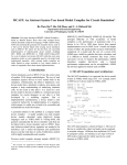
essentially the same circuit, but one that uses a digital input stimulus. Figure 3-1 highlights the
differences between the two designs.
Figure 3-1. Changing circuit from analog-only to mixed-signal
R1
OUT
5k
+
A. Analog only
(Exercise 2)
1.0µ
C1
50
R2
_
R1
B. Analog & Digital
(Exercise 3)
CLK
D2A
OUT
5k
1.0µ
Getting Started with SystemVision™, 4.4
August 2006
C1
50
R2
33
Creating and Simulating a New Design
Exercise 2: Create an Analog Design
These exercises show you how to:
•
Open a new project
•
Create a schematic, using symbols and models from the Educational Library supplied
with SystemVision
•
Place and wire symbols
•
Run a simulation and view results
•
Change the design and resimulate
For basic information on how to use SystemVision™, refer to Chapter 1, “Overview”.
Exercise 2: Create an Analog Design
This exercise shows how to create a new schematic for a design, save it as a project, simulate it,
and view the simulation results.
Open A New Project
1. If you do not have SystemVision running, invoke it as described in Chapter 1,
Overview, “How to Invoke SystemVision”.
2. Select File > New from the menu bar:
This displays the New dialog box.
3. Click the Project tab.
4. In the Name text field, type in a name for this project (such as “exercise2”). The name of
a project must be an alphanumeric string with no spaces.
5. Click the Browse button next to the Location field. This displays the Choose folder
dialog box. Navigate to a directory where you want to store the files and data for this
project. Click Select.
This returns to the New dialog box. Click OK.
Create Schematic
1. To create a new schematic for the circuit in Figure 3-1, select File > New.
a. In the New dialog box, click the File tab.
b. From the Types pane on the right, select Schematic.
c. In the Name text field, type in a name for this schematic (such as “ex2”).
34
Getting Started with SystemVision™, 4.4
August 2006
Creating and Simulating a New Design
Exercise 2: Create an Analog Design
d. Click OK.
This displays a blank schematic in the work area.
2. (Optional) To turn on or off the grid display, select Project > Settings from the main
menu, click the Project tab, enable or disable Grid, and click OK.
Place Symbols
1. Place a voltage source.
a. Select Add > Component from the menu bar.
This displays the Add Component dialog box.
b. Select Electrical > v_pulse.1 > Place , using the indicated Directory, Symbol, and
Button (you can ignore the number associated with the symbol name).
Move the cursor into the schematic. This displays a small symbol for a voltage
source in the schematic. Click to place the symbol.
2. Select and place the remaining symbols. As you did for the voltage source in the
previous step, select component symbols from the Add Component dialog box and place
them in the schematic window.
a. Select Electrical > resistor > Place and place a resistor.
b. Move the cursor back to the Add Component dialog box select Place to place
another resistor symbol (R2).
c. Select Electrical > capacitor > Place and place a capacitor.
d. Select Electrical > electrical_ref > Place and place an electrical ground symbol.
e. Click Close in the Add Component dialog box.
Figure 3-2 shows what the display looks like with the added components.
Getting Started with SystemVision™, 4.4
August 2006
35
Creating and Simulating a New Design
Exercise 2: Create an Analog Design
Figure 3-2. Initial Placement of Symbols
3. Position the symbols.
a. Rotate C1 by right-clicking the symbol to display a popup menu. Select Transform
> Rotate CCW.
which rotates the capacitor symbol 90° counterclockwise.
b. Repeat this rotation action on the symbol for R2.
c. Select each symbol and move it into the positions shown in Figure 3-1.
Wire Symbols
1. After you have moved the symbols into position, you need to connect them.
a. From the menu bar, select Add > Net.
b. Move the cursor to the left end of r1.
c. Click and drag the cursor from r1 to the top connection point of v_pulse1.
This inserts a net between those two symbols, which should follow at a right angle as
you drag.
d. Release the left mouse button. This completes the net between r1 and v_pulse1.
e. Repeat this action to connect the remaining symbols. Figure 3-3 shows how the
completed design should look.
36
Getting Started with SystemVision™, 4.4
August 2006
Creating and Simulating a New Design
Exercise 2: Create an Analog Design
Figure 3-3. Completed Wiring
2. Netlist the design and activate the testbench.
a. Select Simulation > Netlist from the main menu.
If necessary, answer yes to make this the active workbench.
b. In the Design Setup tab of the Testbench Options dialog box, select the following:
Netlisting Option: VHDL
c. Click OK.
Note
If you see messages about wiring errors in the log window, you need to modify the wiring
on your schematic to correct them and then rerun Simulation > Netlist.
3. Save the project. Select File > Save.
Set Properties
1. Set the properties (parameter values) for voltage source v_pulse1.
a. In the schematic work area, right-click the voltage source (v_pulse1). This displays a
popup menu.
b. Select Edit Model Properties, which displays the Model Properties dialog box.
c. Click the Parameters tab. Note that the parameter names for this voltage source are
listed in the left-hand column under Name.
d. In the Value column, enter the following values for each indicated parameter:
Name
Type
WIDTH
TIME
Getting Started with SystemVision™, 4.4
August 2006
Default
Value
1 ms
37
Creating and Simulating a New Design
Exercise 2: Create an Analog Design
Name
Type
Default
Value
PERIOD
TIME
2 ms
PULSE
VOLTAGE
5.0
WIDTH specifies a width of 1 ms for the output pulse.
PERIOD specifies a period of 2 ms for the entire pulse cycle (i.e., 50% duty cycle).
PULSE specifies an amplitude of 5.0 V for the output pulse.
e. Click OK.
2. Set properties (parameter values) for resistors r1 and r2.
a. Right-click r1. Select Edit Model Properties, which displays the Model Properties
dialog box.
b. In the Model Properties dialog box, click the Parameters tab. Find the RES
parameter in the Name column, move your cursor under the Value column, and click
in the blank space. Type 5000 (or 5e3), which specifies 5 kΩ as the resistance for r1.
Name
Type
RES
RESISTANCE
Default
Value
5000
c. Click OK.
d. Right-click r2 and select Edit Model Properties.
e. In the Model Properties dialog box, click the Parameters tab.
f. Find the RES parameter in the Name column, move the cursor under the Value
column, and click in the blank space.
g. Type 50, which specifies 50 Ω as the resistance for r2.
Name
Type
RES
RESISTANCE
Default
Value
50
h. Click OK.
3. Set properties (parameter values) for capacitor c1.
a. Right-click c1 and select Edit Model Properties.
b. In the Model Properties dialog box, click the Parameters tab.
c. Find the CAP parameter in the Name column, move the cursor under the Value
column, and click in the blank space.
38
Getting Started with SystemVision™, 4.4
August 2006
Creating and Simulating a New Design
Exercise 2: Create an Analog Design
d. Type 1e-6, which specifies 1.0µF as the capacitance for c1.
Name
Type
CAP
CAPACITANCE
Default
Value
1e-6
e. Click OK.
4. Set properties for nets.
a. Right-click the net (wire) between v_pulse1 and r1. Select Properties.
b. In the Properties dialog box, click the Name tab.
c. In the Label field, type VIN.
d. Click OK.
e. Right-click the wire between r1 and c1. Select Properties.
f. In the Properties dialog box, click the Name tab.
g. In the Label field, type VOUT.
h. Click OK.
5. Save the schematic. Select File > Save from the main menu.
This saves the schematic in the /sch directory of the Project directory you specified in
Step 5 on page 34.
Compile and Simulate
1. Under TestBenches in the Project Navigator Simulation tab, click the Project that
contains the schematic you created and verify that it is the active testbench (the word
[ACTIVE] should be next to it). If not, right-click and select Set As Active Testbench.
2. (Optional) Compile the design. Select Simulation > Compile > Compile All. The
output log window displays a transcript of the compilation.
Because SystemVision performs all necessary compilation for the active testbench at
simulation, you can choose to skip this step.
3. Select Simulation > Simulate from the menu.
which displays the Simulation Control dialog box (shown in Figure 2-4).
4. In the Simulations tab, make the following selections:
a. Enable: Operating Point and Time-Domain analysis
b. Under Time-Domain Analysis, enter the following value:
End Time: 0.5
Getting Started with SystemVision™, 4.4
August 2006
39
Creating and Simulating a New Design
Exercise 2: Create an Analog Design
5. Click the Results tab, and do the following:
i. Click the arrow for the dropdown list under Time-domain Analysis and select
Selected Waveforms.
ii. Display the list of available waveforms to select by clicking on the browse
button next to this field: ...
iii. In the Waveform List dialog box, click Clear All.
iv. Select the check boxes for the following Waveforms:
V(vin)
r1 - S[i]
V(vout)
r2 - S[v]
v_pulse1 - S[v]
r2 - S[i]
v_pulse1 - S[i]
c1 - S[v]
r1 - S[v]
c1 - S[i]
v. Click OK to close the Waveform List dialog box.
6. To simulate, click OK in the Simulation Control dialog box.
This runs a simulation on the active testbench selected in the Project Navigator. When
the simulation completes, SystemVision launches the waveform analyzer.
View results
Figure 3-4 shows how the waveform analyzer should look when SystemVision finishes
simulation (your display may vary slightly).
40
Getting Started with SystemVision™, 4.4
August 2006
Creating and Simulating a New Design
Exercise 2: Create an Analog Design
Figure 3-4. Waveform Analyzer Display
Waveform
list
1. In the waveform list window, click the [+] indicators next to c1, r1, and r2 to expand the
list of waveform names for each component. Figure 3-5 shows what the waveform list
should look like.
Figure 3-5. Expanded Waveform List
Getting Started with SystemVision™, 4.4
August 2006
41
Creating and Simulating a New Design
Exercise 2: Create an Analog Design
2. Display the following waveforms by double-clicking (or by dragging-and-dropping
them into the waveform display pane; be sure to drag them each below the other).
Under c1: i, v
Under r1: v
Under r2: v
Note that the horizontal display for each waveform is quite compressed—to better view
each waveform, you need to change the range of the X-axis.
You can change the range of the X-axis either by clicking and dragging the mouse
cursor across the time values or by changing X-axis properties, as described in the next
step.
3. Change X-Axis Properties.
a. Move the mouse cursor over the word Time along the X-axis and right-click.
b. In the popup menu, select Properties. This displays the X-Axis Properties dialog
box.
c. Under Axis Range, disable Auto Range. Set Max to 0.005.
d. Click OK.
4. Figure 3-6 shows the four waveforms that should appear in the workspace. Note the
current and voltage values for c1.
Figure 3-6. Pulse Behavior From Analog Source
42
Getting Started with SystemVision™, 4.4
August 2006
Creating and Simulating a New Design
Exercise 3: Create a Mixed-Signal Design
5. Save the waveform database.
a. From the menu bar, select File > Save, which displays the Save Window dialog box
that prompts you for a file name.
b. In the File name field, type src_analog.
c. Click Save.
6. Close all waveform databases.
a. In the Waveform List window, right-click Currently Open Databases.
b. In the Waveform List popup menu, select Close All Databases.
c. In the Confirm dialog box, click Yes.
7. Return to the SystemVision window for Exercise 3.
Exercise 3: Create a Mixed-Signal Design
This exercise shows how to swap out an analog model for an equivalent digital model, resimulate, and view results. Note that this mixed-signal design requires that you insert a special
digital-to-analog interface model.
Create a New Project
1. In the Project Navigator Simulation tab, right-click the active testbench (ex2).
2. Select Remove Testbench from the popup menu. Click Yes in the dialog box that is
displayed.
3. Select File > New from the main menu to display the New dialog box.
4. Click the Project tab.
5. Click the Browse button to navigate to location where you want to store this project.
6. In the Name field, enter a unique name for a new project, such as “exercise3”.
7. Click OK. Click Yes in the dialog box that is displayed (which closes the current project
for Exercise 2).
This changes the displayed project from exercise2 to the Welcome screen.
Getting Started with SystemVision™, 4.4
August 2006
43
Creating and Simulating a New Design
Exercise 3: Create a Mixed-Signal Design
Copy Schematic File
Note
In SystemVision, you cannot copy and paste between schematics that are in different
projects. However, you can copy a schematic file from a project folder in Windows, paste
it to the folder (directory) of a different project, and then open the schematic in that
project.
1. In Windows Explorer, navigate to C:\Mentor_Projects or the folder where you saved the
project for Exercise 2 (the project directory you specified in Step 5 on page 34).
2. Navigate to the exercise2\sch folder.
3. Select the schematic file you created in Exercise 2.
4. From the Explorer menu bar, select Edit > Copy.
5. Navigate to the \sch folder of the project directory for Exercise 3 that you specified in
Step 5, above.
6. Select Edit > Paste.
7. Select the schematic file and rename it to “ex3.1”.
Open New Schematic
1. In the Project Navigator, select the Project tab.
2. Click [+] next to the Design Roots listing. The schematic copied from Exercise 2 should
be listed as “ex3”.
3. Click ex3. This displays the circuit from Exercise 2.
4. Select File > Save.
Replace Analog Source with Digital Source
1. Select the voltage source (v_pulse1).
2. Delete the voltage source. Select Edit > Delete from the main menu (or press the Delete
key).
3. Place a digital clock symbol into the schematic.
a. Select Add > Component from the menu bar.
This displays the Add Component dialog box.
b. Select Digital from the list of directories, select clock.1 from the list of Symbols,
then click Place (you can ignore the number associated with the symbol name).
44
Getting Started with SystemVision™, 4.4
August 2006
Creating and Simulating a New Design
Exercise 3: Create a Mixed-Signal Design
This displays a small symbol for a clock.
Move the cursor to the schematic work area and click to place the symbol.
4. Select the MixedSignal directory in the Add Component dialog box.
5. Select and place a one-bit digital-to-analog symbol (d2a_bit.1).
6. Close the Add Component dialog box.
7. Move the symbols and wires around as needed so you can wire the clock to the d2a and
the d2a to r1. Note that the ground symbol needs to connect only to r2 and c1. Figure 3-7
shows the new design.
Figure 3-7. Mixed-Signal Circuit
Specify Parameter Values
1. Click the d2a_bit symbol and verify its parameter values. This symbol represents an
ideal, one-bit digital-to-analog converter that converts the digital clock signal to an
analog voltage.
a. Right-click the symbol and select Edit Model Properties.
b. In the Model Properties dialog box, note the following parameters and their default
values for analog output.
Name
Type
Default
VHIGH
VOLTAGE
5.0
T_RAMP
REAL
1.0E-9
Getting Started with SystemVision™, 4.4
August 2006
Value
45
Creating and Simulating a New Design
Exercise 3: Create a Mixed-Signal Design
Name
Type
Default
VLOW
VOLTAGE
0.0
Value
c. Click Cancel to use the default values for the d2a_bit converter.
2. Click the clock symbol and specify its parameter values.
a. Right-click the symbol and select Edit Model Properties.
b. In the Model Properties dialog box, note the following clock parameters (the duty
cycle parameter has a default of value of 0.5, or 50%, which emulates the analog
pulse from Exercise 2).
c. Specify a period of 2 ms, as shown.
Name
Type
PERIOD
TIME
DUTY
REAL
Default
Value
2 MS
0.5
d. Click OK.
3. Netlist the design and activate the testbench.
a. Select Simulation > Netlist from the main menu.
If necessary, answer Yes in the confirmation dialog box.
b. In the Testbench Options dialog box, select the following:
Netlisting Option: VHDL
c. Click OK.
Note
If you see messages about wiring errors in the log window, you need to modify the wiring
on your schematic to correct them and then rerun Simulation > Netlist.
4. Save this schematic by choosing File > Save from the menu bar.
Simulate
1. Select Simulation > Simulate from the menu bar.
which displays the Simulation Control dialog box (as shown in Figure 2-4).
2. In the Simulations tab, make the following selections:
a. Enable: Operating Point Analysis, Time-Domain Analysis
46
Getting Started with SystemVision™, 4.4
August 2006
Creating and Simulating a New Design
Exercise 3: Create a Mixed-Signal Design
b. Under Time-Domain Analysis, enter the following value:
End Time: 0.5
3. Click the Results tab, and do the following:
i. Click the arrow for the dropdown list under Time-domain Waveforms and
select Selected Waveforms.
ii. Display the list of available waveforms to select by clicking on the browse
button next to this field: ...
iii. In the Waveform List dialog box, click Clear All.
iv. Select the check boxes for the following waveforms:
r1 - S[v]
r2 - S[v]
r1 - S[i]
r2 - S[i]
d2a_bit1 - S[vout]
c1 - S[v]
d2a_bit1 - S[iout]
c1 - S[i]
v. Click OK to close the Waveform List dialog box.
4. To simulate, click OK in the Simulation Control dialog box.
This runs a simulation on the active testbench selected in the Project Navigator. When
the simulation completes, SystemVision launches the waveform analyzer.
View Results
1. In the Waveform List window of the Waveform Analyzer, click the [+] next to c1, r1,
and r2 to expand the list of waveforms below these components.
2. Display the following waveforms by double-clicking (or by dragging-and-dropping
them into the waveform display pane):
Under c1: i, v
Under r1: v
Under r2: v
Note that the display for each waveform is quite compressed—to better view each
waveform, you need to change the range of the X-axis. You can change the range of the
X-axis either by clicking and dragging the mouse cursor across the time values or by
changing the X-axis properties.
Figure 3-8 shows the four waveforms that should appear in the workspace. Note the
current and voltage values for c1.
3. Save this database.
Getting Started with SystemVision™, 4.4
August 2006
47
Creating and Simulating a New Design
Exercise 3: Create a Mixed-Signal Design
a. From the menu bar, select File > Save, which displays the Save Window dialog box
that prompts you for a file name.
b. In the File name field, type src_digital.
c. Click Save.
4. Close all waveform databases.
a. In the Waveform List window, right-click Currently Open Databases.
b. In the Waveform List popup menu, select Close All Databases.
c. In the Confirm dialog box, click Yes.
Figure 3-8. Pulse Behavior From Digital Clock
48
Getting Started with SystemVision™, 4.4
August 2006
A B C D E F G H I J K L M N O P Q R S T U V W X Y Z
Index
— Symbols —
Experiment, 14
.dproj, 14
.wdb, 14
—F—
—A—
Accuracy, 23
ADVance MS, 7
Attribute, 14
Attribute Editor, 16
—B—
File
as part of project, 15
Frequency domain analysis, 27, 29
Fub (functional block), 14
Functional block, 14
—G—
Block, 13
Block symbols
different from design block, 13
Graph window, 17
Graphical user interface, 15
Grid, 35
Ground symbol, 35
—C—
—H—
Calibration, 23
Case studies, 8
Command line, 16
Compile, 22
how to, 39, 46
Component, 13, 35, 44
Compound waveform, 32
Cursor, waveform, 27
Help, online, 7, 12
Hmax, 23
Hmin, 23
—D—
—L—
Database
DxDesigner, 14
waveform, 14
Design root, 14
Digital-to-analog converter, 45
DxDesigner, 7, 11
—E—
Editor work area, 16
Educational version
limitations, 9
Edulib, 11
Eldo, 7
Eps, 23
Epsilon, 23
Getting Started with SystemVision™, 4.4
August 2006
—I—
Icons, 16
Installation, 13
Invoke SystemVision, 13, 19
Libraries, 11, 14
edulib, 11
SPICE, 12
symbol, 11
Licenses
Educational version, 9
List, 17
—M—
Menu bar, 15
Mouse
right button, 16
Multi-Run, 17
Multi-run simulation, 30
49
A B C D E F G H I J K L M N O P Q R S T U V W X Y Z
—N—
Net, 13
Netlist, 22, 37, 46
Node, 13
—O—
Online help, 7
Operating point analysis
how to run, 25
how to select for simulation, 23, 39, 46
Output Log Window, 22
—P—
Page, 14
Parameter, 14
Parameters
setting values for, 37
sweeping, 30
PCB layout, 10
Pin, 14
Place symbols, 35
Popup menus, 16
Primitive, 13
Project
definition, 14
navigator, 21
new, 34
open, 20
workspace, 16
Project Navigator, 16, 39
Properties, 37
Property, 14
—R—
Related documents, 7
Release Notes, 8
Results
saving, 27, 29
viewing, 26, 28
Root, 14
Rotate, 36
—S—
Save
schematic, 37
Schematic, 14
blank, 35
50
opening in example, 21
Sheet, schematic, 14
Signal list See Waveform list
Signal pane, 17
Simulation, 16
accuracy, 23
running, 39, 46
Simulation Control
dialog box, 16, 17, 22, 27, 39
Small-signal analysis, 27
SPICE, 7, 17
SPICE-on-top, 30
Status bar, 16
Sweep, 30
Symbol, 14
Symbols, 11
placing, 35
wiring, 36
System Designer’s Guide to VHDL-AMS, 8
SystemVision
licensed versions of, 9
website, 8
—T—
Tabs
in Project workspace, 16
Parameters, 37
Results, 24
Simulations, 23, 39, 46
Testbench, 14, 25
Time domain analysis
example, 23, 39, 47
settings, 25
viewing results of, 26
Time step, 23
Toolbar, 16
help on icons, 12
Tree, 17
—U—
UNIX, 10
—V—
Verilog, 10
VHDL-AMS, 7, 19
reference information on, 8
Getting Started with SystemVision™, 4.4
August 2006
A B C D E F G H I J K L M N O P Q R S T U V W X Y Z
—W—
Waveform analyzer
closing, 32
example, 25, 40
initial display, 17
online help, 13
Waveform database, 14
saving, 43, 47
saving results to, 27
Waveform list, 25, 40, 47
example, 26, 27, 28, 41
initial display, 17
Waveforms
compound, 32
listed in waveform viewer, 17
Website, 8
Windows
Start menu item, 13
supported versions, 9
Wire, 14, 36
Wiring a symbol, 36
Work area, 16
—X—
X axis
changing range, 42, 47
—Z—
Zoom, 21
waveform display, 26
Getting Started with SystemVision™, 4.4
August 2006
51
A B C D E F G H I J K L M N O P Q R S T U V W X Y Z
52
Getting Started with SystemVision™, 4.4
August 2006
End-User License Agreement
The latest version of the End-User License Agreement is available on-line at:
www.mentor.com/terms_conditions/enduser.cfm
IMPORTANT INFORMATION
USE OF THIS SOFTWARE IS SUBJECT TO LICENSE RESTRICTIONS. CAREFULLY READ THIS
LICENSE AGREEMENT BEFORE USING THE SOFTWARE. USE OF SOFTWARE INDICATES YOUR
COMPLETE AND UNCONDITIONAL ACCEPTANCE OF THE TERMS AND CONDITIONS SET FORTH
IN THIS AGREEMENT. ANY ADDITIONAL OR DIFFERENT PURCHASE ORDER TERMS AND
CONDITIONS SHALL NOT APPLY.
END-USER LICENSE AGREEMENT (“Agreement”)
This is a legal agreement concerning the use of Software between you, the end user, as an authorized
representative of the company acquiring the license, and Mentor Graphics Corporation and Mentor Graphics
(Ireland) Limited acting directly or through their subsidiaries (collectively “Mentor Graphics”). Except for license
agreements related to the subject matter of this license agreement which are physically signed by you and an
authorized representative of Mentor Graphics, this Agreement and the applicable quotation contain the parties'
entire understanding relating to the subject matter and supersede all prior or contemporaneous agreements. If you
do not agree to these terms and conditions, promptly return or, if received electronically, certify destruction of
Software and all accompanying items within five days after receipt of Software and receive a full refund of any
license fee paid.
1.
GRANT OF LICENSE. The software programs, including any updates, modifications, revisions, copies, documentation
and design data (“Software”), are copyrighted, trade secret and confidential information of Mentor Graphics or its
licensors who maintain exclusive title to all Software and retain all rights not expressly granted by this Agreement.
Mentor Graphics grants to you, subject to payment of appropriate license fees, a nontransferable, nonexclusive license to
use Software solely: (a) in machine-readable, object-code form; (b) for your internal business purposes; (c) for the license
term; and (d) on the computer hardware and at the site authorized by Mentor Graphics. A site is restricted to a one-half
mile (800 meter) radius. Mentor Graphics’ standard policies and programs, which vary depending on Software, license
fees paid or services purchased, apply to the following: (a) relocation of Software; (b) use of Software, which may be
limited, for example, to execution of a single session by a single user on the authorized hardware or for a restricted period
of time (such limitations may be technically implemented through the use of authorization codes or similar devices); and
(c) support services provided, including eligibility to receive telephone support, updates, modifications, and revisions.
2.
EMBEDDED SOFTWARE. If you purchased a license to use embedded software development (“ESD”) Software, if
applicable, Mentor Graphics grants to you a nontransferable, nonexclusive license to reproduce and distribute executable
files created using ESD compilers, including the ESD run-time libraries distributed with ESD C and C++ compiler
Software that are linked into a composite program as an integral part of your compiled computer program, provided that
you distribute these files only in conjunction with your compiled computer program. Mentor Graphics does NOT grant
you any right to duplicate, incorporate or embed copies of Mentor Graphics' real-time operating systems or other
embedded software products into your products or applications without first signing or otherwise agreeing to a separate
agreement with Mentor Graphics for such purpose.
3.
BETA CODE. Software may contain code for experimental testing and evaluation (“Beta Code”), which may not be used
without Mentor Graphics’ explicit authorization. Upon Mentor Graphics’ authorization, Mentor Graphics grants to you a
temporary, nontransferable, nonexclusive license for experimental use to test and evaluate the Beta Code without charge
for a limited period of time specified by Mentor Graphics. This grant and your use of the Beta Code shall not be construed
as marketing or offering to sell a license to the Beta Code, which Mentor Graphics may choose not to release
commercially in any form. If Mentor Graphics authorizes you to use the Beta Code, you agree to evaluate and test the
Beta Code under normal conditions as directed by Mentor Graphics. You will contact Mentor Graphics periodically
during your use of the Beta Code to discuss any malfunctions or suggested improvements. Upon completion of your
evaluation and testing, you will send to Mentor Graphics a written evaluation of the Beta Code, including its strengths,
weaknesses and recommended improvements. You agree that any written evaluations and all inventions, product
improvements, modifications or developments that Mentor Graphics conceived or made during or subsequent to this
Agreement, including those based partly or wholly on your feedback, will be the exclusive property of Mentor Graphics.
Mentor Graphics will have exclusive rights, title and interest in all such property. The provisions of this section 3 shall
survive the termination or expiration of this Agreement.
4.
RESTRICTIONS ON USE. You may copy Software only as reasonably necessary to support the authorized use. Each
copy must include all notices and legends embedded in Software and affixed to its medium and container as received from
Mentor Graphics. All copies shall remain the property of Mentor Graphics or its licensors. You shall maintain a record of
the number and primary location of all copies of Software, including copies merged with other software, and shall make
those records available to Mentor Graphics upon request. You shall not make Software available in any form to any
person other than employees and on-site contractors, excluding Mentor Graphics' competitors, whose job performance
requires access and who are under obligations of confidentiality. You shall take appropriate action to protect the
confidentiality of Software and ensure that any person permitted access to Software does not disclose it or use it except as
permitted by this Agreement. Except as otherwise permitted for purposes of interoperability as specified by applicable
and mandatory local law, you shall not reverse-assemble, reverse-compile, reverse-engineer or in any way derive from
Software any source code. You may not sublicense, assign or otherwise transfer Software, this Agreement or the rights
under it, whether by operation of law or otherwise (“attempted transfer”), without Mentor Graphics’ prior written consent
and payment of Mentor Graphics’ then-current applicable transfer charges. Any attempted transfer without Mentor
Graphics' prior written consent shall be a material breach of this Agreement and may, at Mentor Graphics' option, result in
the immediate termination of the Agreement and licenses granted under this Agreement. The terms of this Agreement,
including without limitation, the licensing and assignment provisions shall be binding upon your successors in interest
and assigns. The provisions of this section 4 shall survive the termination or expiration of this Agreement.
5.
LIMITED WARRANTY.
5.1. Mentor Graphics warrants that during the warranty period Software, when properly installed, will substantially
conform to the functional specifications set forth in the applicable user manual. Mentor Graphics does not warrant
that Software will meet your requirements or that operation of Software will be uninterrupted or error free. The
warranty period is 90 days starting on the 15th day after delivery or upon installation, whichever first occurs. You
must notify Mentor Graphics in writing of any nonconformity within the warranty period. This warranty shall not be
valid if Software has been subject to misuse, unauthorized modification or improper installation. MENTOR
GRAPHICS' ENTIRE LIABILITY AND YOUR EXCLUSIVE REMEDY SHALL BE, AT MENTOR GRAPHICS'
OPTION, EITHER (A) REFUND OF THE PRICE PAID UPON RETURN OF SOFTWARE TO MENTOR
GRAPHICS OR (B) MODIFICATION OR REPLACEMENT OF SOFTWARE THAT DOES NOT MEET THIS
LIMITED WARRANTY, PROVIDED YOU HAVE OTHERWISE COMPLIED WITH THIS AGREEMENT.
MENTOR GRAPHICS MAKES NO WARRANTIES WITH RESPECT TO: (A) SERVICES; (B) SOFTWARE
WHICH IS LICENSED TO YOU FOR A LIMITED TERM OR LICENSED AT NO COST; OR
(C) EXPERIMENTAL BETA CODE; ALL OF WHICH ARE PROVIDED “AS IS.”
5.2. THE WARRANTIES SET FORTH IN THIS SECTION 5 ARE EXCLUSIVE. NEITHER MENTOR GRAPHICS
NOR ITS LICENSORS MAKE ANY OTHER WARRANTIES, EXPRESS, IMPLIED OR STATUTORY, WITH
RESPECT TO SOFTWARE OR OTHER MATERIAL PROVIDED UNDER THIS AGREEMENT. MENTOR
GRAPHICS AND ITS LICENSORS SPECIFICALLY DISCLAIM ALL IMPLIED WARRANTIES OF
MERCHANTABILITY AND FITNESS FOR A PARTICULAR PURPOSE AND NON-INFRINGEMENT OF
INTELLECTUAL PROPERTY.
6.
LIMITATION OF LIABILITY. EXCEPT WHERE THIS EXCLUSION OR RESTRICTION OF LIABILITY
WOULD BE VOID OR INEFFECTIVE UNDER APPLICABLE LAW, IN NO EVENT SHALL MENTOR GRAPHICS
OR ITS LICENSORS BE LIABLE FOR INDIRECT, SPECIAL, INCIDENTAL, OR CONSEQUENTIAL DAMAGES
(INCLUDING LOST PROFITS OR SAVINGS) WHETHER BASED ON CONTRACT, TORT OR ANY OTHER
LEGAL THEORY, EVEN IF MENTOR GRAPHICS OR ITS LICENSORS HAVE BEEN ADVISED OF THE
POSSIBILITY OF SUCH DAMAGES. IN NO EVENT SHALL MENTOR GRAPHICS' OR ITS LICENSORS'
LIABILITY UNDER THIS AGREEMENT EXCEED THE AMOUNT PAID BY YOU FOR THE SOFTWARE OR
SERVICE GIVING RISE TO THE CLAIM. IN THE CASE WHERE NO AMOUNT WAS PAID, MENTOR
GRAPHICS AND ITS LICENSORS SHALL HAVE NO LIABILITY FOR ANY DAMAGES WHATSOEVER. THE
PROVISIONS OF THIS SECTION 6 SHALL SURVIVE THE EXPIRATION OR TERMINATION OF THIS
AGREEMENT.
7.
LIFE ENDANGERING ACTIVITIES. NEITHER MENTOR GRAPHICS NOR ITS LICENSORS SHALL BE
LIABLE FOR ANY DAMAGES RESULTING FROM OR IN CONNECTION WITH THE USE OF SOFTWARE IN
ANY APPLICATION WHERE THE FAILURE OR INACCURACY OF THE SOFTWARE MIGHT RESULT IN
DEATH OR PERSONAL INJURY. THE PROVISIONS OF THIS SECTION 7 SHALL SURVIVE THE
EXPIRATION OR TERMINATION OF THIS AGREEMENT.
8.
INDEMNIFICATION. YOU AGREE TO INDEMNIFY AND HOLD HARMLESS MENTOR GRAPHICS AND ITS
LICENSORS FROM ANY CLAIMS, LOSS, COST, DAMAGE, EXPENSE, OR LIABILITY, INCLUDING
ATTORNEYS' FEES, ARISING OUT OF OR IN CONNECTION WITH YOUR USE OF SOFTWARE AS
DESCRIBED IN SECTION 7. THE PROVISIONS OF THIS SECTION 8 SHALL SURVIVE THE EXPIRATION OR
TERMINATION OF THIS AGREEMENT.
9.
INFRINGEMENT.
9.1. Mentor Graphics will defend or settle, at its option and expense, any action brought against you alleging that
Software infringes a patent or copyright or misappropriates a trade secret in the United States, Canada, Japan, or
member state of the European Patent Office. Mentor Graphics will pay any costs and damages finally awarded
against you that are attributable to the infringement action. You understand and agree that as conditions to Mentor
Graphics' obligations under this section you must: (a) notify Mentor Graphics promptly in writing of the action;
(b) provide Mentor Graphics all reasonable information and assistance to defend or settle the action; and (c) grant
Mentor Graphics sole authority and control of the defense or settlement of the action.
9.2. If an infringement claim is made, Mentor Graphics may, at its option and expense: (a) replace or modify Software so
that it becomes noninfringing; (b) procure for you the right to continue using Software; or (c) require the return of
Software and refund to you any license fee paid, less a reasonable allowance for use.
9.3. Mentor Graphics has no liability to you if infringement is based upon: (a) the combination of Software with any
product not furnished by Mentor Graphics; (b) the modification of Software other than by Mentor Graphics; (c) the
use of other than a current unaltered release of Software; (d) the use of Software as part of an infringing process; (e) a
product that you make, use or sell; (f) any Beta Code contained in Software; (g) any Software provided by Mentor
Graphics’ licensors who do not provide such indemnification to Mentor Graphics’ customers; or (h) infringement by
you that is deemed willful. In the case of (h) you shall reimburse Mentor Graphics for its attorney fees and other costs
related to the action upon a final judgment.
9.4. THIS SECTION IS SUBJECT TO SECTION 6 ABOVE AND STATES THE ENTIRE LIABILITY OF MENTOR
GRAPHICS AND ITS LICENSORS AND YOUR SOLE AND EXCLUSIVE REMEDY WITH RESPECT TO
ANY ALLEGED PATENT OR COPYRIGHT INFRINGEMENT OR TRADE SECRET MISAPPROPRIATION
BY ANY SOFTWARE LICENSED UNDER THIS AGREEMENT.
10. TERM. This Agreement remains effective until expiration or termination. This Agreement will immediately terminate
upon notice if you exceed the scope of license granted or otherwise fail to comply with the provisions of Sections 1, 2, or
4. For any other material breach under this Agreement, Mentor Graphics may terminate this Agreement upon 30 days
written notice if you are in material breach and fail to cure such breach within the 30 day notice period. If Software was
provided for limited term use, this Agreement will automatically expire at the end of the authorized term. Upon any
termination or expiration, you agree to cease all use of Software and return it to Mentor Graphics or certify deletion and
destruction of Software, including all copies, to Mentor Graphics’ reasonable satisfaction.
11. EXPORT. Software is subject to regulation by local laws and United States government agencies, which prohibit export
or diversion of certain products, information about the products, and direct products of the products to certain countries
and certain persons. You agree that you will not export any Software or direct product of Software in any manner without
first obtaining all necessary approval from appropriate local and United States government agencies.
12. RESTRICTED RIGHTS NOTICE. Software was developed entirely at private expense and is commercial computer
software provided with RESTRICTED RIGHTS. Use, duplication or disclosure by the U.S. Government or a U.S.
Government subcontractor is subject to the restrictions set forth in the license agreement under which Software was
obtained pursuant to DFARS 227.7202-3(a) or as set forth in subparagraphs (c)(1) and (2) of the Commercial Computer
Software - Restricted Rights clause at FAR 52.227-19, as applicable. Contractor/manufacturer is Mentor Graphics
Corporation, 8005 SW Boeckman Road, Wilsonville, Oregon 97070-7777 USA.
13. THIRD PARTY BENEFICIARY. For any Software under this Agreement licensed by Mentor Graphics from Microsoft
or other licensors, Microsoft or the applicable licensor is a third party beneficiary of this Agreement with the right to
enforce the obligations set forth herein.
14. AUDIT RIGHTS. You will monitor access to, location and use of Software. With reasonable prior notice and during
your normal business hours, Mentor Graphics shall have the right to review your software monitoring system and
reasonably relevant records to confirm your compliance with the terms of this Agreement, an addendum to this
Agreement or U.S. or other local export laws. Such review may include FLEXlm or FLEXnet report log files that you
shall capture and provide at Mentor Graphics’ request. Mentor Graphics shall treat as confidential information all of your
information gained as a result of any request or review and shall only use or disclose such information as required by law
or to enforce its rights under this Agreement or addendum to this Agreement. The provisions of this section 14 shall
survive the expiration or termination of this Agreement.
15. CONTROLLING LAW, JURISDICTION AND DISPUTE RESOLUTION. THIS AGREEMENT SHALL BE
GOVERNED BY AND CONSTRUED UNDER THE LAWS OF THE STATE OF OREGON, USA, IF YOU ARE
LOCATED IN NORTH OR SOUTH AMERICA, AND THE LAWS OF IRELAND IF YOU ARE LOCATED
OUTSIDE OF NORTH OR SOUTH AMERICA. All disputes arising out of or in relation to this Agreement shall be
submitted to the exclusive jurisdiction of Portland, Oregon when the laws of Oregon apply, or Dublin, Ireland when the
laws of Ireland apply. Notwithstanding the foregoing, all disputes in Asia (except for Japan) arising out of or in relation to
this Agreement shall be resolved by arbitration in Singapore before a single arbitrator to be appointed by the Chairman of
the Singapore International Arbitration Centre (“SIAC”) to be conducted in the English language, in accordance with the
Arbitration Rules of the SIAC in effect at the time of the dispute, which rules are deemed to be incorporated by reference
in this section 15. This section shall not restrict Mentor Graphics’ right to bring an action against you in the jurisdiction
where your place of business is located. The United Nations Convention on Contracts for the International Sale of Goods
does not apply to this Agreement.
16. SEVERABILITY. If any provision of this Agreement is held by a court of competent jurisdiction to be void, invalid,
unenforceable or illegal, such provision shall be severed from this Agreement and the remaining provisions will remain in
full force and effect.
17. PAYMENT TERMS AND MISCELLANEOUS. You will pay amounts invoiced, in the currency specified on the
applicable invoice, within 30 days from the date of such invoice. Any past due invoices will be subject to the imposition
of interest charges in the amount of one and one-half percent per month or the applicable legal rate currently in effect,
whichever is lower. Some Software may contain code distributed under a third party license agreement that may provide
additional rights to you. Please see the applicable Software documentation for details. This Agreement may only be
modified in writing by authorized representatives of the parties. Waiver of terms or excuse of breach must be in writing
and shall not constitute subsequent consent, waiver or excuse.
Rev. 060210, Part No. 227900