1
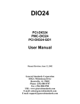
WSC-5-DDOR Wind Speed Controller
Dual Set Point
User’s Manual
Texas Electronics, Inc.
Dallas, TX 75235
5529 Redfield Street
Tel.214.631.2490
Fax.214.631.4218
www.texaselectronics.com
Model WSC-5-DDOR Wind Speed Controller Dual Set Point
DESCRIPTION
The Texas Electronics, Inc. WSC-5 wind speed activated control system is designed for switching on or off, various types of equipment such as deodorizers, samplers, alarms, fountains, beacons, etc. when the wind speed
exceeds or falls below a certain selectable value. The control output function (either switch-on or switch-off,
or both) can be set for activation at any desired wind speed value from 0 to 100 mph. Single and dual set point
WSC-5 systems are available depending upon the requirements of the user. An adjustable time delay is used
to minimize premature on/off cycling of the equipment being controlled when the wind speed is fluctuating
around the selected set point. The time delays are programmable with time periods ranging from 1 to 1023
seconds. To set the time delay, turn on the dip switches to combine for the total time of the delay. For example, to have a 5 minute (300 second) delay, the 256, 32, 8, and 4 switches would be turned on while the 512,
128, 64, 16, 2, and 1 switches would be off. 256 + 32 + 8 + 4 = 300. If a delay on make or break is undesired,
then the 1 switch for that function would be turned on and all other switches for that function turned off. IF
ALL SWITCHES FOR A FUNCTION ARE TURNED OFF, THE FUNCTION WILL NOT OPERATE.
The set points are adjustable by knobs located on front of the meter relay. Two modes of operation are provided: automatic and latching. In the automatic mode, the relays are energized at wind speeds exceeding the set
points, but automatically de-energizes when the wind speed falls below the set points. In the latching mode,
the relays energizes when the wind speed set points are exceeded and remains energized until manually reset.
The WSC-5 indicator/control components are housed in a weather-tight enclosure for maximum environmental protection. Conduit connectors are mounted on the cabinet base for entry of respective cables. A large
terminal strip is provided within the enclosure for making the appropriate cable connections.
SPECIFICATIONS:
Controller-Indicator Console, Series WSC-5
Indicator range, wind speed:
0 to 100 mph
Indication/actuation accuracy:
±2% of full scale
Set point adjustability:
Adj. over full scale
Dual set point units:
Adj. to within 0 mph of each other
Relay contact ratings:
10 amps, 115 VAC resistive
Single set point output:SPDT
Double set point output:
SPDT (two)
Time delay for each set point:Adjustable,
Standard:adjustable from 1 to 1023 seconds
Operator controls:1)
on-off switch
2)
latch-automatic mode switch
3)
set point adjustment knob(s)
4)
time delay set point dip switches
Control console size:
11.86"W x 14.97"H x 7.38"D
Enclosure type:NEMA 3,3R, 4,4X AND12
Mounting:Wall type
Finish:Gray Fiberglass Inside/Out
Temperature Range (control units):
-20°F to +165°F
Excitation requirements:
105-130 VAC, 60 Hz.
Power consumption:Approx. 3 watts
Wind Speed Sensor, Model TV-114
Starting speed:Nominally 2.0/2.5 mph
Signal output:Nominally 4.7, VAC@100MPH
Excitation requirements:Self-generating
Dimensions:18" diameter x 12" high
Finish:Gold anodized aluminum
Connection cable (std):
60’, 18 Gauge 2 conductor
Lubrication:None
THEORY OF OPERATION:
The WSC-5 wind speed indicator and control circuit consists of a specially designed optical panel meter relay and
related accessories. The unit combines a moving coil meter with a non-contacting, adjustable photo-electric sensor,
switching circuit and output switch(s). A vane on the meter moving coil breaks a beam of light as the indicating
pointer passes the wind speed set point reference pointer. The photo-transistor switches an electronic circuit that
energizes or de-energizes the output relay(s) contacts which in turn operate, either "ON" or "OFF", the controlled
equipment. The wind speed set pointer(s) is driven directly with an adjustable knob(s) which can be set to any desired wind speed reference value.
When the wind speed sensor generated voltage signal exceeds the set pointer speed reference value, the electronic
switching circuit energizes or de-energizes the output relay, depending upon initial installation. The AUTO-LATCH
switch on the console is provided so that when it is in the AUTO position, the operation of the equipment will be
"ON" or "OFF" as the wind speed falls above or below the pre-set value. In the LATCH position, ground path is provided, which holds the relay(s) closed once the speed reference level is exceeded. Relay contacts will remain in this
position regardless of the input signal until the AUTO-LATCH is switched back to AUTO.
Model NumberSystem Description
WSC-5-SDOR
Single set point, delay on operate and release.
WSC-5-DDOR
Double set point, delay on operate and release.
Wind speed is measured by a 3-cup anemometer which is remotely located from the wind speed control/indicator
assembly. the rotating cup assembly is directly connected to a precision low-torque alternating current generator.
The absence of brushes and contacts in this generator provide for long life and relatively low sensor starting threshold. The life of the generator is essentially equal to the life of its bearings. bearings are incorporated on both the
anemometer and generator shafts which require no additional lubrication. All exposed parts are constructed of
gold anodized aluminum to resist adverse environmental conditions. A plastic insulated two-conductor shielded 18
gauge cable is provided for single transmission from sensor to indicator/controller (60 feet normally supplied).
OPERATING INSTRUCTIONS:
A. INSTALLATION:
Console and wind speed sensor may be mounted at any desired location. The speed sensor should be mounted so that it will
measure a true representative sample of the wind speed. It should be mounted high enough to clear all obstructions in a vertical position. The mount tube supplied with the transmitter may be clamped to any convenient vertical mast as desired. the
indicator/controller may be mounted either indoors or outside as required.
CABLE CONNECTIONS
ALL OUTPUT RELAY CONTACTS ARE RATED 10 AMPS @ 30 VDC OR 277 VAC RESISTIVE; 1/2 HP @ 250 VAC; 1/3
HP @ 120 VAC
NC
Normally Closed
C
Common
NO
Normally Open
PRIMARY POWER:
HI
Black, Hot
LO
White, Neutral
G
Green, Ground
METER OUTPUT: 0-1 VOLT
WH
White, Positive
BL
Black, Negative
This output is load sensitive and must maintain its 1000 ohm calibrated load. If a remote indicator is added it must be 0-1
Ma. with an internal resistance of 1000 ohms. When the proper meter is added the 1000 ohm resistor must be removed. If
a high impedance device is used (100K and up) such as a Computer Interface, PLC, Data Logger or DPM is used leave the
1000 ohm resistor in place.
TWO BLANK TERMINALS:
There are no connections to these. The customer may use them as “Tie Points” for external wiring if needed.
SPEED SENSOR:
Because the sensor is an AC generator polarity is not critical. If any stray pickup is experienced the shield (Bare Wire) from
the sensor should be attached to panel ground. The panel mounting screw at the bottom right nearest the sensor terminals.
WSC-5-SDOR or DDOR
The wiring for the double set point is the same as the single except one more set of Form
"C" Contacts have been added. One is marked "LO Output Relay" and one is marked "HI
Output Relay". Both sets are Form "C" Dry Contacts. (No Voltage Present)
B. OPERATION:
After making all necessary connections, adjust the wind speed set pointer(s) on the front meter face to the desired wind
speed alarm/control value(s) . Select either Automatic or Latch mode of operation. Adjust the time delay(s) as desired. The
WSC-5 is now ready to use. Apply power to the system by turning on the INPUT power supply.
The controller is now operating. The wind speed will be directly indicated by the meter. When the control setting is exceeded and the CONTROL OUTPUT circuit is switched, the CONTROL OUTPUT light(s) will come on.
CHECKOUT AND MAINTENANCE:
A portable wind speed test apparatus (Model T-8011) is available from the manufacturer for checking the
electrical output of the wind speed sensor. T-8011 will drive the wind speed sensor at a know RPM which
is equal to a specific speed value. At the specified RPM the wind speed indicator should indicate that speed
value within ±l mph. The test unit, if desired, may be purchased, or it may be obtained on a loan basis
from the manufacturer.
PROPER EXPOSURE OF METEOROLOGICAL INSTRUMENTS
Generally recognized guidelines follow which depict "ideal" sensor mounting locations. These guidelines or
"rules of thumb" are only suggestive in nature in an attempt to aid the user to selecting optimum representative
sampling locations for a particular sensor.
Reference was made to US Weather Bureau Installation criteria in preparing this data (See Reference 1).
WIND EQUIPMENT:
So far as available sites permit, wind sensors should be placed above the ground on a freely-exposed tower (20
feet or higher) and over terrain that is relatively level and free from obstructions to wind flow. When a compromise must be made, sensing units should be exposed at least 12 feet above any obstruction within 100 feet
and at least as high as any obstruction within 100 to 200 feet of the wind equipment. Support towers or masts
should not be of such bulk or shape as to create an appreciable obstruction to wind flow. Avoid sites where local
obstructions may create up-or-down drafts, eddy currents or jet-flow effects. When sensors are roof-mounted,
they should be installed at least 10 feet (or greater) from the roof surface depending upon the particular installation site. Turbulence and other local effects can be reduced somewhat by mounting sensors on the upwind
and of the building (that end of the building exposed to the most common local prevailing winds). Horizontal-mount booms which extend from existing towers should be fabricated so that sensors will extend a distance
of 5 to 10 feet from the tower assembly (dependent on tower thickness).
Wind direction sensors are oriented upon installation in reference to either true north or magnetic north. True
north is obtained by applying a local magnetic variation correction factor to a magnetic north compass indication (magnetic variation for a particular locality is obtainable from the nearest Weather Bureau Branch Office).
Indicator readings for a true north sensor orientation will then be in terms of true geographic compass points.
All U.S. Weather Bureau surface wind data used for observational network reporting purposes and general public use is given in reference to this true north format. Indicator readings for a magnetic north sensor orientation
will be in terms of actual readings as would be obtained from directly viewing a magnetic compass instrument.
Wind direction data at Federal Aviation Agency and other aircraft reporting facilities (for direct control tower-to-pilot utilization) is always made in reference to this magnetic north format.
REMOTE TEMPERATURE/HUMIDITY SENSORS AND INSTRUMENT SHELTERS:
Whenever possible, instrument shelters* as well as remote temperature and/or humidity sensors should be
installed at a height of 4 feet (or greater) over earth or sod at least 100 feet from any concrete or other hard-surfaced area and not closer to any other object than four times the height of the object above the instrument shelter or remote sensors. Avoid roof installations if possible. If it is necessary to roof-mount shelters and sensors,
they should not be closer than 30 feet to any large, vertical reflecting surface (walls, etc.), exhaust fans, or cooling towers. Electronic remote sensors when roof-mounted should be at least 9 feet (or greater) above the roof
surface. To minimize radiation effects from the roof, they can also be mounted on a horizontal boom so that
they will extend from the side of a building roof or existing tower. Horizontal booms should extend approximately 5 to 10 feet from the side of the building roof or tower assembly.
PRECIPITATION GAUGES:
Rain gauges should be installed on a level plot of ground, at a distance from any object of at least two and preferably four times the height of the object above the top of the gauge. All types of gauges must be exposed with the
rim of the receiver in a horizontal plane and at a level well above the average level of snow surfaces.
* Standard U.S. Weather Bureau cotton-region shelter (Spec. No. 450.0615, Rev. 8/67)
Roof-mounting of rain gauges should be avoided when possible. Air currents at heights other than at ground level have
been observed to cause an apparent decrease in rainfall catch commensurate with the increase in mounting height above
ground level.
Objects which individually or in small groups constitute a "windbreak" reduce prevailing wind speed in the vicinity
of the gauge. This reduction of wind speed will, as a consequence, also reduce possible eddy currents and turbulence
around the gauge. The presence of such objects is usually beneficial in providing a more accurate rainfall catch. Ideally,
the "windbreak" objects (fences, bushes, etc.) should be generally uniform in height and distance from the gauge. Height
above the gauge should not exceed about twice their distance from the gauge.
ANEROID BAROMETERS - SELF-CONTAINED MECHANICAL INSTRUMENTS AND ELECTRONIC REMOTE BAROMETRIC PRESSURE SENSORS:
Select a site where the instrument will not be subject to rapid fluctuations of temperature or to jarring and continuous
vibration. Avoid exposing the instrument to direct sunlight or radiant heaters and to direct drafts such as open windows
and doors.
Reference 1:
U.S. Department of Commerce - National Weather Service Bulletin
LS 5927 Revised, 0-4.12, January, 1963.
SOLAR RADIATION SENSORS:
The Solar Radiation Sensor is normally mounted on a level surface totally remote from trees, poles, or power lines that
might cast a shadow on the sensor at any time of the day. However, there may be occasions, because of extreme latitudes, when it is desired to mount the sensor at some angle other than level.
The sensors may also be mounted on a sun tracking mechanism or behind a shadow band if diffuse sky radiation is to be
measured.
WIND DIRECTION & SPEED SENSORS
INSTALLATION
These instructions apply to roof-top installation. We advise that you first read over these instructions before beginning
assembly as several referenced items are not supplied with your weather equipment (this is because most every installation is unique thus these parts are best obtained by the installer). Reference to the “U-Tube Cross-Bar Installation”
figure and “.Sensor Installation” figure may be helpful.
Step 1:Attach the three anemometer cups to the speed sensor head.
Loosen the three set screws on the top of the anemometer (lower unit).
Insert the anemometer cup arms into the holes. Be sure to press the arms all the way in and make sure that the flat areas
on the arms face toward the set screws.
Tighten the set screws.
Step 2:Attach wind vane and counter-weight to the direction sensor head.
Loosen the two set screws on the top of the wind vane (upper unit).
Insert the vane and counter-weight into the holes. Be sure to press both parts all the way in and make sure the flat
areas on each arm face the set-screws.
Tighten the set screws.
Note: For optimum performance and maximum bearing longevity you may wish to fine-tune the balance of both
wind sensors. Place the U-tube flat on a table such that the sensors hang over the edge. Rotate the vane and the
cup in 10 degree increments. After positioning the vane and cups verify that there is no movement after releasing
your hold (this must be done in a wind-free environment). Balance adjustments are made by loosening the set
screw to the lighter cup, counter-weight or fin and shifting it slightly away from the sensor head.
Step 3:Attach cross-bar to U-tube.
Spread end clamps and slide over the U-tube.
Insert cross-bar into the ends of both clamps.
Fasten cross-bar in a level position with screws, nuts and washers.
Step 4:Attach U-bolts to cross-bar and U-tube.
Remove the two nuts and reinforcing plate from both U-bolts (do not remove the toothed bracket).
Insert one U-bolt through the two holes in the cross-bar and the other through the two holes in the bottom of the
U-arm (be careful not to damage the wires inside the U-arm).
Replace the tube reinforcing plate on the U-bolt and replace the U-bolt nuts.
Step 5:Slip the U-bolts over the mast and tighten.
Make certain that the anemometer cups do not hit the mast.
Step 6:Attach guy wire clamp just below the U-tube assembly.
Step 7:Attach base mount to the roof or side wall.
Note that the base mount U-bolt will rotate to fit any angle.
Step 8:Install guy wire anchors (not included) or locate secure points for guy wire attachment.
Step 9:Erect mast and install guy wires (not included) and turn-buckles (not-included).
Step 10: Ground the mast to help protect the sensors and structure from lightning hits.
Supplies needed: mast wire clamp, grounding wire, wire supports and grounding rod.
Step 11: Run the sensor wire inside to the console.
Lead in wire is permanently attached to the sensor unit.
Attach to console according to wire color code.
If necessary the cable may be cut down in length or wire may be added with negligible effect on the calibration. If
changing cable lengths more than a few hundred feet you may wish contact the factory to determine the severity
of the effect on calibration.
Additional cable lengths are available from Texas Electronics if needed.
Step 12: Calibrate the Wind Vane.
Be sure console is operating properly first.
This is normally a two man job with one individual watching the direction indicated by the weather station and
the other adjusting the sensor while watching a compass.
Two methods of aligning the vane are available. The first method involves loosening the large set screw at the
bottom of the wind direction sensor so that it will rotate on the U-arm. Turn the bottom half of the sensor until
the compass readings and the indication match then retighten the set screw. The second method involves rotating the entire mast assembly until proper orientation is achieved; this technique is usually easier because of the
heights involved but will usually necessitate repositioning (rotating) of the guy-wire clamp.
If winds are creating rapid fluctuations in the vane making calibration difficult, the vane can be temporarily secured in a fixed position by carefully wedging a thickly folded piece of paper or cardboard into the gap between
the upper and lower halves of the direction sensor. An alternative technique is to lap a string over the vane and
carefully hold it in position (be careful not to bend the vane when using this approach).
MODEL TV-114 WIND SPEED SENSOR
DESCRIPTION:
Long term maintenance-free operation is characteristic of this sensor. A precision alternating
current generator is employed which completely eliminates contact between rotating and stationary
generator components.
The Texas Electronics TV-114 Wind Speed Sensor consists of a lightweight three-cup anemometer
which is mechanically coupled to a precision alternating current generator located within the lower
sensor housing.
The output signal from the sensor is an alternating current signal whose amplitude and frequency
are proportional to wind speed.
Exposed components are constructed of gold anodized aluminum to retard corrosion even in the
extremes of heat, cold, and salt water environment. Sensors are designed to be as sensitive as possible to light winds yet strong enough to withstand winds of hurricane force.
The TV-114 uses the TE-505 bearing system which was developed by Texas Electronics exclusively
for use with meteorological sensors. This system has two stainless-steel bearings mounted in a pre-
SPECIFICATIONS:
Signal Conditioning:
Signal conditioning circuits are available which can convert the raw sensor signal into a scaled voltage or current. This analog signal can then be fed to indica
tors, recorders, computers, etc.
Starting Threshold:
Approx. 2.5 to 3.0 mph
Accuracy (frequency output):
±2 mph
Excitation Requirements:
None (self generating)
Distance Constant:21.7 feet
Generator Type:
16” pole AC, brushless
Bearing Grade:
APEC 3 or better
Cable:60’, 18 Gauge 2 conductor
Environment Limits:
Temperature:-50ºC to +75ºC
Humidity:0-100%
Physical:
Cup Diameter:4"
Cup Wheel Diameter:18"
Overall Height:7½"
Outer Finish:Gold anodized aluminum
Weight:3.75 pounds (with cable)
Maintenance:
Possible bearing and generator replacement at three to ten
year intervals (dependent upon environmental conditions).
Calibration:
Field testing and recalibration is performed by attaching a
motor (TE part number T-8011) to the sensor which spins
the head at a known RPM.
Warranty:3 years
Optional:4-20 mA output
Wiring:12-15 VDCRed Wire
CommonBlack Wire
4-20 mA SignalWhite Wire
TV-114 WIND SENSOR
G-114 GENERATOR
The chart below shows the maximum output obtainable from this generator, under a no load condition. This signal may be scaled down to fit many customer requirements.
R.P.M. VS. OUTPUT
RPM
MPH
KNOTS
G-114 AC Generator G-114 AC Generator
AC VOLTS
DC VOLTS
0
0
0.000
0.00
0.0
50
5
4.345
0.22
0.35
100
10
8.684
0.45
0.78
200
20
17.368
0.95
1.65
300
30
26.052
1.43
2.38
400
40
34.736
1.92
3.12
500
50
43.420
2.38
3.83
600
60
52.104
2.86
4.60
700
70
60.788
3.32
5.35
800
80
69.472
3.79
6.11
900
90
78.156
4.25
6.90
1000
100
86.840
4.70
7.65
Warranty
Texas Electronics, Inc. (hereafter TEI) warrants the equipment manufactured by it to be free from defects in
material and workmanship. Upon return, transportation charges prepaid to TEI, within three (3) years of original shipment of sensors and one (1) year of original shipment of electronics, recorders and indicators, TEI will
repair or replace, at its option, any equipment which it determines to contain defective material or workmanship, and will return said equipment to purchaser, F.O.B., TEI. Texas Electronics shall not be obligated however to repair or replace equipment which has been repaired by others, abused, improperly installed, altered
or otherwise misused or damaged in any way. TEI will not be responsible for any dismantling, re-assembly, or
reinstallation charges.
This warranty is in lieu of all other warranties, expressed or implied. TEI shall not be liable for any special,
indirect, incidental or consequential damages claimed in connection with any rescission of this agreement by
purchaser.
For a list of specific items covered by the extended warranty, see the Three-Year Warranty Equipment List.
Three-Year Warranty Equipment List
Effective February 1, 1992 all of Texas Electronics, Inc. sensors will carry a Three-Year warranty instead of the
previous One-Year. The remainder of terms and conditions of the warranty remains unchanged. A specific list
of items follows.
Sensors Covered by Three-Year Warranty
Wind Direction
Parameter
TD-104-5D
TD-106-5D
Wind Speed
TV-114
TV-110-L320
TV-4
Barometric Pressure
Rainfall
TB-2012M
TR-525
Temperature
TT-101-QR
TH-2013-QR
TT-103-R-W
TTH-1315
Solar Radiation
SP-LITE
Model #
Systems Covered by Three-Year Warranty
WSC-5-SDOR
WSC-5-DDOR
Model #
Description
Wind Speed Controller, Single Set Point
Wind Speed Controller, Dual Set Point