1
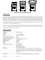
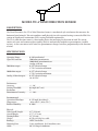
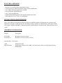
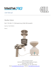
Complete Weather Station
User’s Manual
Texas Electronics, Inc.
Dallas, TX 75235
Fax.214.631.4218
5529 Redfield Street
Tel.214.631.2490
www.texaselectronics.com
Model TR-525 Rainfall Sensors
DESCRIPTION
The sensor consists of a gold anodized aluminum collector funnel with a knife-edge that diverts the water to a tipping bucket mechanism. The models TR-525I and TR-525USW are calibrated in inches (.01” per tip) and model
TR-525M is calibrated in millimeters (.1mm per tip). A magnet is attached to the tipping bucket, which, as the
bucket tips, actuates a magnetic switch. Thus, a momentary switch closure takes place with each tip of the bucket.
Connecting the sensor to an event counter on an electronic datalogger or display module will allow record keeping of accumulated rainfall. If an analog signal representing rainfall accumulation is required, Texas Electronics,
Inc. manufactures a suitable conditioning circuit.
The spent water drains out of the bottom of the housing; hence, the sensor requires no attention or servicing of
any sort. It is completely automatic. The aluminum sensor housing is finished with a white baked enamel paint to
withstand years of exposure to the environment.
SPECIFICATIONS
Resolution:
0.01” or 0.1 mm
Accuracy:
English
1.0% at 1”/hr or less
Metric
1.0% at 10 mm/hr or less
Average Switch Closure Time:
135 ms
Maximum Bounce Settling Time: 0.75 ms
Maximum Switch Rating:
30 VDC @ 2 A, 115 VAC @ 1 A
Temperature Limits:
+32°F to +125°F
Humidity Limits:
0 to 100%
Height:10.125”
Weight:2.5 pounds
Receiving Orifice Diameter:
6.060” (English)
9.664” (Metric)
8.000” USW (English)
Cable:
25’, 24 Gauge 2 conductor
Installation:
Consists of attaching the three sensor support legs to a firm platform or securing the side bracket to a stable vertical structure such as the lower end of weather station mast. Sensor cable is then connected to monitoring equipment.
Maintenance:
Occasional cleaning of debris from filter screen may be required.
Warranty:3 years
ORDERING INFORMATION
Model # Description
TR-525I TR-525USW TR-525M Rain Gauge, 6.06” collector, English
(Please specify for calibration of 0.2 mm/tip)
Rain Gauge, 8.00” collector, English
Rain Gauge, 25 mm collector, Metric
Optional Parts / Accessories
HOBO
MB-525
FC-525
BB-525
HT-525
Cable
Event Datalogger and Software
Pole Mounting Base
Field Calibration Kit
Bird Repellant
Heater, 120 VAC
Additional Cable
MODEL 525
TIPPING BUCKET RAIN GAUGE TRANSMITTER
INSTALLATION INSTRUCTIONS
A clear and unobstructed mounting location is necessary to obtain accurate rainfall readings.
This transmitter has provisions for mounting two ways, surface mounting and mast mounting. Surface mounting is recommended where possible. The transmitter housing MUST be mounted in a LEVEL position and in
a location free from vibration. If mast mounted, make sure that the mast is properly guyed so that vibration in
high winds is kept to a minimum.
THE FOLLOWING IS VERY IMPORTANT:
After the final transmitter installation has been made, remove the top gold funnel portion of the transmitter and
observe the black tipping bucket. It should NOT (repeat NOT) be held in a dead center position by the magnetic attraction of the bucket magnet and the hermetically sealed magnetic switch. Press either end of the bucket
down against the stop to be sure that it is not centered.
The transmitter to indicator connecting cable may be either shortened or lengthened as required.
The funnel and tipping bucket mechanism should be cleaned periodically. An accumulation of dirt, bugs, etc.
on the tipping bucket will adversely affect the calibration.
FIELD CALIBRATION
TR-525USW
Absolutely accurate calibration can be obtained only with laboratory equipment, but an approximate field check
can be easily made. The tipping bucket mechanism is a simple and highly reliable device. The transmitter must
be located in a clear area, away from trees, buildings, etc. It must also be mounted level. Accurate readings
will not be obtained unless the transmitter is mounted in a level position. The mechanism must be clean. Any
accumulation of foreign material, dust, etc. will alter the calibration of this unit. The transmitter must be calibrated with the rate of flow of water through the tipping bucket mechanism under control. At least 36 seconds
should be allowed to fill one side of the tipping bucket. This represents a maximum flow rate of on inch of rain
per hour. If the flow rate is increased, then the instrument will read low (if properly calibrated). Decreasing the
rate of flow will not materially affect the calibration. The reason for this is obvious if the tipping bucket assembly is observed when the weight if this water starts to tip the bucket. Some time is required for the bucket to tip
(a few milliseconds). During the first 50% of this time, water flows into the empty bucket. The amount of water
flowing during the first 50% of the time is error, the faster the flow rate, the greater the error. Now at flow rates
of one inch per hour (100 bucket fillings) or less, the water actually drips into the bucket rather than flowing.
Under this condition, the bucket tips between drips, and no error water is added to a full moving bucket.
TO CHECK CALIBRATION:
A field calibration kit is available from Texas Electronics, Inc. Model No. FC-525 is a kit that consists of a holding tank, pre-measured beaker, two orifices, cleaning tools and instructions.
FIELD CALIBRATION
TR-525I & TR-525M
Absolutely accurate calibration can be obtained only with laboratory equipment, but an approximate field check
can be easily made. The tipping bucket mechanism is a simple and highly reliable device. The transmitter must be
located in a clear area, away from trees, buildings, etc. It must also be mounted level. Accurate readings will not be
obtained unless the transmitter is mounted in a level position. The mechanism must be clean. Any accumulation
of foreign material, dust, etc. will alter the calibration of this unit. The transmitter must be calibrated with the rate
of flow of water through the tipping bucket mechanism under control. At least 36 seconds should be allowed to fill
one side of the tipping bucket. This represents a maximum flow rate of on inch of rain per hour. If the flow rate is
increased, then the instrument will read low (if properly calibrated). Decreasing the rate of flow will not materially
affect the calibration. The reason for this is obvious if the tipping bucket assembly is observed in operation…with
water falling into one side of the tipping bucket, there comes a point when the weight of this water starts to tip the
bucket. Some time is required for the bucket to tip (a few milliseconds). During the first 50% of this tipping time,
water continues to flow into the filled bucket; the last 50% of this tipping time, water flows into the empty bucket.
The amount of water flowing during the first 50% of the time is error, the faster the flow rate the greater the error.
Now at flow rates of one inch per hour (100 bucket fillings) or less, the water actually drips into the bucket rather
than flowing. Under this condition, the bucket tips between drips, and no error water is added to a full moving
bucket.
TO CHECK CALIBRATION:
A field calibration kit is available from Texas Electronics, Inc. Model No. FC-525 is a kit that consists of a holding
tank, pre-measured beaker, two orifices, cleaning tools and instructions.
MODEL TTH-1315 TEMPERATURE HUMIDITY SENSOR
DESCRIPTION:
The Texas Electronics, Inc. Model TTH-1315 Sensor utilized a Rotronics HygroClip S3 Humidity Temperature Probe with interchangeable sensing elements that do not require calibration.
The unit is encased in a corrosive-resistant spun aluminum radiation shield that allows for wind aspiration and protection from the sun's UV rays. The shield is finished in white baked-enamel to provide for
virtual cosmetic invisibility while reflecting much of the radiant heat from surrounding objects and the
sun.
Overcurrent protection is provided in a NEMA 4X enclosure that is mounted to the angled mounting
bracket on the sensor. Tranzorbs are utilized to protect the sensor and signal conditioning units in an
overcurrent situation.
With DC voltage applied to the sensor, the unit will return signal voltages that are linear to the range of
the instrument. Signal conditioning is applied to ensure proper voltages are returned and can be amplified or modified to a current output to connect to any analog signal processing unit.
SPECIFICATIONS:
Humidity Sensor: Temperature Sensor:
Sensor Protection:
Measuring Range:
Operating Limits: Accuracy at
73°F / 23°C:
Repeatability:
Analog output signals:
HydroClip SE
RTD Pt100 Ohm, 1/3 DIN
Wire Mesh filter (standard) / foam filter (optional)
0-100 % Relative Humidity
-40° to +140°F (-40° to +60°C) Temperature
Same as measuring range
+/- 1.5% RH and +/- 0.5°F / 0.3°C - standard calibration
+/- 1.0% RH and +/- 04°F / 0.2°C - special calibration (optional)
Better than 0.5% RH and 0.1°C/ 32.18°F
0 - 100% RH = 0 - 1V
(minimum load >10k ohm)-40+140°F = 0 - 1V (-40+60°C)
Analog Signal Resolution 0.02% RH and 0.1°F
Sampling Time:
<0.7 sec
Maximum cable length:
5 m / 15 ft. for direct output
Up to 100 m / 325 ft. with signal amplifier
Connection Type:
Bayonet cap on mounting connector
Protection grade:
IP65 (probe to connector)
Supply voltage:
3.5 - 50VDC
Current consumption:
<4 mA
Minimum excitation time:
<4 sec
EMC compatibility (CE):
EN-50081-2, EN-50082-2
Material:Powder-coat, white
Dimensions:
Length: 100 mm (3.94")
Diameter: 15 mm (0.59")
Weight:
14 g / 0.5 oz.
FEATURES & BENEFITS
•
•
•
•
•
•
Combines Temperature and Humidity onto one sensing unit
Rotronics HygroClip S3 has interchangeable sensing elements requiring no calibration
Stacked plate construction of shelter provides natural ventilation
Quick-Release mounting bracket allows for easy installation and maintenance
Aluminum radiation shield is lightweight and extremely durable
White powder-coat finish reflects most radiant heat from sun and surrounding objects
INSTALLATION & MAINTENANCE
The radiation shield with sensing element can be pole or mast mounted. Whenever possible, sensors should
be installed at a height of 4 ft. (1.2 meters) or greater over earth or sod at least 100 ft. (30.48 meters) away
from any concrete or other hard-surfaced area and not closer to any other object than four times the height
of the object above the instrument shelter or remote sensors. Avoid roof installations if possible. If it is
necessary to roof-mount shelters and sensors, they should not be closer than 30 ft. (9.14 meters) to any
large, vertical reflecting surface (walls, etc.), exhaust fans, or cooling towers. Electronic remote sensors when
roof-mounted should be at least 9 ft. (2.74 meters) or greater above the roof surface. To minimize radiation
effects from the roof, they can also be mounted on a horizontal boom so that they will extend from the side
of the building roof or tower assembly.
ORDERING INFORMATION
Model # Description
TTH-1315 Temperature & Humidity Sensor
TTH-1315-A Temperature & Humidity Sensor, 4-20 Ma
Optional Parts / Accessories
H50
Cable
Interior Humidity Sensing element only
Additional Cable
MODEL TD-4 WIND DIRECTION SENSOR
DESCRIPTION:
The Texas Electronics, Inc. TD-4 Wind Direction Sensor is a mechanical style wind meter that measures the
horizontal wind azimuth. This unit combines small physical size with superior bearings to meet the EPA's Prevention of Significant Deterioration (PSD) starting threshold requirements.
The TD-4 wind direction sensor is a freestanding device for measuring the direction of wind. The sensor
consists of a vane and counterweight assembly, which is mechanically coupled to a potentiometer (variable
resistor). As the vane rotates in the wind, the potentiometer changes resistance proportionally to the direction
of wind.
SPECIFICATIONS:
Operating Range:
0-360° mechanical
Signal Presentation:
5000 ohm potentiometer,
10000 ohm potentiometer, or
Analog 4-20 mA
5000 ohm output:
0-355° electrical range
3 VDC excitation minimum
10000 ohm output:
0-357° electrical range
3 VDC excitation minimum
Analog 4-20 mA output:
0-355° electrical range
10-30 VDC
Performance:
Accuracy:+/- 3.0°
Starting Threshold:
0.6 mph (0.27 m/s)
Resolution:1°
Potentiometer Linearity:
+/- 1.0%
Environmental:
Operational Envelope:
Temperature:
Relative Humidity:
0-135 mph (0 to 60 m/s)
-40 to 160° F (-40 to 70° C)
0-100%
Physical:
Vane Overall Length:
Overall Height:
Turning Radius:
Weight: Bearings:
Mounting Base: Cable: 8.5" (21.6 cm)
6.75" (17.2 cm)
13" (33 cm)
0.5 lbs (0.23 kg) less cable
APEC 3 or better
Screw attachment, 10-32 machine screw
60', 22 Gauge 3 conductor
FEATURES & BENEFITS
•
•
•
•
•
•
•
•
Superior low starting threshold
Long life hybrid dual wiper potentiometer
No plastic parts for extremely long life
Precision stainless steel bearings for stability and repeatability
Crossarm included with purchase of matching wind speed sensor
Easy installation and maintenance
Over 25 years in production
Lightweight and rugged anodized aluminum exterior
INSTALLATION & MAINTENANCE
Installation consists of threading the 10-32 mounting base into our crossarm or any other suitable
beam. If a crossarm is used, the entire unit can be bolted to a mast or attached via U-bolts.
The sensor is dynamically calibrated at the factory and due to the nature of its operation should not
require field calibration. Calibration is a matter of proper orientation during installation. A magnetic
compass is recommended for proper orientation. Field maintenance should include occasional cleaning of the vane assembly and inspection of the internal mechanism to make sure it is free from insects
and debris. In some applications users may need to occasionally verify and document sensor accuracy
with a calibration dial/vane. Possible bearing and potentiometer replacement every three to five years to
maintain low starting threshold.
ORDERING INFORMATION
Model # Description
TD-4
Wind Direction Sensor, Light Industrial
TD-4-A
Wind Direction Sensor, Light, 4-20 mA
* Sensor is designed to work with TV-4 series wind speed sensors.
Optional Parts / Accessories
Cable
Additional Cable
MODEL TV-4 WIND SPEED SENSOR
DESCRIPTION:
The Texas Electronics, Inc. TV-4 Wind Speed Sensor is a mechanical style anemometer that measures the horizontal velocity of wind. This unit combines small physical size with superior bearings to meet the EPA's Prevention of Significant
Deterioration (PSD) starting threshold requirements.
The TV-4 wind speed sensor is a freestanding device for measuring air velocity. The sensor consists of a lightweight
3-cup anemometer, which electromechanically converts wind speed into a measurable electronic signal.
The output signal can be presented in 3 optional forms: a pulsed DC signal, an AC frequency, or a conditioned analog
signal. Each output has a specific application. The pulsed DC signal is used where high-accuracy is needed and continuous power is not a problem. The AC frequency output is used in situations where power consumption is critical. And
finally, the conditioned analog signal is used to easily and quickly communicate with virtually all digital control systems
such as PLC's or SCADA systems.
SPECIFICATIONS
Operating Range:
0-100 mph
Signal Presentation:
Pulsed DC output - light chopper
AC Frequency, or Analog, 4-20 mA
(Please specify)
Pulsed DC output:
20-slot disc
1 MPH = 520 pulses/min.
100 MPH = 52000 pulses/min.
Input Power: +5.0 VDC @ 5mA (typical)
(Other voltages available upon request)
AC Frequency output:
26 mV/MPH (typical)
0.133 Hz/MPHInput Power:
None (self-generating)
Analog 4-20 mA out: 4 mA = 0 MPH
20 mA = 100 MPHInput Power:
10-36 VDC
Performance:
Accuracy:
Distance Constant:
Starting Threshold:
+/- 2.0 mph (0.89 m/s)
> 21.7' (6.6 m)
0.6 mph (0.27 m/s)
Environmental:
Operational Envelope:
0-135 mph (0 to 60 m/s)
Temperature:
-40 to 160° F (-40 to 70° C)
Relative Humidity:0-100%
Physical:
Cup Wheel Diameter:
6.0" (15.3 cm)
Overall Height:
4.75" (12.1 cm)
Turning Radius:
3.0" (7.6 cm)
Cup Diameter:
2.0" (5.1 cm)
Bearings:
APEC 3 or better
Mounting Base: Screw attachment, 10-32 machine screw
Weight:
0.5 lbs (0.23 kg) less cable
Cable: 60', 22 gauge 3 conductor
Warranty:3 years
FEATURES & BENEFITS
•
•
•
•
•
•
•
Superior low starting threshold due to small physical size
No plastic parts for extremely long life
Precision stainless steel bearings for stability and repeatability
Crossarm included with purchase of matching wind direction sensor
Easy installation and maintenance
Over 5 years in production
Lightweight and rugged anodized aluminum exterior
INSTALLATION & MAINTENANCE
Installation consists of threading the 10-32 mounting base into our crossarm or any other suitable beam. If a crossarm is used, the entire unit can be bolted to a mast or attached via U-bolts.
The sensor is dynamically calibrated at the factory and due to the nature of its operation should not require field
calibration. Field maintenance should include occasional cleaning of the cup assembly and inspection of the internal
mechanism to make sure it is free from insects and debris. In some applications users may need to occasionally verify and document sensor accuracy with a synchronous test motor. Other possible routine maintenance is to replace
the bearing housing assembly every three to five years to maintain low starting threshold.
ORDERING INFORMATION
Model # Description
TV-4
TV-4AC
TV-4A
Wind Speed Sensor, Light Industrial
(Specify supply voltages other than 5 VDC)
Wind Speed Sensor, AC Generator
Wind Speed Sensor, Analog 4-20 mA
*Sensor is designed to work with TD-4 wind direction sensor.
Optional Parts / Accessories
Cable
Additional Cable
MODEL SP-LITE SOLAR RADIATION SENSOR
DESCRIPTION
The Texas Electronics, Inc. SP-Lite Solar Radiation Sensor utilizes a Kipp & Zonen Silicon pyranometer mounted in a white powder-coat finished aluminum bracket that provides a stable upward-facing installation. It
measures the solar energy that is received from the entire hemisphere (180 degrees field of view). The output is
expressed in Watts per square meter.
The pyranometer is designed for continuous outdoor use. Its calibration is valid for natural sunlight only, but
not for artificial light. In its most frequent application, the pyranometer is used for measuring the solar radiation emitting on the horizontal surface.
The sensor consists of a photodiode; housing, mounting bracket with cable junction box attached, and cable. A
resistance shunts the photodiode. This is done to generate a voltage output. The photodiode and the material
on top of it determine most electrical specifications. It is encapsulated in the housing in such a way that it has a
field of view of 180 degrees and that its angular characteristics fulfill the "Cosine Response".
The nominal output resistance of the pyranometer is 50 Watts. This implies that the input impedance of the
readout equipment should be at least 5000 Ohms in order to make an error of less than 0.1%.
Cable can be extended without problems to a length of 328 ft. or 100 meters, provided that cable resistance is
less than 0.1% of the input impedance of the readout equipment.
The electrical sensitivity of the photodiode changes with the temperature. A nominal value for this is 0.2%
change per degree Celsius. Calibration is done at 20°C (68°F).
SPECIFICATIONS
Electrical:
Impedance (nominal): 50 Ohms
Response time: < 1 sec.
Sensitivity (nominal): 100 uV/W/m2
Expected signal range under atmospheric conditions: 0 to 0.2V
Stability: <+/- 2% per year
Non-linearity: < 1% up to 1000 W/m2
Temperature dependence of sensitivity: +/- 0.15%/°C
Spectral: Spectral range: 0.4 to 1.1 nm
Detector type: SILICON photo diode
Directional:
Cosine corrected between 80° angle of incidence, error: within +/- 10%
Cosine errors averaged over opposite azimuth error (at 60° angle of incidence): within +/- 10%
Tilt response: no error
Mechanical:
Material of housing: Anodized aluminum contained in white powder-coat finished aluminum mounting bracket
Dimensions: Height from surface to top of level Pyranometer - 6.25"(15.87cm)
Width - 2.75" (6.98 cm)
Length - 8.25" (20.95 cm)
Weight: 3 lbs. (1.36 kg.) with 60 ft. cable
Environmental:
Working temperature range - -30° to +70°C (-22° to +158°F)
Cable:
60’, 24 Gauge 2 conductor
Warranty:3 years
FEATURES & BENEFITS
•
•
•
•
•
SP-Lite is an all-weather instrument
Designed for continuous outdoor use
Complies with "Cosine Response"
Full 180-degree field of view for complete hemispheric measurement
Contained in lightweight and rugged white powder-coat finished aluminum mounting bracket
INSTALLATION & MAINTENANCE
Installation:
The site for an upward-facing pyranometer should be free from any significant obstructions above the plane of the
sensing element and should be readily accessible. If practicable, instrument should be located so that (1.) a shadow
will not be cast on it at any time (e.g. by radio masts, etc.); (2.) it is not close to light-colored walls or other objects
likely to reflect sunlight onto it; and (3.) it is not exposed to artificial radiation sources. A flat roof provides the best
location, or a rigid stand with a horizontal upper surface some distance from building structures or other obstructions. The stand should be sufficiently rigid that the horizontal position of the receiving surface does not change,
especially during high winds. Precautions should be taken to avoid subjecting the instrument to severe shocks or
vibration.
Calibration / Cleaning Frequency:
Recalibration is suggested every two years, preferably by letting a higher standard run parallel during two sunny
days and comparing daily totals.
The sensor should be kept clean, using water or alcohol.
ORDERING INFORMATION
Model #
Description
SP-Lite
SP-Lite-A
Solar Radiation Sensor
Solar Radiation Sensor, 4-20 mA
Optional Parts / Accessories
Cable
Additional Cable available upon request
MICRO
SWITCH
USA
U1
Texas Electronics, Inc.
P1
P2
5529 Redfield St.
Dallas, Tx 75235
Model TB-2012M Barometer
TB1
Remove cover of TB-2012M and adjust
D2
for local pressure.
R21
D4
Refer to Pressure vs Voltage/Current
D1
Table under the Barometer section of
+12V
COM.
SIG.
COM.
the service manual.
ELECTRIC BAROMETER
MODEL NO. TB-2012M
S/N 102795
C99
C1
C3
D3
R11
R12
R8
R9
R13
R14
R16
C4
U2
R3
R4
R2
R1
R18
R19
R20
C98
REF
C5
C7
R22
R17
C6
SPAN
C2
U3
R15
NULL
MODEL TB-2012M BAROMETRIC PRESSURE SENSOR
(Shown with cover removed)
DESCRIPTION
The Texas Electronics, Inc. TB-2012M Barometric Pressure Sensor uses an active solid-state device to sense
barometric pressure. Self-contained electronics provide a regulated voltage to the solid-state sensor and amplification for the signal output. The unit's range of 26" to 32" or 878 mb to 1080 mb of mercury allows it to
be used at elevations up to 1800 feet or 548.64 meters above sea level. The unit is temperature compensated
from -18° to +50°C. if elevations above 1800 feet or 548.64 meters are required, contact the factory for higher
elevation calibration.
SPECIFICATIONS
Calibration Range:
26" to 32" (878 mb to 1080 mb)
Supply Voltage:
12 to 15 VDC
Current Draw:<15 mA
Accuracy:+/- 1.3mb
Operating Temperature Range:
-40° to +50°C
Calibrated Temperature Range: -18° to +50°C
Output: 0-1 VDC
Optional Output: 4-20 mA
Weight: 2 lbs. (.907 kg.) w/ 60’ cable (18.3 m)
Dimensions:
6" H x 5" W x 3" D (15.24 cm x 12.7 cm x 7.62 cm)
(Single enclosure: double enclosure also available)
Warranty:3 years
FEATURES & BENEFITS
•
•
•
•
•
•
•
Interfaces to virtually all data acquisition systems
Can be used up to 1800 ft. elevation without factory modification
Over 1800 ft. elevation applications available
Easy installation and maintenance
Over 5 years in production
Weatherproof Nema Enclosure for superior outdoor protection
Wide range of 26" to 32" Hg. (878 to 1080 mb)
INSTALLATION & MAINTENANCE
Select a site where the instrument will not be subject to rapid fluctuations of temperature or to jarring and
continuous vibration. Avoid exposing the instrument to direct sunlight or radiant heaters and to direct drafts
such as open windows and doors. A mounting bracket with hardware is attached to the Nema enclosure of the
sensor.
ORDERING INFORMATION
Model # Description
TB-2012M
TB-2012M-A
Barometric Pressure Sensor
Barometric Pressure Sensor, 4-20 mA
Optional Parts / Accessories
CableAdditional Cable
High Elevation:
Applications of higher than 1800 ft. or 548.64 meters above sea-level require factory modification.
PROPER EXPOSURE OF METEOROLOGICAL INSTRUMENTS
Generally recognized guidelines follow which depict "ideal" sensor mounting locations. These guidelines or
"rules of thumb" are only suggestive in nature in an attempt to aid the user to selecting optimum representative
sampling locations for a particular sensor.
Reference was made to US Weather Bureau Installation criteria in preparing this data (See Reference 1).
WIND EQUIPMENT:
So far as available sites permit, wind sensors should be placed above the ground on a freely-exposed tower (20
feet or higher) and over terrain that is relatively level and free from obstructions to wind flow. When a compromise must be made, sensing units should be exposed at least 12 feet above any obstruction within 100 feet
and at least as high as any obstruction within 100 to 200 feet of the wind equipment. Support towers or masts
should not be of such bulk or shape as to create an appreciable obstruction to wind flow. Avoid sites where local
obstructions may create up-or-down drafts, eddy currents or jet-flow effects. When sensors are roof-mounted,
they should be installed at least 10 feet (or greater) from the roof surface depending upon the particular installation site. Turbulence and other local effects can be reduced somewhat by mounting sensors on the upwind
and of the building (that end of the building exposed to the most common local prevailing winds). Horizontal-mount booms which extend from existing towers should be fabricated so that sensors will extend a distance
of 5 to 10 feet from the tower assembly (dependent on tower thickness).
Wind direction sensors are oriented upon installation in reference to either true north or magnetic north. True
north is obtained by applying a local magnetic variation correction factor to a magnetic north compass indication (magnetic variation for a particular locality is obtainable from the nearest Weather Bureau Branch Office).
Indicator readings for a true north sensor orientation will then be in terms of true geographic compass points.
All U.S. Weather Bureau surface wind data used for observational network reporting purposes and general public use is given in reference to this true north format. Indicator readings for a magnetic north sensor orientation
will be in terms of actual readings as would be obtained from directly viewing a magnetic compass instrument.
Wind direction data at Federal Aviation Agency and other aircraft reporting facilities (for direct control tower-to-pilot utilization) is always made in reference to this magnetic north format.
REMOTE TEMPERATURE/HUMIDITY SENSORS AND INSTRUMENT SHELTERS:
Whenever possible, instrument shelters* as well as remote temperature and/or humidity sensors should be
installed at a height of 4 feet (or greater) over earth or sod at least 100 feet from any concrete or other hard-surfaced area and not closer to any other object than four times the height of the object above the instrument shelter or remote sensors. Avoid roof installations if possible. If it is necessary to roof-mount shelters and sensors,
they should not be closer than 30 feet to any large, vertical reflecting surface (walls, etc.), exhaust fans, or cooling towers. Electronic remote sensors when roof-mounted should be at least 9 feet (or greater) above the roof
surface. To minimize radiation effects from the roof, they can also be mounted on a horizontal boom so that
they will extend from the side of a building roof or existing tower. Horizontal booms should extend approximately 5 to 10 feet from the side of the building roof or tower assembly.
PRECIPITATION GAUGES:
Rain gauges should be installed on a level plot of ground, at a distance from any object of at least two and preferably four times the height of the object above the top of the gauge. All types of gauges must be exposed with the
rim of the receiver in a horizontal plane and at a level well above the average level of snow surfaces.
* Standard U.S. Weather Bureau cotton-region shelter (Spec. No. 450.0615, Rev. 8/67)
Roof-mounting of rain gauges should be avoided when possible. Air currents at heights other than at ground level have
been observed to cause an apparent decrease in rainfall catch commensurate with the increase in mounting height above
ground level.
Objects which individually or in small groups constitute a "windbreak" reduce prevailing wind speed in the vicinity of the
gauge. This reduction of wind speed will, as a consequence, also reduce possible eddy currents and turbulence around the
gauge. The presence of such objects is usually beneficial in providing a more accurate rainfall catch. Ideally, the "windbreak" objects (fences, bushes, etc.) should be generally uniform in height and distance from the gauge. Height above the
gauge should not exceed about twice their distance from the gauge.
ANEROID BAROMETERS - SELF-CONTAINED MECHANICAL INSTRUMENTS AND ELECTRONIC REMOTE BAROMETRIC PRESSURE SENSORS:
Select a site where the instrument will not be subject to rapid fluctuations of temperature or to jarring and continuous
vibration. Avoid exposing the instrument to direct sunlight or radiant heaters and to direct drafts such as open windows
and doors.
Reference 1:
U.S. Department of Commerce - National Weather Service Bulletin
LS 5927 Revised, 0-4.12, January, 1963.
SOLAR RADIATION SENSORS:
The Solar Radiation Sensor is normally mounted on a level surface totally remote from trees, poles, or power lines that
might cast a shadow on the sensor at any time of the day. However, there may be occasions, because of extreme latitudes,
when it is desired to mount the sensor at some angle other than level.
The sensors may also be mounted on a sun tracking mechanism or behind a shadow band if diffuse sky radiation is to be
measured.
WIND DIRECTION & SPEED SENSORS
INSTALLATION
These instructions apply to roof-top installation. We advise that you first read over these instructions before beginning
assembly as several referenced items are not supplied with your weather equipment (this is because most every installation
is unique thus these parts are best obtained by the installer). Reference to the "U-Tube Cross-Bar Installation" figure and
".Sensor Installation" figure may be helpful.
Step 1:Attach the three anemometer cups to the speed sensor head.
Loosen the three set screws on the top of the anemometer (lower unit).
Insert the anemometer cup arms into the holes. Be sure to press the arms all the way in and make sure that the flat areas
on the arms face toward the set screws.
Tighten the set screws.
Step 2:Attach wind vane and counter-weight to the direction sensor head.
Loosen the two set screws on the top of the wind vane (upper unit).
Insert the vane and counter-weight into the holes. Be sure to press both parts all the way in and make sure the flat areas
on each arm face the set-screws.
Tighten the set screws.
Note: For optimum performance and maximum bearing longevity you may wish to fine-tune the balance of both wind
sensors. Place the U-tube flat on a table such that the sensors hang over the edge. Rotate the vane and the cup in 10
degree increments. After positioning the vane and cups verify that there is no movement after releasing your hold (this
must be done in a wind-free environment). Balance adjustments are made by loosening the set screw to the lighter cup,
counter-weight or fin and shifting it slightly away from the sensor head.
Step 3:Attach cross-bar to U-tube.
Spread end clamps and slide over the U-tube.
Insert cross-bar into the ends of both clamps.
Fasten cross-bar in a level position with screws, nuts and washers.
Step 4:Attach U-bolts to cross-bar and U-tube.
Remove the two nuts and reinforcing plate from both U-bolts (do not remove the toothed bracket).
Insert one U-bolt through the two holes in the cross-bar and the other through the two holes in the bottom of the U-arm
(be careful not to damage the wires inside the U-arm).
Replace the tube reinforcing plate on the U-bolt and replace the U-bolt nuts.
Step 5:Slip the U-bolts over the mast and tighten.
Make certain that the anemometer cups do not hit the mast.
Step 6:Attach guy wire clamp just below the U-tube assembly.
Step 7:Attach base mount to the roof or side wall.
Note that the base mount U-bolt will rotate to fit any angle.
Step 8:Install guy wire anchors (not included) or locate secure points for guy wire attachment.
Step 9:Erect mast and install guy wires (not included) and turn-buckles (not-included).
Step 10: Ground the mast to help protect the sensors and structure from lightning hits.
Supplies needed: mast wire clamp, grounding wire, wire supports and grounding rod.
Step 11: Run the sensor wire inside to the console.
Lead in wire is permanently attached to the sensor unit.
Attach to console according to wire color code.
If necessary the cable may be cut down in length or wire may be added with negligible effect on the calibration. If changing cable lengths more than a few hundred feet you may wish contact the factory to determine the severity of the effect
on calibration.
Additional cable lengths are available from Texas Electronics if needed.
Step 12: Calibrate the Wind Vane.
Be sure console is operating properly first.
This is normally a two man job with one individual watching the direction indicated by the weather station and the other
adjusting the sensor while watching a compass.
Two methods of aligning the vane are available. The first method involves loosening the large set screw
at the bottom of the wind direction sensor so that it will rotate on the U-arm. Turn the bottom half of
the sensor until the compass readings and the indication match then retighten the set screw. The second
method involves rotating the entire mast assembly until proper orientation is achieved; this technique is
usually easier because of the heights involved but will usually necessitate repositioning (rotating) of the
guy-wire clamp.
If winds are creating rapid fluctuations in the vane making calibration difficult, the vane can be temporarily secured in a fixed position by carefully wedging a thickly folded piece of paper or cardboard into
the gap between the upper and lower halves of the direction sensor. An alternative technique is to lap
a string over the vane and carefully hold it in position (be careful not to bend the vane when using this
approach).
Warranty
Texas Electronics, Inc. (hereafter TEI) warrants the equipment manufactured by it to be free from defects in
material and workmanship. Upon return, transportation charges prepaid to TEI, within three (3) years of original shipment of sensors and one (1) year of original shipment of electronics, recorders and indicators, TEI will
repair or replace, at its option, any equipment which it determines to contain defective material or workmanship, and will return said equipment to purchaser, F.O.B., TEI. Texas Electronics shall not be obligated however to repair or replace equipment which has been repaired by others, abused, improperly installed, altered
or otherwise misused or damaged in any way. TEI will not be responsible for any dismantling, re-assembly, or
reinstallation charges.
This warranty is in lieu of all other warranties, expressed or implied. TEI shall not be liable for any special,
indirect, incidental or consequential damages claimed in connection with any rescission of this agreement by
purchaser.