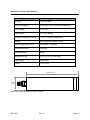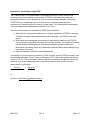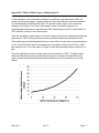
1
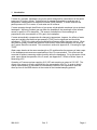
User’s Manual April 30, 2015 P/N 998-2410 Revision C TURNER DESIGNS 845 W. Maude Avenue Sunnyvale, CA 94085 Phone: (408) 749-0994 FAX: (408) 749-0998 Table of Contents 1. Introduction 4 2. Instrument Setup 2.1 Instrument Checklist 2.2 Optional Accessories 2.3 Gas Concentration Ranges Available 2.4 Deployment 2.5 Functional Test for C-sense 5 5 5 5 6 Maintenance 3.1 Gas Transfer Interface 3.2 Cleaning the Interface 8 8 4. Troubleshooting 9 5. Warranty 10 3. Appendices A. Sensor Specifications B. Wiring Guide C. Calculating pCO2 from C-sense Voltage Output D. Correcting for High TDGP E. Effects of Water Vapor on Measuring pCO2 F. Conversion of Common CO2 Units G. Logging Options for the C-sense 998-2410 Rev. C 13 14 15 16 17 19 20 Page 2 WASTE ELECTRICAL AND ELECTRONIC EQUIPMENT (WEEE) DIRECTIVE Turner Designs is in the business of designing and selling products that benefit the well-being of our environment. Accordingly, we are concerned with preserving the surroundings wherever our instruments are used and happy to work with customers by complying with the WEEE Directive to reduce the environmental impact resulting from the use of our products. WEEE Return Process: To arrange the return of an end-of-life product, proceed as follows: If you purchased your instrument through a Turner Designs Distributor please contact your local representative. They will instruct you where to return the end-of-life product. If you purchased your instrument directly from Turner Designs please contact Turner Designs Customer Service By Phone: 1-408-212-4041 or Toll Free: (877) 316.8049 By Email: Customer Service at [email protected] Turner Designs will provide a WEEE RMA Number, a Shipping Account Number, and a Ship to Address. Package and ship the product back to Turner Designs. The product will be dealt with per Turner Designs’ end-of-life recycling program in an environmentally friendly way. 998-2410 Rev. C Page 3 1. Introduction C-sense is a compact, lightweight, plug-n-play sensor designed for measurement of the partial pressure of CO2 gas in liquids. Combining an oil resistant hydrophobic membrane and a temperature compensated non-dispersive infrared (NDIR) detector, C-sense measures the partial pressure of CO2 in water, oil, and water and oil mixtures. C-sense operates through the diffusion of gas across a hydrophobic membrane into an isolated headspace. While any resident gas may enter the headspace, the wavelength of the infrared sensor is specific to CO2 absorption. The amount of absorption of that wavelength is proportional to the concentration of CO2 gas in the headspace. C-sense automatically compensates for changes in temperature, however, the effects of water vapor and variable total dissolved gas pressure (TDGP) can be significant and should be considered. TDGP is the total pressure exhibited by all gasses within the water column. When this pressure greatly exceeds the pressure at which the C-sense was calibrated, the output of the C-sense should be corrected. This correction is outlined in Appendix D, “Correcting for High TDGP.” Water vapor absorbs at the same wavelength as CO2 and therefore the presence of water vapor in the headspace can cause an overestimation of the CO2 concentration. This effect can’t be corrected for without measuring relative humidity within the headspace. For a discussion of how water vapor affects the operation of the C-sense, see Appendix E, “Effects of Water Vapor on Measuring pCO2.” Operation of C-sense requires supplying 6-12 VDC and recording an output of 0-5 VDC. The output of the sensor is directly proportional to the concentration of pCO2. In order to obtain quality measurements, a user needs to understand the effects of the equilibration time and warm-up time of the NDIR detector in the context of the intended sampling protocol. 998-2410 Rev. C Page 4 2. Instrument Setup 2.1 Instrument Checklist Each sensor purchase comes complete with: C-sense Analog Sensor with a 4-pin Impulse connector (MCBH(WB)-4-MP-SS) Copper tape cut outs (30 ea.) P/N: 2400-506 USB drive with documentation 2.2 Optional Accessories Pigtail Cables with Locking Sleeve 0.6 meter pigtail cable with locking sleeve P/N: 105-2410 5 meter pigtail cable with locking sleeve P/N: 105-2411 10 meter pigtail cable with locking sleeve P/N: 105-2412 25 meter pigtail cable with locking sleeve P/N: 105-2413 50 meter pigtail cable with locking sleeve P/N: 105-2414 Water-Pumped Head P/N: 2400-700 2.3 Gas Concentration Ranges Available 0–1000 ppm P/N: 2400-001 0–2000 ppm P/N: 2400-002 0–4000 ppm P/N: 2400-004 Other C-sense ranges available by special order 2.4 Deployment Turner Designs recommends the sensor be deployed horizontally in order to reduce or eliminate particulates in the water column from settling on the semi-permeable membrane and to release gas bubbles trapped or formed on the membrane surface. An alternative solution to these potential sources of error is the use of the Water Pumped Head (PN: 2400-700). The shear forces generated by pumping water past the membrane will prevent settling of particulates as well as force bubbles out of the sample volume. In addition, the Water Pumped Head has the advantage of decreasing equilibration times. 998-2410 Rev. C Page 5 2.5 Functional Test for C-sense To perform a functional check on the C-sense, connect the colored wires from the pigtail to the power supply and multi-meter as shown in Figure 1 below. Additional Equipment required for functional tests: DC Power Supply, 6 - 12 VDC, >100 mA Multi-meter to read 0 - 5 VDC Note: Supply voltages greater than 13.5 VDC will result in damage to the sensor. DC Power Supply 12.00 .015 + 4 3 1 2 Multimeter - PSU Positive Connection (Red) 3.52 Supply Ground 0 VDC (Black) 10 VDC Signal Output “+” (White) C-sense Pigtail Cable + Figure 1. - Analog Ground “-” (Green) With the C-sense connected as shown in Figure 1, answer the following questions to verify the sensor is functional: 1. Is there voltage output? The C-sense has a 45 second “warm-up" period during which the output values will be zero or near zero. After 45 seconds the output voltage should be at a level that corresponds to at least 400 ppm. This voltage can be calculated using the equation on your C-sense calibration sheet. For instance, if the equation on your calibration sheet is: y = 806.85x – 42.403 where y is the concentration of CO2 in ppm, and x is the voltage from the C-sense in volts, set the concentration to 400 ppm and solve for x. 998-2410 Rev. C Page 6 x = (400 + 42.403)/806.85 = 0.5483 Therefore, this C-sense sensor should output 0.5483 volts when the pCO2 concentration is 400 ppm. 2. Does the voltage output change? To cause a change in the output voltage breathe across the membrane for at least one second. Human breath contains ~40,000-50,000 ppm of CO2, therefore this should result in a significant increase in output voltage. Note: Moving the sensor in air may not result in any change. 998-2410 Rev. C Page 7 3. Maintenance 3.1 Gas Transfer Interface The only component of the C-sense requiring maintenance is the gas transfer interface, a semi-permeable hydrophobic membrane. The membrane assembly is extremely sensitive and should never be disassembled or touched. The membrane and sensor face are engineered to minimize biofouling, however, under most conditions biofilms will slowly form on the surface of the membrane resulting in: An increase in equilibration time due to decreased permeability of the membrane. Reduced accuracy of CO2 estimates due to production of CO2 by organisms contained within the biofilm. Care should be taken to ensure that the interface is not damaged through scratching or extreme gas overpressure. Small surface scratches on the interface can result in sudden failure and flooding of the instrument under large pressures, either hydrostatic or dissolved gas pressure. The outlined procedure for cleaning the interface (section 3.2) should be strictly adhered to. In environments where total dissolved gas pressure (TDGP) is substantially above atmospheric pressure, caution is required when removing the sensor from water. As water pressure compresses the membrane against a pressure plate when submerged, any gas pressure buildup on the reverse side of the membrane can result in bulging of the membrane when removed from immersion. In cases of high TDGP, it is recommended to slowly bring the sensor to the surface while monitoring gas pressure. The excess gas pressure will slowly dissipate as the sensor approaches waters in equilibrium with the atmosphere. In addition, high TDGP causes significant error in the estimate of pCO2 by the C-sense. See Appendix D for a discussion on how to correct for TDGP. 3.2 Cleaning the Interface Biofilms can develop on the interface and alter the signal and response time of the instrument. Regular cleaning will minimize this effect. To clean the membrane interface: 1) Prepare a cleaning solution in an open container with 50 ml of liquid laundry detergent added to 20 liters of fresh water. 2) Place the sensor into the container and, using a small water pump, direct the flow of solution onto the membrane surface for 30 minutes. 3) Drain the container and refill with fresh water only. 4) Rinse the interface with fresh water using the water pump for 10 minutes. 5) Repeat steps 3 and 4. 6) If biofilms remain, repeat the process while extending step 2 to between 2 and12 hours. Caution: Do NOT touch the membrane for any reason. The use of any object (sponge for example) to clean the interface can result in scratching by dragging particles across the membrane surface. 998-2410 Rev. C Page 8 4. Troubleshooting 4.1 No output voltage: Check power connections and ensure power supply is between 6 and 12 V DC. Check connector diagram to ensure instrument is wired correctly. The sensor is reverse polarity protected, however, applying power to the output signal pin may result in failure. 4.2 Output reading remains at 0 V, 0.8 V or other voltage: Detector fault. The most probable cause is rapid change in conditions, typically temperature; wait for signal to return (5-15 seconds). Water damage. Check for water underneath the membrane as well as the location of a possible puncture. In the case of water damage, factory membrane and detector replacement is required. Contact Turner Designs Technical Support [email protected] for an RMA. 4.3 The instrument does not read 400 ppm in air: A common thought is that the sensor will read 400 ppm in air. This is false. Typically readings are around 450 ppm outside and anywhere from 500-1500 ppm in buildings and labs. 4.4 During lab testing (in air) the sensor reads too high or shows large fluctuations: Human breath contains ~40,000-50,000 ppm CO2, ensure sensor head is pointed away from human exhalation. 4.5 Equilibration time is really slow Biofilm or other foreign substance could be on the membrane. Follow the cleaning procedure in section 3.2. 4.6 Membrane appears loose or bulged: This can happen if the sensor was removed from high total dissolved gas pressure water too rapidly and the gas pressure behind the membrane greatly exceeded the hydrostatic pressure. Contact Turner Designs Technical Support [email protected]. 998-2410 Rev. C Page 9 5. Warranty 5.1 Warranty Terms Turner Designs warrants the C-sense and accessories to be free from defects in materials and workmanship under normal use and service for a period of 12 months from the date of shipment from Turner Designs with the following restrictions. Turner Designs is not responsible for replacing parts damaged by accident or neglect. Damage to the sensor or other internal electronics as a result of flooding from either a punctured membrane or an improperly user-applied o-ring seal is not covered under this warranty. Care must be taken to deploy instruments according to procedures described in this manual to minimize the possibility of damage due to flooding. Damage from corrosion is not covered. Enhanced corrosion activity and damage may result from improper electrical isolation between the C-sense and any supporting platforms attached to the instrument. Damage caused by customer modification of the instrument is not covered. This warranty covers only Turner Designs products and is not extended to equipment used with our products. We are not responsible for incidental or consequential damages, except in those states where this limitation is not allowed. This warranty gives you specific legal rights and you may have other rights which vary from state to state. Damage incurred in shipping is not covered. Failure of gas permeable membranes are not covered under this warranty. Welded mounting tabs and other mechanisms used to mount Turner Designs instruments to ships, buoys, mooring lines etc., are not covered under this warranty. Turner Designs expects the best and safest engineering practices to be applied by knowledgeable and experienced persons during the deployment and recovery of their instruments and cannot be held liable for any injuries or damages incurred during use of their instruments. 5.2 Warranty Service To obtain service during the warranty period, the owner shall take the following steps: 1. Write, email or call Turner Designs Technical Support and describe as precisely as possible the nature of the problem. Phone: 1 (877) 316-8049 Email: [email protected] 2. Carry out any adjustments or tests as suggested by Technical Support. 998-2410 Rev. C Page 10 3. If proper performance is not obtained you will be issued a Return Materials Authorization number (RMA) to reference. Package the unit, write the RMA number on the outside of the shipping carton, and ship the instrument, prepaid, to Turner Designs. If the failure is covered under the warranty terms the instrument will be repaired and returned free of charge, for all customers in the contiguous continental United States. For customers outside of the contiguous continental United States who purchased equipment from one of our authorized distributors, contact the distributor. If you purchased directly, contact us. We will repair the instrument at no charge. Customer pays for shipping, duties, and documentation to Turner Designs. Turner Designs pays for return shipment (custom duties, taxes and fees are the responsibility of the customer). 5.4 Out-of-Warranty Service Follow steps for Warranty Service as listed above. If Technical Support can assist you by phone or correspondence, we will be glad to, at no charge. Repair service will be billed on a fixed price basis, plus any applicable duties and/or taxes. Shipment to Turner Designs should be prepaid. Your bill will include return shipment freight charges. Address for Shipment: Turner Designs, Inc. 845 W. Maude Ave. Sunnyvale, CA 94085 998-2410 Rev. C Page 11 998-2410 Rev. C Page 12 Appendix A: Sensor Specifications Parameter Specification Accuracy 3% of full scale Power Consumption 80 mA @ 6 VDC (100 mA during warmup) Input Voltage 6 - 12 VDC Signal Output 0 - 5 VDC Analog Operating Temperature Range -2 to 35 °C Water Temperature Detector Non-Dispersive Infrared (NDIR) Detector Stabilization Time 45 seconds - 3 minutes t63 equilibration time 4 minutes Housing Material Delrin® Dimensions (LxD) 8.0 x 1.97 in. (20.3 x 5.0 cm) Depth Rating 600 meters Weight <1 lb, 430 g 203 mm (8.0”) 50 mm (1.97”) Figure AA1. Outer dimensions of the C-sense. 998-2410 Rev. C Page 13 Appendix B: Wiring Guide Pin Number Color Red 1 Black 2 White 3 Function Connection Supply Voltage (6-12 VDC) Positive Connection PSU Supply Ground (0 VDC) Ground Connection PSU CO2 Analog Signal Out “+” 0-5 VDC Green 4 Analog Ground “-“ 0 VDC C-sense Connector Pins Multimeter Positive Connection Multimeter Negative Connection C-sense Cable Holes 4 1 1 4 3 2 2 3 Figure AB1. Pinout diagram from the back of the C-sense. The connector is a 4-pin Impulse male: MCBH(WB)-4-MP-SS. 998-2410 Rev. C Page 14 Appendix C: Calculating pCO2 from C-sense Voltage Output Below is a calibration sheet with the equation to convert voltage output from a 0-4000 ppm C-sense into pCO2 concentration in ppm. The slope and offset in this equation are determined at the factory and are specific to C-sense serial number 2400110. Be sure to use the slope and offset specific to your sensor when making this calculation. In the equation above, y is the concentration of CO2 in ppm and x is the voltage coming from the C-sense. Using the 2 points defined on the graph at 2.608 VDC and 4.97 VDC as an example: y = 806.85(2.608) – 42.403 = 2061.9 ppm y = 806.85(4.97) – 42.403 = 3967.6 ppm 998-2410 Rev. C Page 15 Appendix D: Correcting for High TDGP The C-sense output is not compensated for gas pressure and, as a result, errors can be introduced when the total dissolved gas pressure (TDGP) in the liquid being measured is significantly different from the pressure at which the instrument was calibrated. Measuring TDGP at all times is preferred, but the accuracy of the C-sense precludes significant improvement in measuring pCO2 by doing so in most cases. The instruments are calibrated at or near average sea-level atmospheric pressure of 101.3 kPa. There are several reasons for deviations of TDGP in natural waters: 1) Whenever the ocean and atmosphere are in contact, equilibration of TDGP is occurring. Therefore, changes in atmospheric pressure drive changes in the TDGP of the water column. 2) Both natural and anthropogenic processes are responsible for adding to the TDGP of natural waters by generating turbulence at the air-sea interface. An example of a natural process would be breaking waves, while an anthropogenic process would be the disturbance of the water column by mechanisms associated with maritime transport (e.g. boat wakes, prop wash) 3) Natural processes of respiration and photosynthesis Correcting the C-sense signal for deviations in TDGP is simple, provided TDGP is known or can be reasonably estimated. Each C-sense is calibrated at 20º C and an atmospheric pressure at or near 101.3 kPa. The actual pressure during calibration is stated on the calibration sheet and should be used in the following equation to calculate a corrected pCO2 (pCO2cor) from a measured pCO2 (pCO2mea): pCO2cor = pCO2mea calibration pressure TDGP or, pCO2cor = (pCO2mea * calibration pressure) TDGP 998-2410 Rev. C Page 16 Appendix E: Effects of Water Vapor on Measuring pCO2 C-sense employs a semi-permeable membrane to equilibrate a gas head space within the sensor with surrounding water. All gases dissolved in the water transfer across the membrane into the head space, including water vapor. The amount of water vapor in air is commonly referred to as humidity. For a sensor submerged in water, the relative humidity of an equilibrated gas head space is approximately 100%. Measurement of pCO2 in this condition of 100% humidity is called a “wet” measurement. There are two effects of water vapor on the pCO2 reading of the sensor, elevated total dissolved gas pressure, TDGP, and a phenomenon called “pressure broadening of absorbance lines.” The broadening of spectral absorbance lines is a minor effect of water vapor on the absorbance of CO2 at low CO2 levels and at low temperatures. For example, the error in pCO2 for a 1000 ppm sample at 30º C is on the order of 4-6 ppm. At half this temperature the error drops to 2-3 ppm. The more significant error due to water vapor is the contribution to TDGP. The figure below shows the total partial pressure exerted by water vapor as a function of temperature of the water. As water temperature increases the partial pressure of H2O increases in a non-linear fashion. 998-2410 Rev. C Page 17 Example: pCO2 measured = 1000 ppm Calibration pressure = 1000 mbar Atmospheric pressure = 1000 mbar Temperature of water = 20º C If the sensor was measuring CO2 in the air, there would be no correction needed for pressure as the calibration pressure and atmospheric pressure are the same. In water however, the TDGP is greater than atmospheric pressure due to the added partial pressure of H2O. From the previous figure, at 20º C, an additional 20 mbar of gas pressure will be present in the water (and sensor gas head space). This equals a TDGP of 1020 mbar. Using the following equation where pCO2cor is corrected pCO2 and pCO2mea is the value measured by the C-sense: pCO2cor = (pCO2mea * calibration pressure) = 1000 ppm * 1000 mbar TDGP 1020 mbar pCO2cor = 980.4 ppm Corrected pCO2: ~980 ppm. 998-2410 Rev. C Page 18 Appendix F: Conversion of Common CO2 Units Gaseous CO2 is commonly measured in units of parts per million (ppm). This is the ratio of the number of CO2 molecules per million molecules of air. The ppm of CO2 in air does not change with pressure. The ppm CO2 is also referred to as the mixing ratio, xCO2. In natural waters, CO2 (g) is often reported as a partial pressure, pCO2, with units of microatmospheres (µatm). Unlike xCO2, pCO2 is dependent on the total dissolved gas pressure. The two terms are related by pressure and the following equation: pCO2 = xCO2 * P Where P is the pressure measured in atmospheres. To convert an output from the C-sense of 430 ppm to µatm, divide the ppm (µmol/mol) value of 430 by 1x106. 430 µmol / mol 1x10⁶ µmol / mol = 4.3x10⁻⁴ (unitless) Then multiply that unitless ratio by the TDGP in units of µatm. If TDGP is 1.0005 atm, first convert to µatm by multiplying by 1x10⁶, resulting in 1000500 µatm. 4.3x10-4 * 1000500 µatm = 430.2150 µatm From this example it follows that differences in the value of pCO2 in units pf ppm and units of µatm, are a function of the TDGP. When TDGP is close to or at atmospheric pressure, the value of pCO2 in units of ppm and µatm are similar. As the TDGP becomes more significant, so does the difference between pCO2 in units of ppm and µatm. A third unit of measure for CO2 is the fugacity (fCO2). The fugacity corrects for non-ideal gas behavior and can be estimated from approximate expressions along with the temperature and pCO2. In most cases fCO2 is within a few µatm of the pCO2. 998-2410 Rev. C Page 19 Appendix G: Logging Options for the C-sense At present, there are two supported logging options for the C-sense DataBank Datalogger: For instructions on how to interface the C-sense with the Handheld DataBank or the DataBank Station, see the Quick Start Guide at the following web address: http://www.turnerdesigns.com/t2/doc/tech-notes/998-2906.pdf Campbell Scientific CR1000: For instructions on how to interface the C-sense with the CR1000 datalogger, see the technical note at the following web address: http://www.turnerdesigns.com/t2/doc/tech-notes/S-0162.pdf PME C-sense Logger: For instructions on how to interface the C-sense with the PME C-sense Logger, see the manual at the following web address: http://pme.com/wp-content/uploads/2015/02/C-sense-Logger-Manual.pdf. 998-2410 Rev. C Page 20 998-2410 Rev. C Page 21