1
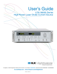
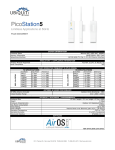
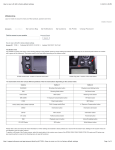
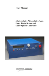
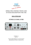
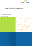
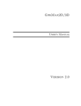
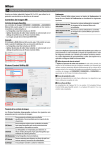
The Laser/LED driver Model D3100
User Manual
Microsensor Technology
2012
1
Table of Contents
Table of Contents .......................................................................................................................................... 2
1. Introduction .............................................................................................................................................. 3
2. Features and specifications....................................................................................................................... 3
2.1 Quasi Continuous Wave mode ........................................................................................................... 3
2.2 Pulse mode.......................................................................................................................................... 3
2.3 Some Limitations................................................................................................................................. 4
2.4 Technical Specifocations ..................................................................................................................... 5
3. Operating conditions ................................................................................................................................ 5
4. Control panel and connection guide ......................................................................................................... 5
5. Operating instruction ................................................................................................................................ 7
5.1 Power connection ............................................................................................................................... 7
5.2 LED connection ................................................................................................................................... 7
5.3 Synchronization connection................................................................................................................ 7
5.4 Power On and OFF .............................................................................................................................. 7
5.5 Operation mode selection .................................................................................................................. 7
5.6 Parameter selection ............................................................................................................................ 8
5.7 Parameter adjustment ........................................................................................................................ 8
5.8 Safety information .............................................................................................................................. 8
2
1. Introduction
The Model D3100 is designed to drive semiconductor laser diodes or Light Emitting diodes
(LEDs) as a current source. The user can select between the two operation modes, QuasiContinuous Wave (QCW) mode or Pulse Wave (Pulse) mode.
2. Features and specifications
The driver D-3100 provides two modes of operation: Quasi Continuous Wave mode (the mode
to provide maximum average optical power from the LED) and pulse mode (the mode to
provide maximum peak optical power from the LED).
2.1 Quasi Continuous Wave mode
Frequency: The frequency can be tuned in discrete steps in range of 1- 20 kHz (1, 2, 4, 8, 10, 12,
16, 20 kHz, with a Frequency Accurancy of ±10Hz).
The Current Amplitute: The current amplitute can also be adjusted in steps of 25 mA (25, 50,
75, 100, 125, 150, 175, 200, 225, 250mA, Accuancy ±1 mA);
The pulse waveform: Square wave(rise time [from 10% to 90%]/fall time <100ns),duty
cycle is 50% (with accurancy ±1% or <±2 μs) (For example: 1, 2 , 8 and 16 kHz corresponding
to 500, 1000 μs, 250 μs, 62 μs and 31 μs.)
Figure 1 Current-time relation in case of continuous wave mode.
2.2 Pulse mode
Frequency: The frequency can be tuned in discrete steps (1,2,4,8,10,12,16,20 kHz, with a
Frequency Accurancy of ±10Hz)
3
The Current Amplitute: The current amplitute can also be adjusted in steps of: 25, 50, 100, 200,
300, 400, 500, 600, 700, 800, 900, 1000, 1200, 1400, 1600, 1800, 2000 mA, with accurancy of
±10 mA.
The pulse waveform: Square wave: Square wave (rise time [from 10% to 90%]/fall time <100ns),
with pulse width adjustable in discrete steps: 0.5, 0.8, 1.0, 1.2, 2.0, 4.0, 8.0, 10.0, 15.0, 20.0 us,
(Accuracy: ±0.1 us).
Figure 2 Current-time relation in case of pulse mode.
2.3 Some Limitations
Note: please do not use the combination of frequency and pulse duration that gives a duty
cycle more than 10 percent (table 1).
We recommend to use the pulse current amplitude to 2A only at pulse duration less than 1 μs.
Otherwise the LED could be damaged.
4
2.4 Technical Specifocations
Input Voltage
Voltage Tolerance
Power Consumption
Adjustable Temperature range
Weight
Dimension
Pulse Duration
Repetition Rate (Freq)
Output Current Amp
+12 VDC, Stabalized
+/- 5%
Less than 4 W
-10 °С to +25 °С
XXX g
5“ (H) X 3“ (W) X 1½“ (D)
QCW Mode
Pulse Mode
0.5 to 20 uA
1 to 20 kHz
25 mA to 2000 mA
1 to 20 kHz
25 to 250 mA
3. Operating conditions
Operating Temperature
Relative air Humidity (at temperature + 35°С)
Atmospheric Pressure
Power Supply
EXT Synchronization Output (Negative Pulse)
-15 °С..+50
less than 80
86..107
12
TTL
°С
%
kPa
VDC
4. Control panel and connection guide
The DC power, LED connector, and synchronization connector are located on the top panel of
the D3100 driver as indicated below (View from Top):
①
②
5
③
Where:
(1) is the LED connector
(2) is the synchronization connector
(3) is the +12 VDC connector
The front panel of the D3100 is shown in below:
④
⑤
⑦
⑥
And the functions of each control and display are listed as follows:
(4)
(5)
(6)
(7)
the display:
the power Switch
The Mode Selection Switch
The Parameter Selection and Adjust Push Button
a. Top (Up): to increase the parameter
b. Middle: to select the parameter
c. Bottom (Down): to decrease the parameter
6
5. Operating instruction
5.1 Power connection
Customer need to provide the +12 VDC power supply for the D3100. The plug-in connector (3)
is a male type connector with O.D of 0.2” (~5 mm). The center connector is Positive (+) and the
outer connection is the negative (-).
The user can provide the +12 VDC power themselves or buy the optional power adapter from
Microsensor Technology (DC-12V-0001)
5.2 LED connection
The LED connection cable is provided with the driver where the number 1 and 2 on the LED
socket indicates the Anode and Cathode of the LED. The “RED” dot on the LED should connect
to the Anode (number 1 on socket).
The SMA connector should be ONLY connected to the LED connector (1).
5.3 Synchronization connection
The Synchronization connection cable is not provided with the package. The connector (2) on
the D3100 is a SMA connector with a negative TTL pulse output. (center is negative) Please take
precaution to ensure the polarity when you buy or make the cable.
5.4 Power On and OFF
The Power ON/OFF switch (5) is used to turn the driver ON and OFF.
The Power will be turned ON when the switch is in upper (ON) position
The Power will be turned OFF when the switch is in lower (OFF) position
5.5 Operation mode selection
There two operating mode can be selected with the D3100: QCW and Pulse with the mode
selection switch (6). The detailed description on the QCW and Pulse mode can be found in
section 2 of this manual.
The QCW mode is selected when the switch is in the lower position.
7
The Pulse mode is selected when the switch is in the upper position.
5.6 Parameter selection
The parameter selection button (7.b) is located in the middle position of the three push buttons
on the right side of the front panel.
There are three parameters can be selected by this button.
Frequency (in kHz)
Current (in mA)
And Pulse Width (in micro-seconds)
The LED display will flash when the parameter is selected.
Please note that only Frequency and Current can be adjusted when the QCW operating mode is
selected.
5.7 Parameter adjustment
After the parameter is selected, the use can use the Up (7.a) and Down (7.c) push button to
adjust the parameter in the predefined distinction values. (detailed can be found in section 2)
For example: after the Frequency is selected, the user can push the up button to increase the
frequency from 1 kHz to 2 kHz, 4 kHz, etc.
5.8 Safety information
WARNING: Mistake of connect LED to the synchronization output (2) could cause the damage
to the LED device!
8