1
Getting Started • Starting Up an ACOPOS Servo Drive
2. Starting Up an ACOPOS Servo Drive
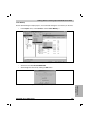
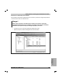
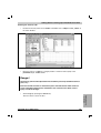
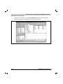
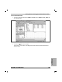
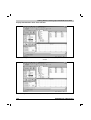
The goal of the following example is move the shaft of a motor connected to an ACOPOS servo
drive 5000 units. In order to emphasize the important points of starting up the hardware, this will
be done using an sample project contained in B&R Automation Studio™.
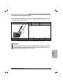
Danger!
Incorrect control of motors or mechanical parts connected to the motor shaft can
cause unwanted and dangerous movements!
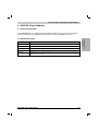
2.1 General Information
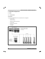
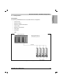
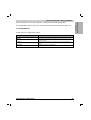
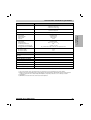
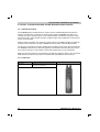
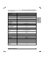
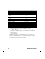
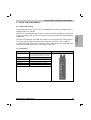
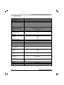
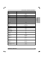
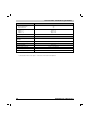
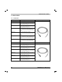
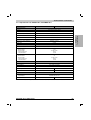
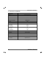
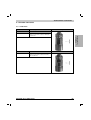
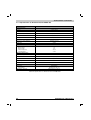
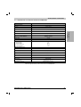
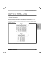
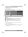
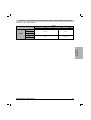
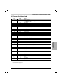
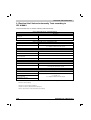
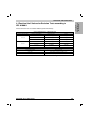
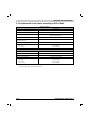
The start-up procedure described here is based on the following configuration: 1)
Model Number
Short Description
Servo Drives
8V1045.00-1
Servo drive 3 x 400-480V 4.4A 2kW, line filter and braking resistor integrated
Plug-in Modules
8AC110.60-1
8AC120.60-1
ACOPOS plug-in module, CAN interface
ACOPOS plug-in module, EnDat encoder interface
Motor
8MSA4L.E0-B4
Motor MSA4 series with EnDat encoder
Accessories
7AC911.9
Bus connector, CAN (2 pcs.)
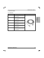
8CE005.12-1
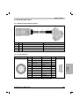
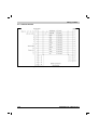
EnDat cable, length 5m, 10 x 0.14mm² + 2 x 0.5mm², EnDat connector 17 pin Intercontec
socket, servo connector 15 pin DSUB plug, can be used in cable drag chains, UL/CSA
listed
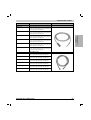
8CM005.12-1
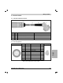
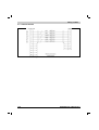
Motor cable, length 5m, 4 x 1.5mm² + 2 x 2 x 0.75mm², motor connector 8 pin Intercontec
socket, can be used in cable drag chains, UL/CSA listed
0G0001.00-090
Cable PC <--> PLC/PW, RS232, Online cable
PLC CPU
7CP476.60-1
2003 CPU, 750 KB SRAM, 1.5 MB FlashPROM, 24 VDC, 12.5 W supply, 1 RS232
interface, 1 CAN interface, CAN: electrically isolated, network capable, 4 slots for screw-in
modules, system bus for expansion modules, max. 272 digital / 80 analog I/O points
B&R Automation Studio™
1A4000.Lx
B&R AutomationSoftware™ CD, full version
Table 73: Configuration for the start-up example
1) The procedure can change slightly depending on the hardware configuration.
130
ACOPOS User's Manual (V1)