1
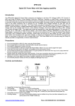
FDY10-H Battery Tester User Manual FDY10-H Battery tester is a new type instrument,which can detect the capacity of the battery, also can measure the discharge time and discharge AH of the battery.It adapts to the batteries of different kinds and models with the voltage range of 1V-60V and is mainly used to measure Ni-Cd, Li-Ion, Pb, Ni-Mh, Ag-Zn, LMP, Li-po, Pb, etc., with the discharge current range of 0.1A-10A automatic constant current and the stop discharge voltage set between 0V to 60V freely. In the discharge, the LED display the voltage, current, power, AH, time in real time.After finish discharging the battery,it will display the measurement results such as AH and discharge time . 1. Special Functions and Advantages Small size, light weight and portability High stability due to split design of the host and heating elements Small measurement error and more accurate measurement results due to application of 4-wiring-system measurement mode Availability for setting automatic slide show function to check operating states and parameters visually and clearly due to the display mode based on combination of the LED indicator light and the LED nixie tube; Operation sound prompt and alarm for finish of discharge Wider voltage detection range for the battery due to 2Wire and 3Wire detection modes Automatic identification of 12V and 16V batteries Rapid test function to detect the approximate capacity of a battery within 1-10min rapidly; Constant resistance mode Availability for battery pack of polymer lithium batteries, lithium iron batteries or lead-acid batteries, with the voltage of 12V, 16V, 24V, 36V and 48V; Series connection of power resistors (four 200W resistors at most), availability for -2- automatic identification of resistance value, and flexible wiring modes 2. Performance Indexes: 1. Final discharging voltage of battery: the final discharge voltage can be set between 0.00V and 60.00V freely, with the step value of 0.01V for the voltage below 10.00V and 0.1V for the voltage above 10.00V. The final discharge voltage in factory default is 10.50V, after starting to identify the 12V or 16V battery automatically, the final discharge voltage of the 12V storage battery is 10.50V, the final discharge voltage of the 16V storage battery is 14V, and after the automatic identification function is enabled, the final discharge voltage is automatically set by the machine, which does not support custom setup. 2. Setting the discharge current of battery: when the voltage of the battery to be detected is lower, the current can be set between 0.1A and 10A freely; and when the voltage of the battery is more than 10V, the current can be set between 0.4A and 10A freely. The step value is 0.1A under the setting mode, the step value can be set to be 1A by pressing a key rapidly. If a constant resistance function is enabled in the setting mode, the above setting is invalid. 3. Automatic identification of battery voltage: after the automatic identification function is enabled under the setting mode, the battery with the voltage below 15V is identified to be the 12V storage battery, while the battery with the voltage above 15V is identified to be the 16V storage battery. What should be noted is that the battery can be identified only under the 2W mode without connection with any power adapter, and is identified completely at the moment after connected. 4. Over-voltage protection function: when the voltage of the battery over 60V, it cannot discharge, and the instrument will be damaged when the voltage over 80V. 5. Anti-reverse protection function: when the battery is connected reversely, a larger current flows through, which may not burn down the instrument in a short time, but long time reverse is not allowed. 6. Time setting for rapid detection function: 1-10 min. 7. Start/stop: press the “OK”key once for start and press again for stop, the time and capacity are accumulated, press the key for a long time to clear the data, or it will clear automatic after interrupt the power. 8. Display content switching mode: press key to switch the display content manually,press key for a long time to set the automatic slide show mode so as to switch the display content automatically. 9. The warning of finish discharge:the LED flickering display and the buzzer alarm,press any key to remove the warning, press key check the test result. -3- 10. Cooling manner of external power resistor: natural cooling, please place the detector at a safe place due to higher working temperature. 11. Measurement range and precision and voltage: 0.00V-60.00V, with the accuracy to 0.01V and the error of ±0.5%. 12. Measurement range and precision of current: 0.00V-10.00A, with the accuracy to 0.01A and the error of ±0.1%. 13. Measurement accuracy of battery power: 0.1W. 14. Measurement accuracy of battery capacity: 0.01AH for the capacity within 100AH, 0.1Ah for the capacity exceeding 100AH, and 999.9Ah at most for display. 15. Discharge time display for battery: hour (double digits):min (double digits), for example, 02:15 represents 2 hours and 15 minutes. 16. Dimension (mm): host: 116 (length)* 90 (width)* 40 (height), power resistor: 165 (length)* 60 (width)* 30 (height) 17.Weight: host: 190g, power resistors: 450g. 3. Wiring Mode This product is available for an external power supply, which corresponds to a 3W mode, when the voltage of the detected battery is more than 5V, the external power supply is not needed and the power is supplied by the detected battery, which corresponds to a 2W mode. If you need accurate measurement or a lithium battery and other batteries with smaller voltage are measured, the 3W mode can be adopted for measurement, wherein a supporting DC5V power supply of this product needs to be used when the 3W mode is adopted. Wiring schematic diagram and method for 2W mode: -4- Schematic diagram of 2W-mode wiring Wiring Method: Wiring should be performed according to the wiring method as shown in the schematic diagram, the accompanied supporting 1Ω/200W aluminum-shell resistors (the number of which can be selected as required, please refer to Supplementary Instructions for details) shall be connected at first during wiring, the screws at the terminal blocks must be tightened, or it will be burn down the terminal blocks, and then, connect the test clip onto the storage battery. Wiring schematic diagram and method for 3W mode: Schematic diagram of 3W-mode wiring -5- Wiring Method: Wiring should be performed according to the wiring method as shown in the schematic diagram, the accompanied supporting 1 Ω /200W aluminum-shell resistors (the number of which can be selected as required, please refer to Supplementary Instructions for details) shall be connected at first during wiring, the screws at the terminal blocks shall be tightened, or it will be burn down the terminal blocks, then, the DC5V power adapter is connected to supply power to the detector, set the parameters, and finally,connect the storage battery. 4. Instructions for Use 1. Connect the battery, the LED nixie tube displays the voltage of the battery in default, the final discharge voltage of the battery is 10.5V in default, and the discharge current is 10 A in default. 2. If the discharge current needs to be changed, press the flicker at the position “A”, at this moment,press the key to make the current LED indicator light key and key to realize the rapid cyclic setting among several common discharge currents such as 1A, 2A, …, and 10 A, then press the “OK” key to confirm and quit, which is the method for rapid current setting. 3.If the final discharge voltage of the battery needs to be changed, the discharge current needs to be set based on the step value of 0.1A, or the functions of automatic battery identification, rapid detection, constant resistance mode and setting parameter saving need to be started,need enter the setting mode 4. The method of enter the setting mode: press the “OK” key for a long time, when the LED indicator light flicker at the positions “V”; then press the “OK” key for a short time to turn to different setting functions; after setting, enter the saving interface to save the parameters, it will automatically quit the setting mode after saving. If the parameters are changed temporarily without saving, press the“OK” key for a long time to quit the setting mode. The specific functions of the setting mode are shown in the following table: Function Table of Setting Mode Nixie Tube Voltage Current Display Value Value Flickering Flickering at at V A LED light ES-n AU-n F-00 Cr-n No light No light No light No light -6- Function 1 2 3 4 5 6 Automatic Rapid Setting identification detection constant of time (min) resistance number Corresponding Setting of Setting Functions final discharge discharge current of Save and quit voltage 1 12V/16V battery of mode Function 1 is used to set the final discharge voltage of the battery, the indicator light “V ”flickers correspondingly, press the or value of the battery, and press the key for a short time to increase or decrease the final discharge voltage or key for a long time to change the final discharge voltage value quickly, the step value is set to be 0.01V when the voltage is smaller than 10V and is set to be 0.1V when the voltage is more than 10V. 2 Function 2 is used to set the discharge current of the battery, the indicator light “A” flickers correspondingly, press the or value, and press the key for a long time to change the discharge current value quickly, and or key for a short time to increase or decrease the discharge current accurate regulation is performed by taking 0.1A as the step value here. 3 Function 3 is used to save the parameters, and the default ES-n indicates not save. When the parameters are set well and need to save,press the or key for a short time to switch to the display of “ES-y”, then press the “OK” key to save the current parameters and quit the setting mode automatically, and a tweet is sent out after saving, so that the saved parameters cannot be lost after power interruption. If the parameters are changed temporarily and in no need of saving,press the “OK” key for a long time to quit the debug mode. 4 Function 4 “AU-n” is used for automatic identification of the battery, which is off in default. When you need to discharge 12V and 16V batteries mainly, this function can be enabled,press the or key to turn to “AU-y”, then use function 3 to save. Under the automatic identification mode, the detector sends out one long tweet and one short tweet at the power-on moment when the 12V storage battery is connected, and sends out one long tweet and two short tweets at the power-on moment when the 16V storage battery is connected, what should be noted here is that the automatic identification is completed only at the moment when the detector is connected with the battery, and this function is effective only when the storage battery is connected under the 2W mode, and the final discharge voltage -7- cannot be changed after the automatic identification function is enabled. 5 Function 5 is the rapid detection function, and the default display of “F-00” indicating disabling the rapid detection function, which means that the conventional full discharge detection is performed at the moment. The rapid detection function is enabled when a non-zero value is set, “F-01” to “F-10” correspond to 1-10 min of the discharge time, press the or key to regulate the rapid detection time, after the rapid detection time is well set and saving and quitting operations are performed according to the function 3,press the “OK” key to start rapid detection, the detection time is the set time, and after the rapid detection is completed, the buzzer will give out an alarm and the capacity of the battery will be displayed in the LED nixie tube. (Please refer to Supplementary Instructions for rapid time setting.) 6 Function 6 is the constant resistance mode, which is off in default. Under the off condition, the system can regulate PWM automatically according to a set current value so as to make discharge current equal to the set value to obtain constant current, press the or key to turn to “Cr-y”, the setting mode is quit after saving, then the constant resistance mode is started, the constant current function is disabled automatically, the set current value is invalid, and the discharge current depends on the voltage of the battery and an external discharge resistor. (Please refer to Supplementary Instructions for a specific calculation method.) 5、After setting is completed, press the “OK” key, the run indicator light “RUN” is on, indicating that the battery is started to be discharged, after several seconds, the current can reach a set value (except for the constant resistance mode), at the moment, press the key to switch to different parameter displays, if all the parameters are expected to undergo slide show at the interval of three seconds, the key needs to be pressed for a long time for the slide show mode after the buzzer gives out a long tweet, and the slide show function can be disabled after pressing the key again for a long time. What should be noted here is that the ampere-hour of the capacity and time belong to cumulants, so a decimal point in the LED nixie tube is made in a flickering state during capacity display so as to show that the ampere-hour under discharge is in process of metering, and a colon of the LED nixie tube flickers to show that the discharge time is in process of cumulating. 6 、 Along with discharge, the voltage of the battery decreases constantly, during routing full discharge detection, when the voltage is decreased to be below the set final discharge voltage, the discharge is stopped automatically, whereas, if the rapid detection mode is started, discharge will be stopped after the set time is up and the estimated capacity of the battery is calculated automatically, meanwhile, two prompt -8- manners including flickering of the LED nixie tube and alarming of the buzzer will prompt you to check measurement results, and at the moment, you shall press any key to stop the alarming of the buzzer at first and then press the key to check each measurement result in sequence. 7、When the measurement results are checked, set to the capacity “AH” display mode and press the key for a long time to carry out zero clearing on the capacity, and set to a time “HH:MM” display mode and press the key for a long time to carry out zero clearing on the time, and the capacity and the time may undergo zero clearing automatically after power interruption. 5. Supplementary Instructions 1、The rapid detection function is a unique enhancement function of our product and can be used without discharging the battery fully before a test, the battery does not need to be discharged completely after the test, and when the remaining capacity of the battery is 25-75%, the numerical measurement is more accurate. It is a necessary condition for enhancing the measurement accuracy by setting the discharge current and discharge time reasonably, the discharge curves varies among different batteries, and the experience accumulated through constant trials is the best path to setting, and we will illustrate a general setting method as below: (1)The final discharge voltage shall be set reasonably according to battery specifications. (2)The set maximal value of the current is 1C rate generally, for example, the maximal discharge current of a 3AH battery is 3A, the detection time may be 1 min at the moment, the measurement results will be more accurate if smaller discharge current and longer measurement time are set, and an experience table is listed below for reference only: Battery Type Voltage: 12V Capacity: 12AH Voltage: 3.7V Capacity:2.5AH Final discharge voltage 10.5V 10.5V 10.5V 3.0V 3.0V 3.0V Discharge Current 10A 5A 3A 2A 1A 0.6A Rapid detection time 1 min 2 min 3 min 1 min 2 min 3 min If there is a larger deviation between the capacity obtained through rapid detection and your anticipated capacity, please charge the battery fully for a full discharge test. Or, you may try different rapid detection currents and time to find out an experience value closest to the correct capacity, which may provide experience for you to test other batteries of the same type later. 2、Constant resistance function is used to cancel the automatic constant current for PWM so as to discharge the battery directly through the external discharge resistor, this mode is unavailable for constant -9- current yet does not influence the accuracy of the metered ampere-hour, therefore, this function can be enabled if necessary, and a current calculation method is as follows: specific current=battery voltage/power resistance (with the value of 1Ω or others) 3、If the voltage of the detected battery is smaller than 10V, the maximal discharge current is not going to reach 10A, and the calculation method of the discharge current is as follows: maximal current=battery voltage/power resistance (with the value of 1Ω), for example, the maximal current corresponding to the battery with the voltage being 3.7V is only 3.7A , if the discharge current needs to be increased, the following two methods can be adopted: (1)The resistance of the external power resistor is reduced, do note: when the battery with higher voltage is measured, the resistance is ought to be switched to 1Ω, or else, the test is unlikely to be performed; (2)In case of using the resistor of 1Ω, a magnetic ring inductor of about 100uH shall be connected with the resistor in parallel, wherein any 100uH magnetic ring inductor with the maximal current reaching 10A can be selected. Table for matching relation between battery voltage and power resistor Voltage Range of Battery Number of Resistor Resistance value and Power 0~15V 1 1Ω 200W 15V~30V 2 2Ω 400W 30V~45V 3 3Ω 600W 45V~60V 4 4Ω 800W 1、The resistors are connected in series and can be increased or decreased according to actual demand. 2、The final discharge voltages of battery packs with different voltages are different and need to be set by oneself, and taking the serial connection of four 12V lead-acid batteries as an example, the final discharge voltage is 4*10.5V=42V. Notice: 1、Please reverse positive and negative electrodes when the detector is connected with a storage battery. 2、Please prohibit outrange usage. 3 、 Please place the detector at a safe place to prevent scalding since the power resistors have higher temperature during discharging at full load. - 10 -