1
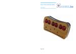
8 digits IN-12 Nixie Clock/Counter. Newly designed!
Thanks for purchasing my 8 digits IN-12 Nixie Clock/Counter.
I have tried to create stylish, reliable, accurate and easy to use Clock/Counter and I hope you
love it and this Clock/Counter is what you are really expected to see when you was looking for.
Please read carefully the information below as it helps you to use your Clock/Counter efficiently
and in proper way and hopefully will avoid any negative moments which could arise in case of
incorrect or careless use.
Clock/Counter key features:
Eight 18mm high digits (IN-12 Nixie Tubes)
Displays modes: Time , Date, 2 Alarm clock sets, Blank, 8 digits info or counter via serial port.
Accurate time clock source from internal crystal (not 50/60Hz from main).
Integrated 2 Alarm Clocks
Easy control with only 2 buttons
Now you can control and setup Date, Time and alarms from your PC via serial interface
Uses standard 9v wall plug Power Supply
Precision Seconds setup
Internal battery for data protection in case of main power failure
Will generate alarm buzz even main power is off !!!
Internal buzzer for Alarm1 and Alarm2
2 external outputs trigger on Alarm1 and Alarm2 events
Blank Mode – all digits switched off, but alarms set and clock running.
RS232 serial port connection to display or count 8 digits information from PC or other device.
The Clock functions in two main modes:
Display Mode and Setup mode
Display mode:
In the Display Mode Clock indicates the following information:
Time in format HH MM SS ,
where HH is Hours (00-12 or 00-23), MM is Minutes (0-59), SS is Seconds (00-59)
Alarm1 in format HHMM 1, where number 1 indicates Alarm1
Alarm2 in format HHMM 2, where 2 indicates Alarm2
Date in format : DDMMYY,
where DD is day (1-31), MM is Month(1-12), YY is Year (00-70)
Time and Date in format HH MM SS and DDMM.YY with 10 seconds interval
Blank/Serial Port Info, all digits are switched off or
Displays the information loaded via RS232 Serial Port in format NNNNNNNN,
where N is a digit (0-9)
Setup Mode:
Setup mode is for changing configurable parameters, allowing:
Set Current Time
Set Alarm1 time and switch it on/off
Set Alarm2 time and switch it on/off
Set Date
Set 12 or 24 Time Display mode
How to connect and control your Clock/Counter
Please use Direct Current Regulated 9V at minimum 300mA DC Current Power Supply , which
is widely available to buy on eBay or in your local shops.
Warning! Do not use or try to avoid using unregulated 9V power adapters, as under no load it
could provide up to 19v. More than 15.5v could damage your clock building dc-dc converter.
Connect your Clock/Counter to 9V power supply.
Always check that you have not mixed polarity, it would not destroy the clock, as it has wrong
polarity protection, but clock will not run.
Please refer to connection diagram to be sure you have connected it properly.
Switch your Power Supply on, Clock/Counter should start to run in Display Mode and it should
display the default current time 00:00:00.
Easily control your Clock with only 2 buttons:
Use Button1 to change displaying information. Every single push will change it in the following
order:
-> Time -> Alarm1 -> Alarm2 -> Date -> Time/Date -> Blank/Rs232info ->
|
|
----------------<------------------<-----------------<---------------<-------------------
Use Button2 to shut off buzzer when Alarm1 or Alarm2 happens.
More detailed description of buttons use:
In the Display mode you can do:
Button1. Normal push changes information to display – Time , Alarm1, Alarm2, Date or
Time/Date, Blank/RS232_Info and back to Time.
Button1. Long push leads to Setup Mode, where you can modify the appropriate values.
Button2. Normal push shuts alarm buzzer off, if it was buzzing at this moment
Button2. Long push changes time Display Mode from 24h to 12 hours scale. Second long push
will change it back from 12h to 24 hours scale.
Button1 & Button2 together. Long push leads to Frequency Test Mode. Clock will display
200000, which means 200kHz frequency output has been activated.
Please note, that the only way to leave this mode and come back to the normal Display mode is
to switch your Clock off and disconnect backup battery. All your current time, date, alarms sets
or loaded Rs232 info will be lost, so you’ll need to load or set it up again.
In Setup Mode you can do:
Button1. Normal push changes the position of highlighted digit
Button1. Long push goes back to Display Mode, where Clocks displays the current Time, Date,
Alarm1 or Alarm2 sets.
Button 2. Normal push increments the value of highlighted digit.
Button2. Long push switches off Active Alarm ( works only in Alarm1 or Alarm2 Setup mode).
How to setup Time, Date and Alarms
To set or adjust the Current Time, push Button1 until Clock starts to display time.
Now push and hold Button1 until Seconds Ones digit starts to flash.
Release Button1. You are in the Setup Mode now.
Seconds Ones digit is highlighted by flashing, so Seconds value can be reset by pushing Button2
now.
Push Button1 to highlight next digit. Push Button1 and it highlights Seconds Tens digit. You
can push Button2 to reset seconds value.
Push Button1 to highlight next to the left digit. Now Minutes Ones are flashing.
Use Button2 to set correct value. Every Button1 push will increase value by one.
Push Button1 to choose next digit to set. Minutes Tens will be flashing.
Push Button1 again in case don’t need to change Minutes tens value
Use Button2 to set correct value.
Push Button1 to choose next digit to set. Hours Ones digit should be flashing.
Use Button2 to set correct value.
Push Button1 to choose next digit to set. Hours Tens should be flashing.
Use Button2 to set correct value.
Now you set the current Time.
Push Button1 and it will highlight Seconds Ones again. Push Button1 to reset seconds value
when you need to synchronize the seconds.
Push and hold Button1 until Digit stops flashing. You have left Setup Mode.
To set the current date push Button1 until clock displays Date.
Use the same technique to set up Date.
Now push and hold Button1 until Years Ones start to flash.
Use Button2 to set correct value.
Push Button1 to choose next digit to set. Year Tens will be flashing.
Use Button2 to set correct value.
Push Button1 to choose next digit to set. Month Ones will be flashing.
Use Button2 to set correct value.
Push Button1 to choose next digit to set. Month Tens will be flashing.
Use Button2 to set correct value.
Push Button1 to choose next digit to set. Day Ones will be flashing.
Use Button2 to set correct value.
Push Button1 to choose next digit to set. Day Tens will be flashing.
Use Button2 to set correct value.
If some digits still don’t have the correct value, push Button1 until this digit is highlighted again.
Use Button2 to correct the value.
To leave Setup mode push and hold Button1 until Digit stops flashing.
Use the same technique to set Alarm1 or Alarm2.
To go to the Alarm setup mode, just choose the Alarm Time to display then push and hold
Button1 for 5 seconds. You are in the alarm setup mode now.
In this case only 4 digits can be set up and first digit is to be highlighted is Alarm Minutes Ones.
In the Alarm setup mode, when digit is flashing, as soon as you change Alarm digit Value by
pressing Button2, left or right dot separator lamp starts blinking and this Alarm will be
activated.
To de-activate Alarm, go to the Alarm Setup mode, then push and hold Button1 for 3-5 seconds.
To leave Alarm setup mode, push and hold Button2 until digit stops to flash. You are now in the
Display Mode.
How to change from 24 to 12 or from 12 to 24 Hours displaying
I recommend to do this procedure sometime after lunch, when PM time is started. It gives you
clear sign that you have changed the time scale.
Please make sure you are in Display Mode with Current Time indication.
Push and hold Button1 until Clock/Counter changes time from 24h to 12 hours scale. If you do it
after lunch, hours indication value will be changed from 13 to 01 for example.
Release Button1. Check that Clock/Counter is displaying time correctly.
Second long push will change it back from 12h to 24 hours scale.
Release Button1. Check that Clock/Counter is displaying time correctly.
Using Backup battery
Just put jumpers on the Backup battery connector to activate your current time and Alarm Sets
power failure protection.
How to load data and control Clock/Counter via RS232 serial port
Component layout diagram contains clocks RS232 pin out diagram. 3 wire serial port cable
should be used for Clock – PC interconnection.
Please use the following parameters to configure PC serial port:
Bits per second: 9600
Data bits: 8
Parity: None
Stop bits: 1
Flow control: None
Clock/Counter will automatically switch into Blank/Rs232_Info Mode and display data as soon
it gets and recognises the first byte.
Information on the display can be updated as quick as above data bit rate allows.
Always send 8 bytes of data or one command byte.
Clock/Counter accepts standard ASCII symbols, which could be sent to clock by Terminal or
any other program via serial Communication port.
To prevent incorrect digit indication and increase the reliability, limited set of ASCII symbols
can be send to the clock. All symbols are out of the below table are non-valid and will be
ignored by clock.
Send 0-9 ASCII characters to display 8 digits information on the clock Nixie tubes
Send “Space” ASCII character to switch off display digit
Send “i” ASCII character as command to increment number displayed Blank/Rs232_Info Mode
Use “t” ASCII character as command to switch into Time Display Mode
Use “d” ASCII character as command to switch into Date Display Mode
Use “a” ASCII character as command to switch into Alarm1 or between Alarm1 and Alarm2
Display Modes
Use “u” ASCII character as command to update Time, Date or Alarms sets
How to set current Time, Date or Alarms using your PC:
Connect your PC to the clock using three wires serial port cable.
Open Windows HyperTerminal or other terminal SW and configure port setting as following:
Bits per second: 9600
Data bits: 8
Parity: None
Stop bits: 1
Flow control: None
Check that communication between Clock and your PC established by sending test numeric
message to the clock – type 123 on the keyboard and 123 number should appears on your Nixie
Clock/Counter display.
Type the time you would like to clock set. For example 20 34 45 This info should be displayed
on your clock now.
Switch you clock to Time Display Mode by sending “t” command.
When current time reaches 20 34 45 push “u” button on your PC keyboard to update your clock
Now the time your clock displaying should be updated. Please not that valid values for hours is
0-23, for minutes and seconds -0-59. All values above these ranges will be ignored during update
Type the date you would like to clock set. For example 050408. This info should be displayed
on your clock now.
Switch you clock to Date Display Mode by sending “d” command.
Push “u” button on your PC keyboard to update your clock
Now the date your clock displaying should be updated. Please not that valid values for day is 131, for month is 1-12, for year - 00-70. All values above or below these ranges will be ignored
during update.
Please use the same technique to set you Alarm1 and Alarm2 values
.
Another way to understand Button1 and Button2 usage:
Button1 in Display Mode:
Normal push – switches between Display Modes
Long push - go to the Setup mode
Button1 in Setup Mode:
Normal push – choose parameter to configure
Long push - go back to the Display mode
Button2 in Display Mode:
Normal push – switch off alarm buzz
Long push – change time display mode 12 or 24 hours
Button2 in Setup Mode:
Normal push – change parameter value
Long push - switched off selected alarm
Button1 and Button2 together:
In Display Mode:
Normal push – not defined yet
Long push - go to Frequency test Mode
In Setup Mode:
Normal push – not defined yet
Long push - go to Frequency test Mode
Notice:
Please do not use this clock outside, it’s not for use in bathroom, not for use in wet condition.
Use only good quality, certified Wall Plug Power Supply, which can provide regulated, not less
than 300mA Direct Current at 9V.
Do not leave clock without main power for more than 24 hours, as It discharges your backup
battery and you need to replace it.
Some internal components are under High Voltage, so before handling or do any maintenance
work, be sure that power supply is switched off.
I do not accept any liability may cause during improper or care less use of this Clock.
Due to constant improvement, you clock design could be slightly different from the sale
description, but technical parameters and functionality will be the same or better.
The latest User Manual and other related information can be found on my WEB page at
http://www.sparkletube.com/ncounter
V01 08/04/2008