1
Vehicle Diagnosis, Testing and Information System
VAS 5051B
Operating Manual, Hardware V01.4
03/07
Contents
VAS 5051B
Contents
Safety Instructions ............................................................................................................ i
IMPORTANT SAFETY INSTRUCTIONS ........................................................................ ii
1
General Information ...........................................................................................1-1
1.1
General Notes ..................................................................................................1-1
1.2
Safety Notes ....................................................................................................1-2
1.3
EC Declaration of Conformity/CE mark ...........................................................1-2
1.4
FCC Certification ..............................................................................................1-4
1.5
Certificate of Calibration ...................................................................................1-5
1.6
Designated Use ...............................................................................................1-7
1.7
Area of Application ...........................................................................................1-7
2
2.1
2.2
Design and Mode of Operation .........................................................................2-1
Vehicle Diagnosis, Testing and Information System VAS 5051B ....................2-1
2.1.1
Scope of Delivery ................................................................................2-2
2.1.2
VAS 5051B diagnostic system ............................................................2-4
Tester VAS 5051B ...........................................................................................2-5
2.2.1
Power Supply ......................................................................................2-6
2.2.2
Front Panel .........................................................................................2-7
2.2.2.1
On/Off button ..................................................................................2-8
2.2.2.2
LED array ........................................................................................2-8
2.2.2.3
Touch Screen ...............................................................................2-10
2.2.3
Left side ............................................................................................2-11
2.2.4
Right side ..........................................................................................2-12
2.2.5
Top ....................................................................................................2-13
2.2.6
Rear ..................................................................................................2-14
2.2.7
Bluetooth interface ............................................................................2-15
2.3
Table power adapter ......................................................................................2-15
2.4
Workshop Trolley ...........................................................................................2-16
2.5
Diagnostic and measurement cables .............................................................2-19
2.5.1
Diagnostic cables 5 m (VAS 5051B/1), 3 m (VAS 5051B/2) .............2-19
2.5.2
Diagnostic adapter (VAS 5051/2) .....................................................2-20
2.5.3
OBD adapter cable (VAS 5052/16) for non-VW vehicles ..................2-21
Operating Manual VAS 5051B Hardware V01.4 03/07 All rights reserved.
A5E00309945/014
I
Contents
VAS 5051B
2.5.4
Diagnostic cable LT2 (VAS 5051B/3) ...............................................2-22
2.5.5
Test adapter cable (VAS 5051B/4) ...................................................2-23
2.5.6
U/R/D/I measurement cable (VAS 5051B/5) .....................................2-24
2.5.7
DSO measurement cables (VAS 5051B/6) .......................................2-25
2.5.8
100 A (VAS 5051B/7) and 1800 A (VAS 5051B/8) current pick-up ..2-26
2.5.9
Trigger clamp (VAS 5051/18) ...........................................................2-27
2.5.10 kV pick-up (VAS 5051/17) .................................................................2-28
2.5.11 Temperature sensor ..........................................................................2-29
2.5.12 Pressure sensors ..............................................................................2-30
2.5.13 Comparison of compatibility of VAS 505x diagnostic and measurement
cables ...............................................................................................2-31
2.6
USB keyboard and USB mouse .....................................................................2-32
2.7
Printer ............................................................................................................2-32
2.8
Optional accessories ......................................................................................2-35
2.9
Accessories that can be bought on the open market .....................................2-35
3
3.1
3.2
Operation ............................................................................................................3-1
Tester ...............................................................................................................3-1
3.1.1
Powering up the tester ........................................................................3-1
3.1.2
Touch Screen ......................................................................................3-2
3.1.3
Switching off the tester ........................................................................3-3
3.1.4
Using the tester as a table unit ...........................................................3-3
3.1.5
Interfaces ............................................................................................3-3
Workshop Trolley .............................................................................................3-4
3.2.1
3.3
Diagnostic and measurement cables ...............................................................3-6
3.3.1
3.4
4
Using the tester without a workshop trolley ........................................3-5
OBD adapter cable (VAS 5052/16) for non-VW vehicles ....................3-7
Printer ..............................................................................................................3-7
Troubleshooting .................................................................................................4-1
4.1
Classification ....................................................................................................4-1
4.2
Self-test ............................................................................................................4-2
4.3
4.2.1
Self-test of the test instruments and the diagnostic bus unit ...............4-2
4.2.2
Self-test of the online connection ........................................................4-2
Symptoms, Causes and Solutions ...................................................................4-3
Operating Manual VAS 5051B Hardware V01.4 03/07 All rights reserved.
A5E00309945/014
II
Contents
VAS 5051B
4.3.1
Tester ..................................................................................................4-3
4.3.2
Diagnostic bus, diagnostic cable .........................................................4-5
4.3.2.1
Diagnostic cable .............................................................................4-5
4.3.2.2
Diagnostic adapter (for older vehicles) ...........................................4-6
4.3.2.3
Diagnostic cable LT2 ......................................................................4-6
4.3.3
Test instruments .................................................................................4-7
4.3.3.1
Test instrument unit ........................................................................4-7
4.3.3.2
Measurement cables ......................................................................4-7
4.3.4
The printer .........................................................................................4-11
4.4
Fault Reports to Customer Service ................................................................4-11
4.5
Replacement Parts and Accessories .............................................................4-12
5
4.5.1
Overview ...........................................................................................4-12
4.5.2
General notes ...................................................................................4-12
4.5.3
Parts List for the VAS 5051B ............................................................4-14
Care and Maintenance .......................................................................................5-1
5.1
Optical check of the VAS 5051B ......................................................................5-1
5.2
Tester ...............................................................................................................5-1
5.2.1
Cleaning the touch screen ..................................................................5-2
5.2.2
Battery ................................................................................................5-2
5.2.3
Replacing the battery ..........................................................................5-3
5.2.4
Replacing the fans ..............................................................................5-5
5.2.5
Replacing the corner pieces ...............................................................5-7
5.3
Workshop Trolley .............................................................................................5-8
5.4
Diagnostic and measurement cables ...............................................................5-8
5.4.1
Changing the measuring tips on the red/black probe tip .....................5-8
5.5
Printer ..............................................................................................................5-8
5.6
Calibration ........................................................................................................5-8
6
6.1
Technical Specifications ....................................................................................6-1
VAS 5051B Tester ...........................................................................................6-1
6.1.1
Operating Data ....................................................................................6-1
6.2
Table power adapter ........................................................................................6-4
6.3
Test Instruments ..............................................................................................6-5
6.3.1
Multimeter ...........................................................................................6-5
Operating Manual VAS 5051B Hardware V01.4 03/07 All rights reserved.
A5E00309945/014
III
Contents
VAS 5051B
6.3.2
Digital Storage Oscilloscope (DSO) ..................................................6-10
6.4
Diagnostic cables ...........................................................................................6-13
6.5
Mains cable on Workshop Trolley ..................................................................6-13
7
Terms ...................................................................................................................7-1
8
Index ..................................................................................................................8-1
Operating Manual VAS 5051B Hardware V01.4 03/07 All rights reserved.
A5E00309945/014
IV
Contents
VAS 5051B
Associated Documents
Along with this operating manual, which is to be used by the user in the workshop, there
are also the following technical documents for the VAS 5051B:
•
/1/ Start-up/unpacking instructions VAS 5051B
with important information on startup and registration of the device.
This documentation is a component part of the scope of delivery.
•
/2/ Brief instructions VAS 5051B
Foldout sheet with a brief summary of the operation and use of the device. This printed
documentation is a part of the scope of delivery.
•
/3/ Operating manual VAS 505x Software
Description of the vehicle diagnosis system with detailed information on the operating
modes that can be reached through the start mask. In addition, the operating manual
contains the service addresses and forms for the registration of the device and fault
reports. Operating manuals can be opened on the tester by the administration. They
are located on the base CD.
•
•
/4/ VAS 505x service information
contains important information, addresses and telephone hotllines in case of a fault.
•
/5/ Operating Manual VAS 5051
Refer to the operating manual VAS 5051, Hardware in connection with the VAS 5051
workshop trolley.
•
/6/ User Manual, Printer
The documentation about the printer is included in the delivery scope of the printer.
See also the data medium enclosed.
In the running text a reference to the applicable documents appears as follows:
Text....(for further information see /3/).
Operating Manual VAS 5051B Hardware V01.4 03/07 All rights reserved.
A5E00309945/014
V
IMPORTANT SAFETY INSTRUCTIONS
VAS 5053
VAS 5051
VAS 5052
VAS 5051B
Safety Instructions
Meaning of symbols
The safety instructions in the operating manuals, the Startup/Unpacking Instructions or in
other documentation provided, on screen displays on the tester during operation and on
the products themselves use symbols with the following meanings:
Warning!
Text with this symbol contains information for your safety and how you can reduce the
risk of severe or fatal injury.
The WARNING
symbol warrants particular attention for your safety.
Caution!
Text with this symbol contains information about how you can avoid damage to the
vehicle and the tester.
The Caution
symbol tells you that if the information is ignored, damage to the
vehicle and/or the tester could result (e.g.: Ensure that the touch screen is not touched
with sharp, edged objects.).
Note
Text with this symbol contains additional, useful information.
A Note
symbol contains other, special instructions for using the device, and related
information.
Note on further safety instructions
The general safety instructions, which are valid for the complete VAS 505x family of
testers, are listed in the following. Further safety instructions are to be found in the
operating manuals. Therefore, please read the operating manuals before use.
Safety instructions may also appear on the screen of the tester. Follow all the
instructions displayed.
Operating Manual VAS 5051B Hardware V01.4 03/07 All rights reserved.
A5E00309945/014
i
IMPORTANT SAFETY INSTRUCTIONS
VAS 5053
VAS 5051
VAS 5052
VAS 5051B
IMPORTANT SAFETY INSTRUCTIONS
1. Warning!
Read all instructions.
2. Warning!
Do not operate equipment with a damaged cord or if the equipment has been damaged
- until it has been examined by a qualified serviceman.
3. Warning!
Do not let cord hang over edge of table, bench or counter, or come in contact with hot
manifolds or moving fan blades.
4. Warning!
An extension cord is not allowed. For testing use only specified cables.
5. Warning!
Always unplug equipment from electrical outlet when not in use. Never yank cord to pull
plug from outlet. Grasp plug and pull to disconnect.
6. Warning!
To protect against risk of fire, do not operate equipment in the vicinity of open
containers of fuel (gasoline).
Operating Manual VAS 5051B Hardware V01.4 03/07 All rights reserved.
A5E00309945/014
ii
IMPORTANT SAFETY INSTRUCTIONS
VAS 5053
VAS 5051
VAS 5052
VAS 5051B
7. Warning!
Adequate ventilation should be provided when working on operating combustion
engines.
8. Warning!
Use only as described in this manual. Use only manufactures’s recommended
attachments.
9. Warning!
Risk of explosions
The devices have internal parts which emit sparks and therefore must not be exposed
to flammable fumes. The device should be operated at least 460 mm (18 inches) above
the floor surface since fumes from fuels and other materials accumulate at floor level.
10. Warning!
All measurement cables may only be used within the measurement ranges stipulated in
the technical specifications and the descriptions in the operating manual. All
measurement pick-ups may only be used on cable whose casing is undamaged. Do not
carry out measurements on damaged cables.
11. Warning!
The devices connected to electrical power supply correspond to protection class 1 and
are fitted with a safety-tested mains cable. They may only be connected to electrical
networks with an earthed protective conductor (TN networks) or electrical outlets with
earthed protective conductors.
12. Warning!
Fluctuations and deviations in the power supply beyond the permitted range of
tolerance can lead to malfunctions and damage.
Operating Manual VAS 5051B Hardware V01.4 03/07 All rights reserved.
A5E00309945/014
iii
IMPORTANT SAFETY INSTRUCTIONS
VAS 5053
VAS 5051
VAS 5052
VAS 5051B
13. Warning!
During test drives, secure the tester with a strap on the vehicle's back seat and connect
it to the vehicle using the diagnostic cable. A second person must operate the tester
from the back seat. Operation from the front seat is too dangerous, e.g. in the event of
airbag activation.
Only for VAS 5051:
To supply the VAS 5051 with power from the vehicle battery, use only the 3 m diagnostic
cable.
14. Caution!
Electrical ignition systems carry voltages of up to approx. 30 kV. Observe general safety
guidelines for workshops at all times.
15. Caution!
If you open the tester or its accessories without authorisation or carry out improper
alterations to them, considerable risk to you and to the device may result.
16. Caution!
VAS 5051 - changing fuse
For inline current measurements with the VAS 5051, only a replacement fuse of the
same type and same amperage may be installed in order to avoid risks of fire and to
protect the device. To order original parts, refer to the corresponding chapters of the
operating manual.
17. Caution!
VAS 5051B workshop trolley - ventilation
When operating with the VAS 5051B workshop trolley, make sure that there is sufficient
ventilation for the table power adapter of the tester and for the printer. Please note that
even when the tester is switched off, the battery charging circuit remains in operation
and the printer is online (although in energy saving mode).
•
Completely open the top cover of the printer or the roll-up door during operation
(depending on the existing workshop trolley).
•
Heat-dissipation of the table power adapter must not be impaired by objects on top
of it (cable, cloth, etc.).
•
Pull the mains cable of the workshop trolley to switch off the complete device.
Operating Manual VAS 5051B Hardware V01.4 03/07 All rights reserved.
A5E00309945/014
iv
IMPORTANT SAFETY INSTRUCTIONS
VAS 5053
VAS 5051
VAS 5052
VAS 5051B
18. Caution!
when connecting non-VW vehicles
The VAS 505x diagnostic devices were developed for vehicles from the Volkswagen
group. If the tester is connected directly to vehicles from other manufacturers, damage
to the vehicle could result.
Therefore if non-VW vehicles are to be tested using the general OBD functions in the
Vehicle Self-Diagnosis application, the OBD adapter cable VAS 5052/16 needs to be
connected between the diagnostic cable and the diagnostic connection on the vehicle
(with fewer cable connections).
19. Caution!
•
•
•
•
when handling the battery
The battery may only be replaced by trained personnel.
Never short-circuit the battery.
Never throw the battery into a fire.
Dispose of or recycle the battery in accordance to the local regulations.
SAVE THESE INSTRUCTIONS!
Release: 2005-03-30
Operating Manual VAS 5051B Hardware V01.4 03/07 All rights reserved.
A5E00309945/014
v
General Information
VAS 5051B
1
General Information
1.1
General Notes
This operating manual contains the required information for the using the vehicle diagnosis, measuring and information systemVAS 5051B, in further text abbreviated as
"VAS 5051B". It is intended for qualified technical personnel who have the appropriate
knowledge in the field of vehicle self-diagnosis and test instruments.
Knowledge and technically correct implementation of the safety instructions and warnings contained in this operating manual are the prerequisites for the safe starting-up of
the VAS 5051B as well as for safety during operation and maintenance.
Due to space limitations, this operating manual cannot cover all possible details regarding the ➚hardware1, nor does it cover every conceivable circumstance of start-up, operation, care or maintenance.
Furthermore, the ➚masks displayed here may deviate slightly in content from the masks
displayed on the tester.
Due to the overlapping validity of much of the information for the VAS 505x tester family,
the operating manual has been divided into the following sections:
Operating Manual, VAS 5051B Hardware (this document) and
•
Operating Manual, VAS 505x Software (description of the operating modes of the
tester and the applications at the vehicle), /3/.
Tester-specific differences are designated by text and/or symbols. The "VAS 505x" type
ID stands for VAS 5051, VAS 5051B, VAS 5052, and VAS 5053.
•
The pages that are valid for all devices are marked in the header by symbols of the corresponding tester.
Table 1-1
Tester symbols
VAS 5051
VAS 5052
VAS 5052
VAS 5051
VAS 5051B
VAS 5053
VAS 50 53
VAS 5051B
1. The glossary arrow ➚ refers the reader to an explanation for the marked term in
Chapter 7.
Operating Manual VAS 5051B Hardware V01.4 03/07 All rights reserved.
A5E00309945/014
1-1
General Information
VAS 5051B
1.2
Safety Notes
Please observe the safety instructions for the VAS 5051B. They are located on the rear
of the device, in the operating manual (hardware and software) following the table of contents and at respective locations where they are relevant. Safety instructions specific to
applications are also displayed directly at the tester.
1.3
EC Declaration of Conformity/CE mark
The manufacturer hereby declares (Fig. 1-1) that the device as delivered complies with
the following requirements:
•
•
89/336/EEC Council Directive on the approximation of the laws of the Member States
relating to electromagnetic Compatibility (amended by 91/263/EEC, 92/31/EEC, 93/
68/EEC and 93/97/EEC)
73/23/EEC Council Directive on the approximation of the laws of the Member States
related to electrical equipment designed for use within certain voltage limits (amended
by 93/68/EEC)
Operating Manual VAS 5051B Hardware V01.4 03/07 All rights reserved.
A5E00309945/014
1-2
General Information
VAS 5051B
Fig. 1-1
EC Declaration of Conformity
Operating Manual VAS 5051B Hardware V01.4 03/07 All rights reserved.
A5E00309945/014
1-3
General Information
VAS 5051B
1.4
FCC Certification
Warnings because of built-in bluetooth transceiver:
1. Warning!
FCC 15.105: This device was examined and complies with the limit values for digital
devices, class A per part 15 of the FCC rules. These limits are designed to provide reasonable protection against harmful interference in a residential installation. This equipment generates, uses and can radiate radio frequency energy and, if not installed and
used in accordance with the instructions, may cause harmful interference to radio communications. However, there is no guarantee that interference will not occur in a particular installation. If this equipment does cause harmful interference to radio or television
reception, which can be determined by turning the equipment off and on, the user is
encouraged to try to correct the interference by one or more of the following measures:
•
Reorient or relocate the receiving antenna.
•
Increase the separation between the equipment and receiver.
•
Connect the equipment into an outlet on a circuit different from that to which the
receiver is connected.
•
Consult an experienced radio/TV technician for help.
2. Warning!
FCC 15.19: This device complies with Part 15 of the FCC Rules and with RSS-210 of
Industry Canada.
Operation is subject to the following two conditions:
1. This device may not cause harmful interference, and
2. this device must be able to accept any interference received, including interference
that may cause undesired operation.
3. Warning!
FCC 15.21: Changes or modifications made to this equipment not expressly approved
by the manufacturer may void the FCC authorization to operate this equipment.
Operating Manual VAS 5051B Hardware V01.4 03/07 All rights reserved.
A5E00309945/014
1-4
General Information
VAS 5051B
4. Warning!
This equipment complies with FCC radiation exposure limits for an uncontrolled environment. This equipment should be installed and operated with minimum distance
20 cm between the radiator and your body.
This transmitter must not be moved or operate in conjunction with any other antenna or
transmitter.
Note
A bluetooth interface application for communication with external devices, e.g. diagnostic radio head, is prepared.
Trade name: Siemens AG
Model No: VAS 5051B
FCC ID: LYHVAS5051B
IC: 267AA-VAS5051B
This device complies with Part 15 of the FCC Rules and with RSS-210 of Industry
Canada. Operation is subject to the following two conditions. (1) this device may
not cause harmful interference, and (2) this device must accept any interference
received, including interference that may cause undesired operation.
1.5
Certificate of Calibration
The manufacturer hereby declares (Fig. 1-2) that the device delivered with this operating
manual does not require any calibration within the first three years after its delivery.
Regarding calibration after this initial period, see Section 5.6.
Operating Manual VAS 5051B Hardware V01.4 03/07 All rights reserved.
A5E00309945/014
1-5
General Information
VAS 5051B
Fig. 1-2
Certificate of Calibration
Operating Manual VAS 5051B Hardware V01.4 03/07 All rights reserved.
A5E00309945/014
1-6
General Information
VAS 5051B
1.6
•
•
1.7
Designated Use
The VAS 5051B may only be used at a vehicle.
The product described has been developed, manufactured and checked according to
the relevant safety standards. If the safety instructions are observed, the start-up is
carried out as stipulated, the device is used for the intended purpose and the recommended maintenance and care is also observed, then in normal cases there is no danger regarding damages to property or for the health of persons associated with the
VAS 5051B.
Area of Application
Customer service functions, fault recognition and localization in vehicles by means of
•
•
•
•
•
•
•
➚Vehicle Self-Diagnosis
for performing basic ECU identification.
➚Guided Fault Finding
to localize a fault including identification of the vehicle, generation of a test plan based
on the existing symptoms and calling-up a function test for troubleshooting, whereby
Vehicle Self-Diagnosis, Test Instruments and documents display can all be used.
➚Guided Functions
for fast call-up of performable customer service functions for a vehicle type, e.g. coding the ECU.
➚Test Instruments
to use the integrated multimeter and the oscilloscope.
ELSA – Service Information System for VW workshops.
erWin – Information system for independent workshops.
Installable applications can also be activated directly from ➚CD-ROM.
Operating Manual VAS 5051B Hardware V01.4 03/07 All rights reserved.
A5E00309945/014
1-7
General Information
VAS 5051B
The main features of the VAS 5051B are:
•
•
•
•
•
•
•
•
•
•
•
Update of the tester software via CD or LAN
Various ➚diagnostics strategies
A switch-over function for moving between operating modes
Parallel mode of Vehicle Self-Diagnosis and Test Instruments
Display of documents for the given context
Construction that meets the demands of the workshop with a workshop trolley for
tester, printer, and suspension equipment for measurement cables and mains distribution
Battery back-up in case of a power failure or when changing the location of the workplace
Intuitive operation via ➚Touch screen
Wireless connection to the diagnostic adapter (prepared)
Printing functions
Help functions
Operating Manual VAS 5051B Hardware V01.4 03/07 All rights reserved.
A5E00309945/014
1-8
Design and Mode of Operation
VAS 5051B
2
Design and Mode of Operation
As an aid to orientation when using the equipment, this chapter describes all components of the VAS 5051B.
The actual operation of the Vehicle Diagnosis, Testing and Information System is
explained in the Operating Manual, VAS 505x "Software"/3/.
2.1
Vehicle Diagnosis, Testing and Information System
VAS 5051B
You can operate the VAS 5051B as a mobile unit in the workshop. When connected to a
vehicle via diagnostic and measurement cables, it provides electronic support for the
finding and localizing of faults.
Its main component is the tester. This remains integrated into the workshop trolley during
operation in the workshop, although it can also be operated separately, e.g. in a vehicle.
Results can be printed using a printer (customized installation of the printer is possible).
At the request of the customer, the VAS 5051B is delivered with a workshop trolley from
Fa. Knürr or Fa. Rawotec. Furthermore, it can also be used on a VAS 5051 workshop
trolley already owned by the operator. The operator must make the modifications
required to the VAS 5051 workshop trolley himself in accordance to the enclosed installation instructions and using the required mechanical components.
The tester is supplied with power either from a table power adapter integrated into the
workshop trolley, from the internal battery pack or from the vehicle's battery.
Operating Manual VAS 5051B Hardware V01.4 03/07
A5E00309945/014
All rights reserved.
2-1
Design and Mode of Operation
VAS 5051B
2.1.1
Scope of Delivery
There are several different types of delivery. These are:
•
•
•
Delivery of a complete system with workshop trolley from Fa. Knürr or Fa. Rawotec
Re-equipping of a VAS 5051 workshop trolley to VAS 5051B (required components)
and
Accessories that can be ordered (not contained in the above-mentioned scope of
delivery)
Table 2-1
Scope of Delivery VAS 5051B
Components
Delivery of
a system
Workshop trolley from Fa. Knürr or
Fa. Rawotec with cable arm and dust cover
●
Mains cable 6 m, specific to the country
●
Re-equipping of
VAS 5051
Fa. Knürr tester mount for re-equipping the
VAS 5051 workshop trolley
●
Power outlet strip from Knürr; EU or USA
version
●
Tester VAS 5051B
●
●
Table power adapter, 100 - 240 V for supplying the tester with power, DC 24 V
●
●
Mains cable for table power adapter, 3 m,
EU or USA version
●
Battery pack (VAS 5051B/14)
●
●
USB cable, 1.8 m for printer connection
●
IrDA is used
Diagnostic cable 5 m (VAS 5051B/1)
●
●
Diagnostic cable 3 m (VAS 5051B/2)
●
Test adapter cable (VAS 5051B/4) for selftest diagnostic interface
●
Diagnostic adapter (VAS 5051/2) for older
vehicles
●
●
Diagnostic cable LT2 (VAS 5051B/3) for LT
vehicles
U/R/D/I measurement cable (VAS 5051B/5)
Operating Manual VAS 5051B Hardware V01.4 03/07
A5E00309945/014
Accessories
●
●
●
All rights reserved.
2-2
Design and Mode of Operation
VAS 5051B
Table 2-1
Scope of Delivery VAS 5051B
DSO measurement cables (VAS 5051B/6),
2 pieces
●
●
Current pick-up 100 A (VAS 5051B/7)
●
existing 50 A
pick-up
Current pick-up 1800 A (VAS 5051B/8)
existing
500 A pick-up
kV pick-up (VAS 5051/17)
●
Trigger clamp (VAS 5051/18)
●
●
Temperature sensor
●
Pressure sensors
●
One set of touch pens (3 pieces, VAS 5051/11)
●
●
Test probe tips, 5 pieces, for U/R/D/I and
DSO cable (only for red/black test probes)
●
●
USB keyboard (VAS 5051B/23, specific to
the countrys refer to Section 4.5.3)
●
●
USB wheel mouse (VAS 5051B/24)
●
●
OKI printer including documentation
- EU version 230 V (220 - 240 V)
- USA version 120 V (110 -127 V)
- Japanese version 100 V
●
OBD adapter cable (VAS 5052/16) for
vehicles from another source.
●
Start-up instructions, specific to the language
●
●
Brief instructions, specific to the language
●
●
Operating Manual, VAS 5051B "Hardware",
specific to the language, on the base CD
●
●
Operating Manual, VAS 505x "Software",
specific to the language, on the base CD
●
●
There is an overview of the compatibility of the diagnostic and measurement cables
within the VAS 505x family of testers contained in Section 2.5.13.
For additional accessories that can be purchased, please refer to Section 2.9.
Operating Manual VAS 5051B Hardware V01.4 03/07
A5E00309945/014
All rights reserved.
2-3
Design and Mode of Operation
VAS 5051B
2.1.2
VAS 5051B diagnostic system
The VAS 5051B diagnostic system is comprised of the following components:
•
•
•
•
•
•
Tester (Section 2.2) with table power adapter (Section 2.3)
Workshop trolley (Section 2.4)
Diagnostic and measurement cables (Section 2.5)
Keyboard and mouse (Section 2.6)
Printer (Section 2.7)
Accessories (Section 2.8 and Section 2.9)
Fig. 2-1
VAS 5051B, to the left is the model with workshop trolley from Fa. Knürr, and to the
right with workshop trolley from Fa. Rawotec
Operating Manual VAS 5051B Hardware V01.4 03/07
A5E00309945/014
All rights reserved.
2-4
Design and Mode of Operation
VAS 5051B
2.2
Tester VAS 5051B
The tester provides several different ➚ operating modes to choose from, such as Vehicle
Self-Diagnosis, Test Instruments, Guided Fault Finding and Guided Functions. It can
therefore be used equally well as a fault reader, a measuring instrument and an intelligent fault identification system.
The operating system and the applications are stored in the tester.
The tester reacts to entries that are made by touching the ➚ touch screen directly using a
finger or the touch pen integrated into the device. Alternatively, the tester can also be
operated using the enclosed USB mouse.
The printer of the workshop trolley is operated via the USB interface. When re-equipping
a VAS 5051 workshop trolley, the already existing IrDA interface is used. The user's own
printer (USB or LAN) can also be installed in the system. The printer is setup in the
Administration.
Operating Manual VAS 5051B Hardware V01.4 03/07
A5E00309945/014
All rights reserved.
2-5
Design and Mode of Operation
VAS 5051B
2.2.1
Power Supply
The tester can be operated with an AC current between 100 and 240 V via the table
power adapter integrated into the workshop trolley or from the vehicle's on-board electrical system via the diagnostic cable. The built-in battery pack supplies the device with
power for up to 60 minutes continuously (depending on the operating mode). This
ensures that the tester does not have to be switched off when changing location.
Note
It is possible to operate the tester with power from the on-board network using the diagnostic cable (without connecting the table power adapter) only when the vehicle battery
is sufficiently charged. Its power consumption is limited to approx. 45 watt. The remainder of the required energy is taken from the battery pack of the tester. When operated in
this way, the tester should therefore not be operated with an empty battery pack.
Caution!
Printer Connection
The voltage range of the printer is different from that of the tester and limited to a particular rated voltage. Make sure when connecting the printer that it is supplied with the
correct voltage.
Operating Manual VAS 5051B Hardware V01.4 03/07
A5E00309945/014
All rights reserved.
2-6
Design and Mode of Operation
VAS 5051B
2.2.2
Front Panel
The following components are located on the front panel:
1. On/Off button
2. ➚LED array
3. Touch screen
1
2
3
Fig. 2-2
Front Panel of the Tester
Operating Manual VAS 5051B Hardware V01.4 03/07
A5E00309945/014
All rights reserved.
2-7
Design and Mode of Operation
VAS 5051B
2.2.2.1
•
•
On/Off button
To switch on the tester, press the On/Off button approx. 1 s, until the LED test starts
to flash (see Section 2.2.2.2).
To switch off the tester, press the On/Off button for approx. 1 s, until a max. of 5 s.
After 5 s, the tester is immediately turned off. You should only do this when the tester
cannot be turned off properly according to the instructions listed above.
Caution!
If the tester is switched off immediately using the On/Off button (pressed for longer than
5 s), then data may be lost and the operating system may be damaged!
Note
The tester switches on automatically when a connection has been established to the
vehicles’ on-board electrical system via the diagnostic cable and when there is enough
charge in the battery for the tester.
2.2.2.2
LED array
The three LEDs underneath the On/Off button display the operating conditions of the
tester.
LED 1
LED 2
LED 3
Fig. 2-3
LED array
After switching on the tester, an LED test is initiated. During this test, LED 1 lights up
orange and then green, LED 2 lights up yellow and LED 3 lights up red (consecutively).
The current operating conditions are then displayed.
Operating Manual VAS 5051B Hardware V01.4 03/07
A5E00309945/014
All rights reserved.
2-8
Design and Mode of Operation
VAS 5051B
Table 2-2
LED 1,
twocoloured
Meaning of the LEDs
It lights up when the tester is switched on:
•
•
•
•
•
•
LED 2,
single
colour
Green if the power supply is from the mains or from the vehicle's onboard electrical system (if both the mains and the vehicle's on-board
electrical system are connected then the device is supplied from the
mains).
Orange if the power supply is from the battery pack.
Orange (blinking) with internal power supply from the battery, and
when the charge is low.
A standard Windows system report appears before LED 1 starts to
flash orange (just as it does with laptops/notebooks):
"Low Battery
You should change your battery or switch to outlet power
immediately to keep from losing your work."
Now proceed as follows:
1. Acknowledge the message.
2. Connect the workshop trolley to the mains and establish the power
connection for the tester via the DC connection (the battery is now
charged).
It is not sufficient to connect to the vehicle's on-board electrical system via the diagnostic cable as the power consumption from the
vehicle battery is limited to a max. of 5 A. The local battery will continue to be drained.
Green/orange (blinking in alternation) with external power supply
from the mains or the on-board power supply when the battery is
removed or is defective.
Yellow when power is supplied from the vehicle's on-board electrical
system of the vehicle and from the battery (the current from the vehicle's battery is limited to a max. of 5 A and is currently insufficient).
Yellow/green (blinking briefly) Supplied from the vehicle's onboard power supply and from the battery, whereby the battery is
almost completely discharged (empty). Connect the workshop trolley
to the mains and establish the power connection for the tester via the
DC connection.
This lights up
•
•
Yellow when charging the battery and goes off after it is fully
charged (approx. 2.5 h).
Yellow (briefly flashing) when battery is almost completely drained.
Charge with low current to reactivate it. LED 1 flashes green and
orange alternately.
If the battery does not function again after two hours, stop charging.
Replace the battery.
Operating Manual VAS 5051B Hardware V01.4 03/07
A5E00309945/014
All rights reserved.
2-9
Design and Mode of Operation
VAS 5051B
Table 2-2
LED 3,
single
colour
Meaning of the LEDs
This flashes red if the tester is too hot.
If LED 3 begins to flash then the tester switches itself off automatically
after approx. 10 s. The LED keeps flashing. The fan is kept on to cool
down the tester.
If the overtemperature remains after the device has switched off then
the tester prevents itself from being switched back on until it has sufficiently cooled down.
When using the battery, the cooling-down process is limited to a maximum of 5 minutes and then the tester is turned off completely. If the
tester is switched back on while it is cooling down then the cooling-off
process is repeated again for a maximum of 5 minutes.
2.2.2.3
Touch Screen
The touch screen is the user interface. Masks with selection boxes and buttons appear on
this screen, and these should preferably be selected/pressed using the touch pen.
Energy saving mode
If the tester is not operated for several minutes then energy saving mode is switched on.
There are two energy saving modes depending on the power supply to the tester:
1. If the tester is supplied with power via the table power adapter or via the diagnostic
cable then the screen switches off after 15 minutes if it is not operated or if the programme that is currently running does not generate any continuous display on the
screen. As soon as you touch the screen near its upper edge, the last mask displayed
will be shown again. You should not touch other areas of the screen, since that could
trigger unintended programme functions. An exception to this is the Vehicle Self-Diagnosis operating mode which is ended with the blanking of the screen. The start mask
is then displayed after switching back on.
2. The screen blanks after 5 minutes when using the battery. Otherwise there are no differences here.
Operating Manual VAS 5051B Hardware V01.4 03/07
A5E00309945/014
All rights reserved.
2-10
Design and Mode of Operation
VAS 5051B
2.2.3
Left side
On the left side there are:
1. two fans
2. a protective cover for the DVD drive
3. the DVD drive
1
2
Fig. 2-4
3
Left side of the tester
Note
When you open the DVD drawer, sensitive components of the lens system are now
accessible. Make sure that these do not become dirty or damaged.
When you insert a CD or DVD, make sure that it correctly engages in the DVD drawer in
the center, re. in the bracket.
When operating the DVD drive, the tester must not be inclined by more than 15° (from
the vertical or horizontal position).
Operating Manual VAS 5051B Hardware V01.4 03/07
A5E00309945/014
All rights reserved.
2-11
Design and Mode of Operation
VAS 5051B
2.2.4
Right side
On the right side there are:
1.
2.
3.
4.
5.
6.
7.
8.
Touch pen
Chip card reader
LAN interface for network operation
Two double-layered USB interfaces for connecting a USB printer, a keyboard
(enabled for ELSA application), a mouse and an external storage device (see
Section 2.9)
➚IrDA interface for connecting a printer with an infrared interface, e.g. in a reequipped VAS 5051 workshop trolley
RS232 interface for servicing
DC input, connection for table power adapter
Audio input/output for connection of a headset (headphones)
1
2
3
4
5
6
7
8
Fig. 2-5
Right side of the tester
Operating Manual VAS 5051B Hardware V01.4 03/07
A5E00309945/014
All rights reserved.
2-12
Design and Mode of Operation
VAS 5051B
2.2.5
Top
The connections for the diagnostic cable and the measurement cable, as well as the
handle, are located on the top of the tester.
1
2
3
4
Rear
8
7
6
Front
5
Fig. 2-6
Top of the Tester
Table 2-3
Connection sockets on the top of the tester
No.
Labelling
Connection sockets for
1.
DSO2
DSO measurement cable 2
2.
DSO1
DSO measurement cable 1
3.
TZ
Trigger clamp
4.
KV
kV pick-up
5.
T/D
For temperature or pressure sensor
6.
U/R/D/I
U/R/D/I measurement cable for measuring the voltage, current and resistance, and for diodes and continuity test
7.
SZ
Current pick-up 100 A, or 1800 A; the 50 A and 500 A current
pick-ups from the VAS 5051 can also be used.
8.
DIAG
Diagnostic cable
Operating Manual VAS 5051B Hardware V01.4 03/07
A5E00309945/014
All rights reserved.
2-13
Design and Mode of Operation
VAS 5051B
2.2.6
Rear
On the rear of the tester are:
1. VGA interface
2. IrDA interface for connecting a printer with an infrared interface, e.g. in a re-equipped
VAS 5051 workshop trolley (can also be seen in Fig. 2-5)
3. Touch pen ejector
4. Two PCMCIA interfaces (underneath screw-on corner piece)
5. Window to permit viewing of control LEDs on PCMCIA cards
6. Handle
7. Bluetooth interface (underneath screw-on corner pieces)
8. Name plate with system ID and warning instructions in English. The system number
contains the production number (F-Nr.) as its last five digits. This is also identical to
the equipment number as displayed in the Administration.
9. Support leg for table operation (can be hinged out and snapped in)
10. Cover of battery compartment
5
6
7
4
3
8
9
2
1
Fig. 2-7
10
Rear of the Tester
Operating Manual VAS 5051B Hardware V01.4 03/07
A5E00309945/014
All rights reserved.
2-14
Design and Mode of Operation
VAS 5051B
2.2.7
Bluetooth interface
The device has been prepared for use with bluetooth. The bluetooth antenna is underneath the corner piece on the top left (Fig. 2-7, 7). The bluetooth function will be enabled
at a later time.
2.3
Table power adapter
The table power adapter is incorporated into the workshop trolley and is connected there
at the mains end via a mains cable with non-heating device plug to the power outlet strip.
It is connected to the DC input on the right side of the tester via an angled two-pin connector (Fig. 2-5, 7).
Fig. 2-8
Table power adapter without mains cable
Operating Manual VAS 5051B Hardware V01.4 03/07
A5E00309945/014
All rights reserved.
2-15
Design and Mode of Operation
VAS 5051B
2.4
Workshop Trolley
The workshop trolley is a mobile frame that has holding fixtures for the tester, the diagnostic and measurement cables and a printer. It has its own mains connection as well as
mains distribution via a power outlet strip.
The VAS 5051B can be moved within the workshop using the workshop trolley. You can
also place accessories on it.
The 6 m mains cable is delivered specific to the country it is to be used in (see Parts List
for the VAS 5051B).
At the request of the customer, the VAS 5051B is delivered with a workshop trolley from
Fa. Knürr or Fa. Rawotec. When required, the VAS 5051 workshop trolley can also be reequipped to hold the VAS 5051B tester.
Caution!
When operating with the workshop trolley, make sure that there is sufficient ventilation
of the table power adapter for the tester and for the printer. Please note that even when
the tester is switched off, the battery charging circuit remains in operation and the
printer is online (although in energy saving mode).
− Completely open the top cover of the printer or the roll-up door during operation.
− Heat-dissipation of the table power adapter must not be impaired by objects on
top of it (cable, cloth, etc.).
− Pull the mains cable from the workshop trolley to switch off the complete device.
Operating Manual VAS 5051B Hardware V01.4 03/07
A5E00309945/014
All rights reserved.
2-16
Design and Mode of Operation
VAS 5051B
Fig. 2-9
Workshop trolley, Fa. Knürr model
Operating Manual VAS 5051B Hardware V01.4 03/07
A5E00309945/014
All rights reserved.
2-17
Design and Mode of Operation
VAS 5051B
Fig. 2-10
Workshop trolley, Fa. Rawotec model
Fig. 2-11
Re-equipped workshop trolley VAS 5051, tester mounting
Operating Manual VAS 5051B Hardware V01.4 03/07
A5E00309945/014
All rights reserved.
2-18
Design and Mode of Operation
VAS 5051B
2.5
Diagnostic and measurement cables
The diagnostic and measurement cables form the measurement interface between the
VAS 5051B and the vehicle. They detect the measured signals from the test object and
pass them on to the VAS 5051B for further processing.
All diagnostic and measurement cables are described in the following. Which cable is
delivered with which package can be seen in Table 2-1.
2.5.1
Diagnostic cables 5 m (VAS 5051B/1), 3 m (VAS 5051B/2)
The same diagnostic cables are available in a 5 m model and also in an optional 3 m
model. They make the connection between the tester and the on-board power supply
and permit the battery voltage T30, the condition recognition of the ignition T15 (if available) and ECU identification to be monitored.
Fig. 2-12
Diagnostic cable
When connected to a vehicle, both diagnostic cables also supply the tester with power
from the vehicle's on-board electrical system. The tester will switch itself on automatically
as soon as it is connected to this supply. The diagnostic cables are designed for use on
J1850, CAN and ISO 9141 interfaces and consist of an 18-pin round plug, the cable and
a 16-pin diagnostic plug (black) for connecting to the vehicle, conforming to SAE J1962.
Note
Only VAS 5051B/1 and VAS 5051B/2 diagnostic cables may be used. Diagnostic cables
from other testers cannot be operated at the VAS 5051B.
Operating Manual VAS 5051B Hardware V01.4 03/07
A5E00309945/014
All rights reserved.
2-19
Design and Mode of Operation
VAS 5051B
2.5.2
Diagnostic adapter (VAS 5051/2)
The diagnostic adapter makes it possible to connect older vehicles with 2x2-pin diagnostic sockets to the diagnostic cable. The diagnostic adapter consists of two 2-pin diagnostic flat connectors, two cables and the 16-pin diagnostic coupling with socket contacts.
The supply of power to the tester from the vehicle's on-board electrical system via the
diagnostic cable is also facilitated by the diagnostic adapter.
Fig. 2-13
Diagnostic adapter
Note
You can use the diagnostic adapter at all VAS 505x testers.
Operating Manual VAS 5051B Hardware V01.4 03/07
A5E00309945/014
All rights reserved.
2-20
Design and Mode of Operation
VAS 5051B
2.5.3
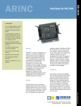
OBD adapter cable (VAS 5052/16) for non-VW vehicles
To use the generally applicable OBD functions at ➚non-VW vehicles, the following
adapter must be connected between the diagnostic cable and the diagnostic socket of
the vehicle.
Fig. 2-14
OBD adapter cable for non-VW vehicles
Caution!
The VAS 505x diagnostic devices were developed for vehicles from the Volkswagen
group. If the tester is connected directly to vehicles from other manufacturers, damage
to the vehicle could result.
Therefore if vehicles of other makes are to be tested using the general OBD functions in
the self-diagnosis application, the OBD adapter cable VAS 5052/16 needs to be connected between the diagnostic cable and the diagnostic connection on the vehicle (with
fewer cable connections).
Operating Manual VAS 5051B Hardware V01.4 03/07
A5E00309945/014
All rights reserved.
2-21
Design and Mode of Operation
VAS 5051B
2.5.4
Diagnostic cable LT2 (VAS 5051B/3)
The 3 m long, optional diagnostic cable LT2 comprises an 18-pin plug (identification:
black), the cable itself and a 14-pin diagnostic plug at the vehicle.
Fig. 2-15
Diagnostic cable LT2
The diagnostic cable LT2 enables function-oriented addressing of Daimler-Benz vehicle
systems (small commercial vehicles). This cable can also be used to monitor battery
voltage. In addition, terminal 15 is connected up so that the status "Ignition on" can be
automatically detected.
An LED array at the diagnostic cable LT2 displays the selected channel. The engine
speed can be read via the red contact plug at the cable housing.
Operating Manual VAS 5051B Hardware V01.4 03/07
A5E00309945/014
All rights reserved.
2-22
Design and Mode of Operation
VAS 5051B
2.5.5
Test adapter cable (VAS 5051B/4)
The test adapter cable is used during the self-test of the diagnostic interface. In preparation for this, the adapter cable is connected between the diagnostic cable and the diagnostic socket of the vehicle. Several leads are looped-back in the adapter cable for test
purposes. The cable gets its required power supply from the vehicles’ on-board electrical
system. The vehicle ignition must not be activated in order to be able to carry out the
self-test. Any type of vehicle can be used.
Fig. 2-16
Test adapter cable
Operating Manual VAS 5051B Hardware V01.4 03/07
A5E00309945/014
All rights reserved.
2-23
Design and Mode of Operation
VAS 5051B
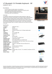
2.5.6
U/R/D/I measurement cable (VAS 5051B/5)
The 3 m long active U/R/D/I measurement cable consists of a 12-pole pin plug
(identification: purple), the cable with a housing and integrated signal processing, and
the red/black and black probe tips.
protective cap
measuring tip, 4 mm
push-button
Probe tip
Fig. 2-17
U/R/D/I measurement cable (with protective caps on the probe tips)
The U/R/D/I measurement cable is used for measuring voltages, resistances, ➚ inline
currents as well as for the diodes and continuity tests.
Caution!
when using the U/R/D/I cable.
The U/R/D/I cable (with purple identification of the pin plug) is approved only for voltage
peaks up to 42 V and current measurements up to 2 A.
Change the cable to measure higher voltages/currents!
The button on the red/black probe tip has application-specific functions such as switching on the freeze frame function, triggering a measurement, etc. For additional information, please refer to /3/, Test Instruments, Guided Fault Finding.
The measuring tip in the red/black probe tip can be unscrewed and can be obtained as a
spare part (see Parts List for the VAS 5051B).
The black probe tip can be pulled off of the cable together with the handle.
Note
You cannot use the U/R/D/I measurement cable at the VAS 5051.
Operating Manual VAS 5051B Hardware V01.4 03/07
A5E00309945/014
All rights reserved.
2-24
Design and Mode of Operation
VAS 5051B
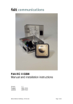
2.5.7
DSO measurement cables (VAS 5051B/6)
The two identically constructed active DSO measuring cables DSO1 and DSO2 consist
of a 12-pole pin plug (blue identification), the cable with a housing and integrated signal
processing as well as red/black and black probe tips.
To distinguish the leads, a blue clamp marked "DSO1" or "DSO2" is attached on the
cable in the direction of the red/black probe tip.
Fig. 2-18
DSO measurement cable (with protective caps on the probe tips)
The two identical DSO1 and DSO2 measurement cables are used together with the twochannel digital storage oscilloscope. Both measurement connections must always be
adapted for each measurement cable used when measuring. The button in the red/black
probe tip has application-specific function such as switching on the freeze frame function, triggering a measurement, etc. For additional information, please refer to /3/, Test
Instruments, Guided Fault Finding.
The measuring tip in the red/black probe tip can be unscrewed and is available as a
spare part (see part list VAS 5051B).
The black probe tip can be pulled off of the cable together with the handle.
Caution!
when using the DSO cables.
DSO cables (with blue identification of the pin plug) are approved for voltage peaks up
to 400 V and not designed for use in the measurement categories II, III and IV.
For this reason, use the DSO cables only for measurements on the vehicle. Keep possible overvoltages in mind when measuring.
Measurements on the mains voltage are not permitted!
Operating Manual VAS 5051B Hardware V01.4 03/07
A5E00309945/014
All rights reserved.
2-25
Design and Mode of Operation
VAS 5051B
2.5.8
100 A (VAS 5051B/7) and 1800 A (VAS 5051B/8) current pick-up
The 100 A and 1800 A current pick-ups (optional) consist of an 8-pin connector (with yellow marking), the cable and the actual current pick-up.
LED
"Open"
Fig. 2-19
100 A current pick-up
Fig. 2-20
1800 A current pick-up
The current pick-up can be opened and can then be laid around the cable whose current
is to be measured. Cables can be adapted up to a diameter of 26 mm (100 A current
pick-up) or 32 mm (1800 A current pick-up).
The level of measurement accuracy depends to a large degree on being able to close
the two halves of the pick-up completely without there being any gap. To avoid measurement errors due, for example, to dirt within the root area, both pick-ups have a locking
control mechanism. The software thereby receives a signal that the two halves of the
pick-up are closed and that a measurement can now be made.
Furthermore, the 100 A pick-up is also equipped with a control LED in the grip (see
Fig. 2-19). If the pick-up is not correctly connected then the LED lights up. At the same
time, the following message appears in the information window to the right on the tester:
Current pick-up not closed!
The measurement result depends on direction.
Note
The 50 A (VAS 5051/9) and 500 A (VAS 5051/19) current pick-ups from the VAS 5051
can also be used at the VAS 5051B.
Operating Manual VAS 5051B Hardware V01.4 03/07
A5E00309945/014
All rights reserved.
2-26
Design and Mode of Operation
VAS 5051B
2.5.9
Trigger clamp (VAS 5051/18)
The trigger clamp (identical to the trigger clamp from VAS 5051) consists of a 5pin connector (with black marking), the cable and the actual trigger clamp.
Fig. 2-21
Trigger clamp
The trigger clamp can be opened and can then be laid around the ignition cable to be used
in triggering. Ignition cables up to 11 mm in diameter can be adapted. The trigger clamp
measures the starting pulse of which the course of the signal is to be displayed on the
oscilloscope. Clamp the trigger clamp to ignition cable 1, for example, if you want to display a signal from the time of ignition of the first cylinder.
Note
The trigger clamp is laid around the insulated ignition cable and has no direct contact to
the ignition voltage.
Operating Manual VAS 5051B Hardware V01.4 03/07
A5E00309945/014
All rights reserved.
2-27
Design and Mode of Operation
VAS 5051B
2.5.10
kV pick-up (VAS 5051/17)
The kV pick-up (identical to the kV pick-up from VAS 5051) consists of a 5-pin connector
(with red marking), the cable and the sensor.
Fig. 2-22
kV pick-up
The kV pick-up is used to detect the ignition voltage amplitude and the course of the ignition voltage in the ignition system. It can be opened and can then be clamped onto one
of the vehicle's ignition cables. It functions here as a capacitive voltage divider. Ignition
cables from 5 mm to 9 mm in diameter can be adapted.
Note
The kV pick-up is clamped to the insulated ignition cable and does not have direct contact to the ignition voltage.
Operating Manual VAS 5051B Hardware V01.4 03/07
A5E00309945/014
All rights reserved.
2-28
Design and Mode of Operation
VAS 5051B
2.5.11
Temperature sensor
The temperature sensor consists of a 10-pole pin plug (marked in green), the cable and
the sensor, which is made up of a hand grip and a 1 m long flexible protective tube made
of Teflon with an adjustable conical rubber seal.A PT100 element is located on the tip of
the dipstick. The rubber seal performs two important functions:
•
•
Determining the dipstick immersion depth
Hermetically sealing the measurement point
Fig. 2-23
Temperatur sensor (example)
Determining the immersion depth of the dipstick
The rubber sealing on the dipstick is set according to the instructions from the respective
function test (see /3/). This thereby limits the immersion depth of the dipstick, e.g. in the
oil sump. The immersion depth can differ depending on the vehicle.
Caution!
If the immersion depth is not set correctly using the rubber sealing, then the temperature sensor may be destroyed and the engine may be damaged.
Air-tight closing of the measurement point
The conical design of the rubber sealing allows the measurement point to be closed in an
air-tight manner.
Operating Manual VAS 5051B Hardware V01.4 03/07
A5E00309945/014
All rights reserved.
2-29
Design and Mode of Operation
VAS 5051B
2.5.12
Pressure sensors
At the "T/D" (Fig. 2-6, 5) measurement input, you can optionally connect one of four sensors to detect the relative pressure (with respect to the normal air pressure) of various
media (gas, liquids). A pressure sensor is first adapted to the pressure sensor cable and
then to the VAS 5051B. At the vehicle, you connect the sensor to the measurement point
via a special adapter (special tool).
Fig. 2-24
Pressure sensor (example)
Operating Manual VAS 5051B Hardware V01.4 03/07
A5E00309945/014
All rights reserved.
2-30
Design and Mode of Operation
VAS 5051B
2.5.13
Comparison of compatibility of VAS 505x diagnostic and measurement
cables
Table 2-4
Special cables for the VAS 5051B
Cable
5051B
5051
5052
5053
VAS 5051B/1
5 m diagnostic cable
●
VAS 5051B/2
3 m diagnostic cable (optional)
●
VAS 5051B/3
Diagnostic cable LT2 (optional)
●
VAS 5051B/4
Test adapter cable for self-test
●
VAS 5051B/5
U/R/D/I measurement cable
●
VAS 5051B/6
DSO measurement cable
●
●
VAS 5051B/7
100 A current pick-up
●
●1
VAS 5051B/8
1800 A current pick-up
●
●1
5051B
5051
5052
5053
●
●
1. from base CD V08.00
Table 2-5
Special cables for the VAS 5051
Cable / Sensor
VAS 5051/2
Diagnostic adapter for older vehicles
●
●
●
●
VAS 5051/4
Diagnostic cable LT2
●
●
●
●
VAS 5051/5A
5 m diagnostic cable
●
VAS 5051/6A
3 m diagnostic cable
●
VAS 5051/7
U/R/D measuring lead
●
VAS 5051/8
DSO measurement cable
●
VAS 5051/9
50 A current pick-up
●
●
VAS 5051/17
kV pick-up
●
●
VAS 5051/18
Trigger clamp
●
●
VAS 5051/19
500 A current pick-up
●
●
Temperature sensor
●
●
Pressure sensors
●
●
Operating Manual VAS 5051B Hardware V01.4 03/07
A5E00309945/014
All rights reserved.
2-31
Design and Mode of Operation
VAS 5051B
Table 2-6
Special cables for the VAS 5052
Cable / Sensor
5051B
5051
5052
VAS 5052/3
5 m diagnostic cable
●
VAS 5052/4
Test adapter for self-test
●
VAS 5052/16
OBD adapter cable
Table 2-7
●
●
●
●
5051B
5051
5052
5053
Special cables for the VAS 5053
Cable / Sensor
VAS 5053/3
3 m diagnostic cable
VAS 5053/12
Diagnostic cable LT 2
2.6
5053
●
●
●
USB keyboard and USB mouse
All operations at the tester can also be carried out using the USB mouse. To do this, connect the mouse to a USB interface of the tester. The pointer on the screen then follows
the movements of the mouse. A selection in the masks can be made using the left
mouse button.
For keyboard entries on the tester you can use the USB keyboard as well as the displayed virtual keyboard (see /3/), but only in the keyboard layout of a language that can
be set on the tester.
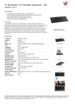
2.7
Printer
The VAS 5051B is delivered with an OKI B4350 printer (OKI Microline 22L for Japan) as
standard. Printers from the VAS 5051 can also still be used. Furthermore, you can also
install additional USB and network printers.
The printer is used for printing out screen masks, measurement results, etc. It is loaded
with DIN A4 paper for the European version, and for the USA version with US letter
paper.
The printer is delivered with:
•
•
•
•
Mains cable
Toner cartridge (packaged separately)
Software installation instructions
Operating instructions
Operating Manual VAS 5051B Hardware V01.4 03/07
A5E00309945/014
All rights reserved.
2-32
Design and Mode of Operation
VAS 5051B
•
A CD-ROM with drivers and the operating manual as a PDF file
1
2
3
4
6
5
Fig. 2-25
Printer
1. Display
2. Key panel
3. Release button
4. Extension for the form feedout
5. Paper tray
6. On/Off switch
At the workshop trolleys from Fa. Knürr and Fa. Rawotec the printer is operated via the
USB interface. In case of a re-equipped workshop trolley VAS 5051, the previously used
IrDA interface continues to be used (refer also to /5/).
All information regarding start-up, operation, maintenance and troubleshooting of the
printer is contained in the enclosed documentation. The manual /6/ is on the driver CD.
You can call up the printer manual as follows:
1. Insert the CD labelled CD 2, Printer User Guide into the CD drive of a PC on which
Acrobat Reader has been installed.
2. The following mask now appears:
Operating Manual VAS 5051B Hardware V01.4 03/07
A5E00309945/014
All rights reserved.
2-33
Design and Mode of Operation
VAS 5051B
Fig. 2-26
Dialog box for language selection of the printer manual
If the window does not open automatically then start the file setup.exe manually from
the main directory of the CD-ROM.
3. Use the pull-down menu to move to "Please Select Your Language" and then select
your language.
4. The manual is now displayed.
Note
If the manual is not available on the CD in your language then please contact OKI
directly, for example, at their website www.oki.com.
Operating Manual VAS 5051B Hardware V01.4 03/07
A5E00309945/014
All rights reserved.
2-34
Design and Mode of Operation
VAS 5051B
2.8
Optional accessories
The following optional accessories can be obtained in addition to the normal scope of
delivery of the system (Section 2.1.1):
•
•
•
•
•
•
2.9
Diagnostic cable 3 m (VAS 5051B/2)
Diagnostic cable LT2 (VAS 5051B/3)
1800 A current pick-up (VAS 5051B/8)
OBD adapter cable (VAS 5052/16) for connecting vehicles from another source
Temperature sensor
Pressure sensors
Accessories that can be bought on the open market
The following commercially available components can be used:
•
•
•
Earphone with headset
USB printer (other printers can also be installed by the user – see /3/)
External storage device:
− USB memory – all models released by VW can be connected to the tester.
Alternative:
− A USB floppy disk drive (compatible models: Teac FD-05PUB, FD-05PUW) – You
can only use these USB floppy disk drives safely as the required software drivers
are available for these. Other USB floppy disk drives may require other drivers and
may therefore not work.
Regarding the external storage devices
You can use an external storage device as the output media instead of a printer and
store your outputs such as screenshots and diagnostic protocols, on the storage device.
These outputs can then be displayed and printed out from a PC (refer to /3/). You can
connect a USB memory stick or a USB floppy disk drive. If both media are connected at
the same time then the output is directed to the USB memory stick.
With the print function you can set the output medium and safely remove a removable
data carrier.
Operating Manual VAS 5051B Hardware V01.4 03/07
A5E00309945/014
All rights reserved.
2-35
Operation
VAS 5051B
3
Operation
This chapter describes the operation of the VAS 5051B hardware . Operation of the
masks displayed on the tester is described in Operating Manual, VAS 505x "Software", /
3/.
3.1
Tester
3.1.1
Powering up the tester
Switch on the tester by pressing the On/Off button on the front panel of the tester (see
Fig. 3-1) or by connecting the tester to the vehicle’s on-board electrical system via the
diagnostic cable (only when the vehicle battery is sufficiently charged).
Fig. 3-1
Position of the On/Off button at the tester
The tester then starts up. In this phase, "VAS 5051B" appears for a short time on the
touch screen.
The tester is ready for operation when the message regarding the change of the station’s
name (if this has not yet been carried out) and the safety instructions are confirmed and
the ➚start mask is displayed (see /3/).
However, if a new ’base CD’ has previously been installed (complete with formatting)
then the screen must first be calibrated. More information on this is contained in /3/.
Note
Do not attempt to operate the tester during startup.
If the tester is connected to your LAN workshop network, it will automatically carry out a
➚net update during startup after being switched on.
Operating Manual VAS 5051B Hardware V01.4 03/07 All rights reserved.
A5E00309945/014
3-1
Operation
VAS 5051B
If the expiry date of the installed ➚’base CD’ has passed, the following message will
appear during startup:
The expiry date of the installed software
version <version number>
has passed.
Please install current base CD.
The tester can be used even though the expiry date has passed.
3.1.2
Touch Screen
The entire touch-sensitive surface of the screen is the touch screen. It reacts to the touch
of human fingers or of the touch pen and thereby replaces the normal functions of a
mouse or keyboard. You can execute any available programme function simply by
tapping the corresponding point on the screen.
Note
The screen reacts to all types of touch. When using the tester, make sure that it is
protected from unintentional touching by other devices or by persons.
Caution!
Do not use pointed or hot objects or drawing utensils to operate the touch screen. Doing
so can damage the touch screen.
Selecting
To ➚select an element of the display (text or button), you must tap the corresponding
point on the screen. The selected element will be highlighted. You will see its colour
change. Text items turn white and are marked with a black ➚selection bar; buttons turn
dark grey (see /3/). As long as you are touching the screen you can change the current
selection by moving the touch target. If you stop touching the screen then the selected
element is activated.
Operating Manual VAS 5051B Hardware V01.4 03/07 All rights reserved.
A5E00309945/014
3-2
Operation
VAS 5051B
3.1.3
Switching off the tester
Switch off the tester by pressing the On/Off button again (Fig. 3-1). Switch-off is
complete when the touch screen blanks out.
For switching off, refer also to Section 2.2.2.1.
3.1.4
Using the tester as a table unit
If you are using the tester as a table unit then completely flap open the standing leg. The
hinge must be pressed down manually until it snaps into place. This ensures that the
tester can be set in a stable manner into its slanting position.
3.1.5
Interfaces
Most of the interfaces are easily accessible behind a protective cap. To adapt a USB
cable, for example, pull the appropriate protective cap (see Fig. 2-5) to the side.
The PCMCIA interfaces are not freely accessible; they are located under the protective
cap at the top right (see Fig. 2-7, 4). The window on the rear allows you to monitor the
control LEDs on the PCMCIA card.
To install PCMCIA cards, proceed as follows:
1. Remove both screws on the corner piece to the right (see Fig. 3-2, 1) using a T8 Torx
screwdriver.
2. Remove the protective cap.
3. The PCMCIA slots can now be accessed (Fig. 3-2, 2); insert the expansion card.
4. Replace the protective cap. Caution: Do not turn the screws too tightly.
1
2
Fig. 3-2
1
Accessing the PCMCIA interfaces
Operating Manual VAS 5051B Hardware V01.4 03/07 All rights reserved.
A5E00309945/014
3-3
Operation
VAS 5051B
3.2
Workshop Trolley
The workshop trolley is used for mobile use of the tester in the workshop. It is mounted
on four rollers to allow it to be easily pushed within the working environment.
Depending on the design of the system, one of the following is used:
Fa. Knürr workshop trolley
•
Fa. Rawotec workshop trolley
•
a re-equipped VAS 5051 workshop trolley (for operation, refer to /5/)
All workshop trolleys are equipped with a dust-protective cover. It can be folded together
during operation and stored in the storage compartment of the workshop trolley.
•
Note
When the VAS 5051B is not in use, the mains connector should be pulled and the dustprotective cover should always be pulled over the workshop trolley.
Mobility
Both front wheels of the workshop trolley have been equipped with brakes to allow it to
be fixed at its location.
Release the brakes to move the trolley. You can push or pull the trolley to its new location
using the grips on the front and rear. You can then lock the brakes at the new location.
You can change your work location when the tester is switched on as long as there is
sufficient charge remaining in the battery. Disconnect the mains cable from the mains
and re-establish the power supply at the new workplace.
You can also disconnect the tester from the table power adapter when switched on in
order, e.g. to take the tester into the vehicle. Open the lock at the handle and remove the
tester from the tester mount. As soon as the tester is connected via the diagnostic cable
to an vehicles’ on-board electrical system with sufficient power, it will be supplied with
power from the vehicle's battery. Observe LED 1. It changes to green or yellow when
power is supplied from the vehicle.
Operating Manual VAS 5051B Hardware V01.4 03/07 All rights reserved.
A5E00309945/014
3-4
Operation
VAS 5051B
Ergonomics
There is a hinged cable arm to allow you to put down the diagnostic and measurement
cables ergonomically. Additionally, there is a holding fixture for looped cable to the rear of
the Knürr workshop trolley.
You can change the angle of inclination of the tester and its mount on the workshop
trolley from Fa. Rawotec and on the re-equipped VAS 5051 workshop trolley. This allows
you to adjust them ergonomically to the various working positions.
To change the angle of inclination at the Fa. Rawotec workshop trolley:
1. Grip the tester mount from below at the front and pull it up. You can clearly hear when
the mount snaps into its various positions.
2. After you have set the required angle, you must replace the keyboard mount into its
horizontal position. To do this, pull on the lock on the right side of the tester mount.
If you place the tester mount into its highest position then the locking mechanism releases
and the mount can once more be placed in its vertical position.
How to change the angle of inclination at the re-equipped VAS 5051 workshop trolley:
1. Grip the tester from above and below and swing it along the horizontal axis.
3.2.1
Using the tester without a workshop trolley
The tester has been designed for preferred use with the delivered workshop trolley. If the
tester is required during test drives then please observe the following:
Warning!
During test drives, secure the tester with a strap on the vehicle's back seat and connect
it to the vehicle using the diagnostic cable. A second person must operate the tester
from the back seat. Operation from the front seat is too dangerous, e.g. in the event of
airbag activation.
Operating Manual VAS 5051B Hardware V01.4 03/07 All rights reserved.
A5E00309945/014
3-5
Operation
VAS 5051B
3.3
Diagnostic and measurement cables
Diagnostic and measurement cable connections are coded by colour and mechanically.
The cable bushing matches the colour of the sockets. The mechanical coding requires
that the red point of the connector is aligned with the red point at the plug when
establishing a connection. The plugs can easily be inserted into the sockets without
using much pressure when so aligned.
Only grip the
plug bushing.
The red dot
leader points
forwards.
Fig. 3-3
Correct handling of a plug at the tester
To disconnect a plug from the tester, pull the locking collar of the plug upwards, thereby
also pulling the plug from the socket.
Note
The plugs are not threaded and turning them with force may damage them (see Fig. 3-3).
Operating Manual VAS 5051B Hardware V01.4 03/07 All rights reserved.
A5E00309945/014
3-6
Operation
VAS 5051B
3.3.1
OBD adapter cable (VAS 5052/16) for non-VW vehicles
To connect non-VW vehicles, always connect the adapter cable between the diagnostic
cable and the vehicle.
Caution!
The VAS 505x diagnostic devices were developed for vehicles from the Volkswagen
group. If the tester is connected directly to vehicles from other manufacturers, damage
to the vehicle could result.
Therefore if vehicles of other makes are to be tested using the general OBD functions in
the self-diagnosis application, the OBD adapter cable VAS 5052/16 needs to be
connected between the diagnostic cable and the diagnostic connection on the vehicle
(with fewer cable connections).
3.4
Printer
The OKI B4350 LED printer is used for printing out screen masks, measurement results,
etc. It is loaded with DIN A4 paper for the European version, and for the USA version
with US letter paper.
The OKI Microline 22L printer is used in Japan.
Details on how to operate the printer are contained in /6/.
Operating Manual VAS 5051B Hardware V01.4 03/07 All rights reserved.
A5E00309945/014
3-7
Troubleshooting
VAS 5051B
4
Troubleshooting
The VAS 5051B has been fully tested before being dispatched from the factory. Carefully
chosen components and adherence to numerous quality controls guarantee high
reliability for the VAS 5051B. However, if a problem does occur then please read the
instructions in this chapter before contacting the appropriate customer service (see /4/).
4.1
Classification
Faults that can occur at the VAS 5051B can be divided into the following:
Faults caused by environmental conditions: Environmental temperature, (aggressive)
humidity/damp, dust, soot, grease, flying sparks, mains, transformers, large engines,
radio communication systems, vibration
•
Faults at the VAS 5051B: tester, battery, workshop trolley, mains distribution at the
workshop trolley, diagnostic and measurement cables, printer, interfaces
Please try to determine what the fault is and to locate it as exactly as possible. Follow the
suggestions for solving the problem and carry out all measures suggested when
possible.
•
If the fault can not be remedied by the measures provided here then follow the instructions
in Section 4.4
Operating Manual VAS 5051B Hardware V01.4 03/07
A5E00309945/014
All rights reserved.
4-1
Troubleshooting
VAS 5051B
4.2
Self-test
The self-test sequence is described in the Operating manual VAS 505x, "Software",
Chapter "Administration".
4.2.1
Self-test of the test instruments and the diagnostic bus unit
If there are problems with test instruments or the diagnostic bus then the self-test
available in the Administration should always be carried out.
If you receive fault reports after this self-test, please contact Customer Service.
See Section 4.4.
4.2.2
Self-test of the online connection
If there are problems with the connection to the Workshop network, you should perform
the self-test in the administration/network settings. See /3/.
If you receive fault reports after this self-test, please contact your local IS consultant
(information system consultant).
Operating Manual VAS 5051B Hardware V01.4 03/07
A5E00309945/014
All rights reserved.
4-2
Troubleshooting
VAS 5051B
4.3
Symptoms, Causes and Solutions
4.3.1
Tester
Table 4-1
Possible fault characteristics
Symptom
Possible causes
Remedy
The system "stops
responding". The touch
screen can not be
operated.
Internal fault.
Switch the tester off and back
on again.
The cursor does not follow
the touching of the screen,
or does so imprecisely.
The screen is not
calibrated or screen
calibration was
incorrect.
Carry out a ➚screen
calibration.
The tester does not start or
starts in battery mode
(LED1 lights up orange).
The power supply has
been interrupted.
Make sure that the table power
adapter is correctly connected.
The tester does not start
and the LEDs do not light
up in spite of there being a
correct power supply.
The battery has
completely drained.
Charge the battery.
LED 1 flashes green and
orange alternately.
The battery is
defective or has been
removed.
Make sure that the battery
connection cable is correctly
connected.
When necessary, replace the
battery according to
Section 5.2.3.
LED 3 flashes red. The
tester switches off after
approx. 10 s.
There has been an
overtemperature in the
tester during
operation.
Allow the tester to cool down. If
LED 3 lights up when the
device is within the normal
temperature range, then
please send a fault report fax.
Operating Manual VAS 5051B Hardware V01.4 03/07
A5E00309945/014
If the device can no longer be
operated using the touch
screen then re-install the ’base
CD’, see /3/.
All rights reserved.
4-3
Troubleshooting
VAS 5051B
Table 4-1
Possible fault characteristics
Symptom
Battery mode does not
function.
Possible causes
The battery or the
charging circuit is
defective.
Remedy
Check whether the load
indicator (LED 2) is still lit. If it
indicates that there is only a
short charging time remaining
and the power of the battery
has dropped recently then the
battery may be used up.
Maintain the battery in
accordance with /3/.
When necessary, replace the
battery according to
Section 5.2.3.
Battery is flat
- Acknowledge the message.
- Connect the workshop trolley
to the mains and establish the
power connection for the tester
via the DC connection to
charge the battery.
Error message Fatal
Error.
System error
Switch the tester off and
attempt a re-start. If you
continue to receive this error
message, then please send a
fault report fax.
Error message No replaceable drive found, ...
External storage
device not connected
or connected
incorrectly.
Check the connection of the
USB memory or of the USB
disk drive.
•
Message Low Battery
You should change
your battery or switch
to outlet power
immediately to keep
from losing your
work.
Operating Manual VAS 5051B Hardware V01.4 03/07
A5E00309945/014
All rights reserved.
4-4
Troubleshooting
VAS 5051B
4.3.2
Diagnostic bus, diagnostic cable
Note
The function tests of the diagnostic cable and the diagnostic adapter described in the
following may only be carried out on vehicles free of defects to ensure that the test
delivers usable results.
If you discover a defect or if the relevant cable does not function even though the test
was performed with the result OK, please contact customer service.
4.3.2.1
Diagnostic cable
Table 4-2
Error messages at the diagnostic cable
Fault report
Error message
diagnostic bus faulty.
Possible causes
Remedy
Diagnostic cable not
connected correctly at the
tester or the vehicle.
Check the connections of the
diagnostic cable at the vehicle
and the tester.
Diagnostic bus or cable is
faulty.
Carry out a self-test on the
diagnostic bus.
Operating Manual VAS 5051B Hardware V01.4 03/07
A5E00309945/014
All rights reserved.
4-5
Troubleshooting
VAS 5051B
4.3.2.2
Diagnostic adapter (for older vehicles)
Carry out a function test of the diagnostic adapter (Section 2.5.2) as follows. If the test
results do not match the required values then there is a fault in the diagnostic adapter. In
this case, please submit a fault report in accordance to Section 4.4.
1. Connect the tester to the vehicle using a fully functional diagnostic cable and
diagnostic adapter. Switch on the ignition.
2. Switch-over to the Vehicle Self-Diagnosis operating mode and select the "Engine
Electronics" vehicle system (see /3/).
3. If the circuits are functional then information regarding the type of vehicle system is
displayed in the right part of the mask after a few seconds.
If the K or the L circuit is interrupted then the following message is displayed on the
top left of the window:
Vehicle system not available.
If the power supply line in the diagnostic adapter is interrupted then the following
message appears:
No voltage or voltage too low on diagnostic bus.
4.3.2.3
Diagnostic cable LT2
Carry out a function test of the diagnostic cable LT2 as follows. If the test results do not
match the required values then there is a fault in the diagnostic cable LT2. In this case,
please submit a fault report in accordance to Section 4.4.
1. Connect the tester to a vehicle via the diagnostic cable LT2.
2. Switch-over to the Vehicle Self-Diagnosis operating mode and select the "Engine
Electronics" vehicle system (see /3/).
3. Switch on the ignition. If the circuits are functional then information regarding the type
of vehicle system is displayed in the right part of the mask after a few seconds.
If the K or the L circuit is interrupted then the following message is displayed on the
top left of the window:
Vehicle system not available
If the power supply line in the diagnostic cable LT2 is interrupted then the following
message appears:
No voltage or voltage too low on diagnostic bus.
Operating Manual VAS 5051B Hardware V01.4 03/07
A5E00309945/014
All rights reserved.
4-6
Troubleshooting
VAS 5051B
4.3.3
Test instruments
The test instruments are comprised of the test instrument board and the connected
measurement cables. However, the self-test in the tester that can be called up for the
test instruments does not include the measurement cables. This must be checked by
means of comparative measurement if necessary.
Before starting to test the measurement cables, you should carry out a self-test on the
test instrument unit in order to exclude that it is faulty. See /3/.
The test instruments can also display messages regarding measurement faults
independently. The following table shows an example:
Table 4-3
Fault report of the test Instruments
Symptom
When measuring the
resistance and the
continuity, the following
error message appears:
Measurement error:
external power supply.
4.3.3.1
Possible causes
The component to be
tested is live.
Remedy
Switch off the external power
supply.
Test instrument unit
The test instrument unit is tested by the self-test that is built into the tester. In case of an
error, a fault number appears in the work window: If "OK" is shown in the window then
the test instrument unit is OK.
If the test instrument unit produces a fault report then you should make a screenshot for
later proof.
4.3.3.2
Measurement cables
U/R/D/I measurement cable
A function test of the U/R/D/I measurement cable is carried out as follows. If the test
results do not match the required values then there is a fault in the corresponding
U/R/D/I measurement cable. In this case, please submit a fault report in accordance to
Section 4.4.
Operating Manual VAS 5051B Hardware V01.4 03/07
A5E00309945/014
All rights reserved.
4-7
Troubleshooting
VAS 5051B
The U/R/D/I measurement cable is best checked using a comparative measurement.
Check the "voltage measurement" function, e.g. by connecting the leads to a vehicle
battery.
In the "resistance measurement" function, simulate an "open circuit" (Display: +++++ MΩ)
and "short-circuit" (near the display of 0.000 kΩ). You can also measure known resistances, e. g. of a relay coil (normally approx. 90 Ω).
When checking the diodes, you can also simulate an "open circuit" and "short-circuit".
However, a diode is required for additional tests. Check whether the appropriate symbols
(see /3/, Chapter Test Instruments) are displayed.
To check the "➚ inline current measurement" function you must use a circuit of max. 2 A.
DSO measurement cables
Carry out a function test of the DSO measurement cables as follows. If the test results do
not match the required values then there is a fault in the corresponding DSO
measurement cable. In this case, please submit a fault report in accordance to
Section 4.4.
1. Connect a DSO measurement cable to the DSO1 socket.
2. Press the Voltage DSO1 button in Test Instruments operating mode, Multimeter
mask. Select DC voltage as the type of measurement and the automatic range
selection.
3. Connect the measuring tips of the DSO measuring cable with a charged car battery..
The measurement value that is displayed must be the same as the battery voltage
(between 11 and 14 V).
4. Check the freeze image selection by pressing the button on the red/black probe tip.
The measurement value is frozen, the "freeze frame" button must appear to be
pressed on the screen.
Carry out a comparative measurement between U/R/D/I and DSO:
1. Release the freeze frame by pressing the button again in order to continue the
measurement.
2. Additionally connect the U/R/D/I measurement cable to the tester and the vehicle
battery. Its correct functioning should have been checked before connecting it.
3. Press the Voltage U/R/D button. Select DC voltage as the type of measurement and
the automatic range selection.
4. In both displayed measurement functions (DSO1 and U/R/D), the difference in the
measured values must be ≤ 0.2 V.
Operating Manual VAS 5051B Hardware V01.4 03/07
A5E00309945/014
All rights reserved.
4-8
Troubleshooting
VAS 5051B
Repeat the function test with the second DSO measurement cable.
Note
Both DSO measurement cables are identical and can be exchanged for testing.
Current pick-ups
Carry out a function test of the current pick-ups as follows. If the test results do not match
the required values then there is a fault in the current pick-up. In this case, please submit
a fault report in accordance to Section 4.4.
1. Connect a current pick-up to the tester.
2. Press the Current pick-up button in Test Instruments, mask Multimeter. The current
pick-up must be automatically recognized. Select DC current as the type of
measurement and the automatic range selection.
3. Open and close the current pick-up several times without connecting it to a live cable.
The value measured must change considerably between these two states (open and
closed). In case of the 100 A pick-up, check whether the LED at the current pick-up
correctly displays the conditions "opened (LED is on) / closed (LED is off)".
Now check the calibration of the current pick-up:
1. Press the Calibrate button on the screen. Close the message displayed by pressing
the OK button. At most, the measured value displayed after calibration must equal the
tolerance in the lowest measurement range (see Section 6.3.1).
2. Connect the current pick-up to a battery cable or another cable of a consumer in a
vehicle. All consumers and the ignition of the vehicle should be switched off at first.
The displayed measurement result should only change marginally (environmental
influences).
How to perform a comparative measurement:
1. Switch on a consumer, e.g. the parking light. The power consumption should be
known as accurately as possible. Take this value as a starting point. The measured
value should be the same as this value.
2. Pull the current pick-up from the cable carrying the current and plug it back in,
reversed by 180°. The difference must remain within the stipulated tolerance (see
Section 6.3.1).
Operating Manual VAS 5051B Hardware V01.4 03/07
A5E00309945/014
All rights reserved.
4-9
Troubleshooting
VAS 5051B
Trigger clamp and kV pick-up
The trigger clamp and kV pick-up can only be tested together. Carry out a function test
as follows. If the test results do not match the required values then there is a fault in one
of the sensors. In this case, please submit a fault report in accordance with Section 4.4.
1. Connect the trigger clamp and the kV pick-up to the tester.
2. Call up the DSO mask in operating mode Test Instruments, (see /3/).
3. Connect both pick-ups via the same ignition cable (secondary side of the ignition coil)
to a vehicle with a 4 or 6 cylinder engine.
4. Press the Preset measurement button in the DSO mask, select the Secondary ignition
voltage curve in the selection list that appears, and confirm with the Display button.
The DSO mask will appear with the set curve in the background. At the same time, all
DSO settings will be made automatically.
5. Start the vehicle's engine. The typical ignition signal must be displayed dynamically,
i.e. the picture is re-written once or twice per second if the kV pick-up and trigger
clamp are working correctly.
If the trigger clamp is faulty then the following message appears in the window at the top
right:
No trigger
If the kV pick-up is faulty then a horizontal line may only be displayed or else a signal
curve with much too small an amplitude.
Note
Depending on the type of vehicle used, the amplitude of the ignition signal may
fluctuate between 4 and 40 kV. The combustion voltage is normally between 600 and
1200 V, and the combustion duration should be between 1 and 6 ms. The shape of the
curve may vary depending on the manufacturer of the ignition coil.
Operating Manual VAS 5051B Hardware V01.4 03/07
A5E00309945/014
All rights reserved.
4-10
Troubleshooting
VAS 5051B
4.3.4
The printer
If the output at the printer is faulty or the printer does not print then check the text output
at the display. Check
whether the printer is switched on and/or is online
•
whether there is paper in the printer
•
whether there is a paper jam in the printer
•
whether the connection to the tester is interrupted
•
whether the output medium at the tester is set correctly ("Print", menu, "Select output
medium" – see /3/)
•
whether the printer driver/paper format is set correctly (under "Administration - Printer
Settings" – see /3/)
If the printer still does not print or the print-out is faulty then consult /6/.
•
When operating the printer via the IrDA adapter of the VAS 5051 workshop trolley, the
following message may be displayed from time to time:
Fig. 4-1
Message from printer driver
This message appears when the print job cannot be processed immediately. This
message disappears automatically when the print job can be processed. The meanings
of the acknowledgement buttons are:
"Retry": repeat the print job
"Cancel": delete the print job
4.4
Fault Reports to Customer Service
If the fault that has occurred cannot be remedied then please consult the customer
service. Fur further information see /4/.
Operating Manual VAS 5051B Hardware V01.4 03/07
A5E00309945/014
All rights reserved.
4-11
Troubleshooting
VAS 5051B
4.5
Replacement Parts and Accessories
4.5.1
Overview
During the guarantee period, repairs to the VAS 5051B are made by replacing defined
components. In case of submitting a fault report to your appropriate customer service
you will be informed which components will be replaced under guarantee conditions. You
will then receive one or more replacement parts on the instigation of the guarantor.
These parts are divided into exchange parts, replacement parts and repair parts.
Exchange parts: Some components of the VAS 5051B are exchange parts that you
must return in exchange for a new or repaired component. You will be told the address
to send the defective exchange parts to as required. The components sent can also
be replaced by a repaired exchange part. You have no claim to receive new parts.
•
Replacement parts: You can dispose of replacement parts yourself. Please observe
your national regulations on the disposal of such parts.
•
Repair parts: Send repair parts to the supplier. After the repairs your components/
parts will be returned to you and you can install them yourself.
Section 4.5.3 lists all parts and informs you of whether a particular part is an exchange
part, a replacement part or a repair part.
•
In certain cases, the guarantor may also demand that you return components that are not
normally exchange parts.
4.5.2
General notes
Tester
If the tester (without accessories) must be replaced then you will receive a replacement
device in a box that you should also use to send back your defective device. Return
complete tester after removing the accessories (Remove battery, table power adapter
and any PCMCIA cards you may have inserted).
Cables
Defective diagnostics and measurement cables are replaced completely. If the mains
cable has to be replaced, then observe the technical data in accordance to Section 6.5
and the assembly instructions (see the start-up instructions).
Operating Manual VAS 5051B Hardware V01.4 03/07
A5E00309945/014
All rights reserved.
4-12
Troubleshooting
VAS 5051B
Battery
Replace the battery in accordance with Section 5.2.3.
USB cable (only for workshop trolley VAS 5051B)
The cable connects the printer to the tester.
1. Check whether the cable is connected to the tester and the printer.
2. Check whether the cable is damaged. If it is damaged, then replace the 1.8 m
USB cable.
IrDA Adapter (only for the VAS 5051 workshop trolley)
The IrDA adapter cable is attached to the workshop trolley with a cable relief that is not
part of the delivery of the exchange part.
1. Pull the IrDA adapter towards the open side of its mount from the workshop trolley.
2. Pull the cable at the workshop trolley from the guide of the side boom (keep the rubber
parts safely for future use).
3. Remove the round plastic lid from the sidewall behind the boom to the right of the
trolley.
4. Release the centronics plug from the printer.
5. Release the cable relief and remove the IrDA adapter.
Mount the new IrDA adapter by reversing the order of steps 1 - 5 in the above.
Workshop Trolley
To obtain spare parts for the VAS 5051B workshop trolley, please contact the
manufacturer (Fa. Knürr, Fa. Rawotec, see /4/).
For spare parts for the re-equipped VAS 5051 workshop trolley see /5/. For new tester
mounts, please contact Fa. Knürr.
Operating Manual VAS 5051B Hardware V01.4 03/07
A5E00309945/014
All rights reserved.
4-13
Troubleshooting
VAS 5051B
4.5.3
Parts List for the VAS 5051B
The following types can be delivered:
System delivery with workshop trolley VAS 5051B, models:
Fa. Knürr
Fa. Rawotec
•
•
Re-equipped VAS 5051 incl.
Fa. Knürr tester mount for the VAS 5051 workshop trolley
Table 4-4
Symbols and Abbreviations
Symbol
Meaning
ID
Meaning
Part of the system
delivery
A
exchange part
❍
Accessories
E
replacement part
Can be taken over
when re-equipping
the VAS 5051
R
repair part
Type
Supplier
Comments
VW number
Model
VAS No.
Identification
System
delivery
No.
Manufacturer's
number
●
Reequipping
•
●
Operating Manual VAS 5051B Hardware V01.4 03/07
A5E00309945/014
A
’Base CD’ preinstalled
SIEMENS
●
A5E00262287
Tester
VAS 5051B/13
1
ASE40528200000
Tester
All rights reserved.
4-14
Troubleshooting
4
Battery pack,
lithium ion,
14.8 V
●
Type
Supplier
VW number
A5E0088672
E
A5E00145150
5051B/14
●
SIEMENS
●
E
SIEMENS
Mains cable,
for table power
adapter, type
US, 3 m
Without mains
cable
SIEMENS
3b
E
E
SIEMENS
●
ASE40528700000
Mains cable,
for table power
adapter, type
EU, 3 m
Comments
ASE40528200000
3a
●
A5E00297492
●
A5E00262564
Table power
adapter
5051B/17
2
VAS No.
Model
Reequipping
Identification
System
delivery
No.
Manufacturer's
number
VAS 5051B
Fan with cable
Operating Manual VAS 5051B Hardware V01.4 03/07
A5E00309945/014
E
2 pieces
SIEMENS
5
A5E00262556
Tester,
small parts
All rights reserved.
4-15
Troubleshooting
5052/11
3, as spare
parts
Operating Manual VAS 5051B Hardware V01.4 03/07
A5E00309945/014
Type
Supplier
VW number
SIEMENS
E
Top handle
E
For operating the
screen
SIEMENS
Touch pens
Rubber covers
over interfaces
SIEMENS
9
E
SIEMENS
Coated insert
handle
ASE40517500000
8
A5E00295901
Set of covers
incl. fixing
strips and
screws
E
A5E00343305
7
Comments
A5E00273602
Set of corner
pieces
(2 x corner
piece 1,
(1 x corner
piece 2,
1 x cover of
wireless card)
A5E00133742
6
VAS No.
Model
Reequipping
Identification
System
delivery
No.
Manufacturer's
number
VAS 5051B
All rights reserved.
4-16
Troubleshooting
Type
Supplier
Comments
VW number
VAS No.
Model
Reequipping
Identification
System
delivery
No.
Manufacturer's
number
VAS 5051B
13
Test adapter
cable
●
5051B/2
5051B/3
A5E00314690
5051B/4
●
Operating Manual VAS 5051B Hardware V01.4 03/07
A5E00309945/014
SIEMENS
❍
No technical
difference to the
5 m diagnostic
cable
E
For commercial
vehicle systems
LT2
E
for the self-test
Diagnostic bus
SIEMENS
Diagnostic
cable LT2
E
SIEMENS
12
E
SIEMENS
❍
ASE40527000000
❍
ASE40527100000
3 m diagnostic
cable
ASE40527200000
11
ASE40527300000
●
A5E00328205
●
A5E00310809
5 m diagnostic
cable
5051B/1
10
A5E00276114
Diagnostic
and measurement cables
All rights reserved.
4-17
Troubleshooting
●
●
18
Replacement
test probe tips
for U/R/D/I and
DSO cable for
red/black test
probes
●
●
A5E00328217
A5E00276115
A5E00262596
VAS 5052/16
5051B/5
5051B/6
5051B/17
Operating Manual VAS 5051B Hardware V01.4 03/07
A5E00309945/014
Type
VW number
Supplier
SIEMENS
DSO measurement cable
(1 piece)
For connecting
vehicles from
another source
VW
17
E
E
SIEMENS
●
For older vehicle
systems
E
2 delivered with
the system,
1, as spare part
E
5 pieces,
with screw-in
thread
SIEMENS
●
E
SIEMENS
U/R/D/I
measurement cable
ASE40556000000
16
ASE40518200000
❍
ASE40527400000
OBD adapter
cable
ASE40527500000
15
Comments
ASE40528600000
●
C79298-A3238-B505
Diagnostic
adapter
5051/2
14
VAS No.
Model
Reequipping
Identification
System
delivery
No.
Manufacturer's
number
VAS 5051B
All rights reserved.
4-18
Troubleshooting
VAS 5051B
23
Temperature
sensor
❍
❍
5051/70
5051/18
●
Operating Manual VAS 5051B Hardware V01.4 03/07
A5E00309945/014
Type
Supplier
SIEMENS
SIEMENS
SIEMENS
ASE40506300000
E
E
For triggering the
DSO
SIEMENS
ASE40527600000
ASE40527700000
Trigger clamp
E
For measuring
ignition voltages
VW
22
ASE40506400000
5051/17
●
VW number
Manufacturer's
number
A5E00276116
A5E00328211
kV pick-up
C79298-A3238-B535
VAS No.
VAS 5051B/7
❍
1800 A current
pick-up
C79298-A3238-B540
21
●
50 A can be used
20
100 A current
pick-up
500 A can be used
19
Comments
5051B/8
Model
Reequipping
Identification
System
delivery
No.
E
E
All rights reserved.
4-19
Troubleshooting
26
Pressure
sensor
0 to 60 bar
❍
❍
27
Pressure
sensor
0 to 400 bar
❍
❍
Type
Supplier
VW number
VW
❍
E
VW
❍
E
VW
Pressure
sensor
-1 to 4 bar
E
VW
25
Comments
E
5051/58
❍
5051/59
❍
5051/60
Pressure
sensor
-1 to 1 bar
5051/61
24
VAS No.
Model
Reequipping
Identification
System
delivery
No.
Manufacturer's
number
VAS 5051B
●
28c
UK mains
cable
(Type C) 6 m
●
Operating Manual VAS 5051B Hardware V01.4 03/07
A5E00309945/014
E
Mostly in
North America and
Central America
E
Mostly in
Great Britain
SIEMENS
US mains
cable
(Type B) 6 m,
oil-resistant
Mostly in Europe
SIEMENS
28b
E
SIEMENS
●
A5E00328614
EU mains
cable
(Type A) 6 m
A5E00328615
28a
A5E000328613
Mains cable
and distributor, workshop
trolley
All rights reserved.
4-20
Troubleshooting
28i
BR mains
cable
(Type B2) 6 m
●
Operating Manual VAS 5051B Hardware V01.4 03/07
A5E00309945/014
Type
●
Supplier
CN mains
cable
(Type L) 6 m
Switzerland
E
Israel
E
China
E
Brazil
SIEMENS
28h
E
SIEMENS
●
Mostly in Australia
and New Zealand
SIEMENS
IL mains cable
(Type I) 6 m
E
SIEMENS
28g
Mostly in West
South Africa and
Namibia
SIEMENS
●
E
SIEMENS
CH mains
cable
(Type H) 6 m
Comments
VW number
28f
A5E00328616
●
A5E00328617
Mains cable
(Type F) 6 m
A5E00328618
28e
A5E00328619
●
A5E00328620
AF mains cable
(Type D) 6 m
A5E00342908
28d
VAS No.
Model
Reequipping
Identification
System
delivery
No.
Manufacturer's
number
VAS 5051B
All rights reserved.
4-21
Troubleshooting
●
29b
US power
outlet strip
●
Type
EU power
outlet strip
Supplier
29a
E
Fa. Knürr Fa. Knürr SIEMENS
●
VW number
J mains cable
(Type B3) 6 m
Comments
A5E00342909
28j
VAS No.
Model
Reequipping
Identification
System
delivery
No.
Manufacturer's
number
VAS 5051B
Japan
A
A
Printer
OKI Microline
22L, Japan
version
●
Operating Manual VAS 5051B Hardware V01.4 03/07
A5E00309945/014
A
Printer, 120-127 V
A
Printer, 100 V
VW
30c
Printer, 220-240 V
VW
●
A
VW
Printer
OKI B4350,
US-version
ASE 40507503000
30b
A5E00342951
●
A5E00343012
Printer
OKI B4350,
EU-version
VAS 5051/51A
30a
A5E00342949
Printer
All rights reserved.
4-22
Troubleshooting
Type
Supplier
VW number
SIEMENS
OKI/VW
OKI/VW
E
Fa. Knürr
ASE40507602000
Toner for
printers
OKI B4350
and B4300
Not required for reequipping the
VAS 5051
workshop trolley
E
ASE40507702000
33
E
ASE40527800000
Picture drum
unit for printers
OKI B4350 and
B4300
❍
Comments
A5E00273189
32
●
VAS 5051/52
USB cable
1.8 m
VAS 5051/53
31
VAS No.
Model
Reequipping
Identification
System
delivery
No.
Manufacturer's
number
VAS 5051B
Workshop
trolley
Workshop
trolley, Fa.
Knürr
5051B/9
34a
Operating Manual VAS 5051B Hardware V01.4 03/07
A5E00309945/014
All rights reserved.
4-23
Troubleshooting
Fa. Knürr
Fa. Rawotec
Type
Supplier
ASE40527900000
VW number
Comments
ASE40528000000
Workshop
trolley, Fa.
Rawotec
A5E00262594
34c
5051B/10
Single tester
mounts for reequipping of
the VAS 5051
workshop
trolley, Fa.
Knürr
5051B/11
34b
VAS No.
Model
Reequipping
Identification
System
delivery
No.
Manufacturer's
number
VAS 5051B
●
●
5051/B23
Operating Manual VAS 5051B Hardware V01.4 03/07
A5E00309945/014
American English
E
Italian
SIEMENS
Compact
Keyboard I
E
SIEMENS
35b
ASE40529200023
●
ASE40529200050
●
A5E00348257
Compact
keyboard US
5051/B23
35a
A5E00348261
USB keyboard
and
USB mouse
All rights reserved.
4-24
Troubleshooting
Optical power
wheel mouse
●
●
5051/B23
5051/B23
5051/B24
Operating Manual VAS 5051B Hardware V01.4 03/07
A5E00309945/014
Supplier
VW number
Type
Spanish
E
German
SIEMENS
36
E
SIEMENS
●
French
SIEMENS
●
E
E
SIEMENS
Compact
Keyboard D
ASE40529200040
35e
ASE40529200060
●
ASE40529300000
●
Comments
ASE40529200023
Compact
Keyboard E
A5E00348244
35d
A5E00348234
●
A5E00348227
●
A5E00348221
Compact
Keyboard F
5051/B23
35c
VAS No.
Model
Reequipping
Identification
System
delivery
No.
Manufacturer's
number
VAS 5051B
All rights reserved.
4-25
Troubleshooting
Type
Supplier
Comments
VW number
VAS No.
Model
Reequipping
Identification
System
delivery
No.
Manufacturer's
number
VAS 5051B
Documentation
●
●
40
Brief
instructions
(folding sheet)
●
●
SIEMENS
Operating
Manual, VAS
505x
"Software"
on the ’base CD’
A5E003300xx
language-specific
5051B/15
Operating Manual VAS 5051B Hardware V01.4 03/07
A5E00309945/014
SIEMENS
39
on the ’base CD’
SIEMENS
●
E
Printed version
SIEMENS
●
ASE40528500000
Operating
Manual, VAS
5051B
"Hardware"
ASE40528400000
38
E
A5E003090xx
language-specific
●
A5E003099xx
language-specific
●
A5E003299xx
language-specific
Start-up/
Unpacking
instructions
5051B/16
37
All rights reserved.
4-26
Care and Maintenance
VAS 5051B
5
Care and Maintenance
5.1
Optical check of the VAS 5051B
Carry out a regular optical check of the VAS 5051B. Examine all parts for damage
(e.g. breaks) and for dirt.
Check the touch screen for damage or dirt.
Regularly check the device, all cables and the accessories for damage.
Warning!
If the mains cable, a diagnostic or measurement cable, the tester or any accessory carrying live current is damaged, you must not use it until a properly qualified specialist has
investigated it and approved it.
5.2
Tester
If the housing is dirty then clean it with a lint-free, damp (not wet!) cloth.
Caution!
Before cleaning the tester, turn it off to ensure safety and pull out the DC supply plug.
Remove all measurement cables. Pay careful attention that no liquid enters into the
housing. Do not try to clean the insides of the DVD and disk drives.
Caution!
Do not overtighten the screws on the housing.
The housing of the tester is made of magnesium. Housing screws must therefore not be
screwed in too tightly (just as with aluminium). The build in screw theads may loosen
too. Take special care at the corner pieces.
Make sure that the venting slots to the left and right of the tester remain uncovered.
remove any dirt using a vacuum cleaner.
If the tester is damaged then please contact the SIEMENS hotline (see /4/).
Operating Manual VAS 5051B Hardware V01.4 03/07 All rights reserved.
A5E00309945/014
5-1
Care and Maintenance
VAS 5051B
5.2.1
Cleaning the touch screen
The most sensitive part of the tester is the touch screen. Its sensitivity to touch may be
impaired by dirt and by scratches. If it becomes dirty then clean it using a soft, non-lint
cloth. If the dirt can not be removed using the cloth then you can use isopropanol or an
ammonia-free glass cleaner.
5.2.2
Battery
The battery has a standard lifetime of approx. 500 charge/discharge cycles. It then has a
remaining capacity of approx. 50%.
Note
•
•
A lithium ion battery does not require formation.
The battery must be disposed of or recycled when completely discharged in accordance with the local regulations.
Caution!
•
•
•
•
The battery may only be replaced by trained personnel
Never short-circuit the battery
Never throw the battery into a fire
Dispose of or recycle the battery in accordance with the local regulations
Operating Manual VAS 5051B Hardware V01.4 03/07 All rights reserved.
A5E00309945/014
5-2
Care and Maintenance
VAS 5051B
Battery maintenance
Due to age, the usable capacity of the battery decreases and the amount of faults
increases when measuring the capacity for the charging circuit. To compensate for this
process, a calibration must be carried out from time to time for the battery control. The
required maintenance interval is automatically reported by the tester and serves the purpose of optimizing the usable capacity of the battery. Follow the instructions on the screen
(see /3/).
5.2.3
Replacing the battery
Caution!
Always replace a defective battery with a new battery. Never operate the device without
a battery as the installed operating system may be destroyed if the power supply is
interrupted.
You can find the order number and source of supply for the expendable part in the Parts
List for the VAS 5051B.
Replace the battery as follows:
1. Place the tester with the screen downwards on an even, clean surface.
2. Remove the four screws on the cover of the battery pack (see Fig. 2-7, 10). To do this,
use a T10 TORX screwdriver.
3. Flap up the support leg.
4. Lift the cover from below in the middle and remove it.
5. The battery is fixed by foam part. You can release the battery by pressing the foam
part upwards at the right, see Fig. 5-1.
Operating Manual VAS 5051B Hardware V01.4 03/07 All rights reserved.
A5E00309945/014
5-3
Care and Maintenance
VAS 5051B
Fig. 5-1
Replace the battery by removing it from the battery compartment
6. Disconnect the plug connection at the battery cable. Press the retaining springs in the
middle of both plug components downwards (using your thumbnails) and pull the plug
connection apart, see Fig. 5-2.
Press here
Fig. 5-2
Replacing the battery and releasing the plug connection at the battery cable
7. Replace the old battery with a new battery.
8. Re-connect the previously disconnected plug connection. The plug must snap into the
socket.
9. Reassemble all parts. Caution: Do not over-tighten the screws on the housing.
Operating Manual VAS 5051B Hardware V01.4 03/07 All rights reserved.
A5E00309945/014
5-4
Care and Maintenance
VAS 5051B
5.2.4
Replacing the fans
You can find the order number and source of supply for the expendable parts in the Parts
List for the VAS 5051B.
Replace both fans as follows:
Remove the fans:
1. Place the tester (switched off) with the screen flat down on an even, clean and cleared
surface to ensure that the screen cannot be damaged.
2. Remove the six screws on the cover of the battery pack (see Fig. 5-3). To do this, use
a T10 TORX screwdriver.
One of the six screws is underneath the standing leg. A recess allows you to remove
the screw without having to flap up the standing leg.
Fig. 5-3
3.
4.
5.
6.
Changing the fans, unscrewing the cover
Remove the top cover.
Pull the power cable from its position and disconnect both plug connections.
Now carefully pull both fans off their installation position.
Replace the fans.
Operating Manual VAS 5051B Hardware V01.4 03/07 All rights reserved.
A5E00309945/014
5-5
Care and Maintenance
VAS 5051B
Installing the fans:
7. Hold the sides of the two fans against each other.
8. Place them both simultaneously into their installation position (see Fig. 5-4).
9. Re-establish the plug connections and guide the cable through the recess intended
for this purpose (see Fig. 5-5).
10. Re-mount the cover onto the tester. Caution: Do not overtighten the screws on the
housing.
Fig. 5-4
Changing the fans, installing
Fig. 5-5
Changing the fans,
aying the cable
Operating Manual VAS 5051B Hardware V01.4 03/07 All rights reserved.
A5E00309945/014
5-6
Care and Maintenance
VAS 5051B
5.2.5
Replacing the corner pieces
To replace the corner pieces, proceed as follows:
1. Remove the screws at the rear of the corner pieces (see Fig. 5-6). To do this, use a
T8 TORX screwdriver. The right, upper corner piece is fixed by two screws at the top;
refer also to Section 3.1.5.
2. Grip the corner piece at the front and rear and carefully pull it upwards.
Caution!
The bluetooth antenna is located underneath the left, upper corner piece. Make sure
that it is not damaged during the procedure.
Fig. 5-6
Example: replacing the corner piece to the left
Installing:
3. Carefully insert the new corner piece and fix it using the screw(s).
Caution: Do not overtighten the screws on the housing.
Operating Manual VAS 5051B Hardware V01.4 03/07 All rights reserved.
A5E00309945/014
5-7
Care and Maintenance
VAS 5051B
5.3
Workshop Trolley
The workshop trolleys are maintenance-free.
5.4
Diagnostic and measurement cables
Regularly check all diagnostic and measurement cables for damage. Replace damaged
cables.
5.4.1
Changing the measuring tips on the red/black probe tip
1. Grasp the front part of the measuring tip with flat-nose pliers and turn the probe tip
until the part separates.
2. Insert the new test probe tip. The middle section of the test probe tip is hinge-mounted.
Only the tip at the plus leads (red/black test probes) can be replaced.
5.5
Printer
Maintenance of the printer is described in /6/.
5.6
Calibration
According to ISO regulations 9000 ff., the measurement accuracy of all measuring
equipment that influences the quality of the work carried out (in this case, maintenance
and repair work) must be periodically calibrated.
The tester and the measurement cables are calibrated for 3 years on delivery (see
Section 1.5). Thereafter, calibration must be repeated every two years.
Before this time has expired, please consult the contact person for the respective brand.
Operating Manual VAS 5051B Hardware V01.4 03/07 All rights reserved.
A5E00309945/014
5-8
Technical Specifications
VAS 5051B
6
Technical Specifications
6.1
VAS 5051B Tester
6.1.1
Operating Data
Dimensions (W x H x D)
approx. 410 x 310 x 95 mm
Weight
approx. 7.6 kg
Ambient conditions
Operation
Ambient temperature
Relative humidity
+5 to +40 °C
at max. +25 °C
10 to 80%,
non-condensing
-20 to +60 °C
at max. +20 °C
10 to 80%,
non-condensing
Transport and storage
Ambient temperature
Relative humidity
Electrical protection and
safety
Safety regulations
- Workshop devices: UL 201
- Devices for information processing:
DIN EN 60950 (VDE 0805), EN 60950, IEC 950,
UL 1950, CSA-C22.2 No. 950
- Testing devices: DIN EN 61010-1 (VDE 0411 Part 1),
EN 61010-1, IEC 1010-1
Protection class I (as per DIN EN 60950), relevant for
the table power adapter unit only
Protected from water and foreign objects as per
DIN VDE 0470 Part 1 (EN 60529, IEC 529)
- Degree of protection: IP 20
For company-internal use only
Pollution Degree II
Overvoltage category I
Power supply
Power is supplied by one of the following, depending
on the application:
- Table power adapter
- Battery
- Vehicle on-board electrical system
Operating Manual VAS 5051B Hardware V01.4 03/07 All rights reserved.
A5E00309945/014
6-1
Technical Specifications
VAS 5051B
Power supply from
table power adapter
Current consumption
DC 24 V, 5 A
Power supply
from the battery
If the external power supply (table power adapter,
mains, vehicle on-board electrical system) is interrupted, the tester is buffered with the battery.
Lithium ion, 14.8 V
Battery type
Buffer time
Recharging time
(at the mains)
Power supply from the
vehicles’ on-board electrical system
Rated voltages
Power consumption in the
load range
Protection
Usually 1 h (depending on operating mode, battery
state and the external consumers)
Approx. 2.5 h (only with table power adapter connected)
The tester can be supplied with power from the vehicle’s on-board electrical system
DC 12 V, DC 24 V
max. 5 A at 12 V battery voltage
The input is protected against disturbances acc. to
DIN 40839 Part 1, Test Impulses 1 to 4, Test Level IV.
The input is protected against reverse polarity.
Operating Manual VAS 5051B Hardware V01.4 03/07 All rights reserved.
A5E00309945/014
6-2
Technical Specifications
VAS 5051B
External interfaces,
wired
COM1 (V.24)
USB interface
Monitor (VGA)
Ethernet interface
Audio input
Audio output
Power output
Chip card reader
PCMCIA slot
DC input
9-pin sub-D plug for RS232/RS485
4 x USB standard 2.0
15-pin sub-HD plug
RJ45 socket
socket socket 3.5 mm
socket socket 3.5 mm
at 8 Ω load: 200 mW (at 0.1% distortion)
at 32 Ω load: 85 mW (at 0.1% distortion)
Smartcard as per ISO7816
for PCMCIA cards 1 x Type III or 2 x Type II
2-pin mini SNAP socket, size 2.
Socket panel
(test instruments)
DIAG
URDI
DSO1, DSO2
SZ
KV
TZ
T/D
Mini SNAP sockets
Diagnosis interface, 18-pin
Multimeter, 14-pin, size 3
Storage oscilloscope, 12-pin, size 2
Current pick-up, 8-pin, size 2
kV pick-up, 5-pin, size 1
Trigger pick-up, 5-pin, size 1
Temperature/pressure, 10-pin, size 2
External interfaces,
wireless
IrDA
Bluetooth
Infrared interface for the printer
Wireless interface for expansions
Operating Manual VAS 5051B Hardware V01.4 03/07 All rights reserved.
A5E00309945/014
6-3
Technical Specifications
VAS 5051B
6.2
Table power adapter
Table power adapter
The table power adapter supplies the tester from the
230 (110) V mains. The table power adapter is housed
in the workshop trolley.
Rated voltage range
Rated frequencies
AC 100 to 240 V
50 - 60 Hz
DC cable
The DC cable (approx. 1.2 m) is permanently connected to the table power adapter.
Mains cable (internal)
The power cable (approx. 3 m) is connected to the
mains network in the workshop trolley.
Inlet connector for non-heating apparatus, Type C13,
EN60320/C13
and for
Variant 1: Schuko plug, Type VII as per CEE(7) VII
Variant 2: USA plug, Type 498 G as per NEMA 5-15
Plug type
Operating Manual VAS 5051B Hardware V01.4 03/07 All rights reserved.
A5E00309945/014
6-4
Technical Specifications
VAS 5051B
6.3
Test Instruments
6.3.1
Multimeter
U/R/D/I multimeter measurement cable
Caution!
when using the U/R/D/I cable.
The U/R/D/I cable (with purple identification of the pin plug) is approved only for voltage
peaks up to 42 V and current measurements up to 2 A.
Change the cable to measure higher voltages/currents!
DC voltage at U/R/D/I
(Ri ≥ 1 MΩ)
Range
-2 to +2 V
-20 to +20 V
-50 to +50 V
Resolution
0.001 V
0.01 V
0.01 V
Tolerances
±0.5% of m1. ±2 mV
±0.5% of m. ±20 mV
±0.5% of m. ±50 mV
AC voltage
at U/R/D/I
(RMS,
50 Hz to 5 kHz,
Crest factor max. 3,
Ri ≥ 1 MΩ)
Range
Resolution
Tolerances
0 to 2 V
0 to 20 V
0 to 40 V
0.001 V
0.01 V
0.01 V
±1.5% of m. ±4 mV
±1.5% of m. ±40 mV
±1.5% of m. ±80 mV
AC voltage
at U/R/D/I
(RMS,
5 kHz to 10 kHz,
Crest factor max. 3,
Ri ≥ 1 MΩ)
Range
Resolution
Tolerances
0 to 2 V
0 to 20 V
0 to 40 V
0.001 V
0.01 V
0.01 V
±5% of m. ±4 mV
±5% of m. ±40 mV
±5% of m. ±80 mV
Direct inline current
(Ri ≤ 250 mΩ)
via U/R/D/I
measurement cable
Range
-0.2 to 0.2 A
-2 to 2 A
Resolution
0.0001 A
0.001 A
Tolerances
±1% of m. ±1 mA
±1% of m. ±10 mA
AC inline current
(RMS, 30 to 500 Hz,
crest factor max. 3,
Ri ≤ 250 mΩ)
via U/R/D/I
measurement cable
Range
0 to 0.2 A
0 to 2 A
Resolution
0.0001 A
0.001 A
Tolerances
±1.5% of m. ±1 mA
±1.5% of m. ±10 mA
1.) of measurement value
Operating Manual VAS 5051B Hardware V01.4 03/07 All rights reserved.
A5E00309945/014
6-5
Technical Specifications
VAS 5051B
Resistance
via U/R/D/I
measurement cable
The measuring current depends on the measurement
range and is 5 mA maximum.
Range
Resolution Tolerances2)
0 Ω to 10 Ω
10 mΩ
±1% of m. ±5 mΩ
0 Ω to 100 Ω 0.1 Ω
±1% of m. ±50 mΩ
0 Ω to 1 kΩ
1Ω
±1% of m. ±1 Ω
0 Ω to 10 kΩ
10 Ω
±1% of m. ±10 Ω
0 Ω to 100 kΩ 100 Ω
±1.5% of m. ±100 Ω
0 Ω to 1 MΩ
1 kΩ
±2% of m. ±1 kΩ
0 Ω to 10 MΩ 10 kΩ
±2% of m. ±10 kΩ
In case of continuity measurements in the measurement range 10 Ω, an acoustic signal sounds if the test
object has a resistance of < 2 Ω.
2)
Diode test
via U/R/D/I
measurement cable
The accuracy in the measurement range of 10 Ω and 100 Ω
is only valid after a zero adjustment.
Measuring current
1 mA
Measuring voltage
max. 5 V
The direction of the flow is indicated by a diode symbol.
The polarity of the measuring current is automatically
reversed during the measurement.
Operating Manual VAS 5051B Hardware V01.4 03/07 All rights reserved.
A5E00309945/014
6-6
Technical Specifications
VAS 5051B
100 A and 1800 A current pick-up
DC current
via 100 A current pick-up
Range
-5 to +5 A
-50 to +50 A
-100 to +100 A
1)
AC current
via 100 A current pick-up
(RMS, 30 to 500 Hz,
crest factor max. 3)
DC current
via 1800 A current pick-up
Resolution
1 mA
10 mA
100 mA
Tolerances
±3% of m. ±15 mA1)
±3% of m. ±25 mA1)
±3% of m. ±200 mA1)
The accuracy of the current pick-up is only valid after calibration
when there has been no change in the position or the temperature.
Range
Resolution
-900 to +900 A
0.1 A
Tolerances
±3.5% of m. ±1.5 A1)
-1800 to +1800 A
±5.5% of m. ±2 A1)
±3.5% of m. ±2 A1)
for currents up to 1500 A
1)
AC current
via 1800 A current pick-up
(RMS, 30 Hz to 500 Hz,
Crest factor max. 3)
Tolerances
±2% of m. ±10 mA1)
±2% of m. ±20 mA1)
±2% of m. ±200 mA1)
The accuracy of the current pick-up is only valid after calibration
when there has been no change in the position or the temperature.
Range
0 to 5 A
0 to 50 A
0 to 100 A
1)
Resolution
1 mA
10 mA
100 mA
1A
The accuracy of the current pick-up is only valid after calibration.
Range
0 to 900 A
Resolution
0.1 A
0 to 1800 A
1A
1) The
Tolerances
±5.5% of m. ±2.5 A1)
±5.5% of m. ±3 A1)
±3.5% of m. ±3 A1)
for currents up to 1500 A
accuracy of the current pick-up is only valid after calibra-
tion.
Operating Manual VAS 5051B Hardware V01.4 03/07 All rights reserved.
A5E00309945/014
6-7
Technical Specifications
VAS 5051B
DSO measurement cable
Caution!
when using the DSO cables.
DSO cables (with blue identification of the pin plug) are approved for voltage peaks up
to 400 V and not designed for use in the measurement categories II, III and IV.
For this reason, use the DSO cables only for measurements on the vehicle. Keep possible overvoltages in mind when measuring.
Measurements on the mains voltage are not permitted!
DC current at DSO
(Ri ≥ 4 MΩ)
Range
-1.6 to 1.6 V
-4 to 4 V
-16 to 16 V
-40 to 40 V
-160 to 160 V
-400 to 400 V
Resolution
0.001 V
0.001 V
0.01 V
0.01 V
0.1 V
0.1 V
Tolerances
±1% of m. ±4 mV
±1% of m. ±8 mV
±1% of m. ±20 mV
±1% of m. ±40 mV
±1% of m. ±200 mV
±1% of m. ±400 mV
AC current at DSO
(RMS,
30 Hz to 5 kHz,
Crest factor max. 2,
Ri ≥ 4 MΩ)
Range
0 to 1.6 V
0 to 4 V
0 to 16 V
0 to 40 V
0 to 160 V
0 to 400 V
Resolution
0.001 V
0.001 V
0.01 V
0.01 V
0.1 V
0.1 V
Tolerances
±3.5% of m. ±6 mV
±3.5% of m. ±11 mV
±3.5% of m. ±55 mV
±3.5% of m. ±80 mV
±3.5% of m. ±275 mV
±3.5% of m. ±550 mV
AC current at DSO
(RMS,
5 kHz to 10 kHz,
Crest factor max. 2,
Ri ≥ 4 MΩ)
Range
0 to 1.6 V
0 to 4 V
0 to 16 V
0 to 40 V
0 to 160 V
0 to 400 V
Resolution
0.001 V
0.001 V
0.01 V
0.01 V
0.1 V
0.1 V
Tolerances
±4.5% of m. ±6 mV
±4.5% of m. ±11 mV
±4.5% of m. ±55 mV
±4.5% of m. ±80 mV
±4.5% of m. ±275 mV
±4.5% of m. ±550 mV
Operating Manual VAS 5051B Hardware V01.4 03/07 All rights reserved.
A5E00309945/014
6-8
Technical Specifications
VAS 5051B
Temperature sensor
T/D measuring input
The measuring input is designed for connection of a
temperature sensor with a PT100 measuring element.
Accuracy = ±0.5% of m. ±0.05% of measurement range
end value (not including sensor errors)
Range
-20 to 200 °C
Pressure sensors
T/D measuring input
The measuring input is designed for connection of a
pressure sensor with a 4 mA to 20 mA interface.
Accuracy = ±0.55% of m. ±0.05% of measurement
range end value (not including pressure sensor errors)
Ranges
-1000 to 1000 mbar
-1 to 4 bar
0 to 60 bar
0 to 400 bar
Operating Manual VAS 5051B Hardware V01.4 03/07 All rights reserved.
A5E00309945/014
6-9
Technical Specifications
VAS 5051B
6.3.2
Digital Storage Oscilloscope (DSO)
Caution!
when using the DSO cables.
DSO cables (with blue identification of the pin plug) are approved for voltage peaks up
to 400 V and not designed for use in the measurement categories II, III and IV.
For this reason, use the DSO cables only for measurements on the vehicle. Keep possible overvoltages in mind when measuring.
Measurements on the mains voltage are not permitted!
Attachable measurement
cables
DSO1/DSO2 measurement cable
kV pick-up
Trigger clamp
Current pick-up
Pressure or temperature sensor
Measurement inputs
DSO1, DSO2
Make sure that both measurement connections are
always adapted for each cable.
Band width
100 kHz (±3 dB)
Resolution
10 Bit
Accuracy of DC up to 10 kHz ±1%; 100 kHz -3 dB
Measurement range
selection
Set manually or automatically in the auto-setup
Measurement ranges
DSO1, DSO2
Differential inputs
Range
±0.4 V
±1.6 V
±4 V
±16 V
±40 V
±160 V
±400 V
voltage divider
≥ 4 MΩ, 25 pF
Against ground
conductor potential
Y-deflection
50 mV/DIV
200 mV/DIV
500 mV/DIV
2 mV/DIV
5 mV/DIV
20 mV/DIV
50 mV/DIV
Operating Manual VAS 5051B Hardware V01.4 03/07 All rights reserved.
A5E00309945/014
6-10
Technical Specifications
VAS 5051B
Measurement channels
CH1, CH2
Sampling rate
max. 40 MHz
in 1-channel operation
10 MHz (without sensor)
Input bandwidth (-3 dB)
Sampling
depth 64 k (measurement values)/
memory
Channel
Connection
AC, DC, GND
Measurement 2
channels
Measurement inputs
DSO1, DSO2, kV pick-up
Current pick-up
Pressure and temperaure sensor
Time base
1.25 µs/DIV
2.5 µs/DIV
5 µs/DIV
10 µs/DIV
20 µs/DIV
50 µs/DIV
100 µs/DIV
200 µs/DIV
500 µs/DIV
1 µs/DIV
2 µs/DIV
5 µs/DIV
10 µs/DIV
20 µs/DIV
50 µs/DIV
100 µs/DIV
200 µs/DIV
500 µs/DIV
1 s/DIV
2 s/DIV
5 s/DIV
10 s/DIV
20 s/DIV
50 s/DIV
100 s/DIV
3)
4)
Sampling rate
40 MHz3)
20 MHz
10 MHz
5 MHz
2.5 MHz
1 MHz
500 MHz
250 MHz
100 MHz
50 MHz
25 MHz
10 MHz
5 MHz
2.5 MHz
1 MHz
500 MHz
250 MHz
100 MHz
50 Hz
25 Hz
10 Hz
5 Hz
2.5 Hz4)
1 Hz4)
0.5 Hz4)
in 1-channel operation
only in draw mode
Operating Manual VAS 5051B Hardware V01.4 03/07 All rights reserved.
A5E00309945/014
6-11
Technical Specifications
VAS 5051B
Measurement range KV
Range
±8 kV
±20 kV
±40 kV
Y-deflection
1 kV/DIV
2.5 kV/DIV
5 kV/DIV
Tolerance
±15% of m. ±200 V
±15% of m. ±400 V
±15% of m. ±800 V
The size of the measurement error depends on the
insulation of the ignition cable and is valid for the usage
in vehicle systems with mechanical distributors. The
kV input and the kV pick-up (ignition voltage adapter)
together form a capacitive voltage divider. An adjustment of the tester to the ignition system with static highvoltage distribution can be made by an external wiring
of the respective ignition adapter.
Input of trigger clamp
To determine the time of the ignition at high-voltage
cables (secondary side of the ignition coil)
Trigger functions
Trigger channel
Trigger connection
Trigger edge
Trigger level
Trigger delay
Trigger mode
DSO1, DSO2,
Current pick-up,
Trigger clamp or
kV pick-up
AC, DC, HF, LF
positive, negative
automatic or
adjustable in
1% steps from the
measurement range
pre-trigger and
post-trigger,
adjustable in
10% steps from the
deflection
single, normal,
Auto, Auto-Level,
Auto set-up,
Draw mode
Operating Manual VAS 5051B Hardware V01.4 03/07 All rights reserved.
A5E00309945/014
6-12
Technical Specifications
VAS 5051B
6.4
Diagnostic cables
Diagnostic cable
Diagnostic cable, optional
Diagnostic adapter
Diagnostic cable LT2,
optional
5m
3m
0.3 m (for testing old vehicles)
3m
Bending diameter
of the cables
10 x cable diameter
Insertion cycles
> 1000
6.5
Mains cable on Workshop Trolley
Mains cable
The mains cable (6 m) can be replaced with a mains
cable of the type applicable in the country of use. The
mains cable must fulfill the standard for operation at
grounded mains supply systems and must not be more
than 6 m in length.
(VDE 0805, EN 60950, IEC 950, UL 1950,
CSA 22.2 No. 950)
For operation in the USA and Canada, use an oil-resistant UL-approved resp. a CSA-approved mains cable.
Operating Manual VAS 5051B Hardware V01.4 03/07 All rights reserved.
A5E00309945/014
6-13
Terms
VAS 5053
VAS 5051
VAS 5052
VAS 5051B
7
Terms
Table 7-1
Terms and explanations
Term
Explanation
Acoustic signal
A beeping or whistling tone created by the tester when, for
example, the voltage of the battery reaches a limit value in buffer
mode.
Adaptation
This service permits interactive modification of parameters of the
control system addressed and can save these new values (such as
correction values for idling speed) in the control units, even permanently.
The user has the possibility of changing the value and transferring
it to the control unit RAM for checking. The control unit now applies
the new value to its outputs and the user can check the reaction of
the system. If the right correction value has been found, the tester
has the control unit transfer the value and the workshop code to the
writeable EEPROM.
In contrast to the ➚basic setting, the control loop in question is in a
closed state. With adaptation, system-specific parameters are
determined and saved in the vehicle system.
Adaption values
Setting values stored in the ➚control unit which can be adapted to
the vehicle within a fixed range.
Administration
An ➚operating mode of the VAS 505x. It is used for management
of the tester.
Alphanumeric
keyboard
Keyboard which can be used to enter numbers and text. ➚Numerical keyboard, ➚Hexadecimal keyboard.
Ambient conditions
In addition to supplying the fault memory entries, newer control
units also deliver so-called ambient conditions, containing further
ambient parameters relating to the error. The ➚time stamp may
also be contained here.
Amplitude
The maximum displacement possible for the oscillation of, for
example, an alternating current or alternating voltage.
Application operating modes
These include: ➚Vehicle Self-Diagnosis, OBD, ➚Guided Fault
Finding and ➚Guided Functions.
Applications
An operating mode of the VAS 505x. In this operating mode you
can start applications which are loaded onto the tester, e.g. Service
training.
Operating Manual VAS 5051B Hardware V01.4 03/07 All rights reserved.
A5E00309945/014
7-1
Terms
VAS 5053
VAS 5051
VAS 5052
VAS 5051B
Table 7-1
Terms and explanations
Term
Explanation
ASAM-ODX
Association for Standardisation of Automation and Measuring Systems - Open Diagnostic data eXchange.
ASAM ODX electronic control units are built in LT3 commercial
vehicles in accordance with this standard. The diagnostic procedure and the diagnosis data can differ from those of the electronic
control units in the ➚protocols KWP1281/2000/6000, e.g. with the
fault memory contents. ASAM ODX electronic control units work in
accordance with the ➚UDS protocol.
Base CD
Installation CD. It contains the operating system, ➚Vehicle SelfDiagnosis, and the programs of the various ➚operating modes.
The CD can also take the form of an update CD. In this case it only
contains software components which have been changed. ➚Brand
CD.
Basic features
The vehicle is identified by the basic features model, year of make,
variant and engine code. Its fittings, on the other hand, are determined in the vehicle system test.
Basic setting
➚Control units are adapted to the peripheral devices with the basic
setting.
Bluetooth
Wireless communication link for the more immediate vicinity.
Brand CD
Installation CD containing vehicle-specific data (➚Guided Fault
Finding). ➚Base CD.
Buffered
The power supply of the tester is buffered, i.e. a built-in battery
takes over the power supply for a limited time in the event of a
mains failure or when the working position is changed without the
mains cable being connected.
Calibration
Correction of a measurement deviation in a testing device
(Test Instruments) (e.g.: current pick-up).
Calibration
Touch screen
Sets the ➚touch screen so that the actual position of the points
touched corresponds to the coordinate values transmitted to
the PC.
CD-ROM
Compact Disk - Read Only Memory: Data carrier for mass data. A
CD can also be read by a ➚DVD drive.
Channel number
Number of a measured value channel in the ➚control unit.
Client
A program on your PC which provides the connection to a ➚server.
A network client for example is the program which makes the connection to a server in the network so that you can operate your PC
as a workstation in the network.
Operating Manual VAS 5051B Hardware V01.4 03/07 All rights reserved.
A5E00309945/014
7-2
Terms
VAS 5053
VAS 5051
VAS 5052
VAS 5051B
Table 7-1
Terms and explanations
Term
Explanation
COM
Short for "common", corresponds to "earth" or "0 V"; testing
devices input.
Control unit
Electronic device for controlling and monitoring vehicle functions,
e.g. motor control unit. ➚Vehicle system.
Data block
➚Display group.
Degree of
suspicion
The order in which ➚diagnostic objects are suspected of having
faults.
Deselection,
deselect
Cancelling of a selection of program functions or list entries.
➚Selection.
DHCP
Short for "Dynamic Host Configuration Protocol". DHCP is a server
service which ensures that network clients are automatically allocated an IP address and further IP settings.
Diagnosis
The entire process of attributing ➚fault characteristics to possibly
faulty functions, component groups or components and localising a
faulty component. In VAS 505x, diagnosis is based on the ➚fault
memory entries read from a ➚vehicle system, on selected customer complaints, direct function and component selection, or combined procedures.
Diagnosis object
Collective term for functions, component groups and components
on which the diagnosis function is carried out.
Diagnosis socket
Connection socket for the ➚diagnostic cable on the tester or on the
vehicle.
Diagnostic cable
Connecting cable between the vehicle and the tester.
Diagnostic strategy
Course taken by Guided Fault Finding on the basis of the information available about a fault, such as:
1. Fault codes read from vehicle systems
2. Complaint messages (terms describing symptoms or fault patterns selected by the user from terms shown in masks) or
3. functions and components of the vehicle selected by the user in
masks as possible sources of the fault, ➚user test plan.
The three entries, either individually or combined, lead to a calculated test proposal in the test plan. The strategies (1.) and (2.) are
designated as system-guided fault finding, while (3.) is designated
as user-guided fault finding.
Diagnostic
radio head
This device permits wireless diagnostic operation between vehicle
and VAS 5053 via a ➚bluetooth or WLAN interface.
Operating Manual VAS 5051B Hardware V01.4 03/07 All rights reserved.
A5E00309945/014
7-3
Terms
VAS 5053
VAS 5051
VAS 5052
VAS 5051B
Table 7-1
Terms and explanations
Term
Explanation
Dialog box
Information field on the screen, displays messages and expects
user inputs.
Display group
A fixed group of measured values which can be read out of a vehicle system.
DNS
In this case the name of the workshop domain (domain name server).
Document
Documents in the tester containing information (images, text) that
can be used as needed by the user.
DSO
Digital Storage Oscilloscope
DTC
Diagnostic Trouble Code. Fault memory entry consisting of fault
location, fault type and eventually ambient conditions.
DVD
Digital Versatile Disk: a data carrier externally similar to the ➚CD
but with a larger storage capacity.
ECU
Electronic Control Unit.
ECU identification data
A printable log file which is created during vehicle identification. It
contains control unit identification data such as control unit designation, software part numbers, and so on.
ELSA, Elsa Win
ELSA is a workshop information system which runs under MS Windows. It includes information about service, drive, chassis and
bodywork, meaning of fault memory entries, repair instructions, and
circuit diagrams. ELSA runs as an application on the tester. Following first-time installation, which must be carried out by the user, the
"Elsa Win" run-time system is installed and an additional button,
"Elsa Win" appears in the start mask. After this, the user has to
install the actual ELSA data.
End module
An end module can consist of one or more ➚function tests which
are started automatically when quitting ➚Guided Fault Finding.
This is used to provide feedback to the vehicle manufacturer, for
example.
Energy-saving
mode (stand-by
mode)
Advanced Power Management (APM): a function for saving
energy. If the tester is not used for a certain time the screen
switches off. Once the screen is touched (do so at the top left-hand
edge to avoid making unwanted inputs) the tester returns to its normal operating state.
erWin
erWin is the Electronic Repairs and Workshop Information of the
Volkswagen company for independent workshops.
Operating Manual VAS 5051B Hardware V01.4 03/07 All rights reserved.
A5E00309945/014
7-4
Terms
VAS 5053
VAS 5051
VAS 5052
VAS 5051B
Table 7-1
Terms and explanations
Term
Explanation
Ethernet
The most common form of network. Here the connected computers
exchange signals via a cable or another medium. Each one checks
to see if the other is currently transmitting, and sends his own signals if not.
Experience rules
If workshop experiences (field experiences) with the diagnostic
system are communicated to the diagnostic author, it can convert
them into so-called E. and bring them into the diagnostic system.
Often these are complex fault symptoms consisting of a unique
combination of fault memory entries and any additions communicated by the customer. If the described experience situation occurs in
the workshop, the tester can now recognize it automatically and put
the relevant suspicious diagnostic objects into the test plan.
Fault characteristics
The entire effects (➚fault symptoms) of a fault scenario in vehicle
functions, component groups or components.
Fault memory
Data memory of the ➚control unit in which all detected faults are
stored non-volatile.
Fault symptom
A describable effect of a fault scenario in the vehicle functions,
component groups or components. The symptoms make up the
➚fault characteristics. Known symptoms assigned to suspect
➚diagnostic objects are stored in the database of the tester.
➚Diagnosis.
Flash CD
Data carrier for flash data. On vehicle systems which are flash
compatible, its firmware can be updated using a flash CD and
VAS 505x. This procedure runs automatically in the Vehicle SelfDiagnosis when the vehicle system is selected. If the VAS 505x
finds an older version of the firmware in the vehicle system
compared to the version on the inserted flash CD (cannot be
installed) or the flash data saved on the VAS 505x, the "Update
programming" function will become available. The flash procedure
is then carried out through several masks.
There are also flash CDs which can be installed. In this case, you
can save the flash data on the hard drive of the VAS 505x, using
the Administration function "Update Installation"; then, the data will
be available at any time for comparing firmware versions by calling
up Vehicle Self-Diagnosis.
Flash data
The flash data consists of loadable program components for a
➚vehicle system. The tester offers various ways of comparing the
version of the flash data in the vehicle system and loading more
recent data onto it.
Operating Manual VAS 5051B Hardware V01.4 03/07 All rights reserved.
A5E00309945/014
7-5
Terms
VAS 5053
VAS 5051
VAS 5052
VAS 5051B
Table 7-1
Terms and explanations
Term
Explanation
Floating
No connection to the power supply or to the grounding.
Function
Every activity which the tester can perform in its different
➚operating modes. Individual functions are usually selected from a
list displayed on the screen.
Function test
A test program with which functions, component groups or components can be checked as to whether they meet requirements. The
function test also can be used for a repair check.
Gateway installa- The vehicle systems installed in the vehicle are known to a gatetion list
way control unit. It monitors the vehicle systems and draws up a
status list. By interrogating the gateway installation list it is possible
to find out for a vehicle system whether its fault memory is set,
whether it is registered (coded), or whether communication is possible.
The installation list is evaluated as part of vehicle identification and
all in all results in a more powerful identification process.
GeKo test
Way of testing the code clearance and user logon for online access
(confidentiality and component protection).
Guided Fault
Finding
An operating mode of the VAS 505x. Here the diagnostic procedure is embedded in an optimised run sequence consisting of vehicle identification, vehicle system test, ➚test plan and ➚function
tests.
Guided Functions
An ➚operating mode of the VAS 505x. This makes possible fast
access to the customer service functions for the vehicle identified,
e.g. "Adapt valve throttle control unit".
Hardware
Hardware primarily refers to the device itself with its mechanical
structure, display and control elements, and also the basic operation.
Hexadecimal
keyboard
Keyboard with which only numbers and letters A to F can be input.
➚Alphanumeric keyboard, ➚Numerical keyboard.
Information windows
(left and right)
The information windows are located in a mask above the ➚work
window.
The left-hand information window generally contains the following
information: ➚operating mode, active function, task.
The right-hand information window shows the currently selected
components or status messages (operating mode ➚Test Instruments) or a separate selection list of control units working in conjunction (operating mode ➚Vehicle Self-Diagnosis).
Operating Manual VAS 5051B Hardware V01.4 03/07 All rights reserved.
A5E00309945/014
7-6
Terms
VAS 5053
VAS 5051
VAS 5052
VAS 5051B
Table 7-1
Terms and explanations
Term
Explanation
Initial graphic
Exchangeable image of a vehicle which appears in the ➚Start
mask.
Inline current
measurement
Current measurement in which the tester is used as an ammeter
directly in the circuit. Opposite: Inductive current measurement via
a current pick-up clamped on the cable.
IP address
Short for "Internet Protocol Address". Every computer which is connected to a computer network (TCP/IP) has a unique IP address.
It consists of four groups of numbers which are separated by points
(e.g. 194.0.0.135). IP addresses can be allocated automatically by
➚DHCP servers.
IrDA
Infrared Data Association. The IrDA interface can create a wireless, infrared contact between the tester and a printer.
ISDN
Short for "Integrated Services Digital Network". Designation for a
digital telephone network which is conceived for telephone calls,
remote data transmission, faxes and other services.
Job code
A unique combination of symbols and letters used to identify interrupted and saved diagnosis jobs.
Key CD
CD which holds the key code to the expanded functions. It needs to
be inserted in the CD/DVD drive for expanded functions to become
accessible.
LAN
Local Area Network.
Mask
Screen display with fixed division into various graphic elements
such as windows, buttons, scroll bars etc.
Measurement
type
In ➚Test Instrument mode, the measurement type defines whether
the measurement is executed with DC voltage or AC voltage. In
➚Guided Fault Finding mode the measurement type determines
whether a current or a voltage is measured in a ➚function test.
Mirror server
A software package that can be saved locally, for example on the
dealership server, to provide data such as the update program for
the VAS 505x when required. The dealership server is connected
to the central office and receives the current updates from there.
Within a workshop, each tester connected to an ➚LAN fetches the
current programs automatically when it is switched on, or when the
Administration function "Net-update" is carried out.
Mode, Modes
The current operating state of the tester, or its program.
Operating Manual VAS 5051B Hardware V01.4 03/07 All rights reserved.
A5E00309945/014
7-7
Terms
VAS 5053
VAS 5051
VAS 5052
VAS 5051B
Table 7-1
Terms and explanations
Term
Explanation
Navigation bar
Functions in the bottom part of the ➚mask to change from the current mask to other masks and to offer help, save and print functions.
Non-VW vehicle
Any vehicle type which is not part of the Volkswagen company.
Numerical keyboard
Keyboard which can be used to enter numbers but not letters.
➚Alphanumeric keyboard, ➚Hexadecimal keyboard.
OBD vehicle
systems
Vehicle systems of the "On-Board Diagnosis" system, which is
integrated into the engine management system and constantly
monitors the components related to the exhaust.
Old vehicles
Older vehicle models for which no diagnostic data is available (also
termed "non-included vehicles"). Only the vehicle identification with
vehicle system test and sometimes a few customer-specific instructions are available for old vehicles which appear in the ➚masks for
entering ➚basic features.
Online
connection
External connection, e.g. to the Internet or to the VW server.
Online feedback
log
A log which is sent online to the vehicle manufacturer.
Operating mode
All the basic functions of the tester which can be called from the
➚Start screen: ➚Vehicle Self-Diagnosis, ➚OBD, ➚Test Instruments, ➚Guided Fault Finding, ➚Guided Functions, ➚Administration and ➚Applications. Every operating mode is subdivided into a
number of individual ➚functions.
➚Application operating modes
Oscilloscope
Measurement and display device for electrical signals that displays
the time characteristic of the signal strength (e.g. oscillations).
Partner application
The partner application makes administrative functions available to
the VAS 5053 (such as ➚update, screen calibration, and so on).
The partner application is installed either on a workshop PC or on a
VAS 5051B / VAS 5052.
PCMCIA cards
(Personal Computer Memory Card International Association)
cards of credit card size used above all for installation in laptops
or notebooks. PCMCIA is the standardised interface with which
these devices must comply. There are for example, network
cards, ➚ISDN cards or modems as PCMCIA cards. In the latest
version, the standard is called PC-Card-Standard.
Permanent error
➚Unlearning counter.
Operating Manual VAS 5051B Hardware V01.4 03/07 All rights reserved.
A5E00309945/014
7-8
Terms
VAS 5053
VAS 5051
VAS 5052
VAS 5051B
Table 7-1
Terms and explanations
Term
Explanation
Preselection
The suggestion of the tester to call up one of several functions from
the current ➚mask. The preselection is shown by a black bar on
the screen. You can change it at any time.
Protocols
KW1281,
KW2000,
KW6000
➚UDS
Keyword protocols specify the precise procedure to be used for the
exchange of data between the control unit and the tester. Older
control units use the KW1281 protocol to communicate while newer
control units use KW2000 or KW6000 (CAN diagnosis); ASAM
electronic control unit use ➚UDS. In Vehicle Self-Diagnosis the
tester automatically ascertains the keyword protocol variants for a
control unit before selection of the diagnostic functions.
Proxy server
Proxy servers receive the requests made by a client and forward
their data (sometimes modified) to the original target. Proxies can
also save data locally on a temporary basis, for future accessing
(cache).
Quit
The reply to a question of the tester whereupon a function or a dialog is ended.
Readiness code
8-position binary code which indicates whether all diagnostics relevant to exhaust gas have been run through by engine management.
Removable storage device
Depending on the tester type, data is saved to diskette and/or
➚USB memory stick. If both storage media are connected, output
to the USB memory stick will be preferred.
With the VAS 5051 output to USB memory stick is not possible but
you can use all USB memory sticks recommended by VW with
other testers.
Reverse polarity
Switching of the connecting leads for the power supply.
Run-time system
The software installed in the tester.
Screen shot
(hardcopy)
Hard copy of the screen contents ( ➚masks etc.).
Scroll bar
If the complete text cannot be shown in a ➚dialog box or a
➚mask, a scroll bar will appear on the right-hand side.
Selection
Selection of a program function or a text entry from a list. The
selected element is identified by a black bar on the screen.
➚Deselection.
Selection bar
Emphasises a selected line by inverting the colours.
Operating Manual VAS 5051B Hardware V01.4 03/07 All rights reserved.
A5E00309945/014
7-9
Terms
VAS 5053
VAS 5051
VAS 5052
VAS 5051B
Table 7-1
Terms and explanations
Term
Explanation
Self-diagnosis
➚Vehicle systems can also carry out self-diagnosis. They have
methods of constantly checking their own functions, connected
➚sensors and actuators. A fault results in an entry being made in
the ➚fault memory of the vehicle system. The tester knows all the
faults saved in its knowledge base, so that on reading the fault
memory it is able to attribute the fault code to a fault type and a
fault location and thus to make a test suggestion.
Sensor
Device which records measured values.
Server
In computer technology the server describes a central network
computer. This provides the ➚clients with the appropriate services
and data.
Shutdown delay
The time between activating the On/Off switch to switch off the
tester and when it actually switches itself off. The delay is about 10
seconds.
Sporadic error
➚Unlearning counter.
Start mask
The display which the tester shows on the screen after starting
operation. Its operating modes can be called from here. Recognisable from the ➚initial graphic.
Start module
A start module can consist of one or more than one ➚function tests
which are started automatically after the vehicle system test. They
are use to check e.g. whether there is new flash data for a vehicle
system.
Startup
Activity of the tester between switching on and first display of the
➚Start mask, includes loading of data, a self-test, etc. During this
time no entries are possible.
Station name
A tester connected to the ➚LAN requires a unique name for the
network. As standard, the tester is given the name e.g. VAS5051.
You can display the station name currently set by selecting the
function "Display network settings" in ➚Administration, Network
settings. If there are several testers of the same type in the
network, their names must be different.
Subnet mask
All computers connected to a network (TCP/IP) have a subnet
mask. It consists of four groups of numbers which are separated by
full stops (for example, 255.255.0.0).
Operating Manual VAS 5051B Hardware V01.4 03/07 All rights reserved.
A5E00309945/014
7-10
Terms
VAS 5053
VAS 5051
VAS 5052
VAS 5051B
Table 7-1
Terms and explanations
Term
Explanation
Test Instruments
An ➚operating mode of the VAS 5051 / VAS 5051B. You can use
the Test Instruments to carry out measurements yourself, the
results of which are then displayed on the tester numerically or
graphically. A multimeter and an ➚oscilloscope (DSO) are available.
Test plan
In Guided Fault Finding and Guided Functions the ➚diagnostic
objects are added to the test plan during the diagnosis session and
managed. Particularly in the case of multiple suspicious diagnostic
objects the test plan allows the user to keep an overview of things.
Each diagnostic object is preceded by a status symbol. The diagnostic objects are added to the test plan via read-out fault memory
entries, selected observations, or the function and component
selection. In addition, new diagnostic objects can be added to the
test plan even from a function test or existing ones set to OK.
Test step
A single, complete stage in a ➚function test.
Time record
The time taken for the diagnosis session is calculated. This
occurs in part by recording times which have actually elapsed,
and through standard times for particular actions. In the individual
phases of the ➚Guided Fault Finding, the time is calculated,
added up and written into the diagnosis log in temporal units.
Time stamp
Control units of the new generation will provide ➚ambient
conditions as well as fault memory entries. These include the time
stamp. It contains the date and time at which the corresponding
fault occurred.
Touch screen
A screen which has a touch-sensitive surface. The corresponding
hardware and software reacts to it being touched with a touch pen
or finger, detects the place touched and launches the ➚function
linked with this location (a button, for example). The touch screen
replaces externally connected input devices such as keyboard,
mouse, and so on.
Trigger level
Voltage value at which the measurement of a test signal characteristic is started.
Trigger signal
The signal used to start the graphing process of a test signal characteristic.
UDS
Unified Diagnostic Services; a unified ➚protocol for electronic control unit Communication setup, building on KW2000 for ➚ASAM
ODX electronic control units.
Operating Manual VAS 5051B Hardware V01.4 03/07 All rights reserved.
A5E00309945/014
7-11
Terms
VAS 5053
VAS 5051
VAS 5052
VAS 5051B
Table 7-1
Terms and explanations
Term
Explanation
Unlearning
counter
Should an error occur during a driving cycle (terminal 15 on until
terminal 15 off) it is first entered as "static" in the fault memory. If it
is not detected during the next driving cycle, the designation is
changed to "sporadic" and an unlearning counter with an output
value of, for example, 40 is decremented by 1. This is repeated
during each driving cycle free of the fault, until the unlearning
counter reaches 0 and the fault is thus automatically cleared. However, if the registered fault should reoccur during a later driving
cycle, then the unlearning cycle is set to its output value and the
error provisionally set back to "static" again.
Update
Software modification package for updating an existing program to
a later version.
1. New version of the ➚run-time system which is downloaded from
➚CD.
2. New program version of a ➚vehicle system which is imported by
the tester.
URL
Abbreviation of "Uniform Resource Locator". A URL corresponds to
the address of an internet resource (web site, file, etc.).
Example: www.siemens.com
USB
Universal Serial Bus. USB is a standardized interface for connecting, for example, keyboard, ➚USB memory.
USB storage
device
Also known as USB memory stick. A mobile, easy to handle memory unit with a USB interface. It is plugged into the USB port on the
tester and is detected automatically by the tester. Assignment
takes place with the function "Set output medium on removable
storage device" (navigation bar, print). Now you can send, for
example, logs or screen shots to the USB memory.
User test plan
➚Diagnostic strategy based on the selection of descriptions of possible defective functions and components by the user. If faults in
the vehicle system are detected during diagnosis or a complaint
report is entered, the test plan differentiates between the system
test plan and a user test plan.
Operating Manual VAS 5051B Hardware V01.4 03/07 All rights reserved.
A5E00309945/014
7-12
Terms
VAS 5053
VAS 5051
VAS 5052
VAS 5051B
Table 7-1
Terms and explanations
Term
Explanation
Variant,
variant rule
This term is used with reference to the ➚vehicle system fittings.
Some fittings, for example an airbag, may be available in various
variants for an identified vehicle. The most important task of the
vehicle system test is to find out which variant is actually installed.
If the variants cannot be determined automatically, Yes/No
questions on the fitting will follow, e.g. "Automatic gearbox?".
The mechanisms used to determine the variants are known as
variant rules. Their results determine which diagnosis data should
be made available, amongst other things.
Vehicle identification
Vehicle identification is defined by the vehicle's ➚basic feature
components (type, model year, body version, engine code) that can
be determined automatically or partly automatically in an existing
gateway. These data are used to check a list of all possibly
installed electronic control units/devices and their installation in the
➚vehicle system test.
Vehicle SelfDiagnosis
VAS 505x operating mode in which you can communicate with the
➚vehicle systems available in the vehicle and carry out a thorough
➚diagnosis, via dialog boxes.
Vehicle system
A ➚control unit of a known name, e.g. motor control unit, including
the appropriate ➚sensors, actuators and wiring.
Vehicle system
test
A list of all possibly installed vehicle systems (electronic control
units, devices) is generated from the ➚vehicle identification. In the
vehicle system test, all systems are examined for availability and
their error status is queried. If necessary, inquiries about equipment
appear here also.
Virtual keyboard
The graphic representation of a keyboard on a ➚screen. The individual buttons can be operated by touching them with a touch pen
in the same way as those of a real keyboard.
Work window
The work window takes up the largest part of the ➚mask.
The display changes according to the ➚operating mode and current progress. Here you can make a selection, or view results
(e.g. from ➚Test Instruments).
Release: 2007-02-05
Operating Manual VAS 5051B Hardware V01.4 03/07 All rights reserved.
A5E00309945/014
7-13
Index
VAS 5051B
8
Index
A
Acoustic signal ............................................... 7-1
Adaptation ....................................................... 7-1
Adaption values .............................................. 7-1
Administration ................................................. 7-1
Aknowledge ("Quit") ...................................... 7-9
Alphanumeric keyboard ................................ 7-1
Ambient conditions ........................................ 7-1
Amplitude ........................................................ 7-1
Application operating modes ........................ 7-1
Applications .................................................... 7-1
Area of Application ......................................... 1-7
ASAM-ODX ..................................................... 7-2
B
Base CD .......................................................... 7-2
Basic features ................................................. 7-2
Basic settings ................................................. 7-2
Battery ............................................................. 5-2
Battery maintenance ...................................... 5-3
Bluetooth ......................................................... 7-2
Brand CD ........................................................ 7-2
Brief instructions ................................................ V
C
Calibration ....................................................... 7-2
Touch screen ........................................... 7-2
Care and Maintenance .................................. 5-1
CE mark .......................................................... 1-2
Certificate of Calibration ................................ 1-5
Channel number ............................................. 7-2
Client ................................................................ 7-2
COM ................................................................. 7-3
Control unit ...................................................... 7-3
Current pick-up
100 A ....................................................... 2-26
1800 A ..................................................... 2-26
D
Data block ....................................................... 7-3
Degree of suspicion ........................................7-3
Design
Workshop Trolley ...................................2-16
Design and Mode of Operation .....................2-1
Designated Use ..............................................1-7
DHCP ...............................................................7-3
DIAG ...............................................................2-13
Diagnosis .........................................................7-3
Diagnosis connection .....................................7-3
Diagnosis object ..............................................7-3
Diagnostic adapter ........................................2-20
Diagnostic and measurement cables .........2-19
Diagnostic cable .................................... 2-19, 7-3
Diagnostic cable LT2 ....................................2-22
Diagnostic radio head ....................................7-3
Diagnostic strategy .........................................7-3
Dialog box ........................................................7-4
Display group ..................................................7-4
DNS ..................................................................7-4
Documents .......................................................7-4
DSO measuring cable ..................................2-25
DSO1 ..............................................................2-13
DTC ..................................................................7-4
DVD ..................................................................7-4
DVD Drive ......................................................2-11
E
EC Declaration of Conformity .......................1-2
ECU identification data ..................................7-4
ELSA ................................................................1-7
ELSA, Elsa Win ...............................................7-4
Energy saving mode .....................................2-10
Energy-saving mode ......................................7-4
erWin ........................................................ 1-7, 7-4
Ethernet ............................................................7-5
Experience rules .............................................7-5
F
Fault characteristics .......................................7-5
Fault characteristics of the
tester ..........................................................4-3
Fault memory ..................................................7-5
Fault reports
Operating Manual VAS 5051B Hardware V01.4 03/07 All rights reserved.
A5E00309945/014
8-1
Index
VAS 5051B
Test Instrument ........................................ 4-7
Fault symptom ................................................ 7-5
Faults ............................................................... 4-3
FCC Certification ............................................ 1-4
Flash CD ......................................................... 7-5
Floating ............................................................ 7-6
Function ........................................................... 7-6
Function Test
Current pick-ups ...................................... 4-9
Diagnostic adapter .................................. 4-6
Diagnostic cable LT2 .............................. 4-6
DSO measuring cable ............................. 4-8
Pick-ups .................................................. 4-10
U/R/D/I measurement cable ................... 4-7
Function test ................................................... 7-6
G
Gateway installation list ................................ 7-6
GeKo test ........................................................ 7-6
Guided Fault Finding ..................................... 7-6
Guided Functions ........................................... 7-6
H
Hardcopy ......................................................... 7-9
Hardware ......................................................... 7-6
Hexadecimal keyboard .................................. 7-6
I
Information window ........................................ 7-6
Initial graphic ................................................... 7-7
IP address ....................................................... 7-7
IrDA .................................................................. 7-7
ISDN ................................................................ 7-7
J
KV pick-up .....................................................2-28
L
Labelling .........................................................2-13
LAN ...................................................................7-7
LEDs .................................................................2-8
Locking collar ..................................................3-6
M
Mask .................................................................7-7
Measurement cable ........................................3-6
Measurement type ..........................................7-7
Message from printer driver ........................4-11
Mirror server ....................................................7-7
Mode .................................................................7-7
Modes ...............................................................7-7
Mouse .............................................................2-32
N
Nameplate .....................................................2-14
Navigation bar .................................................7-8
Numerical keyboard .......................................7-8
O
OBD
vehicle systems ........................................7-8
Old vehicles .....................................................7-8
Online connection ...........................................7-8
Online feedback log ........................................7-8
Operating Manual, VAS 505x "Software" ...... V
Operating mode ..............................................7-8
Optical check of the VAS 5051B ..................5-1
Oscilloscope ....................................................7-8
P
Job code .......................................................... 7-7
K
Key CD ............................................................ 7-7
Keyboard ....................................................... 2-32
kV ................................................................... 2-13
PCMCIA cards ................................................7-8
PCMCIA interfaces .......................................2-14
Preselection ........................................... 7-9, 7-11
Pressure sensors ..........................................2-30
Protocols KW1281, KW2000, KW6000 .......7-9
Proxy server ....................................................7-9
Operating Manual VAS 5051B Hardware V01.4 03/07 All rights reserved.
A5E00309945/014
8-2
Index
VAS 5051B
Pulling the plug ............................................... 3-6
R
Removable storage device ........................... 7-9
Replacing the
battery ....................................................... 5-3
fan .............................................................. 5-5
Reversed polarity ........................................... 7-9
Run-time system ............................................ 7-9
S
Safety notes ...................................................... i-ii
Screen shot ..................................................... 7-9
Scroll bar ......................................................... 7-9
Selection .......................................................... 7-9
Selection bar ................................................... 7-9
Self-diagnosis ............................................... 7-10
Self-test ........................................................... 4-2
Sensor ........................................................... 7-10
Server ............................................................ 7-10
Sporadic error ............................................... 7-10
Start screen .................................................. 7-10
Startup ........................................................... 7-10
Start-up/unpacking instructions ....................... V
Station name ................................................ 7-10
Structure
Tester ........................................................ 2-5
Subnet mask ................................................. 7-10
SZ ................................................................... 2-13
T
T/D ................................................................. 2-13
Technical Specifications ............................... 6-1
Temperature sensors .................................. 2-29
Test adapter cable ....................................... 2-23
Test Instruments .......................................... 7-11
Test plan ........................................................ 7-11
Test step ........................................................ 7-11
Tester
power-up ................................................... 3-1
switching off .............................................. 3-3
The printer ..................................................... 6-10
Time record ................................................... 7-11
Touch Screen
cleaning ..................................................... 5-2
Touch screen .................................................7-11
Trigger clamp ................................................2-27
Trigger level ...................................................7-11
Trigger signal .................................................7-11
Troubleshooting ..............................................4-1
TZ ....................................................................2-13
U
U/R/D ..............................................................2-13
U/R/D/I measurement cable ........................2-24
UDS ................................................................7-11
Unlearning counter .......................................7-12
Update ............................................................7-12
URL .................................................................7-12
USB ................................................................7-12
USB keyboard ...............................................2-32
USB memory .................................................7-12
USB mouse ...................................................2-32
User test plan ................................................7-12
V
Variant rule ....................................................7-13
Variants ..........................................................7-13
VAS 5051/17 .................................................2-28
VAS 5051/18 .................................................2-27
VAS 5051/2 ...................................................2-20
VAS 5051B components ................................2-2
VAS 5051B/1 .................................................2-19
VAS 5051B/2 .................................................2-19
VAS 5051B/3 .................................................2-22
VAS 5051B/4 .................................................2-23
VAS 5051B/5 .................................................2-24
VAS 5051B/6 .................................................2-25
VAS 5051B/7 .................................................2-26
VAS 5051B/8 .................................................2-26
VAS 505x service information ......................... V
Vehicle identification .....................................7-13
Vehicle Self-Diagnosis .................................7-13
Vehicle system ..............................................7-13
Vehicle system test .......................................7-13
Virtual keyboard ............................................7-13
W
Work window .................................................7-13
Workshop Trolley ..........................................2-16
Operating Manual VAS 5051B Hardware V01.4 03/07 All rights reserved.
A5E00309945/014
8-3
Index
VAS 5051B
5051 ......................................................... 2-18
Knürr ........................................................ 2-17
Rawotec ...................................................2-18
Operating Manual VAS 5051B Hardware V01.4 03/07 All rights reserved.
A5E00309945/014
8-4
We have checked the contents of the
documentation to ensure they correspond to the status described. Nevertheless deviations cannot be entirely
excluded and we cannot therefore guarantee complete agreement. The information in this documentation is however
regularly reviewed and any corrections
necessary will be incorporated in the
next edition. We will be grateful to
receive suggestions for improvement.
Products are subject to alterations in
shape, equipment and design. For this
reason, no claims may be made on the
basis of the information, graphics and
descriptions contained in this operating
manual. Reprints, copies and translations of this document, in whole or in
part, may not be undertaken without the
express written consent of Volkswagen
AG and/or the manufacturer with the
exception that the user documentation
may be supplied with each tester. Making available to third parties is not permitted. All rights provided under
copyright law are expressly reserved by
Volkswagen AG and the manufacturer.
Subject to alteration. All rights reserved.
Manufacturer:
VOLKSWAGEN AG
KD-Werkstattausrüstung
D-38436 Wolfsburg
Copyright
Volkswagen AG 2007,
Siemens AG 2007
SIEMENS AG
Automation & Drives
Industrial Automation Systems
A&D AS AP TE SF AS
Siemensallee 84
D-76187 Karlsruhe
All rights reserved.
Operating Manual VAS 5051B Hardware V01.4 03/07 All rights reserved.
A5E00309945/014
8-5


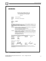
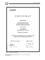
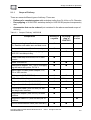
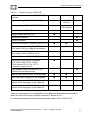
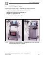
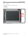
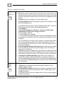
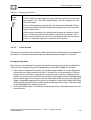
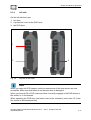
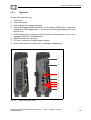

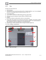
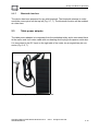

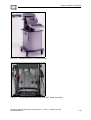
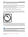
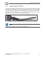
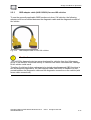
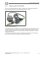
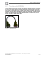
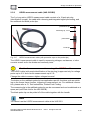
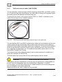
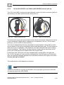
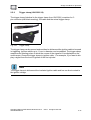
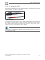
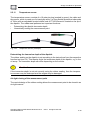
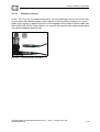
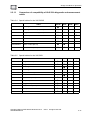
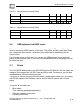

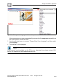
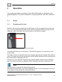
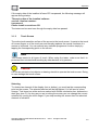
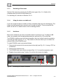
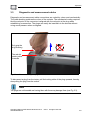
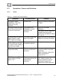
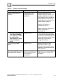
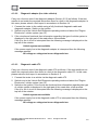
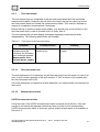
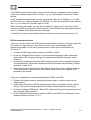

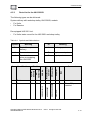
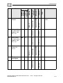
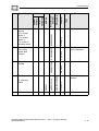
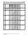
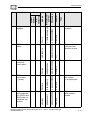
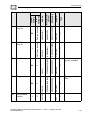
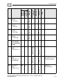
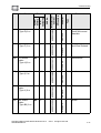
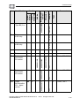
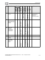
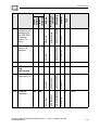
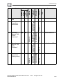

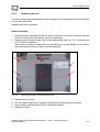
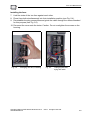
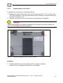
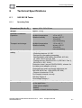
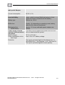
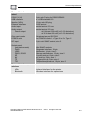
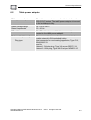
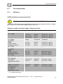
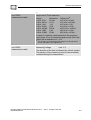
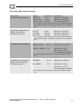

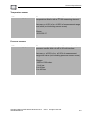
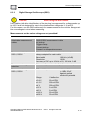
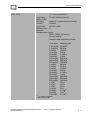
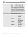
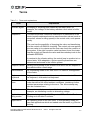
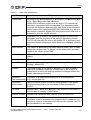
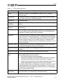
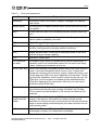
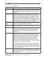
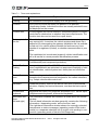
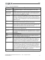
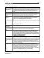
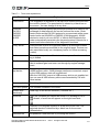
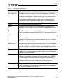
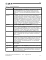
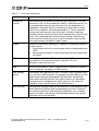


![CAST for PSI user`s manual [v07]](http://vs1.manualzilla.com/store/data/005903758_1-a858c2dfda3ffb28451a6ec48d1cfa02-150x150.png)