1
Cedex Bio HT
Operator's Manual
Version 1.2
Cedex Bio HT
Revision history
Manual
version
Software
version
Revision date
Changes
1.0
5.0
May 2012
First release
1.0
5.0
September 2012
Updated laser information
1.1
5.0
April 2013
Remote access, diluent handling, 2nd LAN
connector
1.2
5.0
September 2013
Hardware specifications, data handling via
USB
Publication notice
This publication is for users of the Cedex Bio HT analyzer.
Every effort has been made to ensure that all the information contained in this
publication is correct at the time of publishing. However, Roche reserves the right to
make any changes necessary without notice as part of ongoing product developments
and improvements.
Any customer modification to the instrument will render the warranty or service
agreement null and void.
Intended use
The Cedex Bio HT analyzer is a fully automated, computerized analyzer for
professional use. It is intended for determination of a wide range of analytes in various
aqueous solutions like cell culture and fermentation media.
For use in quality control/manufacturing process only.
Copyrights
Trademarks
© 2012-2013, Roche Diagnostics International Ltd. All rights reserved.
CEDEX, COBAS and ISE are trademarks of Roche.
All other product names and trademarks are the property of their respective owners.
Instrument approvals
The Cedex Bio HT analyzer meets the protection requirements laid down in:
o
Council Directive 2004/108/EC on the alignment of the legal provisions of the
Member States on electromagnetic compatibility (EMC).
o
Council Directive 2006/95/EC on the alignment of the legal provisions of the
Member States on electrical equipment for use within certain voltage limits.
Compliance is provided by means of the Declaration of Conformity.
Regulatory compliance is demonstrated by the following marks:
Complies with European Union (EU) Directives 2004/108/EC
and 2006/95/EC.
Issued by Underwriters Laboratories, Inc. (UL) for Canada
and the US.
-ii
Operator’s Manual · Version 1.2
Cedex Bio HT
Contact address
Roche Diagnostics GmbH
Sandhofer Strasse 116
68305 Mannheim
Germany
Made in Switzerland
Operator’s Manual · Version 1.2
-iii
Cedex Bio HT
-iv
Operator’s Manual · Version 1.2
Table of contents
Table of contents
Preface
Software virus warning
Safety labels on the system
Safety information for laser transmitters
Overview
1
2
3
4
System overview
Introduction
A first look at a Cedex Bio HT analyzer
Overview of user tasks
Basic principles
4
5
8
10
16
18
19
42
User interface
A first look at the user interface
Work areas
Working with the user interface
Tips and techniques
48
49
51
53
Online Help
Introduction
Starting and closing online Help
Help window
Finding information
Context Help
General Help
Message Help
Related topics
Glossary
56
57
58
62
65
67
68
70
71
Part B
Daily workflow
Introduction
5
Daily start-up
8
Daily routine (without sample barcode and without
host)
12
Daily routine (with sample barcode and without
host)
17
Daily routine (with sample barcode and with host)
22
End of day
27
User Manual · Version 2.7
6
Part A
System description
Panels and logos
Modules and main components
Functional systems
System states
Operation
5
v
ix
xviii
xx
xxi
7
8
9
Routine tasks
Starting up and logging on to the system
Logging off and shutting down the system
(Re)Starting and stopping a run
Handling test materials
Managing resources
Checking due service actions
Checking the Memo Pad
Printing reports
Purging and deleting information and items
Archiving system information
31
35
37
38
42
50
51
52
60
63
Status
About Status
Status work area overview
Missing & Blocked tab
Samples tab
Cassettes tab
Test Status tab
Analyzer tab
ISE tab
Displaying item details
Selected tasks
66
67
68
70
72
74
76
78
80
82
Orders
About orders
Orders at a glance
Orders work area
Worklist tab
Sample tab
Calibration tab
Quality Control tab
Creating an order
Working with Orders
84
85
87
89
91
93
94
95
102
Results
About results
Results work area overview
Validate tab
Sample tab
Calibration tab
Quality Control tab
Selecting specific orders
Displaying detailed information
Working with results
112
116
117
119
120
121
123
125
128
v
Troubleshooting
10 Calibration
About calibration
Calibrations at a glance
Reviewing the status of calibrators on board
Loading calibrators on board
Requesting calibrations
Postponing a calibration
Validating calibration results
Setting up calibrators
136
138
140
143
145
147
149
154
11 Quality controls
About controls
Controls at a glance
Reviewing the status of controls on board
Loading controls on board
Requesting controls
Reviewing and validating control results
Setting up controls
162
164
166
169
170
172
181
Flags
Part C
12 Result flags
About result flags
Flags and recommended actions
Service
5
6
Part D
13 Service action software
About service actions
Service work area overview
Due tab
All tab
Begin of Day tab
Performing a service action
Service notes
Counters and timers
14 Service actions
Deproteinize probes
Clean probes and splash guard
Clean internal water reservoir
Clean wash station
Clean external water reservoir and fluid waste
reservoir
Clean instrument
Clean the waste box fitting
Clean and lubricate the rotor
Prime the fluid system
Roche service
Backup database
Replace ventilation filter
Replace Abs. halogen lamp
Replace probe B (or C)
Replace plunger tip dosage pipette B (or C)
Replace dosage pipette B (or C)
Replace external water reservoir filter
Managing data
vi
5
6
7
8
9
11
13
15
23
24
27
30
33
36
42
43
46
47
48
49
51
54
57
61
64
66
Part E
15 Messages
About messages
New Messages tab
Message Log tab
Options tab
Working with messages
Putting the system into Standby
Stopping and restarting the system
4
6
7
8
9
11
12
16 Troubleshooting
Introduction
Start-up problems
Blocked orders, tests, calibrations, or controls
Results
Hardware
Software error messages
Data station accessories
External connectors
Checking and replacing fuses
Contacting Roche Service
17
18
19
26
29
34
35
37
40
44
ISE measurements
Part F
17 ISE module
Overview
How the ISE module works
Making ISE measurements
ISE solutions summary
Technical specifications
4
8
11
12
13
18 ISE service actions
About ISE service actions
Initialize ISE module
Electrode service
Activate electrodes
Prime ISE calibrators
Clean ISE tower automatically
Clean ISE tower manually
Replace ISE module tubing
Replace electrode
Condition ISE tubing
Replace ISE solutions on the ISE rack
Replace bottles on ISE module
Replace ISE tower
ISE Performance Check
16
17
18
19
20
21
22
25
27
31
32
34
36
37
19 ISE flags and troubleshooting
About ISE flags
Flags and user actions
Flag descriptions
General ISE troubleshooting
40
41
43
49
User Manual · Version 2.7
Configuration
20 Configuration
Configuration overview
About the Definitions group
Loading test application software
Archiving and reloading definitions
System group
Windows group
Appendix
21 Appendix
Technical specifications
Fluid system schematic
Keyboard shortcuts
Menu structure
Glossary and Index
Part G
4
6
17
19
20
22
Part H
4
11
13
14
Part I
Glossary
Index
3
9
Revisions
Part J
User Manual · Version 2.7
vii
viii
User Manual · Version 2.7
Cedex Bio HT
Preface
This manual refers specifically to the Cedex Bio HT analyzer and software version 5.0.
About the Cedex Bio HT analyzer
The Cedex Bio HT analyzer is an advanced integrated system for monitoring of
substrates and metabolites for process control of cell culturing and fermentation.
Testing of electrolytes, carbohydrates, amino acids, specific proteins and enzyme
activities is consolidated into one system with a convenient reagent cassette design.
Robust robotics, an intuitive user interface and random sample access serve for
optimized time management and streamlined workflows.
The ISE (Ion Selective Electrode) module allows the determination of sodium and
potassium in parallel with absorbance- and FP photometric measurements.
Reagent cassettes, calibrators, controls, and samples are identified by a barcode
scanner.
The high performance, flexibility, and versatility of the Cedex Bio HT analyzer make
this system suitable as a routine analyzer as well as a dedicated instrument for specific
tasks.
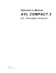
A
B
Roch
e
A Data station
B Instrument
Operator’s Manual · Version 1.2
-ix
Cedex Bio HT
How to use this manual
This manual is designed to help you perform all of the tasks that are required as part of
your work with the Cedex Bio HT analyzer.
If you are a new user, the manual will also help you to understand general hardware
principles, the user interface, the status of the instrument and its modules. You should
familiarize yourself with these areas before attempting to perform daily tasks.
You can also find information about how to use the Cedex Bio HT analyzer in the
Online Help.
Content
The manual is divided into the following parts:
o
Part A - Overview: Contains general information about the Cedex Bio HT
analyzer, about the basic concepts of using the instrument, the hardware, the
software, and the online Help.
o
Part B - Operation: Starts with a workflow description for some typical laboratory
setups, using step-by-step instructions. It then describes how to perform all the
day-to-day tasks necessary to create orders, monitor the status of the instrument,
view results, and deal with some simple problems that do not require detailed
analysis.
o
Part C - Flags: Describes the flags that are generated for unaccepted results and
gives recommended actions.
o
Part D - Service: Describes how to start and perform service actions that are
essential to maintain maximum productivity from this instrument.
o
Part E - Troubleshooting: Describes how to pinpoint potential problems and how
to solve them.
o
Part F - ISE measurements: Describes the principles of operation of the ISE
module and contains specialized sections on ISE flags and troubleshooting, and
ISE service actions.
o
Part G - Configuration: Describes some of the most common configuration tasks
for a fully operational system. Full details on all configuration procedures are
given in the online Help.
o
Appendix: Contains additional information including a technical specification of
the instrument.
o
Glossary and index: Provides reference and look-up material.
Conventions used in the Cedex Bio HT documentation
This section describes the conventions used in this manual, including symbols, userinterface conventions, and units.
Symbols
The following symbols are used:
Symbol
Used for
a
Step-by-step procedure
Cross reference
-x
m
Checklist
i
Notes
Operator’s Manual · Version 1.2
Cedex Bio HT
User interface
conventions
The following conventions are used throughout the user documentation:
User action
Meaning
Configuration / Tests / ID
1 Click Configuration in the navigation bar.
2 Double-click Tests in the Definitions
group.
3 Click the ID tab.
Choose File > Print Report > BOD Report
1 Click File in the menu bar.
2 Select Print Report from the menu.
3 Select BOD Report from the next menu.
Operator’s Manual · Version 1.2
Shift + F3
Press the Shift key and hold it down; press
and release the F3 function key; then release
the Shift key.
Click
Press the left button on the mouse or the
equivalent button on the system keyboard.
Click OK
Move the cursor to the OK button, and then
press the left mouse button.
Click Status
Click the Status button on the navigation bar.
Click Print
Click the Print button in the current window
or dialog box.
Right-click
Click the right mouse button (or equivalent
on the keyboard).
Press
Press a key on the keyboard.
Double-click
Click the left mouse button (or equivalent on
the keyboard) twice in rapid succession.
Open
Open the window or dialog box.
Close
Close the window or dialog box.
-xi
Cedex Bio HT
Units
SI units (Système International d’Unités) are used throughout the manual, where
appropriate. The following units are either non-SI or may be unfamiliar to some users:
Abbreviation
Unit
BTU
British thermal unit
cm
Centimeters
in
Inches
lb.
Pounds (weight)
M
Mega Ohm
psi
Pounds per square inch
VA
Volt-Amperes
VAC
Volts (alternating current)
S
Micro Siemens
Abbreviations and acronyms
The following abbreviations and acronyms are used throughout the documentation.
-xii
Abbreviation
Meaning
Usage
abs.
absorbance
abs. measurement
BOD
Begin of Day
BOD service action
CAL
calibrator
(legend on graphic)
DIL
diluent
(legend on graphic)
FP
Fluorescence Polarization
FP photometer
ID
Identification (number)
Order ID, Sample ID
in.
internal
in. water reservoir
ISE
Ion Selective Electrode
ISE module
LCD
Liquid crystal device
LCD monitor
LED
Light-emitting diode
LED status indicator
No.
number
Lot No.
STAT
immediate order
Priority samples, tests and results
TAS
Test Application Software
Roche default test, calibration,
control, and diluent definitions
Operator’s Manual · Version 1.2
Cedex Bio HT
Safety classifications
The safety precautions and important user notes are classified according to the
following description. Before you attempt to use the Cedex Bio HT analyzer, you must
be fully familiar with the following symbols and their meanings:
Indicates a direct danger that, if not avoided, may result in death or serious injury.
Indicates a possibly hazardous situation that, if not avoided, may result in death or serious injury.
Indicates a possibly hazardous situation that, if not avoided, may result in slight or minor injury
or may result in damage to equipment.
Safety information
Before operating the Cedex Bio HT analyzer, it is essential that you both read and
understand the safety information listed below.
Read all Roche safety notices carefully and make sure you understand them.
Electrical safety
Danger of electric shock when touching power supply components. Never attempt to access
any parts of the instrument other than those specifically described in the user documentation. In
particular, never open or manipulate any components on the rear of the instrument.
Electrical safety
Before removing main cover disconnect mains plug from socket. Hazardous voltage is present
on ISE power supply even if main switch is off. Danger of electric shock when touching power
supply components.
Biological safety
Samples analyzed with this instrument may contain potentially infectious material. Samples
derived from humans, animals, tissue culture, or in vitro cultures should be handled and
processed with appropriate safety precautions. Such samples may contain bacterial, fungal or
viral agents. Spills should be immediately disinfected with an approved disinfectant solution to
avoid contamination of laboratory personnel and equipment.
Operator’s Manual · Version 1.2
-xiii
Cedex Bio HT
Loss of sight due to staring into laser beam
Barcode scanner contains a class 2 laser diode.
Do not stare into the laser transmitter beam as your eyesight may be severely damaged.
For position of the laser transmitters, see "Safety information for laser transmitters" on page xxi.
Danger of explosion
Danger of explosion through sparks. Keep all potentially inflammable or explosive material (for
example anesthetic gas) away from the instrument.
Fire risk
Spraying liquid on the power supply parts can cause a short circuit and result in a fire. Keep the
cover closed while the instrument is connected to the main power supply and do not use sprays
in the vicinity of the Cedex Bio HT analyzer.
During fire-fighting operations disconnect the Cedex Bio HT analyzer from the main power
supply.
Instrument in use
Danger of injury to hands by moving parts. Keep the instrument cover closed while initialization
or measuring is in progress.
Malfunction of instrument and incorrect results due to interfering
electromagnetic fields
Devices that emit electromagnetic waves may cause the instrument to malfunction. Do not use
this device in close proximity to sources of strong electromagnetic radiation (e.g. unshielded
intentional RF sources), as these can interfere with the proper operation.
Sample
Danger of infectious sample material which can cause severe illness. Avoid direct contact with
sample material. Clean contaminated surfaces immediately and dispose of waste according to
regulations.
Sample
Samples containing solids can produce incorrect results or block probes. For good sample
quality, follow the instructions given by the primary tube manufacturers.
Light source
Danger of eye damage from the bright light of the absorbance photometer lamp. Always wear
dark safety glasses when looking at the light.
Waste
Danger of infectious waste material. This can cause severe illness. Avoid direct contact with
waste.
-xiv
Operator’s Manual · Version 1.2
Cedex Bio HT
Carry-over
Traces of analytes may be carried over from one sample to the next. Take adequate measures to
safeguard correct testing of high-sensitive methods (e.g. heterogeneous immuno-assays).
Cassette interchange
Do not interchange cassettes among different Cedex Bio HT systems and instruments. Each
cassette rack with its cassettes may be used on one individual Cedex Bio HT instrument only.
Each cassette has its own individual cassette number, which the instrument uses to identify it.
Using a cassette already used on a different Cedex Bio HT instrument may lead to incorrect
results.
If more than one Cedex Bio HT instrument is used in the same lab, be sure to dedicate each
cassette rack with its cassettes to one single, individual instrument (e.g. by color coding).
Sample
Samples containing solids can produce false results and block probes. Ensure that samples are
free from insoluble particles.
Reagents
Danger of cauterization and skin poisoning through contact with reagents. Pay attention to the
warnings on the cassettes.
Foam
Danger of false results. Avoid the formation of foam when handling reagents, samples,
calibrators, and controls.
Waste material
Disposal of all waste material should be in accordance with local guidelines.
Correct use
Use the Cedex Bio HT system only to measure liquid samples with the provided reagents.
User qualification
Danger due to incorrect operation.
The Cedex Bio HT analyzer should be used by qualified users only.
Operator’s Manual · Version 1.2
-xv
Cedex Bio HT
Cleaning and maintenance
Incorrect cleaning and maintenance can cause damage to personnel and equipment. Perform
cleaning and maintenance according to the procedures described in this publication.
Environmental conditions
Incorrect location can cause incorrect results and damage equipment components. Follow the
installation instructions carefully. Relocating the Cedex Bio HT analyzer should be carried out
by Roche Service only.
Cleaner
Incorrect cleaning materials can damage the Cedex Bio HT analyzer. Organic solutions damage
cuvettes, tubing, and other plastic materials. Use only 70% ethanol solution to clean the
equipment.
Disposal recommendations
All electrical and electronic products should be disposed of separately from the municipal waste
system. Proper disposal of your old appliance prevents potential negative consequences for the
environment and human health.
Disposal of Control Unit Components
Components of your Control Unit such as the computer, monitor, keyboard, etc. which are
marked with the crossed-out wheeled bin symbol are covered by the European Directive on
Waste Electrical and Electronic Equipment (WEEE).
These items must be disposed of via designated collection facilities appointed by government or
local authorities.
For more information about disposal of your old product, please contact your city office, waste
disposal service or your local Roche Support personnel.
Disposal of the Instrument
The instrument must be treated as biologically contaminated-hazardous waste.
Decontamination (i.e., a combination of processes, including cleaning, disinfection and/or
sterilization) is required before reuse, recycling or disposal.
Dispose of the instrument according to local and/or labor regulations. For more information
contact your local Roche Support personnel.
Disposal recommendations
All electrical and electronic products should be disposed of separately from the municipal waste
system. Proper disposal of your old appliance prevents potential negative consequences for the
environment and human health.
-xvi
Operator’s Manual · Version 1.2
Cedex Bio HT
Disposal of Control Unit Components
Components of your Control Unit such as the computer, monitor, keyboard, etc. which are
marked with the crossed-out wheeled bin symbol are covered by the European Directive on
Waste Electrical and Electronic Equipment (WEEE).
These items must be disposed of via designated collection facilities appointed by government or
local authorities.
For more information about disposal of your old product, please contact your city office, waste
disposal service or your local Roche Support personnel.
Disposal of the Instrument
The instrument must be treated as biologically contaminated-hazardous waste.
Decontamination (i.e., a combination of processes, including cleaning, disinfection and/or
sterilization) is required before reuse, recycling or disposal.
Dispose of the instrument according to local and/or labor regulations. For more information
contact your local Roche Support personnel.
The electromagnetic environment should be evaluated prior to operation of the device.
This equipment has been tested and found to comply with the limits for Class B digital
device, pursuant to part 15 of the FCC Rules. These limits are designed to provide
reasonable protection against harmful interferences when the equipment is operated
in a residential area. However, this equipment generates, uses, and can radiate radio
frequency energy and, if not installed and used in accordance with the present user
manual, may cause harmful interference to radio communications.
Uninterruptible power supply (UPS)
Depending upon the quality of electrical grounding of the local electrical power
supply, an uninterruptible power supply (UPS) may be required. A UPS is not
provided with the Cedex Bio HT analyzer. The UPS should provide at least the
maximum power listed in the Technical specifications provided in this manual.
Operator’s Manual · Version 1.2
-xvii
Cedex Bio HT
Software virus warning
Portable storage media can be infected with and transmit computer malware (for example virus,
Trojan horse).
The Cedex Bio HT is not protected against malware.
The customers are responsible for IT security of their IT infrastructure and for preventing the
spread of malware from system to system.
Recommendations
o
Allow connection to authorized external devices only.
o
Ensure that all external devices are protected by appropriate security software.
o
Ensure that access to all external devices is protected by appropriate security
equipment.
o
Do not copy or install any software on the Cedex Bio HT unless it is part of the
system software or you are instructed to do so by Roche Service.
o
Do not move or delete any software on control units unless you are instructed to
do so by Roche Service.
o
If additional software is required, contact Roche Service to ensure validation of the
software in question.
o
Do not use the USB ports to connect other storage devices unless instructed to do
so by the official user documentation or Roche Service.
o
Exercise utmost care when using external storage devices such as USB flash drives,
CDs, or DVDs. Do not use them on public or home computers while connecting
to the Cedex Bio HT.
o
Keep all external storage devices in a secure place and ensure that they can be
accessed by authorized persons only.
o
Use the remote services modem only for contacting Roche Service or when
instructed to do so by Roche Service.
Failure to observe these recommendations may result in wrong data, lost data, or the
non-availability of the system.
If this product is connected to a local area network, this network must be protected against
unauthorized access. In particular, it must not be linked directly to any other network or the
Internet. Customers are responsible for the security of their local area network, especially in
protecting it against malicious software and attacks. This protection might include measures,
such as a firewall, to separate the device from uncontrolled networks as well as measures that
ensure that the connected network is free of malicious code.
For further information, contact Roche Service.
-xviii
Operator’s Manual · Version 1.2
Cedex Bio HT
The 2nd LAN connector must only be used for Roche remote service connectivity. If a remote
service connection is established over an insecure network via an AXEDA client, the device
must be installed behind either a Roche “connect 2” device or a cobas link gateway. The use of
an AXEDA client is the only approved and supported remote service solution. Other nonintended usage of the LAN connectors could lead to unauthorized database access resulting in
possible disclosure or modification of sensitive data.
Operator’s Manual · Version 1.2
-xix
Cedex Bio HT
Safety labels on the system
Warning labels have been placed on the analyzer to draw your attention to areas of
potential hazard. The labels for the laser transmitter are listed below according to their
location on the analyzer.
The safety labels on the instrument comply with the following standards: ANSI Z535,
IEC 61010-1, IEC 60417-DB-3M, or ISO 7000.
If the labels are damaged, they must be replaced by Roche Service personnel. For
replacement labels contact your local Roche representative.
Safety label on analyzer
Location and meaning
Laser transmitter warning
Situated inside of the rack access panel
to designate the presence of a laser
transmitter. Do not stare into the laser
transmitter.
Laser transmitter warning
Situated outside of the rack access panel
to designate the presence of a laser
transmitter. Do not stare into the laser
transmitter.
For details, see "Safety information for laser transmitters" on page xxi.
-xx
Operator’s Manual · Version 1.2
Cedex Bio HT
Safety information for laser transmitters
The Cedex Bio HT analyzer is a class 2 laser product. It contains one laser transmitter:
Class 2 laser transmitter inside the barcode scanner on the right side of the analyzer
behind the rack access panel to scan rack, cassette, and sample barcodes.
Loss of sight due to staring into laser beam
Do not stare into the laser transmitter beam as your eyesight may be severely damaged.
Classification
The mentioned class refers to the standard IEC 60825-1:
o
Class 2:
Visible lasers. Eye-safe for accidental viewing. However, it may not be safe for a
person who deliberately stares into the laser beam for longer than 0.25 s, by
overcoming their natural aversion response to the very bright light.
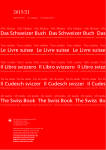
The following figure shows the position of the laser transmitter and the directions of
its apertures on the Cedex Bio HT analyzer:
Sup
ply
Fus 36V
e 5AT
Sup
ply
Fus 100
e 3.2 V
AT
5V
+15V
-15V
FP
Lam
Fus p Sup
e 6.3 ply
AT AB
S
24V Transfer Z
Fuse 3.2AT
24V Resource Reagent
Fuse 3.2 AT
24V Resource Sample
Fuse 3.2 AT
24V Transfer XY/Cuvette
Fuse 3.2 AT
24V Measure
Fuse 3.2 AT
24V Analyzer/Fluid
Fuse 3.2 AT
LED
Fus Sup
e 2ATply
LPT 1
DS
HUB
HUB
n
Cautio
user manual
on
ction
iond instructi
Attent d©instru
Refer to
R
RD NE
ZA AI
HA
NT
BIO CO
TE
AS
W
z le manuel
Consulte
A
I
Figure 0-1
Location of laser transmitter
A Laser transmitter behind rack access panel
Operator’s Manual · Version 1.2
-xxi
Cedex Bio HT
Laser Location
A
-xxii
Usage
Behind rack access panel (right side) Barcode scanner
Wavelength
Pulse duration
Output radiation
650 nm
132 s
1.1 mW
Operator’s Manual · Version 1.2
Overview
A
Part A gives you an overview of the whole system. It includes a
general introduction plus a description of the hardware and its
functional systems, the user interface, and the Help system.
1 System overview
Cedex Bio HT
System overview
A quick look at the Cedex Bio HT analyzer
This chapter provides an overview of the Cedex Bio HT analyzer and its main features.
It also provides an introduction to some of the key ideas that are developed later on in
the manual.
In this chapter
Chapter
1
Introduction ........................................................................................................................A-4
What the system does ..................................................................................................A-4
A first look at a Cedex Bio HT analyzer ...........................................................................A-5
Instrument.....................................................................................................................A-5
Data station ...................................................................................................................A-6
Overview of user tasks........................................................................................................A-8
Cleaning the instrument externally ...........................................................................A-9
Basic principles..................................................................................................................A-10
Sample handling .........................................................................................................A-10
Cassettes and reagents ...............................................................................................A-11
Calibrations and quality controls.............................................................................A-11
Result handling...........................................................................................................A-12
System status...............................................................................................................A-12
Maintenance, service, and troubleshooting............................................................A-12
Waste disposal ............................................................................................................A-12
Automatic start-up.....................................................................................................A-13
A
A
Operator’s Manual · Version 1.2
A-3
1 System overview
Cedex Bio HT
Introduction
Introduction
The Cedex Bio HT system is a random and continuous selective analyzer designed to
operate from a table top. There are three separate measurement systems supporting
four different measurement principles:
Measurement system
Measurement principle
FP photometer
Fluorescence polarimetry
Absorbance photometer
Absorbance photometry
Turbidimetry
ISE (Ion-Selective Electrode) module Ion selective potentiometry
Samples are automatically transferred from a sample tube or cup to the module where
the measurements are made. All optical measurements use the same transparent
plastic containers, called cuvettes.
The graphical user interface provides quick and easy access to sample, control, and
calibration data, while continuously monitoring all system functions. Color-coded
icons alert you to changes in the system status. Connection to a host system allows for
automatic transfer of results to and from the Cedex Bio HT analyzer.
What the system does
The system consists of the instrument and the data station.
The instrument runs tests on samples, calibrators, and controls, and produces the
results. The data station analyses and further processes the results.
Here are just some of the actions the system performs automatically:
A-4
o
Delivers the correct volumes of samples, reagents and other solutions to the
measuring modules.
o
Reads the barcodes on reagent cassettes, samples (if barcoded), and other
solutions.
o
Performs washing and cleaning cycles to minimize carry-over between tests.
o
Takes the physical measurements on which the results are based.
o
Calculates and ensures the integrity of the result, generating flags for suspect ones.
o
Keeps track of all samples, tests, and orders on the instrument.
o
Collates results into reports for printing or transmission to another computer
system.
o
Stores the results on each sample and test in a database.
Operator’s Manual · Version 1.2
1 System overview
Cedex Bio HT
A first look at a Cedex Bio HT analyzer
A first look at a Cedex Bio HT analyzer
Instrument
The instrument carries out all test orders automatically and is equipped with
measuring modules for absorbance photometry (Abs.), fluorescence polarization (FP)
photometry, and for ISE measurements.
Colored LEDs (light-emitting diodes) on the rack status indicator panel on the front
of the instrument tell you the current status of on-board cassette and sample racks.
C
A
LPT 1
B
Ro
che
DS
HUB
HUB
I
Figure 0-2
D
E
A first look at the Cedex Bio HT instrument
A Main cover
B Status indicator panel
C External waste, water, and power connections (not shown)
D Data connectors (for connection to the data station and the LAN)
E Main switch
The system is designed to run continuously, 24 hours a day, if necessary. However, an
On/Off switch (main switch) is provided if you need to switch off the power to the
system in an emergency or for troubleshooting.
“Switching on the system” on page B-31
“Shutting down the system” on page B-35
External waste, water and power connections are made at the rear of the instrument.
The instrument may be connected to the laboratory waste and water system or you
can use external waste and water reservoirs.
Data station
The data station comprises the elements shown below:
Operator’s Manual · Version 1.2
A-5
1 System overview
Cedex Bio HT
A first look at a Cedex Bio HT analyzer
A
B
C
E
F
Figure 0-3
D
A first look at the Cedex Bio HT data station
A Monitor
B Barcode pen (optional) or handheld barcode scanner (optional)
C Mouse
D Keyboard
E Printer (optional)
F Computer
User interface
You can control the user interface with the mouse and keyboard. The user interface is
structured as a series of work areas; the main ones are Status, Orders, Results, and
Service. Each work area contains two or more tabs. By clicking a tab, you can move
around the work area.
You can display any test results on the monitor or print reports containing
information on samples, orders, and results. Connection to a local printer is optional.
You can manually enter orders for tests on samples in the Orders work area.
Alternatively, the system receives orders electronically from a host system, if your
Cedex Bio HT is connected to such a system.
System messages are displayed in the Messages work area, and you can communicate
with other users by using the Memo Pad.
Chapter 3, “User interface”
Computer
A-6
The computer performs tasks in connection with order processing, data management,
and user interface management. It makes it possible to simultaneously manage data
and enter new orders. Figure 0-4 shows the appearance of the computer for
Cedex Bio HT systems.
Operator’s Manual · Version 1.2
1 System overview
Cedex Bio HT
A first look at a Cedex Bio HT analyzer
A
B
Figure 0-4
A
C
B
Computer for Cedex Bio HT systems.
Newer model (left) and older model (right).
A DVD drive.
Used for upgrades and data mirroring.
B USB Ports.
Information can be saved on USB Memory Stick.
C Diskette drive.
In older Cedex Bio HT systems, information can be saved on 3.5-inch diskettes.
Barcode pen or
handheld barcode scanner
You use the barcode pen or handheld barcode scanner to read calibrator and control
lot data located on the barcodes of the package inserts.
Figure 0-5
Using the barcode pen (left) or handheld barcode scanner (right)
“Setting up calibrators” on page B-154
Operator’s Manual · Version 1.2
A-7
1 System overview
Cedex Bio HT
Overview of user tasks
Overview of user tasks
Figure 0-6 shows some of the main access points for tasks you perform regularly.
3
4
5
3
4
5
FP
Sup
Fus ply 100
e 3.2A V
T
F
5V
+15V
-15V
Lam
Fus p Sup
e 6.3Aply
T ABS
24V Transfer Z
Fuse 3.2AT
24V Resource Reagent
Fuse 3.2 AT
24V Resource Sample
Fuse 3.2 AT
24V Transfer XY/Cuvette
Fuse 3.2 AT
24V Measure
Fuse 3.2 AT
24V Analyzer/Fluid
Fuse 3.2 AT
LED
Fus Sup
e 2ATply
Sup
Fus ply 36V
e 5AT
V6
1
V6
3
V6
2
V6
0
V5
1
R
TO
RA
V5
3
LIB
CA
T
REC
INDI
V5
4
R
TO
RA
LIB
CT
DIRE
CA
LPT 1
e
enc
fer lyte
Re ctro
Ele
07
6306
3Art.
ne
DS
ct/uri
indire
Roche
rator
ISE
C
Calib
15-25
ml
250
use
vitro
in
ml
de
ence
rféré
for
redü
fr
Roche
La
s
pour
Manufactu
Hergestellt
Hoffmann- Inc.
Fabrique
F.
Diagnostic
of
Systems,
Roche Basel
1
a division
202
CH-4070
Diagnostic
g Township
08876-377
NJ
Roche Highway
AG
US lle,
Branchbur
RocheWyhlen
1080
Sommervi La
Grenzach-Seine
HoffmannD-79630 Roche
Neuilly-sur
Produits
F-92521
Ltd
10834
Lot/Ch.-B. P
mol/L
Exp./Verw. bis1999.10
Electrolyteuse
um
diagnostic
vitro
in diagnostic
Forvitroin vitro
In
Usage
KCI+
um
Na+
ü
Inc.
Roche
Systems,
Basel
a division
Hoffmann1
F.
202
CH-4070
Diagnostic
g Township
08876-377
NJ
Roche Hihgway
AG
US lle,
Branchbur
RocheWyhlen
1080
Sommervi La
Grenzach-Seine
HoffmannD-79630 Roche
Neuilly-sur
Produits
F-92521
2934
Lot/Ch.-B. P
s
pour
Ltd
Manufactu
Fabrique
Diagnostic
Inc.
of La Roche
Roche
Systems,
Basel
a division
Hoffmann1
F.
202
CH-4070
Diagnostic
g Township
08876-377
NJ
Roche Hihgway
AG
US lle,
Branchbur
RocheWyhlen
1080
Sommervi La
Grenzach-Seine
HoffmannD-79630 Roche
Neuilly-sur
Produits
F-92521
ISE
t
nzelektroly
ISE-Refere
3.5
Exp./Verw. bis1999.10
ISE
250
ü
diagnostic
diagnostic
vitro
In
s
pour
Ltd
Manufactu
Fabrique
Diagnostic
of La Roche
um
diagnostic
diagnostic
vitro
In
vitro
HUB
in
vitro
nmol/L K+
25
nmol/L CIfr
0.83 nmol/L Li+
19.2 nmol/L Hergestellt
for/
0.05 red
C
15-25
use
vitro
HUB
in
Na+
Usage
nmol/L K+
150 nmol/L CI5
fr
nmol/L Li+
115 nmol/L Hergestellt
0.3 red for/
C
15-25
P 1531
in
Usage
rator
Calib
ml
250
For
ence
Refer
Lot/Ch.-B.
For
t
direc
Roche
ISE
07
3808
5Art.
42371
US#
rolyte
Elect
Roche
Exp./Verw. bis1999.07
07
6305
5Art.
6306/A
6306/A
6306/A
Prüfkas
FPTE sete
07 GI
Lot5534
E0836
5V
Tests
130
124
Serienu
00279 mmer
4
Prüfkas
FPTE
sete
07 GI
Lot5534
E0836
5V
Tests
1
130
Serienu
00279 mmer
4
Prüfkas
FPTE sete
07 GI
Lot5534
E0836
5V
Tests
2
130
manual
Caution
to user
n
nd
©instructio
Attentio
le manuel
Serienu
00279 mmer
Refer
RD ER
ZA
AIN
HA NT
CO
E
ST
WA
3
Serienu
00279 mmer
BIO
3
Prüfkas
FPTE sete
07 GI
Lot5534
E0836
130
5V
Tests
A
Consultez
005
4
1
2
TE
ET
SS
CA
4
24
S
BA
CO
3
4
5
6
7
8
9
2
10
3
11
Rackcode 014
1
B
12
4
13
5
LE
MP
SA
14
5
6
S
BA
CO
15
7
8
C
ER
AIN
NT
RD
CO
ZA
E
HA
ST
WA
BIO
ISE
14
S
BA
CO
I
D
E
Figure 0-6
Main access points to the instrument
A Cassette rack with reagent cassettes
B Sample rack with samples (or calibrators, controls, and diluents)
C ISE rack with ISE solutions, special cleaners, and diluents
D Cuvette reservoir for new cuvettes
E Disposable cuvette waste box (autoclavable) for used cuvettes
F Connections to water and waste are made on the rear panel (not shown)
G Data connectors
Here are some important user tasks:
A-8
o
Perform service actions.
o
Prepare resources, for example, mix cassettes.
o
Replace consumables such as cleaners, cuvettes and dispose of used ones.
o
Print reports, for example, the Loadlist.
o
Load racks containing samples, reagents (cassettes), calibrators, controls, cleaners
and diluents. Remove processed racks.
o
Create orders and request calibrations and controls.
o
Monitor the status of the instrument: check resources and Missing & Blocked in
the Status work area.
o
Validate results.
o
Troubleshoot problems.
Operator’s Manual · Version 1.2
G
1 System overview
Cedex Bio HT
Overview of user tasks
o
Remove waste, for example, used cuvettes or waste liquid.
o
Delete results and orders.
Cleaning the instrument externally
You can clean the instrument externally with a cloth and a soap solution with mild
disinfectant, or a solution of 70% ethanol.
Incorrect cleaning materials can damage the Cedex Bio HT analyzer.
Service actions
Operator’s Manual · Version 1.2
o
Do not clean the instrument while it is switched on.
o
Do not use organic cleaning solvents (for example, petroleum, benzene, petrol or
other solvents) because they can damage cuvettes, tubing, and other plastic
materials.
o
Do not use an alcohol solution with a concentration of greater than 70% alcohol,
because this may damage transparent viewing windows.
o
Do not use sodium hypochlorite solution because it causes corrosion on metal
parts.
You must perform all internal cleaning tasks according to the instructions given in the
user documentation and provided online as part of the software assisted service
actions. You review and perform service actions in the Service work area. The system
prompts you when service actions are due.
A-9
1 System overview
Cedex Bio HT
Basic principles
Basic principles
This section provides a quick introduction to some of the key features of the
instrument and how you use it.
Sample handling
Samples can be placed in 5, 5.5, 7, 7.5 or 10 mL primary tubes. Cups and Cup on Tube
can be used for smaller volumes of rare samples.
Figure 0-7
Sample rack
Sample racks allow continuous access to samples as tests are completed and new
samples arrive. Samples can be barcoded to allow the positive identification of samples
by the system. You can add or remove the racks as necessary. When you insert a rack,
the sample barcodes are read automatically.
The samples on the left most rack (rack in slot with lowest position letter) are
measured first, followed by those on the rack next to it on the right.
STATs are automatically given priority to speed up the delivery of results, while the
routine workflow remains uninterrupted.
Cassettes and reagents
All tests use the same reagent cassette design. A large number of reagent cassettes
specifically tailored to the Cedex Bio HT systems are available in an easy-to-use, easyto-store design.
Figure 0-8
A-10
Cassette rack
Operator’s Manual · Version 1.2
1 System overview
Cedex Bio HT
Basic principles
You put cassettes onto a cassette rack, which you can load or remove while the system
is running. Cassette labels are barcoded for fast, accurate, and secure entry of reagent
data, such as the number of tests, lot number, and expiration date. .
o
When handling multiple cassette racks, wait at least three seconds before you manually
handle the next rack.
o
When inserting a cassette rack, try to tilt the rack slightly clockwise (5-10°), so that the
barcode is not read at an exactly 90° angle. This can help in case of barcode reading
problems due to unwanted surface reflection from a glossy barcode label material.
Do not interchange cassettes among different Cedex Bio HT instruments. Each cassette rack
with its cassettes may be used on one individual Cedex Bio HT instrument only. Each cassette
has its own individual cassette number, which the instrument uses to identify it. Using a cassette
already used on a different Cedex Bio HT instrument may lead to incorrect results.
If more than one Cedex Bio HT instrument is used in the same lab, be sure to dedicate each
cassette rack with its cassettes to one single, individual instrument (e.g. by color coding).
The list of on-board tests is continuously monitored; you are automatically notified
when the supply is low. Color-coded cassette graphics tell you at a glance when you
need to load new cassettes. Once you load a new cassette, the system automatically
uses the new cassette as soon as the current one is used up. The system tracks the
reagents available on board and forecasts if additional cassettes are required based on
your workflow statistics. Test data is stored even after a cassette has been removed.
Calibrations and quality controls
Calibrators and quality controls use the same types of tubes and racks as samples. A
refrigerated rack position improves the stability of on-board calibrators and controls.
The system performs calibrations and controls automatically according to the
specification in the test definition. Alternatively, you can request a calibration or
control manually. The system tells you when calibrations or controls are required and
when there is not enough calibrator or control material on board to complete the
request.
You can use precision, accuracy, or limit controls. You can use up to six controls per
test, and you can exclude suspect controls from the statistics.
Result handling
The system automatically generates flags for all results that do not meet the required
specifications. You can apply rules to ensure reliable results. On-screen LeveyJennings plots allow a quick review of results.
Accepting results
Operator’s Manual · Version 1.2
An auto-accept feature means that you can choose whether appropriate results are
accepted automatically, for example, if they have no test or quality control flags and
are within range. You can display all non-accepted results (for samples, calibrators, or
A-11
1 System overview
Cedex Bio HT
Basic principles
controls) in the user interface. For each non-accepted result, you can choose to accept
the result or rerun the measurement, for example with dilution.
If you accept flagged calibration or quality control results, all results in tests that use those
calibrations or controls will be suspect.
System status
The system continually monitors its own status and informs you when resources are
low. You can then take the required action to keep the system running. For example,
when the supply of cuvettes is low, the icon and background color of the Status button
on the navigation bar change.
The Missing & Blocked tab in the Status work area, and the Worklist tab in the Orders
work area tell you which tests are blocked and what you have to do to remove the
block. For example, if a test cannot run because a calibrator is not on board and a
calibration is overdue, the system tells you. Once you have loaded the calibrator, the
system can perform the calibration and then the test.
Maintenance, service, and troubleshooting
Essential maintenance activities (referred to as service actions) are automatically
tracked by the system. The system prompts you when you need to perform a service
action. Online wizards guide you through the service actions, and additional step-bystep information is available in the online Help and later in this manual. The system
uses workload statistics to establish the interval between service actions rather than
using a fixed number of days.
For each service action performed, the system automatically logs the user, date, time,
and comments in accordance with standard good laboratory practice.
Context-sensitive online Help provides troubleshooting information on hardware and
software. If you cannot solve a problem yourself, you can contact Roche Service, who
can (with your permission) dial into your system via the “connect 2” box or a cobas
link gateway and control it remotely. You can then work together to resolve errors
quickly and efficiently without waiting for an on-site service visit.
Waste disposal
The liquid waste from rinsing and cleaning operations is automatically removed from
the instrument. Waste system water is transferred either to an external container or to
the laboratory waste system.
Sample and reagent waste is removed with the cuvette. Used cuvettes are
automatically dropped into the cuvette waste box. You have to remove the waste box
and dispose of it, according to your local procedures for dealing with hazardous waste.
ISE waste is transferred directly to the cuvette waste box.
Automatic start-up
At the beginning of each day, the system goes through a series of automatic service
actions. Typically, these actions are performed before the work day begins, so that the
instrument is ready to use when you start work.
A-12
Operator’s Manual · Version 1.2
Cedex Bio HT
1 System overview
Basic principles
Begin of Day
The time allocated for these service actions is called Begin of Day (BOD), and the
service actions are called the BOD service actions.
While these service actions are being performed, the system cannot run any tests.
However, you can terminate BOD, if you need to run urgent (STAT) orders.
Operator’s Manual · Version 1.2
A-13
1 System overview
Cedex Bio HT
Basic principles
A-14
Operator’s Manual · Version 1.2
2 System description
Cedex Bio HT
System description
Finding your way around the system and its hardware
A
This chapter gives an overview of the hardware and provides more detailed
information about the main functional systems. Some of the features described are
available only if your system is configured to support them.
In this chapter
Chapter
2
Panels and logos................................................................................................................A-16
External connectors ...................................................................................................A-17
Modules and main components .....................................................................................A-18
Functional systems ...........................................................................................................A-19
Fluid system ................................................................................................................A-20
Cuvette transport system ..........................................................................................A-24
Rack system.................................................................................................................A-27
Robotic transfer system .............................................................................................A-35
Analyzer module ........................................................................................................A-37
Computer systems......................................................................................................A-40
System states ......................................................................................................................A-41
Transitions between states ........................................................................................A-42
Operator’s Manual · Version 1.2
A-15
2 System description
Cedex Bio HT
Panels and logos
Panels and logos
You can open access panels when you need to work on the internal parts of the
instrument. Logos on the panels help you to find your way around.
A
LPT 1
Ro
ch
e
DS
B
HUB
HUB
E
C
D
I
Figure 0-9
Access panels
A Main front cover: gives access to the PCB fuses, pipette module and cleaner reservoir,
transfer arm and probes, initialization posts, and wash station.
Always lift the cover as far as it will go when opening it.
B ISE access panel: open downwards to pull out the ISE module.
See “Parts of the ISE module” on page F-5.
C Rack access panel: open downwards to load or remove racks.
See “Loading samples” on page B-38.
D Cuvette waste panel: open downwards to remove and replace the cuvette waste box.
See “Replacing the cuvette waste box” on page B-48.
E Cuvette reservoir access panel: lift up to remove the cuvette reservoir when you need to
add more cuvettes. See “Refilling the cuvette reservoir” on page B-44.
F Service access panel: lift up to remove for example a stuck cuvette. When opening the
panel make sure to secure the panel with the Locking Device Auxiliary Front Panel. When
closing the panel again, first release the bracket and then close the panel slowly.
A-16
Operator’s Manual · Version 1.2
2 System description
Cedex Bio HT
Panels and logos
Do not attempt to remove items from any of these locations without first referring to the
appropriate section in this manual or to the appropriate topic in the online Help.
Always close any access panels you have opened when you have finished working on
that part of the instrument.
The side panels are detachable. You can remove them by pulling them as shown
below. When you reinstall the side panels, make sure that they click securely into
place.
C
A
LPT 1
Ro
che
DS
HUB
HUB
B
I
Figure 0-10
Side access panels
A Left side panel
Provides access to the main fuses, frequency selection switches, internal water reservoir, and drip tray.
B Right side panel
Provides access to analyzer rotor, absorbance photometer, FP photometer, and cuvette transport
system.
C Rear panel (not shown)
Not detachable without a tool set. Does not provide access to any user-serviceable parts.
External connectors
The external connectors are located at the back (water, waste, and power) and on the
right side (data connectors) of the instrument.
“External connectors” on page E-37
Operator’s Manual · Version 1.2
A-17
2 System description
Cedex Bio HT
Modules and main components
Modules and main components
Figure 0-11 shows how the modules and components are arranged inside the
instrument.
A
J
3
4
5
3
4
5
La
mp
Fu Su
se
6.3 pply
A
T AB
S
Su
pp
Fu ly 36
se
5AT V
Su
pp
Fu ly 10
se
3.2 0V
A
T
K
5V
+15V
-15V
B
24V Transfer Z
Fuse 3.2A
T
24V Resource Reagent
Fuse 3.2 AT
24V Resource Sample
Fuse 3.2 AT
24V Transfer XY/Cuvette
Fuse 3.2 AT
24V Measure
Fuse 3.2 AT
24V Analyzer/Fluid
Fuse 3.2 AT
LE
D
Fu Su
se pp
2AT ly FP
L
V61
M
V63
V62
V60
R
TO
RA
V51
V53
LIB
CA
CT
IRE
IND
V54
R
TO
RA
LIB
CA
ECT
DIR
LPT 1
C
e
nc
fere lyte
Re tro
ec
El
07
6306
3Art.
N
e
/urin
DS
rect
e
Roch
indi
or
C
brat
ISE
Cali
15-25
ml
07
6305
5Art.
250
For
in
tic
vitro
use
ticum
diagnos diagnos
vitro
In
vitro
in
Na+
/L
nmol/L K+
25
nmol/L CI0.83 nmol/L Li+ ellt f
19.2 nmol Hergest
for/
0.05
250
r éférenc
mol/L
for
Ltd
Lot/Ch.-B. P 10834
3.5
1999.10
Exp./Verw. bis
diagnos
ticum
vitro
in diagnos
Forvitroin vitro
In
Usage
KCI+
tic
vitro
use
ticum
diagnos diagnos
vitro
In
vitro
2934
Lot/Ch.-B. P
ür
ctured
e pour stics Ltd
Manufa
FabriquDiagno Roche
Inc.
of
s,
Roche nn-La
System
a division
0 Baselstic
Hoffma
F.
771
CH-407Diagno
y 202
T ownship
08876-3
urg
NJ
Roche Hihgwa
AG n
US ville,
Branchb
r
Roche
1080
h-Wyhle
Sommenn-La
0 Grenzac -Seine
Hoffma
sur
D-7963s Roche
Neuilly-
1999.10
Exp./Verw. bis
15-25
e ISE
ktrolyt de
yte
erenzele
Electroltic use
ISE-Ref
ctured
Roche
f ür
ellt
nn-La
Manufae pour
stics
Hergest
Inc.
Hoffma
FabriquDiagno
s,
F.
of
System
Roche 0 Basel
stic
a division
771
CH-407Diagno
y 202
T ownship
08876-3
urg
NJ
Roche Highwa
AG n
US ville,
Branchb
r
Roche
1080
h-Wyhle
Sommenn-La
0 Grenzac -Seine
Hoffma
sur
D-7963s Roche
NeuillyProduit
F-92521
in
in
C
Refe
ml
250
Na+
/L
nmol/L K+
150 nmol CI/L
5
f
nmol/L Li+ ellt
115 nmol Hergest
for/
0.3
Usage
e Elec
renc
ISE
P 1531
ür
ctured
e pour stics Ltd
Manufa
FabriquDiagno Roche
Inc.
of
s,
Roche nn-La
System
a division
0 Baselstic
Hoffma
F.
771
CH-407Diagno
y 202
T ownship
08876-3
urg
NJ
Roche Hihgwa
AG n
US ville,
Branchb
r
Roche
1080
h-Wyhle
Sommenn-La
0 Grenzac -Seine
Hoffma
sur
D-7963s Roche
NeuillyProduit
F-92521
HUB
For
te
troly
e
Roch
D
15-25
Lot/Ch.-B.
C
Cali
ml
HUB
dire
or
brat
ISE
1999.07
Exp./Verw. bis
Usage
ct
e
Roch
07
3808
1
Art.
5
4237
US#
6306/A
Produit
F-92521
6306/A
6306/A
O
P
E
Q
F
n
manual
Cautio
to user
tion
ion©instruc
d
Attent
le manuel
Refer
O
R
NE
AI
NT
RD
CO
ZA
TE
HA
AS
W
BI
R
ez
Consult
G
H
S
I
I
Figure 0-11
A-18
Modules and main components
A Pipette module
F Sample area
K PCB fuses
P Rotor lid
B Cleaner reservoir
G Cuvette waste box
L Transfer head cover
Q FP photometer
C ISE module
H Barcode scanner
M Transfer arm
R Cuvette transport system
D Cooling box top
I
N Cuvette reservoir
S Absorbance photometer
E Cassette area
J Internal water reservoir
Main switch
O Wash station (not shown)
Operator’s Manual · Version 1.2
2 System description
Cedex Bio HT
Functional systems
Functional systems
The Cedex Bio HT analyzer comprises these functional systems:
System
Function
Fluid system
Moves all the fluids used by the system, including water,
samples, reagents, diluents, and cleaners.
Cuvette transport system
Provides a continuous supply of cuvettes, in the correct
orientation, to the analyzer rotor; also includes the cuvette
waste.
Rack system
Provides fixed slots into which different types of racks can
be placed and accessed by the robotic transfer system. This
also includes the racks and the barcode scanner.
Robotic transfer system
Pipettes samples, reagents, and other fluids from their
containers into cuvettes for mixing so that measurements
can be performed.
Analyzer module
Contains the absorbance and FP photometers, used for
making measurements; also contains the workstations,
which move the cuvettes for pipetting, mixing, and
measuring.
ISE module
Provides the instrumentation for performing ISE (Ion
Selective Electrode) measurements.
Computer systems
The circuit boards on the instrument control the instrument.
The computer records measurements and calculates the
results. It also controls the database that is used to keep
track of all orders and results, and it manages the user
interface.
Fluid system
The fluid system consists of all the valves, pumps, tubing, pipettes, fluid sensors, water
and waste reservoirs, the wash station.
The fluid system transports all fluids around the system, including samples, reagents,
calibrators, controls, diluents, cleaners, system water, and waste. The fluid system
delivers the correct amounts of fluids for the reactions, dilutions, and cleaning.
Operator’s Manual · Version 1.2
A-19
2 System description
Cedex Bio HT
Functional systems
E
F
A
G
S
B
Su
pp
Fu ly 10
se
3.2 0V
AT
5V
+15V
-15V
La
mp
Fu Su
se
6.3 pply
AT AB
Su
pp
Fu ly 36
se
5A V
T
24V Transfer Z
Fuse 3.2AT
24V Resource Reagent
Fuse 3.2 AT
24V Resource Sample
Fuse 3.2 AT
24V Transfer XY/Cuvette
Fuse 3.2 AT
24V Measure
Fuse 3.2 AT
24V Analyzer/Fluid
Fuse 3.2 AT
LE
D
Fu Su
se pp
2A ly FP
T
H
LPT 1
DS
HUB
HUB
I
C
D
n
manual
Cautio
to user
on
ction
ion d©instru
d instructi
Attent
le manuel
Refer
O
R
NE
AI
NT
RD
CO
ZA
TE
HA
AS
W
BI
ez
Consult
I
Figure 0-12
Main components of the fluid system
A Pipette module
D Wash station
B Cleaner reservoir
E Internal water reservoir
C ISE module
Pipette module
F External water reservoir
H External waste reservoir
G External waste connectors
I
connectors (sensor and fluid)
(sensor and fluid)
(yellow container)
External water reservoir (white
container)
The pipette module contains two dosage pipettes and two wash pipettes. These are
connected by tubing to the probes attached to the transfer arm. The pipettes control
the pipetting action of the probes.
“Robotic transfer system” on page A-35
A-20
Operator’s Manual · Version 1.2
2 System description
Cedex Bio HT
Functional systems
D
E
A
3
D
4
B
5
3
4
5
F
G
C
Figure 0-13
Pipette module
A Dosage pipette B
D Clot detection sensor
B Wash pipette B
E Fluid control block
C Cleaner bottle housing
F Dosage pipette C
G Wash pipette C
The dosage pipettes control the pipetting of the required amounts of sample and
reagent (or other fluid) through the probes. The wash pipettes supply water and
cleaner to clean the probes in the wash station after every pipetting action and to
prevent carry-over between tests.
There are several service actions you must perform related to the pipettes.
Chapter 14, “Service actions”
Wash cycle
Wash station
After each pipetting action, the system automatically moves the probes over to the
wash station and then starts a wash cycle. During this cycle, the probes and tubing are
flushed with water and cleaner. There is one wash pipe for each probe.
The wash station is made of clear plastic. All waste water from the wash station is
removed to the system waste. You must disassemble the wash station for routine
cleaning, according to the service action schedule.
“Clean wash station” on page D-30
Operator’s Manual · Version 1.2
A-21
2 System description
Cedex Bio HT
Functional systems
A
B
D
E
C
F
Figure 0-14
Water supply
Wash station (disassembled)
A Plastic cover
D Wash pipes
B Noise damper
E Overflow connector
C Waste tubing connector
F Wash pipe seals
The instrument can be connected to the laboratory water supply or to an external
water reservoir. Water must be reagent grade, type 1.
The external water reservoir or laboratory supply feeds into an internal water
reservoir located behind the pipette module.
If your system uses an external water reservoir, a sensor is connected so that the
system can inform you when the water supply is nearly empty. You must clean the
reservoir according to the service action schedule.
“Clean external water reservoir and fluid waste reservoir” on page D-33
Internal water reservoir
An internal water reservoir (1000 mL) feeds the wash pipettes and the ISE module
with reagent grade, type 1 water. You must perform the service action Clean internal
water reservoir according to the service action schedule.
“Clean internal water reservoir” on page D-27
Waste connection
The instrument can be connected directly to the laboratory waste system or to the
supplied external waste container. This container has a level sensor, so the system
informs you when the container is nearly full.
“Clean external water reservoir and fluid waste reservoir” on page D-33
Pumps
If the instrument is connected to an external water reservoir, the water reservoir pump
brings water to the internal water reservoir. (This pump is not required for
instruments connected to a pressurized supply.) A separate pump, the fluid waste
pump, removes the liquid from the wash station.
The ISE module has its own pump.
A-22
Operator’s Manual · Version 1.2
2 System description
Cedex Bio HT
Functional systems
Water filters
Water filters remove small particles from the water. These are located in the internal
and external water reservoirs and between the water reservoir pump and the internal
water reservoir. The service action tells you when you need to change these filters.
Cleaners
Probes and tubing are cleaned with water and cleaner. The cleaner reservoir contains
1000 mL of cleaner. The system informs you when you need to replace the cleaner.
“Replacing the cleaner” on page B-43
Where specified in the test definition, special cleaner is also used to improve the
effectiveness of probe cleaning if particular reagent combinations are in use. The
special cleaner is supplied in cassettes which are placed on the cassette rack.
Fluid waste
Degasser unit
External water supply unit
(optional)
ISE module
Waste fluids from the probes and tubing are removed automatically to the fluid waste
reservoir or directly to the laboratory’s sanitary waste system, if connected. Fluid
waste from the ISE module goes directly to the cuvette waste box. Fluid waste from the
cuvettes is automatically discarded with the cuvette.
The degasser is a unit containing special filters that remove dissolved gases from the
fluid system. Excessive amounts of air in the fluid system can affect the accuracy of
any results obtained.
This option is required when connecting the laboratory water supply to the
instrument, thereby replacing the external water reservoir.
The ISE module uses system water from the water reservoir. Fluid waste from the ISE
module goes directly to the cuvette waste box.
Chapter 17, “ISE module”
Clot detection
For each sample probe, one pressure sensor for clot detection is mounted at the rear of
the pipetting module. They detect clots during aspiration of samples, during washing
of probes, or when initializing the system.
When a clot is detected, the probe is flushed, and a message is displayed. The run
continues but no further pipetting is done from the sample cup that led to the clot
detection or with the probe that is blocked. No results are printed for the sample cup
associated with the clot.
When an aspirated clot clogs the probe and the automatic washing steps cannot
remove it, the system stops sampling and goes into Standby as soon as all
measurements are finished that currently are scheduled. To remove the clot, see
“Clot error after sample/probe washing” on page E-30
Clot detection can be enabled and disabled for each test individually in Configuration
/ Tests / General.
Cuvette transport system
All photometric tests (involving the FP and absorbance photometers) are performed
in transparent containers called cuvettes. The cuvette transport system delivers new
Operator’s Manual · Version 1.2
A-23
2 System description
Cedex Bio HT
Functional systems
cuvettes to workstation In/Out, where they are fed into the analyzer rotor. Figure 0-15
shows the location of the cuvette transport system.
S
Su
pp
Fu ly 10
se
3.2 0V
AT
5V
+15V
-15V
La
mp
Fu Su
se
6.3 pply
AT AB
Su
pp
Fu ly 36
se
5A V
T
24V Transfer Z
Fuse 3.2AT
24V Resource Reagent
Fuse 3.2 AT
24V Resource Sample
Fuse 3.2 AT
24V Transfer XY/Cuvette
Fuse 3.2 AT
24V Measure
Fuse 3.2 AT
24V Analyzer/Fluid
Fuse 3.2 AT
LE
D
Fu Su
se pp
2A ly FP
T
LPT 1
DS
HUB
HUB
n
manual
Cautio
to user
on
ction
ion d©instru
d instructi
Attent
le manuel
Refer
O
R
NE
AI
NT
RD
CO
ZA
TE
HA
AS
W
BI
ez
Consult
I
Figure 0-15
Cuvette transport system
Figure 0-16 shows the movement of cuvettes through the transport system, starting at
the cuvette reservoir and ending in the cuvette waste box.
A-24
o
Cuvettes are made of optical quality acrylic plastic.
o
The optical path length is 5.0 mm.
o
Cuvettes are disposable. They are used only once, to guarantee optical consistency
and to eliminate carry-over in the cuvette.
o
For optical measurements, the minimum volume of liquid in a cuvette is 120 μL,
the maximum is 245 μL.
o
A cuvette pack contains approximately 1000 cuvettes.
Operator’s Manual · Version 1.2
2 System description
Cedex Bio HT
Functional systems
o
The system quality checks the cuvettes before use by reading an empty cuvette and
comparing it with an acceptable absorbance range.
A
B
C
D
H
E
G
F
I
Figure 0-16
Movement of cuvettes through the cuvette transport system
A Pack of cuvettes
F Cuvette buffer and slide
B Cuvette reservoir
G Workstation In/Out
C Cuvette conveyor belt
H Analyzer rotor
D Cuvette feeder channel
I
Cuvette waste box
E Cuvette spiral feeder
Cuvette reservoir
The cuvette reservoir feeds cuvettes onto the conveyor belt. You can pull out the
cuvette reservoir and put the cuvettes in. You can add cuvettes while the instrument is
running.
“Refilling the cuvette reservoir” on page B-44
Operator’s Manual · Version 1.2
A-25
2 System description
Cedex Bio HT
Functional systems
The cuvette reservoir holds up to 1400 cuvettes. A light barrier detects when the
supply of cuvettes is low, and the system warns you when you have to refill the cuvette
reservoir with new cuvettes.
Cuvette conveyor belt
Cuvettes drop from the reservoir onto the conveyor belt, which transports them
horizontally so that they can fall into the feeder channel below. The movement of the
belt is controlled by the number of cuvettes in the cuvette spiral feeder. This ensures a
controlled supply of cuvettes; the cuvette buffer is kept full or nearly full, without the
spiral feeder overflowing.
Cuvette feeder channel
The cuvette feeder channel guides cuvettes to the spiral feeder below, as they drop
from the conveyor.
Cuvette spiral feeder
The spiral feeder sorts the cuvettes into the correct orientation for feeding into the
cuvette buffer.
Cuvette buffer and slide
Workstation In/Out
Cuvette waste box
The cuvette buffer holds up to 20 cuvettes aligned in a slide, which feeds cuvettes into
workstation In/Out. The cuvette buffer acts as a storage area to ensure that cuvettes
are always available for the workstation In/Out.
Workstation In/Out feeds new cuvettes into the analyzer rotor. At the start of a
measurement cycle, the workstation adds a new cuvette; at the end of the cycle, it
removes the used cuvettes for disposal into the cuvette waste box.
The cuvette waste box is a disposable plastic container that can hold 1000 used
cuvettes. Fluid waste from the ISE module goes directly to the cuvette waste box. The
box is automatically shaken to make room for newly discarded cuvettes. You can
remove the waste box, seal it, and then autoclave it.
A warning message tells you when the waste box is full and needs to be replaced.
“Replacing the cuvette waste box” on page B-48
Rack system
The rack system allows you to physically place reagents (cassettes), samples,
calibrators, controls, special diluents, and ISE solutions onto the instrument. The rack
system contains slots for three different types of racks:
o
Cassette rack
o
Sample rack
o
ISE rack
These racks are all different sizes and fit into different sized slots on the system.
A-26
Operator’s Manual · Version 1.2
2 System description
Cedex Bio HT
Functional systems
A barcode scanner automatically reads barcodes on any items loaded into the rack
system.
Su
pp
Fu ly 10
se
3.2 0V
AT
5V
+15V
-15V
FP
La
mp
Fu Su
se
6.3 pply
AT AB
S
Su
pp
Fu ly 36
se
5A V
T
24V Transfer Z
Fuse 3.2AT
24V Resource Reagent
Fuse 3.2 AT
24V Resource Sample
Fuse 3.2 AT
24V Transfer XY/Cuvette
Fuse 3.2 AT
24V Measure
Fuse 3.2 AT
24V Analyzer/Fluid
Fuse 3.2 AT
LE
D
Fu Su
se pp
2A ly
T
LPT 1
DS
HUB
A
HUB
B
C
D
n
manual
Cautio
to user
on
ction
ion instructi
Attent dd©instru
Refer
CO
R
RD
NE
ZA
AI
HA NT
TE
AS
W
O
BI
manuel
ez le
Consult
E
I
Figure 0-17
The rack system (racks not shown)
A Cassette area cooling box
C Cooled sample rack D Sample area
E Barcode scanner
B Cassette area
Rack areas and
platforms
Operator’s Manual · Version 1.2
You access the rack area by opening the rack access panel (see logo, left). Inside, there
are two rack areas:
Cassette area
Contains the cassette rack platform. This area is enclosed by the
cooling box, and the temperature inside is maintained at 10 15 C. The cassette rack platform has slots for eight cassette
racks and one sample rack.
Sample area
Contains the sample rack platform. This area is not enclosed by
a box; the temperature is approximately room temperature. The
sample platform has five slots for sample racks and an additional
dedicated slot for an ISE rack.
A-27
2 System description
Cedex Bio HT
Functional systems
Figure 0-18 shows the rack platforms removed from the system (left) and a schematic
layout of the rack platform from above (right).
D
A
A
B
D
C
B
Figure 0-18
C
Rack platforms (callouts refer to both figures)
A Cassette area (cooled to 10 - 15 C).
Slots A through H are for cassette racks.
B Slot I in the cassette area (also cooled) is for sample racks—typically used for calibrators and controls.
C Slot O is for the ISE rack.
D Sample area.
Slots I through N are for sample racks.
You can remove cassette platforms individually for routine cleaning as part of a
service action.
“Clean instrument” on page D-36
Unlock rack tool
The unlock rack tool is supplied with the instrument. It is located on the right of the
cleaner reservoir. You can use it to:
o
Remove the rack platforms for cleaning.
“Clean instrument” on page D-36
o
Manually release racks.
When the instrument is not in operation, you can release racks manually by using
the unlock rack tool to press the release button shown in Figure 0-19.
Do not release racks manually when the instrument is in operation. If you try to press the
release button while the instrument is pipetting, there is a risk of damaging your hands and the
probes.
Rack status indicators
The rack status panel (A) contains a set
of small lights (LEDs—light-emitting
diodes) that show the status of the rack
immediately below the light.
LPT 1
Roche
DS
The logo on each light tells you the type
A
of rack (cassette, sample, or ISE). The
color and whether the light is blinking
or steady tells you the status of the rack.
HUB
HUB
I
A-28
Operator’s Manual · Version 1.2
2 System description
Cedex Bio HT
Functional systems
Cassette rack
Sample rack
ISE rack
The following table tells you the rack states and the user actions you can perform in
each state:
If you see…
This means…
User action
No light
o
There is no rack in the slot.
You can insert a rack into the rack
platform.
Green light steady
o
The rack has been inserted correctly and is
ready to be processed or…
You can remove the rack from the rack
platform.
o
The processing of the rack is completed.
o
The rack is being loaded and rack
identification is taking place or…
o
The rack is being removed.
Red light steady
o
The rack is locked because it is being
processed. Pipetting is in process or about to
begin.
You cannot remove the rack while the
red light is displayed.
Orange light blinking
o
The rack cannot be identified because it is not
defined on the system or...
o
The barcode scanner could not read the
barcode label.
Remove the rack and define it in
Configuration / Lab / Racks.
Check the barcode label for damage.
o
The rack has not been properly inserted or...
o
The barcodes were not recognized or...
o
Another rack on board has the same code.
Green light blinking
You can still remove the rack from the
platform.
Remove and reinsert the rack. If blinking
reoccurs, check the messages for the
reason.
Cassettes and
cassette racks
D
A
B
E
C
F
Figure 0-19
A Cassette (removed)
D Rack barcode
B Vials for reagents and start
E Barcode for confirming a
reagents
C Rack number
Operator’s Manual · Version 1.2
Cassette rack and cassettes
missing cassette from this
position
F Press button for manual
release of the rack. Do not
release racks manually while
the instrument is in operation.
See “Unlock rack tool” on
page A-28.
A-29
2 System description
Cedex Bio HT
Functional systems
The reagents for a test are supplied in a single cassette. All cassettes have the same
basic design.
Each cassette holds enough reagent for between 50 and 800 tests, depending on the
test.
Do not interchange cassettes among different Cedex Bio HT systems and instruments. Each
cassette rack with its cassettes may be used on one individual Cedex Bio HT instrument only.
Each cassette has its own individual cassette number, which the instrument uses to identify it.
Using a cassette already used on a different Cedex Bio HT instrument may lead to incorrect
results.
If more than one Cedex Bio HT instrument is used in the same lab, be sure to dedicate each
cassette rack with its cassettes to one single, individual instrument (e.g. by color coding).
Cassette label
The cassette name, lot number, expiration date, content of active ingredients, and
other test specific information is written on the cassette label.
Cassette barcode
The system automatically reads the following information from the barcode label:
Cassette racks
Integrated cassette volume
check
o
Article number (identifies the Roche product.)
o
Cassette number
o
Expiration date
o
Lot number
A cassette rack holds up to four cassettes. Each rack is identified by a number on the
front tab of the rack and a barcode label on the side. The barcode scanner reads the
cassette rack IDs as the rack is inserted into the rack platform.
This function checks the reagent filling of each cassette. It ensures that the system
correctly aspirates the number of tests the cassette is specified for.
The cassette volume check is carried out once per cassette when the cassette is placed
for the first time on the instrument. Each cassette vial is checked individually by
aspirating reagent at the expected filling level into a cuvette. Presence or absence of
reagent is detected using the absorbance photometer.
If the integrated cassette volume check fails a message is displayed and the cassette
access is denied.
The cassette volume check can be enabled in the Configuration work area
(Configuration / General / System). The current status of the cassette volume check
(enabled or disabled) is listed in the BOD report.
A-30
Operator’s Manual · Version 1.2
2 System description
Cedex Bio HT
Functional systems
Sample racks
C
E
A
D
3
1
2
3
4
5
6
7
8
9
3
B
15
14
13
12
11
10
F
Figure 0-20
Sample racks and tube height adapter
A Tube height adapter (grid)
D Tube
B Sample rack label
E Rack barcode
C Barcode on an empty slot
F Rack stabilizer foot
A sample rack has 15 positions for tubes containing samples, calibrators, controls, or
diluents. For samples, both primary and secondary tubes can be used.
You can use only one type of sample tube or cup in each rack. This is true whether the rack has
been configured for a specific tube type or for a specific sample type.
You must not mix different tube types on the same rack.
Sample type specific racks are used when the barcodes on the samples do not contain
sample information. This enables the system to identify the sample type.
Tube height adapter (grid)
Rack number and rack
code
Operator’s Manual · Version 1.2
You can adjust the height of the tubes in the rack by using a grid device. You can
check or change the grid position (if you have the correct user access level on your
system) in Configuration / Lab / Racks.
Each rack has a number on the front tab of the rack and a barcode on the side. The
barcode scanner reads the sample and sample rack barcodes as you insert the rack into
the sample rack platform.
A-31
2 System description
Cedex Bio HT
Functional systems
In the rack definition dialog box (Configuration / Lab / Racks), each rack is assigned
the following parameters:
ISE rack
Parameter
Description
Rack number
A three-digit number corresponding to the number you see on the
sample rack label.
Rack code
The number automatically read from the barcode label on the rack as it
is inserted into the rack platform.
Rack name
A user-defined value that typically tells you the purpose of the rack.
For example, a rack reserved for calibrators and control might be
assigned a rack name of CAL-QC.
Tube type
Select the tube type for the specified rack.
Sample type
Select the sample type for the specified sample rack.
Barcode
If the box is selected, the barcode labels on the samples, tubes, and
adapters are read.
You can assign these positions in Configuration / Lab / Reserve Positions.
Slot O on the sample rack platform is reserved for the ISE rack.
Rackcode 014
1
2
3
4
5
6
7
8
E
IS
14
Figure 0-21
ISE rack
Chapter 17, “ISE module”
Tubes and cups
A-32
You can use several different types of tubes and cups on the system, although you
must ensure that you use only types that have been predefined for your system. This is
done for you at installation by Roche service personnel.
Operator’s Manual · Version 1.2
2 System description
Cedex Bio HT
Functional systems
The following table summarizes which type of containers you can (or must) use with
each type of solution on the system:
Solution
Container(s)
Samples
Primary or secondary tubes or cups
Controls
Tubes or cups
Calibrators
Tubes or cups
Diluents
Bottles on the ISE rack or tubes on a sample rack
Note: It is possible but not recommended to place 9% NaCl solution or
hemolysing diluent on a sample rack. Always place hemolysing diluent
in its original bottle and 9% NaCl solution in its original bottle or in a
25 mL dead volume optimized bottle on the ISE rack.
Sample tubes and cups
Cleaners
Cleaner reservoir for the default cleaner
Cleaner cassettes on the cassette racks
ISE solutions
On the ISE module itself or in bottles on the ISE rack
The system can use both primary and secondary tubes. The following types of tubes
are predefined:
o
COBAS cup
o
Eppendorf cup
o
Sarstedt 5 mL
o
Sarstedt 5.5 mL
o
Sarstedt 7.5 mL
o
Vacutainer 7 mL
o
Vacutainer 10 mL
You can use other types of tubes, but these must be defined for your system in
Configuration / Lab / Sample Tubes.
A
Figure 0-22
B
D
C
E
Sample tubes and cups
A Sample barcodes on tubes
B COBAS cup
C Narrow end of the cup adapter
D Any microcup (for example,
Eppendorf cup)
E Wide end of the cup adapter
Cup adapters
For smaller quantities of samples, you can use COBAS cups, Eppendorf cups, or other
commercially available microcups.
You insert these cups into an adapter, using the narrow end for COBAS cups and the
wide end for Eppendorf cups. You can attach a barcode on the side of the adapter. You
then insert the adapter together with the cup into a free slot on the rack
Operator’s Manual · Version 1.2
A-33
2 System description
Cedex Bio HT
Functional systems
.
Do not put COBAS cups into the wide end of the cup adapter. This can cause pipetting errors
leading to unreliable results.
Remove all caps from the sample tubes and cups (primary or secondary) before placing the
rack with the tubes or cups inside the instrument. Otherwise, you may damage or block the
probe or obtain unreliable results due to level detection problems.
You can define one microcup as the Cup on Tube, that is the cup you will use on top of
a tube (Configuration / System / Lab / Sample Tubes / Cup on Tube).
Diluent handling
Accelerator I is supplied in vials that are incompatible with the ISE rack. Therefore, to
use Accelerator I on the ISE rack, pour it into extra bottles prior to placement.
If you prepare the 9% NaCl diluent yourself, you must use dead volume optimized
bottles.
The following table lists possible placements of available diluents on the
Cedex Bio HT analyzer:
Diluent
Placement
Capped
NaCl Diluent 9%
ISE rack
Yes
Sample rack
No
ISE rack
Yes
Sample rack
No
ISE rack
No
Sample rack
No
ISE rack
Yes
Sample rack
No
ISE Deproteinizer
ISE rack
Yes
ISE Etcher
ISE rack
Yes
ISE Activator
ISE rack
No
ISE Solution 1
ISE rack
Yes
ISE Solution 2
ISE rack
Yes
ISE Solution 3
ISE rack
Yes
Pyridoxal phosphate liquid
Accelerator I
HbA1c Hemolysis Reagent
The onboard stability of the diluents is monitored by the system software when the
diluent is placed on the ISE rack. In contrast, on sample racks the onboard stability
cannot be monitored by the system. In this case, it has to be monitored by the
operator.
For details about the onboard stability, refer to the individual Method Sheets.
A-34
Operator’s Manual · Version 1.2
2 System description
Cedex Bio HT
Functional systems
Barcode scanner
Barcodes contain machine-readable
information in the form of black and white
stripes. All cassettes are barcoded so that they
are automatically recognized when you load
them on board. You can attach barcodes to
sample tubes and cup adapters to identify
samples, calibrators, controls, and diluents.
The barcodes supported are:
o
Code 2 of 5 Interleaved
o
Codabar (code 2 of 7)
o
Code 128
o
Code 39 (3 of 9 interleaved)
o
UPC (A, E)
o
EAN
You can select other barcodes from the ones that are predefined in Configuration /
General / Barcode, if you have the required user access level.
Barcode reading can individually be set for each rack group (Configuration / Lab /
Racks).
Samples are automatically recognized when they are loaded, if the sample tubes have
barcodes on them and either of the following is true:
o
The barcode contains sample type information.
o
The barcode does not contain sample type information, but the sample is assigned
to a rack that is sample type specific.
For samples without barcode labels, you can use the Automatically Assign Rack
Positions feature, and then accept the proposed assigned rack positions in the Sample
Handling dialog box.
“Loading samples” on page B-38
Tips
o
Insert only one rack at a time. The barcode scanner reads across the whole rack
area, and therefore a second rack could be obscured by the first. Wait at least three
seconds before the next rack movement.
o
When you insert a rack, the rack is blocked momentarily to allow the scanner to
focus on the correct rack slot and rack barcode.
o
Insert the rack in one clean motion; stopping halfway generates an orange
blinking light on the status indicator.
o
When removing a rack, remove it completely. If you leave the rack partially
removed, other racks being inserted may be not be seen properly by the scanner.
Robotic transfer system
The robotic transfer system automatically controls and moves the probes to the
correct positions for all pipetting and cleaning actions. There is one transfer arm to
which the two probes are attached. The transfer arm moves in a horizontal (X- and Y-
Operator’s Manual · Version 1.2
A-35
2 System description
Cedex Bio HT
Functional systems
axes) plane; the probes also move up and down (Z-axis). Figure 0-23 shows the parts
and location of the transfer system, including the initialization posts.
C
Sup
Fus ply 100
e 3.2A V
T
5V
+15V
-15V
FP
Lam
Fus p Sup
e 6.3Aply
T ABS
24V Transfer Z
Fuse 3.2AT
24V Resource Reagent
Fuse 3.2 AT
24V Resource Sample
Fuse 3.2 AT
24V Transfer XY/Cuvette
Fuse 3.2 AT
24V Measure
Fuse 3.2 AT
24V Analyzer/Fluid
Fuse 3.2 AT
LED
Fus Sup
e 2ATply
Sup
Fus ply 36V
e 5AT
D
E
LPT 1
DS
HUB
A
HUB
B
F
manual
Caution
to user
ion
n d©instruct
d instruction
Attentio
le manuel
Refer
CO
RD ER
ZA
AIN
HA NT
E
TE
ST
AS
WA
BIO
Consultez
I
Figure 0-23
Transfer system and initialization posts
A Transfer head cover
B Transfer arm
C ISE initialization post
D Cassette area initialization post and protective sleeve
(not visible in the main system part of the picture)
E Sample area initialization post
F Wash station initialization post
(not visible in the main system part of the picture)
Coordinates
System messages relating to the transfer arms often refer to a specific direction of
movement. If you stand facing the instrument, the direction axes are defined as
follows:
Probes
A-36
X-axis
Left-to-right motion
Y-axis
Backwards-and-forwards motion
Z-axis
Up-and-down motion
There are two probes named probe B and probe C. Their names are based on the
workstation (B or C) where they pipette the required amounts of fluids into a cuvette.
Operator’s Manual · Version 1.2
2 System description
Cedex Bio HT
Functional systems
The probes are thin hollow metal tubes attached to the transfer arm and directly
connected by tubing to the pipettes in the fluid system. The dosage pipettes control
the volumes of liquids pipetted.
D
A
E
B
C
Figure 0-24
Transfer head with the cover removed
A Sample loop holder
D Transfer head cover (removed)
B Probe C
E Probe B
C Splash guard
Probe B
Probe C
o
Pipettes reagents (and sample for some tasks).
o
The pipetting takes place at workstation B.
o
Is located nearest to you when you open the main front cover.
o
Pipettes both reagents and samples.
o
The pipetting takes place at workstation C.
o
Is located furthest away from you when you open the main front cover.
Sample loops
The sample loops are coils of tubing long enough to hold any liquid pipetted and to
allow a complete change-over of fluid.
Splash guard
The splash guard is a black plastic tray that prevents direct user access to the probes,
thus protecting them from accidental damage. It also catches any drips of liquid on the
outside of the probes, preventing contamination of other parts of the instrument.
The system informs you when the splash guard needs cleaning as part of the service
schedule.
“Clean probes and splash guard” on page D-24
Operator’s Manual · Version 1.2
A-37
2 System description
Cedex Bio HT
Functional systems
Initialization posts
The initialization posts are fixed surfaces that the instrument uses as transfer reference
points during initialization. There are four initialization posts:
o
ISE module
o
Cassette area
o
Sample area
o
Wash station
Figure 0-23 on page A-36
The positioning of the probes depends on the initialization posts; the posts must
therefore be kept clean. In particular, you clean the posts as part of the service action
Clean instrument and at other times if you see that they are not clean.
“Clean instrument” on page D-36
Analyzer module
The analyzer module is the part of the instrument where the reaction between the
sample and the reagent(s) takes place and where the photometric measurements are
made. Figure 0-25 shows the main external components of the analyzer module.
A
E
B
F
C
tionmanual
Cau
to user
n
struction
Attentiouel d©in
G
Refer
Consultez
le man
H
D
Figure 0-25
Analyzer module with workstations and photometers
A Workstation C
E Rotor cover
B Workstation B
F Workstation FP
C Workstation In/Out
G FP photometer
D Cuvette buffer and slide
H Absorbance photometer
(cuvette transport system)
Analyzer rotor
The analyzer rotor is a ring-like assembly that has slots into which cuvettes are loaded
automatically from workstation In/Out. The rotor holds up to 71 cuvettes. As the
rotor turns, it moves the cuvettes to the appropriate locations so that pipetting
operations can be performed and photometric measurements can be made.
Typically, these operations occur in parallel, that is, pipetting can be carried out on
one cuvette, while another is undergoing photometric measurements.
Temperature
A-38
The temperature inside the analyzer is maintained at:
Operator’s Manual · Version 1.2
2 System description
Cedex Bio HT
Functional systems
o
yellow icon 37 °C C0.2°C
o
red icon 37 °C C0.5 °C.
If the temperature goes outside these limits, the system automatically informs you.
“Analyzer tab” on page B-76
Cycle time
Workstations
The cycle time of the analyzer rotor is 10.6 seconds. The whole operation of the system
is based on this cycle time, with each measurement taking a whole number of cycles. A
cycle begins with workstation In/Out loading a new cuvette onto the rotor. Afterwards
the rotor turns in an anti-clockwise direction. At cycle 70, the cuvette is removed by
workstation In/Out and dropped into the cuvette waste.
The workstations handle the cuvettes, loading them onto the analyzer rotor and
removing them temporarily for pipetting, mixing, and FP measuring.
Workstation In/Out
Workstation In/Out moves new cuvettes, one at a time, from the cuvette buffer slide
and loads them onto the analyzer rotor. When all the measurements for a particular
cuvette have been completed, workstation In/Out removes the used cuvette and drops
it into the cuvette waste box.
Workstation B
Workstation B temporarily removes a single cuvette from the rotor so that the cuvette
can be accessed by probe B, for reagent or sample pipetting.
When the pipetting is finished, the cuvette is rotated elliptically in the workstation to
mix the fluids. The cuvette is then put back onto the rotor to be moved around to one
of the photometers for the measurement phase.
Workstation C
Workstation C temporarily removes a single cuvette from the rotor so that the cuvette
can be accessed by probe C, for reagent, sample, or diluent pipetting.
When the pipetting is finished, the cuvette is rotated elliptically in the workstation to
mix the fluids. The cuvette is then put back onto the rotor to be moved around to one
of the photometers for the measurement phase.
Workstation FP
This workstation removes a single cuvette at a time from the rotor so that fluorescence
polarization measurements can be made in the FP photometer. When the
measurements are complete, the workstation returns the cuvette to the rotor.
At the absorbance photometer, the measurement is made with the cuvette still in the
rotor.
Photometers
Absorbance photometer
There are two photometers: one for absorbance measurements and one for
fluorescence polarization measurements.
For each cuvette slot, the absorbance photometer measures light intensity at 12
different wavelengths. The light beam from the absorbance halogen lamp passes
through the cuvette and then into a photodiode array where the measurements are
made.
The absorbance photometer makes both absorbance and turbidimetric
measurements.
For absorbance measurements:
Operator’s Manual · Version 1.2
o
Absorbance readings are linear in the range 0.0 through 2.0 absorbance with less
than 1% deviation at a path length of 0.5 cm.
o
The measurement system uses blank positions on the rotor to monitor the
background signal for the electronic adjustment of drift.
o
The measurements are taken without removing the cuvette from the analyzer
rotor.
A-39
2 System description
Cedex Bio HT
Functional systems
The life expectancy of the absorbance halogen lamp is 800 hours. The system informs
you when you need to replace the lamp.
“Replace Abs. halogen lamp” on page D-51
Wavelengths for the
absorbance photometer
The absorbance photometer makes measurements at the following wavelengths:
o
340 nm
o
480 nm
o
552 nm
o
652 nm
o
378 nm
o
512 nm
o
583 nm
o
659 nm
o
409 nm
o
520 nm
o
629 nm
o
800 nm
All wavelengths are measured at the same time, but only one wavelength (for
monochromatic measurements) or two wavelengths (for bichromatic measurements)
are used.
FP photometer
The FP photometer makes measurements on samples based on the principle of
fluorescence polarization. The cuvettes are temporarily removed from the rotor by
workstation FP and then the FP measurements are made.
For FP measurements:
o
The light source for the FP photometer is a blue LED.
o
The photometer uses a polarization filter which rotates to let through either the
parallel or the perpendicular component of the light.
o
The measurements are made with a photomultiplier tube, and take two seconds
for each component.
o
Assays are based on the competitive binding principle.
o
The average throughput is up to 170 tests per hour.
Computer systems
The system contains two computer systems: one - the circuit boards in the instrument
- for controlling the automatic operations of the instrument, the other - the computer
of the data station - for processing data and managing the user interface.
The data station computer runs under Windows XP. This system includes:
A-40
o
Color monitor
o
Standard US keyboard
o
Mouse
o
3.5 inch disk drive (no longer included for data station model rp5800 DS and
later)
o
DVD drive (R/W)
o
Two hard disks
o
2 serial interfaces
o
Parallel printer port
o
Analog modem connector
o
LAN connector
o
USB Ports
o
2nd LAN connector
Operator’s Manual · Version 1.2
2 System description
Cedex Bio HT
Functional systems
The 2nd LAN connector must only be used for Roche remote service connectivity. If a remote
service connection is established over an unsecure network via an AXEDA client, the device
must be installed behind either a Roche “connect 2” device or a cobas link gateway. The use of
an AXEDA client is the only approved and supported remote service solution.
Other non-intended usage of the LAN connectors could lead to unauthorized database access
resulting in possible disclosure or modification of sensitive data.
Processing data
Backups
Working data is stored in a database on the hard disk of the data station computer.
This includes sample and order information and results. Raw data, that is, the
measurements taken by the instruments, is stored only short term and is then deleted.
The results calculated from the measurements are stored longer term.
The data station computer maintains a backup of all current data. You can start this
manually from the service action Backup data or you can configure this as a Begin of
Day action. A backup can take more than 10 minutes to complete, during which time
the instrument cannot run any tests.
In addition, the computer has a 3.5 inch disk drive (before model rp5800 DS), a USB
Port and a DVD drive that can be used for:
o
Loading updates to software and help.
o
TAS (test application software) updates.
The disk drive or a USB Memory Stick can also be used for archiving data for long
term storage and retrieval.
Electronics
Control of the many automatic systems within the instrument is performed by a set of
electronic printed circuit boards (PCBs). These are located in a controller rack in a
closed cabinet above the cassette and sample areas. The PCBs are protected by fuses,
each of which must have the correct rating. The fuses are user replaceable.
“Checking and replacing fuses” on page E-40
Operator’s Manual · Version 1.2
A-41
2 System description
Cedex Bio HT
System states
System states
The current state of the system determines what actions you can perform. You can
force some changes of state by pressing the function keys F11 and F12 or by clicking
the Start and Stop buttons on the navigation bar; all other changes are automatic.
Figure 0-26 shows some of the states and how the system moves between them. The
boxes represent the states, and the arrows represent transitions between states. The
icons represent the Status button on the navigation bar when the system is in that
particular state.
Auto-Service
Operating
Service
F12
Stop
Start
F11
Standby
F12
Stop
Initializing
Start
F11
Sleeping
Power off
Figure 0-26
System states (not all states are shown)
Automatic transition
Manual transition (user action)
F11
START key (on the keyboard)
F12
STOP key (on the keyboard)
Start
Start button (on the navigation bar)
Stop
Stop button (on the navigation bar)
“Starting up and logging on to the system” on page B-31
A-42
Operator’s Manual · Version 1.2
2 System description
Cedex Bio HT
System states
Transitions between states
The following table shows the icons on the Status button (and the predominant
Operator’s Manual · Version 1.2
A-43
2 System description
Cedex Bio HT
System states
background color) for the main transitions between system states (state 1 to state 2).
State 1
Power off
f
State 2
Comments
Initializing
Turn the power on by using the main switch
on the front of the instrument.
(green)
Initializing
f
(green)
Standby
f
f
f
f
f
(gray)
Service
This transition is automatic, if Autostart is
enabled (Configuration / General / System).
Alternatively, press F11 or click Start to start
processing tests.
You can force the system into Standby by
pressing F12 or clicking Stop.
Alternatively, the system automatically goes
into Standby either after a user specified
period of inactivity or at a specific time.
You can force a system to go from Standby
into Sleeping by pressing F12 or clicking Stop.
Alternatively, the system automatically goes
into Sleeping after user-specified period.
The system automatically initializes when a
rack is inserted or when it is time for the Begin
of Day actions.
Alternatively, you can force the system from
Sleeping into Initializing by pressing F11 or
clicking Start.
The Service icon is displayed when the system
(or a user) is performing a service action. The
system must be in Standby before you can
start manual service actions.
(green)
f
(green)
Standby
Initializing
(green)
(gray)
Service
Sleeping
(blue)
(blue)
Standby
Standby
(gray)
(gray)
Sleeping
Operating
(green)
(green)
Standby
This transition is automatic, that is, when the
system has finished initializing it goes into
Standby. This takes a few minutes to
complete.
(gray)
(gray)
Operating
Standby
Standby
The system automatically goes to Standby
when the service action is complete.
(gray)
f
Auto-service
(green)
Auto-service means the system is
automatically performing Begin of Day
actions.
If the system is in Operating, the Begin of Day
service actions are not performed until the
system goes into Standby.
System automatically goes into Standby after
completing BOD actions.
A-44
Operator’s Manual · Version 1.2
2 System description
Cedex Bio HT
System states
Tip
The following parameters concerning system states are defined in Configuration /
General / System:
o
End of Sequence
o
Autostart
o
Sleeping Mode
o
BOD
You can review these parameters, to alter them you must have the required user access
level.
Operator’s Manual · Version 1.2
A-45
2 System description
Cedex Bio HT
System states
A-46
Operator’s Manual · Version 1.2
3 User interface
Cedex Bio HT
User interface
An overview of the Cedex Bio HT software
A
You control the day-to-day operation of the instrument through the Cedex Bio HT
user interface. This chapter describes the main features of the user interface and how
to move between the main work areas. It also provides some tips to help you work
more efficiently.
In this chapter
Chapter
3
A first look at the user interface......................................................................................A-46
Work areas ........................................................................................................................A-47
Working with the user interface .....................................................................................A-49
Tips and techniques..........................................................................................................A-51
Operator’s Manual · Version 1.2
A-47
3 User interface
Cedex Bio HT
A first look at the user interface
A first look at the user interface
When you have logged on, the Status work area is displayed.
“Logging onto the system” on page B-33
The following picture shows the main features of a work area:
A
B
C
H
D
I
I
J
E
F
G
A Menu bar
Click any item to display the corresponding menu.
B Work area name
Name of the current work area.
C Toolbar
Click a button to run the corresponding command.
D Tab name
Change the tab displayed by clicking another tab, for example, Cassettes.
E Status bar
Short text for messages and expanded tooltips are displayed here.
F User ID
For the currently logged-on user.
G Date and time
Date and time (automatically updated) displayed in the current Windows format.
H Navigation bar
Click a navigation button to open the corresponding work area.
I
Start and Stop buttons
Start or restart a run; interrupt or stop sampling once the current actions are finished
J Navigation button
For example, click this button to open the Orders work area.
A-48
Operator’s Manual · Version 1.2
3 User interface
Cedex Bio HT
Work areas
Work areas
A work area is a window where you can perform a set of generally related tasks. You
can open a work area by:
o
Clicking one of the buttons on the navigation bar.
o
Pressing the appropriate function key (see below).
o
Using the Window menu from the menu bar.
Navigation
button
Work area
What you can do…
Messages
Display system messages. You can also review the
message log for all the system messages, particularly
those that have resulted from errors or problems.
Shift + F5
Status
F5
Orders
F6
Results
F7
Service
F8
Configuration
Shift + F8
Display the status of the system, including the status
of samples, calibrators, quality controls, diluents, and
cassettes. You can check the status of any test and
find any missing or blocked items for the current
worklist.
Check the status of the orders, create new orders and
make requests for calibrations and quality controls.
You can create and modify a set of details about an
order (order demographics).
Review any results that have not been automatically
accepted by the system. You can also review
accepted results (result history) for samples,
calibrations, and quality controls.
Review when scheduled service procedures, called
service actions, are due and perform them, if
necessary.
Set up system parameters that define how the system
runs. For example, you can specify the quality
controls you are going to use with a particular test.
You cannot use these functions, unless you have the
required user access level, which your system
supervisor defines for you.
Memo pad
Shift + F7
Menu bar
Leave messages on the system for other users. You
can type in the text manually and indicate if the
memo is urgent.
You can use the menu bar, which is available in the Status, Orders, Results, Service,
and Configuration work areas, to move to (open) a different work area.
a
To open a different work area from the menu bar
1 Click Window on the menu bar.
The Window menu is displayed.
The current work area is marked with l.
Operator’s Manual · Version 1.2
A-49
3 User interface
Cedex Bio HT
Work areas
2 Click the required work area name.
Tabs
In the Status, Orders, Results, and Service work areas, the information is arranged in
several tabs. The tabs of a work area contain different but related information.
a
To open a different tab
Click a tab,
or
1 Press the Tab key until the work area tab has focus.
You see a dotted line around the tab.
2 Press the Right Arrow key to move left-to-right from tab to tab.
3 Press the Left Arrow key to move right-to-left.
Tips
o
o
o
Dialog boxes
In Windows, focus is the place where
the next command you make has its
effect. When a tab (or a button) has
focus in Windows, the tab (or button)
is displayed with a dotted box (A)
around it.
If the All tab (A) has focus, pressing
the Right or Left Arrow key moves the
focus to the next tab.
A
B
If the All tab does not have focus (B),
pressing the Arrow keys moves focus
to other items inside the tab.
Dialog boxes are secondary windows that are
displayed on top of the main work area
window. Typically, a dialog box requests or
provides information that is supplementary to
that in the main window.
You can access dialog boxes from within the
work areas or through the menu bar. Some
dialog boxes are shared by different work areas.
A-50
Operator’s Manual · Version 1.2
3 User interface
Cedex Bio HT
Working with the user interface
Working with the user interface
The user interface contains many functions that are familiar to Windows users and a
few that are unique to this interface.
Command buttons
Click a command button to perform a
particular function. For example, click OK to
request the specified number of tests.
Check boxes
1 Click once on a check box to select the suggested value.
2 Click again to clear the check box.
A grayed check box, with or without a tick, shows a preselected
value, which you cannot change.
Typically, this means that the values have been set in other dialog
boxes or have been preset on your system. It may also mean that you do not have
sufficient user privileges to alter this box.
Tip
You can select more than one check box at the same time, in the same window.
Folders
1 Double-click a closed folder (A) to open it to show its
contents.
A
2 Double-click an open folder (B) to close it.
B
Tip
You can also single-click + to open the folder and single-click - to close it.
Drop down lists
1 Click the Down Arrow to expand a drop down list.
2 Select an item from the list.
Context menus
“Context menus (right mouse button)” on page A-53
Scroll bars
Use the scroll bars when the list is longer than the
available space.
Click and hold the scroll bar, and then move the
mouse up or down on a vertical scroll bar (A) or
left or right on a horizontal scroll bar (B).
A
Tip
You can use the Arrow keys and the Page Up and
Page Down keys instead of the mouse.
Option buttons
B
1 Click the required option (A) to select it.
2 Clear the option, by selecting one of the other options.
A
Operator’s Manual · Version 1.2
A-51
3 User interface
Cedex Bio HT
Working with the user interface
Tip
Options in the same frame (the rectangular box around the options) are mutually
exclusive. Options in other frames are treated separately.
Toolbars
Click a toolbar button to quickly start specific
functions. The content of the toolbar (A) depends
on which work area is displayed.
A
This is what the toolbar buttons do:
Button
Function
Button
Function
Archive Definitions: archive
current definitions and system
settings. You can then reload
them in the event of a system
failure.
Detail: display a Detail dialog box
about the currently selected item.
Load Definitions: load archived
definitions.
Find: find an order ID
Calculator: open the calculator
tool.
Paste: copy details from a
previously saved order into the
current order.
Clear: clear the current order. If
the order has not previously been
saved, all details are lost.
Print: Print the current screen.
Copy: copy details of the current
order into memory so that you can
retrieve them into another order
later on.
Save: save the current order
(Orders work area).
Test Calibrations: Show the test
calibrations.
Begin of Day: Start the Begin of
Day actions manually.
Place Items: Display the Place
Items dialog box.
Barcode: Display the Barcode
dialog box.
Tip
If a function is not currently available, the corresponding toolbar button is grayed out.
A-52
Operator’s Manual · Version 1.2
3 User interface
Cedex Bio HT
Tips and techniques
Tips and techniques
Here are a few suggestions that may help speed up your work.
Context menus
(right mouse button)
Use the right mouse button to display
a context menu (A) for the currently
selected item. The context menu
contains a list of frequently used
commands relevant to the item you
have selected.
This is almost always quicker than
using the menu bar, because you do
not have to search the menus.
a
A
To display a context menu
1 Select the item you are interested in.
2 Place the cursor
over the item and click the right-hand mouse button.
The context menu is displayed.
Tip
Context menus are not available for all items, but they are useful for some key actions
that you have to perform frequently, or simply to see what actions can be executed on
the selected item.
Windows shortcut
keys
You can often use the standard Windows functions cut, paste, and copy text, for
example, in the Memo Pad. These functions have the same shortcut keys that you find
on any PC:
Use Ctrl + C to copy, Ctrl + X to cut, and Ctrl + V to paste.
If you are not familiar with Windows, you use Ctrl + C, for example, as follows:
1 Select text or an item.
2 Press and hold down the Ctrl key.
3 Press and release the C key.
4 Release the Ctrl key.
The selected text or item is copied to the clipboard (part of Windows). You can
retrieve it into another document later by using the Paste function.
Tips
Operator’s Manual · Version 1.2
o
The Windows Paste function is not quite the same as the Cedex Bio HT paste
function, but the general idea is the same.
o
There are two Ctrl keys, one each side of the space bar. They both perform the
same function.
o
The cut function copies text or an item to the clipboard and deletes the original.
A-53
3 User interface
Cedex Bio HT
Tips and techniques
Function keys
The function keys (A) are located on the top row
of the keyboard.
Key
Function
F5
Go to the Status work area.
F6
Go to the Orders work area.
F7
Go to the Results work area.
F8
Go to the Service work area.
A
“Work areas” on page A-49
Tooltips
Tooltips provide prompts to help you when you are not familiar with the user
interface, or when you are using a feature for the first time.
a
To view a tooltip
1 Place the cursor
over an item and hold it
there for a couple of seconds.
A
The corresponding tooltip (A) is displayed.
2 Check the status bar (B) for an expansion of
the tooltip.
B
Tip
If you are not familiar with the user interface, use the tooltip function to find out what
each button in the navigation bar does.
Drag and drop
Use this technique, for example, to place items on a rack.
1 Move the cursor over the item you want to place.
2 Press the left mouse button and hold it down.
3 Move the mouse so that the item is dragged across the screen.
4 When your item reaches the required destination, release the mouse button.
A-54
Operator’s Manual · Version 1.2
4 Online Help
Cedex Bio HT
Online Help
Displaying context-sensitive and general Help from the system
A
This chapter describes the Help system for the Cedex Bio HT analyzer. It explains how
to use context-sensitive links, how to access general Help, and how to access
additional information in Acrobat format.
Note: Help facilities and content are subject to change within a software release. Please
check the current Help for details.
In this chapter
Chapter
4
Introduction ......................................................................................................................A-54
Starting and closing online Help ....................................................................................A-55
Help window .....................................................................................................................A-56
Finding information.........................................................................................................A-60
Context Help .....................................................................................................................A-63
Displaying context Help............................................................................................A-63
Context Help window................................................................................................A-63
General Help......................................................................................................................A-64
Displaying general Help ............................................................................................A-64
Message Help.....................................................................................................................A-65
System messages .........................................................................................................A-65
Controller messages ...................................................................................................A-66
Related topics ....................................................................................................................A-67
Glossary..............................................................................................................................A-68
Operator’s Manual · Version 1.2
A-55
4 Online Help
Cedex Bio HT
Introduction
Introduction
The Cedex Bio HT analyzer has a comprehensive Windows Help system that provides
information to help you to:
o
Perform the most common tasks in your daily work.
o
Understand the content of each work area, tab, and dialog box as you are using
them.
o
Perform tasks associated with running the instrument.
o
Perform service actions and other routine manual tasks using step-by-step
instructions.
o
Understand and take action on messages generated by the system.
You can also use the Help to:
Types of online
information
A-56
o
Display general information about work areas, tabs, and dialog boxes.
o
Look up the definition of any term or component by using the glossary.
o
Access documents online in Acrobat format for additional information.
There are three types of online information on the Cedex Bio HT analyzer:
o
Context (or context-sensitive) Help is standard Windows Help that explains the
currently displayed work area, dialog box, or message. You can display context
Help directly from the current window or dialog box.
o
General Help is standard Windows Help that explains more about the function of
the different work areas, tabs, and dialog boxes. It also provides relevant
background information to concepts and tasks. You display general Help from the
Help menu in the user interface.
o
Message Help works similar to the context Help. It provides more detailed
information on messages that are currently displayed by the system, and gives
hints or instructions towards the resolution of the problem described in the
message.
o
Online books are documents presented in Acrobat format.
Operator’s Manual · Version 1.2
4 Online Help
Cedex Bio HT
Starting and closing online Help
Starting and closing online Help
a
To display online Help information
o
Press F1 on the keyboard.
or
o
Click Help on the currently displayed dialog box.
or
o
a
Choose Help on the menu bar of the currently displayed dialog box, and then
choose the appropriate option.
To close online Help and return to the application interface
o
Click Close on the button bar of the Help window.
or
o
Operator’s Manual · Version 1.2
Choose File > Exit in the Help window.
A-57
4 Online Help
Cedex Bio HT
Help window
Help window
In Windows XP, the Help screen is available in English only.
The Help window is divided into the header, navigation pane, and topic area.
o
The header contains the menu and button bars, which provide access to standard
Windows Help functions.
o
The navigation pane consists of three tabs, each providing a specific way of finding
information in the Help.
o
The topic area displays the information contained in a Help topic.
The following figure shows an example of a context Help topic:
A
B
C
E
F
D
G
A Menu bar - contains the standard Windows Help menus.
B Button bar - contains buttons for the Help window. The actual buttons displayed may be different to those
shown here.
C Tabs in the navigation pane - provide different ways of accessing Help topics. See “Finding information”
on page A-62.
D Navigation pane - click Help Topics in the button bar to show or hide this pane.
E Banner bar - this part of the topic area remains static and visible when you scroll up and down the Help
topic.
F Click an item to jump to a subsection of the topic.
G This part of the topic area contains the actual information of the topic.
A-58
Operator’s Manual · Version 1.2
4 Online Help
Cedex Bio HT
Help window
Menu bar
Use the menu bar to access Help functions. For example, you can:
o
Specify whether the Help window stays on top of the main program window.
o
Create a bookmark in the Help, so that you can quickly return to a topic later.
o
Add an annotation (to a Help topic) to allow other users to read when they open
the Help.
Banner bar
In topics such as reference information of dialog boxes or tabs, clicking buttons in the
banner bar takes you to the corresponding subsections of the topic. In general Help
topics, clicking Top in the banner bar brings you back to the beginning of the current
topic.
Button bar
Use the buttons on the button bar to display other topics within the Help system. The
following buttons are available in a window:
Click this button... In order to...
Help Topics
o
Hide the navigation pane to work with the full screen topic area, to
make space for large graphics, for example.
o
Display the navigation pane when working with the full screen
topic area.
Back
Go back to the Help topic you displayed before the current topic. Click
repeatedly to go back several steps.
Print
Print the current topic.
Browse backwards. (Go to the preceding topic in the Help file.)
Browse forward. (Go to the next topic in the Help file.)
Navigation aids
Glossary
Display the glossary.
See Also
Display a list of shortcuts to important related topics.
This button is only active if there is at least one such shortcut on the
current topic.
Close
Close the Help window.
Different icons, buttons, and text formats assist you in moving around topics:
(For moving to different topics, see also “Button bar” on page A-59.)
Operator’s Manual · Version 1.2
A-59
4 Online Help
Cedex Bio HT
Help window
Click this...
In order to...
or the following
blue text
Jump to a subsection of the topic.
or the following
blue text
Jump to another topic.
Display path information in a pop-up window.
You find this button in the banner bar of context Help topics.
or the following
blue text
Go back to the parent topic, to which the current topic
provides additional information.
Sample pop-up
Display information on this word or expression in a pop-up
window.
Blue text
In running text, jump to another topic or to a subsection of
the topic.
Go back to the beginning of a topic.
Display a list of the most important related topics.
This button is only active if there is at least one such shortcut
on the current topic.
Tips
o
Click
or
on the button bar to browse through Help information
and thus gain an overview on a particular subject.
o
Some general Help topics provide at the beginning a list of subsections of the
topic. Click
or its associated text to jump to subsections. Clicking
in the
banner bar brings you back to the beginning of the current topic. To find a
different subsection of the topic, select another list element.
o
In topics such as reference information on dialog boxes or tabs, click the banner
bar buttons to jump to subsections of the current topic.
o
In workflow topics, click a number symbol
in the banner bar to jump to the
corresponding step.
Navigation pane
For Help topics with large graphics, such as the service action topics, you can hide the
navigation pane so that you can see the whole graphic.
Click Help Topics to hide and redisplay the navigation pane.
The navigation pane is divided into the Contents, Index, and Search tabs, each
providing a different method of searching and accessing Help topics.
Pop-up window
A-60
You open a pop-up window either by clicking underlined blue text or by clicking
in the banner bar of a context Help window.
Operator’s Manual · Version 1.2
4 Online Help
Cedex Bio HT
Help window
The pop-up window remains open until you close it by clicking anywhere in the Help
window. Only one pop-up window is displayed at a time.
Some practical hints
o
Click Help Topics to expand the topic area to the full width of the Help window.
Click Help Topics again to redisplay the navigation pane.
o
Right-click in the topic area to display a context menu with options that lead to
useful functions such as
O Adjusting the display font size.
O Defining whether the Help window should always remain visible on your
screen.
O Printing the contents of the topic.
o
Choose Options > Display History Window to display a window that contains the
topic titles of the topics you previously visited.
Double-click a title to redisplay the topic.
Operator’s Manual · Version 1.2
A-61
4 Online Help
Cedex Bio HT
Finding information
Finding information
Use the tabs in the navigation pane to access Help information in the way that suits
you best. In addition, you can click buttons in the button bar to find related topics and
to browse through topics.
The following sections describe these various methods.
Contents tab
The Contents tab displays the Help contents in a directory tree. Click + to open a
book and display its content; click - to close the book. Click an entry to display the
content of the topic in the topic area.
Index tab
The Index tab displays the index entries (each topic may have multiple entries).
a
To find a topic with the help of the index
1 Click the Index tab.
2 In the text box (A), type the first few characters of a keyword you associate with
the information you are looking for.
3 Select an item from the list (B) to display the topic in the topic area.
If there is more than one topic for this item, a list is displayed. Select one topic
from the list (C) to display it in the topic area.
A-62
Operator’s Manual · Version 1.2
4 Online Help
Cedex Bio HT
Finding information
A
B
C
Tip
To select all existing text in the box, click and then right-click in the box (A), and
choose Select All from the context menu.
Search tab
The Search function lists all occurrences of a particular word.
This is useful if you do not know the topic heading or if your Index search was not
successful. The first time you use the search facility, the system has to build the word
list. Follow the online instructions to create the list and then type the word on which
you want to find Help information.
a
To find the topic that contains a certain word
1 Click the Search tab.
2 Type the first few letters of the word into text box 1 (A).
3 Select a matching word from box 2 (B).
4 Select the topic you want to display from the list in box 3 (C).
The information is displayed in the topic area.
Operator’s Manual · Version 1.2
A-63
4 Online Help
Cedex Bio HT
Finding information
A
B
C
Browsing
Help information is thematically grouped together. Browsing through the topics is a
good way of getting a quick overview on the subject you are interested in.
a
To browse
Click
A-64
or
on the button bar to browse through Help information.
Operator’s Manual · Version 1.2
4 Online Help
Cedex Bio HT
Context Help
Context Help
Context Help is always specific to the particular area that currently has focus, that is,
the object that your next click or key press will act upon. On the Cedex Bio HT
analyzer, context Help is generally displayed in a Help window rather than a pop-up
window.
Displaying context Help
Which context Help topic is displayed, depends on the object that has focus when you
press F1.
To display context Help, check which type of object currently has focus:
o
On a tab, ensure the focus is on the tab (click the tab) and then press F1 on the
keyboard.
o
In a dialog box, click the Help button (if available) or press F1.
o
In a message box, click the Help on Message button, if available. Pressing F1
displays the main Help window.
“Message Help” on page A-68
Context Help window
The figure below shows a typical context Help window.
B
A
C
D
E
A Banner bar - click an item to jump to a particular section within the current Help topic.
B Click See also to display a list of shortcuts to important related topics. (This button is only active if there is
at least one such shortcut reference on the current topic.)
Operator’s Manual · Version 1.2
A-65
4 Online Help
Cedex Bio HT
Context Help
C Click Path to display, in a pop-up window, the navigation path that leads to the dialog box for which the
current Help information is displayed.
D Help hotspot - click the underlined blue text to display, in a pop-up window, information on the selected
item.
E Pop-up window that is displayed when you click the Help hotspot.
A-66
Operator’s Manual · Version 1.2
4 Online Help
Cedex Bio HT
General Help
General Help
General Help provides additional information that is not available in the context Help.
It contains more detailed information about tabs and background information,
including “About...” topics and step-by-step instructions for user tasks.
General Help gives you access to the following types of information:
o
General information about some aspects of the system or its operation. This
includes essential safety information.
o
How to... information providing step-by-step instructions for performing tasks.
o
Information on flags.
o
Troubleshooting information and explanations on messages.
o
Guidance on software supported service actions.
o
Work area reference information providing information about specific tabs and
dialog boxes within the user interface.
o
Glossary
“Glossary” on page A-71
Displaying general Help
You can access general Help information either from the menu bar in a main work
area or from any Help window.
o
From a main work area, choose Help > General Help in the menu bar to display
the default Help topic.
o
From any Help window, use the Contents, Index, or Search tab to access general
Help topics.
“Finding information” on page A-62
Operator’s Manual · Version 1.2
A-67
4 Online Help
Cedex Bio HT
Message Help
Message Help
You can access the Help system from a message dialog box.
System messages
You can display Help on a system message by clicking the Help On Message button in
the message dialog box. (Some messages do not have a Help On Message button.)
You can also look up messages that have been generated by the system in the View
Messages dialog box.
Chapter 15, “Messages”
a
To find Help on a particular message
1 Press F1 or click Help to open the Help system.
2 Click the Search tab in the navigation pane.
3 In text box 1, type the whole or part of the message number.
4 If necessary, narrow your search by selecting an item from box 2.
5 Select the required message in box 3.
For details on using the search facility, see “Search tab” on page A-63.
Tip
Step 3 - You can also type any word or phrase that identifies the message.
Controller messages
Warnings from the controller boards generate messages from which you can display
Help.
A-68
Operator’s Manual · Version 1.2
Cedex Bio HT
4 Online Help
Message Help
Click Help On Message in the message dialog box to display Help on a controller
message.
Operator’s Manual · Version 1.2
A-69
4 Online Help
Cedex Bio HT
Related topics
Related topics
In many topics, especially with context-sensitive information, you can click the See
also button in the button bar to display a list of shortcuts to important related topics.
This button is only active if there is at least one such shortcut on the current topic.
a
To display related topics
1 Click See also on the button bar.
A list of headings of important related topics is displayed.
2 Select one heading from the list.
The topic with this heading is displayed.
A-70
Operator’s Manual · Version 1.2
4 Online Help
Cedex Bio HT
Glossary
Glossary
You can access the glossary from the button bar of any main Help window. Use the
letter buttons or scroll bar to move down the glossary.
A
B
C
A Letter buttons - Click to jump to the items beginning with this letter.
B Glossary term.
C Definition of the term.
Operator’s Manual · Version 1.2
A-71
4 Online Help
Cedex Bio HT
Glossary
A-72
Operator’s Manual · Version 1.2
Operation
B
Part B gives you a detailed description of the user interface and how
you use it in your everyday tasks. It provides sample daily workflows
and step-by-step information about common procedures that you
need to perform as part of your daily workflow. It also provides
information about results on samples, calibrations, and controls.
5 Daily workflow
Cedex Bio HT
Table of contents
Daily workflow
Use the system efficiently
B
This chapter provides step by step instructions for the daily workflow. The daily
routines are described for three typical laboratory setups: working without sample
barcodes and without a host system, working with sample barcodes and without a host
system, and working with sample barcodes and with a host system.
In this chapter
Chapter
5
Introduction ........................................................................................................................ B-5
Safety precautions ........................................................................................................ B-5
Working with a host computer .................................................................................. B-6
Assumptions ................................................................................................................. B-6
Daily start-up....................................................................................................................... B-8
Logging on and checking the Memo Pad ................................................................. B-8
Checking the Begin of Day report.............................................................................. B-8
Loading cleaners, diluents, and ISE solutions .......................................................... B-9
Loading and mixing cassettes ..................................................................................... B-9
Checking resources .................................................................................................... B-10
Performing service actions........................................................................................ B-11
Loading calibrators and controls ............................................................................. B-11
Daily routine (without sample barcode and without host)......................................... B-12
Creating orders ........................................................................................................... B-12
Loading samples on board ........................................................................................ B-14
Start processing........................................................................................................... B-14
Validating results........................................................................................................ B-15
Printing the Final Report .......................................................................................... B-16
Daily routine (with sample barcode and without host) .............................................. B-17
Loading samples on board ........................................................................................ B-17
Creating orders ........................................................................................................... B-17
Confirming the orders............................................................................................... B-19
Start processing........................................................................................................... B-19
Validating results........................................................................................................ B-20
Printing the Final Report .......................................................................................... B-21
Daily routine (with sample barcode and with host) .................................................... B-22
Loading samples on board ........................................................................................ B-22
Start processing........................................................................................................... B-22
Monitoring scheduled orders ................................................................................... B-22
Validating results........................................................................................................ B-23
Creating orders ........................................................................................................... B-24
Operator’s Manual · Version 1.2
B-3
5 Daily workflow
Cedex Bio HT
Table of contents
End of day .......................................................................................................................... B-26
Removing sample racks............................................................................................. B-26
Deleting results and orders ....................................................................................... B-26
Complete the remaining service actions ................................................................. B-27
Logging off .................................................................................................................. B-27
B
B-4
Operator’s Manual · Version 1.2
5 Daily workflow
Cedex Bio HT
Introduction
Introduction
This chapter guides you through your working day. The optimized workflow makes
sure that you get the most out of the Cedex Bio HT features.
The workflow is divided into the following three sections:
Daily start-up
Prepare your system for the day.
Daily routine
Keep your system running for the routine work.
End of day
Prepare your system for the next day.
The Daily routine tasks are further divided into three procedures, reflecting the three
main kinds of laboratory setup.
Sample
barcode
Host
See subsection…
x
x
“Daily routine (without sample barcode and without
host)” on page B-12.
l
x
“Daily routine (with sample barcode and without
host)” on page B-17.
l
l
“Daily routine (with sample barcode and with host)”
on page B-22.
To provide you with a clear overview of the procedures, the level of detail with which individual
steps are described is kept low. More complex steps are described in detail later in the manual,
and cross references are provided where appropriate. Alternatively, you can find detailed
descriptions of the steps in the Online Help.
Safety precautions
Follow these safety precautions at all times while using the instrument.
o
Never open the instrument cover while the instrument is running.
o
Never remove a rack from the rack area if the rack status indicators are red.
o
Never touch any moving parts.
o
Never place any objects (bottles, samples, etc.) on top of the instrument.
o
Follow the instrument messages (View Messages).
o
Perform maintenance as required.
o
Remove the side panels only when the power supply is disconnected.
o
Use the Cedex Bio HT analyzer only for determination of analytes in aqueous solutions.
Also, follow the general safety precautions described on page ix.
Operator’s Manual · Version 1.2
B-5
5 Daily workflow
Cedex Bio HT
Introduction
Working with a host computer
To allow efficient processing of the large quantities of test data generated by the
Cedex Bio HT system, a host computer may be installed. This host computer, while
optional, is recommended for most of the Cedex Bio HT applications.
Communication between the host system and the Cedex Bio HT system is provided by
the Cedex Bio HT host interface.
The Cedex Bio HT host interface is hardware and software allowing communication
between the Cedex Bio HT data station and the host computer.
Communication between the host and the Cedex Bio HT data station works on a
master-slave basis, where the host is the master. This allows the host to send orders to
the instrument via the data station as well as to request results from the data station.
The data station, being slave, never sends data to the host unless the host first requests
it.
Features of the host interface include:
Orders
Results
o
Entry
o
Modification
o
Deletion
o
Host query
o
Single results
o
Collated results
Host software, including the host user interface, is not supplied by Roche and is thus
customer specific. For information about the data display at your host or about the
method of communication between host and data station including data formats,
please refer to the Host Interface Manual.
For a description of routine operation using a host computer, see
“Daily routine (with sample barcode and with host)” on page B-22
Assumptions
The Cedex Bio HT system can be set up in different ways to accommodate the way you
work in your laboratory. The workflows outlined in this user documentation assumes
that your system is configured and used in one of the following recommended ways:
Daily startup
Cassettes
System shutdown
Daily routine
B-6
Cassettes stay on board during the night.
The system is not shut down during the night.
Working without barcode and without host
Sample barcode
To work without barcode on sample tubes, clear the Use Barcode On Sample Cups
check box in Configuration / General / Barcode.
Rack position
To automatically assign samples to rack positions, select the Automatically Assign
Rack Positions check box in Configuration / Database / Automatic Actions.
Operator’s Manual · Version 1.2
5 Daily workflow
Cedex Bio HT
Introduction
To reset rack position at Begin of Day, select the Reset Rack Positions at Begin of Day
check box in Configuration / Database / Automatic Actions.
Rack configuration
The rack configuration depends on the number of different tube types and sample
types used in your laboratory.
o
If you use only one tube type and one sample type, use tube type racks.
o
If you use more than one tube type and more than one sample type, use tube type
racks for the most often used tube and sample types and use sample type racks for
infrequently used tube and sample types.
Working with barcode and without host
Rack position
Sample barcode
Rack configuration
The system identifies the samples by their barcode. Therefore, the function
Automatically Assign Rack Positions is not used.
o
Clear the Automatically Assign Rack Positions check box in Configuration /
Database / Automatic Actions.
o
Select the Reset Rack Positions at Begin of Day check box in Configuration /
Database / Automatic Actions.
To work with barcode on sample tubes, select the Use Barcode On Sample Cups check
box in Configuration / General / Barcode.
The rack configuration depends on the information coded in the sample barcode.
o
If your sample barcode includes sample type information, use tube type racks.
o
If your sample barcode does not include sample type information, use sample type
racks.
Working with barcode and with host
Rack position
Sample barcode
Rack configuration
Operator’s Manual · Version 1.2
The system identifies the samples by their barcode. Therefore, the function
Automatically Assign Rack Positions is not used.
o
Clear the Automatically Assign Rack Positions check box in Configuration /
Database / Automatic Actions.
o
Select the Reset Rack Positions at Begin of Day check box in Configuration /
Database / Automatic Actions.
To work with barcode on sample tubes, select the Use Barcode On Sample Cups check
box in Configuration / General / Barcode.
The rack configuration depends on the information coded in the sample barcode.
o
If your sample barcode includes sample type information, use tube type racks.
o
If your sample barcode does not include sample type information, use sample type
racks.
B-7
5 Daily workflow
Cedex Bio HT
Daily start-up
Daily start-up
Prepare your system for the day
1
Logging on and checking the Memo Pad
a
To log on
1 Press Shift + F3.
2 Type your user ID and password.
3 Click Log On.
“Logging onto the system” on page B-33
a
To check the Memo Pad
1 Click Memo Pad on the navigation bar.
2 Check the Memo Pad for messages. A red icon points to an urgent message.
“Checking the Memo Pad” on page B-51
2
Checking the Begin of Day report
The system performs preselected service actions and other automatic actions at the
assigned Begin of Day (BOD) time. No user action is required.
The Begin of Day report summarizes all information about the last performed BOD.
Use the report to plan your next steps, such as preparing calibrators and controls,
loading cassettes, or performing service actions that are due.
a
To check the Begin of Day report
1 Choose File > Print Report > Begin of Day.
2 Click OK.
The Begin of Day report is printed.
3 Check the Begin of Day report for the following items and plan your next steps
accordingly.
o Service actions that need to be performed.
o Required calibrators, controls, cleaners, diluents, and ISE fluids. (Only cassettes
required for tests remain on board.)
o Cassettes that need to be handled.
Tips
o
To identify the required calibrators, check also the status of the calibration
intervals on the Test Calibrations dialog box (Tools > Test Calibrations).
o
Prepare calibrators and controls now, so that they are ready for loading later on.
o
If no BOD was performed, choose Tools > Execute Begin of Day or click
start BOD manually.
to
“Printing the Begin of Day report” on page B-52
B-8
Operator’s Manual · Version 1.2
5 Daily workflow
Cedex Bio HT
Daily start-up
3
Loading cleaners, diluents, and ISE solutions
a
To load cleaners, diluents, and ISE solutions
1 Check the printed Begin of Day report for cleaner, diluent, and ISE solutions to be
loaded.
2 Load the cleaner and diluents on their correct rack positions indicated in the Begin
of Day report.
3 Insert the racks.
Tip
After loading or replacing ISE solutions on the ISE rack, the ISE Rack Replaced dialog
box is displayed. On the dialog box select the ISE solutions that you have replaced.
Leave the check boxes cleared for ISE solutions you have not replaced.
“Replacing the cleaner” on page B-43
“Replace ISE solutions on the ISE rack” on page F-32
4
Loading and mixing cassettes
a
To load cassettes on board
1 Click the Cassettes tab in the Status work area to check what cassettes you need to
load for the daily routine. Check the printed Begin of Day report for additional
cassettes to be loaded.
2 Unwrap the cassettes and pierce the aluminum foil on the bottles containing
lyophilized or granulate reagents, using the tip of the unlock rack tool.
3 Place the required cassettes on a cassette rack.
4 Insert the rack into a free slot in the cassette area.
“Loading cassettes” on page B-40
Tip
o
Each cassette is automatically checked for correct filling when it is placed for the
first time on the instrument. If the integrated cassette volume check fails a message
is displayed and the cassette access is denied. Use another cassette if the volume
check fails.
Do not interchange cassettes among different Cedex Bio HT systems and instruments. Each
cassette rack with its cassettes may be used on one individual Cedex Bio HT instrument only.
Each cassette has its own individual cassette number, which the instrument uses to identify it.
Using a cassette already used on a different Cedex Bio HT instrument may lead to incorrect
results.
If more than one Cedex Bio HT instrument is used in the same lab, be sure to dedicate each
cassette rack with its cassettes to one single, individual instrument (e.g. by color coding).
a
To mix cassettes
1 Click the New Messages tab in the Messages work area to check for messages of
the format “Cassette <name> on rack <number>, Position <position> requires
mixing”.
2 Click the Cassettes tab in the Status work area and check for cassettes with the Req.
Operator’s Manual · Version 1.2
B-9
5 Daily workflow
Cedex Bio HT
Daily start-up
Mixing status.
3 Wait until the rack status light is green and remove the racks containing the
cassettes to be mixed.
4 Place the reconstituted cassettes on an external mixer for 10 minutes.
Place the cassettes needing periodical mixing on an external mixer for one minute.
5 Re-insert the rack into the cassette area.
6 After the required mixing time is elapsed, remove the rack again and put the
reconstituted cassettes on the rack.
7 Re-insert the rack into the cassette area.
5
Checking resources
The background color of the Status button tells you whether you need to take action
or not.
Button
Background color
Take action…
Red (Fatal error)
Immediately
Yellow
Soon (when convenient)
Green or gray
None
The icon on the Status button also changes, depending on the resource status. For
example, if cuvettes are running low, you see the cuvette icon (on a yellow
background).
Status
Button
Resource
User action
Cleaner
Replace cleaner.
Cuvettes
Add cuvettes to cuvette reservoir.
Water
Check water supply connections. If
supplied from an external reservoir,
check the level.
Cuvette Waste
Empty the cuvette waste reservoir.
Waste Drain
If waste is put into an external reservoir,
check the level.
Temperature
Check all ventilation filters and passages.
Check the fuses.
ISE Solutions
Check the ISE tab in the Status work area
for more information.
Tip
You can check all system resources on the Analyzer tab of the Status work area.
“Checking resources” on page B-42
B-10
Operator’s Manual · Version 1.2
5 Daily workflow
Cedex Bio HT
Daily start-up
6
Performing service actions
a
To perform service actions
1 Check the printed Begin of Day report for service actions that need to be
performed. Prepare all required tools and materials.
2 Click Service on the navigation bar.
3 Select the required service actions from the Due tab.
4 Click Perform.
5 Perform the service actions according to the on-screen instructions. Click Help for
full details.
Tip
Should you choose to not perform the Backup database service action automatically at
BOD (Service > View Counters / Service Intervals), then if the Backup database
service action is due, perform it at the end of the day. This service action may take
about 5 minutes.
Database backup must be performed in regular intervals otherwise the accumulated
data will fill all available space on the hard disk and the system will be blocked.
Chapter 14, “Service actions”
Chapter 13, “Service action software”
7
Loading calibrators and controls
a
To load calibrators and controls on board
1 Check the printed Begin of Day report for the preassigned rack numbers and
positions of the required calibrators and controls.
2 Load the calibrators and controls on their correct rack positions.
3 Insert the rack into a free slot in the sample or cassette area.
Tips
o
Calibrations are performed automatically together with the next ordered test.
o
Automatic calibrations are only performed, if a test is requested during the day. If
applicable, request a calibration manually in Orders / Calibration.
o
The preferred slot for calibrators and controls is slot I, which is in the cooled
cassette area.
o
You must put multi-set calibrators in continuous positions on the same rack,
starting with the highest concentration standard furthest away from you when you
insert the rack.
o
If barcodes for calibrators with several standards are used, label all standard cups
with the same barcode.
“Loading calibrators, controls, and diluents” on page B-40
Operator’s Manual · Version 1.2
B-11
5 Daily workflow
Cedex Bio HT
Daily routine (without sample barcode and without host)
Daily routine (without sample barcode and without host)
Keep your system running
1
Creating orders
Create an order in three steps:
A
B
C
A Enter an order ID and if required a comment.
B Select tests and click Save.
C To confirm rack number and position for all sample types on the Sample Handling dialog box, click OK.
“Creating an order” on page B-95
a
To add the order ID
Type an order number in the Order ID box and press Enter.
Tip
Type * (asterisk) in the Order ID box and press Enter to use the lookup function. The
Lookup dialog box is displayed with a list of all order IDs stored on the system.
“Specifying an order ID” on page B-95
a
To select tests and save the order
1 Click the buttons for the required profiles and tests.
2 Click STAT for a high priority order.
3 Click Save.
B-12
Operator’s Manual · Version 1.2
5 Daily workflow
Cedex Bio HT
Daily routine (without sample barcode and without host)
Tips
o
The samples are automatically assigned to appropriate rack positions. These
positions can be modified, if required, on the Sample Handling dialog box, which
is displayed after the order is saved.
o
By default, the sample type Automatic is displayed. The Position boxes for rack
number and position are disabled.
o
Change the test group in the Group box to limit or expand the display of test and
profile buttons. Select General to display all available test and profile buttons.
If you want…
Then do this…
To limit or expand the display Select the appropriate Group in the Test & Profiles group.
of test and profile buttons in
the Test & Profiles group
a
To delete a test from the
Sample, Calibration, or QC
tab
Right-click the test in the Test Summary group, and choose
Delete from the context menu. Alternatively, click the test
button.
To request a dilution for a
sample test
Right-click the test in the Sample / Test Summary group, and
choose Dilutions from the context menu. Select or type a
factor in the Dilutions dialog box.
To add a sample test several
times to an order
Right-click the test in the Sample / Test Summary group, and
choose Multiple Tests from the context menu. Type the
number of tests in the Multiple Tests dialog box.
To create multiple copies of
an order
Right-click in the Sample / Test Summary group, and choose
Copy Order from the context menu. Right-click again in the
Test Summary group, and choose Paste Multiple from the
context menu. Type the number of orders you wish to create,
and accept or change the first order ID for the new orders.
To confirm rack positions
1 Check the automatically assigned rack number and position for each sample type
listed on the Sample Handling dialog box. Modify the position if required.
2 Select the Cup on Tube check box if the sample is placed in a secondary cup on a
primary tube.
3 Click OK.
Tips
o
The Sample Handling dialog box is displayed when you click Save.
o
When a sample type is used for the first time on a day, you must assign it manually
to the appropriate rack position, using the Sample Handling dialog box.
Afterwards, all other rack position assignments are done automatically by the
system.
o
Enter the rack number and position for samples manually on the Sample
Handling dialog box, if the function Automatically Assign Rack Positions is not
used.
o
The Cup on Tube function on the Sample Handling dialog box is only available, if
the selected rack has the appropriate tube type assigned to it, the rack position is
entered, and the rack is not on board.
“Assigning samples to racks” on page B-96
“Selecting Cup on Tube” on page B-100
Operator’s Manual · Version 1.2
B-13
5 Daily workflow
Cedex Bio HT
Daily routine (without sample barcode and without host)
2
Loading samples on board
a
To load samples on board
1 Choose File > Print Report > Loadlist from the menu bar and click OK to print the
loadlist.
2 Use the loadlist to place the sample tubes and cups on the correct rack position.
3 Insert the rack into one of the slots in the sample area.
Tips
o
Cup on Tube samples are not displayed in the list.
o
You can use only one tube type per rack.
o
If you use tubes that are not defined on your system, you may damage the probes.
o
Before you move a rack, wait until the status light above the rack is green.
“Loading samples” on page B-38
3
Start processing
a
To start processing
o
If the system is in Standby, press F11 or click Start on the navigation bar.
o
If the system is in Sleeping, press F11 or click Start on the navigation bar.
As soon as the system is in Standby, press F11 again.
Tip
If you work with Auto Start (Configuration / General / System), the system starts
processing automatically, as soon as you insert a rack, provided there are orders that
need to be processed.
a
To check the worklist
1 Click Orders on the navigation bar and click the Worklist tab.
2 Check the Worklist for orders that are blocked or have no samples on board.
3 Take the appropriate actions to resolve the problem.
4 If you are sure all your scheduled orders are being processed properly and your
first results are calculated, switch to the Validate tab in the Results work area for
result validation.
Tips
o
Select a blocked test and press F1 to get Help.
o
Select an order and click Edit to modify the order or click Validate to switch to the
Validate tab in the Results work area for result validation.
“Worklist tab” on page B-89
“Printing the Worklist” on page B-56
B-14
Operator’s Manual · Version 1.2
5 Daily workflow
Cedex Bio HT
Daily routine (without sample barcode and without host)
4
Validating results
Validate results on the Validate tab of the Results work area.
A
B
C
A Check all results located in the To Validate folder on the Validate tab of the Results work area.
B Double-click a result line in the list of results.
The Result Detail dialog box is displayed, where you get information about recommended actions for
flagged results.
C Perform the recommended actions for flagged results.
Recommended actions include:
o
o
o
o
o
Rerun the test with dilution or concentration.
Repeat the test.
Check the required items as listed in the recommended actions of the Results Detail dialog box.
Review test result details.
Accept the result.
“Validate tab” on page B-117
“Working with results” on page B-128
a
To rerun or repeat a test
1 Click the Validate tab on the Results work area.
2 In the To Validate folder, select a sample, calibration, or control order.
3 Select the result in question from the Results list, and click Rerun.
The Dilutions dialog box is displayed if you have selected a test order.
4 Do one of the following:
o Select a dilution factor to rerun the test order with dilution.
o Select As Original to repeat the test order with the setting defined in the test
definition.
“Requesting a dilution” on page B-107
Operator’s Manual · Version 1.2
B-15
5 Daily workflow
Cedex Bio HT
Daily routine (without sample barcode and without host)
a
To review test result details
1 Click the Validate tab on the Results work area.
2 In the To Validate folder, select a sample, calibration, or control order.
3 Double-click a result line in the list of results.
The Result Detail dialog box is displayed.
4 Click Rate Info.
The Rate Info dialog box is displayed.
5 Review the information to check the reason for the flag.
Tips
a
o
Select an order and click Edit to switch to the Orders work area for editing.
o
Right-click an order in the Blocked folder and choose Detail from the context
menu to see the test status of the blocked order on the Results - Detail - Test
Orders dialog box.
To accept a result
1 Click the Validate tab on the Results work area.
2 In the To Validate folder, select a sample, calibration, or control order.
3 Select a result from the list of results and click Accept.
Tips
5
o
Click Accept All to accept all the results of the selected order.
o
Set the filter option of the Validate tab to Unaccepted to display only the
unaccepted results of the selected order.
Printing the Final Report
a
To print the Final Report
1 Choose File > Print Report > Final Report from the menu bar.
The Print Result Query dialog box is displayed.
2 Define the ranges for Order ID and Order Date.
3 Click Print.
Tip
Select Final Report in Configuration / Database / Automatic Actions to print the Final
Report automatically as soon as the last result of an order is accepted.
“Printing the Final Report” on page B-53
B-16
Operator’s Manual · Version 1.2
5 Daily workflow
Cedex Bio HT
Daily routine (with sample barcode and without host)
Daily routine (with sample barcode and without host)
Keep your system running
1
Loading samples on board
a
To load samples on board
1 Place the sample tubes and cups on the appropriate racks.
2 Insert the rack into one of the slots in the sample area.
Tips
o
You can use only one tube type per rack.
o
If you use tubes that are not defined on your system, you may damage the probes.
o
Before you move a rack, wait until the status light above the rack is green.
“Loading samples” on page B-38
2
Creating orders
Create an order in three steps:
A
B
A Select an order ID from the list.
B Select tests and click Save.
“Creating an order” on page B-95
Operator’s Manual · Version 1.2
B-17
5 Daily workflow
Cedex Bio HT
Daily routine (with sample barcode and without host)
a
To select the order ID
Select the appropriate order ID from the Order ID list and press Enter.
Tips
o
The Order ID list lists all samples that are present on the system and have no
orders assigned to them.
o
Type * (asterisk) in the Order ID box and press Enter to use the lookup function.
The Lookup dialog box is displayed with a list of all order IDs stored on the
system.
“Specifying an order ID” on page B-95
a
To select tests and save the order
1 Click the buttons for the required profiles and tests.
2 Click STAT for a high priority order.
3 Click Save.
Tip
Change the test group in the Group box to limit or expand the display of test and
profile buttons. Select General to display all available test and profile buttons.
“Selecting tests for the order” on page B-96
If you want…
Then do this…
To limit or expand the display Select the appropriate Group in the Test & Profiles group.
of test and profile buttons in
the Test & Profiles group
3
To delete a test from the
Sample, Calibration, or QC
tab
Right-click the test in the Test Summary group, and choose
Delete from the context menu. Alternatively, click the test
button of the test.
To request a dilution for a
sample test
Right-click the test in the Sample / Test Summary group, and
choose Dilutions from the context menu. Select or type a
factor in the Dilutions dialog box.
To add a sample test several
times to an order
Right-click the test in the Sample / Test Summary group, and
choose Multiple Tests from the context menu. Type the
number of test in the Multiple Tests dialog box.
To create multiple copies of
an order
Right-click in the Sample / Test Summary group, and choose
Copy Order from the context menu. Right-click again in the
Test Summary group, and choose Paste Multiple from the
context menu. Type the number of orders you wish to create,
and accept or change the first order ID for the new orders.
Confirming the orders
a
To print the worklist
1 Choose File > Print Report > Worklist from the menu bar and click OK to print
the worklist.
B-18
Operator’s Manual · Version 1.2
5 Daily workflow
Cedex Bio HT
Daily routine (with sample barcode and without host)
2 Review the printed worklist to confirm that all orders have been entered correctly.
“Printing the Worklist” on page B-56
4
Start processing
a
To start processing
o
If the system is in Standby, press F11 or click Start on the navigation bar.
o
If the system is in Sleeping, press F11 or click Start on the navigation bar.
As soon as the system is in Standby, press F11 again.
Tip
If you work with Auto Start (Configuration / General / System), the system starts
processing automatically, as soon as you insert a rack, provided there are orders that
need to be processed.
a
To check the worklist
1 Click Orders on the navigation bar and click the Worklist tab.
2 Check the Worklist for orders that are blocked or have no samples on board and
for samples that have no orders assigned to them.
3 Take the appropriate actions to resolve the problem.
4 If you are sure all your scheduled orders are being processed properly and your
first results are calculated, switch to the Validate tab in the Results work area for
result validation.
Tips
o
Select a blocked test and press F1 to get Help.
o
Select an order and click Edit to modify the order or click Validate to switch to the
Validate tab in the Results work area for result validation.
“Worklist tab” on page B-89
Operator’s Manual · Version 1.2
B-19
5 Daily workflow
Cedex Bio HT
Daily routine (with sample barcode and without host)
5
Validating results
Validate results on the Validate tab of the Results work area.
A
B
C
A Check all results located in the To Validate folder on the Validate tab of the Results work area.
B Double-click a result line in the list of results.
The Result Detail dialog box is displayed, where you get information about recommended actions for
flagged results.
C Perform the recommended actions for flagged results.
Recommended actions include:
o
o
o
o
o
Rerun the test with dilution or concentration.
Repeat the test.
Check the required items as listed in the recommended actions of the Results Detail dialog box.
Review test result details.
Accept the result.
“Validate tab” on page B-117
“About results” on page B-112
a
To rerun or repeat a test
1 Click the Validate tab on the Results work area.
2 In the To Validate folder, select a sample, calibration, or control order.
3 Select the result in question from the list of results and click Rerun.
The Dilutions dialog box is displayed if you have selected a test order.
4 Do one of the following:
o Select a dilution factor to rerun the test order with dilution.
o Select As Original to repeat the test order with the setting defined in the test
definition.
“Requesting a dilution” on page B-107
B-20
Operator’s Manual · Version 1.2
5 Daily workflow
Cedex Bio HT
Daily routine (with sample barcode and without host)
a
To review test result details
1 Click the Validate tab on the Results work area.
2 In the To Validate folder, select a sample, calibration, or control order.
3 Double-click a result line in the list of results.
The Result Detail dialog box is displayed.
4 Click Rate Info.
The Rate Info dialog box is displayed.
5 Review the information to check the reason for the flag.
Tips
a
o
Select an order and click Edit to switch to the Orders work area for editing.
o
Right-click an order in the Blocked folder and choose Detail from the context
menu to see the test status of the blocked order on the Results - Detail - Test
Orders dialog box.
To accept a result
1 Click the Validate tab on the Results work area.
2 In the To Validate folder, select a sample, calibration, or control order.
3 Select a result from the list of results and click Accept.
Tips
6
o
Click Accept All to accept all the results of the selected order.
o
Set the filter option of the Validate tab to Unaccepted to display only the
unaccepted results of the selected order.
Printing the Final Report
a
To print the Final Report
1 Choose File > Print Report > Final Report from the menu bar.
The Print Result Query dialog box is displayed.
2 Define the ranges for Order ID and Order Date.
3 Click Print.
Tip
Select Final Report in Configuration / Database / Automatic Actions to print the Final
Report automatically as soon as the last result of an order is accepted.
“Printing the Final Report” on page B-53
Operator’s Manual · Version 1.2
B-21
5 Daily workflow
Cedex Bio HT
Daily routine (with sample barcode and with host)
Daily routine (with sample barcode and with host)
Keep your system running
1
Loading samples on board
a
To load samples on board
1 Place the sample tubes and cups on the appropriate racks.
2 Insert the rack into one of the slots in the sample area.
Tips
o
You can use only one tube type per rack.
o
If you use tubes that are not defined on your system, you may damage the probes.
o
Before you move a rack, wait until the status light above the rack is green.
“Loading samples” on page B-38
2
Start processing
a
To start processing
o
If the system is in Standby, press F11 or click Start on the navigation bar.
o
If the system is in Sleeping, press F11 or click Start on the navigation bar.
As soon as the system is in Standby, press F11 again.
Tip
If you work with Auto Start (Configuration / General / System), the system starts
processing automatically, as soon as you insert a rack, provided there are orders that
need to be processed.
3
Monitoring scheduled orders
a
To identify blocked tests or samples that are not on board
1 Check the Validate tab on the Results work area for orders that are blocked or
have no samples on board.
2 Double-click a sample, calibration, or control order in the folders Blocked or Not
On Board.
The Results - Detail - Test Orders dialog box is displayed.
3 On the Results - Detail - Test Orders dialog box, select a blocked test and press F1
to get Help.
4 Take the appropriate actions to resolve the problem.
Tips
o
B-22
The folders Blocked and Not On Board are only listed on the Validate tab, if they
contain at least one entry. If the folders are not displayed, no tests are blocked and
all samples are on board.
Operator’s Manual · Version 1.2
5 Daily workflow
Cedex Bio HT
Daily routine (with sample barcode and with host)
o
Right-click an order in the Blocked folder and choose Detail from the context
menu to see the test status of the blocked order on the Results - Detail - Test
Orders dialog box.
o
Select an order and click Edit to switch to the Orders work area for editing.
“Validate tab” on page B-117
4
Validating results
Validate results on the Validate tab of the Results work area.
A
B
C
A Check all results located in the To Validate folder on the Validate tab of the Results work area.
B Double-click a result line in the list of results.
The Result Detail dialog box is displayed, where you get information about recommended actions for
flagged results.
C Perform the recommended actions for flagged results.
Recommended actions include:
o
o
o
o
o
Rerun the test with dilution or concentration.
Repeat the test.
Check the required items as listed in the recommended actions of the Results Detail dialog box.
Review test result details.
Accept the result.
“Validate tab” on page B-117
“About results” on page B-112
a
To rerun or repeat a test
1 Click the Validate tab on the Results work area.
2 In the To Validate folder, select a sample, calibration, or control order.
3 Select the result in question from the list of results and click Rerun.
The Dilutions dialog box is displayed if you have selected a test order.
Operator’s Manual · Version 1.2
B-23
5 Daily workflow
Cedex Bio HT
Daily routine (with sample barcode and with host)
4 Do one of the following:
o Select a dilution factor to rerun the test order with dilution.
o Select As Original to repeat the test order with the setting defined in the test
definition.
“Requesting a dilution” on page B-107
a
To review test result details
1 Click the Validate tab on the Results work area.
2 In the To Validate folder, select a sample, calibration, or control order.
3 Double-click a result line in the list of results.
The Result Detail dialog box is displayed.
4 Click Rate Info.
The Rate Info dialog box is displayed.
5 Review the information to check the reason for the flag.
a
To accept a result
1 Click the Validate tab on the Results work area.
2 In the To Validate folder, select a sample, calibration, or control order.
3 Select a result from the list of results and click Accept.
Tips
B-24
o
Click Accept All to accept all the results of the selected order.
o
Set the filter option on the Validate tab to Unaccepted to display only the
unaccepted results of the selected order.
Operator’s Manual · Version 1.2
5 Daily workflow
Cedex Bio HT
Daily routine (with sample barcode and with host)
5
Creating orders
If necessary, create orders manually in three steps:
A
B
A Add order ID on the Sample tab of the Orders work area.
B Select tests and click Save.
“Creating an order” on page B-95
a
To select the order ID
1 Select the appropriate order ID from the Order ID list and press Enter.
2 Depending on the configuration of your system, add additional order
information:
o In the text box to the right of the order ID, type the text, or select a predefined
text from the list, and press Enter.
Tips
o
The Order ID list lists all samples that are present on the system and have no
orders assigned to them.
o
Type * (asterisk) in the Order ID box and press Enter to use the lookup function.
The Lookup dialog box is displayed with a list of all order IDs stored on the
system.
“Specifying an order ID” on page B-95
a
To select tests and save the order
1 Click the buttons for the required profiles and tests.
2 Click STAT for a high priority order.
3 Click Save.
Operator’s Manual · Version 1.2
B-25
5 Daily workflow
Cedex Bio HT
Daily routine (with sample barcode and with host)
Tip
Change the test group in the Group box to limit or expand the display of test and
profile buttons. Select General to display all available test and profile buttons.
“Selecting tests for the order” on page B-96
If you want…
Then do this…
To limit or expand the display Select the appropriate Group in the Test & Profiles group.
of test and profile buttons in
the Test & Profiles group
B-26
To delete a test from the
Sample, Calibration, or QC
tab
Right-click the test in the Test Summary group, and choose
Delete from the context menu.
To request a dilution for a
sample test
Right-click the test in the Sample / Test Summary group, and
choose Dilutions from the context menu. Select or type a
factor in the Dilutions dialog box.
To add a sample test several
times to an order
Right-click the test in the Sample / Test Summary group, and
choose Multiple Tests from the context menu. Type the
number of test in the Multiple Tests dialog box.
To create multiple copies of
an order
Right-click in the Sample / Test Summary group, and choose
Copy Order from the context menu. Right-click again in the
Test Summary group, and choose Paste Multiple from the
context menu. Type the number of orders you wish to create,
and accept or change the first order ID for the new orders.
Operator’s Manual · Version 1.2
5 Daily workflow
Cedex Bio HT
End of day
End of day
1
Removing sample racks
a
To remove sample racks
1 Open the rack access panel.
2 Remove all sample racks.
2
Deleting results and orders
Do not delete the results of the day if you archive the results on the system.
a
To delete selected results
1 Click Results on the navigation bar.
2 Click the Sample tab.
3 Right-click the date folder you want to delete and choose Delete from the context
menu.
4 Click Yes to confirm the deletion.
Tip
To delete a single result, right-click a result in the Results list, and choose Delete from
the context menu.
“Purging results” on page B-130
a
To purge orders
1 Choose Tools > Purge Orders.
2 Click Yes on the Confirm Purge Orders dialog box.
Tips
o
Depending on the setup of your system, orders are deleted automatically at BOD
time.
o
If you archive the results in the results work area you need to purge the results
regularly. The Cedex Bio HT analyzer is not designed to store large quantities of
results on the system. As part of data management, you should periodically purge
results manually. At least every 2 months is recommended.
“Purging and deleting orders” on page B-60
Operator’s Manual · Version 1.2
B-27
5 Daily workflow
Cedex Bio HT
End of day
3
Complete the remaining service actions
a
To complete the remaining service actions
1 Click Service on the navigation bar.
2 Select the required service actions from the Due tab.
3 Click Perform.
4 Perform the service actions according to the on-screen instructions. Click Help for
full details.
Chapter 14, “Service actions”
Chapter 13, “Service action software”
4
Logging off
a
To log off
1 Double-click the user ID in the status bar.
2 Click Log Off.
“Logging off and shutting down the system” on page B-35
“Logging off the system” on page B-35
“Shutting down the system” on page B-35
B-28
Operator’s Manual · Version 1.2
6 Routine tasks
Cedex Bio HT
Routine tasks
Performing everyday tasks to keep the system running
B
This chapter describes the routine tasks that you need to perform to keep your
instrument running.
In this chapter
Chapter
6
Starting up and logging on to the system ...................................................................... B-31
Switching on the system ............................................................................................ B-31
Starting the instrument ............................................................................................. B-32
Logging onto the system ........................................................................................... B-33
Logging off and shutting down the system ................................................................... B-35
Logging off the system............................................................................................... B-35
Shutting down the system ......................................................................................... B-36
(Re)Starting and stopping a run ..................................................................................... B-37
Start .............................................................................................................................. B-37
Stop............................................................................................................................... B-37
Handling test materials .................................................................................................... B-38
Loading samples ......................................................................................................... B-38
Loading calibrators, controls, and diluents ............................................................ B-40
Loading cassettes ........................................................................................................ B-40
Managing resources.......................................................................................................... B-42
Checking resources .................................................................................................... B-42
Replacing the cleaner ................................................................................................. B-43
Refilling the cuvette reservoir................................................................................... B-44
Refilling the external water reservoir....................................................................... B-46
Emptying the external waste reservoir .................................................................... B-47
Replacing the cuvette waste box............................................................................... B-48
Checking due service actions .......................................................................................... B-50
Checking the Memo Pad ................................................................................................. B-51
Printing reports................................................................................................................. B-52
Printing the Begin of Day report.............................................................................. B-53
Printing the Final Report .......................................................................................... B-54
Printing the Loadlist .................................................................................................. B-55
Printing the Missing & Blocked report ................................................................... B-55
Printing results ........................................................................................................... B-56
Printing the Worklist................................................................................................. B-57
Operator’s Manual · Version 1.2
B-29
6 Routine tasks
Cedex Bio HT
Printing the journal.................................................................................................... B-57
Printing Quality Control reports ............................................................................. B-58
Printing service counters........................................................................................... B-59
Printing service intervals........................................................................................... B-60
Printing service notes ................................................................................................ B-60
Printing system counters........................................................................................... B-60
Printing test counters ................................................................................................ B-61
Purging and deleting information and items................................................................ B-62
Deleting raw data ....................................................................................................... B-62
Purging and deleting orders ..................................................................................... B-63
Purging results............................................................................................................ B-63
Database Reorganization........................................................................................... B-64
Archiving system information ........................................................................................ B-65
B-30
Operator’s Manual · Version 1.2
6 Routine tasks
Cedex Bio HT
Starting up and logging on to the system
Starting up and logging on to the system
The following procedures apply to the hardware configuration of Cedex Bio HT analyzer only.
Switching on the system
Always switch on the system components in the following order:
1. Monitor
2. Printer
3. Instrument
4. Computer
Switching on the monitor
a
The monitor On/Off switch is situated at the bottom right on the front of the monitor:
To switch on the monitor
Press the switch.
The green indicator on the left lights up, indicating that the monitor is on.
Switching on the printer
Standard printers go into Standby mode as soon as they are connected to the mains
power.
If there is an On/Off switch on your printer, switch on the printer and follow your
printer instructions.
Switching on the
instrument
To turn on the instrument, press the main switch (A).
A
Operator’s Manual · Version 1.2
B-31
6 Routine tasks
Cedex Bio HT
Starting up and logging on to the system
Switching on the computer
a
To switch on the computer
Press the On/Off switch of the computer. The green indicator lights up as soon as the
computer starts up and the first text row is displayed on the monitor screen. The
computer gives an audible signal.
After completing the startup procedures, the user interface of the Cedex Bio HT
software is displayed. Startup may take a few minutes.
Do not switch off the computer if the user interface is not displayed on the screen after a few
minutes. The computer may be recovering the database (for example, after a power failure).
Switching off the computer could cause loss of data.
Starting the instrument
The method of starting up the instrument depends on its state
when you start work. The Status button (A) on the navigation bar
shows the instrument state.
“System states” on page A-42
A
a
To start up the instrument
Use the following table to decide which start-up procedure to use.
State
Button
Start-up procedure
Power off: instrument is
turned off.
B-32
Power on the instrument then the
computer. The system performs a
full initialization.
Sleeping: instrument has not
been used for a while.
Blue
background
Press F11 on the keyboard or click
Start on the navigation bar to start
a partial instrument initialization.
Standby: instrument was
started by an earlier user.
Gray
background
None. You are ready to log on.
Operator’s Manual · Version 1.2
6 Routine tasks
Cedex Bio HT
Starting up and logging on to the system
Initialization
After starting up from power off:
1. The system goes through its Windows XP start-up procedure.
2. The Windows Desktop is displayed.
3. The Cedex Bio HT main window is displayed showing the Status work area.
4. The Status button on the navigation bar shows the system is initializing (flashing
arrow).
5. The system goes into Standby.
Tips
o
You must log on before you can access all the functions available to you.
o
If you switch on after the Begin of Day (BOD) time has passed, all the BOD actions
are run automatically before processing orders, provided you had not switched on
the system previously that day.
o
The system goes into Standby after a definable period of inactivity (default value is
10 minutes), or at a defined time. Then, after a defined interval (by default,
“Sleeping Mode after” is set to 10 minutes), the system goes into Sleeping.
o
You can configure the system to start processing automatically; otherwise, click
Start or press F11 to start processing, and click Stop or press F12 to stop
processing.
o
Configure Auto Start, BOD time, End of Sequence, and Sleeping mode in
Configuration / General / System.
Logging onto the system
To log on, you must use the password and user ID that were created for you by your
system supervisor. The software uses the ID of the person who is logged on to record
their actions.
a
To log on
1 Use one of the following methods to open the dialog box:
o Press Shift + F3.
o Double-click the user ID (A) in the status bar.
A
Operator’s Manual · Version 1.2
B-33
6 Routine tasks
Cedex Bio HT
Starting up and logging on to the system
o Choose Tools > Log on/off, in any work area.
2 Type your user ID and password:
3 Click Log On.
The system activates the buttons on the navigation bar. You now have access to
the system, depending on your user access level.
Tip
Your user access level determines the system features that are available to you. Contact
your system supervisor if you do not have the privileges you require. The user
privileges are defined in Configuration / General / User access and Configuration /
General / User level.
What if?
My password is rejected
Another user is logged on
B-34
Check whether you have typed your password and user ID correctly:
o
Spaces are not allowed
o
The password is case-sensitive, so make sure that you type it exactly as it is
defined. For example, the following are different passwords: DOWnie, downie,
DOWNIE.
Ask the other user to log off, or click Log Off in the User Log-On dialog box. You can
then log on.
Operator’s Manual · Version 1.2
6 Routine tasks
Cedex Bio HT
Logging off and shutting down the system
Logging off and shutting down the system
The following procedures apply to the hardware configuration of Cedex Bio HT analyzer only.
For steps to be performed in connection with messages and troubleshooting
“Putting the system into Standby” on page E-11
“Stopping and restarting the system” on page E-12
Logging off the system
Logging off leaves the system ready for the next user. When you log off, the system
removes your user ID as the current user and replaces it with None.
a
To log off
1 Use one of the following methods to open the User Log On dialog box:
o Double-click the user ID in the status bar.
o Choose Tools > Log on/off, in any work area.
o Press Shift + F3.
The Log On/Off dialog box is displayed:
2 Click Log Off.
Shutting down the system
If you perform a shutdown, the system waits for a convenient point in the processing,
then closes all work areas and dialog boxes, closes down the operating system, and
cuts the power.
a
To shut down the system
1 Perform any necessary end-of-day tasks.
This step is not necessary if you shut down the system as part of a troubleshooting
action.
2 Choose File > Shut Down.
Your are asked to confirm.
The computer is switched off automatically.
Operator’s Manual · Version 1.2
B-35
6 Routine tasks
Cedex Bio HT
Logging off and shutting down the system
3 Switch off the instrument at the main switch.
4 Switch off the printer.
This step is only necessary if your printer has an On/Off switch.
5 Switch off the monitor.
Tips
Shutting down the ISE
module
o
Once you initiate a shutdown, you cannot use the system for about 15 minutes.
o
After shutdown, certain maintenance procedures will be run automatically from a
separate standby power supply.
o
The instrument is designed to run continuously, so there is no need to switch it off
every day, unless that is a requirement in your laboratory.
The instrument provides an ISE standby power supply unit. When the instrument is
switched off at the main switch, this standby power supply continues feeding the ISE
module to perform continuous maintenance. This is necessary to prevent damage to
the electrodes and the build up of blockages in the tubing.
“ISE Standby” on page F-10
Do not switch off the ISE standby power supply.
If for some special reason, you need to switch off this power supply, make sure you use the
Roche Diagnostic software and perform this task under the guidance of Roche Service
personnel only.
A
A On/Off switch for the ISE standby power supply unit (left side of the instrument).
B-36
Operator’s Manual · Version 1.2
6 Routine tasks
Cedex Bio HT
(Re)Starting and stopping a run
(Re)Starting and stopping a run
Start
The Start button serves to start or restart a run.
When the system is in the Stopped, AutoService, or Operating status, the text of the
Start button changes to Restart.
Tips
o
Clicking Restart causes the system to perform a re-scheduling of all tasks. For
example, clicking Restart after inserting a new rack into the system while in
Operating status, causes the system to start pipetting on the sample rack that is
positioned furthest to the left.
o
In terms of system states, clicking Start changes the state from Sleeping to
Initializing or from Standby to Operating.
Stop
The Stop button serves to interrupt sampling or to stop sampling once the current
actions are finished.
When clicking Stop, the Stop Action dialog box is displayed, which offers the
Sampling Stop and the Stop options:
A
B
A Stop pipetting samples but finish processing tests that are already in progress.
B Stop all system operations immediately. The system aborts all current activities. The system may need
special attention before it can resume its normal operation.
Tips
Operator’s Manual · Version 1.2
o
In terms of system states, clicking Stop changes the state from Operating to
Standby or from Standby to Sleeping.
o
Tests that were interrupted are marked as blocked and displayed in the
corresponding folders in the Status work area and in the Worklist.
B-37
6 Routine tasks
Cedex Bio HT
Handling test materials
Handling test materials
Loading samples
The following table gives information about loading samples, depending on whether
the sample tubes have barcodes, and the information given by the barcode.
Barcode
Sample
information
Comment
Yes
Yes
Load samples onto any rack defined for that tube type.
Barcodes are read automatically.
Yes
No
Load samples onto any rack with the correct default
sample type.
No
No
Use the Automatically Assign Rack Position function to
automatically assign samples to rack positions. Then use
the Sample Handling dialog box to confirm the position
or change it. You can also use the Place Items function
to manually assign samples to rack positions.
Use only tube and cup types that are defined on your system in Configuration / Lab / Sample
Tubes.
a
To load samples
1 Load the samples in primary tubes, secondary tubes (A) or in cups (B) on adapters
(C).
B
A
D
C
The tubes may have barcodes (D).
2 Place the sample tubes or cups into the rack (E).
Ensure that barcodes, if used, face to the right when you insert the rack, and that
the grid level corresponds with that defined for the tube type (Configuration / Lab
/ Racks).
E
B-38
Operator’s Manual · Version 1.2
6 Routine tasks
Cedex Bio HT
Handling test materials
3 Open the rack area access panel (F).
Roche
F
4 Insert the rack into one of the five slots (labeled J, K, L, M, or N) in the sample
area.
5 Push the rack a short way (about 2 cm) into the slot until you feel the resistance of
the stop pin.
6 Look at the rack status panel above the slot you are inserting the rack into. When
the LED changes from red to green, push the rack all the way into the slot.
Rack status panel (LEDs):
Red
Rack in use, do not remove.
Red blinking
Rack cannot be identified.
Orange blinking
Rack has not been properly inserted.
Green
OK to use; processing complete.
7 Close the rack access panel.
8 Use the worklist to check your sample placements.
Tips
Operator’s Manual · Version 1.2
o
You must use only one tube type per rack.
o
Racks must be defined for a particular tube type. To check this, use
Configuration / Lab / Racks.
o
If you use any other types of tubes than those defined on your system, you risk
damaging the probes, which have to be replaced before you can continue.
o
An orange blinking LED on the rack status display means the system could not
identify the barcodes. Remove the rack from the instrument, check the sample and
rack barcodes and insert it again.
B-39
6 Routine tasks
Cedex Bio HT
Handling test materials
o
The samples on the left most rack (rack in slot with lowest position letter) are
measured first, followed by those on the rack next to it on the right.
Loading calibrators, controls, and diluents
You have to load the calibrators, controls, and diluents that the system needs to
process the daily workload.
If calibrators and controls have barcodes, you can simply load them on board. The
system identifies the locations of the calibrators and controls from the barcodes.
If you do not use barcodes, assign solutions to rack positions in Configuration / Lab /
Reserve Positions. You can then print the assigned rack positions, or you can view
them in the Samples tab in the Status work area.
Tips
o
If you have a set of calibrator levels to load, you must have enough available
positions on the rack for all the calibrator levels in the set. You must put multi-set
calibrators in continuous positions on the same rack, starting with the highest
concentration standard furthest away from you when you insert the rack.
o
Consider loading frequently used controls on a rack in slot I, in the cooled cassette
area.
o
If barcodes for calibrators with several standards are used, label all standard cups
with the same barcode
o
If you use any other types of tubes than those defined on your system, you risk
damaging the probes, which may have to be replaced before you can continue.
Loading cassettes
Cassettes contain up to three reagents and are usually refrigerated, both before use,
and on the instrument. Some reagents have to be reconstituted before use.
If a cassette is reloaded on the instrument (for example after storage in the fridge), in
certain circumstances the cassette information may have been deleted from the
database and the cassette can no longer be used. This is the case if one or more of the
following conditions were met while the cassette was off board:
o
The lot expiry date had passed
o
On-board stability had expired
o
At least ten accepted calibration results exist for this cassette
o
The cassette had not been used for 180 days
Do not interchange cassettes among different Cedex Bio HT systems and instruments. Each
cassette rack with its cassettes may be used on one individual Cedex Bio HT instrument only.
Each cassette has its own individual cassette number, which the instrument uses to identify it.
Using a cassette already used on a different Cedex Bio HT instrument may lead to incorrect
results.
If more than one Cedex Bio HT instrument is used in the same lab, be sure to dedicate each
cassette rack with its cassettes to one single, individual instrument (e.g. by color coding).
B-40
Operator’s Manual · Version 1.2
6 Routine tasks
Cedex Bio HT
Handling test materials
What if?
I put the rack back in
another slot
I cannot print the worklist
or loadlist
If you insert the rack into another slot, the system will identify the rack and the slot.
Check whether the printer is connected, switched on, and whether there is a supply of
paper in the printer. Make sure you have the user access level for printing
(Configuration / General / User Level).
If a new printer was installed for your system, ask your system administrator to check
whether the appropriate Windows XP printer driver is installed. (Other drivers will
not work on Windows XP.)
I need to load multiple
cassettes
The new cassette belongs
to a different test lot
The system does not
recognize the new cassette
You can load additional cassettes at any time.
If you have used up the current lot, load a new cassette. The system will detect the
difference in lot numbers and perform a new calibration if necessary.
Check whether the barcode is damaged, whether it is correctly positioned and whether
the cassette is correctly inserted. If the problem persists, check the barcode scanner
itself, making sure that the beam is not cut off in any way. Also, check whether you
have loaded the cassette definition for the cassette in question.
On the Cassettes tab in the Status work area, the cassette is displayed in red, with the
status Unknown Fluid.
The new cassette is past its
expiration date
Operator’s Manual · Version 1.2
The system will detect this; the button turns yellow. Do not use expired cassettes.
B-41
6 Routine tasks
Cedex Bio HT
Managing resources
Managing resources
Use the Analyzer tab in the Status work area to review the status of on-board
resources. The color of each icon shows the status of the corresponding resource.
Checking resources
If you need to take some action to keep the system running efficiently, the background
color and the picture on the Status button change: for example, if cuvettes are running
low, you see the cuvette icon with a yellow background.
Background color
Take action
Red
Immediately
Yellow
Soon (when convenient)
Green or gray
None
If the analyzer icon is displayed, there are no resource problems.
Resource status
The Status button shows the resources that need to be replaced.
Status
button
Resource
User action
Cleaner
See “Replacing the cleaner” on page B-43.
Cuvettes
See “Refilling the cuvette reservoir” on page B-44.
Water
See “Refilling the external water reservoir” on page
B-45.
Cuvette waste
See “Replacing the cuvette waste box” on page B-48.
Waste drain
See “Emptying the external waste reservoir” on page
B-47.
Temperature
See “Replace ventilation filter” on page D-49.
See “Checking and replacing fuses” on page E-40.
ISE solutions
Check the ISE tab in the Status work area for more
information.
See “Replace ISE solutions on the ISE rack” on page
F-32.
See “Replace bottles on ISE module” on page F-34.
B-42
Operator’s Manual · Version 1.2
6 Routine tasks
Cedex Bio HT
Managing resources
Replacing the cleaner
If the cleaner is nearly used up, or if the cleaner temperature is between 36.6°C and
37°C the system warns you by displaying the cleaner icon with a yellow background.
The icon is displayed both on the navigation bar and in the Analyzer tab in the Status
work area.
The system automatically detects that cleaner has been replaced and resets the icons to
their normal states.
Replacement cleaner bottle must have a minimum volume of 250 mL.
If the system completely runs out of cleaner, or if the cleaner temperature exceeds
37.5 °C, the icon turns red and the system stops.
Tools and materials
Precautions
o
1000 mL bottle of cleaner (Art. 07 5476 5, US 47048 or equivalent)
o
Paper tissues
o
Protective gloves
Cleaner contains hydrogen chloride. Use standard laboratory safety procedures when
using hydrogen chloride solution.
o
Wear protective gloves.
o
Replace the cleaner bottle only while the system is in Standby or Sleeping status, or while it
is switched off.
o
Do not open the front cover while the system is running.
Main front cover
Danger of injury due to closing main front cover. If the main front cover is not opened
completely it might close unintentionally by itself.
Whenever you open the main front cover, be sure to open it as far as it will go.
a
To replace the cleaner bottle
1 Open the main cover (A), be sure to lift it as far as it will go.
A
Roche
2 Remove the cap (B) from the existing cleaner bottle and place the level detection
Operator’s Manual · Version 1.2
B-43
6 Routine tasks
Cedex Bio HT
Managing resources
sensor and tubing carefully to one side.
B
C
3 Discard the used cleaner bottle.
4 Remove the cap from the new cleaner bottle and place the bottle in the slot
provided (C).
5 Reinsert the sensor and tubing. The cap (through which the tubing passes) should
fit loosely on the top of the bottle.
6 Close the main cover.
Refilling the cuvette reservoir
When the cuvette icon turns yellow (in Status / Analyzer or on the Status button) you
must refill the cuvette reservoir before the system runs out of cuvettes. The number of
cuvettes that are still available for use is displayed in the Analyzer tab in the Status
work area. You can perform this task at any time while the system is running. When
the icon is red, the system stops.
The cuvette reservoir can hold a maximum of 1400 cuvettes. Each pack contains
approximately 1000 cuvettes.
Tools and materials
o
New pack of cuvettes
o
Pair of scissors
o
Make sure that you do not touch the surface of any cuvettes; result accuracy may be
affected.
o
Make sure that the cuvette drawer slide is always clean and that you replace it properly
when you have completed this task.
Precautions
B-44
Operator’s Manual · Version 1.2
6 Routine tasks
Cedex Bio HT
Managing resources
a
To refill the cuvette reservoir
1 Open the cuvette reservoir access panel (A).
A
Roche
2 Remove the cuvette reservoir together with the covering slide.
Do not remove the slide from the reservoir.
3 Turn the cuvette reservoir upside down.
4 Cut open the cuvette pack (B) and, taking care not to touch the cuvettes, pour the
cuvettes into the reservoir.
B
C
5 Reinsert the reservoir and the slide back into position (C).
6 Remove the slide, taking care not to spill any cuvettes.
7 Replace the slide (D) at the top or the reservoir (E).
D
E
The system automatically detects that the cuvette reservoir has been refilled.
Refilling the external water reservoir
You do not need to perform this task if your system is connected directly to a
laboratory water supply. However, you will get a resource alert, if the laboratory water
supply pressure drops below the required value.
Operator’s Manual · Version 1.2
B-45
6 Routine tasks
Cedex Bio HT
Managing resources
When the water supply icon turns yellow (in Status / Analyzer or on the Status
button), you must refill the external water reservoir. When the icon is red, the system
stops.
The system cannot operate without a water supply, but you can disconnect it
temporarily while the system runs from the internal water reservoir. When the
internal water reservoir becomes empty, the system stops.
Location
Tools and materials
The external water reservoir is usually located underneath the instrument. The
reservoir is a 10 L white plastic reservoir, labeled “Reservoir”.
o
10 L of reagent grade, type 1 water
o
1000 mL beaker
Precautions
Always use water that meets the required purity standards. Failure to do this can affect result
accuracy and cause general maintenance problems.
a
To refill the external water reservoir
1 Remove the tubing adapter (A) from the reservoir and put it temporarily into a
clean empty 1000 mL beaker.
B
A
2 Refill the reservoir with reagent grade, type 1 water.
3 Insert the tubing adapter into the reservoir.
Tips
o
B-46
The system can run off the internal water reservoir for a short time. If you perform
this task promptly, you can avoid having the system shut down due to lack of
water.
Operator’s Manual · Version 1.2
6 Routine tasks
Cedex Bio HT
Managing resources
o
You do not have to disconnect the water reservoir (B) connectors from the rear of
the instrument.
Emptying the external waste reservoir
You do not need to perform this task if your system is connected directly to a
laboratory waste system. However, you will get a resource alert, if the laboratory waste
system becomes blocked.
If the waste drain icon turns yellow or red (in Status / Analyzer or on the Status
button), you must empty the external waste reservoir.
Location
Tools and materials
Precautions
a
The external waste reservoir is usually located underneath the instrument. The
reservoir is a 10 L yellow plastic container, labeled “Waste”.
o
Protective gloves
o
Disinfectant
o
1000 mL beaker
Fluid waste is potentially infectious and must be handled using proper safety
precautions.
o
Always wear protective gloves while working with fluid waste.
o
Clean any spills immediately according to the procedures established for your laboratory.
To empty the external waste reservoir
1 Ensure that the system is in Standby or stopped (switched off).
2 Remove the tubing adapter (A) from the reservoir and place it temporarily in a
clean 1000 mL beaker.
B
A
3 Dispose of the fluid waste according to the procedures established in your
laboratory.
4 Rinse the waste reservoir with disinfectant and then water.
5 Replace the tubing adapter.
Operator’s Manual · Version 1.2
B-47
6 Routine tasks
Cedex Bio HT
Managing resources
6 Restart the system, if necessary.
Tip
Step 2: You do not have to disconnect the electrical and waste connectors (B) from the
rear of the instrument.
Replacing the cuvette waste box
The cuvette waste box stores fluid waste from the ISE module, and up to 1000 used
cuvettes.
When the yellow Cuvette Waste Box icon appears (in Status / Analyzer or on the
Status button), you must replace the cuvette waste box as soon as possible, and
confirm that you have done so. When the icon is red, the system stops.
The cuvette waste box can store up to 1000 cuvettes, and the Cuvette Waste Box icon
turns yellow as soon as about 800 used cuvettes are in the box.
Tips
Tools and materials
Precautions
a
o
Replace the cuvette waste box while the system is in Standby, and avoid replacing
it while the box is being shaken.
o
The filling status of the waste container is determined only by the cuvette counter.
The waste volume is not monitored by the system. A regular check of the waste
container level is recommended.
o
Protective gloves
o
Cuvette waste box
Cuvette waste is potentially infectious and must be handled using proper safety
precautions.
o
Always wear protective gloves while working with cuvette waste.
o
Clean any spills immediately according to the procedures established for your laboratory.
o
Never tilt the waste box. If you do so, there is a risk of spilling of contaminated waste if the
waste box is not properly closed.
o
Store the removed waste box in an autoclaves plastic bag or dispose the waste box
immediately.
o
Dispose of the old cuvette waste box and its contents according to your local regulations
for the disposal of hazardous waste.
To replace the cuvette waste box
1 Wait until the system is in Standby.
2 Construct the new cuvette waste box according to the instructions inside the
cuvette waste access panel (B). The cuvette waste box is supplied with a yellow bio-
B-48
Operator’s Manual · Version 1.2
6 Routine tasks
Cedex Bio HT
Managing resources
hazard sticker already in place (A).
A
3 Open the cuvette waste access panel (B).
C
B
4 Remove the full cuvette waste box (C), taking care not to spill any of the contents.
5 Put a rectangular sticker (D) over the holes in the top of the waste box.
D
6 Insert the new waste box, taking care to ensure that the lip around the middle of
the box fits into the guide rails.
7 Close the cuvette waste access panel.
The system asks you whether the cuvette waste box is empty.
8 Click Yes, if the new box is empty.
9 Dispose of the old waste box and its contents according to your local regulations
for the disposal of hazardous waste.
Operator’s Manual · Version 1.2
B-49
6 Routine tasks
Cedex Bio HT
Checking due service actions
Checking due service actions
Service actions are tasks that keep the instrument running properly. In some service
actions all the steps are performed automatically; others have some steps that you
must perform manually.
If the button color is...
Do this...
Grey
No action is required.
Yellow
Perform the due service action as soon as possible.
Red
Take immediate action!
As a first step, back up the database immediately. Then
perform the due service action(s).
a
To perform due service actions
Check the Service button on the navigation bar. If its background is yellow:
1 Click Service on the navigation bar.
2 Select one or more service actions from the list.
3 Click Perform.
4 Perform the service actions according to the on-screen instructions.
Click Help for full details.
Tip
o
Should you have chosen to not perform the Backup database service action
automatically at BOD (Service > View Counters / Service Intervals), then if the
Backup database service action is due, perform it at the end of the day. This service
action may take about 5 minutes.
Database backup must be performed in regular intervals otherwise the accumulated
data will fill all available space on the hard disk and the system will be blocked.
Chapter 13, “Service action software”
Chapter 14, “Service actions”
B-50
Operator’s Manual · Version 1.2
6 Routine tasks
Cedex Bio HT
Checking the Memo Pad
Checking the Memo Pad
The Memo Pad may contain messages from other users. You recognize the urgency of
a message by the color of the icon on the Memo Pad navigation button:
a
o
For urgent messages, the icon text is displayed in white font on red background.
o
For normal messages, the icon text is displayed in white font on blue background.
o
If there are no messages the icon is displayed all white.
To read the Memo Pad
Click Memo Pad on the navigation bar.
The Memo Pad dialog box is displayed.
a
To leave a message for another user
1 Click Memo Pad on the navigation bar.
The Memo Pad dialog box is displayed.
2 Type your message.
3 Select the Urgent check box if the message is urgent.
4 Click OK.
Tip
The Delete button deletes all text on the dialog box. To delete selected text, use the
Delete key on your keyboard.
Operator’s Manual · Version 1.2
B-51
6 Routine tasks
Cedex Bio HT
Printing reports
Printing reports
The table below shows the reports that are available in each work area.
Report
Available in work area
Choose
Begin of Day (BOD) Status, Orders, Results,
Service, and Configuration
File > Print Report > Begin of Day
Final Report
Status, Orders, Results, and
Configuration
File > Print Report > Final Report
Journal
Status, Orders, Results, and
Configuration
Tools > Journal, then click Print
Loadlist
Status, Orders, Results, and
Configuration
File > Print Report > Loadlist
Missing & Blocked
Status, Orders, Results, and
Configuration
File > Print Report > Missing &
Blocked
Quality Control
Results
File > Print QC Report
Results
Status, Orders, Results, and
Configuration
File > Print Report > Results
Service Counters
Service
File > Print Report > Service
Counters
Service Intervals
Service
File > Print Report > Service Intervals
Service Notes
Service
File > Print Report > Service Notes
System Counters
Service
File > Print Report > System
Counters
Test Counters
Status, Orders, Results, and
Configuration
Tools > Test Counters, then click
Print
Worklist
Status, Orders, Results, and
Configuration
File > Print Report > Worklist
The reports are described in the following sections.
Tip
Your printing rights are defined in Configuration / General / User Level.
Printing the Begin of Day report
The Begin of Day report serves as a check list during daily start-up (see “Daily startup” on page B-8). The report provides information on events that took place while the
Begin of Day actions were performed, and it also lists actions that were not performed
successfully and therefore may require user intervention.
The Begin of Day report is structured in the following way (only those headings are
listed in the report for which there are entries):
o
Following Begin of Day actions were not completed:
Service actions that are programed to be performed automatically at BOD, but
were not completed successfully.
B-52
Operator’s Manual · Version 1.2
6 Routine tasks
Cedex Bio HT
Printing reports
o
Following service actions need to be performed:
Service actions that are due. An Elapsed value of 100% means that the action is due
now, a value smaller than 100% means it will be due soon, a value greater than
100% means that the action has been due for some time.
This list includes all service actions that are due.
o
Test with pending calibration or control requests:
o
Tests with postponed calibration:
o
Required Calibrators, Controls, Cleaners, Diluents, and ISE Fluids:
The required calibrators, controls, cleaners, diluents, and ISE Fluids necessary to
run the pending calibrator and control requests together with their status (for
example Blocked) are displayed.
o
Following cassettes need to be handled:
This information is identical with that displayed in the Cassettes group on the
Missing & Blocked tab of the Status work area.
a
To print a Begin of Day report
1 Choose File > Print Report > Begin of Day from the menu bar.
2 The Print dialog box is displayed.
3 Click OK.
Tip
Place all calibrators on the system before you print the BOD report. (The system
updates the calibrator status of onboard calibrators only.)
Printing the Final Report
The Final Report lists order details, and accepted test results for a single sample.
The header information of the Final Report is defined in Configuration / Processing /
Report Layout. To specify the reporting order for tests, use Configuration / Processing
/ Report Layout, and click Print Sequence.
System-specific flags are not included in the report. They would be of no use to the
doctor.
a
To print a Final Report
1 Click Status, Orders, Results, or Configuration on the navigation bar.
2 Choose File > Print Report > Final Report from the menu bar.
The Print Result Query dialog box is displayed
3 Type the values to define your selection.
Operator’s Manual · Version 1.2
B-53
6 Routine tasks
Cedex Bio HT
Printing reports
If you do not provide any selection criteria, all available results will be included in
the report.
4 Click Print to generate the report and print it.
Test-specific ranges and limits shown on the report
o
Reference ranges are given in numbers.
o
For quantitative tests, results outside the defined reference range are presented the
following way:
O H (high) stands for “> RR” and “> Critical Range”
O L (low) stands for “< RR” and “< Critical Range”
o
For qualitative tests that depend on the direction of the reaction, the following
abbreviation is used:
O POS: The value is above the cutoff limit
(The cutoff limit is defined in Configuration / Tests / Evaluation.)
Calculated results (ratio)
You can print a calculated result together with the tests these results are based on. In
Configuration / Processing / Report Layout / Print Seq., you can define where in the
report the calculated results should appear.
Printing the Final
Report automatically
You can choose to have the Final Report printed automatically, without any user
intervention.
a
To have a report printed automatically
1 Click Configuration on the navigation bar.
2 Double-click Database in the System group.
3 Click the Automatic Actions tab.
4 Select Final Report from the Automatic Printouts list.
5 Click OK.
6 The Final Report will be printed as soon as:
O All tests of the order are complete.
O All results associated with the order are accepted.
Printing the Loadlist
The loadlist contains all orders known to the system. They are listed by their rack
positions in ascending order, starting with the lowest rack position of the rack with the
lowest rack number. The list shows all rack positions to which samples were assigned,
either automatically by barcode reading or manually (see “Assigning samples to racks”
on page B-96).
If you work with barcodes and without a host system, or if you work without
barcodes, use this list to load the samples on the correct position on the sample racks.
a
To print the load list
1 Click either Status, Orders, Results, or Configuration on the navigation bar.
2 Choose File > Print Report > Loadlist from the menu bar.
The Print dialog box is displayed.
B-54
Operator’s Manual · Version 1.2
6 Routine tasks
Cedex Bio HT
Printing reports
3 Click OK.
Printing the Missing & Blocked report
The Missing & Blocked report allows you to produce a printout of the information
stored on the Missing & Blocked tab in the Status work area.
The entries are listed under the headings
a
o
Cassettes
o
Calibrators, Controls, Cleaners, ISE
o
Samples
To print a Missing & Blocked report
1 Click either Status, Orders, Results, or Configuration on the navigation bar.
2 Choose File > Print Report > Missing & Blocked from the menu bar.
The Print dialog box is displayed.
3 Click OK.
“Missing & Blocked tab” on page B-68
Printing results
There are two ways of printing results:
1. You can print a cumulative results report.
o The Results report lists every result (accepted and unaccepted) on the system.
o You can specify ranges for order ID and for the order date.
o The results are listed by order ID in ascending order.
o For each order creation date, a new page is started.
2. You can print the results of a single order.
a
To print the Results report
1 Click Results on the navigation bar.
2 Choose File > Print Report > Results from the menu bar.
The Print Result Query dialog box is displayed.
3 Type the values to define your selection.
If you do not provide any selection criteria, all available results will be included in
the report.
4 Click Print to generate the report and print it.
Operator’s Manual · Version 1.2
B-55
6 Routine tasks
Cedex Bio HT
Printing reports
a
To print the Results of a single order
1 Click Results on the navigation bar.
2 Right-click the order ID and choose Print Preview from the context menu.
3 Click Print in the Report Preview dialog box.
Printing the Worklist
The worklist contains all orders known to the system. They are listed by their order
IDs in ascending order. It shows the orders that require completion, the tests ordered
for each sample, and the status of each test.
If you work with barcodes and without a host system, or if you work without
barcodes, use this list to get an overview on the orders and tests that need processing.
a
To print the worklist
1 Click either Status, Orders, Results, or Configuration on the navigation bar.
2 Choose File > Print Report > Worklist from the menu bar.
3 The Print dialog box is displayed.
4 Click OK.
Printing the journal
The journal lists all results in chronological order of their pipetting time. Use this
information to review the pipetting sequences of tests run on the system, or to
troubleshoot the causes of carry-over errors. For example, you can run a sequence of
test trials to isolate which tests are responsible and then specify extra wash cycles to
solve the problem.
The flag listed in the Journal for a specific test is not necessarily the final flag for that test. The
flag, if any, in the Journal is a temporary flag that was active when the pipetting took place. This
flag is often overwritten or removed from the final result. To review flags for a result, use the
Sample, Calibration, or Quality Control tabs in the Results work area.
a
To print the journal
1 Click either Status, Orders, Results, Configuration, or Service on the navigation
bar.
2 Choose Tools > Journal from the menu bar.
The Journal dialog box is displayed.
3 Select the items you wish to print, and click Print.
Printing Quality Control reports
Use the Quality Control reports to review the quality control history of individual
tests. You can select what results you want to include in the reports.
Content and layout of the report depend on the view type you selected in the folders
list of the Quality Control tab.
B-56
Operator’s Manual · Version 1.2
6 Routine tasks
Cedex Bio HT
Printing reports
Selected features of a Quality Control report
o
A Quality Control report consists of several separate reports, one for each test and
one for each control type.
o
Each single report contains for one test the results of up to three controls of the
same control type. Should there be more than three controls for the same control
type, the report is split. The first report contains the results of the first three
controls, the second report those of the next three, or the remaining controls.
o
The page numbering in the printed Quality Control report refers to the single
reports.
o
As part of the printing process, you can specify the data you want to include in the
report. Choose File > Print QC Report from the menu bar, and the QC Report
dialog box is displayed. The following figure shows the QC Report dialog box with
the By Test view selected:
A
B
C
A Set the period for which the QC report should be generated.
B Select the control types for which a report should be generated. These settings will remain active
when this dialog is opened the next time. If you do not select any type, no report will be generated
and printed. If multiple control types are selected, QC is printed more than once.
C Choose whether a report should be generated for the controls of the selected test only or of all tests.
If you select Only Selected Test, the results of all controls of the test will be printed, irrespective of
what level you selected on the By Test list of the Quality Control tab. The Only Selected Test option is
only available while a test is selected in the folders list of the Quality Control tab.
a
To print a Quality Control report from the By Test view
1 Click Results on the navigation bar.
2 Click the Quality Control tab.
3 Click the column header to display the By Test View.
4 Select a test in the By Test column, if you want to print a report for a certain test.
5 Choose File > Print QC Report from the menu bar.
The QC Report dialog box is displayed.
6 Use From to set the period for which the QC report should be generated.
7 Select the control types for which a report should be generated.
8 Choose whether a report should be generated for the controls of the selected test
Operator’s Manual · Version 1.2
B-57
6 Routine tasks
Cedex Bio HT
Printing reports
only or of all tests.
9 Click Print.
The Progress of QC Report dialog box is displayed.
You can click Cancel to stop the report generation.
Tips
a
o
The period you set for which the QC report should be generated, is valid for
generating the report only. It does not affect the filter settings set in the Results
work area.
o
Step 5: To simply print the statistics of the selected test, click Statistics, and then
click Print in the Results QC Statistics dialog box.
To print a Quality Control report from the Control view
o
Click the column header to display the By Control view, and proceed as when
printing from the By Test view.
Printing service counters
The service notes report contains the information of the Service Counters dialog box
(Service > View > Counters).
a
To print the service counters
1 Click Service on the navigation bar.
2 Choose File > Print Report > Service Counters from the menu bar.
The Print dialog box is displayed.
3 Click OK.
“Service Counters dialog box” on page D-15
Printing service intervals
The service intervals report contains the information of the Service Intervals tab on
the Service Counters dialog box (Service > View > Counters).
a
To print the service intervals
1 Click Service on the navigation bar.
2 Choose File > Print Report > Service Counters from the menu bar.
The Print dialog box is displayed.
3 Click OK.
“Service Intervals tab” on page D-16
Printing service notes
The service notes report contains the information of the Service Notes dialog box
(Service > View > Notes).
Added notes to Service notes are printed immediately after the note they were added
to. The original note is marked with the K symbol.
B-58
Operator’s Manual · Version 1.2
6 Routine tasks
Cedex Bio HT
Printing reports
a
To print the service notes
1 Click Service on the navigation bar.
2 Choose File > Print Report > Service Notes from the menu bar.
The Print dialog box is displayed.
3 Click OK.
“Service notes” on page D-13
Printing system counters
The system counters report contains the information of the System Counters tab on
the Service Counters dialog box (Service > View > Counters).
a
To print the system counters
1 Click Service on the navigation bar.
2 Choose File > Print Report > System Counters from the menu bar.
The Print dialog box is displayed.
3 Click OK.
“System Counters tab” on page D-17
Printing test counters
The service notes report contains the information of the Test Counters dialog box
(Tools > Test Counters).
a
To print the test counters
1 Click either Status, Orders, Results, or Configuration on the navigation bar.
2 Choose Tools > Test Counters from the menu bar.
The Test Counters dialog box is displayed.
3 Use From to set the period for which the test counters should be printed.
4 Click Print.
The Print dialog box is displayed.
5 Click OK.
“Test Counters dialog box” on page D-18
Operator’s Manual · Version 1.2
B-59
6 Routine tasks
Cedex Bio HT
Purging and deleting information and items
Purging and deleting information and items
Purging
Eliminating unneeded information systematically.
Deleting
Erasing orders and results without preconditions.
Do not delete data from the D disk drive or from the Roche directory on the C drive.
Deleting raw data
Raw data are the numerical values of the physical measurements made by one of the
measuring modules. Since each result comprises many measurements, the amount of
raw data can become very large, very quickly. To prevent this from happening, you
can choose either of two options:
a
o
Delete Raw Data after accepting results.
o
Delete Raw Data after n days.
To delete raw data after accepting results
1 Click Configuration on the navigation bar.
2 Double-click Database in the System group.
3 Click the Automatic Actions tab.
4 Select the Delete Raw Data after accepting results check box.
5 Click OK.
a
To automatically delete raw data after a certain period of time
1 Click Configuration on the navigation bar.
2 Double-click Database in the System group.
3 Click the Automatic Actions tab.
4 Select the Delete Raw Data after check box.
5 In the Delete Raw Data after box, type the number of days you want raw data to
remain on the system.
6 Click OK.
Tips
o
Type 0 (zero) to delete at the next Begin of Day all of today’s raw data, that is all
raw data generated between the time of the last and the next Begin of Day time.
o
Type 1 to delete at Begin of Day all raw data that were generated more than 24
hours before Begin of Day time.
Purging and deleting orders
You can purge orders manually at any time, or delete them automatically at BOD. The
main reason for purging orders is to free the order IDs for re-use.
Preconditions
B-60
You can only purge an order when:
Operator’s Manual · Version 1.2
6 Routine tasks
Cedex Bio HT
Purging and deleting information and items
o
There are no pending tests belonging to this order.
o
The associated results have been accepted.
o
The associated results have been transmitted to the host, if necessary.
o
The associated samples have been removed from the system.
“To purge orders manually” on page B-109
“To delete orders automatically at BOD” on page B-109
“To delete a single order” on page B-109
Purging results
The Cedex Bio HT analyzer is not designed to store safely large quantities of results on
the system. As part of data management, you should periodically purge results
manually. At least every 2 months is recommended.
The system should be in the Standby or Sleeping state when purging results.
When purging results, the following information is deleted:
o
Results
o
Calculated results that were derived from purgeable results
o
Test orders
o
Order IDs
If you archive the results in the results work area you need to purge the results
regularly.
Tips
o
Before you purge results, you should archive your current calibration, control, and
sample results (File > Archive Results).
o
To delete a sample, use Results / Sample.
O Right-click the order ID, and choose Delete.
O In the Confirm Delete dialog box, click Yes.
For details and procedures on purging results, see
“Purging results” on page B-130
“Preconditions for purging results” on page B-130
“To purge results” on page B-130
“To delete a single result” on page B-131
Database Reorganization
The Database Reorganization function is closely related to the Purge Results function,
and should be performed when you just purged large numbers of results, for example
the results of the last three months. It reconditions the database and improves the
system performance.
Prior to Database Reorganization, you should
1. Backup the database.
2. Purge the results.
Operator’s Manual · Version 1.2
o
Database Reorganization should only be performed under guidance of Roche Service
personnel.
o
Database Reorganization may take up to one hour. Do not interrupt this process!
B-61
6 Routine tasks
Cedex Bio HT
Purging and deleting information and items
a
To reorganize the database
1 Click Service on the navigation bar.
2 Choose Tools > Database Reorganization.
The Database Reorganization dialog box is displayed:
3 Click Start.
B-62
Operator’s Manual · Version 1.2
6 Routine tasks
Cedex Bio HT
Archiving system information
Archiving system information
Some useful hints
To select what data you want to archive, click Configuration on the navigation bar and
choose File > Archive Definitions.
Archiving the System
Parameters
What is stored?
o
General definitions
o
Database definitions
o
Processing definitions
o
Result Handling definitions
What is not stored?
Archiving the Complete
Test Definitions
o
ISE definitions (General / ISE)
o
Lab definitions
What is stored?
o
Test definitions, including user-defined test definitions
o
Calibrator definitions
o
Control definitions
o
Diluent definitions
o
Cassette definitions
o
Cleaner definitions (only if the selected test is entered in the extra wash cycle table)
What is not stored?
Operator’s Manual · Version 1.2
o
Profiles definitions
o
Calculated results (Ratios) definitions
o
The following calibrator definitions: lot number, expiry date, and values
o
The following control definitions: lot number, expiry date, and values
B-63
6 Routine tasks
Cedex Bio HT
Archiving system information
B-64
Operator’s Manual · Version 1.2
7 Status
Cedex Bio HT
Status
Review the status of your instrument
B
This chapter describes the Status work area and how to use it. It shows you how to
review the status of samples, cassettes, tests, system resources, and the ISE module.
In this chapter
Chapter
7
About Status ...................................................................................................................... B-68
Status work area overview ............................................................................................... B-69
Missing & Blocked tab ..................................................................................................... B-70
Samples tab ........................................................................................................................ B-72
Cassettes tab....................................................................................................................... B-74
Test Status tab ................................................................................................................... B-76
Analyzer tab....................................................................................................................... B-78
Analyzer tab information.......................................................................................... B-78
ISE tab................................................................................................................................. B-80
Displaying item details..................................................................................................... B-81
Selected tasks ..................................................................................................................... B-83
Operator’s Manual · Version 1.2
B-65
7 Status
Cedex Bio HT
About Status
About Status
The system continually monitors its status and displays this information in the Status work area. Much of the
information is presented graphically, using the following color coding:
Color
Meaning
Green
OK.
Yellow
Caution, you need to do something soon.
Red
Critical, the system has stopped, and you must take
corrective action immediately.
The exact meaning of each color depends on the tab.
System-wide alerts
If the system cannot function due to a resource shortage, an icon is displayed on the
Status button on the navigation bar. The icon identifies the resource shortage; for
example, when the cuvette supply is low, a cuvette icon is displayed. The background
color of the icon shows whether the alert is a warning (yellow background) or a critical
situation (red background). The Analyzer tab in the Status work area shows the status
of all the resources and system temperatures.
Additional information relating to the ISE module is displayed in the ISE tab.
“Checking resources” on page B-42
Missing and blocked
The system can perform a test only if all the items required for that test are loaded and
all the items are current. The system automatically identifies any missing and blocked
items:
Item status
Meaning
Not on Board
The item is not on board.
Blocked
The test (calibrator, control or sample) cannot run because
a prerequisite has not been satisfied. For example, the
system cannot run a test if the test cassette is not on board.
The test is labeled Blocked until you load the required
cassette.
Missing and blocked items are listed on the Missing & Blocked tab in the Status work
area. By reviewing this information regularly, you can quickly identify the steps you
need to take to maintain the throughput of tests on your system.
B-66
Operator’s Manual · Version 1.2
7 Status
Cedex Bio HT
Status work area overview
Status work area overview
To access the Status work area, click the Status button on the navigation bar, choose Window > Status, or click F7.
The Status work area has six tabs, each of which shows the state of a particular part of
the system. The tabs in the Status work area are as follows:
Tab
Function
Missing & Blocked
This tab gives information about:
o
Cassettes
o
Calibration, QC, Cleaners, Diluents, ISE
o
Samples
When there is a problem with one of the solutions, for example,
if a cassette is empty, or if an on-board sample has no
associated order, the relevant information is displayed in this
tab.
Operator’s Manual · Version 1.2
Samples
This tab gives a graphical representation of the sample racks on
the system. The tube positions are color-coded so that you can
easily check the status of the samples.
Cassettes
This tab gives a graphical representation of the cassette racks
on the system. The cassette positions are color-coded so that
you can easily check the status of the cassettes.
Test Status
This tab allows you to display cassette, calibration, quality
control, and diluent information for a selected test.
Analyzer
This tab gives an overview of the state of the system. Bar graph
indicators tell you about the state of sample processing, and
color- coded icons tell you about system resources such as
cuvettes and water supply, or the instrument temperature.
ISE
This tab gives an overview of the state of the ISE module.
Graphical representations of the electrodes, solutions on the ISE
module and solutions on the ISE rack are color-coded so that
you can quickly locate any blockages.
B-67
7 Status
Cedex Bio HT
Missing & Blocked tab
Missing & Blocked tab
Use the Missing & Blocked tab to see which samples, calibrations, or controls cannot be processed and why. For
example, a sample may be listed as blocked because the cassette required to run a test on that sample is not on board.
A
C
B
A Click to expand (if +) or contract (if -) the folder.
B Folder name tells you why the item is blocked.
C Double-click any line to display detail for that item.
Tips
o
The Missing & Blocked tab does not show items that are correctly loaded and
ready to run, or items for which tests have already been run.
o
To display the details for an item, do one of the following:
O Double-click the item.
O Right-click the item, then choose Item Detail.
O Select an item and press Space.
Folders on the Missing
& Blocked tab
B-68
o
Press F1 to display Help for this tab.
o
STAT orders are shown in bold.
The following table shows the meaning and action required for each folder on the
Missing & Blocked tab.
Operator’s Manual · Version 1.2
7 Status
Cedex Bio HT
Missing & Blocked tab
Folder
Meaning
User action
Blocked
The test is blocked because
an item is missing or not
correctly defined.
Find the missing items (in
other folders) and correct the
problem.
A test may be blocked
Details about the calibration
because, for example, there is for a test can be found in the
no relevant calibration.
Test Status tab.
Clot detected
A clot was detected in a
probe or in the tubing.
Replace the affected items.
Empty
The item is on board, but it is
empty.
Replace affected items.
Expired
The items listed have passed
their expiration date.
Replace expired items.
(For cassettes and diluents.)
Missing Information
The item is on board, but it is
not correctly defined in the
system.
Use the Configuration work
area to load the definition.
(For cassettes, diluents and
cleaners.)
Not enough for worklist
The item is loaded, but there
is not enough of it to run the
tests in the current worklist.
Replace or add more of the
missing item. (For example,
add additional cassettes.)
(For cassettes only.)
Not On Board
The item is not on board.
Load the missing item.
For cleaner cassettes and
diluent tubes, the Not on
Board status is generated
only if there is actually an
order for the test that needs
these cleaners or diluents.
Without Orders
The sample is loaded into the Create an order for the
instrument, but there is no
sample or remove the sample.
order associated with the
sample.
(For samples only.)
Tips
Operator’s Manual · Version 1.2
o
If a category has no entries, the corresponding folders is not listed.
o
A sample on the system without an order is listed as Without Order on the
Missing & Blocked tab.
o
As long as the system is in Standby, the status of blocked cassettes remains
Blocked, even if new cassettes were inserted. As soon as the system goes into
Operating state, the status of the cassette is updated.
B-69
7 Status
Cedex Bio HT
Samples tab
Samples tab
Use the Samples tab to review the status and positions of samples, calibrators, controls, and diluents loaded in slots I
through N. You can display details for individual tube positions or for a whole rack.
E
F
G
A
H
B
C
D
A Samples
Double-click any position to display details for that sample.
B Rack position
C Rack number
Double-click for more details
E Diluent
F Calibrator
G Quality control
H This rack has been removed.
D Slot ID
Tips
o
The color of the sample rack position tells you the status of the sample, calibrator,
or control.
“Color coding on sample rack positions” on page B-71
o
To display the details for a rack position, do one of the following:
O Double-click the rack position.
O Right-click the rack position, then choose Item Detail.
O Select a rack position and press Space (or press Enter to display details for the
rack).
o
Use the same techniques to display details for the whole rack, but click the rack
number.
o
Racks that have been removed from the system are shown as “greyed-out” (H).
“Loading samples” on page B-38
“Loading calibrators, controls, and diluents” on page B-40
B-70
Operator’s Manual · Version 1.2
7 Status
Cedex Bio HT
Samples tab
o
Color coding on
sample rack positions
Operator’s Manual · Version 1.2
Press F1 to display Help for this tab.
The sample rack positions are color-coded. The following table shows the meaning of
each of the colors.
Color
Meaning
None
Empty position (no cup or tube).
Gray
Ready.
Green
All tests have been calculated (but not necessarily validated).
Yellow
Cup or tube is blocked, because a reagent or diluent is missing.
Red
o
Cup or tube is empty.
o
Sample is not known.
o
Position conflict between two samples.
o
No sample on this position (adapter is present, but not the cup).
o
Barcode cannot be read.
o
Clot detected.
B-71
7 Status
Cedex Bio HT
Cassettes tab
Cassettes tab
Use the Cassettes tab to review the status of each cassette on board.
A
B
F
G
C
D
E
A Cassette name
D Slot ID
F Empty position
B Number of tests left in the
E Rack number
G Empty slot
cassette
C Cassette status
Tips
o
The slot IDs are identified by the letters A through H.
o
Cassette barcodes are read automatically when you load them.
o
To display the details for a cassette, do one of the following:
O Double-click the cassette.
O Right-click the cassette, then choose Item Detail.
O Select the cassette and press Space.
o
Use the same techniques to display details for the whole rack, but click the rack
number.
o
Racks that have been removed from the system are shown as “greyed-out” racks in
the Cassettes tab.
“Loading cassettes” on page B-40
o
Color coding on the
Cassettes tab
B-72
Press F1 to display Help for this tab.
The cassette graphics are color-coded. The following table shows the meaning of each
of the colors and the action that should be taken by the user.
Operator’s Manual · Version 1.2
7 Status
Cedex Bio HT
Cassettes tab
Color
Meaning
User action
Green
o
New cassette
None
o
Ready
None, the cassette is ready for use.
o
In Use
None.
o
Cal. expired
Replace the cassette. See “Loading cassettes”
on page B-40.
o
Req. Mixing
o
Near Expiration or
Expired
Replace the cassette. See “Loading cassettes”
on page B-40.
o
Not enough for worklist
or
Cassette Tests Low
The number of ordered tests is bigger than the
number of tests left in the cassette.
Yellow
The warning threshold defined for the cassette
has been reached (Configuration / Cassettes /
ID).
Load additional cassettes. See “Loading
cassettes” on page B-40.
Red
o
Empty
Replace the cassette. See “Loading cassettes”
on page B-40.
o
Unknown fluid
(text shown on Details
only)
Definition not loaded. See “About cassette
definitions” on page G-15.
o
Conflict with position...
(text shown on Details
only)
Conflict of positions between cassettes. Remove
and re-insert the rack. See “Rack system” on
page A-26.
Tip
Cassettes whose barcode cannot be read are not displayed on the Cassettes tab. You
see a blinking red LED. Check whether the label is damaged and reinsert the cassette.
Make sure the definitions for the cassette are available on the system. You may have to
replace the cassette with a new one.
Operator’s Manual · Version 1.2
B-73
7 Status
Cedex Bio HT
Test Status tab
Test Status tab
Use the Test Status tab to review detailed summary information about a test.
The tests are listed in folders based on the current test status: Blocked, Disabled, or
OK. This tab also tells you when the next calibration for that test is due.
D
A
B
E
C
F
A Tests are grouped in folders, depending on their status.
B Selected test whose details are displayed on the right.
C Slot ID, rack number, and position on the rack.
D Enable or disable the selected test.
Tests may be automatically disabled (Configuration / Result Handling).
E Status message.
Red background: Take immediate action.
Yellow background: Warning, take action as soon as possible.
F Select or clear check boxes to enable or disable individual controls for the selected test. The check
boxes are selected by default.
Tips
B-74
o
Double-click on items in the Cassettes, Calibrators, Controls, and Diluents
groups, to display details information on the item.
o
Clear the Test Enabled check box to disable a test. Calibrations and controls can be
run on disabled tests, but samples cannot.
o
You can disable a control temporarily here (but you must re-enable it here also).
Use the check box to the right of each control to enable or disable it.
o
Next Cal and QC Interval: These are values from the test definition.
o
All cassettes associated with the selected test are listed, even if they are not on
board.
o
The Calibration Postponed status indicates that for the selected test the calibration
was due, and that this calibration has been postponed.
Operator’s Manual · Version 1.2
7 Status
Cedex Bio HT
Test Status tab
Operator’s Manual · Version 1.2
o
The Clot detected status indicates that a clot was detected.
o
If you see, for example, a status of Diluent not on board, and you replace the
diluent while the system is in Standby, the values for Status and Next Cal. in the
Test group are not updated until the system is in Operating. The information in
the Diluents group, however, is updated immediately. You may have to click
(Re)Start on the navigation bar to get the system to Operating mode.
o
The Diluents group is empty if no diluent is used for the selected test.
o
Press F1 to display Help for this tab.
B-75
7 Status
Cedex Bio HT
Analyzer tab
Analyzer tab
Use the Analyzer tab to review the system, that is, the status of tests and orders, temperature, and resources.
B
A
C
A Shows the temperature of the analyzer, cassette area, and cleaner.
If the temperatures are not within the required limits, the system stops.
B The icon on the Status button changes depending on the system status (see “System states” on page
A-42), and the resource status (see “Resource status” on page B-42).
C Check the resource icons:
The Cleaner icon shows the status of the cleaner fluid bottle.
The Cuvettes icon shows the status of the cuvettes reservoir.
The Water icon shows the status of the water supply.
The Cuvette Waste icon shows the status of the cuvette waste box.
The Waste Drain icon shows the status of the waste drain or reservoir.
The icons are color-coded:
Red = Take action immediately
Yellow = Take action soon
Green or gray = No action needed
Tip
Press F1 to display Help for this tab.
Analyzer tab information
The Analyzer tab contains important information that you should review regularly
and whenever the Status button on the navigation bar changes color.
System group
System ID and serial
number
B-76
The system ID is user-defined in the Configuration work area. The serial number
identifies your instrument uniquely and is supplied with the instrument.
Operator’s Manual · Version 1.2
7 Status
Cedex Bio HT
Analyzer tab
Status icon
The icon in the top left corner of the tab shows the current status of the instrument.
“System states” on page A-42
Bar graphs indicators
The Bar graph indicators show the number of:
o
Tests waiting to be run.
o
Samples that are not on board.
o
Blocked tests (for all, sample, control and calibration orders).
o
Results requiring validation.
o
Samples loaded that do not have an order associated with them.
Temperature group
The temperature of the analyzer (where all the photometric measurements are made),
the cassette area and the cleaner is shown.
Supplies group
The icons change their background color when the supply is low (yellow), empty or
full (red).
The cuvette waste container counts cuvettes; the count is restarted when you confirm
that the cuvette waste container has been emptied.
The system detects when the fluid waste container (waste drain) is removed. When
you reinstall the waste container, a message is displayed for you to confirm that you
have emptied the container.
“Checking resources” on page B-42
Operator’s Manual · Version 1.2
B-77
7 Status
Cedex Bio HT
ISE tab
ISE tab
Use the ISE tab to review information about the ISE solutions on the ISE module, the ISE rack, and the installed
electrodes.
A
D
B
E
C
F
A Select or clear this check box to enable or disable the ISE module.
B Select or clear these check boxes to enable or disable the ISE electrodes.
C Status of ISE solutions on the ISE module.
D The icon on the Status button changes depending on the status of the system.
E The ISE rack status display.
F Double-click to display the status of this item.
Tips
o
If you do not have an ISE module, you must still place bottles of deproteinizer and
activator on the ISE rack. You can use the other positions for diluents.
o
The positions of the ISE solutions on the ISE rack are not fixed, but Roche
recommends to use the predefined positions.
“Replace ISE solutions on the ISE rack” on page F-32
These positions are defined using Configuration / Lab / Reserve Positions.
o
All ISE solutions on the ISE rack should have caps except for the activator and
SDR2.
o
If you pull out the ISE rack, a dialog box is displayed when you replace the rack.
Use the dialog box to indicate the solutions you have replaced.
Leave the check boxes cleared for ISE solutions you have not replaced and for special
diluents.
o
B-78
Press F1 to display Help for this tab.
Operator’s Manual · Version 1.2
7 Status
Cedex Bio HT
ISE tab
o
Operator’s Manual · Version 1.2
After replacement and confirmation of the ISE solution and/or diluent bottle on
the ISE rack, the appropriate bottle volume is assigned to the defined ISE rack
position for the correct volume management.
B-79
7 Status
Cedex Bio HT
Displaying item details
Displaying item details
To display details for an item in the Status work area, do one of the following:
o
Double-click the item.
o
Right-click the item and choose Item Detail from the context menu.
o
Select the item and press Space.
The corresponding details box is displayed.
The details box looks similar for the various items. The actual contents depends on the
item for which detailed information is displayed.
The following are examples for detailed information.
Sample details
Double-click a rack position on the Sample tab or an item on the Missing & Blocked
tab to display, for example, the following dialog box.
A Status of this sample
B Slot ID, rack number, and position on the rack
C Reasons why this sample is blocked
Rack details
Double-click a rack number on the Samples tab to display the following dialog box.
C
A
B
D
A Rack name (Defined in Configuration / Lab / Racks)
B Order number, control name, or calibrator name
C Sample type (or other solution)
D STAT orders are shown in bold
B-80
Operator’s Manual · Version 1.2
7 Status
Cedex Bio HT
Displaying item details
Cassette details
Double-click a cassette graphic on the Cassettes tab to display the following dialog
box.
A
B
D
E
C
A Status of this cassette
B Cassette short name
C Date this cassette was opened
D Slot ID, rack number, and position on the rack
E Number of tests remaining and total number of tests
Tip
The details box for cleaner cassettes looks similar.
Operator’s Manual · Version 1.2
B-81
7 Status
Cedex Bio HT
Selected tasks
Selected tasks
a
To review the status of tests on the system
1 Click Status on the navigation bar.
2 Click the Test Status tab.
3 Folders such as Blocked and Disabled are displayed.
4 Click the test.
The information for the selected test is displayed on the right.
Tip
You can display detailed information on the selected test by double-clicking an entry
in the Cassettes, Calibrators, controls, or Diluents group. This displays the detail box
for the item selected.
a
To enable or disable a test
1 Click Status on the navigation bar.
2 Click the Test Status tab.
3 Click the test.
The information for the selected test is displayed on the right.
4 Select or clear the Enable Test check box to disable the test.
Tip
You cannot process a sample using a disabled test. You can, however, run calibrations
and quality controls even if the test is disabled.
a
To enable or disable the ISE module
1 Click Status on the navigation bar.
2 Click the ISE tab.
3 Select or clear the Enable ISE Module check box.
Tip
If you disable the ISE module, you must still place bottles of deproteinizer and
activator on the ISE rack. You can use the other positions for diluents.
a
To enable or disable ISE electrodes
1 Click Status on the navigation bar.
2 Click the ISE tab.
3 Select or clear the check box to the right of each electrode to enable or disable it.
a
To replace ISE solutions on the ISE rack
“Replace ISE solutions on the ISE rack” on page F-32
B-82
Operator’s Manual · Version 1.2
8 Orders
Cedex Bio HT
Orders
Creating, modifying, and reviewing orders
B
This chapter describes the Orders work area and how to use it. It shows you how to
request tests, calibrations, and quality controls.
In this chapter
Chapter
8
About orders...................................................................................................................... B-86
Orders at a glance ............................................................................................................. B-87
Orders work area .............................................................................................................. B-89
Context menu ............................................................................................................. B-89
Worklist tab ....................................................................................................................... B-91
Sample tab.......................................................................................................................... B-93
Calibration tab................................................................................................................... B-95
Quality Control tab........................................................................................................... B-96
Creating an order.............................................................................................................. B-97
Specifying an order ID............................................................................................... B-97
Selecting tests for the order....................................................................................... B-98
Assigning samples to racks ....................................................................................... B-98
Selecting Cup on Tube............................................................................................. B-103
What if?...................................................................................................................... B-104
Working with Orders ..................................................................................................... B-105
Finding orders .......................................................................................................... B-105
Reviewing tests in an order ..................................................................................... B-107
Adding tests to an existing order ........................................................................... B-107
Copying data from orders and tests....................................................................... B-108
Requesting a dilution ............................................................................................... B-109
Deleting tests............................................................................................................. B-111
Purging and deleting orders ................................................................................... B-111
Operator’s Manual · Version 1.2
B-83
8 Orders
Cedex Bio HT
About orders
About orders
An order specifies the tests to be performed on a sample. An order also contains
information about the sample and supplementary information about the order (order
demographics). Order demographics include information about the order creation
date and time.
You can create orders manually in the Orders work area, or your system may
download orders automatically from the host system.
The way in which the sample and order information is presented, depends on how
your system is configured.
Order IDs
Each order must have an order ID, which may be alphanumeric (for example, AA1234) or numeric (for example, 1234). Your system may be configured to increment
order IDs automatically. This means that a new order ID is automatically displayed
when you open the Orders work area (or save the previous order).
Order IDs are valid until they are deleted. Typically, the system is configured to delete
processed orders automatically every morning, and with it the order IDs are deleted.
You then can use the same order IDs the next day. You can purge orders only when
the order has been processed, that is, when the results have been accepted and
transmitted to the host, provided you work with a host system.
Racks and sample
handling
The way in which you place samples in racks depends on how the racks are configured
on your system. Typically, you will define racks for a specific tube type (Configuration
/ Lab / Racks) and have tubes of one type on the same rack.
You cannot mix tube sizes on the same rack. For example, you cannot put 5 mL and 7 mL tube
types on the same rack.
B-84
Operator’s Manual · Version 1.2
8 Orders
Cedex Bio HT
Orders at a glance
Orders at a glance
Use the following table to locate specific tasks by work area and tab.
Work area
Tab
Tasks
Status
Missing & Blocked
o
Review missing and blocked samples for the
current worklist.
Samples
o
Review samples on board; color shows the
status. Double-click a rack position to display
the details for the selected sample.
Worklist
o
Review the status of active orders and tests.
o
Access directly the areas where you perform
the most frequent tasks on these items, such
as editing and validating.
o
Create an order.
o
Add tests or profiles to an order.
o
Modify or delete an order.
o
Add or modify order information
o
Assign samples to rack positions.
o
Request a dilution.
o
Review unaccepted (flagged) results.
o
Accept results that have not been
automatically accepted.
o
Rerun a test (for example, with dilution).
o
Monitor results.
o
Review details and sample rate information
for unaccepted results.
o
Review all results for an order whether
accepted or not.
o
List results by order date and order ID.
o
Select results for specific orders, dates, and
STAT or non-STAT samples.
o
Review statistics on a specific test.
Orders
Sample
Results
Validate
Sample
Operator’s Manual · Version 1.2
B-85
8 Orders
Cedex Bio HT
Orders at a glance
Use the following table to locate specific tasks in the Configuration work area:
Icon
Tab
Tasks
Barcode
o
Specify barcode use.
Sample Tubes
o
Specify tube parameters.
o
Specify Cup on Tube parameters.
Racks
o
Specify rack configuration: define rack
groups, rack numbers, and assign tube type.
Reserve Positions
o
Preassign cup and tube positions for ISE
solutions, diluents, calibrators and controls.
Automatic Actions
o
Specify Start Order ID, to enable automatic
order numbering and automatic assigning of
samples to rack positions.
Demographics
o
Predefine the comments for up to three
comment boxes in order demographics.
General
Lab
Database
B-86
Operator’s Manual · Version 1.2
8 Orders
Cedex Bio HT
Orders work area
Orders work area
To access the Orders work area, click the Orders button on the navigation bar.
The Orders work area has the following four tabs:
Tab
Function
Worklist
This tab gives a clear and comprehensive overview of the active
orders and tests, and provides easy access to the tasks you perform
most frequently on these items, such as editing and validating.
Sample
This tab allows you to:
o
Request tests for a sample by creating an order.
o
Request dilutions.
o
Create multiple copies of an order.
o
Give an order STAT priority.
Calibration
This tab allows you to request calibrations for specific tests.
Quality Control
This tab allows you to request quality controls for specific tests.
Context menu
You can right-click a test, order, calibration, or control in any tab to display the
context menu. It contains one or more of the following frequently used commands:
Operator’s Manual · Version 1.2
Menu item
Function
Clear
Clears the text boxes.
Copy
Copy to the clipboard text that was selected in a box.
Copy Order
Copy the details of the current order to the clipboard. Use with
the Paste Order command to create multiple orders with the
same content.
Cut
Cut selected text from a box.
Delete
Deletes the selected item.
Delete Order
Deletes the current order.
Detail
Gives detailed information for the selected item; for example,
for a test, the on-board cassettes are listed.
Dilutions
Request a dilution for the selected test.
Edit
On the Worklist tab, access the Sample tab to edit the item.
Multiple Tests
Request the same test multiple times for the order.
B-87
8 Orders
Cedex Bio HT
Orders work area
B-88
Menu item
Function
Paste
Paste previously selected text into a box.
Paste Order
Paste the details of an order into the current order. (You must
have previously saved the details of another order and used
Copy Order.)
Paste Multiple
Create multiple copies of an order. You copy tests from an
existing order and then use the Paste Multiple dialog box to
create a set of orders based on these tests.
Postpone Calibration
Overrule a system request for calibration and postpone it by a
certain period of time or an event.
Reset
Resets the text boxes.
Sample Handling
Review the rack numbers and rack positions for the selected
sample.
Select All
Selects all text in a box.
Undo
Revokes the last action.
Use Last Order
Re-displays the details of the last order you used.
Validate
On the Worklist tab, access the Validate tab on the Results
work area to validate the result(s) of the selected item.
Operator’s Manual · Version 1.2
8 Orders
Cedex Bio HT
Worklist tab
Worklist tab
Use the Worklist tab to get a clear and comprehensive overview of the active orders
and tests, and to gain easy access to the tasks you perform most frequently on these
items, such as editing and validating.
The Worklist tab provides maximum support to users who work without barcodes
and who are not connected to a host system.
The tab is divided into two horizontally adjustable areas:
o
The area on the left, the Orders list, contains the folder view of the sample,
calibration, and control orders.
The area on the right, the samples and tests list, displays detailed information on the
item that is selected in the Orders list.
A
F
gf
B
C
D
E
A Orders list, see section below.
B Adjust the width of the Order list to display all information.
C Click Find to search for a specific order ID.
D Click Edit to access the appropriate tab, where you can edit the order. This function is only available if
there are related data on the system.
E Click Validate to access the Validate tab of the Results work area, where you can validate the results.
This function is only available if the selected order has test results that need validating.
F The information displayed in the samples and tests list depends on the type of the selected order
(sample, calibration, control), and on the folder the selected order is placed in. The samples and tests
list provides a good overview of the status of the selected sample, calibration, or control order.
Tip
o
Operator’s Manual · Version 1.2
Press F1 to display Help for this tab.
B-89
8 Orders
Cedex Bio HT
Worklist tab
Orders list on the
Worklist tab
This area contains the folder view of the sample, calibration, and control orders:
A
D
E
B
F
C
A Number of entries in the folder. This number is automatically updated. An increase of the number, for
example, points to new entries.
B Test name
C Order ID
D Kind of order (calibration, quality control or sample type)
E Control name. With quality control orders, the control name is displayed.
F Calibrator name. With calibration orders, the calibrator name is displayed.
The Orders list may contain the following folders and information:
Folder
Contents
Blocked
Orders with at least one test with the Blocked status.
Not On Board
Orders for which there are still tests to be performed, and for which
the sample is not on board the system.
Without Orders
Samples without orders.
Calculated
Orders with calculated results.
New
Orders with tests that still need to be performed.
Running
Orders with tests that are currently being performed.
Tips
B-90
o
Only folders that contain entries are displayed in the Orders list.
o
STAT orders are displayed in bold print.
o
To follow the logical job sequence, work through the entries in the list from top to
bottom.
Operator’s Manual · Version 1.2
8 Orders
Cedex Bio HT
Sample tab
Sample tab
Use the Sample tab to create, modify, review, or delete an order for tests. You can
select individual tests, or a profile containing several tests.
A
F
B
C
D
E
G
H
I
J
A Use to display or specify order details if you are creating a new order or modifying an existing one.
B To manually assign a sample to a rack position, first select a rack from the first drop-down list, and then
select an available rack position from the second drop-down list.
C Type a test name, a profile name or a test number, and then press Enter. The specified tests are added
to the Sample/Test summary group. Alternatively, you can use the test and profile buttons.
D Select a test group to customize the type and number of test buttons displayed. Each test can belong to
one or more groups, depending on the configuration of your system. When you specify the name of a
group in the Group box, only buttons for tests that belong to that group are displayed.
E Click one or more of the profile and test buttons to select the tests for the order you are creating. For
tests only, you can remove a test from an order by clicking the corresponding button a second time. Use
the scroll bars to display more tests, if necessary. Use the Group list to select a predefined group of
tests, for example all STAT tests. Test groups are only available if they were previously defined in
Configuration / Definition / Test).
F Select the Cup on Tube check box to indicate that you want to use the predefined secondary cup on
top of the primary tube for the selected sample type. This option is only available if a sample type other
than Automatic is selected.
G The Sample/Test Summary group lists the tests selected for the current order.
H Select this check box to give the order STAT priority.
I
Click Clear to clear the boxes in the tab.
J Click Save to save the current order.
Tips
o
To request a dilution, double-click a test name to open the Dilutions dialog box, or
right-click a test name and choose Dilutions in the context menu.
“Requesting a dilution” on page B-107
Operator’s Manual · Version 1.2
B-91
8 Orders
Cedex Bio HT
Sample tab
o
To review the results of completed orders, use the Sample tab in the Results work
area.
o
To review flagged results, use the Validate tab in the Results work area.
“Working with Orders” on page B-102
B-92
o
The system can handle up to 1000 test requests at any one time. If you request
more, the system will accept 1000 tests and issue a message.
o
Press F1 to display Help for this tab.
Operator’s Manual · Version 1.2
8 Orders
Cedex Bio HT
Calibration tab
Calibration tab
Use the Calibration tab to create, modify, postpone, review, or delete calibration
requests on one or more tests.
You can select individual tests, or a profile containing several tests. All pending
calibrations, whether requested manually or scheduled automatically by the system,
are listed.
F
A
B
C
D
G
E
H
A You can select a test or profile for the calibration request by typing its name or number here.
B In the Configuration work area, tests can be assigned to groups. You can use this feature to reduce the
number of test buttons displayed at one time. Select another group if you do not see the required test.
C Click a profile button to request calibrations for all tests in the profile.
D Click test buttons to request a calibration for the test.
E Calibration already requested for this test.
F Select a calibrator to display only the tests that are associated with the calibrator.
G The Calibrator/Test Summary lists all current requests for calibrations.
H Click Save to save the calibration request.
Tips
o
When you request a calibration for a test that has more than one cassette on board,
the Calibrate dialog box is displayed. Select the cassette that you want to use.
o
To postpone a calibration, right-click the test that now requires a calibration and
choose Postpone Calibration from the context menu.
o
To review completed calibrations, use the Calibration tab in the Results work area.
o
To review flagged calibrations, use the Validate tab in the Results work area.
o
Press F1 to display Help for this tab.
For more information, see Chapter 10, “Calibration”
Operator’s Manual · Version 1.2
B-93
8 Orders
Cedex Bio HT
Quality Control tab
Quality Control tab
Use the Quality Control tab to create, modify, review, or delete requests for quality
control measurements.
You can select individual tests, or a profile containing several tests. All pending
controls, whether requested manually or scheduled automatically by the system, are
listed.
A
G
B
C
D
E
F
H
I
A Click the Place Item button to place samples on the rack while defining orders for samples whose
barcode could not be read, especially if you work with a host system.
B You can select a test or profile for the quality control request by typing in its name or number here.
C In the Configuration work area, tests can be assigned to groups. You can use this feature to reduce the
number of test buttons displayed at one time. Select another group if you do not see the required test.
D Click a profile button to request controls for all tests in the profile.
E A control request has been made for this test.
F Click test buttons to request a control for the test.
G If you select a control here, only the tests that are associated with the control are displayed.
H The Controls/Test Summary lists all current requests for controls.
I
Click Save to save the quality control request.
Tips
o
To review completed or flagged controls, use the Quality Control tab or the
Validate tab respectively in the Results work area.
o
Press F1 to display Help for this tab.
For more information, see Chapter 11, “Quality controls”.
B-94
Operator’s Manual · Version 1.2
8 Orders
Cedex Bio HT
Creating an order
Creating an order
To run tests on samples, you must create an order with a unique order ID. The order
specifies which tests are to be run and other optional information about the order and
the sample.
You can create a new order, or you can add tests to an existing order.
When you create an order manually, you have to work through a series of substeps:
1. Specify an order ID (mandatory) and demographics.
2. Select tests for the order and save.
3. If there are no barcodes on the tubes and you work without a host system, you
must assign the samples to rack positions. This can be done either automatically or
manually. (See “Assigning samples to racks” on page B-96.)
These and other step-by-step procedures related to the Orders work area are described
in this section.
Some procedures may differ depending on the lab setup you are working with. The
main criteria are whether or not you work with barcodes and whether or not you work
with a host system.
The procedures describing the various steps of creating an order apply to working
without barcodes and without host system, unless otherwise indicated.
For information on the procedures when working with a specific lab setup, see the
Daily routine sections in Chapter 5, “Daily workflow”.
Some of the most common problems in connection with creating orders are dealt with
in “What if?” on page B-101.
Specifying an order ID
You can enable the automatic order numbering facility in Configuration / Database /
Automatic Actions. If it is enabled, the order ID increases automatically when you
open the Sample tab in the Orders work area. This ensures that you always have a
unique order ID. You can accept the order ID or type over it.
The automatic order numbering facility is not available for alphanumeric order IDs.
a
To specify an order ID
1 Click Orders on the navigation bar.
2 Click the Sample tab.
3 Type a valid order ID in the ID box or use the proposed order ID.
4 Click the Order button.
The Order Demographics dialog box is displayed.
5 Add information as required.
6 Click OK.
Tips
Operator’s Manual · Version 1.2
o
Step 3: A valid order ID has up to 15 alphanumeric characters.
o
Step 3: Users who work with barcodes first insert the sample rack into the system.
All samples without test orders are then available in the ID drop-down list. Select
an entry from this list.
B-95
8 Orders
Cedex Bio HT
Creating an order
o
Your system can be set up to automatically purge order IDs at BOD. You can then
reuse order IDs each day.
“Purging and deleting orders” on page B-109
o
Step 5: Comments in the Order Demographics dialog box are defined in
Configuration / Database / Demographics.
Selecting tests for the order
You can add tests one at a time, or you can select a test profile.
a
To add tests to an order
In the Sample tab in the Orders work area:
1 Click the required profile buttons.
2 Click the required test buttons.
3 Click Save.
Tips
o
The buttons for profiles are listed above those for individual tests.
o
Selected tests are shown in white and listed in the Sample/Test Summary group.
o
If a test belongs to two profiles and both profiles are selected, the test is only run
once.
o
You can also select a test or profile by typing its name in the Test/Profile box.
Assigning samples to racks
In some cases, for example if you do not use barcodes, or when a sample barcode
could not be read, you must assign each sample to a specific position on a rack. You
can do this in two ways:
o
Use the Automatically Assign Rack Position function to automatically assign
samples to rack positions.
Roche recommends using this method if you work with non-barcoded samples.
o
Manually assign samples to racks, using either
O Sample Handling dialog box
Use this method if you prefer to create an order and then specify all the sample
positions for that order before moving on to the next order.
O Place Items dialog box
Use this method if you want to assign all the samples on a rack at one go.
Automatically assigning samples to rack positions
a
To create an order, using Automatically Assign Rack Positions
1 Define the order ID and demographics.
The sample type Automatic is displayed, and the Position boxes are disabled.
2 Select tests for the order.
3 Click Save.
The Sample Handling dialog box is displayed.
B-96
Operator’s Manual · Version 1.2
8 Orders
Cedex Bio HT
Creating an order
See “Sample Handling dialog box” on page B-99.
4 Confirm the automatically assigned rack number and position, or modify them, if
required.
Tips
o
To enable this function, use Configuration / Database, and select the
Automatically Assign Rack Positions box on the Automatic Actions tab.
o
Automatic rack position assignment assigns positions of racks that are not on board
the system.
o
You need to define manually the first position for each sample type. This is
typically position 1 on the first rack allocated to the sample type in question. All
further position assignment for samples of this type will be done automatically.
o
Automatic rack position assignment works for samples, not for calibrations or
controls.
o
Automatic rack position assignment also works when Paste Multiple is used (File
> Copy, then File > Paste Multiple). Note that the racks must not be on board, and
that the Sample Handling dialog box is not opened automatically.
o
Automatic rack position assignment continues as long as there are free positions
on racks that are allocated to the sample and tube type of the kind required by
your order.
o
Roche recommends working with the “Reset Rack Positions at Begin of Day”
function (Configuration / Database). This function resets each day the starting
positions for automatic placement, as part of the Begin of Day actions.
o
When working with barcodes, the Automatically Assign Rack Position function
must be disabled. To disable this function, use Configuration / Database, and clear
the Automatically Assign Rack Positions check box on the Automatic Actions tab.
Manually assigning samples to rack positions
a
To assign a sample manually
1 From the Sample Type list, select a sample type other than Automatic.
If you select a sample type other than Automatic, drop-down lists assist you in
assigning the sample to a rack position. These lists contain the available rack
numbers and positions.
B
A
A There is a default tube type assigned to each rack.
B Sample types that are assigned to a rack are displayed.
2 Select a rack number from the first Position list.
Operator’s Manual · Version 1.2
B-97
8 Orders
Cedex Bio HT
Creating an order
Once a rack number is selected, you can display the available rack positions in the
second list.
3 Select the rack position from the second Position list.
Tips
a
o
A padlock symbol in front of an entry in the first Position list signifies that the
rack is on board. With on-board racks, you are alerted by a message if you try to
assign a sample to a position you cannot use.
o
Use this method to create an order and then specify all the sample positions for
that order before moving on to the next order.
To assign a sample manually, using Sample Handling
1 Click Orders on the navigation bar.
2 Click the Sample tab.
3 Type the order ID in the ID box and press Tab.
4 Choose View > Sample Handling.
The Sample Handling dialog box is displayed.
See “Sample Handling dialog box” on page B-99.
5 Specify the rack number and the position on the rack.
6 Click OK.
7 Put the samples in the correct positions on the rack and load the rack.
Tips
a
o
Normally, you can assign positions only to racks that are not on board.
o
Step 5: If the rack is not on board, you can overwrite rack positions.
o
Step 5: If the rack position you want to use is not available, choose Tools > Place
Items, and click Clear to clear previously assigned rack positions.
To assign a sample manually, using the Place Items dialog box
1 Click Place Items
in the toolbar.
2 Select a rack from the list.
See C below.
3 Click + to expand the Samples folder.
See A below.
4 Drag and drop items from the Samples folder to the rack graphic. The positions
you choose must correspond to the actual placement of the samples on the rack.
5 Repeat step 4 for any other samples.
6 Click Save.
B-98
Operator’s Manual · Version 1.2
8 Orders
Cedex Bio HT
Creating an order
7 Place the samples on the correct positions on the rack, and load the rack.
C
A
D
E
B
F
G
A The Sample folder containing samples to be placed on racks. Click + to expand or - to contract the
folders.
B Rack placement graphic.
C Rack identification list.
Click the arrow to display a list of available racks. The padlock symbol means the rack is on board.
D Order ID and sample type (or name for other solutions).
E Reset the assignments on this rack to what they were when (1) you opened this dialog box or (2) you
last saved.
F Click Clear to clear all assignments on this rack.
G Click Save to save the new assignments.
Tips
o
You can assign positions to both on-board and off-board racks.
o
Step 2: Click Clear to clear previously assigned rack positions if necessary.
o
Step 7: You can print out the sample positions by:
O Clicking Print in the Place Items dialog box.
O Choosing File > Print Report > Loadlist.
Sample Handling
dialog box
Operator’s Manual · Version 1.2
The Sample Handling dialog box serves to assign samples to rack positions, and to
confirm rack positions that were automatically assigned. It also serves to enable the
Cup on Tube function.
B-99
8 Orders
Cedex Bio HT
Creating an order
You can display the Sample Handling dialog box at any time by right-clicking a
sample or a test in the Sample/Test Summary group and then choosing Sample
Handling from the context menu. You can also choose View > Sample Handling from
the menu bar when an item is selected.
You cannot change the tube type in this dialog box.
If you do not work with barcodes, the Sample Handling dialog box is automatically
displayed when you click Save. If you work with barcodes, the Sample Handling dialog
box is not displayed when you click Save.
Tips
o
While working with barcodes, you cannot change positions that were fully
identified with order ID and sample type, as long as the associated rack is on
board.
o
You can overwrite positions of racks that are not on board the system without
previously having cleared the position, for example on the Place Items dialog box.
o
A padlock symbol in front of an entry in the Rack list signifies that the rack is on
board. With on-board racks, you are alerted by a message if you try to assign a
sample to a position that is not free.
o
Assume you work with barcodes, and you have created an order while the rack was
not on board, and then you insert the rack. If the system detects a discrepancy
between the rack position you defined and the position read from the barcode, the
Sample Handling dialog box is displayed. It contains the rack position read from
the barcode.
o
Changes in the system while the Sample Handling dialog box is displayed, such as
inserting a rack, are not automatically reflected on the open Sample Handling
dialog box. Close and re-display the Sample Handling dialog box to see the
changes in the Rack and Position lists.
o
You can print the Sample Handling dialog box.
Selecting Cup on Tube
You can define one cup - the Cup on Tube - as the secondary cup you want to use on
top of primary tubes (Configuration / System / Lab / Sample Tubes / Cup on Tube).
Tip
You cannot enable Cup on Tube using the Place Items function.
a
To enable Cup on Tube while working with barcodes
1 Remove the sample rack from the system.
2 On the Sample tab of the Orders work area, type the Order ID (barcode number)
and, if necessary, select the tests.
3 In the Tests & Profiles group, select the sample type from the Sample Type list.
4 In the Tests & Profiles group, select the Cup On Tube check box. This option is
only available if the default tube type for the rack allows the use of cups on these
tubes.
5 Click Save.
6 Re-insert the sample rack into the system.
B-100
Operator’s Manual · Version 1.2
8 Orders
Cedex Bio HT
Creating an order
Tip
When working with a host system, you first insert the sample rack into the system,
and the host sends the orders. You then follow the standard procedure.
a
To enable Cup on Tube while working without barcodes
The procedure for enabling Cup on Tube is basically the same as when working with
barcodes. The difference is that you select the Cup on Tube check box on the Sample
Handling dialog box rather than in the Tests & Profiles group.
1 Remove the sample rack from the system.
2 On the Sample tab of the Orders work area, create the sample order and, if
necessary, select the tests.
3 On the Sample Handling dialog box, select the Cup on Tube check box, and click
OK.
4 Re-insert the sample rack into the system.
Re-inserting the rack before having selected and saved Cup On Tube, may lead to serious
damage to the probes.
What if?
An order with the same
order ID already exists
Order IDs must be unique, so you have to specify an order ID that does not already
exist. However, you can use the same order ID if the orders were made on separate
days or if the order IDs have been purged.
I can’t find the test I need
on the buttons
Try selecting another group (Group box) or typing in the name of the test or profile
(Test/Profile box).
Alternatively, if the test is not installed, contact your system supervisor to see if this
test can be made available.
I see predefined order IDs
when I open the Samples
tab
Operator’s Manual · Version 1.2
The automatic order numbering facility is enabled. This means that each time you
create an order, the number is automatically increased for the next order. You can
manually type over the suggested order ID, if you prefer.
B-101
8 Orders
Cedex Bio HT
Working with Orders
Working with Orders
When you have created an order, you can perform the following operations in the
Orders work area:
o
Look up orders.
o
Review the tests in an order.
o
Add tests to an existing order.
o
Copy tests from one order to another.
o
Make multiple copies of an order.
o
Request a dilution.
o
Delete tests.
o
Delete orders.
These operations are described in the following sections.
Finding orders
You can choose between two methods of finding certain orders:
Specifying search criteria
o
With the Lookup function, you type the search criteria directly in boxes on the
Sample tab.
o
With the Find function, you first start the function by clicking
on the toolbar
and then type your criteria in the Find Orders dialog box. This method offers
more elaborate search criteria.
You can use a wildcard (? or *) in your search, where ? represents a single character,
and * represents one or more characters.
If you type
In this box
You find these values
*
Order ID
All values.
77*
Order ID
All values beginning with “77” including:
77, 775, 7756152, 773A21
77?
Order ID
All values beginning with 77, and which have three
characters, including:
77, 775, 776, 77A, 77B
Glu*
Name
Gluc, Glut
Glu?
Name
Glut
Gluc
5553*
Order ID
55531, 55532, 55534,
555311111012.
555?1
Order ID
55531, 55541, 55581
Tips
o
B-102
You can only use the * wildcard at the end of a search string. For example, *77, 7*7
are not valid.
Operator’s Manual · Version 1.2
8 Orders
Cedex Bio HT
Working with Orders
o
Lookup function
You can specify only one wildcard in a string. For example, 77*? and 5??1 are not
valid.
Use the Lookup function for a quick search for the tests of a certain order.
a
To look up an existing order
1 Type “*” (asterisk) in the Order ID box, and press Enter.
The Lookup dialog box is displayed, containing a list with all order IDs stored on
the system.
2 Select the desired entry and click OK.
The data for the selected order is displayed on the Sample tab.
Find function
With the Find function, you can search for orders by giving an order ID. You can also
specify a range of dates within which the order was created.
Accessing the Find
function
There are several methods of accessing the Find function:
o
Click
o
Click Find on the tab.
o
Press F3 on the keyboard.
on the toolbar.
The Find function is available on the Worklist and Sample tabs of the Orders work
area, and also on the Validate and Sample tabs of the Results work area.
a
To find an existing sample or order
1 Click Orders on the navigation bar.
2 Click the Sample tab.
3 Click
on the toolbar.
The Find Orders dialog box is displayed.
A
D
B
C
A Enter text and wildcards.
B Specify a date range for the order.
C Specify the start and end dates for the search period.
D Start the search, but leave the dialog box open.
4 Type your search criteria in the Find Orders dialog box.
5 Click Find.
The orders that match the search criteria are listed.
Operator’s Manual · Version 1.2
B-103
8 Orders
Cedex Bio HT
Working with Orders
6 Double-click the order that you want to work with.
Tips
B-104
o
Be aware, that the find function is case-sensitive.
o
If the search is not successful, remove or relax some of the search conditions.
o
Use the Sounds Like facility to match sounds rather than spellings (English
language versions only).
Operator’s Manual · Version 1.2
8 Orders
Cedex Bio HT
Working with Orders
Reviewing tests in an order
The Sample/Test Summary group displays the details of the tests selected for the
current order. The tests are displayed in folders and are sorted by their short name; the
folders are listed by sample type.
D
E
A
B
C
A Sample type is given by the folder name. Click + to expand a folder, or - to collapse it.
B A duplicate has been ordered for this test. You can order multiple tests so that you can run a variety of
dilutions, for example. The Multiple Tests function is available for sample tests only.
C Single test ordered with dilution.
D Default tube type.
E Position of the sample on the rack.
o
TipsDouble-click a test line to open the Dilutions dialog box (to request
dilutions).
“Requesting a dilution” on page B-107
o
Rack number information is available when:
O The sample is on board and has been identified by its barcode.
O The rack position for the sample has been manually assigned.
o
Click Save to save any changes that you have made to the order.
Adding tests to an existing order
When you have created and saved an order, you can open it at a later stage and add
more tests.
a
To add tests to an existing order
1 Click Orders on the navigation bar.
2 Click the Sample tab.
3 Type the order ID in the ID box.
4 Press Tab.
The background in the ID box is grayed out so that you cannot alter the order ID.
5 Click the required profile buttons.
6 Click the required test button.
7 Click Save to save the order.
Tip
You can add tests to a completed order.
Operator’s Manual · Version 1.2
B-105
8 Orders
Cedex Bio HT
Working with Orders
Copying data from orders and tests
You can copy a set of tests from one order to another, or from one order to several
others.
a
To copy tests from one order to another
1 Click Orders on the navigation bar.
2 Click the Sample tab.
3 Display an existing order that contains the tests to be copied.
4 Right-click anywhere in the Sample/Test Summary and choose Copy Order from
the context menu.
5 Click Save to save the order.
6 Click Clear to clear the text boxes.
7 Type a new order ID in the ID box. This is the order to which the tests will be
copied.
8 Right-click anywhere in the Sample/Test Summary and choose Paste from the
context menu.
The tests are displayed in the Sample/Test Summary group.
9 Add order demographics as required.
10 Click Save.
Tips
a
o
You can modify the new order as required.
o
Step 4: You can also choose Edit > Copy.
o
Step 8: You can also choose Edit > Paste.
To create multiple copies of an order
1 Click Orders on the navigation bar.
2 Click the Sample tab.
3 Create an order containing the tests to be copied.
4 Right-click anywhere in the Sample/Test Summary and choose Copy from the
context menu.
5 Click Save to save the order.
6 Right-click anywhere in the Sample/Test Summary and choose Paste Multiple
from the context menu.
The Paste Multiple dialog box is displayed.
7 Type the number of orders that you want to create, and the order ID to start from.
8 Click OK.
A status dialog box shows how many orders are completed and how many remain.
Tips
B-106
o
Step 4: You can also choose Edit > Copy.
o
Step 6: You can also choose Edit > Paste Multiple.
o
The order IDs that are created will be consecutive.
o
The new order IDs must not conflict with any existing order ID, otherwise, the
order request will fail.
Operator’s Manual · Version 1.2
8 Orders
Cedex Bio HT
Working with Orders
Requesting a dilution
If a test result is out of range or a sample needs diluting before a test is run on it, you
can request a test with one of the following types of dilution factor.
a
Dilution factor
Description
Factor
Select a predefined dilution or concentration factor. The system
performs the dilution or concentration according to the factor
you choose.
As Original
Use the original dilution.
Specific Factor
Select this option and type a dilution factor. The system
performs the dilution according to the factor you specify.
Manual Dilution Factor
Select this option if you want to dilute the sample yourself. Type
the dilution factor you are going to use. When you have
performed the dilution, replace the sample tube (which now
contains the diluted sample) in its original position on the same
rack. All subsequent tests are performed on the diluted sample.
To request a test with a dilution factor
1 Click Orders on the navigation bar.
2 Click the Sample tab
3 In the Sample/Test Summary group, right-click the test and choose Dilutions from
the context menu.
The Dilutions dialog box is displayed.
4 Select the required option button for a predefined dilution factor, a specific factor,
or a manual dilution.
5 Specify the dilution factor, if required.
6 Click OK.
7 Click Save in Sample tab (when you have specified all the tests for the current
Operator’s Manual · Version 1.2
B-107
8 Orders
Cedex Bio HT
Working with Orders
order).
A
B
C
D
E
A Select a predefined dilution factor for an automatic dilution.
B Use the original sample dilution.
C These factors have not been defined for this test.
D Select to specify a dilution factor for this test and sample.
Specify the values for an automatic dilution.
E Select this box if your sample has been diluted manually. Type the dilution factor.
Tips
o
For an automatic dilution, the diluent and sample are mixed automatically in a
cuvette.
o
For a manual dilution, you mix the diluent and sample manually, then load the
tube containing the diluted sample onto a rack.
o
Do not use barcoded sample tubes for samples that require manual dilution. The
barcode does not contain any information on the manual dilution factor.
o
Roche recommends not to use manual dilution for ISE tests. The test range of all
ISE tests (direct and indirect) covers all physiological ranges, and therefore, there
is no need to measure electrolytes from off-line diluted samples.
o
The sample is run using an automatic dilution factor if the result flag demands it.
This depends on the configuration of your system, and overrides any dilution that
you have requested.
o
For some tests dilution by the system is not allowed. In these cases, Roche has set
Automatic Dilutions to Disabled in Configuration / Test / Dilutions. You cannot
change this setting. You can set Automatic Dilutions to Off in Configuration /
Test / Dilutions, and then specify a Specific Factor.
o
Define dilution factors for a test in Configuration / Tests / Dilutions.
Deleting tests
You can delete tests from an order, or you can delete the whole order.
a
To delete a test
1 Click Orders on the navigation bar.
2 Click the Sample tab.
B-108
Operator’s Manual · Version 1.2
8 Orders
Cedex Bio HT
Working with Orders
3 Type the order ID in the ID box and press Tab.
4 In the Sample/Test Summary group, right-click the test to be deleted and choose
Delete from the context menu.
5 Click Save.
Tips
o
If the order has not yet been saved, click Clear to remove all tests.
o
You cannot delete finished tests with results that have not been accepted yet.
Purging and deleting orders
You can purge orders manually at any time, or delete them automatically at BOD. The
main reason for purging orders is to free the order IDs for re-use.
Purging orders removes the order ID from the Orders work area. This means that you
can reuse the IDs after purging orders. In the Results work area, the order ID is still
visible; the results are not removed. Each order ID is associated with a date and time
so that you can always refer to a specific order by its ID, its date, and its time stamp.
This ensures that each order is unique.
Preconditions
a
You can only purge an order when:
o
The system is in Standby or Sleeping state.
o
There are no pending tests belonging to this order.
o
The associated results have been accepted.
o
The associated results have been transmitted to the host, if applicable.
o
The associated samples have been removed from the system.
To purge orders manually
1 Choose Tools > Purge Orders.
2 Click Yes on the Confirm Purge Orders dialog box.
a
To delete orders automatically at BOD
1 Click Configuration on the navigation bar.
2 Double-click Database in the System group.
3 Click the Automatic Actions tab.
4 In the Delete Orders After box, type the number of days after which the order
should be deleted.
5 Click OK.
Tips
a
o
Type 0 (zero) to delete at the next Begin of Day all of today’s orders, that is all
orders defined between the time of the last and the next Begin of Day time.
o
Type 1 to delete at Begin of Day all orders that were created more than 24 hours
before Begin of Day time.
To delete a single order
1 Click Orders on the navigation bar.
2 Click the Sample tab.
Operator’s Manual · Version 1.2
B-109
8 Orders
Cedex Bio HT
Working with Orders
3 Type the order ID in the ID box and press Tab.
4 Right-click anywhere in the Sample tab and choose Delete Order from the context
menu.
The system prompts you to confirm the deletion.
5 Click OK.
Tips
B-110
o
You cannot delete an order if the sample is on board.
o
Step 4: You can also choose Edit > Delete.
Operator’s Manual · Version 1.2
9 Results
Cedex Bio HT
Results
Reviewing and validating results
This chapter describes the Results work area and how to use it. It shows you how to
review results for samples, calibrations, and controls. You can also validate results and
rerun tests.
You find more information on result handling in Chapter 10, “Calibration” and
Chapter 11, “Quality controls”.
In this chapter
Chapter
9
About results ................................................................................................................... B-114
Results at a glance..................................................................................................... B-115
Results work area overview ........................................................................................... B-117
Validate tab...................................................................................................................... B-118
Sample tab........................................................................................................................ B-120
Calibration tab................................................................................................................. B-121
Quality Control tab......................................................................................................... B-122
Selecting specific orders ................................................................................................. B-124
Displaying detailed information................................................................................... B-126
Working with results...................................................................................................... B-129
Accepting result or rerunning tests ....................................................................... B-129
Monitoring processes .............................................................................................. B-130
Deleting information from the Results work area............................................... B-131
Archiving results ...................................................................................................... B-134
B
Operator’s Manual · Version 1.2
B-111
9 Results
Cedex Bio HT
About results
About results
Result handling and the way that information is displayed in the Results work area is
determined in the system configuration. The sections below give examples:
Result handling
You can specify what happens to flagged and unflagged results. The possible
automatic actions following a flag are None, Accept, Stop Test, or Rerun; the options
available depend on whether the result was for a sample, calibration, control, or
calculated result.
Note: When an automatic rerun is performed, the dilution is the same as that used for
the last request.
Typically, the system is set up to automatically accept unflagged results. They are then
displayed in the Sample, Calibration, and Quality Control tabs in the Results work
area. Flagged results are usually displayed in the Validate tab in the Results work area
so that you can review them, and either accept them manually, or rerun them.
“Flags and recommended actions” on page C-6
Raw data
You can specify how long raw data are kept in the database in Configuration /
Database / Automatic Actions. You can look at raw data values and a graph of the raw
data over time in the Results work area.
“To review rate information for a result” on page B-126
Lab. units
If you want to use units that are different from the predefined standard units, you can
specify laboratory units as part of the test definition (Configuration / Tests /
Laboratory). Enter an appropriate conversion factor.
Comparing results
between instruments
If you want to compare results from the Cedex Bio HT analyzer with results from
another instrument or methodology, you can specify a factor and an offset value (in
Configuration / Tests / Laboratory) to accommodate operational differences between
the two instruments or methodologies. The system applies the factor and offset to the
results before displaying them in the Results work area.
Calculated Results
A calculated result is a mathematical relationship involving one or more test results,
and optional numerical constants. You can define calculated results for tests (in
Configuration / Calculated Results), and specify how to handle calculated result flags
(in Configuration / Result Handling / Calculated Results). The system automatically
calculates a calculated result if all the tests specified in the calculated result are
requested in an order.
Note: When tests are requested in duplicate, the calculated result is only calculated for
the first run of the test.
Reference ranges
You can define a general reference and a critical range for each test in Configuration /
Tests / Evaluation. If the test result falls outside the defined range, the settings in
Configuration / Result Handling determine what happens next.
Automatic dilutions
You can specify up to four automatic dilution factors for each test (in Configuration /
Tests / Dilutions). The automatic dilution factors are used only when Automatic
Dilutions is set to Sequential.
Purging results
Results are stored in a database on the hard disk. You can purge completed results to
maintain disk space (Tools > Purge Results). If the instrument is connected to a host,
the results are considered to be completed when they have been transmitted. Without
B-112
Operator’s Manual · Version 1.2
9 Results
Cedex Bio HT
About results
host connection, the results are considered to be completed when they have been
accepted.
“Purging results” on page D-67
Operator’s Manual · Version 1.2
B-113
9 Results
Cedex Bio HT
About results
Results at a glance
Use the following tables to locate specific tasks by work area and tab.
Work area
Tab
Tasks
Status
Missing & Blocked
o
Review missing and blocked orders and
requests that could not be run (no results).
Samples
o
Review samples on board. The color shows
the status. double-click a rack position to
display the details of the selected sample.
Analyzer
o
Review the number of pending or blocked
tests and the number of results to validate.
Orders
All tabs
o
No results are available in the Orders work
area.
Results
Validate
o
Review unaccepted results for orders,
calibrations, and controls.
o
Accept sample, calibration and control
results that have not been automatically
accepted.
o
Rerun tests as original or with dilution.
o
Rerun calibrations and controls as original.
o
Monitor controls over time.
o
Review rate information for unaccepted
sample, calibration, and control results.
o
Find specific orders and samples.
o
Display specific information by selecting
filter options.
o
Review all results (whether accepted or not)
listed by order date and order ID.
o
Find results of specific orders.
o
Display specific information by selecting
filter options.
o
Review details for specific tests or orders.
o
Review calibration curve parameters for a
specific test.
o
Review calibration details in graphical form
or as raw data.
o
Review QC results graphically by tests or
controls. Use the From button to review only
a selection of QC results.
o
Select the control mode (precision, accuracy,
or limit).
o
Review statistics for each control mode.
o
Review details for QC results (including lot
numbers).
o
Display specific information by selecting
filter options.
Sample
Calibration
Quality Control
B-114
Operator’s Manual · Version 1.2
9 Results
Cedex Bio HT
About results
Use the following table to locate specific tasks in the Configuration work area:
Icon
Tab
Tasks
Laboratory
o
Specify correlation factor and offset for each
test.
o
Specify for each test lab units, and a
conversion factor if necessary.
Evaluation
o
Specify the result evaluation mode for each
test (reference ranges, cut-off limits).
Automatic Actions
o
Specify the period after which result raw data
is automatically deleted.
All tabs
o
Turn result handling on or off.
Calibration
o
Specify actions for flagged and non-flagged
calibrations for each test class.
Quality Control
o
Specify actions for flagged and non-flagged
control results for each test class.
Sample
o
Specify actions for flagged and non-flagged
sample test results for each test class.
Calculated Results
o
Specify actions for flagged and non-flagged
calculated results.
Tests
Database
Result Handling
Operator’s Manual · Version 1.2
B-115
9 Results
Cedex Bio HT
Results work area overview
Results work area overview
To access the Results work area, click Results on the navigation bar.
The Results work area has the following tabs:
Tab
Function
Validate
This tab lists orders, calibrations and controls that either require
validation, are blocked, or are not on board. You can accept a result
or rerun it. You can request a dilution for tests that you decide to
rerun.
Sample
This tab lists all results of all orders.
Calibration
Use this tab to review the calibration results and the calibration
history of a test.
Quality Control
Use this tab to review the quality control history of a test. Results for
the quality controls are displayed graphically, allowing you to quickly
locate those that are out of range.
Context menu
You can right-click a sample, order, calibration, control or result in any tab to display
the context menu. It contains one or more of the following frequently used
commands:
B-116
Context menu item
Function
Accept
Accepts the selected result.
Accept All
Accepts all the results in the list.
Delete
Deletes the selected item.
Detail
Displays detailed information for the selected item.
Demographics
Displays demographics for the selected order.
Edit
Displays the appropriate tab on the Orders work area.
Exclude from statistics
Excludes the selected control result from statistics. The result
is grayed out in the Quality Control tab.
List by
Switches between the available column headings to
determine how the list is sorted.
Print Preview
Displays the report on-screen for you to review or print.
Rerun
Reruns the selected item.
Retransmit
Sends the results to the host again.
Statistics
Displays statistical information for the selected result.
Test Status
Displays information on the status of the test for the selected
calibration or control.
Operator’s Manual · Version 1.2
9 Results
Cedex Bio HT
Validate tab
Validate tab
The Validate tab lists all results that have not been automatically accepted. You can
accept the result or rerun it. Use the flag information to help you to make the decision.
A
B
F
G
C
H
I
J
D
E
A From the list, select whether you want to display all results (All) or only the unaccepted results
(Unaccepted)
B The Validate list shows orders, calibrations and controls whose results have not been accepted, are
blocked, or are not on board. STAT orders are listed in bold type.
C To resize the columns, position your cursor here and click and drag the divider to the left or right.
D Use Find to display the results of a particular order
E Use Edit to modify a selected order. You are transferred to the appropriate tab in the Orders work area.
F The Results list shows results for the selected order, calibration, or control.
A paper clip at the beginning of the line indicates a comment in the detail dialog box.
An asterisk at the beginning of the line indicates an accepted test. You only see asterisks in the Validate
tab if the option in the list on the toolbar is set to display all results rather than only the unaccepted
ones.
G Flags are shown for each result. (Only the flags with the highest priority are displayed. Double-click the
result line to display detailed information on all flags.)
The results line is grayed out and the Flags/Action column shows Reactivated if a rerun has been
requested.
H Accept all results currently displayed in the Results list.
I
Rerun the selected test with dilutions. The Dilutions dialog box is displayed.
J Accept the selected result(s),
Operator’s Manual · Version 1.2
B-117
9 Results
Cedex Bio HT
Validate tab
Tips
o
The Validate tab can contain the following folders and information:
Folder
Contents
Blocked
Orders with at least one test with the Blocked status.
Not On Board
Orders for which there are tests to be performed, and for which
the sample is not on board the system.
To Validate
Orders with results that need validating.
o
Only folders that contain entries are displayed in the Validate list.
o
To follow the logical job sequence, work through the entries in the list from top to
bottom.
o
Click a sample, calibration, or control order in the Validate list to display the
corresponding results on the right side of the tab.
o
Double-click any item in either of the lists to display more details for that item.
o
Right-click an order and choose Demographics > Order to display the order
demographics for the selected order.
o
The reference range for the test is shown by the parentheses (---). The asterisk *
shows the position of the result compared with the reference range:
Graphic
Meaning
*--(---)---
Result less than the reference range.
<--(---)---
Result much less than reference range.
---(-*-)---
Result inside the reference range.
---(---)-->
Result much greater than reference range.
---(---)-*-
Result greater than the reference range.
o
Press F1 to display Help for this tab.
o
To display Help on a blocked test, select the test on the Results - Detail dialog box,
and press F1.
Factors affecting the information you see here
The information displayed depends on how your system has been set up:
o
The settings in Configuration / Results Handling determine which results are
automatically accepted and which must be manually validated here. Typically,
results without flags are accepted automatically; orders are listed only if they
contain one or more flagged result.
Accepted orders are displayed in the Sample tab.
o
The units displayed depend on the lab units defined for your system in
Configuration / Tests / Laboratory.
o
There are two options in the filter list on the toolbar:
Unaccepted: Only unaccepted results are displayed.
All: All results are displayed. Results that have been accepted are marked with an
asterisk.
If you choose Unaccepted, the filter icon
B-118
is displayed on the tab label.
Operator’s Manual · Version 1.2
9 Results
Cedex Bio HT
Sample tab
Sample tab
Use the Sample tab to review result information of all orders on the system. This
includes accepted and unaccepted results.
The functions on this tab are similar to those on the Validate tab.
“Validate tab” on page B-117
A
B
C
A Change the display in this column by clicking the column header.
B The Orders & Samples list contains orders with unaccepted and accepted results.
C The Results list contains all results for the selected order.
Tips
Operator’s Manual · Version 1.2
o
The Samples & Orders list has a search facility; click anywhere in the list and type
the first few characters of the item you are trying to find.
o
Select All or the user defined filter in the filter list on the toolbar to define what
information is displayed on the tab.
o
Press F1 to display Help for this tab.
B-119
9 Results
Cedex Bio HT
Calibration tab
Calibration tab
Use the calibration tab to review the calibration history of each test. The functions on
this tab are similar to those on the Validate tab.
“Validate tab” on page B-117
A
B
A The Test list shows all the tests on the system.
B The Results list shows the calibration history for the selected test.
Scroll right to display flags and actions, and test and calibrator lot numbers.
If a dotted line is displayed in the Date Calibrated column instead of the date, the calibration is running
or is not accepted.
If a dotted line is displayed across all the columns, a new calibrator lot has been used.
Tips
o
The Test list has a mnemonic search facility; click anywhere in the Test list and
type the first few characters of the test name to find a test.
o
Press F1 to display Help for this tab.
“Validating calibration results” on page B-149
“Reviewing calibration history” on page B-151
B-120
Operator’s Manual · Version 1.2
9 Results
Cedex Bio HT
Quality Control tab
Quality Control tab
Use the Quality Control tab to review the quality control history of a test. The
functions on this tab are similar to those on the Validate tab.
“Validate tab” on page B-117
“Understanding control results” on page B-176
A
B
C
A The Test list shows all the tests on the system and their associated controls.
B The Results list shows control results for the selected test.
If a dotted line is displayed in the Date & Time column instead of the date, the control is running or is
not accepted.
If a single control is selected and a dotted line is displayed across all columns, control lot values have
been changed.
C Use Statistics to display statistics for the selected test and its assigned controls. The statistics displayed
depend on which control mode (Accuracy, Precision, or Limit) is selected. The Results QC Statistics
dialog box shows the statistics for the selected test and control(s).
Tips
Operator’s Manual · Version 1.2
o
Results are removed from the Results work area if you use a new control lot.
o
Click the column header at the top of the Test list to switch between By Test or By
Control. The option you choose determines how the list is sorted.
o
The Test list has a search facility; click anywhere in the Test list and type the first
few characters of the test name to find a test.
o
Up to three controls can be displayed for one test. Each control is displayed using a
unique symbol (a square, diamond, circle etc.). Flagged results are displayed in
red.
o
To show results for one control only, select the control.
o
Position your cursor over a column heading in the Date & Time row (for example,
X or 1s) to view the assigned limit and the standard deviations.
B-121
9 Results
Cedex Bio HT
Quality Control tab
o
Position your cursor over a result to display the control name and the Westgard
rule (if flagged) or the result (if not flagged).
o
Right-click a result and choose Exclude from Statistics to exclude the selected
result from the statistical analysis.
o
Select All or the last user defined period in the filter list on the toolbar to define
what information is displayed on the tab.
To define a period, click From on the toolbar and use the View of QC Results
dialog box to make the definitions.
o
B-122
Press F1 to display Help for this tab.
Operator’s Manual · Version 1.2
9 Results
Cedex Bio HT
Selecting specific orders
Selecting specific orders
Use the query function to filter orders displayed in the Sample result list according to
the criteria you specify.
a
To select specific orders using a query
1 Click Results on the navigation bar.
2 Click the Sample tab.
3 Choose View > Query > Custom.
A blank Custom Query dialog box is displayed.
4 Click New to display the text boxes.
5 Type the information in the boxes as required.
6 Click Save.
7 Click OK to run the query.
A
B
C
A Type the name of the query.
B Specify an order ID range. You can use the wildcards * and ?
C Specify a date range. The date format is dd.mm.yyyy.
Tips
Operator’s Manual · Version 1.2
o
Queries are valid only for the Sample tab in the Results work area.
o
Where you can specify a range of values, you can specify none, a lower limit, an
upper limit, or both a lower and an upper limit.
o
You can use the wildcards ? (to represent a single character) and * (to represent
one or more characters).
o
If you do not want results to be filtered, select All in the filter list on the toolbar.
o
You can run a previously defined query by selecting it in the filter list on the
toolbar.
B-123
9 Results
Cedex Bio HT
Selecting specific orders
a
To refine a query
1 Click Results on the navigation bar.
2 Click the Sample tab.
3 Choose View > Query > Custom.
A blank Custom Query dialog box is displayed.
4 Click New and complete the boxes as required.
5 Click the Advanced tab.
6 Specify the refinements that you wish to apply to the query by selecting the
appropriate check boxes and options; for example, order status, order type.
7 Click Save.
8 Click OK to run the query.
B-124
Operator’s Manual · Version 1.2
9 Results
Cedex Bio HT
Displaying detailed information
Displaying detailed information
You can double-click any item in the Results work area to get more detailed
information. You can also access the same dialog boxes from the menu or by rightclicking the item.
a
To display detailed information for orders
1 Click Results on the navigation bar.
2 Click the Validate, Sample, Calibration, or Quality Control tab.
3 Double-click an item in the list on the left side.
A
B
C
A Calibrator
B Control
C Order
a
To display detailed information for individual results
1 Click Results on the navigation bar.
2 Click the Validate, Sample, Calibration, or Quality Control tab.
3 Select an item in the list on the left side.
4 Double-click a result line in the Results list (on the right side).
The corresponding Results - Detail dialog box is displayed. The format of the
dialog box is determined by the type of result that you are viewing. For example,
when you double-click a sample, the Sample - (Test) - Detail dialog box is
displayed:
Operator’s Manual · Version 1.2
B-125
9 Results
Cedex Bio HT
Displaying detailed information
A
B
C
D
E
A Sample and order details.
B Recommended user actions based on the flags generated.
C Test name, result value and unit, and reference value(s).
D You can type text into the Comment box, or select a predefined comment from the list.
E For details on the buttons, see below.
Buttons
Button name
Function
Delete
Delete this result.
Print
Print a screen shot of this dialog box to the current default printer.
Rate Info
Display rate information for this result.
Accept
Accept the result.
Rerun
Rerun the test.
For samples:
The rerun result is recorded in addition to the existing result. You can
then accept the rerun result. The Reactivated status is added to this entry.
For calibrations:
The old result is removed from the dialog box.
For controls:
The old result is frozen and displayed in grey. The Deleted status is added
to this entry.
Close
Close this dialog box.
Any comments you have added while the dialog box was open, are saved
automatically.
a
Help
Display Help topic for this dialog box.
Up/Down Arrow
Use the arrow buttons to review details of other tests in the same order.
To review rate information for a result
1 Click Results on the navigation bar.
B-126
Operator’s Manual · Version 1.2
9 Results
Cedex Bio HT
Displaying detailed information
2 Click any tab.
3 Select an item in the list to the left to display the results.
4 Double-click a result in the Results list.
The Results - Detail dialog box is displayed.
5 Click Rate Info.
The Rate Info dialog box is displayed. For example:
D
E
A
B
F
C
A Order details.
B The calculation parameters differ depending on the type of test.
C The number of measured cycles and the time per cycle (10.6 sec).
D Click the Raw Data tab to review the numerical raw data.
E Result and rate of the test.
F Graph of the raw data over time.
Tip
Raw data is automatically deleted after a number of days (defined in Configuration /
Database / Automatic Actions).
Operator’s Manual · Version 1.2
B-127
9 Results
Cedex Bio HT
Working with results
Working with results
You can perform the following tasks on the Validate and Sample tabs of the Results
work area:
o
Accept results
o
Rerun results
o
Delete test results
o
Archiving results
These tasks are described in the following sections.
Accepting result or rerunning tests
When one or more results in an order are flagged, all the results for that order are
displayed in the Validate tab, provided you have chosen All in the filter list on the
toolbar to display all results. You can accept all of the results, or you can accept some
and rerun others. Note that results are flagged to indicate a problem, and you should
not accept them without careful consideration.
a
To accept a result
1 Click Results on the navigation bar.
2 Click the Validate tab.
3 In the To Validate folder of the Validate list, select an order, calibration, or
control.
4 Select a result and click Accept.
A
B
A Accept all results which are listed for the selected item.
B Accept the selected (highlighted) results only.
a
To rerun a test
1 Click Results on the navigation bar.
2 Click the Validate tab.
3 In the Validate list, select an order, calibration, or control.
4 Select a result.
B-128
Operator’s Manual · Version 1.2
9 Results
Cedex Bio HT
Working with results
5 Click Rerun.
A
A Rerun the selected test.
Tips
o
When you click Rerun, the Dilutions dialog box is displayed.
“Requesting a dilution” on page B-107
o
Rerunning a calibration automatically reruns the corresponding controls, and any
sample tests for this test, provided the results of the control and tests were not
accepted.
Monitoring processes
When the same test has been performed several times for the same batch, you can use
the statistics facilities to compare the test results over time.
a
To show statistics for results of a batch
1 Click Results on the navigation bar.
2 Click the Sample tab.
3 Select an item in the Samples & Orders list. The corresponding results are
displayed in the Results list.
4 Right-click a result in the Results list and choose Statistics.
The Results Sample - Statistics dialog box is displayed.
A
A Select a different test from the list.
Tip
If the test selected was a rerun, only the last measured results are included in the
statistics.
Operator’s Manual · Version 1.2
B-129
9 Results
Cedex Bio HT
Working with results
Deleting information from the Results work area
In the Results work area, you can delete test results, orders, samples, and data
generated on a particular date. If your system is not set up to perform an automatic
purge at BOD, you can manually delete results so that you can re-use order numbers.
Purging results
The Cedex Bio HT analyzer is designed to store safely large quantities of results,
typically for one year. As part of long-term data management, you should periodically
delete results manually, at the very latest when the Database Full system message is
displayed.
By default, results from sample tests, calibrations, and controls are kept indefinitely.
Purging removes completed results from the system. After purging, these results are
no longer available on the system; you cannot retrieve them from the Results work
area. When requesting statistics information, the statistics values are recalculated on
the basis of the remaining test results.
Purging results manually can take considerable time. During this time, the system
must remain in Standby; you should not attempt to insert a rack while a purge is in
progress.
Preconditions for purging
results
The system should be in the Standby or Sleeping state.
A sample test result is purged, provided that
o
The associated sample is not on board.
o
The result is accepted.
o
The result has been transferred to the host, if you work with a host system.
The associated order ID is purged as well, provided that
o
There are no pending test orders associated with this ID.
Tips
When purging results, the
following information is
deleted
o
Provided the above conditions are met, order IDs are deleted, even when tests
were never performed for these orders, for example after inserting a rack with
barcoded sample tubes and removing it again.
o
Results
o
Calculated results that were derived from purgeable results
o
Test orders
o
Order IDs
Tips
o
a
Before you purge results, you should archive your current calibration, control, and
sample results (File > Archive Results).
To purge results
1 Choose Tools > Purge Results on any work area.
B-130
Operator’s Manual · Version 1.2
9 Results
Cedex Bio HT
Working with results
2 The Purge Results dialog box is displayed.
3 Select or clear the Calibration, Quality Control, and Samples check box to choose
the kind of test results you want do delete.
4 If you selected the Samples box, select the Purge all samples... box to delete in a
further step all samples that will be without associated orders and results. The
samples are deleted irrespective of the date specified on this dialog box.
5 In the To box, type the date up to which you want to delete the results. All results
older than that date will be deleted.
6 Click Purge.
A status window is displayed while the results are being purged. The purging
action may take quite some time, depending on the number of results that need to
be deleted.
a
To delete a single result
1 Click Results on the navigation bar.
2 On any of the tabs, right-click an item, and choose Delete from the context menu.
The Confirm Delete dialog box is displayed. The text on this box tells you exactly
what data will be deleted.
3 On the Confirm Delete dialog box, click Yes.
Tip
Depending on your user rights, this option may not be available to you.
Deleting orders
a
To delete an order
For details on deleting orders, see “Purging and deleting orders” on page B-109.
1 Click Results on the navigation bar.
2 Click the Validate tab.
3 In the Validate list, right-click an order and choose Delete from the context menu.
The Confirm Delete dialog box is displayed. The text on this box tells you exactly
what data will be deleted.
Operator’s Manual · Version 1.2
B-131
9 Results
Cedex Bio HT
Working with results
4 On the Confirm Delete dialog box, click Yes to delete the order, or No to cancel
the deletion request.
Tips
a
o
You cannot delete an order if a test belonging to that order is running, or if the
sample is on board.
o
You can delete orders in the Sample tab in the Results work area.
To delete all orders for a specific date
1 Click Results on the navigation bar.
2 Click the Sample tab.
3 Right-click the required date and choose Delete from the context menu.
The Confirm Delete dialog box is displayed.
4 On the Confirm Delete dialog box, click Yes to delete all the orders or No to cancel
the deletion request.
Deleting an empty
orders folder
a
To delete an empty folder
1 Click Results on the navigation bar.
2 Click the Sample tab.
3 Right-click the folder in the Samples & Orders list, and choose Delete from the
context menu.
The Confirm Delete dialog box is displayed.
4 On the Confirm Delete dialog box, click Yes to delete the order or No to cancel the
deletion request.
5 Type 0 (zero) in the Delete Orders after box in Configuration / Database /
Automatic Actions.
Archiving results
You can save results on the system for future reference. You cannot reload archived
results onto the system; you can only review them.
a
To archive results
1 Click Results on the navigation bar.
2 Choose File > Archive.
The Archive Results dialog box is displayed.
3 Select the type of results to archive and - optionally - a date range.
4 Click Archive.
The Archive Result (File) dialog box is displayed.
5 Select the F disk drive, and specify a folder, file type, and file name for the archive.
6 Click OK.
B-132
Operator’s Manual · Version 1.2
9 Results
Cedex Bio HT
Working with results
Note
This is not a backup facility.
Reviewing archived
results
You can use the review facility to browse the archived results.
a
To review archived results
1 Click Results on the navigation bar.
2 Choose File > Review.
The Review (File) dialog box is displayed.
3 Select the folder, file type, and filename from where the results should be read.
4 Click OK.
The Review Results dialog box is displayed.
5 Use Find to locate a specific test.
6 Click Close.
Operator’s Manual · Version 1.2
B-133
9 Results
Cedex Bio HT
Working with results
B-134
Operator’s Manual · Version 1.2
10 Calibration
Cedex Bio HT
Calibration
Working with calibrators and calibration results
This chapter tells you how to load, set up, request, and analyze results for calibrators.
In this chapter
Chapter
10
About calibration ............................................................................................................ B-136
Calibrators, calibration points, and curve parameters........................................ B-136
Calibrations at a glance .................................................................................................. B-138
Reviewing the status of calibrators on board .............................................................. B-139
Displaying the remaining calibration interval for tests ...................................... B-139
Viewing rack positions for calibrators .................................................................. B-140
Viewing missing calibrators.................................................................................... B-141
Loading calibrators on board ........................................................................................ B-142
Requesting calibrations.................................................................................................. B-144
Postponing a calibration ................................................................................................ B-146
Validating calibration results ........................................................................................ B-148
Reviewing calibrations for validation.................................................................... B-148
Reviewing calibration history ................................................................................. B-150
Setting up calibrators...................................................................................................... B-153
Specifying values for a new calibrator lot ............................................................. B-153
Specifying a calibration interval ............................................................................. B-155
Loading and deleting calibrator definitions ......................................................... B-157
B
Operator’s Manual · Version 1.2
B-135
10 Calibration
Cedex Bio HT
About calibration
About calibration
Calibration is the process that establishes a relationship between (one or more)
measured rates and the corresponding concentration of the calibrator. The measured
rates are derived from instrument measurements, for example absorbance values.
When calibrations are
performed
Calibrations are performed at regular intervals (defined in Configuration / Tests /
General) to compensate for changes over time in reagents and in the measurement
systems. Calibrations also have to be performed when certain physical events occur.
These include:
o
A change in cassette (reagent) lot.
o
A change in a defined interval.
Validating calibrations
Each new calibration has to be validated either automatically or manually. No further
calibration can be performed until the previous calibration has been validated and the
results have been accepted. If flags are generated, you must determine their cause, and
decide whether to accept or rerun the calibration. If a calibration for a particular test is
not valid, all the results obtained with that test should be checked.
Lot numbers
The exact compositions of calibrators and reagents vary between lots. Therefore, it is
important to check the lot numbers each time you replace a cassette or a calibrator. If
you do not update the lot numbers and values recorded on the instrument, erroneous
results can occur.
Calibration modes and
calculations
Each calibration is assigned to a calibration mode by the manufacturer. Each mode
represents a type of calibration curve and calibration curve parameter. From the
calibration measurements, the system calculates the values of the appropriate
parameters (called curve parameters) based on the calibration mode.
Calibrators, calibration points, and curve parameters
Linear calibrations
Tests for most enzymes and substrates have linear calibration curves, which require
only a two-point calibration.
For a linear calibration:
Non-linear calibrations
o
A two-point calibration is used; one calibrator has a known amount of analyte, the
other is water, which is the zero calibrator.
o
There are two curve parameters to be determined, known as F and R0.
o
The calibrators are placed next to each other on a sample rack. The calibrator with
the highest concentration must be placed first (lower numerical position) on the
rack.
Tests for some most specific proteins have non-linear calibrations.
For a non-linear calibration:
o
Between four and six calibration points are used, depending on the calibration
mode.
o
There are four (KC, R0, A, B) or five (KC, R0, A, B, C) curve parameters, depending
on the calibration mode.
o
The calibrator is supplied as either a set of bottles or a single bottle from which the
individual calibrators are made up automatically.
With a single calibrator and automatic dilution:
B-136
Operator’s Manual · Version 1.2
10 Calibration
Cedex Bio HT
About calibration
o
There is only one calibrator to place on a rack.
o
The system automatically makes up different dilutions of the calibrator to produce
the required calibration points.
With a multi-calibrator set:
Calibration modes
o
Each calibrator has a different concentration of the analyte.
o
The calibrators are placed in order on a rack with the calibrator with the highest
concentration in the lowest numerical rack position.
o
The software identifies individual calibrators as Std-1 (highest concentration),
Std-2 (next highest concentration) and so on.
o
All the calibrators in the set must be placed in adjacent slots on the same rack.
Possible calibration modes are shown in the following table:
Calibration mode
Attributes
Linear regression
Calibration curve: A straight line based on a calculated slope
and offset.
Number of calibration points: 0 - 6
Curve parameters: R0, F
Linear interpolation
o
If no calibrators are used, both curve parameters, R0 and
F, are specified in the test definition file.
o
If one calibrator is used, one of the curve parameters, R0
or F, is specified in the test definition file.
Calibration curve: A straight line between adjacent points
only.
Number of calibration points: 3 - 6
Curve parameters: None
Logit/log 4
Calibration curve: A curve characterized by the logit/log 4
formula, which has four calculated parameters.
Number of calibration points: 4 - 6
Curve parameters: R0, KC, A, B
Logit/log 5
Calibration curve: A curve characterized by the logit/log 5
formula, which has five calculated parameters.
Number of calibration points: 5 - 6
Curve parameters: R0, KC, A, B, C
Spline
Calibration curve: A curve characterized by a smooth
polynomial function that is piecewise-defined.
Minimum number of calibration points: 3
Curve parameters: None
Operator’s Manual · Version 1.2
B-137
10 Calibration
Cedex Bio HT
Calibrations at a glance
Calibrations at a glance
Use the following table to locate specific tasks by work area and tab.
Work area
Tab
Tasks
Status
Missing & Blocked
o
Review calibrators that cannot currently be
used by the system, for example because
they are not on board, expired, or some
additional item such as a diluent is missing.
Samples
o
View calibrators on board; color shows the
status.
o
Click a position to display the details for the
selected calibrator.
Test Status
o
Review test with calibrator, intervals, rack
position.
Calibration
o
Review calibration.
o
Request a calibration.
o
Postpone a calibration.
o
Delete a calibration request.
o
Use Place Items or Sample Handling to
manually assign calibrators to rack positions.
Worklist
o
Review the status of pending calibration
requests during operation.
Validate
o
Review flagged calibrations.
o
Display the Calibration Definitions dialog and
then Rate info.
o
Accept or rerun an unaccepted calibration.
o
Delete a calibration (if there are no
dependent test results).
o
Review calibrations by test.
o
Review curve parameters.
o
Review the calibration history.
o
Display the Details dialog to review data for
individual calibrations, for replicates, and
rate info.
o
Rerun or accept a calibration from the
Details dialog.
Orders
Results
Calibration
B-138
Operator’s Manual · Version 1.2
10 Calibration
Cedex Bio HT
Calibrations at a glance
Use the following table to locate specific tasks in the Configuration work area:
Icon
Tab
Tasks
General
o
Specify calibrator, sample type, and interval for a
calibration and whether replicates are to be run.
Roche recommends to perform calibrations in
duplicate.
Tests
Lot
o
Specify a calibration lot number, expiry date, and
the assigned values for a selected calibrator and
test.
Calibrators
Operator’s Manual · Version 1.2
B-139
10 Calibration
Cedex Bio HT
Reviewing the status of calibrators on board
Reviewing the status of calibrators on board
You can check the status of the on-board calibrators, for example, to find out when
they need replacing.
a
To view the calibrators on board
1 Click Status on the navigation bar.
2 Click the Samples tab.
Samples, controls, and calibrators are displayed graphically. Cal indicates the
presence of a calibrator.
3 Double-click a calibrator line to display details. For example:
What if?
The calibrator is expired
Replace the expired calibrator with one that is not expired.
“Specifying values for a new calibrator lot” on page B-154
The calibrator is empty
Replace the calibrator. Make sure the lot number is the same as the previous
calibrator.
If the calibrator is from a new lot, you need to update the lot number first.
“Setting up calibrators” on page B-154
“Calibrators, controls, and diluents” on page E-20
The calibrator is blocked
One or more of the calibrators are not available, or the test cassette is empty. Replace
the cassette(s) as required.
“Blocked orders, tests, calibrations, or controls” on page E-19
The calibrator is not on
board
The calibrator definitions
are missing
Load the required calibrator. Make sure the lot number of the calibrator you load is
the same as that specified in the calibrator detail.
The system has detected a calibrator, but the calibrator definition is missing or
incomplete.
“Loading and deleting calibrator definitions” on page B-157
Displaying the remaining calibration interval for tests
Using the Test Calibrations function, you can display for all loaded tests, when the
next calibration is due.
a
To check when a calibration is due
1 Choose Tools > Test Calibrations on the menu bar.
B-140
Operator’s Manual · Version 1.2
10 Calibration
Cedex Bio HT
Reviewing the status of calibrators on board
The Test Calibrations dialog box is displayed.
Tips
o
This function is available from all work areas.
o
You can click the Test Calibrations button on the toolbar instead of choosing
Tools > Test Calibrations.
o
Place all calibrators on the instrument before you generate and print the list. (The
system updates the calibrator status of onboard calibrators only.)
o
Click a column header to sort the list.
o
Click Print to print a report with the contents of the Test Calibrations dialog box.
Viewing rack positions for calibrators
Typically, calibrators have a preassigned rack position on a sample rack.
(Configuration / Lab /Reserve Positions) You can also specify an ad hoc location for a
particular calibrator, for example, if you are calibrating a test that does not need
calibrating very often. The system may also use barcodes to identify calibrators.
a
To view preassigned rack positions for calibrators
If the rack is on board:
1 Click Status on the navigation bar.
2 Click the Sample tab.
3 Double-click the rack number
The calibration name for each position is displayed.
“Samples tab” on page B-70
If the rack is not on board:
1 Click Configuration on the navigation bar.
2 Double-click Lab in the System group.
Operator’s Manual · Version 1.2
B-141
10 Calibration
Cedex Bio HT
Reviewing the status of calibrators on board
3 Click the Reserve Positions tab.
“To load calibrators (without barcodes)” on page B-143
Tip
You can also click Place Items in the toolbar and then select the rack.
Viewing missing calibrators
If a calibration is requested and one or more of the required calibrator(s) are not on
board, the missing calibrators are listed in the Missing & Blocked tab in the Status
work area.
a
To view missing calibrators
1 Click Status on the navigation bar.
2 Click the Missing & Blocked tab.
3 Double-click the Not On Board folder in the Cals, QCs, Cleaners, Diluents, and
ISE list:
B
A
A Missing calibrators identified.
B Rack number and position.
Tip
During operation, missing calibrators are also listed in the Blocked folder on the
Worklist tab of the Orders work area.
B-142
Operator’s Manual · Version 1.2
10 Calibration
Cedex Bio HT
Loading calibrators on board
Loading calibrators on board
There are two ways of loading calibrators, depending on whether the calibrator tube
has a barcode or not.
a
To load calibrators (with barcodes)
1 Prepare each calibrator according to the instructions on the package insert.
2 Remove the rack from its slot.
3 Transfer the calibrators to barcoded tubes on the rack.
4 Load the rack into an available slot.
Tips
o
When you load a multi-calibrator set:
O All calibrators must have the same barcode.
O Contact Roche for barcode specifications.
O The calibrators must be placed consecutively on the rack, in descending
concentration order.
Start by placing the most concentrated solution in the available rack position
with the lowest number.
a
o
The barcode reader identifies each calibrator as the rack is loaded. You do not
need to use either the Reserve Positions function or the Place Items dialog box (if
you are using barcodes).
o
Use slot I, if available, for calibrators. This slot is in the cassette area, which is
cooled. Alternatively, you can use any available slot because the system identifies
the rack and its contents as it is loaded.
To load calibrators (without barcodes)
1 Prepare each calibrator according to the instructions on the package insert.
2 Remove a sample rack (preferably the sample rack in the cooled cassette area).
3 Click Configuration on the navigation bar.
4 Double-click the Lab icon.
5 Click the Reserve Positions tab.
6 Select the rack from the list (see B, below).
7 Click + on the Calibrator folder.
Operator’s Manual · Version 1.2
B-143
10 Calibration
Cedex Bio HT
Loading calibrators on board
8 Drag and drop the calibrator(s) into position on the Rack graphic.
B
A
C
A Calibrator to place, requires one tube. The number in parentheses shows the number of tubes
required on the rack for this calibrator or calibrator set.
B Click here to choose the rack number and name of rack type.
C The rack is represented as a graphic, and the tubes that have reserved positions on the rack are
listed.
9 Click Save.
10 Click Close.
11 Insert the sample rack.
Tips
B-144
o
Step 8 - For a multi-calibrator set, the system automatically reserves the required
number of positions, in the correct order. You cannot reserve positions for the
calibrators if there are not enough positions (without gaps) available.
o
Step 8 - The Move calibrators icon (that is displayed when you drag calibrators
into position) shows the number of calibrators being moved.
o
Click Clear to remove all the assignments from the rack.
o
You can also use the Place Items dialog box to assign positions.
Operator’s Manual · Version 1.2
10 Calibration
Cedex Bio HT
Requesting calibrations
Requesting calibrations
Most calibrations are scheduled to run automatically, but you may need to request a
calibration:
o
If you start a new calibrator lot.
o
If you change the test definition.
o
If more than one cassette for the test are currently on board.
o
If control measurements are outside the specified range.
o
If all calibrations of the current lot are manually deleted.
Recommendations
a
o
You should run any related control measurements after a calibration. If the
calibration and control are not flagged, you can accept the calibration, provided
this is not configured to be done automatically anyway.
o
You should not accept a flagged calibration without further investigation.
To request a calibration
1 Click Orders on the navigation bar.
2 Click the Calibration tab.
3 In the Tests & Profiles group, click the buttons for the tests that you want to
calibrate.
If more than one cassette for the test is currently on board, the Calibrate dialog
box is displayed when you click a test button in the Calibration tab in the Orders
work area.
Select the cassette you wish to use.
Operator’s Manual · Version 1.2
B-145
10 Calibration
Cedex Bio HT
Requesting calibrations
4 Click Save.
F
A
B
C
D
G
E
H
A You can select a test or profile for the calibration request by typing its name or number here.
B In the Configuration work area, tests can be assigned to groups. This feature can be used to reduce the
number of tests displayed at one time in this tab. Select another group if you don’t see the required test.
C Click profile buttons to request calibrations for all tests in the profile.
D Click test buttons to request a calibration for the test.
E Calibration already requested for this test.
F If you select a calibrator here, only the tests that are associated with the calibrator are displayed.
G The Calibrator/Test Summary lists all current requests for calibrations.
H Click Save to save the calibration request.
Tips
o
Only calibrators with current requests are displayed.
o
A full calibration means that all the calibrators defined for the test (up to a
maximum of six) must be run. The calibrators must be placed in consecutive
positions on the same rack.
o
When precalibrating a second cassette make sure that the corresponding controls
are loaded on the instrument. If precalibration is performed without having the
corresponding controls loaded on the instrument, subsequent QC will be
performed using the first calibrated cassette.
o
Manual requests do not reset the automatic intervals until the calibration is
accepted.
o
For an ISE Multi-test, selecting a calibration for any ISE test performs the
calibration for all electrodes. No additional ISE tests are run until the calibration is
accepted.
o
You cannot delete calibrations that are running.
“To delete a calibrator definition” on page B-159
o
B-146
Press F1 to display Help for this tab.
Operator’s Manual · Version 1.2
10 Calibration
Cedex Bio HT
Postponing a calibration
Postponing a calibration
When the system requests a calibration, you can overrule this request by postponing
the calibration.
You can postpone a calibration by moving the due date or event for the calibration.
The period by which you can postpone a calibration depends on the way the
calibration interval is defined for the test:
Due date or event
Postponement period
Interval
Interval
Each new cassette
Until the next new cassette
Each new lot
Until the next new lot
The Cedex Bio HT system is delivered with predefined calibration intervals for each test. The
calibration intervals are carefully defined to guarantee reagent performance within the set onboard stability and shelf life of the reagents.
Roche does not recommend to change these default calibration intervals. Any change may alter
the reagent performance and, as a result, may lead to erroneous results.
Preconditions
The following conditions must be met before you can postpone a calibration:
o
A sample order exists for the test.
o
An automatic calibration for the test is due now (the calibration interval has run
out).
o
When working with a host, an accepted and unflagged calibration must have been
transmitted to the host.
o
The test is blocked.
“Folders on the Missing & Blocked tab” on page B-68
a
To postpone a calibration
1 Click the Calibration tab on the Orders work area.
2 In the Calibrator/Test Summary group, right-click the test that now requires a
calibration and choose Postpone Calibration from the context menu.
The calibration for the selected test is postponed by the period allowed for this
test.
Tips
Operator’s Manual · Version 1.2
o
In the Calibrator/Test Summary group, you can also choose Edit > Postpone
Calibration instead of right-clicking the selection.
o
You cannot postpone a calibration in advance. This function is only available
while a test is due for calibration.
o
You can postpone a calibration more than once.
o
Sample and control results calculated with postponed calibrations are marked
with “p”.
o
Tests with postponed calibrations are listed in the BOD report.
B-147
10 Calibration
Cedex Bio HT
Postponing a calibration
B-148
o
The fact that a calibration was postponed is recorded in the View Message dialog
box (Messages > New Messages).
o
If you select a calibrator in the Calibrator/Test Summary group instead of a test,
the Postpone Calibration option is only available if the calibration can be
postponed for all tests using this calibrator.
Operator’s Manual · Version 1.2
10 Calibration
Cedex Bio HT
Validating calibration results
Validating calibration results
If any result in a calibration produces a flag, the whole calibration must be validated.
Calibrations that run without creating flags are accepted automatically, provided the
system is configured to do so (Configuration / Result Handling / Calibration).
If a calibration is flagged, you should not accept it without further investigation.
Reviewing calibrations for validation
Calibrations that require validation are displayed in the Validate tab in the Results
work area. They are also listed in the Worklist of the Orders work area.
If a calibration is not accepted, any control or test results that depend on the
calibration will be flagged and listed as well.
a
To review calibrations for validation
1 Click Results on the navigation bar.
2 Click the Validate tab.
3 Select the required calibrator from the Validate list.
4 Resolve the action required from the flags generated.
5 Click the appropriate button:
Accept: Has the same effect as Accept All.
Accept All: Accept all the calibration results for the selected calibrator.
Operator’s Manual · Version 1.2
B-149
10 Calibration
Cedex Bio HT
Validating calibration results
Rerun: Rerun the calibration. The current results are deleted. Any control or test
that has not been accepted yet will be rerun automatically as well.
A
D
B
C
A From the list, select whether you want to display all results (All) or only the unaccepted results
(Unaccepted).
B The selected calibration.
C To resize the columns, position your cursor here and click and drag the divider. Move the divider to the
right to reveal the sample type column.
D These calibration points are flagged. Double-click for more information.
(A paper clip at the beginning of a line indicates that a comment has been entered in the Details dialog
box.)
Tips
o
To view additional details about the calibration, double-click a calibration line.
“Reviewing calibration history” on page B-151
o
Check to see if the flagged result occurs in more than one replicate.
o
For a flagged calibration, select the calibration, then perform these steps:
O Follow the recommended action for each flag.
Chapter 12, “Result flags”
O Check the assigned lot number of the calibrator against the actual lot number
on the package insert. If these are different, rerun the calibration with the
correct calibrator lot.
O Check the curve parameters against those of existing accepted calibrations for
the same test.
O To check individual calibration points, double-click one of the calibration lines
to open the Detail dialog.
o
B-150
Press F1 to display Help for this tab.
Operator’s Manual · Version 1.2
10 Calibration
Cedex Bio HT
Validating calibration results
Recommendations
o
You should run the control measurements after a calibration. If the calibration
and controls are not flagged, you can accept the calibration, provided this is not
configured to be done automatically anyway.
o
You should not accept a flagged calibration without further investigation.
Reviewing calibration history
The Calibration tab in the Results work area shows the calibration history of each test.
A calibration history lists the date and time, the curve parameters, and cassette lot
numbers for the previous and current calibrations of a particular test.
Use the calibration history to review trends (for example, to see if the instrument is
running properly) or to examine a specific calibration in detail. You can display the
calibration curve and raw data for each calibration, provided these results have not
been deleted.
a
To review the calibration history
1 Click Results on the navigation bar.
2 Click the Calibration tab.
3 Select a test from the By Test list.
A
C
B
A Test name.
B This calibration is not accepted (dashed line instead of the date).
C Shows when the next calibration is due.
Tips
Operator’s Manual · Version 1.2
o
Double-click a calibrator line to display the Calibration Detail dialog box.
o
Double-click a test in the By Test list to show the Test Status dialog box.
B-151
10 Calibration
Cedex Bio HT
Validating calibration results
a
o
A paper clip at the beginning of a calibration line indicates a comment in the detail
dialog box.
o
Scroll to the right to display lot numbers of the calibrator and reagent.
o
A horizontal dotted line shows a lot change of a calibrator.
o
Press F1 to display Help for this tab.
To review calibration details
1 Click Results on the navigation bar.
2 Click the Calibration tab.
3 Select a test from the By Test list.
4 Double-click a calibration line.
The Calibration Detail dialog box is displayed.
A
B
D
E
F
C
G
A The cassette and calibrator names and their respective lot numbers.
B Recommended user actions based on the flags generated.
C Calibration curve parameters according to the calibration mode.
D Graph of the calibration.
Double-click the graph to expand it.
Drag the cursor along the line to see rate values for each point.
E Calibrator (standard) for which values are listed.
F Mean values for the selected calibrator.
G Replicate values. Select the appropriate check box.
B-152
Operator’s Manual · Version 1.2
10 Calibration
Cedex Bio HT
Validating calibration results
Buttons
a
Button name
Function
Delete
Delete this calibration. The calibration results will be lost.
Print
Print details of this calibration.
Rate Info
Display rate information for this calibration.
Rerun
Rerun the calibration. The existing calibration results are deleted.
Accept
Accept this calibration. The values from this calibration will be used
from now on to calculate results for this test.
Help
Display Help for this dialog box.
Close
Close this dialog box.
t v
Use the arrow buttons to display values for a previous or following
calibrator.
To review rate information for a calibration
1 Click Results on the navigation bar.
2 Click the Calibration tab.
3 Select a test from the By Test list.
4 Double-click a calibrator line.
The Calibration Detail dialog box is displayed.
5 Click the Rate Info button.
The Result Detail Rate Info dialog box is displayed.
E
A
F
B
C
D
G
A The cassette and calibrator names and their respective lot numbers.
B The calibration standard to which this data applies.
C Select a replicate.
D Measurement details. The parameters used and the calculation are test dependent.
E Click the Raw Data tab to review the numerical raw data vs. cycle number for this calibration.
F Test name.
G Kinetic of the reaction; graph of the raw data over time.
Double-click the graph to expand it.
Drag the cursor along the line to see rate values for each point.
Operator’s Manual · Version 1.2
B-153
10 Calibration
Cedex Bio HT
Setting up calibrators
Setting up calibrators
Information about a calibrator for a test is stored in the test and calibrator definitions,
which you can access through the Configuration work area.
Specifying values for a new calibrator lot
When you change calibrator lots you have to specify the lot number and expiration
date, and the assigned values of the new lot.
The procedure to update calibrator lot numbers and values depends on whether you
scan the barcode or enter it manually.
a
To manually update a calibrator lot number
1 Click Configuration on the navigation bar.
2 Double-click Calibrators in the Definitions group.
3 Select the required calibrator from the Calibrators list.
4 Click the Lot tab.
5 Click New Lot.
6 Type new values for the Lot No (Lot Number) and Exp. Date (Expiration Date),
taking the values from the calibrator package insert.
7 Click Save.
8 Select a test from the Test List.
9 Type new values for each calibrator in the set (Std-1, Std-2, and so on), also taking
these values from the calibrator package insert.
10 Click Save.
Tips
o
B-154
The system must be in Standby or Sleeping mode.
Operator’s Manual · Version 1.2
10 Calibration
Cedex Bio HT
Setting up calibrators
a
o
You must have the required user access level to perform this procedure.
o
Results obtained using calibration curves on the basis of the previous lot values of
this calibrator are not changed.
o
Std-1 is the standard with the highest concentration.
o
When updating the lot numbers for the ISE solutions, enter both the lot number
and expiry date of the solutions. You can enter the lot definitions for all three
solutions individually.
To update a calibrator lot number using the barcode pen or handheld
barcode scanner
1 Click Configuration on the navigation bar.
2 Choose File > Barcode from the menu bar or click
from the toolbar.
The Barcode dialog box is displayed.
3 Run the barcode pen over the first barcode line of the calibrator information sheet
or read the barcode with the handheld barcode scanner.
After reading the first line of barcode, the information is displayed on the Barcode
dialog box.
The numbered boxes represent the barcode lines.
4 Read the rest of the barcode lines of the calibrator information sheet.
5 Watch the Barcode dialog box.
Operator’s Manual · Version 1.2
B-155
10 Calibration
Cedex Bio HT
Setting up calibrators
Correctly read lines are represented by green boxes, lines with reading errors by
red boxes and a message on the Line Status box of the Barcode dialog box.
o Using the barcode pen or handheld barcode scanner, re-read the barcode lines
that are represented by a red box in the Line Status group of the Barcode dialog
box.
o Click Reset to delete all lines and restart the whole reading process.
6 When all lines are read correctly (all boxes are green), the Barcode dialog box
closes automatically, and a message is displayed, informing you of the successful
conclusion of the reading process.
Tips
o
To read and edit the read lot information, use Configuration / Calibrators / Lot or
Configuration / Controls / Lot.
o
Make sure Caps Lock on your keyboard is switched off.
o
If you work with laboratory units other than the Roche standard units, the values
read from the barcode sheet are automatically converted to your laboratory units,
provided you specified the Lab Unit Factor (Configuration / Tests / Laboratory).
Specifying a calibration interval
The calibration intervals for each test are defined in the test definition. You can reduce
and extend the calibration interval of a test.
The Cedex Bio HT system is delivered with predefined calibration intervals for each test. The
calibration intervals are carefully defined to guarantee reagent performance within the set onboard stability and shelf life of the reagents.
Roche does not recommend to change these default calibration intervals. Any change may alter
the reagent performance and, as a result, may lead to erroneous results.
a
To specify a calibration interval
1 Click Configuration on the navigation bar.
2 Double-click Tests in the Definitions group.
3 Click the General tab.
B-156
Operator’s Manual · Version 1.2
10 Calibration
Cedex Bio HT
Setting up calibrators
4 Select the required test from the Installed Tests list.
5 Complete the Calibration text boxes as required.
6 Click Save.
A
B
C
D
E
A Selected test.
B Sample type.
C Roche calibrator.
D If you select Duplicate or Triplicate, a mean value is calculated for each standard.
E Specify the interval type if necessary.
Tips
o
Change the Sample Type only if necessary.
o
You can only use the predefined Roche calibrators. This parameter can not be
changed.
o
The system must be in Standby or Sleeping mode.
o
You must have the required user access level to perform this procedure.
o
You cannot modify a calibration interval if there is one or more unaccepted
calibration curve for this calibrator or if there are unaccepted sample and QC
results obtained on the basis of this calibrator.
o
You cannot modify the calibration interval of ISE tests at all.
o
The options for specifying a calibration interval are:
None: No calibration interval.
Interval: Calibration at time interval only.
Cass-Lot & Interval: Calibrate at each new cassette lot or specified interval,
whichever comes sooner.
Cassette & Interval: Calibrate at each new cassette or specified interval, whichever
comes sooner.
Loading and deleting calibrator definitions
If you get an update to a calibrator definition (for example, from a new Test
Application Software (TAS)), use this procedure to load the new calibrator definition.
Operator’s Manual · Version 1.2
B-157
10 Calibration
Cedex Bio HT
Setting up calibrators
a
To load a new calibrator definition
1 Click Configuration on the navigation bar.
2 Double-click Calibrators in the Definitions group.
3 Click Load.
The Load dialog box is displayed.
4 Click Browse and choose the drive and directory where the required calibrator
definition is located. By default, the C:\Roche\Instrument\TAS path is selected.
Alternatively, type the complete path.
5 Click OK.
The Load Calibrator Definitions dialog box is displayed.
6 Select the calibrators that you require.
7 Click Load.
A progress indicator is displayed.
8 When the calibrators have been loaded, click Cancel to close the Load Calibrator
Definitions dialog box.
If you work with a barcode pen or handheld barcode scanner, perform step 11 and
then read the barcode with the pen or scanner.
9 Select a calibrator from the Calibrator list
10 Click the Lot tab to review the lot information.
11 Click Save.
12 Click Close.
B-158
Operator’s Manual · Version 1.2
10 Calibration
Cedex Bio HT
Setting up calibrators
Tips
a
o
You may be asked to update calibrator definitions from the Test Application
Software (TAS) from time to time.
o
Update the assigned values for a new calibrator lot from the data given on the
package insert.
To delete a calibrator definition
1 Click Configuration on the navigation bar.
2 Double-click Calibrators in the Definitions group.
3 Click the ID tab.
4 Select a calibrator from the list.
5 Click Delete.
6 Click Yes in the Confirm Delete dialog box.
Tip
If you decide not to delete a selected calibrator after pressing the Delete key, you can
click No or Cancel in the Confirm Delete dialog box.
Preconditions
Operator’s Manual · Version 1.2
o
You have sufficient user access privileges.
o
The system is in Standby or Sleeping mode.
o
The rack containing the calibrator is not on board.
o
There are no calibration results that were obtained on the basis of this calibrator.
o
The calibrator is no longer assigned to a test. You first need to assign a new
calibrator to the test (Configuration / Tests / General). Assigning a new calibrator,
automatically deletes calibration results that were obtained on the basis of the
previous calibrator.
B-159
10 Calibration
Cedex Bio HT
Setting up calibrators
B-160
Operator’s Manual · Version 1.2
11 Quality controls
Cedex Bio HT
Quality controls
Validating tests to ensure the integrity of your system
This chapter tells you how to load, set up, and request quality controls, and how to
analyze quality control results.
In this chapter
Chapter
11
About controls................................................................................................................. B-160
Controls at a glance ........................................................................................................ B-162
Reviewing the status of controls on board .................................................................. B-164
Viewing rack positions for controls....................................................................... B-165
Viewing missing and blocked controls ................................................................. B-165
Reviewing a control definition ............................................................................... B-166
Loading controls on board ............................................................................................ B-167
Requesting controls ........................................................................................................ B-168
Requesting a control manually............................................................................... B-168
Deleting a control request ....................................................................................... B-169
Reviewing and validating control results .................................................................... B-170
Reviewing controls for validation .......................................................................... B-170
Reviewing control results ........................................................................................ B-172
Reviewing control statistics..................................................................................... B-173
Setting up controls.......................................................................................................... B-179
Loading and deleting control definitions.............................................................. B-179
Assigning controls to tests ...................................................................................... B-181
Updating lot specific values for a control ............................................................. B-182
Turning control rules on and off ........................................................................... B-184
Specifying control intervals .................................................................................... B-186
Loading a non-Roche control................................................................................. B-186
B
Operator’s Manual · Version 1.2
B-161
11 Quality controls
Cedex Bio HT
About controls
About controls
The Cedex Bio HT Quality Control (QC) function supports established control rules
that can be customized to satisfy individual requirements.
It supports all test groups including routine chemistries, specific proteins, and
electrolytes. There are three control modes, each with its own set of rules.
Control modes
Three modes are recognized: accuracy, precision, and limit. Each is characterized by
one or more rules; when the rule is broken, a flag is generated on the control result.
Control mode
Checks whether control results...
Rules and flags
Precision
Have violated rules according to the
Shewhart procedure (commonly known
as the Westgard rules). Depending on
the rules violated, a systematic or
random error may have been generated.
Westgard rules:
R(1)2s, R10x, R(1)3s, R(2)2S,
R(4s), R4(1s)
Accuracy
Are within a range defined by the
>ACC RNG (accuracy range
assigned value of an assayed control and exceeded)
a permissible deviation. When control
results are out of range, a systematic
error may have been generated.
Limit
Have exceeded either upper or lower
limits.
>Up Limit, <Low Limit (upper
or lower limit exceeded)
You can view a single control with any combination of the precision, accuracy and
limit modes, if the appropriate definitions are made in the control definition.
Priority of quality control
modes
The priority of quality control modes is:
1. Precision
2. Accuracy
3. Limit
Number of controls
Controls and test
definitions
Control flags and test
results
Each test can have up to six controls at one time. Only the first three can be used as
precision controls.
The test definition defines which controls are used for a test and how often the control
is run. You can modify the test definition in Configuration / Tests / Control.
A control is valid for one test. A control result that meets all the rules for a particular
test does not generate any flags and all test results can be automatically accepted, if
this option is enabled.
A control result that falls outside the defined limits generates a flag on that control
result. This means that all the results for this test since the last unflagged control
require validation. Typically this involves rerunning the control; otherwise, you may
have to use other controls or recalibrate the test.
Accepted control results are automatically removed from the Validate tab in the
Results work area and put into the controls archive in the Quality Control tab in
Results.
B-162
Operator’s Manual · Version 1.2
11 Quality controls
Cedex Bio HT
About controls
Controls and calibrations
Racks and controls
All controls depend on calibrations. If a calibration is flagged, the controls that
depend on it are not accepted automatically; they are assigned an “unaccepted
calibration” flag.
If the tubes containing your controls are barcoded, put them into the correct rack
(with the barcode showing) and load the rack onto the instrument.
If your system is not configured to use barcodes, use one of these methods:
Control intervals
o
Rack positions may have been previously defined for controls (using
Configuration / Lab / Reserve Positions). Place the controls in the pre-defined
positions and load the rack.
o
Use the Place Items (or Sample Handling) dialog box to assign rack positions to
the controls. Place the controls in the defined positions and load the rack. The rack
positions that you assign in this way are cleared at the next Begin of Day, provided
the associated results were accepted and the racks are not on board.
Controls are run automatically according to the control interval defined in
Configuration. You can also request controls manually in the Orders work area.
Printing control reports
“Printing Quality Control reports” on page B-56
Operator’s Manual · Version 1.2
B-163
11 Quality controls
Cedex Bio HT
Controls at a glance
Controls at a glance
Use the tables below to locate specific tasks by work area and tab.
Work area
Tab
Tasks
Status
Missing & Blocked
o
Review missing controls for the current work
load.
Samples
o
View controls on board; color shows the
status.
o
Click a position to display the details for the
selected control.
Test Status
o
List tests with QC interval, controls and their
rack positions, and whether the control was
accepted.
Worklist
o
Review the status of pending control
requests.
Quality Control
o
Review individual control requests.
o
Request a control.
o
Delete a control request.
o
Review flagged control results.
o
Display the Control Detail dialog and then
Rate info.
o
Accept unaccepted control results or rerun
the control.
o
Delete a control result (to exclude it from
statistics).
o
Review controls by test, or by controls.
o
Review QC details dialog.
o
Specify a date range for a listed control.
o
Switch between Precision, Accuracy and
Limit.
o
Review statistics for a selected control.
o
Exclude a single control result from statistics.
o
Monitor control values for a test over time.
o
Print Quality Control reports.
Orders
Results
Validate
Quality Control
B-164
Operator’s Manual · Version 1.2
11 Quality controls
Cedex Bio HT
Controls at a glance
Use the following table to locate specific tasks in the Configuration work area:
Icon
Tab
Tasks
Control
o
Assign controls to tests.
o
Specify a control interval for a test and whether
QC results are checked for this test.
o
Specify a control lot number and assigned values
for a selected control and test.
o
Create a new non-Roche control definition.
QC Mode
o
Specify which QC rules are checked for all tests.
Quality Control
o
Specify the automatic handling of flagged and
unflagged quality control results.
Tests
Lot
Controls
Database
Result
Handling
Operator’s Manual · Version 1.2
B-165
11 Quality controls
Cedex Bio HT
Reviewing the status of controls on board
Reviewing the status of controls on board
You can check the status of the controls on board, to find out if they need replacing,
for example.
a
To view the controls on board
1 Click Status on the navigation bar.
2 Click the Samples tab.
Samples, controls, and calibrators are displayed graphically. The legend QC
indicates the presence of a control.
3 Double-click a control to display details about that control. For example:
Tip
Double-click the rack number to display name and position of all controls on that
rack.
What if?
The control is expired
Replace the expired control with one that is not expired.
“To manually update lot specific control values” on page B-184
The control is empty
Replace the control. Make sure that the lot number is the same as the previous control.
The control is blocked
One or more of the tests for this control is not available, for example, the test cassette
is empty. Replace or load the cassette(s) as required.
The control is not on
board
Load the required control. Make sure that the lot number of the control you load is the
same as that specified in the control detail.
The control definitions are
missing
The system has detected a control, but the control definition is missing or incomplete.
“Loading and deleting control definitions” on page B-181
Viewing rack positions for controls
Typically, controls have preassigned rack positions on sample racks that you should
use. You can also specify a location for a particular control, for example, if you intend
to run control on a test that you do not run very often.
a
To view rack positions for controls
1 Click Status on the navigation bar.
2 Click the Sample tab.
Or:
1 Click
B-166
in the toolbar to open the Place Items dialog box.
Operator’s Manual · Version 1.2
11 Quality controls
Cedex Bio HT
Reviewing the status of controls on board
2 Select a rack from the Samples on Rack list and check the positions.
“To load a control if rack positions have been predefined” on page B-169
Tip
Use Configuration / Lab / Reserve Positions to check the reserved positions.
Viewing missing and blocked controls
If controls are requested and one or more of the required control(s) are not on board,
the missing controls are listed on the Missing & Blocked tab in the Status work area,
and also on the Worklist tab in the Orders work area.
a
To view missing and blocked controls
1 Click Status on the navigation bar.
2 Click the Missing & Blocked tab.
A
A Click + to open the folder. Controls are listed with their last rack number and position.
Alternatively:
1 Click Orders on the navigation bar.
2 Click the Worklist tab.
A
B
A Double-click the control to display information on the status of this control.
B The Blocked Status Text gives the reason why the control is blocked.
Reviewing a control definition
A control definition contains information about a control and the tests for which it is
used.
a
To review a control definition
1 Click Results on the navigation bar.
2 Click the QC tab.
3 Double-click a control name.
Operator’s Manual · Version 1.2
B-167
11 Quality controls
Cedex Bio HT
Reviewing the status of controls on board
The Control Definition dialog box is displayed.
A
B
A List of tests that use the selected control.
B In this example, the Accuracy QC mode is selected, and the assigned values are entered.
B-168
Operator’s Manual · Version 1.2
11 Quality controls
Cedex Bio HT
Loading controls on board
Loading controls on board
If the tubes containing your controls are barcoded, place them on a rack (with the
barcode showing) and load the rack onto the instrument.
If your system is not configured to use barcodes, follow one of the following
procedures:
a
To load a control if rack positions have been predefined
Rack positions may have been previously defined for controls using Configuration /
Lab / Reserve Positions.
1 Click Status on the navigation bar.
2 Click the Samples tab.
3 Identify the rack and position of the control from the graphic.
4 Remove the rack from its slot.
5 Place the control in the specified position on the rack.
6 Load the rack into an available slot.
Tip
You can use Place Items to identify rack and position of the controls. You need to use
this method if the rack is not on board when you start the procedure.
a
To load a control if rack positions have not been predefined
1 Click Orders on the navigation bar.
2 Click the Quality Control tab.
3 Select All in the QC list.
4 Select the required control from the Controls/Test Summary list.
5 Choose View > Sample Handling.
6 Specify a value in the Rack column for the rack number.
7 Specify a value in the Pos column for the position on the rack.
8 Click OK.
9 Place the control on the rack.
10 Load the rack into an available slot.
Tip
You can use the Place Items dialog box instead of Sample Handling to assign controls
to rack positions.
Operator’s Manual · Version 1.2
B-169
11 Quality controls
Cedex Bio HT
Requesting controls
Requesting controls
Most controls are run automatically according to the intervals specified for the control
in Configuration / Tests / Control. You can choose to run controls automatically after
a calibration, and when a specified time period has elapsed or a number of tests have
been run.
You can request a control manually at any time.
Recommendation
You should not accept a flagged control result without further investigation.
Requesting a control manually
You can request a control at any time in the Orders work area.
a
To request a control manually
1 Click Orders on the navigation bar.
2 Click the Quality Control tab.
3 In the Tests & Profiles group, click the test for which you want to request a
control.
4 Click Save.
Tips
o
Step 3 - In the Control/Test summary, the name of the test is added to the folder of
the required control. (White symbols indicate new tests, gray symbols point to
tests with results.)
o
Only controls with current requests are displayed in the Control/Test Summary.
o
Controls for a test are run automatically depending on the test definition.
o
In the Tests & Profiles group, select All from the QC list, or ensure that the group
you have selected contains the required test.
o
Click the Class/Group button in Configuration / Tests to find out which tests are
assigned to which groups.
What if?
I can’t see the test I want
Deleting a control request
If you find that you do not want to run a control, you can delete the request.
B-170
Operator’s Manual · Version 1.2
11 Quality controls
Cedex Bio HT
Requesting controls
a
To delete a control request
1 Click Orders on the navigation bar.
2 Click the Quality Control tab.
3 In the Control/Test Summary, click the + to open a control folder.
4 Right-click the required test name, and choose Delete from the context menu.
Tip
Controls that are running are grayed out and you cannot delete them.
Operator’s Manual · Version 1.2
B-171
11 Quality controls
Cedex Bio HT
Reviewing and validating control results
Reviewing and validating control results
If a control result falls outside the defined limits, a flag is created and you must
validate the result. You should not accept a flagged control result without further
investigation. Controls that run without creating flags are accepted automatically,
provided the system is configured to do so (Configuration / Result Handling / Quality
Control).
To review flagged control results, click the Validate tab in the Results work area.
To review control results that have been accepted either automatically or manually,
click the Quality Control tab in the Results work area.
Reviewing controls for validation
Controls that require validation are displayed in the Validate tab in the Results work
area.
a
To review controls for validation
1 Click Results on the navigation bar.
2 Click the Validate tab.
3 Select the required test from the To Validate folder.
4 Perform the actions required from the flags generated. (Double-click the control
line to display details on the result.)
5 Click the appropriate button.
Accept: Accepts the selected control result.
Accept All: Accepts all control results for selected test.
B-172
Operator’s Manual · Version 1.2
11 Quality controls
Cedex Bio HT
Reviewing and validating control results
Rerun: Rerun the control. The current results are deleted.
A
B
D
C
A From the list, select whether you want to display all results (All) or only the unaccepted results
(Unaccepted).
B The selected control.
C To resize the columns, position your cursor here and click and drag the divider.
D This control is flagged. Double-click for more information.
Tips
o
Double-click the test name in the Validate list to view details about the control
order.
o
Double-click the control result to view additional details about the control.
o
For a flagged control, select the control, then perform these steps:
O Follow the recommended action for each flag.
Chapter 12, “Result flags”
O Check the assigned lot number of the control against the actual lot number on
the package insert. If these are different, rerun the control with the correct
control lot.
o
A paper clip at the beginning of the line indicates that a comment has been entered
in the Details dialog box.)
o
Press F1 to display Help for this tab.
Reviewing control results
Use the Quality Control tab in the Results work area to review quality control results.
Operator’s Manual · Version 1.2
B-173
11 Quality controls
Cedex Bio HT
Reviewing and validating control results
a
To review control results
1 Click Results on the navigation bar.
2 Click the Quality Control tab.
3 Click the column header until it shows By Test.
4 Click the + to open a test folder.
5 Use the From button on the toolbar to define a period to reduce the number of
results displayed.
C
A
D
B
E
A Click the column header to organize the information by controls or by tests.
B The folder for the selected test. Each test can have up to six controls.
C Use From to specify or modify the date range. Only the results within the specified range are listed
in the Results list.
D Results are displayed in this area. Each control has a unique symbol.
E Select the Precision, Accuracy, or Limit QC mode. (The available options depend on the control
definition for the selected test.)
“Understanding control results” on page B-176
Reviewing control statistics
a
To review statistics for a specified control
1 Click Results on the navigation bar.
2 Click the Quality Control tab.
3 Select the By Control view.
4 Select the required control from the By Control list.
B-174
Operator’s Manual · Version 1.2
11 Quality controls
Cedex Bio HT
Reviewing and validating control results
5 Click Statistics.
6 Select the required control mode using one of the option buttons.
The Statistics dialog displayed depends on the selected mode.
a
To review statistics for the controls used by a test
1 Click Results on the navigation bar.
2 Click the Quality Control tab.
3 Select the By Test view.
4 Select the required test from the By Test list.
5 Click Statistics.
6 Select one of the control mode buttons.
The Statistics dialog displayed depends on the mode selected.
Precision controls
The Statistics dialog box shows the assigned and calculated values for the mean and
standard deviation of selected results for each control.
The following example shows precision controls when a control is selected in the By
Control list.
The following example shows precision controls when a test is selected in the By Test
list
Operator’s Manual · Version 1.2
B-175
11 Quality controls
Cedex Bio HT
Reviewing and validating control results
Accuracy controls
The Statistics dialog box shows the assigned value, permissible deviation, the number
of results in the statistic (n), the calculated mean, and the calculated bias for the
selected results for each control.
Limit controls
The Statistics dialog box shows the predefined lower and upper limits, the number of
results in the statistic, and the calculated mean.
Understanding control
results
Each result for the selected test is displayed numerically and as a point on a graph. The
type of graph depends on which QC mode (precision, accuracy, or limit) is selected.
B
C
A
A Numerical control results
B Each control has its own symbol
C Graphical display of a result in terms of the mean and standard deviation (for precision controls)
The graphical display above shows the results from a single precision control run over
a period of time. Vertical lines show the relative positions of the mean and one, two, or
three standard deviations on either side of the mean.
B-176
Operator’s Manual · Version 1.2
11 Quality controls
Cedex Bio HT
Reviewing and validating control results
Tips
Multiple controls
o
The date for unaccepted controls is displayed as a dashed line.
o
A paper clip at the beginning of the line indicates that a user comment has been
entered in the detail dialog.
o
A dotted line across the graph indicates that the control range parameters were
changed.
o
To view a different QC mode, select Precision, Accuracy, or Limit in this window.
o
Position your cursor over a control symbol to display the control name and the
Westgard rule (if flagged) or the result (if not flagged).
Several controls can be displayed at the same time, depending on the test selected.
Each control has its own unique symbol.
With multiple controls displayed, each graph is scaled to its own reference values. For
example, for a precision control, the graphs are scaled to the respective mean and
standard deviation for each control.
Tips
a
o
Take care when making comparisons, because different controls have different
scales.
o
When you select a test, only the first three controls are displayed, even though up
to six controls may have been run. (Only the first three results are used for
statistics.)
To review precision controls
1 Click Results on the navigation bar.
2 Click the Quality Control tab.
3 Click the button at the top of the column until it shows By Test.
4 Click + to open a test folder.
5 Use the From button on the toolbar to define a period to reduce the number of
results displayed.
6 Select the Precision option (if available for the selected control).
Operator’s Manual · Version 1.2
B-177
11 Quality controls
Cedex Bio HT
Reviewing and validating control results
The results are displayed to the left of the graph; the graphical display looks like
this:
A
B
C
A Legend showing the symbols for each control.
B Control point(s) outside 3 standard deviations.
C If a control mode is not available for this test, it is grayed out.
Tips
a
o
Red symbols represent flagged results.
o
Gray entries represent results that either were excluded from the statistics or have
the status Deleted (a rerun was ordered).
To review accuracy controls
1 Click Results on the navigation bar.
2 Click the Quality Control tab.
3 Click the button at the top of the column until it shows By Test.
4 Click + to open a test folder.
5 Select a control.
6 Use the From button on the toolbar to define a period to reduce the number of
displayed results.
7 Select the Accuracy option (if available for the selected control).
B-178
Operator’s Manual · Version 1.2
11 Quality controls
Cedex Bio HT
Reviewing and validating control results
The results are displayed to the left of the graph; the graphical display looks like
this:
A
A Legend showing the symbols for each control.
Tips
a
o
Red symbols represent flagged results.
o
Gray entries represent results that either were excluded from the statistics or have
the status Deleted (a rerun was ordered).
o
For accuracy controls the graph is scaled relative to the assigned value and the
high and low values associated with the permissible deviation. Again, each control
has its own symbol.
To review limit controls
1 Click Results on the navigation bar.
2 Click the Quality Control tab.
3 Click the button at the top of the column until it shows By Test.
4 Click + to open a test folder.
5 Select a control.
6 Use the From button on the toolbar to define a period to reduce the number of
displayed results.
7 Select the Limit option (if available for the selected control).
The results are displayed to the left of the graph; the graphical display looks like
this:
A
A Legend showing the symbols for each control.
Tips
o
Operator’s Manual · Version 1.2
Red symbols represent flagged results.
B-179
11 Quality controls
Cedex Bio HT
Reviewing and validating control results
o
B-180
Gray entries represent results that either were excluded from the statistics or have
the status Deleted (a rerun was ordered).
Operator’s Manual · Version 1.2
11 Quality controls
Cedex Bio HT
Setting up controls
Setting up controls
Information about a control is stored in the control definition and in the test
definition. The control definition is loaded from disk, or can be set up manually in
Configuration / Tests / Control.
Loading and deleting control definitions
If you receive an update to a control definition, use this procedure to load the new
control definition.
1. Load the control definition.
2. Assign the control to tests.
3. Update the lot information and values manually or use the barcode pen or
handheld barcode scanner.
a
To load a new control definition
1 Click Configuration on the navigation bar.
2 Double-click Controls in the Definitions group.
3 Click Load.
The Load dialog box is displayed.
4 Click Browse and choose the drive and directory where the required control
definition is located. By default, the C:\Roche\Instrument\TAS path is selected.
Alternatively, type the complete path.
5 Click OK.
Operator’s Manual · Version 1.2
B-181
11 Quality controls
Cedex Bio HT
Setting up controls
The Load Control Definitions dialog box is displayed.
6 Select the required controls.
7 Click Load.
A progress indicator is displayed.
8 When the controls have been loaded, click Cancel o close the Load Control
Definitions dialog box.
9 Select the control from the Control list.
10 Click the Lot tab to review existing lot information or to create a new lot.
“Updating lot specific values for a control” on page B-184
11 Click Save.
12 Click Close.
Tips
a
o
You must have the correct user access level to load controls.
o
The system must be in Sleeping or Standby mode.
o
Use the New Control button to create a control definition manually.
o
Controls loaded from Roche disks have IDs with the format 07-xxxx-xx. You
cannot change this ID.
o
If you work with a barcode pen or handheld barcode scanner, click Save after step
8 and then read the barcode with the pen or scanner.
To delete a control definition
1 Click Configuration on the navigation bar.
2 Double-click Controls in the Definitions group.
3 Click the ID tab.
4 Select a control from the list.
5 Click Delete.
6 Click Yes in the Confirm Delete dialog box.
B-182
Operator’s Manual · Version 1.2
11 Quality controls
Cedex Bio HT
Setting up controls
Tips
o
If you decide not to delete a selected control after pressing the Delete key, you can
click No or Cancel in the Confirm Delete dialog box.
o
You can press the Delete key instead of clicking Delete.
Preconditions
o
You have sufficient user access privileges.
o
The system is in Standby or Sleeping mode.
o
The rack containing the control is not on board.
o
The control is no longer assigned to a test. You first need to assign a new control to
the test or define that no control is required (Configuration / Tests / Control).
Assigning a new control automatically deletes control results that were obtained
on the basis of the previous control.
Assigning controls to tests
When you have loaded a control definition, it can be assigned to the associated tests.
a
To assign a control to a test
1 Click Configuration on the navigation bar.
2 Double-click Tests in the Definitions group.
3 Select the required test from the Installed Tests list.
4 Click the Control tab.
5 Select the required control.
A
B
A Click here to list all the controls, then select the one you want to assign.
B No control defined. Click here to list all the controls, then select the one you want to assign.
6 Select the QC treatment check box to enable the QC rules and ranges for this test.
The control results are automatically listed in the Results work area as they are
calculated.
If you clear this check box, QC rules and ranges are not checked.
“Specifying control intervals” on page B-187
Operator’s Manual · Version 1.2
B-183
11 Quality controls
Cedex Bio HT
Setting up controls
A
B
C
A Specifies whether control results are checked for QC rules and ranges.
B The selected test.
C Shows which QC modes are enabled.
Updating lot specific values for a control
The procedure to update lot specific control values depends on whether you use a
barcode pen or handheld barcode scanner or not.
a
To manually update lot specific control values
1 Click Configuration on the navigation bar.
2 Double-click Controls in the Definitions group.
3 Select the required control from the Controls list.
4 Click the Lot tab.
Tests to which the control is assigned are listed here, provided a lot exists.
5 Click New Lot.
6 Type new values for the Lot No. (Lot Number) and Exp. Date (Expiration Date).
7 Click Save.
8 For each test, select the control mode and type the values for this mode.
9 Click Save.
Tips
B-184
o
The lot number is up to ten characters.
o
The format of the expiration date must be the same as that for the date in the
bottom right-hand corner of the screen.
o
When you have saved the lot number and expiration date, the tests that use the
control are displayed in the Test list. Enter and save new control values for each
test.
Operator’s Manual · Version 1.2
11 Quality controls
Cedex Bio HT
Setting up controls
a
To update lot specific values using the barcode pen or handheld barcode
scanner
1 Click Configuration on the navigation bar.
2 Choose File > Barcode from the menu bar or click
in the toolbar.
The Barcode dialog box is displayed.
3 Run the barcode pen over the first barcode line of the calibrator or control
information sheet or read the barcode with the handheld barcode scanner.
Note: The controls load as accuracy controls.
After reading the first line of barcode, the information is displayed on the Barcode
dialog box.
The numbered boxes represent the barcode lines.
4 Read the rest of the barcode lines of the control information sheet.
5 Watch the Barcode dialog box.
Correctly read lines are represented by green boxes, lines with reading errors by
red boxes and a message on the Line Status box of the Barcode dialog box.
Operator’s Manual · Version 1.2
B-185
11 Quality controls
Cedex Bio HT
Setting up controls
o Using the barcode pen or handheld barcode scanner, re-read the barcode lines
that are represented by a red box in the Line Status group of the Barcode dialog
box.
o Click Reset to delete all lines and restart the whole reading process.
6 When all lines are read correctly (all boxes are green), the Barcode dialog box
closes automatically, and a message is displayed, informing you of the successful
conclusion of the reading process.
Tips
o
Using the barcodes to enter control values is only possible for accuracy values. All
precision values first have to be established over a specified time period (typically
20 working days), and then to be entered manually.
o
To read and edit the read lot information, use Configuration / Calibrators / Lot or
Configuration / Controls / Lot.
o
If you work with laboratory units other than the Roche standard units, the values
read from the barcode sheet are automatically converted to your laboratory units,
provided you specified the Lab Unit Factor (Configuration / Tests / Laboratory).
o
Certain controls have more than 40 barcode lines. In this case, read in the first
40 barcode lines. Then reopen the Barcode dialog box to read in the rest of the
barcode lines.
Turning control rules on and off
If you need to run controls without using the control rules, you can turn off control
rules in the test definition.
a
To turn control rules off for a specific test
1 Click Configuration on the navigation bar.
2 Double-click Tests in the Definitions group.
3 Select the required test from the Installed Tests list.
4 Click the Control tab.
5 Clear the QC treatment box.
6 Click Save.
a
To specify which QC rules are checked
1 Click Configuration on the navigation bar.
2 Double-click Database in the System group.
B-186
Operator’s Manual · Version 1.2
11 Quality controls
Cedex Bio HT
Setting up controls
3 Click the QC Mode tab.
4 Select the check box for each rule, as required.
5 Click one of the following:
o OK, to save your changes for all the tabs in this dialog box
o Cancel, to close the dialog box without making any changes
Tips
o
This dialog applies to the system as a whole. That is, if a rule is checked in this
dialog, it is potentially available for any control on a test, if configured.
o
If you clear the check box for a rule, that rule is not available for any control on
any test on the instrument.
Specifying control intervals
a
To specify a control interval
1 Click Configuration on the navigation bar.
2 Double-click Tests in the Definitions group.
3 Click the Control tab.
4 Select the Interval box.
5 Select either Tests and type the number of tests, or select Hours and type the
number of hours.
6 Select After Cal, if you want a control to be run automatically after each
calibration.
7 Select an interval sequence. If more than one control is defined, select consecutive
Interval Sequence numbers.
Operator’s Manual · Version 1.2
B-187
11 Quality controls
Cedex Bio HT
Setting up controls
8 Click Save.
A
B
C
A An interval can be defined as a number of tests or a number of hours.
B This control is automatically run after each calibration.
C This control is run after two intervals (8 tests).
Tips
o
A control can be run automatically after each calibration. You can set additional
control intervals based on time (Hours), or on the number of tests run.
o
The interval is reset after the control is run.
o
The QC Check columns tell you which QC modes are on for each control. These
are defined in Configuration / Controls / Lot.
Loading a non-Roche control
If you want to use a non-Roche control, you have to set it up and assign it to tests in
this sequence:
1. Create a control definition.
2. Assign the control to tests; for each test, specify an interval sequence.
3. For the tests to which the control is assigned, specify the precision, accuracy, and
limit values.
These procedures are detailed below.
a
To define a non-Roche control
1 Click Configuration on the navigation bar.
2 Double-click Controls in the Definitions group.
3 Click the ID tab.
4 Click New Control to clear the text boxes.
5 Type a short name, ID, and long name.
6 Click Save.
7 Click the Lot tab.
8 Click New Lot.
9 Type a lot number and expiration date.
10 Click Save.
B-188
Operator’s Manual · Version 1.2
11 Quality controls
Cedex Bio HT
Setting up controls
Tips
a
o
Step 5 - Type the ID in the format 97-nnnn-n, where n is a number between 0
and 9.
o
Step 10 - When you click Save, an empty Test list is displayed. Tests are listed here
when you have assigned the non-Roche control to tests.
o
To determine the statistical values required, you have to run the control as a
sample enough times for statistical accuracy.
To assign a non-Roche control to a test
1 Click Tests in the Definitions group.
2 Click the Control tab.
3 Select a test from the Installed Tests list.
4 Select the non-Roche control from one of the drop-down lists in the Controls
group.
5 Specify interval sequence details for the control.
6 Click Save.
7 Click Close.
Tips
a
o
Repeat this procedure for all tests that use the non-Roche control.
o
Step 5 - The Precision (P), Accuracy (A), and Limit (L) boxes remain blank until
you specify values for them in Configuration / Controls / Lot.
To specify Precision, Accuracy, and Limit values for a control
1 Click Controls in the Definitions group.
2 Click the Lot tab.
3 Select the control from the Controls list.
4 Select a test from the Test list.
5 Specify Precision, Accuracy and Limit values.
For a precision control:
a. Select the Precision box.
b. Specify values for the assigned mean and standard deviation.
For an accuracy control:
a. Select the Accuracy box.
b. Specify values for the assigned value and the permissible deviation.
For a limit control:
a. Select the Limit box.
b. Specify values for the upper and lower limits.
Tips
Operator’s Manual · Version 1.2
o
Step 2 - Tests to which you have assigned the non-Roche control are now
displayed in the Test list.
o
Step 5 - You can select one or more of these options.
o
Repeat this procedure for all the tests in the Test list.
B-189
11 Quality controls
Cedex Bio HT
Setting up controls
B-190
Operator’s Manual · Version 1.2
Flags
C
Part C provides details on all the flags that can be generated with
results except those specifically related to the ISE module.
12 Result flags
Cedex Bio HT
Result flags
Understanding flags on results
C
C
A
This chapter lists the flags that can be generated for the results of tests on samples,
calibrations, or quality controls.
In this chapter
Chapter
12
About result flags ................................................................................................................ C-5
Flags and recommended actions ...................................................................................... C-6
>ACC RNG .............................................................................................................. C-6
>AG EXCESS ........................................................................................................... C-6
AIR FLUID................................................................................................................ C-6
AIR ISECAL .............................................................................................................. C-6
c .................................................................................................................................. C-6
C ................................................................................................................................. C-7
CALC ERROR ......................................................................................................... C-7
<Critical Range ........................................................................................................ C-8
>Critical Range ........................................................................................................ C-8
CUR DIR .................................................................................................................. C-8
d ................................................................................................................................. C-8
DARK ERR ............................................................................................................... C-8
EP UNSTAB ............................................................................................................. C-9
FP UNSTAB ............................................................................................................. C-9
HIGH ABS ..............................................................................................................C-10
HIGH ACT .............................................................................................................C-10
HIGH BKG .............................................................................................................C-10
ISE UNSTAB...........................................................................................................C-11
<KIN READ ...........................................................................................................C-11
LOW ACT ..............................................................................................................C-11
<LOW LIM .............................................................................................................C-12
LOW SIGNAL .......................................................................................................C-12
NO FLUID ..............................................................................................................C-12
NO ISECAL.............................................................................................................C-12
NON LINEAR .......................................................................................................C-13
NON MONO .........................................................................................................C-13
OUTLIERS .............................................................................................................C-13
OUT OF RNG ........................................................................................................C-14
Operator’s Manual · Version 1.2
C-3
12 Result flags
Cedex Bio HT
p ...............................................................................................................................C-14
P ...............................................................................................................................C-14
POL ERR .................................................................................................................C-14
POS (value) ............................................................................................................C-15
POSITIVE ..............................................................................................................C-15
q ...............................................................................................................................C-15
Q ..............................................................................................................................C-15
r ................................................................................................................................C-15
R ...............................................................................................................................C-16
R 1(2s) .....................................................................................................................C-17
R 1(3s) .....................................................................................................................C-17
R 2(2s) .....................................................................................................................C-17
R (4s) .......................................................................................................................C-17
R 4(1s) .....................................................................................................................C-18
R7 Drift ...............................................................................................................C-18
R7 Drift ...............................................................................................................C-18
R 7x .......................................................................................................................... C-19
R 10x ........................................................................................................................C-19
<REAG RNG ..........................................................................................................C-19
>REAG RNG ..........................................................................................................C-19
>REPL DEV ...........................................................................................................C-20
<RR (value) ............................................................................................................C-20
>RR (value) ............................................................................................................C-20
SEG FLUID .............................................................................................................C-20
SEG ISECAL ...........................................................................................................C-20
SOL 1 F DEV...........................................................................................................C-20
>STD DEV .............................................................................................................C-20
<TEST RNG ...........................................................................................................C-21
>TEST RNG ...........................................................................................................C-21
>UP LIM .................................................................................................................C-21
> ...............................................................................................................................C-22
............................................................................................................................... C-22
^ ...............................................................................................................................C-22
C-4
Operator’s Manual · Version 1.2
12 Result flags
Cedex Bio HT
About result flags
About result flags
Flags are displayed and printed together with the results. They are also displayed with
the results in the Results and Orders work areas.
Flag groups
Flags are grouped according to the measurement method and the way the result is
evaluated.
CAL
Flags from calibration measurement and result evaluation.
CNTL
Flags from quality control measurement and result evaluation.
RAT
Flags from calculated result (ratio) evaluation.
TEST
Flags from sample measurement and result evaluation.
Flag priority
Within each of the flag groups, a priority level is assigned to each flag, and it is the flag
with the highest priority (with the lowest priority number) that is displayed.
Flag display
In the results lists on the tabs of the Results work area, only one flag is shown. To look
at all generated flags, double-click the result, and the flags are explained in the Details
dialog box.
For details on individual ISE flags and recommended actions, see
“Flags and user actions” on page F-41
Operator’s Manual · Version 1.2
C-5
12 Result flags
Cedex Bio HT
Flags and recommended actions
Flags and recommended actions
>ACC RNG
Meaning
Accuracy range.
For an accuracy control, the result is outside the permitted range.
Recommended action
1 Check if the correct control material has been used.
2 Repeat with fresh control.
Attributes
Priority: 53
Group: CNTL
>AG EXCESS
Meaning
Antigen excess.
The sample contains an excess antigen and a valid result cannot be calculated.
Recommended action
1 Rerun the test with postdilution.
2 If the flag occurs after dilution, rerun the test using a higher dilution factor.
Attributes
Priority: 29
Group: CAL, CNTL, TEST
AIR FLUID
“AIR FLUID” on page F-43
AIR ISECAL
“AIR ISECAL” on page F-43
c
Meaning
Recommended action
The result was calculated using an erroneous or corrected calibration which has been
accepted.
o
CNTL
O Repeat calibration.
o
RAT, TEST
1 Review controls.
2 Repeat calibration.
Attributes
Priority: 33
Group: CNTL, RAT, TEST
C
Meaning
C-6
Result calculated using an erroneous or corrected calibration which has not been
accepted.
Operator’s Manual · Version 1.2
12 Result flags
Cedex Bio HT
Flags and recommended actions
Recommended action
o
CNTL
1 Check that the correct calibrators have been used and that the calibrator cups
are correctly positioned.
2 Check that the correct Assigned Value is defined in Configuration / Calibrators
/ Lot.
3 Repeat calibration.
o
RAT, TEST
1 Check calibration.
2 Repeat calibration.
Attributes
Priority: 32
Group: CNTL, RAT, TEST
CALC ERROR
Meaning
o
CAL
Calculation error.
Nonlinear standard curve cannot be calculated due to calibration error.
o
CNTL
Calculation error.
Concentration could not be calculated.
o
RAT
Calculation error.
Result could not be calculated.
o
TEST
Calculation error.
Concentration could not be calculated.
Recommended action
o
CAL
1 Repeat calibration with fresh calibrators.
2 If the calibrators were incorrectly positioned, replace the calibrators and repeat
the calibration.
o
CNTL
O Repeat calibration and control.
o
RAT
1 Repeat calibration.
2 Rerun sample with dilution.
o
TEST
O Repeat sample.
Attributes
Priority: 24
Group: CAL, CNTL, RAT, TEST
<Critical Range
Meaning
Operator’s Manual · Version 1.2
The result is below the critical low value.
C-7
12 Result flags
Cedex Bio HT
Flags and recommended actions
Recommended action
Attributes
Follow the laboratory procedure for critical value reporting.
Priority: 56
Group: RAT, TEST
>Critical Range
Meaning
Recommended action
Attributes
The result is above the critical high value.
Follow the laboratory procedure for critical value reporting.
Priority: 57
Group: RAT, TEST
CUR DIR
Meaning
Curve direction.
The direction of the calibration curve is incorrect.
Recommended action
1 Check the detail of the calibration.
2 If the calibrators were incorrectly positioned, replace the calibrators correctly and
rerun the calibration.
Attributes
Priority: 19
Group: CAL
d
Meaning
Deleted.
Std. Result (or replicate) has been deleted.
Recommended action
Attributes
o
Request a new measurement.
Priority: 40
Group: CAL
DARK ERR
Meaning
Dark error.
The dark measurement taken for an FP test was higher than the test measurement.
Recommended action
1 Repeat the measurement.
2 If the flag reappears, contact Roche Service.
Attributes
Priority: 2
Group: CAL, CNTL, TEST
EP UNSTAB
Meaning
Endpoint unstable.
The absorbance values near the endpoint show unacceptable fluctuation.
Recommended action
C-8
o
CAL
Operator’s Manual · Version 1.2
12 Result flags
Cedex Bio HT
Flags and recommended actions
1 Repeat with fresh calibrators if only calibration is flagged.
2 If flag is on controls and samples also, or repeats on calibration, replace
cassette.
o
CNTL
1 If only one control is flagged, repeat with fresh control.
2 If flag on more than one control and sample, replace cassette.
o
TEST
1 Rerun diluted.
2 If only one sample, repeat with fresh sample.
3 If flag is on more than one sample, or repeats, replace cassette.
Attributes
Priority: 16
Group: CAL, CNTL, TEST
FP UNSTAB
Meaning
FP measurements unstable.
The result from the parallel or perpendicular intensity measurement was inconsistent.
Recommended action
o
CAL
1 Check the calibrator for air bubbles or foam and repeat the measurement.
2 If the flag reappears, contact Roche Service.
o
CNTL
1 Check control for bubbles and repeat measurement.
2 If the flag reappears, contact Roche Service.
o
TEST
1 Check sample for bubbles and repeat measurement.
2 If the flag reappears, contact Roche Service.
Attributes
Priority: 4
Group: CAL, CNTL, TEST
HIGH ABS
Meaning
High absorbance.
The measured absorbance is greater than 2.0 A.
Recommended action
o
CAL
O Repeat with fresh calibrator.
o
CNTL
O If a single control is flagged, rerun with a fresh control.
O If more than one control is flagged, perform a calibration.
o
TEST
O If a single sample is flagged, rerun with dilution.
O If the problem persists, replace the cassette.
Attributes
Operator’s Manual · Version 1.2
Priority: 1
C-9
12 Result flags
Cedex Bio HT
Flags and recommended actions
Group: CAL, CNTL, TEST
HIGH ACT
Meaning
High activity.
The Absorbance change during measurement exceeds the accepted limit, i.e. the
reaction has taken off too fast. Possibility of substrate exhaustion.
Recommended action
o
CAL
1 Check reaction curve in Rate Info
2 Check if correct calibrators placed on the calibrator rack.
3 Repeat with fresh calibrators.
o
CNTL
1 Check reaction curve in Rate Info.
2 Check control. Repeat with fresh control.
o
TEST
1 Check reaction curve in Rate Info.
2 Rerun with dilution.
Attributes
Priority: 17
Group: CAL, CNTL, TEST
HIGH BKG
Meaning
High background noise.
For an FP measurement, there is an unacceptable level of background noise.
Recommended action
o
CAL
O Repeat with fresh calibrators
o
CNTL
1 Repeat with fresh controls.
2 If the flag reappears, check that no fluorescence comes from the sample/
control.
o
TEST
1 If single sample flagged, rerun with dilution.
2 If the flag reappears, Check that no fluorescence comes from the sample/
control.
For some tests, you need to dilute the sample with zero calibrators.
Attributes
Priority: 22
Group: CAL, CNTL, TEST
ISE UNSTAB
“ISE UNSTAB” on page F-44
<KIN READ
Meaning
C-10
Not enough kinetic readings.
Operator’s Manual · Version 1.2
12 Result flags
Cedex Bio HT
Flags and recommended actions
Insufficient absorbance readings were found in the linear part of the reaction to be
able to calculate a rate.
Not enough readings in kinetic range for calc mode Kinetic or Kinsearch
Recommended action
o
CAL
1 Check Rate info - reaction plot.
2 Repeat with fresh calibrator.
3 If little reaction occurs, replace cassette.
o
CNTL
1 Check Rate info - reaction plot.
2 Repeat with fresh control.
3 If little reaction occurs, replace cassette.
o
TEST
1 Check Rate info - reaction plot.
2 Repeat with dilution if necessary.
3 If little reaction occurs, replace cassette.
Attributes
Priority: 21
Group: CAL, CNTL, TEST
LOW ACT
Meaning
Low activity.
The absorbance change during the measurement is lower than the defined limit.
Recommended action
o
CAL
1 Check reaction curve in Rate Info.
2 Check if correct calibrator was used.
3 Repeat with fresh calibrators.
o
CNTL
1 Check reaction curve in Rate Info.
2 Repeat with fresh control.
o
TEST
1 Check reaction curve in Rate Info.
2 If the flag is for one sample: Check the sample tube or cup to ensure there is
sufficient sample and that there are no bubbles, foam, or fibrin clots which
could interfere with normal pipetting.
3 If the flag is displayed for multiple samples for the same test: Check the reagent
pipetting system for clogged or bent needles and ensure the currently used
reagent cassette (with status in use) is in place and contains sufficient reagent.
Attributes
Priority: 18
Group: CAL, CNTL, TEST
<LOW LIM
Meaning
Less than lower limit.
For a limit control, the result is lower than the defined lower limit.
Operator’s Manual · Version 1.2
C-11
12 Result flags
Cedex Bio HT
Flags and recommended actions
Recommended action
1 Check that the correct control material has been used.
2 Rerun with fresh control.
3 If the flag reappears, check calibration, cassette expiry and reaction curve
Attributes
Priority: 55
Group: CNTL
LOW SIGNAL
Meaning
Low signal.
For an FP measurement, a parallel or perpendicular intensity measurement was too
low.
Recommended action
1 Repeat with fresh calibrators and SDRII diluent.
2 If the flag reappears, use new cassette.
3 If the flag reappears, contact Roche Service.
Attributes
Priority: 6
Group: CAL, CNTL, TEST
NO FLUID
“NO FLUID” on page F-45
NO ISECAL
“NO ISECAL” on page F-45
NON LINEAR
Meaning
Non-linear.
The first and last parts of the reaction curve have different slopes.
Recommended action
o
CAL
1 Check reaction plot.
2 Repeat with fresh calibrator.
o
CNTL
1 Check reaction plot.
2 Repeat with fresh control.
o
TEST
1 Check reaction plot.
2 Rerun with dilution or concentration if necessary.
Attributes
Priority: 20
Group: CAL, CNTL, TEST
NON MONO
Meaning
Curve not monotonic.
No calibration curve could be calculated because the rates of the calibrators were nonmonotonic.
C-12
Operator’s Manual · Version 1.2
12 Result flags
Cedex Bio HT
Flags and recommended actions
Recommended action
1 Check the detail of the calibration.
2 If the calibrators were incorrectly positioned, replace the calibrators correctly and
rerun the calibration.
Attributes
Priority: 25
Group: CAL
OUTLIERS
Meaning
Outliers.
For an FP measurement, too many outliers occurred in the parallel or perpendicular
intensity measurements.
Air bubbles in the sample or electronic noise may be the cause.
Recommended action
1 Repeat with calibrators free of bubbles.
2 If the flag reappears, contact Roche Service.
Attributes
Priority: 3
Group: CAL, CNTL, TEST
OUT OF RNG
For ISE calibration, see
“OUT OF RNG (ISE)” on page F-46
Meaning
Out of range.
Calibration curve or slope does not fall within programmed range.
Recommended action
1 Check calibration curve.
2 Repeat with fresh calibrators.
3 If the calibrators were incorrectly positioned, replace the calibrators correctly and
repeat the calibration.
4 If flag reoccurs, replace cassette.
Attributes
Priority: 26
Group: CAL
p
Meaning
Result calculated using a postponed calibration which has been accepted.
Note: Postponing a calibration may lead to erroneous results.
Recommended actions
1 Review results.
2 Perform calibration if necessary.
Attributes
Priority: 35
Group: CNTL, RAT, TEST
P
Meaning
Result calculated using a postponed calibration which has not been accepted.
Note: Postponing a calibration may lead to erroneous results.
Operator’s Manual · Version 1.2
C-13
12 Result flags
Cedex Bio HT
Flags and recommended actions
Recommended actions
1 Check all results carefully.
2 Perform calibration if necessary.
Attributes
Priority: 34
Group: CNTL, RAT, TEST
POL ERR
Meaning
Polarization error.
For an FP measurement the perpendicular measurement was higher than the parallel
measurement.
Recommended action
1 Repeat the measurement.
2 If the flag reappears, contact Roche Service.
Attributes
Priority: 5
Group: CAL, CNTL, TEST
POS (value)
Meaning
Positive.
The sample result is greater than or equal to the cutoff value. (For semi-quantitative
tests only.)
Recommended action
Attributes
No action required.
Priority: 66
Group: TEST
POSITIVE
Meaning
Positive.
The sample result is greater than or equal to the cutoff value. (For qualitative tests
only.)
Recommended action
Attributes
No action required.
Priority: 67
Group: TEST
q
Meaning
Recommended action
The sample result is associated with an erroneous or corrected quality control result.
The quality control has been accepted.
1 Repeat the quality control measurement in order to obtain an unflagged control
result.
2 Repeat the sample if necessary.
Attributes
Priority: 37
Group: RAT, TEST
C-14
Operator’s Manual · Version 1.2
12 Result flags
Cedex Bio HT
Flags and recommended actions
Q
Meaning
Recommended action
The sample result is associated with an erroneous or corrected quality control result.
The quality control has not been accepted.
1 Repeat the quality control measurement in order to obtain an unflagged control
result.
2 Repeat the sample if necessary.
Attributes
Priority: 36
Group: RAT, TEST
r
Meaning
Erroneous result.
The result is either erroneous or has been corrected (recalculated) and the result has
been accepted.
One or more of the replicates either is erroneous or has been corrected (recalculated)
and the result has been accepted.
Recommended action
o
CAL
O Repeat calibration after taking the appropriate action for the associated flag(s).
o
CNTL
1 Check control performance.
2 Repeat control after taking the appropriate action for the associated flag(s).
o
RAT
O Repeat calibration and tests after taking the appropriate action for the
associated flag(s).
o
TEST
O Repeat calibration and test after taking the appropriate action for the associated
flag(s).
Attributes
Priority: 39
Group: CAL, CNTL, RAT, TEST
R
Meaning
Erroneous result.
o
CAL, CNTL, TEST
The result is either erroneous or has been corrected (recalculated) and the result
has been accepted.
o
RAT
Result calculated using erroneous sample results which have not been accepted.
Recommended action
o
CAL
1 Check calibrator's reaction curve to establish the cause of the deviation.
2 Repeat calibration with fresh calibrators.
o
CNTL
O Repeat test with fresh control.
Operator’s Manual · Version 1.2
C-15
12 Result flags
Cedex Bio HT
Flags and recommended actions
o
RAT
1 Review controls.
2 Repeat calibration.
3 Repeat sample if necessary.
o
TEST
1 Check reaction curve to establish the cause of the deviation.
2 Repeat test.
Attributes
Priority: 38
Group: CAL, CNTL, RAT, TEST
R 1(2s)
Meaning
Westgard rule 1 violated.
One quality control result deviated from the assigned mean (in either direction) by
more than 2 standard deviations.
Recommended action
1 Repeat with fresh control.
2 Check that the correct control material has been used.
3 If the flag reappears, check calibration, cassette expiry and reaction curve.
Attributes
Priority: 44
Group: CNTL
R 1(3s)
Meaning
Westgard rule 2 violated.
One quality control result deviated from the assigned mean (in either direction) by
more than 3 standard deviations.
Recommended action
1 Repeat with fresh control.
2 Check that the correct control material has been used.
3 If the flag reappears, check calibration, cassette expiry and reaction curve.
Attributes
Priority: 45
Group: CNTL
R 2(2s)
Meaning
Westgard rule 3 violated.
Two consecutive quality control results deviate from the assigned mean (in the same
direction) by more than 2 standard deviations.
Recommended action
1 Repeat with fresh control.
2 Check that the correct control material has been used.
3 If the flag reappears, check calibration, cassette expiry and reaction curve.
Attributes
Priority: 46
Group: CNTL
C-16
Operator’s Manual · Version 1.2
12 Result flags
Cedex Bio HT
Flags and recommended actions
R (4s)
Meaning
Westgard rule 4 violated.
The difference between two consecutive quality control results is greater than 4
standard deviations.
Recommended action
1 Repeat with fresh control.
2 Check that the correct control material has been used.
3 If the flag reappears, check calibration, cassette expiry and reaction curve.
Attributes
Priority: 47
Group: CNTL
R 4(1s)
Meaning
Westgard rule 5 violated.
Four consecutive quality control results deviate from the assigned mean by more than
1 standard deviation in the same direction.
Recommended action
1 Repeat with fresh control.
2 Check that the correct control material has been used.
3 If the flag reappears, check calibration, cassette expiry and reaction curve.
Attributes
Priority: 48
Group: CNTL
R7 Drift
Meaning
Precision control rule violated.
There were 7 consecutive decreasing quality control results.
Recommended action
1 Repeat with fresh control.
2 Check that the correct control material has been used.
3 If the flag reappears, check calibration, cassette expiry and reaction curve.
Tip
Check regularly that all Service actions were performed.
Attributes
Priority: 49
Group: CNTL
R7 Drift
Meaning
Precision control rule violated.
There were 7 consecutive increasing quality control results.
Recommended action
1 Repeat with fresh control.
2 Check that the correct control material has been used.
3 If the flag reappears, check calibration, cassette expiry and reaction curve.
Operator’s Manual · Version 1.2
C-17
12 Result flags
Cedex Bio HT
Flags and recommended actions
Tip
Check regularly that all Service actions were performed.
Attributes
Priority: 50
Group: CNTL
R 7x
Meaning
Precision control rule violated.
There were 7 consecutive quality control results falling on the same side of the
assigned mean.
Recommended action
1 Repeat with fresh control.
2 Check that the correct control material has been used.
3 If the flag reappears, check calibration, cassette expiry and reaction curve.
Attributes
Priority: 51
Group: CNTL
R 10x
Meaning
Westgard rule 6 violated.
There were 10 consecutive quality control results falling on the same side of the
assigned mean.
Recommended action
1 Repeat with fresh control.
2 Check that the correct control material has been used.
3 If the flag reappears, check calibration, cassette expiry and reaction curve.
Attributes
Priority: 52
Group: CNTL
<REAG RNG
Meaning
Less than reagent range.
The Absorbance value of the lowest calibrator is below the lower defined range
Recommended action
1 Check the calibration curve and cassette expiry.
2 Repeat with fresh lowest calibrator.
3 If the flag reappears, replace cassette (the reagent may be contaminated).
Attributes
Priority: 14
Group: CAL
>REAG RNG
Meaning
Greater than reagent range.
The absorbance value of the lowest calibrator is above the upper defined range.
Recommended action
1 Check the calibration curve and cassette expiry.
2 Repeat with fresh lowest calibrator.
C-18
Operator’s Manual · Version 1.2
12 Result flags
Cedex Bio HT
Flags and recommended actions
3 If the flag reappears, replace cassette (the reagent may be contaminated).
Attributes
Priority: 15
Group: CAL
>REPL DEV
Meaning
Greater than replicate deviation.
Deviation between replicates exceed programmed limit. One or more replicates are
erroneous.
Recommended action
1 Check the calibrators for air bubbles and repeat the calibration.
2 If the flag reappears, repeat with fresh calibrators.
Attributes
Priority: 23
Group: CAL
<RR (value)
Meaning
Less than reference range.
The result is lower than the low reference range limit.
Recommended action
Attributes
No action required.
Priority: 60
Group: RAT, TEST
>RR (value)
Meaning
Greater than reference range.
The sample result is higher than the high reference range limit.
Recommended action
Attributes
No action required.
Priority: 61
Group: RAT, TEST
SEG FLUID
“SEG FLUID” on page F-46
SEG ISECAL
“SEG ISECAL” on page F-47
SOL 1 F DEV
“SOL 1 F DEV” on page F-47
>STD DEV
Meaning
Greater than standard deviation.
A point in the calibration fell outside the defined limits.
Operator’s Manual · Version 1.2
C-19
12 Result flags
Cedex Bio HT
Flags and recommended actions
Recommended action
1 Check calibration curve.
2 Repeat with fresh calibrators.
3 If the calibrators were incorrectly positioned, replace the calibrators correctly.
Attributes
Priority: 27
Group: CAL
<TEST RNG
Meaning
Less than test range.
The result is lower than the lowest limit for the test.
Recommended action
o
CAL
O Repeat calibration.
o
CNTL
O Repeat with fresh controls.
o
TEST
O Rerun the sample with postconcentration if a sample predilution factor is
defined for this application.
Attributes
Priority: 30
Group: CAL, CNTL, TEST
>TEST RNG
Meaning
Greater than test range.
The result is higher than the upper limit for the test.
Recommended action
o
CAL
O Repeat calibration.
o
CNTL
O Repeat with fresh controls.
o
TEST
O Rerun the sample with postdilution. With TDM tests, use manual dilution
(diluent or zero calibrator).
O If the sample has already been postdiluted, rerun the sample with a higher
postdilution factor
Attributes
Priority: 31
Group: CAL, CNTL, TEST
>UP LIM
Meaning
Greater than upper limit.
For a limit control, the result is higher than the defined upper limit.
Recommended action
1 Rerun with fresh control.
2 Check that the correct control material has been used.
3 If the flag reappears, check calibration, cassette expiry and reaction curve.
C-20
Operator’s Manual · Version 1.2
12 Result flags
Cedex Bio HT
Flags and recommended actions
Attributes
Priority: 54
Group: CNTL
>
Meaning
o
CAL and CNTL: Repeat
The result was generated from a repeat.
o
TEST: Rerun
The result was generated from a rerun.
Recommended action
Attributes
No action required.
Priority: 43
Group: CAL, CNTL, TEST
Meaning
Diluted.
The result was generated using a diluted sample and the dilution factor was
automatically applied to the result calculation.
Recommended action
Attributes
No action required.
Priority: 41
Group: CNTL, TEST
^
Meaning
Concentrated.
The result was generated using a concentrated sample and the concentration was
automatically applied to the result calculation. Only applicable to tests defined to use
predilution.
Recommended action
Attributes
No action required.
Priority: 42
Group: CNTL, TEST
Operator’s Manual · Version 1.2
C-21
12 Result flags
Cedex Bio HT
Flags and recommended actions
C-22
Operator’s Manual · Version 1.2
Service
D
Part D describes the routine maintenance tasks, called service actions,
that you must perform to keep the instrument running at maximum
throughput. It describes how the system reacts to service actions when
they are due and how to change service intervals, if necessary. It also
provides step-by-step instructions on how to perform each service
action, plus a few related tasks.
13 Service action software
Cedex Bio HT
Service action software
Using the Service work area for preventative maintenance
D
B
D
Service actions are an essential part of your maintenance strategy. Completing service
actions correctly and on time helps to ensure that your laboratory gets the maximum
benefit from your instrument.
This chapter describes the Service work area and the procedures that are used to track
and initiate service actions. When you perform a service action, a set of online
instructions is displayed to show you how to clean or replace parts of the instrument.
In this chapter
Chapter
13
Safety information ..............................................................................................................D-4
About service actions .........................................................................................................D-5
Service work area overview ...............................................................................................D-6
Due tab .................................................................................................................................D-7
All tab ...................................................................................................................................D-8
Begin of Day tab..................................................................................................................D-9
Performing a service action.............................................................................................D-11
Service notes ......................................................................................................................D-13
Service action states ...................................................................................................D-14
Adding service notes and user actions ....................................................................D-14
Counters and timers .........................................................................................................D-15
Service Counters dialog box .....................................................................................D-15
Test Counters dialog box ..........................................................................................D-19
Operator’s Manual · Version 1.2
D-3
13 Service action software
Cedex Bio HT
Important safety information
Read and understand the Roche safety precautions at the beginning of this manual and the
hazard and precaution notes contained in this chapter. This information should be made
available to all employees and kept for further reference.
Users must not perform any servicing except as explicitly described in this manual.
D-4
Operator’s Manual · Version 1.2
13 Service action software
Cedex Bio HT
About service actions
About service actions
You must perform a number of service actions to ensure that your instrument runs
reliably.
Use the Service work area to track and perform service actions. When any service
action is due, the Service icon on the navigation bar turns yellow. If the Service icon is
red it means that the backup database service action is overdue.
Generally, the instrument must be in Standby when you are performing service
actions. The ISE service actions Activate electrodes and Prime ISE calibrators are
exceptions to this.
Chapter 18, “ISE service actions”
When are service actions
due?
The due time for a service action is determined by the counters and timers that are
maintained by the system. For example, with the default values, the Clean probes and
splash guard service action is listed on the Due tab either
o
after 3000 tests
or
o
after 7 days.
The system uses the service interval (number of tests or number of days) that occurs
soonest. Service intervals can be changed by your system supervisor. When the service
action has been performed, the counters and timers are reset.
When are service actions
nearly due?
The system defines service actions to be “nearly due” by using a percentage of the
service interval. For example, using 90% for the “Service Action Due at” calculation,
the Clean probes and splash guard service action is listed on the Due tab either
o
after 2700 tests have been done (90% of 3000)
or
o
after 6.3 days have passed (90% of 7).
The percentage can be changed by your system supervisor.
The Begin of Day tab lists only service actions that will be performed automatically at
the next BOD.
Operator’s Manual · Version 1.2
D-5
13 Service action software
Cedex Bio HT
Service work area overview
Service work area overview
To access the Service work area, click the Service button on the navigation bar.
The Service work area has the following tabs:
D-6
Tab
Function
Due
This tab lists service actions that are nearly due, due and overdue.
All
This tab lists all the service actions.
Begin of Day
This tab lists service actions that are to be automatically performed
at the Begin of Day.
Operator’s Manual · Version 1.2
13 Service action software
Cedex Bio HT
Due tab
Due tab
The Due tab lists all due, nearly due, and overdue service actions. It tells you how long
the service action will take to perform and whether it is partially or fully automatic.
A
D
B
C
E
F
A Overdue items are highlighted when you click the Due tab. The items that are not highlighted are
almost due.
B Shows the time it takes to perform the service action.
C ff is a service action with user intervention.
f is an automatic service action without user intervention.
D Shows whether the service action is almost due (less then 100%), due (100%) or overdue (more than
100%).
E Click Perform to perform the highlighted service action. The dialog box that lists the instructions for
performing the service action is displayed.
F Click Done if you do not intend to perform the service action but wish to reset the counters to zero. The
service action is removed from the Due tab.
Tips
o
Display the details for a particular service action by:
O Double-clicking the item in the list.
O Right-clicking the item, then choosing Detail.
o
Choose View > Notes to see a list of user actions and service actions that have been
performed. The paper clip indicates the presence of a Service note.
“Service notes” on page D-13
o
Operator’s Manual · Version 1.2
Press F1 to display Help for this tab.
D-7
13 Service action software
Cedex Bio HT
All tab
All tab
The All tab lists all of the service actions. It tells you how long the service action will
take to perform, whether it is partially or fully automatic, and whether it is due.
C
A
B
D
E
A Shows the time it takes to perform the service action in minutes.
B ff is a service action with user intervention.
f is an automatic service action without user intervention.
C Shows whether the service action is almost due (less then 100%), due (100%) or overdue (more than
100%).
D Click Perform to perform the highlighted service action. The dialog box that lists the instructions for
performing the service action is displayed.
E Click Done if you do not intend to perform the service action but wish to reset the counters to zero. The
service action is removed from the Due tab.
Tips
o
Display the details for a particular service action by:
O Double-clicking the item in the list.
O Right-clicking the item, then choosing Detail.
o
Choose View > Notes to see a list of user actions and service actions that have been
performed. The paper clip indicates the presence of a note.
“Service notes” on page D-13
o
D-8
Press F1 to display Help for this tab.
Operator’s Manual · Version 1.2
13 Service action software
Cedex Bio HT
Begin of Day tab
Begin of Day tab
Your system can be set up to perform the following service actions at the Begin of Day:
Service action
When is the service action listed on the BOD tab?
Deproteinize probes
Listed on the Begin of Day tab after a specified number of
tests or number of days (whichever is the shortest time) has
occurred.
Prime fluid system
Listed on the Begin of Day tab after the instrument has been
in Sleeping for a specified number of hours, or after a
specified number of days (whichever is the shortest time).
Backup database
Listed on the Begin of Day tab after a specified number of
tests or number of days (whichever is the shortest time) has
occurred.
Initialize ISE module
ISE service actions: listed on the Begin of Day tab after a
Activate electrodes
specified number of tests or number of days (whichever is
Electrode service
the shortest time) has occurred.
Prime ISE calibrators
Clean ISE tower automatically
Condition ISE tubing
A
B
A The service actions listed here will be performed at the next Begin of Day. They may be actions that are
due at the next BOD, or actions that failed at the previous BOD.
B Shows the time it takes to perform the service action, in minutes.
Tips
Operator’s Manual · Version 1.2
o
You can perform the service actions displayed on the Begin of Day tab manually if
necessary.
o
Display the details for a particular service action by:
D-9
13 Service action software
Cedex Bio HT
Begin of Day tab
O Double-clicking the item in the list.
O Right-clicking the item, then choosing Detail.
o
Choose View > Notes to see a list of user actions and service actions that been
performed. The paper clip indicates the presence of a note.
“Service notes” on page D-13
o
D-10
Press F1 to display Help for this tab.
Operator’s Manual · Version 1.2
13 Service action software
Cedex Bio HT
Performing a service action
Performing a service action
You can perform a service action from any of the three tabs in the Service work area. A
series of instruction dialog boxes are displayed to guide you through the steps.
To perform a service action, the instrument must be in Standby status.
a
To perform a service action
1 Click Service on the navigation bar.
2 Do one of the following:
o Click the Due tab to display service actions that you must perform soon.
o Click the All tab to display all service actions whether they are due or not.
o Click the Begin of Day tab to display service actions that are performed
automatically at the Begin of Day.
3 Select the service action to be performed and click Perform.
The service action dialog box is displayed. A typical example follows.
4 Follow the instructions listed on the dialog box.
A
B
A Lists the instructions for you and the actions that the system performs.
B Click Next to go to the next set of steps.
Click Finish when you have completed the service action.
Click Cancel to cancel the requested service action.
Click Help for more information on the selected action.
Tips
o
For more detailed information about performing a service action:
O Double-click the service action on the Due, All or Begin of Day tab.
O Click Help on the dialog box.
Operator’s Manual · Version 1.2
D-11
13 Service action software
Cedex Bio HT
Performing a service action
o
You may perform some service actions without using the Service action software.
If you decide to do this, select the corresponding service action on the All tab, and
click Done. The counters and timers will be reset to zero.
Examples of the service actions where this is possible are replacing ventilation
filters or cleaning the fluid waste reservoir.
Important
Do not remove the internal water reservoir without using the Clean internal water reservoir
service action.
D-12
Operator’s Manual · Version 1.2
13 Service action software
Cedex Bio HT
Service notes
Service notes
Service actions that have been performed are listed on the Service Notes dialog box.
User actions are included in the list. A paper clip indicates that a note has been
attached to the service action or that the note was added by a user.
To open the Service Notes dialog box, choose View > Notes on the Service work area.
A
B
C
D
E
A User action not directly related to a particular service action. The paper clip indicates that the note was
added by a user.
B Service action listed with the date and time it was performed, its status, and the user who performed it.
C Click to export notes.
D Click to add a service note to the selected service action. If no service action is selected, a user action
is added to the list.
E Click this button to specify parameters that reduce the number of items displayed in the list.
Tips
o
The Due date column shows only Begin of Day service actions that were
completed after the due date.
o
Make the list more specific by clicking Query. The Service Notes Query dialog box
is displayed. You can reduce the items in the list by specifying one or more of the
following:
O A type of service action
O A time period
O A user
Operator’s Manual · Version 1.2
o
Check any service notes added by any user since the last work day. Double-click
items with a paper clip next to them.
o
Check any user actions, as these may contain information relevant to you.
D-13
13 Service action software
Cedex Bio HT
Service notes
Service action states
A service action has one of these states:
State
Meaning
Passed
The service action was completed successfully.
Aborted
The service action was canceled before completion.
Failed
The service action failed.
Manual
The service action was performed without the assistance of the
service action software, and marked as performed by clicking Done
on the All tab. This reset the counters to zero.
CycPassed
Some service actions can be performed while the instrument is
running. Is a service action displayed in the Due list and the system
is in running mode, a successfully passed service action gets the
state “CycPassed”. This state is also listed in the Service Notes.
Note
A user action that may contain comments. You type additional
comments into the note.
Adding service notes and user actions
You can attach a note to a service action, either when you complete the service action
or later, from the Service Notes dialog box. You can also make your own entries on the
Service Notes dialog box; these are listed as User Actions and are not associated with a
service action.
a
To add a service note
1 Click Service on the navigation bar.
2 Choose View > Notes.
The Service Notes dialog box is displayed.
3 Select the service action to which you want to add the note.
4 Click Add Note.
5 Type your comments in the Service - Add Note dialog box.
6 Click OK.
a
To add a user action
1 Click Service on the navigation bar.
2 Choose View > Notes.
The Service Notes dialog box is displayed.
3 Make sure that no service action is selected (highlighted).
4 Click Add Note.
5 Type your comments in the Service - Add Note dialog box.
6 Click OK.
Tip
To deselect a selected service action, press and hold down the Ctrl key, then click the
selected service action.
D-14
Operator’s Manual · Version 1.2
13 Service action software
Cedex Bio HT
Counters and timers
Counters and timers
To keep track of the work that the instrument does, the system maintains a set of
counters and timers. These are used to determine when the different service actions
become due. The Service work area tells you not only which service actions are due,
but also when service actions are about to become due.
You can define both counters and timers for a service action. The system then uses
whichever limit is reached first.
Performing a service action resets the counter and timer for that service action to zero.
An example of a counter
The system holds the following counters:
o
The number of tests performed.
o
A limit for the number of tests that a probe (for example) can do before it must be
cleaned.
The service action becomes due when the number of tests performed reaches the limit.
An example of a timer
Counters, timers and due
time
The system holds the following timers:
o
The number of days that have passed since a service action was last performed.
o
A limit for the number of days that can pass before a probe (for example) must be
cleaned.
The system defines service actions to be due by using a percentage of the service
interval. The permissible percentage range lies between 80% and 100%, and can be
changed by your system supervisor. (Select View > Counters in the Service work area,
click the Service Intervals tab, and type the value in the Service Action Due at box.)
To change the percentage, you must have user access level 6. (Configuration / General
/ User Level)
Once a counter or timer reaches the defined percentage of the service interval, the
service action is displayed in the Due tab of the Service work area.
Service Counters dialog box
The Service Counters dialog box displays information about the counters and timers
associated with service actions.
Choose View > Counters on the Service work area to open the Service Counters dialog
box. There are three tabs:
o
Service Counters
o
Service Intervals
o
System Counters
Service Counters tab
The Service Counters tab lists all the service actions with the counters and timers for
each. The current status of each counter and timer is displayed along with the value
that must be reached for the service action to become due. The service actions that are
performed automatically at the Begin of Day are also shown here.
Operator’s Manual · Version 1.2
D-15
13 Service action software
Cedex Bio HT
Counters and timers
Choose View > Counters > Service Counters on the Service work area, to open the
Service Counters tab.
C
A
D
E
B
A The current number of tests, hours, or hours idle that have occurred for a service action. When this
number has increased to match the number in the Due column, the service action must be performed.
B The number of tests, hours, or hours idle that must occur before the service action is performed.
C The current number of days that have passed since the service action was last performed.
D The number of days that must pass before the service action is performed.
E The l symbol shows which service actions are performed at the Begin of Day.
Service Intervals tab
Service intervals are the values of the counters and timers that cause a service action to
become due. You can change the values on this tab.
You normally must have user access level 6 to edit values on this tab.
Once a counter or timer reaches the defined percentage of the service interval, the
service action is displayed in the Due tab of the Service work area. The permissible
percentage range lies between 80% and 100%, and can be changed by your system
supervisor. (Select View > Counters in the Service work area, click the Service
Intervals tab, and type the value in the Service Action Due at box.)
To change the percentage, you must have user access level 6.
D-16
Operator’s Manual · Version 1.2
13 Service action software
Cedex Bio HT
Counters and timers
Choose View > Counters > Service Intervals on the Service work area, to open the
Service Intervals tab.
C
A
D
B
E
A Type the number of tests, cuvettes, hours, or hours idle that must occur before the service action
becomes due.
B Service actions are due when a percentage of the service interval is reached.
C Type the number of days that must pass before the service action becomes due.
D Select the check box if you want the service action to be performed automatically at the Begin of Day.
The service action becomes due when either the counter or the timer threshold value is reached.
When they are due, selected service actions appear on the Due tab on the Service work area.
E Use this button to reset intervals to the Roche defined default values. It can apply to a single selected
service action or to all service actions.
System Counters tab
The System Counters tab displays the internal counters maintained by the system. The
counters are updated automatically and all other counters are derived from them.
These counters are always maintained, even through software updates. You cannot
change any values on this dialog box.
Operator’s Manual · Version 1.2
D-17
13 Service action software
Cedex Bio HT
Counters and timers
Choose View > Counters > System Counters on the Service work area, to open the
System Counters tab.
Test Counters dialog box
For each test defined on your system, the Service work area maintains counts for
orders, repeats, and the total.
These counters are always maintained, even through software updates; however, if
you delete a test definition from the instrument, the corresponding counters are also
deleted.
D-18
Operator’s Manual · Version 1.2
13 Service action software
Cedex Bio HT
Counters and timers
To open the Test Counters dialog box, choose Tools > Test Counters on the Service
work area.
A
B
A Click this button to show the counts for the last n days, a specific date range, or a specific month.
B You can export the data in this table into a spreadsheet (independent of the Service work area).
Tip
To calculate the counters of a specific day, click From and enter the same date in both
the From and To boxes on the Test Counters Query dialog box.
Operator’s Manual · Version 1.2
D-19
13 Service action software
Cedex Bio HT
Counters and timers
D-20
Operator’s Manual · Version 1.2
14 Service actions
Cedex Bio HT
Service actions
Scheduled tasks for preventative maintenance
D
This chapter provides step-by-step procedures to guide you through the non-ISE
service actions that require manual intervention. It lists the potential hazards and
precautions in each case. General maintenance procedures are also described.
In this chapter
Chapter
14
Safety information ............................................................................................................D-22
Deproteinize probes .........................................................................................................D-23
Clean probes and splash guard .......................................................................................D-24
Clean internal water reservoir.........................................................................................D-27
Clean wash station ............................................................................................................D-30
Clean external water reservoir and fluid waste reservoir ............................................D-33
Clean instrument ..............................................................................................................D-36
Clean the waste box fitting ..............................................................................................D-42
Clean and lubricate the rotor ..........................................................................................D-43
Prime the fluid system......................................................................................................D-46
Roche service .....................................................................................................................D-47
Backup database................................................................................................................D-48
Replace ventilation filter ..................................................................................................D-49
Replace Abs. halogen lamp..............................................................................................D-51
Replace probe B (or C).....................................................................................................D-54
Replace plunger tip dosage pipette B (or C) .................................................................D-57
Replace dosage pipette B (or C)......................................................................................D-61
Replace external water reservoir filter ...........................................................................D-64
Managing data...................................................................................................................D-65
Database storage.........................................................................................................D-65
Non-database storage ................................................................................................D-71
Backing up your data .................................................................................................D-71
Database messages .....................................................................................................D-71
Where to save your data............................................................................................D-72
Transmitting data to the host ...................................................................................D-72
Operator’s Manual · Version 1.2
D-21
14 Service actions
Cedex Bio HT
Before removing main cover disconnect mains plug from socket. Hazardous voltage is present
on ISE power supply even if main switch is off. Danger of electric shock when touching power
supply components.
Read and understand the Roche safety precautions at the beginning of this manual and the
hazard and precaution notes contained in this chapter. This information should be made
available to all employees and kept for further reference.
Users must not perform any servicing except as explicitly described in this manual.
Main front cover
Danger of injury due to closing main front cover. If the main front cover is not opened
completely it might close unintentionally by itself.
Whenever you open the main front cover, be sure to open it as far as it will go.
For cleaning RD15 racks (sample racks), ISE rack and cassette racks, use active oxygen based
mild cleaning solution.
D-22
Operator’s Manual · Version 1.2
14 Service actions
Cedex Bio HT
Deproteinize probes
Deproteinize probes
Overview
This is an automatic service action that does not require manual intervention.
To maintain the efficiency of the instrument, you must clean and deproteinize the
probes regularly to prevent the build up of contaminants. By default, Deproteinize
probes is a Begin of Day action, but you can initiate it at any time from the Service
work area.
Duration
Interval
Tools and materials
Hazards and precautions
Further information
a
6 minutes
Daily or after 600 tests
o
ISE deproteinizer on the ISE rack
o
Activator on the ISE rack
None
For general information about performing a service action, see Chapter 13, “Service
action software”
To deproteinize probes
1 Select Deproteinize probes in the Service work area.
2 Click Perform.
The Service Actions dialog box is displayed; follow the online instructions.
3 Wash pipes are filled with deproteinizer (automatic step).
4 Probes and sample loops are filled with deproteinizer (automatic step).
5 Probes are positioned inside the wash pipes (automatic step).
6 Probes are moved up and down (automatic step).
7 Prime fluid system is performed (automatic step).
8 Probes are activated (automatic step).
9 Prime fluid system is performed (automatic step).
Operator’s Manual · Version 1.2
D-23
14 Service actions
Cedex Bio HT
Clean probes and splash guard
Clean probes and splash guard
Overview
You must clean the probes and splash guard regularly by hand to prevent any build up
of deposits that may affect results.
The splash guard is a black plastic tray that prevents direct user access to the probes,
thus protecting them from accidental damage. It also catches any drips of liquid on the
outside of the probes, preventing contamination of other parts of the instrument.
Duration
Interval
Tools and materials
Hazards
Precautions
Further information
a
5 minutes
Weekly or after 3000 tests
o
70% ethanol solution
o
Protective gloves
o
Paper tissues
o
Soap
o
The sample area, analyzer module, ISE module, fluid waste, cuvette waste, and
transfer head are potentially infectious.
o
Reagents can cause burns, irritation, and poisoning through skin contact.
o
Wear protective gloves.
o
Take care not to bend the probes.
o
Double-click the service action in the Due, All, or Begin of Day tab
o
Click Help in the dialog box
o
For general information about performing a service action, see Chapter 13,
“Service action software”
To clean probes and splash guard
1 Select Clean probes and splash guard in the Service work area.
2 Click Perform.
The Service Actions dialog box is displayed; follow the online instructions.
3 Open the rack access panel on the front of the instrument (A).
Roche
A
4 Remove all sample racks (C) and the ISE rack (D).
D-24
Operator’s Manual · Version 1.2
14 Service actions
Cedex Bio HT
Clean probes and splash guard
You do not have to remove the cassette racks (B).
4
12
4
1
4
2
3
A
3
B
4
C
4
D
CASS
ETTE
TE
ET
SS
A
C
B
24
E
5
00
F
1
2
3
Rackcode 014
1
2
G
4
3
H
5
4
6
I
5
7
8
6
9
10
J
7
K
11
12
L
8
13
14
PLE
M
SA
C
5
15
SAM
PLE
M
N
ISE
O
5 Click Next.
6 The transfer head is positioned in the sample area (automatic step).
7 Open the main front cover (E) to access the probes and splash guard.
E
Roche
8 Remove the splash guard (F).
Pull down the clip at the back of the splash guard to disengage it from the housing.
G
F
9 Clean both probes (G) with a tissue moistened with 70% ethanol.
Clean the probes from top to bottom.
10 Clean every part of the splash guard with soap and water.
11 Rinse and dry the splash guard.
Operator’s Manual · Version 1.2
D-25
14 Service actions
Cedex Bio HT
Clean probes and splash guard
12 Reinstall the splash guard.
13 Click Next.
14 The transfer system is initialized (automatic step).
15 Reinstall sample racks and the ISE rack.
16 Click Next.
17 Make any necessary notes and click Finish.
D-26
Operator’s Manual · Version 1.2
14 Service actions
Cedex Bio HT
Clean internal water reservoir
Clean internal water reservoir
Overview
You must clean the internal water reservoir to prevent the build up of contaminants
which can affect the water quality, and therefore the quality of the results produced.
At the same time, you must also replace the liquid filters, which filter out particulate
matter from the water supply.
Do not remove the internal water reservoir unless you are using the service action
Clean internal water reservoir.
Duration
Interval
8 minutes
Once every six months
o
2 new liquid filters
o
Protective gloves
o
Reagent grade, type 1 water
o
Paper tissues
o
0.6% sodium hypochlorite solution
o
The sample area, analyzer module, ISE module, fluid waste, cuvette waste, and
transfer head are potentially infectious.
o
Reagents can cause burns, irritation, and poisoning through skin contact.
Precautions
o
Wear protective gloves.
Further information
o
Double-click the service action in the Due, All, or Begin of Day tab.
o
Click Help in the dialog box.
o
For general information about performing a service action, see Chapter 13,
“Service action software”.
Tools and materials
Hazards
a
To clean the internal water reservoir
1 Select Clean internal water reservoir in the Service work area.
2 Click Perform.
The Service Actions dialog box is displayed; follow the online instructions.
3 Open the main front cover (A).
A
Roche
Operator’s Manual · Version 1.2
D-27
14 Service actions
Cedex Bio HT
Clean internal water reservoir
4 Remove the left side panel (B) to access the internal water reservoir (C).
B
C
5 Unscrew the internal water reservoir (D and E).
The reservoir may be full; take care not to spill any water.
D
E
6 Empty the reservoir and clean it with 0.6% sodium hypochlorite solution.
7 Rinse the reservoir thoroughly with reagent grade, type 1 water four times.
8 Clean the internal water reservoir level switch (F) and the suction pipes (G) using
a tissue moistened with ethyl alcohol.
F
G
H
D-28
Operator’s Manual · Version 1.2
14 Service actions
Cedex Bio HT
Clean internal water reservoir
9 Rinse thoroughly with water.
10 Replace the liquid filters (H) at the end of the suction pipes.
Wear clean protective gloves so that you do not contaminate the filters.
11 Reinstall the clean empty internal water reservoir.
12 Click Next.
13 The internal water reservoir is filled and the system is primed (automatic step).
14 Check the wash pipettes for air bubbles (J and K).
J
K
15 If necessary, perform another prime fluid system (until no air bubbles are visible).
“Prime the fluid system” on page D-46
16 Reinstall the left side panel and close the main front cover.
17 Click Finish.
Operator’s Manual · Version 1.2
D-29
14 Service actions
Cedex Bio HT
Clean wash station
Clean wash station
Overview
You must clean the wash station and the inner part of the wash pipes to ensure that no
foreign materials build up.
Duration
8 minutes
Interval
Every six months
o
Wash pipe seals
o
Paper tissues
o
Cotton swabs
o
Soap
o
Protective gloves
o
Tweezers
o
The sample area, analyzer module, ISE module, fluid waste, cuvette waste, and
transfer head are potentially infectious.
o
Reagents can cause burns, irritation, and poisoning through skin contact.
Precautions
o
Wear protective gloves.
Further information
o
Double-click the service action in the Due, All, or Begin of Day tab.
o
Click Help in the dialog box.
o
For general information about performing a service action, see Chapter 13,
“Service action software”.
Tools and materials
Hazards
a
To clean the wash station
1 Select Clean wash station in the Service work area.
2 Click Perform.
The Service Actions dialog box is displayed; follow the online instructions.
3 Open the main front cover (A).
A
Roche
4 Move the transfer head to one side so that you can access the wash station.
D-30
Operator’s Manual · Version 1.2
14 Service actions
Cedex Bio HT
Clean wash station
5 Remove the two screws on the wash station (B).
B
C
E
D
6 Remove the plastic cover (C).
Take note of the position of the cover so that you fit it correctly when reassembling
the wash station.
7 Lift the wash station, so that you can access the waste tubing connector (D).
8 Disconnect the waste tubing (not shown).
9 Use tweezers to remove the noise damper (E).
10 Rinse the noise damper with water.
11 Re-install the noise damper, making sure the notch faces outwards when you look
at the wash station from above (F).
F
Operator’s Manual · Version 1.2
D-31
14 Service actions
Cedex Bio HT
Clean wash station
12 Clean the inner part of the wash pipes with cotton swabs (G).
G
H
13 Replace the wash pipe seals (H).
14 Rinse the wash station thoroughly using water.
15 Connect the waste tubing and reinstall the wash station.
16 When the wash station is in place, install the plastic cover (C).
The position of the cover must be with the wide end closest to you.
17 Click Next.
18 The transfer system is initialized (automatic step).
19 Click Finish.
D-32
Operator’s Manual · Version 1.2
14 Service actions
Cedex Bio HT
Clean external water reservoir and fluid waste reservoir
Clean external water reservoir and fluid waste reservoir
Overview
You must clean the external water reservoir and fluid waste reservoir to prevent the
build up of contaminants which can affect the water quality and therefore the quality
of the results produced.
This service action is not required if your instrument is directly connected to both a
laboratory water supply and a laboratory fluid waste drain.
Duration
Interval
5 minutes
Every three months
o
Liquid filters
o
0.6% sodium hypochlorite solution
o
Clean beaker 1000 mL
o
Reagent grade, type 1 water
o
Paper tissues
o
Protective gloves
o
Ethyl alcohol
o
The sample area, analyzer module, ISE module, fluid waste, cuvette waste, and
transfer head are potentially infectious.
o
Reagents can cause burns, irritation, and poisoning through skin contact.
Precautions
o
Wear protective gloves.
Further information
o
Double-click the service action in the Due, All, or Begin of Day tab.
o
Click Help in the dialog box.
o
For general information about performing a service action, see Chapter 13,
“Service action software”.
Tools and materials
Hazards
a
To clean the external water reservoir and the fluid waste reservoir
1 Select Clean external water reservoir / fluid waste reservoir in the Service work
area.
2 Click Perform.
The Service Actions dialog box is displayed; follow the online instructions.
3 Pull out the tubing adapter (A) from the external water reservoir.
Rest the adapter in a clean beaker to avoid contamination.
Operator’s Manual · Version 1.2
D-33
14 Service actions
Cedex Bio HT
Clean external water reservoir and fluid waste reservoir
Do not disconnect the suction pipe or the level switch from the instrument (B).
B
A
D
C
E
4 Empty the external water reservoir.
5 Pour 1000 mL of 0.6% sodium hypochlorite solution into the external water
reservoir and shake vigorously.
6 Repeat steps 4 and 5.
7 Rinse with reagent grade, type 1 water four times.
8 Clean the level switch (C) and suction pipe (D) with a tissue moistened with ethyl
alcohol.
9 Replace the liquid filter (E) on the external water reservoir suction assembly.
10 Fill the external water reservoir with reagent grade, type 1 water.
11 Reinstall the external water reservoir and insert the tubing adapter.
12 Pull out the tubing adapter (F) from the fluid waste reservoir.
Rest the adapter in a clean beaker to avoid contamination of the adapter and the
work surfaces.
Do not disconnect the waste pipe or the level switch from the instrument (G).
G
F
H
D-34
Operator’s Manual · Version 1.2
14 Service actions
Cedex Bio HT
Clean external water reservoir and fluid waste reservoir
13 Empty the fluid waste reservoir according to your local requirements for the
disposal of potentially hazardous waste.
14 Pour 1000 mL of 0.6% sodium hypochlorite solution into the fluid waste reservoir
and shake vigorously.
15 Repeat steps 13 and 14.
16 Clean the level switch (H) with a tissue moistened with ethyl alcohol.
17 Reinstall the fluid waste reservoir and insert the tubing adapter.
18 Click Finish.
Operator’s Manual · Version 1.2
D-35
14 Service actions
Cedex Bio HT
Clean instrument
Clean instrument
Overview
Duration
Interval
You must clean the instrument regularly to ensure that contaminants do not build up
and affect the efficiency of the instrument as a measurement system.
o
Check the waste area for contamination and clean if necessary.
o
The surface of the initialization posts must be clean so that the analyzer can
perform an error-free initialization of the transfer arms.
16 minutes
Every six months
o
70% ethanol solution
o
Non-abrasive soap
o
Cuvette waste box tray
o
Paper tissues
o
Cuvette waste box
o
Hex driver (3 mm), unlock rack tool
o
Protective gloves
o
The sample area, analyzer module, ISE module, fluid waste, cuvette waste, and
transfer head are potentially infectious.
o
Reagents can cause burns, irritation, and poisoning through skin contact.
Precautions
o
Wear protective gloves.
Further information
o
Double-click the service action in the Due, All, or Begin of Day tab.
o
Click Help in the dialog box.
o
For general information about performing a service action, see Chapter 13,
“Service action software”.
Tools and materials
Hazards
a
To clean the instrument
1 Select Clean instrument in the Service work area.
2 Click Perform.
The Service Actions dialog box is displayed; follow the online instructions.
3 Open the rack access panel on the front of the instrument (A).
Roche
A
D-36
Operator’s Manual · Version 1.2
14 Service actions
Cedex Bio HT
Clean instrument
4 Remove cassette racks (B), sample racks (C), and the ISE rack (D).
4
12
4
1
4
2
3
A
3
B
4
C
4
CA
SS
TE
ET
24
B
D
CAS
SET
TE
E
5
00
F
1
2
3
Rackcode 014
1
2
G
4
3
H
5
4
6
I
5
7
8
6
9
10
J
7
K
11
12
L
8
C
SAM
13
SA
PLE
E
PL
M
14
5
15
M
N
ISE
O
IS
D
E
14
5 Open the main front cover.
6 Remove the cassette area initialization post insulator (E).
E
7 Use the unlock rack tool to remove the screw from the cassette rack platform (F).
Remove the platform.
F
8 Use the unlock rack tool to remove the screw from the sample rack platform (G).
Operator’s Manual · Version 1.2
D-37
14 Service actions
Cedex Bio HT
Clean instrument
Remove the platform.
G
9 Remove the cooling box top:
a. Remove the screw (H1) under the front of the cooling box top, or turn the two
spring loaded latches 180° (H2).
H2
H1
H2
b. Pull the cooling box top forward, through the open rack access panel.
10 Clean both platforms with a tissue moistened with 70% ethanol.
11 Clean the cooling box base with a tissue moistened with 70% ethanol.
12 Reinstall both rack platforms.
13 Remove the work station cover (K).
K
L
onmanua
Cauti
to user
ction
Attentionl d'instru
l
Refer
manue
tez le
Consul
14 Clean the initialization surface of workstation B (L) with a tissue moistened with
70% ethanol.
15 Clean both the inside and the outside of the work station cover with 70% ethanol.
Reinstall the cover.
D-38
Operator’s Manual · Version 1.2
14 Service actions
Cedex Bio HT
Clean instrument
16 Open the ISE access panel (M) and pull out the ISE module using the handle (N).
N
M
17 Use a tissue moistened with 70% ethanol to clean the initialization posts at the
following locations:
o ISE module (O)
o Wash station (P)
o Cassette area (Q)
o Sample area (R)
O
P
Operator’s Manual · Version 1.2
D-39
14 Service actions
Cedex Bio HT
Clean instrument
Q
R
18 Reinstall the ISE module.
19 Clean the cooling box top and the cassette area initialization post insulator using
70% ethanol. Reinstall the cooling box top and the cassette area initialization post
insulator.
20 Open the cuvette waste access panel (S).
Roche
S
21 Remove the cuvette waste box (T). Make sure shaking is not performed while you
remove the box. Put a rectangular sticker over the holes on the top of the waste
box and dispose of it according to your local requirements for the disposal of
potentially hazardous waste.
T
22 Remove the cuvette waste box tray.
23 Clean the cuvette waste box tray with a tissue moistened with water.
24 Clean the cuvette waste box housing using 70% ethanol.
25 Reinsert the cuvette waste box tray or replace it with a new one if needed.
26 Install a new cuvette waste box.
27 Clean all the access panels and the main front cover with soap and water.
D-40
Operator’s Manual · Version 1.2
14 Service actions
Cedex Bio HT
Clean instrument
28 Clean the barcode scanner window (U) with a dry tissue.
U
29 Reinsert all the racks.
30 Click Next.
31 The instrument is fully initialized (automatic step).
32 Click Finish.
Operator’s Manual · Version 1.2
D-41
14 Service actions
Cedex Bio HT
Clean the waste box fitting
Clean the waste box fitting
Overview
Regular cleaning of the waste box fitting ensures proper functioning of the ISE
module.
Duration
1 minute
Interval
Tools and materials
Hazards
Precautions
a
Every 30 days or after 2000 ISE tests are run.
o
Deionized water
o
Protective gloves
o
Paper tissue
o
The ISE module, including the tower, fluid waste, tubing, and electrodes, is
potentially infectious.
o
Sample material is potentially infectious.
o
There is a danger of cauterization and poisoning through skin contact with the
reagents.
o
Make sure you read all the warning labels on the cassettes.
o
Use protective gloves to avoid direct contact with sample material.
o
Remove any spillage of sample material immediately.
To clean the waste box fitting
1 Select Clean waste box fitting in the Service work area.
2 Click Perform.
The Service Actions dialog box is displayed. Follow the online instructions.
3 Remove the cuvette waste box. Make sure shaking is not performed while you
remove the box.
4 Clean the Plexiglas protection of the waste box fitting with a paper tissue
moistened with water.
5 Reinsert the cuvette waste box.
6 When all steps are complete, click Finish to reset the instrument service counters.
Further information
D-42
o
Double-click the service action in the Due, All, or Begin of Day tab.
o
Click Help in the dialog box.
o
For general information about performing a service action, see Chapter 13,
“Service action software”.
Operator’s Manual · Version 1.2
14 Service actions
Cedex Bio HT
Clean and lubricate the rotor
Clean and lubricate the rotor
Overview
This action improves the cuvette positioning on the rotor. The positioning may affect
the reproducibility of test results.
Duration
15 minutes
Interval
Tools and materials
Hazards
When advised by Roche personnel or every 3 months.
o
Rotor Clean/Lube tool
(This tool is included in the Accessories Kit supplied with the instrument.)
Due to sample spills, the rotor is potentially infectious.
This service action is not listed in the service work area of the system software.
Precautions
a
o
Wear protective gloves.
To clean and lubricate the rotor
1 Perform a shutdown and switch off the instrument at the main switch.
2 Open the main front cover (A) to access the transfer head.
A
Roche
3 Move the transfer head to the left to get access to the analyzer rotor cover.
4 Unscrew the two screws (B) of the analyzer rotor cover.
5 Remove the analyzer rotor cover (C).
tionmanual
Cau
to user
n
tructio
el d©ins
Attention
Refer
manu
ltez le
Consu
6 Lift & turn 90 degrees the three lever clips (D) on top of the rotor.
Operator’s Manual · Version 1.2
D-43
14 Service actions
Cedex Bio HT
Clean and lubricate the rotor
7 Carefully lift and remove the rotor.
on nua
Catouti
user ma
n nstruction
entio
Att
nuel d©i
le ma
l
Refer
ez
Consult
8 Mount the Rotor Clean/Lube tool on the rotor as shown in the following figure.
9 Slide back and forth the tool along the periphery of the rotor until the rotor is
clean.
10 Remove the tool and mount it again upside down.
11 Slide back and forth the tool along the periphery of the rotor to lubricate the rotor
balls.
12 Reinstall the rotor
D-44
Operator’s Manual · Version 1.2
14 Service actions
Cedex Bio HT
Clean and lubricate the rotor
13 The positioning pin (E) must fit into the alignment hole (F) of the rotor.
n ual
Catoutio
user man
n
struction
Attentiouel d©in
Refer
z le man
Consulte
14 Turn the three lever clips (G) 90 degrees to hold the rotor in position.
n ual
Catoutio
user man
n
structio
Attention d©in
Refer
uel
man
ez le
Consult
15 Reinstall the analyzer rotor cover. The white arrow (H) on the rotor cover must
correspond with the white arrow on the workstation cover.
n ual
Catoutio
user man
n
structio
Attention d©in
Refer
uel
man
ez le
Consult
16 Restart the instrument at the main switch and wait until initialization is
completed.
Operator’s Manual · Version 1.2
D-45
14 Service actions
Cedex Bio HT
Prime the fluid system
Prime the fluid system
Overview
This is an automatic service action that does not require manual intervention.
Priming flushes the fluid system with water to ensure the paths in the fluid system
(including pipettes, tubing, and probes) are filled with fluid and are free of air bubbles.
If air bubbles are present in the fluid system, your test results will be inaccurate.
Priming the fluid system is an automatic step in several service actions. You can also
prime the fluid system automatically as a Begin of Day action, or at any time by
selecting the action from the All tab in the Service work area.
Duration
Interval
2 minutes
Daily [BOD action] and if instrument is in Standby or Sleeping for more than 4 hours
Tools and materials
None
Hazards and precautions
None
Further information
a
o
Double-click the service action in the Due, All, or Begin of Day tab.
o
Click Help in the dialog box.
o
For general information about performing a service action, see Chapter 13,
“Service action software”.
To prime the fluid system
1 Select Prime fluid system in the Service work area.
2 Click Perform.
The Service Actions dialog box is displayed; follow the online instructions.
3 Probes are positioned outside the wash pipes (automatic step).
4 Five wash cycles with system cleaner are performed (automatic step).
5 Probes are positioned inside the wash pipes (automatic step).
6 One wash cycle with system cleaner is performed (automatic step).
D-46
Operator’s Manual · Version 1.2
14 Service actions
Cedex Bio HT
Roche service
Roche service
Overview
The whole instrument must be regularly serviced by Roche Service engineers. This
service action reminds you to contact Roche Service and arrange a visit.
Duration
Not applicable
Interval
Between 4 and 8 months or after 150,000 tests
Tools and materials
None
Further information
For general information about performing a service action, see Chapter 13, “Service
action software”.
Operator’s Manual · Version 1.2
D-47
14 Service actions
Cedex Bio HT
Backup database
Backup database
Overview
This is an automatic service action that does not require manual intervention.
You must back up the database regularly to ensure the integrity of data on the system
in the (unlikely) case of disk failure. If a backup becomes overdue, the background on
the Service button in the navigation bar turns red.
Database backup must be performed in regular intervals otherwise the accumulated
data will fill all available space on the hard disk and the system will be blocked.
Duration
Interval
D-48
5 minutes
Weekly
Tools and materials
None
Further information
For general information about performing a service action, see Chapter 13, “Service
action software”.
Operator’s Manual · Version 1.2
14 Service actions
Cedex Bio HT
Replace ventilation filter
Replace ventilation filter
Overview
The ventilation filters remove particles from the air that is circulated through the
instrument. There are two filters, one each for the analyzer, and the sample area.
You need to replace these filters according to the service action schedule in order to
ensure that clean air can circulate.
Duration
Interval
Tools and materials
Hazards and precautions
Further information
a
5 minutes
Every three months or after 500 hours in Running or Standby
o
Analyzer module ventilation filter
o
Sample area ventilation filter
None
For general information about performing a service action, see Chapter 13, “Service
action software”.
To replace the ventilation filters
1 Select Replace ventilation filters in the Service work area.
2 Click Perform.
The Service Actions dialog box is displayed; follow the online instructions.
3 Remove the filter covers at the right rear side of the instrument (A).
Roche
C
A
4 Replace the ventilation filter (B).
B
5 Reinstall the filter covers.
6 Remove the left bottom panel (C).
Operator’s Manual · Version 1.2
D-49
14 Service actions
Cedex Bio HT
Replace ventilation filter
7 Pull out the sample area ventilation filter housing (D) and replace the filter (E).
D
E
8 Reinstall the filter housing.
9 Reinstall the left bottom panel.
10 Click Finish.
D-50
Operator’s Manual · Version 1.2
14 Service actions
Cedex Bio HT
Replace Abs. halogen lamp
Replace Abs. halogen lamp
Overview
The absorbance photometer uses a halogen lamp as its light source. It is essential that
this lamp maintains a constant intensity in successive absorbance measurements. You
must replace the lamp according to the service action schedule.
Duration
26 minutes
Interval
After 800 hours in Running or Standby
o
Paper tissues
o
Absorbance photometer halogen lamp
Hazards
o
The lamp and surrounding components may be hot.
Precautions
o
Do not touch the bulb surface. This reduces the life of the bulb and may affect the
consistency of measurements made with the absorbance photometer.
Further information
o
Double-click the service action in the Due, All, or Begin of Day tab.
o
Click Help in the dialog box.
o
For general information about performing a service action, see Chapter 13,
“Service action software”.
Tools and materials
a
To replace the absorbance halogen lamp
1 Select Replace Abs. halogen lamp in the Service work area.
2 Click Perform.
The Service Actions dialog box is displayed; follow the online instructions.
3 The absorbance halogen lamp is switched off (automatic step).
4 Wait 2-3 minutes for the lamp to cool.
5 Remove the right side panel (A).
Roche
A
6 Remove the lamp cover (B).
B
onmanua
Cauti
to user
ction
Attentionl d'instru
l
Refer
manue
tez le
Consul
Operator’s Manual · Version 1.2
D-51
14 Service actions
Cedex Bio HT
Replace Abs. halogen lamp
Use a dry cloth (D) to push the lamp cover (B) forward (towards the back of the
instrument) about 1 cm and then lift it out.
D
C
B
7 Disconnect the lamp cable (C) and release the cable from its restraint.
8 Release the lamp by unscrewing the securing bolt (E) on the lamp holder.
E
9 Remove the whole lamp by lifting it with the bolt (E).
10 Replace the old lamp with a new one, taking care not to touch the lamp itself.
11 Screw the new lamp into position. Do not screw the lamp in too tightly.
12 Fit the cable into the restraint.
13 Reconnect the lamp cable.
14 Reinstall the lamp cover and click into place.
15 Reinstall the right side panel.
16 Click Next.
17 The absorbance photometer is initialized (automatic step).
18 A water/air calibration is performed (see below) (automatic step).
D-52
Operator’s Manual · Version 1.2
14 Service actions
Cedex Bio HT
Replace Abs. halogen lamp
19 New water and air constants are automatically saved.
20 Click Finish.
Water/air calibration
Operator’s Manual · Version 1.2
o
If the halogen lamp is broken, remove the glass splinters with a vacuum cleaner. Remove
the remaining rest of the halogen lamp carefully.
o
While reconnecting the absorbance halogen lamp a small spark may be generated. This is
not a malfunction and the energy of the system during this process is not enough to harm
persons or damage the instrument.
The system measures absorbance for 50 empty cuvettes at each wavelength. The
system fills the same cuvettes with water and measures the absorbance again at each
wavelength. Mean values are stored in the database and used to adjust results.
D-53
14 Service actions
Cedex Bio HT
Replace probe B (or C)
Replace probe B (or C)
Overview
For continuing accuracy, you must replace one or both of the probes when this service
action becomes due. This service action can also be performed as a troubleshooting
measure to overcome poor pipetting accuracy.
There is a separate service action to replace either of the two probes (B and C). You
can replace individual probes, or you can replace both probes at the same time. Probe
B is the one closest to you when you open the main front cover.
Duration
Interval
9 minutes
No interval. Status will be checked during Roche Service visits.
o
Probe set
o
Activator on the ISE rack
o
Protective gloves
o
The sample area, analyzer module, ISE module, fluid waste, cuvette waste, and
transfer head are potentially infectious.
o
Reagents can cause burns, irritation, and poisoning through skin contact.
Precautions
o
Wear protective gloves.
Further information
o
Double-click the service action in the Due, All, or Begin of Day tab.
o
Click Help in the dialog box.
o
For general information about performing a service action, see Chapter 13,
“Service action software”.
Tools and materials
Hazards
a
To replace probe B (or C)
1 Select Replace probe B (or C) in the Service work area.
2 Click Perform.
The Service Actions dialog box is displayed; follow the online instructions.
3 The transfer head is positioned in the sample area (automatic step).
4 Open the main front cover (A) to access the probes.
A
Roche
D-54
Operator’s Manual · Version 1.2
14 Service actions
Cedex Bio HT
Replace probe B (or C)
5 Remove the transfer head cover (B).
B
6 Disconnect the probe tubing from the transfer head fluid distributor (C).
7 Remove the probe and sample loop holder:
a. Press and hold down the button (D).
b. Push the probe upwards (E) until it disengages from the housing.
E
C
D
8 Disassemble the probe and sample loop structure:
a. Push the sample loop off the bracket (F).
b. Unscrew the probe (G).
Operator’s Manual · Version 1.2
D-55
14 Service actions
Cedex Bio HT
Replace probe B (or C)
c. Lift the probe out of the bracket.
F
G
9 Reassemble the structure using a new probe and sample loop.
Make sure to hold the screw thread of the probe in line with the probe holder to
avoid damaging the screw thread.
10 Install the new probe and sample loop on the transfer head.
11 Reinstall the transfer head cover.
12 Click Next.
13 The transfer system is initialized (automatic step).
14 The probes are activated and the fluid system is primed (automatic step).
15 Click Finish.
D-56
Operator’s Manual · Version 1.2
14 Service actions
Cedex Bio HT
Replace plunger tip dosage pipette B (or C)
Replace plunger tip dosage pipette B (or C)
Overview
The dosage pipettes deliver accurate quantities of liquid for each test performed. To
ensure the continuing accuracy of pipetting operations, you must replace the dosage
pipette plunger tips before they become worn, as determined by the service action
schedule.
Duration
10 minutes
Interval
No interval. Status will be checked during Roche Service visits.
There is a separate service action to replace either of the two dosage pipette plunger
tips (B and C). You can replace individual plunger tips, or you can replace both at the
same time.
o
Teflon seal 250 L
o
Tip tool
o
Scalpel
o
Paper tissues
o
Protective gloves
o
The sample area, analyzer module, ISE module, fluid waste, cuvette waste, and
transfer head are potentially infectious.
o
Reagents can cause burns, irritation, and poisoning through skin contact.
Precautions
o
Wear protective gloves.
Further information
o
Double-click the service action in the Due, All, or Begin of Day tab.
o
Click Help in the dialog box.
o
For general information about performing a service action, see Chapter 13,
“Service action software”.
Tools and materials
Hazards
a
To replace the dosage pipette plunger tip
1 Select Replace plunger tip dosage pipette in the Service work area.
2 Click Perform.
The Service Actions dialog box is displayed; follow the online instructions.
3 The dosage pipettes are positioned (automatic step).
4 The probes are positioned inside the wash pipes (automatic step).
5 Open the main front cover (A) to access the pipettes.
A
Roche
Operator’s Manual · Version 1.2
D-57
14 Service actions
Cedex Bio HT
Replace plunger tip dosage pipette B (or C)
6 Remove the tubing (B) from the cleaner reservoir.
B
C
7 Remove the cleaner reservoir (C).
8 Loosen the dosage pipette locking bolt (D).
9 Unscrew the dosage pipette from the pipette fluid distributor (E).
E
D
10 Pull the pipette forward to remove it from the module.
11 Pull out the piston (F).
Make sure the seal cap is in place (G).
G
F
12 Cut and remove the plunger tip (H).
H
D-58
Operator’s Manual · Version 1.2
14 Service actions
Cedex Bio HT
Replace plunger tip dosage pipette B (or C)
13 Insert the new tip into the tip tool (I).
I
14 Press the piston into the tip (J).
Ensure that tip is flush with the piston (L).
If it is not (K), you must repeat the procedure.
K
L
J
15 Insert the piston into the glass barrel and half-fill the pipette with water.
16 Reinstall the pipette.
Ensure that the seal cap (G) is correctly positioned.
17 Wipe away any drops of water from the pipette module, the probes (N), and the
Operator’s Manual · Version 1.2
D-59
14 Service actions
Cedex Bio HT
Replace plunger tip dosage pipette B (or C)
splash guard (M).
N
M
18 Reinstall the cleaner reservoir and the tubing.
19 Click Next.
20 The pipette module is initialized and the fluid system is primed (automatic step).
21 Click Finish.
If necessary, perform the service action Prime fluid system, and repeat it until no air bubbles are
visible. (See page D-46.)
D-60
Operator’s Manual · Version 1.2
14 Service actions
Cedex Bio HT
Replace dosage pipette B (or C)
Replace dosage pipette B (or C)
Overview
The dosage pipettes deliver accurate quantities of liquid for each test performed. To
ensure the continuing accuracy of pipetting operations, you must replace the dosage
pipettes before they become worn, as determined by the service action schedule.
Duration
10 minutes
Interval
No interval. Status will be checked during Roche Service visits.
There is a separate service action to replace either of the two dosage pipettes (B and
C). You can replace individual pipettes, or you can replace both at the same time.
o
Pipette 250 L
o
Pipette seal cap
o
Paper tissues
o
Protective gloves
o
The sample area, analyzer module, ISE module, fluid waste, cuvette waste, and
transfer head are potentially infectious.
o
Reagents can cause burns, irritation, and poisoning through skin contact.
Precautions
o
Wear protective gloves.
Further information
o
Double-click the service action in the Due, All, or Begin of Day tab.
o
Click Help in the dialog box.
o
For general information about performing a service action, see Chapter 13,
“Service action software”.
Tools and materials
Hazards
a
To replace the dosage pipette(s)
1 Select Replace dosage pipette in the Service work area.
2 Click Perform.
The Service Actions dialog box is displayed; follow the online instructions.
3 The dosage pipettes are positioned (automatic step).
4 The probes are positioned inside the wash pipes (automatic step).
5 Open the main front cover (A) to access the pipettes.
A
Roche
Operator’s Manual · Version 1.2
D-61
14 Service actions
Cedex Bio HT
Replace dosage pipette B (or C)
6 Remove the cleaner reservoir (B).
B
7 Loosen the dosage pipette locking bolt (C).
D
C
8 Unscrew the dosage pipette from the pipette fluid distributor (D).
9 Pull the pipette forward to remove it from the module.
10 Discard the used pipette according to your local requirements for the disposal of
potentially hazardous waste.
11 Take the new pipette and pull out the piston (E).
F
E
12 Insert the piston into the glass barrel and half-fill the pipette with water.
13 Install the pipette seal cap (F).
14 Reinstall the pipette.
15 Wipe away any drops of water from the pipette module, the probes (G), and the
D-62
Operator’s Manual · Version 1.2
14 Service actions
Cedex Bio HT
Replace dosage pipette B (or C)
splash guard (H).
G
H
16 Reinstall the cleaner reservoir.
17 Click Next.
18 The pipette module is initialized and the fluid system is primed (automatic step).
19 Click Finish.
If necessary, perform the service action Prime fluid system and repeat it until no air bubbles are
visible. (See page D-46.)
Operator’s Manual · Version 1.2
D-63
14 Service actions
Cedex Bio HT
Replace external water reservoir filter
Replace external water reservoir filter
Overview
The liquid filter on the external water reservoir removes particulate matter from the
water supply. You must replace this filter according to the service action schedule, or
earlier (if, for example, the water pressure is too low or the water throughput is
insufficient).
Duration
5 minutes
Interval
Tools and materials
Hazards and precautions
Further information
a
Every three months
Liquid filter
None
o
Double-click the service action in the Due, All, or Begin of Day tab.
o
Click Help in the dialog box.
o
For general information about performing a service action, see Chapter 13,
“Service action software”.
To replace the external water reservoir filter
1 Select Replace external water reservoir filter in the Service work area.
2 Click Perform.
The Service Actions dialog box is displayed; follow the online instructions.
3 Pull out the tubing adapter (A) from the external water reservoir.
Rest the adapter in a clean beaker to avoid contamination of the adapter and of
any work surfaces.
Do not disconnect the suction pipe or the level switch from the instrument (B).
B
A
C
4 Replace the liquid filter (C).
5 Reinstall the tubing adapter.
D-64
Operator’s Manual · Version 1.2
14 Service actions
Cedex Bio HT
Replace external water reservoir filter
6 Click Finish.
Operator’s Manual · Version 1.2
D-65
14 Service actions
Cedex Bio HT
Managing data
Managing data
The system generates a large amount of data that is stored on local disks. You must
manage this data so that there is always enough space for the system to continue
processing. The system stores most of its data in tables in an on-board database. The
amount of data that can be stored in these tables is limited; also, even if the tables are
not full, the system needs disk space for its own working data, for example, the system
logs.
Database storage
Users have no direct control over the operation of the database, other than to define
configuration parameters for the system. The space for the database tables is allocated
dynamically and is reclaimed automatically when no longer required.
The performance of the database is essential to the performance of the system. The
system issues messages to warn you if table space in the database is running out, or if
performance is likely to be impaired. Follow the recommendations in the messages for
dealing with these problems.
The following types of data are stored in the database:
Purging and deleting
orders
o
Orders - Orders are created by users or downloaded from the host system. These
data are stored in the on-board database until it is deleted manually or purged.
o
Results - The data from calculated test, calibration, and control results.
o
Raw data - Data from the physical measurements made by one of the measuring
modules when the system processes test orders, calibrations, and controls.
o
Definitions - Database tables containing the current parameters for all test and
related definitions on the system.
o
Message log - This log contains the most recent messages.
o
Journal - Results listed in the order in which they were pipetted.
After they have been processed, orders are kept on the system for a user-configurable
time period. Orders older than this are automatically purged at the next BOD. You
can set the time period in Configuration / Database / Automatic Actions (Delete
Orders after). For example, if you specify Delete Orders after as two days, all orders
older than two days will be deleted at the next BOD.
Purging orders removes the order ID from the Orders work area. This means that you
can reuse an order ID after purging orders. In the Results work area, the order ID is
still visible; the results are not removed. Each order ID is associated with a date and
time so that you can always refer to a specific order by its number, its date, and its time
stamp. This ensures that each order is unique.
You can only purge an order when:
a
o
There are no pending tests belonging to this order.
o
The associated results have been accepted.
o
The associated results have been transmitted to the host, if you work with a host
system.
o
The associated samples have been removed from the system.
To purge orders manually
1 Choose Tools > Purge Orders.
2 Click Yes on the Confirm Purge Orders dialog box.
D-66
Operator’s Manual · Version 1.2
14 Service actions
Cedex Bio HT
Managing data
a
To delete orders automatically at BOD
1 Click Configuration on the navigation bar.
2 Double-click Database in the System group.
3 Click the Automatic Actions tab.
4 In the Delete Orders After box, type the number of days after which the order
should be deleted.
5 Click OK.
Tips
a
o
Type 0 (zero) to delete at the next Begin of Day all of today’s orders, that is all
orders defined between the time of the last and the next Begin of Day time.
o
Type 1 to delete at Begin of Day all orders that were created more than 24 hours
before Begin of Day time.
To delete a single order
1 Click Orders on the navigation bar.
2 Click the Sample tab.
3 Type the order ID in the Order ID box and press Enter.
4 Choose Edit > Delete.
Purging results
The Cedex Bio HT analyzer is not designed to store safely large quantities of results on
the system. As part of data management, you should periodically purge results
manually. At least every 2 months is recommended.
By default, results from sample tests, calibrations, and controls are kept on the system
indefinitely.
Purging removes completed results from the system. After purging, these results are
no longer available on the system; you cannot retrieve them from the Results work
area; any statistics that were calculated using the results are recalculated using the
remaining results, when requested.
Purging results manually can take a considerable time. During this time, the system
must remain in Standby; you should not attempt to insert a rack while a purge is in
progress.
Preconditions
A sample test result is purged, provided that...
o
The associated sample is not on board.
o
The result is accepted.
o
The result has been transferred to the host, if you work with a host system.
The associated order ID is purged as well, provided that...
o
There are no pending test orders associated with this ID.
Tips
Precaution
Operator’s Manual · Version 1.2
o
Provided the above conditions are met, order IDs are deleted, even if tests were
never performed for these orders, for example after inserting a rack with barcoded
sample tubes and removing it again.
o
Purge regularly, typically every two months.
Before you purge results, you should archive your current calibration, control, and
sample results (File > Archive Results).
D-67
14 Service actions
Cedex Bio HT
Managing data
What information is
deleted?
What information is not
deleted?
When purging results, the following information is deleted:
o
Results
o
Calculated results that were derived from purgeable results
o
Test orders
o
Order IDs
To make sure that the relevant calibration results are always available while processing
orders (as long as the cassette is not empty), the following calibration results are kept
when purging calibration results:
o
The most recent calibration result for each test, even if it falls within the specified
date range.
o
Additional results are kept, depending on the calibration interval:
O If calibration is due with each new cassette, a calibration result is kept for each
started cassette.
O If calibration is due when a new lot is started, one calibration result is kept for
all cassettes of that lot.
a
To purge results
1 Choose Tools > Purge Results on any work area.
2 The Purge Results dialog box is displayed.
3 Select or clear the Calibration, Quality Control, and Samples check box to choose
the kind of test results you want do delete.
4 In the To box, type the date up to which you want to delete the results. All results
older than that date will be deleted.
5 Click Purge.
A status window is displayed while the results are being purged. The purging
action may take quite some time, depending on the number of results that need to
be deleted.
Click Stop to stop purging results. Note, however, that any results that were
deleted before you pressed Stop are lost and cannot be restored.
D-68
Operator’s Manual · Version 1.2
14 Service actions
Cedex Bio HT
Managing data
a
To delete a single result
1 Click Results on the navigation bar.
2 On any of the tabs, right-click an item, and choose Delete from the context menu.
The Confirm Delete dialog box is displayed. The text on this box tells you exactly
what data will be deleted.
3 On the Confirm Delete dialog box, click Yes.
Tip
Depending on your user rights, this option may not be available to you.
Archiving results
You can save results on the system for future reference. If you archive results in this
way, you cannot reload them onto the system; you can only review them.
a
To archive results
1 Click Results on the navigation bar.
2 Choose File > Archive.
The Archive Results dialog box is displayed.
3 Select the type of results to archive and optionally a date range.
4 Click Archive.
The Archive Result (File) dialog box is displayed.
5 Select the F disk drive, and specify a file name, file type, and a folder for the
archive.
6 Click OK.
Note
This is not a backup facility.
Reviewing archived
results
You can use the review facility to browse the archived results.
a
To review archived results
1 Click Results on the navigation bar.
2 Choose File > Review.
The Review (File) dialog box is displayed.
3 Select the folder, file type, and filename from where the results should be read.
4 Click OK.
The Review Results dialog box is displayed.
5 Use Find to locate a specific test.
6 Click Close.
Exporting raw data
Operator’s Manual · Version 1.2
Most of the time, you do not need raw data to assess sample results. If you do need to
keep raw data for a long time, you can export the data to CD/DVD or to a USB
Memory Stick. You can select which measuring module you want to save raw data for
and also the format for the saved data.
D-69
14 Service actions
Cedex Bio HT
Managing data
a
To export raw data
1 Click Configuration on the navigation bar.
2 Choose Tools > Export Raw Data
The Export Raw Data dialog box is displayed.
3 Select the measuring module.
The Save As dialog box is displayed.
4 Select the target directory, and type the file name.
5 Select the file format from the Save As type list.
6 Click Save.
Tips
Deleting raw data
o
Exporting raw data does not delete the raw data from the database.
o
Step 3 - If you need to save raw data for more than one measuring module, you
must export the data separately for each measuring module.
Raw data are the numerical values of the physical measurements made by one of the
measuring modules. Since each result comprises many measurements, the amount of
raw data can become very large, very quickly. To prevent this from happening, you
can choose either of two options:
a
o
Delete Raw Data after accepting results.
o
Delete Raw Data after n days.
To delete raw data after accepting results
1 Click Configuration on the navigation bar.
2 Double-click Database in the System group.
3 Click the Automatic Actions tab.
4 Select the Delete Raw Data after accepting results check box.
D-70
Operator’s Manual · Version 1.2
14 Service actions
Cedex Bio HT
Managing data
5 Click OK.
a
To automatically delete raw data after a certain period of time
1 Click Configuration on the navigation bar.
2 Double-click Database in the System group.
3 Click the Automatic Actions tab.
4 Select the Delete Raw Data after check box.
5 In the Delete Raw Data after box, type the number of days you want raw data to
remain on the system.
6 Click OK.
Tips
Definitions
o
Type 0 (zero) to delete at the next Begin of Day all of today’s raw data, that is all
raw data generated between the time of the last and the next Begin of Day time.
o
Type 1 to delete at Begin of Day all raw data that were generated more than 24
hours before Begin of Day time.
The system automatically reserves enough space for test and related definitions in the
database. When the system is set up, archive the definitions so that you can reload
them quickly in the unlikely event of a damaged disk.
When you archive or load definitions, the data are stored in text files on a USB
Memory Stick or on other media.
“Archiving and reloading definitions” on page G-19
Message log
The message log contains messages generated by the system. You can access this log
by clicking Messages on the navigation bar, and then clicking the Message Log tab. By
default, 200 messages are stored, but you can change this number to a maximum of
2000 messages (View Messages / Options).
The oldest messages are automatically deleted when the system needs space for new
messages.
a
To define the period during which message log information is kept
1 Click Messages on the navigation bar.
2 Click the Options tab.
3 In the Buffer Size box, type the number of messages that should be kept in the
message log.
Journal
The journal logs information about tests in the sequence in which they were pipetted.
The data in the journal older than a specified number of days are automatically
deleted during BOD processing.
The journal is used most often in troubleshooting, to help identify carry-over
problems between successive tests. Most of the time, you do not need to keep data in
the journal for more than one day, unless there are specific problems that you need to
address.
a
To define the period during which journal information is kept
1 Click Configuration on the navigation bar.
2 Double-click Database.
Operator’s Manual · Version 1.2
D-71
14 Service actions
Cedex Bio HT
Managing data
3 Click the Automatic Actions tab.
4 In the Delete Journal after box, type the number of days for which log entries
should be kept in the journal.
Flags in the journal
Take care when evaluating results that are flagged in the journal. The flag listed in the
Journal for a specific test is not necessarily the final flag for that test. The flag in the
Journal is a temporary flag that was active when the pipetting took place. This flag is
often overwritten or removed from the final result. To review flags for a result, use the
Sample, Calibration, or Quality Control tabs in the Results work area.
Non-database storage
Some data are stored on disk, and are not part of the database:
o
Archived definitions - Data files containing the parameters (but not necessarily
the current ones) for all test and related definitions on the system.
o
System logs - Data files used by the system to store data so that, for example, the
system can restart after an electrical, mechanical, or database failure. Generally not
accessible to users.
o
Backup data - Data files used to restore the system after a disk failure. These data
are stored on drive D.
Backing up your data
The system automatically backs up the database as a BOD service action. The backup
data is stored on disk D. You can also request this service action manually, in the
Service work area.
The purpose of the backup is to ensure that you can reload all system data - including
all definitions and results up to the last backup - if disk drive C were to fail. The system
can then be restarted as it was at the last backup.
“Backup database” on page D-48
Database messages
If you see the message 3731, part of the database allocation for a particular resource is
at least 80% full. The most likely causes are that the system is:
o
Storing too many orders
o
Storing too many results
o
Keeping raw data too long
Failure to deal with this message promptly can lead to poor system performance. In
extreme cases, the system may stop.
Message 3731 may reappear during the next BOD action if remedial action is not
taken before the BOD.
Recommended
actions
a
If you see message 3731
1 Purge orders (Tools > Purge Orders), if you have not already done this as part of
your daily startup.
2 Purge results (Tools > Purge Results).
D-72
Operator’s Manual · Version 1.2
14 Service actions
Cedex Bio HT
Managing data
3 Delete any unwanted unaccepted results.
4 Reduce the time period over which raw data is kept (Configuration / Database /
Automatic Actions). Specify a value of less than six days; consider specifying one
day, and exporting the raw data to drive F.
5 You can also consider reducing the time that journal data is kept (Configuration /
Database / Automatic Actions) and reducing the size of the message log (View
Messages / Options).
6 If the problem reoccurs after completing steps 1 through 5, contact Roche Service.
Where to save your data
The disk drives are organized as follows:
Drive
Contains…
A
Archived or exported data, updates.
USB drive
Archived or exported data, updates.
B
Not used.
C
Programs and system data.
D
Backup data.
E
CD-ROM.
F
User data, including archive data.
Tips
o
Use drive F for all your own archive data. You can save any definitions, results,
and raw data still on the system for future reference.
o
Do not store any of your own data on drives C and D, otherwise your system may
run out of disk space.
Transmitting data to the host
In normal operation, for systems that are enabled for host communication, accepted
results are uploaded to the host after the host has sent a query to the system. After
result upload the results are labeled internally as “completed”.
Transmitting all
results
Transmitting selected
results
Operator’s Manual · Version 1.2
If you need to retransmit results to the host, choose Tools > Retransmit All Data from
the menu bar. This command retransmits all results on the system, even if you are
only interested in one or two.
o
Use Configuration / Processing / Result Output to enable or disable the function Retransmit
All Data.
o
Depending on the content of the database, the retransmission of all data can take multiple
hours or days.
You can select one or more individual results, results for a specific order, or for a
specific date to be transmitted to the host.
D-73
14 Service actions
Cedex Bio HT
Managing data
a
To transmit selected results
1 Use Configuration / Processing / Result Output to select Host Interface
Transmission for the kind of result you want to transmit.
2 Select the required results in the Results work area.
3 Choose Tools > Transmit Selected Data from the menu bar.
Example: Transmit specific sample results
1 Use Configuration / Processing / Result Output.
2 Check that Sample is enabled.
3 In the Results work area, click the Sample tab.
4 Select the required folder.
5 Click + to open the folder.
6 Select the required results.
7 Choose Tools > Retransmit Selected Data from the menu bar.
The Confirm Retransmit Data message is displayed.
8 Click Yes.
A Retransmit to Host message is displayed.
9 Check that the required data were sent.
10 Click OK.
Tip
D-74
o
Step 7 - The command is shaded unless your selection contains one or more
results.
o
Do not change any host interface settings unless you are sure they are incorrect.
Operator’s Manual · Version 1.2
Troubleshooting
E
Part E describes messages generated by the system, what they mean
and how to deal with them. It also describes specific problems and
gives step-by-step procedures on how to deal with them.
15 Messages
Cedex Bio HT
Messages
General problem-solving techniques
E
C
E
This chapter explains how to identify and interpret messages, and suggests ways of
reacting to these messages.
In this chapter
Chapter
15
About messages................................................................................................................... E-4
Messages button ........................................................................................................... E-5
New Messages tab ............................................................................................................... E-6
Message Log tab .................................................................................................................. E-7
Options tab .......................................................................................................................... E-8
Working with messages ..................................................................................................... E-9
Confirming messages................................................................................................... E-9
Displaying message details........................................................................................ E-10
Printing messages....................................................................................................... E-10
Putting the system into Standby ..................................................................................... E-12
Stopping and restarting the system ................................................................................ E-13
Stop processing........................................................................................................... E-13
Shutting down the system ......................................................................................... E-15
Operator’s Manual · Version 1.2
E-3
15 Messages
Cedex Bio HT
About messages
About messages
Messages inform you about errors or other events that have occurred on the system.
The icon displayed on the message dialog box reflects the severity of the problem:
Symbol
Meaning
Information message: Often a prompt to ask you if you really want to do
something.
Warning: Alerts you to some condition or consequence, but the system as a
whole can keep running.
Some messages of these types may mean one or more measurement modules
may not be able to run tests.
Critical error: The system cannot continue. You must fix the problem and then
restart the system.
All messages that generate a dialog box are listed on the New Messages tab on the
View Message dialog box.
a
To react to a message
1 On the message dialog box, click
to turn off the audible alarm, if necessary.
2 Read the message and take appropriate action.
3 Click Help for additional information, if available.
4 Click Report if you want to create and save a problem report.
“Creating a problem report” on page E-44
5 Click Close when you have read the message.
6 Confirm the message.
“Confirming messages” on page E-9
Tips
o
If you need to refer to the message again after confirmation, use the Message Log
tab.
“Message Log tab” on page E-7
o
a
All messages that generate a dialog box are listed on the New Messages tab on the
View Message dialog box. Double-click a message for more details.
To get Help on a particular message
“Message Help” on page A-68
“Reacting to a hardware message” on page E-29
Messages button
The background color of the Messages button shown on the navigation bar indicates
whether there are messages waiting to be viewed. The background color also indicates
the severity of the message.
E-4
Operator’s Manual · Version 1.2
15 Messages
Cedex Bio HT
About messages
Button
Clearing the Messages
button
Background
Meaning
Gray
The messages that are occurring need no action
from the user.
Yellow
Warning messages waiting to be dealt with. You
should deal with these messages promptly, to
ensure that a critical situation does not develop.
Red flashing
(Running
messenger)
Error or critical messages waiting to be dealt
with. You should deal with the causes of these
messages immediately.
You can clear the red and yellow versions of the Messages button by confirming all
warning, error, and critical messages.
“Confirming messages” on page E-9
Operator’s Manual · Version 1.2
E-5
15 Messages
Cedex Bio HT
New Messages tab
New Messages tab
Use the New Messages tab on the View Message dialog box to review all currently
unconfirmed messages (listed by time).
E
A
F
B
C
G
D
H
A Icon showing the severity of the message (if any).
B The date and time when the message was created.
C Short message text.
D Click to get Help on the selected message (if available).
E Name of the user logged-on at the time the message was created.
F The selected message. Double-click to display details on this message.
G Click to confirm the selected message.
H Click for Help on this dialog box (this does not give Help on the selected message).
Tips
E-6
o
You click Confirm to inform the system that you have fixed the problem in the
message.
o
If you have not fixed the problem, the system will either not restart, or the same
message will reappear again, if the same conditions are met.
o
Confirmed messages are automatically transferred to the message log.
Operator’s Manual · Version 1.2
15 Messages
Cedex Bio HT
Message Log tab
Message Log tab
Use the Message Log tab on the View Message dialog box to review messages that you
(or other users) have already confirmed as resolved. Double-click any message to
display the Message Detail dialog box.
A
E
F
B
C
D
G
A Icon showing the severity of the message if any.
B The date and time when the message was created.
C Short message text.
D Click to get Help on the selected message (if available).
E Name of the user logged-on at the time the message was created.
F The selected message. Double-click to display details on this message.
G Click for Help on this dialog box (this does not give Help on the selected message).
Tips
Operator’s Manual · Version 1.2
o
The message log contains only confirmed messages.
o
By default, 200 messages are stored, but you can change this number to a
maximum of 2000 messages (View Messages / Options).
o
The oldest messages are automatically deleted when the system needs space for
new massages.
E-7
15 Messages
Cedex Bio HT
Options tab
Options tab
Use the Options tab to specify the maximum number of messages stored in the
message log. Type a number in the Buffer Size text box and click Save.
You can increase or decrease the size of message log buffer as required. A buffer size of
100 means that a maximum of 100 messages are stored in the log. The system saves the
most recent messages and, if the log is full, deletes the oldest messages to make way for
the more recent ones.
A
B
A Specifies the number of messages in the message log.
B Click to change the size of the message log.
The Options tab is also used to save the Problem and Result Reports for troubleshooting
purpose.
E-8
Operator’s Manual · Version 1.2
15 Messages
Cedex Bio HT
Working with messages
Working with messages
You can confirm messages, display or print details on a message, review confirmed
messages, or display Help on a message.
Chapter 4, “Online Help”
Confirming messages
A shortened form of each message is stored on the New Messages tab on the View
Message dialog box. When you confirm a message, it is automatically removed from
the New Messages tab and transferred to the Message Log tab. The system can carry
on running even if there are unconfirmed messages.
Recommendation
Do not confirm a message until you are sure that you have resolved the problem that
caused it to appear in the first place.
The running man on the Messages button remains until you confirm:
1. The message that caused it to be displayed.
2. All subsequent messages that could have caused a running man to be displayed.
a
To confirm a message
1 Click Messages on the navigation bar.
The View Message dialog box is displayed.
2 Click the New Messages tab.
3 When you have fixed the problem, select the message and click Confirm.
The selected message is automatically transferred to the message log.
Tips
o
Double-click a message to get more information.
o
Follow any Help or instructions contained in the message to remove the cause or
causes of the message (if you have not already fixed the problem from the original
message dialog box).
o
If you need to refer to the message again, use the message log.
Displaying message details
a
To display message details
1 Click Messages on the navigation bar.
2 Click either the New Messages or Message Log tab.
3 Double-click a message.
Operator’s Manual · Version 1.2
E-9
15 Messages
Cedex Bio HT
Working with messages
The View Message - Detail dialog box is displayed.
A
C
D
B
A Long text of the message.
B Click for Help on this message.
C Service and diagnostics information.
D Click for Help on the dialog box (not message Help).
Printing messages
You can print a list of messages from either the New Messages tab or the Message Log
tab.
a
To print a list of new messages
1 Click Messages on the navigation bar.
The View Message dialog box is displayed.
2 Click the New Messages tab.
3 Click Print.
Tip
This procedure prints only non-confirmed messages (for problems that have not yet
been resolved).
a
To print the message log
1 Click Messages on the navigation bar.
The View Message dialog box is displayed.
2 Click the Message Log tab.
3 Click Print.
Tip
The message log contains messages that have been confirmed (and therefore have
been automatically removed from the list on the New Messages tab).
E-10
Operator’s Manual · Version 1.2
15 Messages
Cedex Bio HT
Putting the system into Standby
Putting the system into Standby
How you do this depends on the state the system is already in. The Status button on
the navigation bar tells you what the system state is.
Standby
If the system is in
Operating state
Operating
Sleeping
Service
actions
Initializing
1 Click Stop.
2 In the Stop Action dialog box, click Sampling Stop.
3 Click OK.
If the system is in Sleeping
state
1 Click Start.
If the system is performing
BOD actions or service
actions
Wait until the BOD actions or service actions have finished. The system returns to
Standby automatically.
If the system is Initializing
Wait until initialization is complete.
Operator’s Manual · Version 1.2
2 The system performs a partial initialization and then goes into Standby.
Tip: You cannot use Stop to force the system into Standby when it is performing BOD
actions or service actions.
E-11
15 Messages
Cedex Bio HT
Stopping and restarting the system
Stopping and restarting the system
You sometimes need to stop the system while troubleshooting.
There are two levels of stopping:
1. Stop and continue processing
2. Shut down and restart the system.
Which method is appropriate depends not only on what you need to do in terms of
corrective action, but also what the system is doing (the system state) and how your
throughput will be affected.
Check the messages and online Help to see which method is recommended for a
particular case.
The procedure for a complete shutdown and restart of the system consists of the
following steps:
1. Stop processing
2. Shut down the system
3. Restart the system
4. Initialize the system
5. Restart processing
Stop processing
If the system is in the Operating state (for example, when it is processing tests) Click
Stop on the navigation bar to interrupt sampling immediately or stop sampling as
soon as the current actions are finished.
The precise function of the buttons depends on the current system status.
When clicking Stop, the Stop Action dialog box is displayed, which offers the
Sampling Stop and Stop options:
A
B
A Stop pipetting samples but finish processing tests that are already in progress.
B Stop all system operations immediately. The system aborts all current activities. The system may need
special attention before it can resume its normal operation.
Tips
E-12
o
If the system is already in Standby when you click Stop, it goes into Sleeping.
o
If you stop the run immediately, all the partially-run tests are stopped. In practice,
this means you lose all the reagent, control, calibrator, and sample material for any
tests that have been started but not yet completed.
Operator’s Manual · Version 1.2
15 Messages
Cedex Bio HT
Stopping and restarting the system
o
The background color of the Status button tells you what the current system state
is; green means Operating (unless there is a resource alert).
“System states” on page A-42
o
Restart processing
You can also use F12 to stop the processing.
The Start button serves to start or restart a run.
When the system is in the Stopped, AutoService, or Operating status, the text of the
Start button changes to Restart.
Tips
Re-initializing
o
Clicking Restart causes the system to perform a re-scheduling of all sample orders.
For example, clicking Restart after inserting a new rack into the system while in
Operating status, causes the system to start pipetting on the sample rack that is
positioned furthest to the left.
o
You can also use F11 to start or restart the processing.
When the system is in Standby, you can re-initialize, if necessary. Sometimes you will
be asked to do this in the recommended actions for a particular message. You would
also need to do this if your troubleshooting procedure caused you to knock (or move)
an initialization post, for example.
a
To re-initialize the system
1 Click Stop on the navigation bar to put the system into Standby state.
2 Click Service on the navigation bar.
3 Choose Tools > Initialize System.
System initialization takes a few minutes to complete.
4 Click Restart, if necessary.
Tips
o
The system must be in Standby or Fatal Error state when you initialize.
o
The dialog box displayed after you click Restart is not listed here.
“Stop processing” on page E-12
In all messages and recommended actions in the Help, your reaction to this dialog
box is assumed.
o
Step 4 is not required if Auto Start is enabled (in Configuration / General /
System).
Shutting down the system
Shutting down the system means that the Cedex Bio HT program is closed down and
the instrument and computer are switched off.
a
To shut down the system
1 Choose File > Shut Down.
Your are asked to confirm.
The computer is switched off automatically.
Operator’s Manual · Version 1.2
E-13
15 Messages
Cedex Bio HT
Stopping and restarting the system
2 Switch off the instrument at the main
switch (A).
After shutdown:
o All tests and procedures in progress are
stopped.
A
o The Cedex Bio HT main window is
closed.
Tip
You can also perform a shutdown by pressing Alt + F4.
After shutdown, certain maintenance procedures will be run automatically from a separate
standby power supply.
Restarting the system
after shutdown
a
You should perform a restart only after the screen has become dark.
To restart the system
1 Switch on the instrument at the main switch.
2 Switch on the computer.
The system undergoes the complete startup procedure. The Cedex Bio HT
program is automatically restarted. Log on (Shift + F3) when the Log On dialog
box is displayed.
Tips
o
After restarting:
O Windows XP is automatically restarted. You do not have to log on to
Windows XP.
O The Cedex Bio HT program is automatically started.
O The system is re-initialized.
o
E-14
When you log on, type in your user ID and password as usual. You must rerun
tests that were in progress when the system was stopped.
Operator’s Manual · Version 1.2
16 Troubleshooting
Cedex Bio HT
Troubleshooting
General problem-solving techniques
E
This chapter explains how to identify and fix problems that can affect the running of
the Cedex Bio HT analyzer. It explains how to view and respond to system-generated
messages and how to troubleshoot problems that do not generate messages. A
description of how to identify and replace fuses is also included.
If you encounter any problems that you cannot resolve, information about contacting
Roche Service is also provided.
In this chapter
Chapter
16
Introduction ...................................................................................................................... E-19
Information about problems .................................................................................... E-19
Preventative maintenance ......................................................................................... E-19
Start-up problems ............................................................................................................. E-20
Blocked orders, tests, calibrations, or controls ............................................................. E-21
Cassettes and cleaner ................................................................................................. E-22
Calibrators, controls, and diluents........................................................................... E-22
Samples ........................................................................................................................ E-23
Tests ............................................................................................................................. E-24
ISE ................................................................................................................................ E-25
Hardware errors ......................................................................................................... E-26
Results................................................................................................................................. E-28
Quality control results out of range......................................................................... E-28
Test results not reproducible .................................................................................... E-29
Test results low or drifting ........................................................................................ E-30
Hardware ........................................................................................................................... E-31
Reacting to a hardware message............................................................................... E-31
Cuvettes ....................................................................................................................... E-31
Clot error after pipetting from sample cup ............................................................ E-31
Clotted transfer........................................................................................................... E-32
Clot error after sample/probe washing ................................................................... E-32
Sample prime clot error............................................................................................. E-32
Leakage ........................................................................................................................ E-32
Air bubbles in one or more pipettes ........................................................................ E-33
Dripping pipettes........................................................................................................ E-33
Dripping probes ......................................................................................................... E-34
Temperature control.................................................................................................. E-34
Operator’s Manual · Version 1.2
E-15
Cedex Bio HT
16 Troubleshooting
Software error messages................................................................................................... E-35
Data station accessories ................................................................................................... E-36
Connections ................................................................................................................ E-36
Monitor........................................................................................................................ E-36
Printer .......................................................................................................................... E-36
Barcode scanner ......................................................................................................... E-37
External connectors.......................................................................................................... E-38
Waste, water, and power connectors....................................................................... E-38
Data connectors.......................................................................................................... E-39
Connections check list............................................................................................... E-40
Checking and replacing fuses.......................................................................................... E-41
Replacing an instrument mains fuse ....................................................................... E-41
Replacing the cooling unit fuse ................................................................................ E-43
Replacing controller board fuses.............................................................................. E-44
Contacting Roche Service ................................................................................................ E-46
Creating a problem report ........................................................................................ E-46
Remote diagnostics .................................................................................................... E-47
Operator’s Manual · Version 1.2
E-16
16 Troubleshooting
Cedex Bio HT
Introduction
Introduction
Effective troubleshooting on a Cedex Bio HT system requires a good understanding of
all basic operating procedures for the instrument and the system software. However,
you can avoid most common problems if you observe the recommended procedures
at all times and if the operating environment is effectively controlled.
For new users in particular, there are the usual familiarization problems including:
o
Connecting various parts of the computer system, if necessary.
o
Locating the main switch and function keys.
o
Starting up the program and logging on.
o
Finding your way around the user interface.
All the information you need is available either in the User Manual or in the online
Help.
For details on flags, error messages, and recommended actions for ISE related problems, see “Flags and
user actions” on page F-41 and “General ISE troubleshooting” on page F-49.
Information about problems
The user interface keeps you informed about the status of the instrument as a whole,
and about particular hardware, software, and chemistry problems as they arise. It does
this through:
o
Messages displayed on the screen.
o
Status work area.
o
Buttons on the navigation bar.
o
Flags on results from samples, calibrations, and controls.
You can also often see that something is wrong before any results are produced. A
dripping probe for example, will affect the generated results.
Preventative maintenance
The most common sources of problems are related to service actions and water purity:
o
For service actions, the main problem is a failure to keep to the maintenance
schedules as defined by the service actions. Ensuring that the instrument is
correctly maintained is the most effective thing that you can do to reduce
problems.
o
Poor water quality can cause problems over a long period of time and can be
difficult to troubleshoot especially if the water quality varies from day to day.
“System water quality is unsuitable” on page E-27
Operator’s Manual · Version 1.2
E-17
16 Troubleshooting
Cedex Bio HT
Start-up problems
Start-up problems
This section lists potential problems arising from start-up or system initialization.
a
Computer mains power connector is not plugged in
1 Insert the plug into the socket.
2 Switch on the instrument
3 Switch on the computer.
a
Instrument main power cord is not plugged in
1 Switch off the instrument.
2 Insert the plug into the socket.
3 Shut down the computer.
The computer is switched off automatically.
4 Switch on the instrument.
5 Switch on the computer.
a
Laboratory power supply has been interrupted
1 Check other electrical power sources and inform your in-house service personnel.
2 When the power is re-established, the system will restart automatically; wait until
the system is initialized.
a
System cannot initialize due to a fault in one or more of the analyzer
modules
1 Check the displayed message(s) and take the necessary action.
2 If the initialization is incomplete and no error is shown, contact Roche Service.
a
System remains inactive in Operating mode
Check all the resources on the Samples, Cassettes, Analyzer, and ISE tabs of the Status
work area.
E-18
Operator’s Manual · Version 1.2
16 Troubleshooting
Cedex Bio HT
Blocked orders, tests, calibrations, or controls
Blocked orders, tests, calibrations, or controls
The following main conditions must be fulfilled before you can successfully run any
test on the Cedex Bio HT:
o
All required reagents, diluents, cleaners, calibrators and controls are on board and
have enough volume to run the test.
o
The last calibration and control results are accepted (for calibration and control
tests).
o
The sample is on board and has enough volume to run the test.
o
The test and the measurement modules are enabled.
o
The instrument and the measurement modules are in an error-free state.
If any of these conditions are not fulfilled, the test will be blocked and the cause must
be eliminated.
a
To check the cause of blocked orders, tests, calibrations, or controls
1 Click Orders on the navigation bar.
2 Click the Worklist tab.
3 Open the Blocked folder and select a blocked order.
Detailed information of the selected order is displayed in the area on the right.
4 Make a note of the Blocked Status Text and look up the corresponding
recommended actions in the list below.
Tips
Operator’s Manual · Version 1.2
o
Double-click a blocked order in Results / Validate to see the Blocked Status Text.
o
To get help on a blocked item, select the Blocked Status Text and press F1.
E-19
16 Troubleshooting
Cedex Bio HT
Blocked orders, tests, calibrations, or controls
Cassettes and cleaner
Not on board
Recommended action
o
Reagent not on board
o
Cleaner not on board
1 Place the required reagent or cleaner cassette in a cassette rack.
2 Insert the cassette rack into the cassette area.
Empty
Recommended action
o
Reagent is empty
o
Cleaner empty
1 Locate the rack position of the empty reagent or cleaner cassette in Status /
Cassettes.
2 Remove the cassette rack from the cassette area.
3 Replace the empty cassette with a new one.
4 Re-insert the cassette rack into the cassette area.
Not Enough for
Worklist
Recommended action
The cassette is loaded, but there is not enough material to run all the tests in the
current worklist.
Place an additional cassette of the same kind on a rack.
Calibrators, controls, and diluents
Not on board
Recommended action
o
No calibrator on board
o
Control not on board
o
Diluent not on board
1 Load the required calibrators, controls, or diluents on their correct rack positions.
2 Insert the rack into a free slot in the sample or cassette area.
Tip
To check the correct calibrator, control, or diluent position, do one of the following:
Empty
Recommended action
o
Open the Not on Board folder in Status / Missing & Blocked, to see the missing
calibrators, controls, or diluents and their correct rack positions.
o
Click a test folder in Status / Test Status, to see the calibrator, control, or diluent
information of the selected test.
o
If you see, for example, a status of Diluent not on board, and you replace the
diluent while the system is in Standby, the values for Status and Next Cal. in the
Test group are not updated until the system is in Operating status. The
information in the Diluents group, however, is updated immediately. You may
have to click (Re)Start on the navigation bar to get the system to Operating mode.
o
Calibrator empty
o
Control empty
o
Diluent is empty
1 Open the Empty folder in Status / Missing & Blocked, to see the empty calibrators,
controls, diluents, and their correct rack positions.
2 Remove the required rack from the instrument.
3 Refill the empty calibrator, control, diluent, and cups or tubes.
E-20
Operator’s Manual · Version 1.2
16 Troubleshooting
Cedex Bio HT
Blocked orders, tests, calibrations, or controls
4 Re-insert the rack into a free slot in the sample or cassette area.
Not accepted
o
Last calibration is not accepted
o
Last control not accepted
The last calibration or control result was not accepted and a further calibration or
control request has been made, either by the system (as a result of a cassette change,
for example), or by the user. (Note that you can only request a further calibration or
control once the calibration or control results are accepted, you may request a rerun,
though.)
Recommended action
1 Accept the last calibration or control results in the Validate tab in the Results work
area.
2 If the last calibration or control result was not accepted because it was flagged,
follow the recommended action for the displayed flag.
Accepting flagged calibrations without taking appropriate action will cause all subsequent
sample results also to be flagged.
No definition
Recommended action
o
No calibration definition available
o
No control definition available
Install the required calibration or control definitions. See Online Help for details.
Samples
No fluid
o
No fluid in sample cup.
No fluid level was detected in a tube or cup. Possible reasons are:
O The tube or cup is empty.
O The tube or cup is overfilled.
O Wrong tube definition.
Recommended action
Unknown fluid
Do one of the following:
o
Refill the sample tube or cup.
o
Remove some sample from the tube or cup.
o
Check the parameters Trigger Point and Lower Sample Margin in Configuration /
Lab / Sample Tubes.
o
No sample type was detected.
Possible reasons are:
O The sample type is not known.
O Position conflict between two samples.
O The barcode on the tube could not be read.
Recommended action
Do one of the following:
o
Operator’s Manual · Version 1.2
Assign the sample to a position on the rack
E-21
16 Troubleshooting
Cedex Bio HT
Blocked orders, tests, calibrations, or controls
o
Remove the rack and assign the sample to a new position on the rack.
“Assigning samples to racks” on page B-96
o
Remove the clot.
o
Manually enter the barcode information:
If you work with a host system:
1. Remove the rack and identify the missing information.
2. Re-insert the rack after identifying the tubes whose barcode could not be read.
3. Use the Place Items dialog box to define the orders and tests, and for assigning
the samples to rack positions.
If you work without a host system:
1. Remove the rack and identify the missing information.
2. On the Sample tab of the Orders work area, create the orders and tests that were
not read from the barcode
3. Assign the samples to the rack positions.
4. Re-insert the rack into the system.
Tests
Disabled
o
Test disabled
Possible reasons are:
O Test was manually disabled.
O Test was automatically disabled due to a flagged calibration or quality control
result. This is the case if the flag action is set to Stop Test in Configuration /
Result Handling.
Recommended action
1 Open Status / Test Status.
2 Select the required test.
3 Select Test Enabled.
Tip
Check if the rules defined in Configuration / Result Handling apply to the workflow in
your laboratory and change the result handling if applicable. See the Online Help for
details.
Aborted
o
Test aborted
Test was aborted either by stopping the run and selecting “STOP. Terminate Run and
discard tests in progress” or by switching off the instrument.
Recommended action
E-22
Restart the run.
Operator’s Manual · Version 1.2
16 Troubleshooting
Cedex Bio HT
Blocked orders, tests, calibrations, or controls
ISE
Not on board
Recommended action
o
Activator not on board
o
ISE Deproteinizer not on board
o
ISE Etcher not on board
o
No ISE solution available
1 Open the Not on Board folder in Status / Missing & Blocked, to see the solutions
that are not on board and their correct rack positions.
2 Remove the ISE rack from the instrument.
3 Load the required Activator, ISE Deproteinizer, ISE Etcher, or ISE solutions on
their correct ISE rack positions.
4 Re-insert the ISE rack into slot O.
The ISE Rack Replaced dialog box is displayed.
5 On the dialog box select the ISE solutions that you have replaced.
Leave the check boxes cleared for ISE solutions you have not replaced.
Empty
Recommended action
o
Activator is empty
o
ISE Deproteinizer is empty
o
ISE Etcher is empty
o
ISE solution is empty
1 Open the Empty folder in Status / Missing & Blocked, to see the empty Activator,
ISE Deproteinizer, ISE Etcher, or ISE solution and their correct rack positions.
2 Remove the ISE rack from the instrument.
3 Refill the empty Activator, ISE Deproteinizer, ISE Etcher, or ISE solution.
4 Re-insert the ISE rack into slot O.
The ISE Rack Replaced dialog box is displayed.
5 On the dialog box select the ISE solutions that you have replaced.
Leave the check boxes cleared for ISE solutions you have not replaced.
Not ready
ISE module is not ready
The ISE module is not initialized. Possible reasons are:
O The last ISE initialization was not successfully completed.
O Not all required solutions are available, for example Activator or Std-1.
O The ISE module was recently enabled but no ISE initialization was performed.
Recommended action
Operator’s Manual · Version 1.2
o
Make sure all solutions are on board.
E-23
16 Troubleshooting
Cedex Bio HT
Blocked orders, tests, calibrations, or controls
Disabled
o
Perform the service action Initialize ISE module in Service / All.
o
ISE module disabled
The ISE module was disabled manually.
Recommended action
1 Open Status / ISE.
2 Select Enable ISE Module to enable the ISE measurements.
Tip
The instrument must be in Standby for enabling the ISE module.
No electrode
o
No ISE Electrode
The ISE electrode is not defined or it is disabled.
Recommended action
1 Open Configuration / General / ISE.
2 Select the required electrode setting.
3 Click OK.
4 Open Status / ISE.
5 Select Potassium or Sodium to enable the required electrodes.
Error
o
Error in ISE module
Hardware error in the ISE module.
Recommended action
1 Check for new hardware error messages in View Message / New Messages.
2 Select the message and click Help on Message to open the Online Help.
3 Follow the recommended actions of the selected message.
Hardware errors
Abs. error
o
Error in Abs. photometer
Hardware error in the absorbance photometer module.
Recommended action
1 Check for new hardware error messages in View Message / New Messages.
2 Select the message and click Help on Message to open the Online Help.
3 Follow the recommended actions of the selected message.
FP error
o
Error in FP photometer
Hardware error in the fluorescence polarization module.
Recommended action
1 Check for new hardware error messages in View Message / New Messages.
2 Select the message and click Help on Message to open the Online Help.
3 Follow the recommended actions of the selected message.
FP disabled
o
FP photometer disabled
The FP photometer was disabled.
Recommended action
1 Open Configuration / General / System.
2 Select FP photometer to enable the FP measurements.
E-24
Operator’s Manual · Version 1.2
16 Troubleshooting
Cedex Bio HT
Blocked orders, tests, calibrations, or controls
Tip
The instrument must be in Standby for enabling the FP photometer.
Fatal error
o
Fatal HW error
The system has a fatal hardware error. The robotic transfer system, the ISE module
and the analyzer including absorbance and FP photometer are not working due to a
serious hardware problem. No measurement of tests is possible.
Recommended action
1 Check the status of the system in Status / Analyzer.
2 Shut down and restart the system.
3 If the problem reoccurs, Call Roche Service.
Operator’s Manual · Version 1.2
E-25
16 Troubleshooting
Cedex Bio HT
Results
Results
This section lists those problems that may occur when results are obtained from the
instrument.
Quality control results out of range
Quality control results are obtained but they are outside the expected range for the test.
a
Control or a diluent in the wrong position
1 Use Status / Missing & Blocked to check which items are missing.
2 Use Status / Samples to check the current positions of all on-board controls and
diluents.
3 Replace the controls or diluents in their correct positions as required.
a
Control material has deteriorated or was incorrectly reconstituted
1 Use Status / Samples to check the current positions of all on-board controls.
2 Replace the controls with fresh or freshly-prepared material in the correct rack
positions.
a
Lot-specific assigned values are not correct
o
a
Check the values in Configuration / Controls / Lot.
Pipetting error
The volume of fluid delivered by the dosage pipettes is incorrect.
“Leakage” on page E-30
“Air bubbles in one or more pipettes” on page E-31
“Dripping pipettes” on page E-31
“Dripping probes” on page E-32
a
Reagent in the cassette has deteriorated
1 Check the cassette expiration date in Status / Cassettes.
If the cassette has reached its expiration date, replace it with a new cassette when
the rack is released.
2 Check the results of the last calibration or control.
If the results deviate significantly from the previous calibration or control, order a
new calibration or control.
If the results are still wrong, check the calibrator or the control material. If these
are OK, replace the reagent cassette.
3 Check when the next calibration is due (Status / Test Status).
If the due time is some time away and the last calibration was performed some
time back, order a new calibration.
Test results not reproducible
Results are obtained but are frequently flagged. In particular, when a particular test is
rerun, the results are not consistent with earlier values.
E-26
Operator’s Manual · Version 1.2
16 Troubleshooting
Cedex Bio HT
Results
a
Air bubbles or foam on the surface of the sample
1 Carefully remove air bubbles or foam from the surface of the sample.
2 When transferring samples to secondary cups, pipette the sample carefully to
avoid the introduction of air bubbles or foam.
3 Insert sample racks carefully to avoid disturbing the samples.
a
Clots or particles in the sample
1 Re-centrifuge the sample, if necessary.
2 Alternatively, transfer some sample, free of clots or particles, into a secondary cup.
a
Probes not clean
1 Perform the service action Deproteinize Probes.
2 Perform the service action Clean Probes Manually.
3 If this does not work, replace the probes.
a
Leaking tubing or connections
Leaking tubing or connections in the fluid system may lead to pipetting errors.
“Leakage” on page E-30
“Air bubbles in one or more pipettes” on page E-31
“Dripping pipettes” on page E-31
“Dripping probes” on page E-32
a
Evaporation or deterioration of the sample
1 Use fresh material, if possible.
2 If the sample is in a secondary cup, transfer a new aliquot to a new cup from the
original primary sample.
a
System water quality is unsuitable
1 Check the quality of the input water according to the instructions provided by the
manufacturer of the deionized water supply system.
2 You must use reagent grade, type 1 water or equivalent.
3 If the water quality is not within specification, take the necessary action as
recommended by the manufacturer of the deionized water supply system.
a
Wash station is defective
1 Check for leakage on the bench under the wash station.
2 Check that the waste connector is properly connected and that the tubing is not
clogged.
3 If any leaks persist, contact Roche Service.
“Leakage” on page E-30
“Air bubbles in one or more pipettes” on page E-31
“Dripping pipettes” on page E-31
“Dripping probes” on page E-32
Operator’s Manual · Version 1.2
E-27
16 Troubleshooting
Cedex Bio HT
Results
Test results low or drifting
Results are obtained, but the values obtained are lower than expected.
Results are obtained, but the values show a consistent trend to drift (either up or down)
from their expected values.
a
Pipetting incorrect sample or reagent volumes
1 Perform the service action Deproteinize Probes.
2 Perform the service action Clean Probes Manually.
3 If this is unsuccessful:
a. Replace the probes.
b. Check the pipettes and pistons.
c. Check for leaks.
“Leakage” on page E-30
“Air bubbles in one or more pipettes” on page E-31
“Dripping pipettes” on page E-31
“Dripping probes” on page E-32
a
Sample has deteriorated
Sample has deteriorated, for example, due to instability of the analyte.
1 Use fresh material, if possible.
2 If the sample is in a secondary cup, transfer a new aliquot to a new cup from the
original primary sample.
E-28
Operator’s Manual · Version 1.2
16 Troubleshooting
Cedex Bio HT
Hardware
Hardware
This section lists problems associated with hardware functions, particularly regarding
the cuvettes and the fluid system.
Reacting to a hardware message
a
To react to a hardware message
1 Read the message and follow the instructions in the Help text to this message.
2 If this does not solve the problem click Stop.
The Stop Actions dialog box is displayed.
a. If you can continue processing orders, select Sampling Stop.
b. If you cannot continue processing orders, select Stop.
3 Perform the Initialize System service action.
4 If this does not solve the problem, perform a system shutdown and restart the
system.
5 If this does not solve the problem, contact Roche service.
“To react to a message” on page E-4
“(Re)Starting and stopping a run” on page B-37
“Re-initializing” on page E-13
“Shutting down the system” on page B-35
“Switching on the system” on page B-31
“Roche service” on page D-47
Cuvettes
Cuvettes must meet stringent optical specifications before they can be used on the
instrument. Defective cuvettes are discarded automatically.
a
System discards a large number of unused cuvettes
1 Remove several cuvettes from the reservoir.
2 Check whether they are cloudy, scratched, or dirty. If so, empty the cuvette
reservoir manually and refill with new cuvettes.
3 If this is unsuccessful, open the analyzer cover and carefully remove some cuvettes
from the cuvette buffer slide with tweezers. If these cuvettes are scratched or dirty,
contact Roche Service.
Clot error after pipetting from sample cup
Pressure sensors are fitted to detect clots during aspiration of samples, during washing of
probes, or when initializing the system. When a clot is detected a message is displayed.
a
The tube or cup indicated may contain clotted sample material. There will
be no further pipetting from this cup.
Make sure no clots are contained in the sample cup. Depending on the kind of
specimen, centrifuging or filtering may solve the problem.
Operator’s Manual · Version 1.2
E-29
16 Troubleshooting
Cedex Bio HT
Hardware
a
No sample pipetting possible due to previous sample cup clot error
Remove the clot physically from the sample.
Clotted transfer
Pressure sensors are fitted to detect clots during aspiration of samples, during washing of
probes, or when initializing the system. When a clot is detected a message is displayed.
a
Clot detection for the transfer arm. Attempting to resume operation.
1 Look for other messages which may indicate the source of the clot.
2 If the next wash operation succeeds the system will continue to operate normally.
Clot error after sample/probe washing
Pressure sensors are fitted to detect clots during aspiration of samples, during washing of
probes, or when initializing the system. When a clot is detected a message is displayed.
a
Extensive clots have been detected in a sample probe which could not be
removed automatically. The system will be stopped and some scheduled
tests may need to be repeated.
1 Look for other messages which may indicate the source of the clot.
2 Wait until the system is in Standby.
3 Apply the cleaning procedure for the sample probe.
4 Check the onboard samples for clots.
“Clean probes and splash guard” on page D-24
Sample prime clot error
Pressure sensors are fitted to detect clots during aspiration of samples, during washing of
probes, or when initializing the system. When a clot is detected a message is displayed.
a
Extensive clots have been detected in a sample probe which could not be
removed automatically. Therefore the system will not start measuring.
1 Look for other messages which may indicate the source of the clot.
2 Wait until the system is in Standby.
3 Apply the cleaning procedure for the sample probe.
“Clean probes and splash guard” on page D-24
4 Check the onboard samples for clots.
Leakage
Fluid leaks can sometimes occur, especially when service actions (for example, Replace
Dosage Pipette Plunger Tip) are not properly completed.
a
Leaking pipettes
1 Check that the pipette is firmly screwed into place and tighten, if necessary (do not
E-30
Operator’s Manual · Version 1.2
16 Troubleshooting
Cedex Bio HT
Hardware
over-tighten any connections).
2 If the leak is from the barrel of the pipette, replace the pipette or piston.
a
Leaking tubing or tubing connections
1 Check that the tubing connectors are firmly screwed into place and tighten, if
necessary (do not over-tighten any connections).
2 Check the external water and external waste tubes and ensure they are properly
connected and not damaged.
3 Turn off the external water supply and reconnect or replace the water tubes, if
necessary.
4 If the leakage is from the internal fluid system (on the instrument), perform a
shutdown and switch off the system, then contact Roche Service.
Air bubbles in one or more pipettes
Air bubbles are a sign that the fluid system (most likely a pipette) is leaking or that the
cleaner is running low or the water supply is not properly connected.
a
Pipette not correctly installed
1 Reinstall the pipette or the piston ensuring no air bubbles are trapped.
2 Check for air bubbles appearing after reinstallation.
3 If air bubbles reappear, call Roche Service.
“Replace plunger tip dosage pipette B (or C)” on page D-57
a
Water supply or cleaner not properly connected
1 In Status / Analyzer, check whether the cleaner is running low. If necessary,
replace the cleaner.
2 Check the connections to the cleaner and water supply.
3 Perform the service action Prime the fluid system.
“Replacing the cleaner” on page B-43
“Waste, water, and power connectors” on page E-37
“Prime the fluid system” on page D-46
Dripping pipettes
If a visual inspection shows that either of the pipettes is leaking, you must take
immediate action.
a
Pipette not correctly installed
o
Reinstall the pipette.
“Replace plunger tip dosage pipette B (or C)” on page D-57
a
Piston worn out
1 Replace piston or pipette.
2 If the piston only is replaced and drips reappear after replacement, replace the
Operator’s Manual · Version 1.2
E-31
16 Troubleshooting
Cedex Bio HT
Hardware
complete pipette.
“Replace plunger tip dosage pipette B (or C)” on page D-57
Dripping probes
If a visual inspection shows that either of the probes is leaking, you must take immediate
action.
a
Loose tubing connections
1 Check that the tubing connectors are firmly screwed into place and tighten, if
necessary (do not over-tighten any connections).
2 Replace the complete probe and tubing assembly, if necessary.
“Replace probe B (or C)” on page D-54
a
Damaged tubing or probe
o
Replace the complete probe and tubing assembly, if necessary.
“Replace probe B (or C)” on page D-54
a
Valve is defective
A Hardware Warning message may be displayed (but not necessarily) stating that a
valve is defective.
o
a
Contact Roche Service.
Damaged probes
1 Check the probes visually for damage and replace, if necessary.
2 Check whether there is any physical obstruction that might have damaged the
probe, if so, remove the obstruction.
“Replace probe B (or C)” on page D-54
a
Due service actions not performed
Due service actions (related to pipettes and probes) were not performed on schedule.
o
Use Service / All and perform all due service actions.
Temperature control
If the ambient temperature exceeds 30 °C, the refrigerant pressure becomes too high and
the cooling system generates a hardware error.
1 Switch off the instrument at the main switch.
2 Ensure that at least one cassette slot is empty (to improve the air circulation inside
the cooling box).
3 Switch on the main switch.
4 Allow the system to start up and complete its initialization.
5 Run the system with at least one spare cassette rack slot for about ten minutes.
E-32
Operator’s Manual · Version 1.2
16 Troubleshooting
Cedex Bio HT
Hardware
After this, you can use all the slots for cassette racks.
6 If this does not fix the problem, contact Roche Service.
Operator’s Manual · Version 1.2
E-33
16 Troubleshooting
Cedex Bio HT
Software error messages
Software error messages
a
The process <process name> is no longer responding
1 Click Shutdown in the message dialog box.
The Cedex Bio HT software is shut down and restarted.
2 Create a problem report.
“Creating a problem report” on page E-44
For messages that are identified by an ID, see “Message Help” on page A-68.
E-34
Operator’s Manual · Version 1.2
16 Troubleshooting
Cedex Bio HT
Data station accessories
Data station accessories
This section lists problems that may be associated with the data station, including
connection problems, and other basic problems with the computer, monitor, printer,
and barcode reader.
Connections
a
Cables detached or damaged
1 Ensure that all the required connections are made.
“Connections check list” on page E-38
2 If any cables are damaged, contact Roche Service.
a
Computer
1 Switch off the computer.
2 Insert the plugs in the correct sockets, press them in firmly.
3 Switch on the computer.
Monitor
a
Screen is partially or completely black
1 Check that the monitor is plugged into the laboratory mains and that it is
connected to the computer.
2 Check that the monitor is switched on (LED on the front right hand side).
3 Move the mouse or press a key to deactivate the screen saver.
4 Check the mains fuses.
“Replacing an instrument mains fuse” on page E-40
5 If this does not fix the problem, contact Roche Service.
a
Screen is dim or dark
Check the screen brightness and contrast selections on the monitor, using the buttons
below the screen.
Printer
a
Printer connections and printer indicators OK, but still no printout
1 Check the printer settings in Windows XP.
2 Check that the printer driver, currently used as the default, corresponds to the
printer actually connected. Modify the printer settings, if necessary.
3 Switch the printer off and back on again to re-initialize.
4 If printing is still not possible, shut down the system. Restart and wait until the
Operator’s Manual · Version 1.2
E-35
16 Troubleshooting
Cedex Bio HT
Data station accessories
system is initialized.
“Shutting down the system” on page E-13
“Restart processing” on page E-13
5 If the problem reoccurs, contact Roche Service.
Barcode scanner
a
Barcode scanner cannot read the barcodes
1 Check that the barcode scanner window is free of grease and dirt.
2 Clean the barcode scanner window, if necessary.
3 Check whether the barcode setup, including the reading of the installation
barcodes, was properly completed.
4 Check whether the printing quality of the barcode labels is sufficient.
5 Check whether there is condensation on the barcode labels.
E-36
Operator’s Manual · Version 1.2
16 Troubleshooting
Cedex Bio HT
External connectors
External connectors
The connectors that you may need to check are located either at the back of the
instrument (A) or on the right side near the back (B) as shown below.
A
LPT 1
Ro
che
DS
HUB
B
HUB
I
A Waste, water, and power connectors (not visible here)
B Data connectors
Waste, water, and power connectors
The waste, water, and power connectors are located at the back of instrument.
A
B
C
D
E
F
G
A Mains input connector
B Mains supply, for example for optional printer.
C Water reservoir level sensor
D Not used
E Waste reservoir level sensor
F Water reservoir connector
G Waste reservoir connector
Tips
o
Operator’s Manual · Version 1.2
Do not touch mains cables, if your hands are wet.
E-37
16 Troubleshooting
Cedex Bio HT
External connectors
o
Do not attempt to connect or disconnect either of the mains cables, if the
instrument is switched on.
o
If any power connector becomes worn or frayed, it must be replaced immediately
with an approved cable. Contact your Roche Service representative.
o
You must connect the waste sensor, if you are using a separate waste container
(that is, the instrument is not connected to the main laboratory waste system).
o
You must connect the water sensor, if you are using an external water reservoir.
Data connectors
These connectors are located on the right-hand side of the instrument near the back.
A
B
C
D
A COM: Serial communications connector
B AUX: Auxiliary connector (not used)
C DS: LAN Direct connection to computer
D HUB: Not used
Tip
Serial ports, if used, are configured by your Roche Service representative.
Connections check list
Use this list if you need to check that your system is properly connected.
Mains connections
Connections between
computer and instrument
Host connections
E-38
o
Check that the power cable of the computer is plugged in at both ends.
o
Check that the power cable of the instrument is plugged in at both ends.
o
Check that the power cable of the monitor is plugged in at both ends.
o
Check that the connection from the COM connector on the computer is made to
the COM connector on the instrument.
o
Check that the connection from the DS connector on the computer is made to the
DS connector on the instrument.
o
If you work with a host system, check that the communication connection from
the COM1 connector on the computer is made to the host computer.
Operator’s Manual · Version 1.2
16 Troubleshooting
Cedex Bio HT
External connectors
Modem connection
o
Check that the modem on the computer (Line) is not connected to the telephone
socket. Do not use this connection for remote diagnostics.
2nd LAN connection
o
This port can be used for remote diagnostics.
The 2nd LAN connector must only be used for Roche remote service connectivity. If a remote
service connection is established over an unsecure network via an AXEDA client, the device
must be installed behind either a Roche “connect 2” device or a cobas link gateway. The use of
an AXEDA client is the only approved and supported remote service solution.
Other non-intended usage of the LAN connectors could lead to unauthorized database access
resulting in possible disclosure or modification of sensitive data.
o
Check that the connection from the 15 pin VGA connector on the computer is
made to the monitor.
o
Check that the monitor power cable is plugged in at both ends.
o
Check that the printer cable is connected from the LPT1 (25-pin) connector on
the computer to the “Centronics” type connector on the printer itself.
o
Check that the printer power cable is properly connected at both ends.
Barcode pen connections
(optional)
o
Check that the keyboard cable is connected to the female plug of the barcode pen.
o
Check that the male plug of the barcode pen is firmly plugged in keyboard socket
of the computer.
Handheld barcode
scanner connection
(optional)
o
Check that the handheld barcode scanner is connected to an USB port.
Water supply
o
Check that the water supply is connected. The instrument will not initialize
properly if a water supply is not connected.
o
Check that the water sensor is connected, if you are getting your water supply
from a water container. (The water sensor must be inside the water container.)
o
Check that the waste outlet is connected to a suitable waste container or to a waste
drain.
o
Check that the waste level sensor is connected, if your waste is going to a waste
container. (The waste level sensor itself must be inside the waste container.)
Monitor connections
Printer connections
(optional)
Waste outlets
Operator’s Manual · Version 1.2
E-39
16 Troubleshooting
Cedex Bio HT
Checking and replacing fuses
Checking and replacing fuses
A set of fuses protects the instrument from excessive electrical currents. If a fuse
blows, a message is displayed to inform you that you need to replace that particular
fuse.
How do I know whether a
fuse has blown?
Where do I get the fuses
from?
Why is the correct fuse
important?
Typically, you get one or more messages from the appropriate controller informing
you that the power to one or more subcomponents has failed. Also, the LEDs for the
fuses for the controller boards are not lit when the fuse has blown (normally, they are
bright green).
A complete set of replacement fuses is delivered in the start-up kit.
If you use a fuse that has too low a rating, it will almost certainly blow again. This
wastes time, but is not in itself dangerous.
If you use a fuse that has too high a rating, your system will not be protected from
excessive currents. This is very dangerous and can lead to a situation where a fire
develops. Even without a fire you can get temperature control problems or other
electrical faults if the underlying problem reoccurs.
Fire hazard!
For continued protection replace fuses only with fuses of the same type and rating.
Danger of electrocution!
Always disconnect the instrument from the mains before attempting to replace any fuse. Do not
attempt to work with fuses if your hands are wet or if there is excess moisture on any fittings or
components.
Replacing an instrument mains fuse
There are two mains fuses, both of which must have the same current rating, which
depends on the mains voltage supplied to the instrument:
Mains voltage
Fuse rating
230 VAC / 200 VAC
8A
115 VAC / 100 VAC
15 A
The mains input voltage is pre-selected by a jumper on the voltage selection unit.
To replace the fuse, you need the following tools and materials:
a
o
Replacement fuses
o
4 mm screwdriver
To replace a mains fuse
1 Choose File > Shut Down.
E-40
Operator’s Manual · Version 1.2
16 Troubleshooting
Cedex Bio HT
Checking and replacing fuses
Your are asked to confirm.
2 Switch off the computer
3 Switch off the instrument at the main switch (A).
A
4 Isolate the instrument from the mains power supply by removing the power
connector from the back of the instrument.
If you do not know how to do this, do not attempt this procedure!
5 When you are sure that the instrument is isolated from the mains power supply,
remove the left side panel (B).
B
6 Locate the two mains fuses (C).
C
7 Using a small screwdriver, turn the fuse holder counter-clockwise.
The fuse is spring-loaded and pops out as you turn the fuse holder.
Operator’s Manual · Version 1.2
E-41
16 Troubleshooting
Cedex Bio HT
Checking and replacing fuses
8 Place the new fuse into the fuse holder and re-insert.
9 Replace the left side panel (B).
10 Reconnect the instrument to the mains power supply.
11 Switch on the instrument at the main switch (A).
12 Switch on the computer.
13 If the fuse fails again, contact Roche Service.
Replacing the cooling unit fuse
The cooling unit fuse is located on the left side of the instrument, behind the left side
panel. It has the following rating:
Voltage range
Fuse rating
100 - 125 VAC
T8A
200 - 240 VAC
T4A
To replace the fuse, you need the following tools and materials:
a
o
Replacement fuse
o
4 mm screwdriver
To replace the cooling unit fuse
1 Follow the instructions “To replace a mains fuse” on page E-40 with exception of
point 6. See below for the exact location of the cooling unit fuse (A).
A
Replacing controller board fuses
The controller board fuses protect the electronic controller circuit boards that are
located under the main front cover. To see if a fuse has failed, check the LEDs (there is
one for each fuse); a green LED means that the fuse is working.
The layout of the controller board fuses is as follows:
E-42
Operator’s Manual · Version 1.2
16 Troubleshooting
Cedex Bio HT
Lamp Supply ABS
Fuse 6.3AT
Supply 36V
Fuse 5AT
a
5V
+15V
-15V
24V Measure
Fuse 3.2AT
24V Analyzer/Fluid
Fuse 3.2AT
24V Resource Sample
Fuse 3.2AT
24V Transfer XY/Cuvette
Fuse 3.2AT
24V Transfer Z
Fuse 3.2AT
Lamp Supply FP
Fuse 2AT
24V Resource Reagent
Fuse 3.2AT
Checking and replacing fuses
Supply 100V
Fuse 3.2AT
To replace a controller board fuse
1 Wait for the instrument to go into Standby.
2 Open the main front cover (A).
A
Roche
Main front cover
Danger of injury due to closing main front cover. If the main front cover is not opened
completely it might close unintentionally by itself.
Whenever you open the main front cover, be sure to open it as far as it will go.
3 Identify the fuse(s) to replace (LED not lit). Make a note of the fuse type and
rating, as shown next to the fuse.
4 Choose File > Shut Down.
Your are asked to confirm.
5 Switch off the computer
6 Switch off the instrument at the main switch.
7 Wait for the power down to complete.
8 Open the controller rack cover and, using a small screwdriver, turn the fuse holder
counter-clockwise.
9 Replace the failed fuse with a fuse of the same type.
10 Re-insert the fuse.
11 Switch on the instrument at the main switch.
12 Switch on the computer.
13 If the problem occurs again, contact Roche Service.
Operator’s Manual · Version 1.2
E-43
16 Troubleshooting
Cedex Bio HT
Contacting Roche Service
Contacting Roche Service
Roche Service can help you solve many problems that you are unable to solve for
yourself. However, before you contact Roche Service:
1. Check this chapter to see if your particular problem is described. If it is, follow the
recommended procedures.
2. Search the online Help for the information you require. You can perform a full
text search to help you find this information.
3. If this fails, contact your system supervisor for further advice.
4. If you still cannot solve the problem, make a note of any special conditions that
you think might be relevant.
5. Create a problem report. (See “Creating a problem report” on page E-44.)
6. Contact Roche Service.
In the first instance, contact the Roche remote diagnostics support service. This
service allows a Roche service engineer to log on and control the system remotely.
(See “Remote diagnostics” on page E-45.) For this level of support, a “connect 2”
box or a cobas link gateway must be connected to the 2nd LAN port.
Creating a problem report
You can create a problem report by default on a floppy disk or alternatively on a USB
Memory Stick. This report collates all the messages and other system information that
the Roche Service engineers will need, if you cannot solve a particular problem on
your own. You should create the report (if possible) before contacting Roche Service.
a
To create a problem report on USB Memory Stick
1 Click Messages on the navigation bar.
2 Click the Options tab.
3 Click Report.
The Create Problem Report dialog is displayed.
4 When the report has been generated, the Problem Report dialog box is displayed
again, telling you how many diskettes you need.
5 Click No.
6 Insert a USB Memory Stick into a USB port of the computer of the Cedex Bio HT
analyzer.
7 Press “Windows key” + E on the keyboard to open the Windows Explorer.
E-44
Operator’s Manual · Version 1.2
16 Troubleshooting
Cedex Bio HT
Contacting Roche Service
8 Open the folder C:\Roche\Instrument\Report\ZIP.
9 Copy the file PR.zip to your USB Memory Stick.
a
To create a problem report on diskette
1 Click Messages on the navigation bar.
2 Click the Options tab.
3 Click Report.
The Create Problem Report dialog is displayed.
4 When the report has been generated, the Problem Report dialog box is displayed,
telling you how many diskettes you need.
5 Insert a 3.5 inch diskette (any data on the diskette will be deleted).
6 Click Yes.
You can also create a problem report on diskette using the optional external Floppy Drive.
Tips
o
You can also create a problem report from the message dialog box, for some types
of messages.
o
Contact your Roche contact person, and send the disk or the PR.zip file to your
local Roche Service organization.
o
If you turn off the main switch and turn on again, you may get a message
prompting you to create a problem report before the system re-initializes. You can
ignore this message.
Remote diagnostics
Use the Roche remote diagnostics support service whenever you have a problem that
you cannot resolve.
This service allows a Roche Service engineer to log on and control the system
remotely. For this level of support, a “connect 2” box or a cobas link gateway must be
connected to the 2nd LAN port
Operator’s Manual · Version 1.2
E-45
16 Troubleshooting
Cedex Bio HT
Contacting Roche Service
a
To enable a remote diagnostic session
1 Check that a “connect 2” box is connected to the 2nd LAN port.
“Data connectors” on page E-38
“Connections check list” on page E-38
2 Ensure that both the instrument and the computer are on. You do not have to be
logged on; the Service engineer will automatically log on using AXEDA.
3 The Roche Service engineer can now access your system remotely.
Customer confidentiality
When a service engineer logs on to your system remotely, sample results are available
on the remote system - as are records of calibrations, controls, and service actions.
A message will be displayed on your system, informing you that the system is
currently accessed by remote access.
Make a note of the
following information
Problems with chemistry
When you report a problem to Roche Service, please have the following information
available:
o
Analyzer serial number
o
Maintenance information (see service notes in the Service work area)
o
System software version
o
TAS version of the test in question
o
TAS version installed on the system
o
Description of the problem
o
Description of the last operations (carried out immediately before the problem
arose)
For chemistry troubleshooting, you should also have the following additional
information available:
Item
Lot number
Cassette
Calibrator
Control
Diluent
You may also need the following:
m The last calibration and control results
m A printout of the cassette status
m A printout of the raw data of the specific test(s)
E-46
Operator’s Manual · Version 1.2
ISE measurements
F
Part F describes the operational principles of the ISE module and how
to use it. It shows you step-by-step how to perform ISE service actions
(routine maintenance procedures) and other related procedures.
The troubleshooting section suggests user actions to solve
problems with ISE measurements.
17 ISE module
Cedex Bio HT
ISE module
An overview of the ISE module
F
This chapter provides a description and general overview of the Cedex Bio HT ISE
module. It describes the main components of the ISE module and how it operates. It
also describes in general terms how to make ISE measurements and is supported by an
ISE solutions summary.
In this chapter
Chapter
17
Overview ...............................................................................................................................F-4
Measuring modes ..........................................................................................................F-4
Parts of the ISE module ................................................................................................F-5
ISE rack...........................................................................................................................F-7
How the ISE module works................................................................................................F-8
Principles of operation .................................................................................................F-8
Calibrations....................................................................................................................F-9
STAT orders...................................................................................................................F-9
Electrode service............................................................................................................F-9
ISE Standby ................................................................................................................. F-10
ISE service actions ...................................................................................................... F-10
Making ISE measurements.............................................................................................. F-11
ISE solutions summary .................................................................................................... F-12
Technical specifications ................................................................................................... F-13
F
Operator’s Manual · Version 1.2
F-3
17 ISE module
Cedex Bio HT
Overview
Overview
The ISE module is a measurement system for electrolytes that runs independently of
the fluorescence polarization (FP) and absorbance photometry systems. The ISE
module uses the same samples, racks, and tubes that are used for photometric
measurements, and the samples are transferred using probe C. The ISE module also
uses specific solutions, some of which are kept in bottles on the ISE rack, the others on
the ISE module itself.
Measuring modes
The Cedex Bio HT ISE module serves for quantitative determination of the following
electrolytes:
o
Sodium
o
Potassium
o
Chloride (optionally)
o
Lithium (optionally)
There are two measuring modes:
Measuring mode
Description
Direct mode
The sample, control, and standard solutions are
used undiluted.
Indirect mode
The sample, control, and standard solutions are
diluted with system water.
The dilutions and the mixing are performed automatically in the ISE tower.
The tests available in each mode are as follows:
ISE Direct
ISE Indirect
Sodium
l
l
Potassium
l
l
Chloride
l
l
Lithium
l
x
l = available, x = not available
ISE measurements
F-4
ISE measurements and photometric measurements are carried out at the same time
and are independent of each other (ISE measurements do not use cuvettes, the
analyzer rotor, or photometers). In addition, all requested ISE measurements on a
specific sample (or calibrator) are performed in parallel, that is, measurements are
made at each electrode at the same time.
Operator’s Manual · Version 1.2
17 ISE module
Cedex Bio HT
Overview
Parts of the ISE module
The ISE module is located behind the ISE access panel. The ISE rack (see page F-6) is
on the sample rack platform.
A ISE access panel
B ISE rack accessed through the rack area panel
A
Roche
B
The following figure shows the main parts of the ISE module:
A
D
B
E
C
F
G
H
Figure C-1
Operator’s Manual · Version 1.2
Main features of the ISE module
A Electrode block
D Distribution block
G ISE Calibrator Direct
B ISE module tubing
E ISE tower
H ISE Reference Electrolyte
C Peristaltic pump
F ISE Calibrator Indirect
F-5
17 ISE module
Cedex Bio HT
Overview
The main parts of the ISE module are as follows:
ISE module part
Description
Electrode block
A metal block that contains the electrodes shielding them
from electromagnetic interference.
Peristaltic pump
A fluid pump that draws the solutions through the electrode
block and then into the sample waste.
ISE tower
A hollow, transparent cylinder with multiple inlets and
outlets for air and solutions. When the ISE tower is blocked,
the user can remove and clean it.
In the ISE tower, samples and diluents for indirect
measurements are mixed using an air stream. (Undiluted
samples are not mixed.)
ISE solutions on the
module
Tubing (not shown)
Tubing is used to connect the ISE module with the water
and waste system. Tubing is also used for sample waste, ISE
Reference Electrolyte, and ISE calibrators, which are
contained in bottles on the ISE module.
Sample transfer arm (not
shown)
The sample transfer arm uses probe C to pipette samples
into the ISE tower. If required, samples may be diluted
automatically.
Valves (not shown)
A set of valves controls the flow of liquids through the
tubing.
Sensors
A pair of sensors detects the presence of liquid or air and
enables the correct placing of segments for measurement
and cleaning.
ISE distribution block
A transparent plastic block used for liquid and air
distribution within the ISE module.
The following ISE solutions are stored in bottles that are located on the ISE module
itself:
o
ISE Reference Electrolyte Bio HT
o
ISE Calibrator Direct Bio HT
o
ISE Calibrator Indirect Bio HT
“Replace bottles on ISE module” on page F-34
ISE rack
2
Rackcode 014
1
The ISE module uses a special rack called the ISE
rack which is always loaded into slot O to the right
of the sample platform.
3
4
5
6
7
8
E
IS
14
The ISE rack contains the ISE solutions essential
for its operation. You must place each solution in
its correct position as defined in Configuration /
System / Lab / Reserve Positions. The Activator and
ISE Deproteinizer in particular, need to be placed
in the correct positions as the service action Clean /
Deproteinize probes cannot be performed.
You are recommended not to change the default configuration unless this is essential.
In this manual, all references to the ISE rack assume the default configuration.
F-6
Operator’s Manual · Version 1.2
17 ISE module
Cedex Bio HT
Overview
You can review the status of solutions on the ISE rack by clicking the ISE tab in the
Status work area.
“Replace ISE solutions on the ISE rack” on page F-32
The ISE rack must contain ISE Deproteinizer and Activator. You can also use the ISE
rack for solutions such as cleaners and diluents.
Operator’s Manual · Version 1.2
F-7
17 ISE module
Cedex Bio HT
How the ISE module works
How the ISE module works
The electrolyte module uses flow-through ion-selective electrodes and a reference
electrode with an open liquid junction. Each electrode has a membrane or capillary
that is sensitive to a particular type of ion.
Principles of operation
1. The sample is pipetted from the sample tube (located on a sample rack) into the
ISE tower. Depending on the pipetting mode, the sample is diluted with system
water. Mixing is performed with four air jets arranged in a circle. These jets blow
air into the tower to produce a homogenous mixture.
2. The other ISE solutions (ISE solution 1-3, ISE Deproteinizer, ISE Etcher, and
Activator) are pipetted from the ISE rack into the ISE tower by the sample probe
C, when required.
3. The sample is divided into segments with the aid of a special arrangement of
valves. The first (shorter) segments are used for cleaning, followed by a longer
segment, on which the measurements are made.
4. The sample is passed to the ion-selective electrodes by the action of the peristaltic
pump.
5. The exact positioning of segments is ensured by fluid sensor 2 in the measuring
channel.
6. In the meantime, the ISE tower is washed with distilled water and dried.
7. ISE Reference Electrolyte is passed through the reference electrode and into the
measuring channel downstream of the electrodes. The ISE Reference Electrolyte
completes the electrical circuits for each electrode so that measurements can be
made. When the measurements are made, the sample and ISE Reference
Electrolyte are stationary.
8. A one-point calibration is performed after each sample measurement using the
relevant calibrator, which is located on the right side of the ISE module.
9. The electrolyte concentration of the sample is calculated.
10. The measuring channel is cleaned before the next measurement.
F-8
Operator’s Manual · Version 1.2
17 ISE module
Cedex Bio HT
How the ISE module works
B
D
E
F
G
C
H
A
Figure C-2
Principal parts of the ISE measurement system
A Ion-selective electrode
C Measuring channel
B Samples, controls, calibrators, D Reference electrode
Activator, ISE Etcher, and ISE
Deproteinizer
Determination of lithium
E ISE Reference Electrolyte
F Air segments
G Waste
H Liquid junction
The lithium electrode is not exclusively sensitive to lithium ions alone. Sodium ions
and, to a lesser extent, potassium ions, also contribute to the measured signal. These
contributions are determined for each lithium measurement and each lithium result is
corrected accordingly. Therefore, to make lithium determinations, you must have
both the sodium and potassium electrodes installed and working.
Calibrations
The ISE module requires frequent calibration to ensure the reliability of the test results
obtained. All the required calibrations are performed automatically, although you can
request a main calibration at any time.
Main calibration
One-point calibration
Sodium, potassium, and chloride, are calibrated with a two-point calibration
(duration 126 seconds) using ISE solutions 1 and 2. Lithium is calibrated with a threepoint calibration (duration 168 seconds) at fixed intervals using ISE solutions 1, 2, and
3. The time interval for main calibrations is five hours.
The ISE module automatically performs a one-point calibration with the
corresponding ISE calibrator, depending on the measuring mode. For example, in
direct mode, the ISE Calibrator Direct is used for the one-point calibration.
One-point calibrations are performed within the ISE cycle of 53 seconds.
Measuring modes
All ISE measurements are made in one of two measuring modes:
o
Measuring direct
o
Measuring indirect
In addition, the electrodes are calibrated at regular intervals and recalibrated after
each measurement.
You cannot switch between measuring modes manually; this is always automatic.
Operator’s Manual · Version 1.2
F-9
17 ISE module
Cedex Bio HT
How the ISE module works
STAT orders
ISE STAT samples are pipetted before routine samples.
Electrode service
Electrode Service is a service action that is automatically performed at Begin of Day
(BOD) and during each electrode replacement. While Electrode service is taking
place, the ISE module cannot carry out any tests.
An Electrode service contains the following steps:
o
The electrodes are cleaned with ISE Deproteinizer to prevent protein build up on
the electrodes and in the tubing.
o
The surface of the sodium electrode is conditioned by etching.
o
Electrodes are activated with Activator. The Activator is pipetted into the ISE
tower and drawn through the measuring channel.
Chapter 18, “ISE service actions”
ISE Standby
If there is no measurement after three minutes, the ISE module switches to Standby
state. ISE Calibrator Direct is pumped into the measuring channel and transported
slowly through the system every three minutes. ISE Calibrator Direct, and ISE
Reference Electrolyte are primed through the ISE module at fixed intervals (every two
hours).
ISE Standby helps to prevent the following problems:
o
Overflow of ISE Reference Electrolyte backwards into the measuring channel,
which can damage the electrodes because of the high ion concentration of the ISE
Reference Electrolyte.
o
Crystallization of salts in the tubing (blockage).
ISE service actions
The service of the ISE module is supported by online service software. The software
guides you through the service procedures to be performed at fixed time intervals or at
other times depending on the work load. User defined service actions can be defined
to be performed automatically by the system during the Begin of Day (BOD)
procedure.
Chapter 18, “ISE service actions”
“Technical specifications” on page H-4
F-10
Operator’s Manual · Version 1.2
17 ISE module
Cedex Bio HT
Making ISE measurements
Making ISE measurements
The ISE module is a fully integrated part of the Cedex Bio HT system. You make
requests for orders and place samples in the same way that you do for other types of
tests. However, you must ensure that the ISE solutions and auxiliary reagents are in
their correct positions.
a
To make ISE measurements
1 Check the positions of solutions and reagents on the ISE rack.
a. If necessary, remove the ISE rack. Wait until the ISE-rack LED on the rack
status panel is green before removing the rack.
b. Confirm that the ISE solutions and auxiliary reagents (cleaners, diluents) are in
their correct positions on the ISE rack.
“ISE solutions summary” on page F-12
2 Ensure that all the bottle caps (except for the Activator, which has no cap) are
closed firmly.
“Replace bottles on ISE module” on page F-34
3 Check that the ISE calibrators and ISE Reference Electrolyte are in their correct
positions
“Replace bottles on ISE module” on page F-34
ISE Reference Electrolyte Bio HT
The ISE Reference Electrolyte Bio HT is not a calibrator and it should not be used as such.
The ISE Reference Electrolyte is automatically used with the reference electrode (and only
the reference electrode) to make the electrical circuit with the measuring electrodes.
Using the ISE Reference Electrolyte Bio HT as a calibrator or a sample will damage the
electrodes.
4 Create an order.
Create an order for ISE tests in the Orders work area in the same way as other tests
are ordered.
ISE tests are multi-tests, in that all ordered ISE tests for one sample are performed
simultaneously with one sample pipetting.
“Creating an order” on page B-95
5 Load samples.
Place your sample in any convenient position on a sample rack, just as you would
with any other test (barcoded samples) or use the Place Items dialog box (Tools /
Place Items).
“Loading samples” on page B-38
6 Check results.
The results are displayed in the same way as any other results.
“Working with results” on page B-128
Operator’s Manual · Version 1.2
F-11
17 ISE module
Cedex Bio HT
ISE solutions summary
ISE solutions summary
Solution
Cap
Location
Position
Usage
ISE Solution 1
Yes
ISE rack
6
Two-point calibration of sodium, chloride, and
potassium and for the three-point calibration of
lithium. Also used for the initialization of the ISE
module.
ISE Solution 2
Yes
ISE rack
5
Two-point calibration of sodium, chloride, and
potassium and for the three-point calibration of
lithium.
ISE Solution 3
Yes
ISE rack
4
Three-point calibration of lithium only.
ISE Calibrator Direct
ISE module
One-point calibration after each ISE direct
measurement, which is performed once every ISE
cycle when the module is in ISE direct mode.
Also used during ISE standby and for servicing
purposes.
ISE Calibrator Indirect
ISE module
One-point indirect ISE calibration, which is performed
once every ISE cycle.
ISE Reference Electrolyte
ISE module
Used in all ISE measurements of sodium, potassium,
chloride, and lithium.
ISE Etcher
Yes
ISE rack
3
A cleaning solution intended for use with the ISE
module for cleaning the sodium electrode during ISE
service.
ISE Deproteinizer
Yes
ISE rack
8
A cleaning solution intended for use with the ISE
module for cleaning the probes during BOD, the ionselective electrodes, ISE tower, and tubing during ISE
service.
Activator
No
ISE rack
2
Activates the electrodes in ISE service actions and is
also used for the initialization of the ISE module and
for BOD.
Roche recommends to use the Roche Activator for Cedex Bio HT systems as ISE Activator.
Use only the Activator Bottle set for Cedex Bio HT systems which contains the appropriate
11 mL plastic bottles.
For further details refer to the Activator for Cedex Bio HT systems package insert.
Confirm replacement for bottles that have been interchanged on the ISE rack. Prior to this, you
have to change the rack positions for the ISE solutions and/or diluents. Use Configuration / Lab
/ Reserve Positions.
F-12
Operator’s Manual · Version 1.2
17 ISE module
Cedex Bio HT
Technical specifications
Technical specifications
“Technical specifications” on page H-4
Operator’s Manual · Version 1.2
F-13
17 ISE module
Cedex Bio HT
Technical specifications
F-14
Operator’s Manual · Version 1.2
18 ISE service actions
Cedex Bio HT
ISE service actions
Maintenance tasks for the ISE module
F
This chapter describes the service actions and maintenance tasks for the ISE module.
It provides step-by-step procedures to guide you through the service actions. It lists
the potential hazards and precautions in each case.
General maintenance procedures related to the ISE module are also described.
In this chapter
Chapter
18
About ISE service actions ................................................................................................ F-16
General safety precautions ........................................................................................ F-16
Automatic service actions ......................................................................................... F-16
Initialize ISE module ........................................................................................................ F-17
Electrode service ............................................................................................................... F-18
Activate electrodes............................................................................................................ F-19
Prime ISE calibrators........................................................................................................ F-20
Clean ISE tower automatically........................................................................................ F-21
Clean ISE tower manually ............................................................................................... F-22
Replace ISE module tubing ............................................................................................. F-25
Replace electrode .............................................................................................................. F-27
Condition ISE tubing ....................................................................................................... F-31
Replace ISE solutions on the ISE rack............................................................................ F-32
Replace bottles on ISE module........................................................................................ F-34
Replace ISE tower ............................................................................................................. F-36
ISE Performance Check ................................................................................................... F-37
Operator’s Manual · Version 1.2
F-15
18 ISE service actions
Cedex Bio HT
About ISE service actions
About ISE service actions
ISE service actions work in the same way as the non-ISE service actions and are listed
in the Service work area where you start them in the same way. ISE service actions also
use the same type of service action dialog boxes, to help guide you through the steps
you need to take.
Some of the service actions do not need manuel interaction. From those you can
choose a set to run automatically at the beginning of day (BOD)
Chapter 13, “Service action software”
You can click Help in the Service Actions dialog box for online information for each
service action.
General safety precautions
Before removing main cover disconnect mains plug from socket. Hazardous voltage is present
on ISE power supply even if main switch is off. Danger of electric shock when touching power
supply components.
Read and understand the Roche safety precautions at the beginning of this manual and the
hazards and precautions contained in this chapter. This information should be made available to
all employees and kept for further reference.
Users must not perform any servicing except as explicitly described in this manual.
Automatic service actions
Automatic ISE service actions do not require any specific precautions; however, you
should always observe the following warnings:
Hazards
Precautions
F-16
o
The ISE module, including the tower, fluid waste, tubing, and electrodes, is
potentially infectious.
o
Sample material is potentially infectious.
o
There is a danger of cauterization and poisoning through skin contact with the
reagents.
o
Make sure you read all the warning labels on the cassettes.
o
Use protective gloves to avoid direct contact with sample material.
o
Remove any spillage of sample material immediately.
Operator’s Manual · Version 1.2
18 ISE service actions
Cedex Bio HT
Initialize ISE module
Initialize ISE module
Overview
This is an automatic service action that does not require manual intervention.
The ISE module must be initialized at regular intervals to ensure proper
transportation of fluids through the ISE module tubing.
The ISE module is automatically initialized during the Service action Replace ISE
module tubing.
Duration
Interval
6 minutes
Daily (can be assigned to BOD)
Begin of Day
Yes
System state
Standby
Tools and materials
Hazards and precautions
a
o
Activator
o
ISE Calibrator Direct Bio HT
o
ISE Reference Electrolyte Bio HT
o
ISE Solution 1
See “General safety precautions” on page F-16.
To initialize the ISE module
1 Select Initialize ISE module in the Service work area.
2 Click Perform.
3 Fluid system is initialized, if necessary [automatic step].
4 Transfer arm is initialized, if necessary [automatic step].
5 ISE Solution 1 is pipetted into the tower [automatic step].
6 ISE Solution 1 is transported to the fluid sensors [automatic step].
7 Probe C pipettes Activator into the ISE tower [automatic step].
8 The pipetted Activator is drawn into the electrode block [automatic step].
9 Steps 7 and 8 are repeated five times.
10 The ISE tower is washed and dried [automatic step].
11 ISE Calibrator Direct is pumped into the measuring channel and transported
slowly through the system every three minutes.
Operator’s Manual · Version 1.2
F-17
18 ISE service actions
Cedex Bio HT
Electrode service
Electrode service
Overview
This is an automatic service action that does not require manual intervention.
The electrodes must be cleaned regularly to prevent the build up of deposits to
maintain the efficiency of the instrument. This service action includes etching,
deproteinizing and tubing conditioning steps.
Duration
Interval
8 minutes
o
Daily, or
o
Every 3 days if less than 50 samples per day are processed
Begin of Day
Yes
System state
Standby
Tools and materials
Hazards and precautions
a
o
Activator
o
ISE Calibrator Direct Bio HT
o
ISE Deproteinizer Bio HT
o
ISE Etcher Bio HT
o
ISE Reference Electrolyte Bio HT
See “General safety precautions” on page F-16.
To service electrodes
1 Select Electrode service in the Service work area.
2 Click Perform.
3 Fluid system is initialized, if necessary [automatic step].
4 Transfer arm is initialized, if necessary [automatic step].
5 ISE module is initialized, if necessary [automatic step].
6 Electrodes are deproteinized [automatic step].
7 Electrodes are etched [automatic step].
8 ISE module tubing is conditioned twice with Activator [automatic step].
9 Electrodes are rinsed with ISE calibrator [automatic step].
10 Electrodes are activated twice with Activator [automatic step].
11 ISE Calibrator Direct is pumped into the measuring channel and transported
slowly through the system every three minutes.
A calibration is run before any new samples or controls are processed [automatic
step].
F-18
Operator’s Manual · Version 1.2
18 ISE service actions
Cedex Bio HT
Activate electrodes
Activate electrodes
Overview
This is an automatic service action that does not require manual intervention.
The electrode surfaces must be activated with Activator so that the correct potentials
are measured.
Duration
Interval
3 minutes
o
After every 50 measurements, or
o
Daily if less than 50 samples per day are processed
Begin of Day
Yes
System state
Standby or Operating. You can perform this service action at the same time as
absorbance and FP measurements are made.
Tools and materials
Hazards and precautions
a
o
Activator
o
ISE Calibrator Direct Bio HT
o
ISE Reference Electrolyte Bio HT
See “General safety precautions” on page F-16.
To activate electrodes
1 Select Activate electrodes in the Service work area.
2 Click Perform.
3 Fluid system is initialized, if necessary [automatic step].
4 Transfer arm is initialized, if necessary [automatic step].
5 ISE module is initialized, if necessary [automatic step].
6 Probe C pipettes Activator into the ISE tower [automatic step].
7 The pipetted Activator is drawn into the electrode block [automatic step].
o If the ISE module is in Standby, the Activator remains in the electrode block for
1 minute [automatic step].
o If the ISE module is in Operating, the Activator remains in the electrode block
for 40 seconds [automatic step].
8 Steps 6 and 7 are repeated twice [automatic step], if the ISE module is in Standby.
If the ISE module is in Operating steps 6 and 7 are repeated three times.
9 ISE Calibrator Direct is pumped into the measuring channel and transported
slowly through the system every three minutes.
Operator’s Manual · Version 1.2
F-19
18 ISE service actions
Cedex Bio HT
Prime ISE calibrators
Prime ISE calibrators
Overview
This is an automatic service action that does not require manual intervention.
You must prime the ISE calibrators when you replace a bottle containing ISE
calibrator or ISE Reference Electrolyte. This ensures that no traces of a previous
calibrator are left in the tubing and therefore prevents drift in the results.
Results produced with fresh calibrator bottles are not reliable unless you perform the service
action Prime ISE calibrators.
Duration
Interval
1 minute
Daily
Begin of Day
Yes
System state
You can perform this procedure at the same time as absorbance and FP measurements
are made (Operating).
Tools and materials
Hazards and precautions
a
o
ISE Calibrator Direct Bio HT
o
ISE Calibrator Indirect Bio HT
o
ISE Reference Electrolyte Bio HT
See “General safety precautions” on page F-16.
To prime ISE calibrators
1 Select Prime ISE calibrators in the Service work area.
2 Click Perform.
3 Fluid system is initialized, if necessary [automatic step].
4 Transfer arm is initialized, if necessary [automatic step].
5 ISE module is initialized, if necessary [automatic step].
6 ISE Calibrator Direct, ISE Calibrator Indirect, and ISE Reference Electrolyte are
pumped through the ISE module tubing [automatic step].
7 ISE Calibrator Direct is pumped into the measuring channel and transported
slowly through the system every three minutes.
A calibration is run before any new samples or controls are processed [automatic
step].
F-20
Operator’s Manual · Version 1.2
18 ISE service actions
Cedex Bio HT
Clean ISE tower automatically
Clean ISE tower automatically
Overview
This is an automatic service action that does not require manual intervention.
The ISE tower must be cleaned regularly to ensure the proper functioning of the ISE
module.
Duration
Interval
11 minutes
o
Weekly
o
Daily if more than 50 plasma samples are processed per day
Begin of Day
Yes
System state
Standby
Tools and materials
Hazards and precautions
a
o
Activator
o
ISE Calibrator Direct Bio HT
o
ISE Deproteinizer Bio HT
o
ISE Reference Electrolyte Bio HT
See “General safety precautions” on page F-16.
To clean the ISE tower automatically
1 Select Clean ISE tower automatically in the Service work area.
2 Click Perform.
The Service Actions dialog box is displayed; follow the online prompts as required.
3 Transfer arm is initialized, if necessary [automatic step].
4 Fluid system is initialized, if necessary [automatic step].
5 ISE module is initialized, if necessary [automatic step].
6 ISE Deproteinizer is pipetted into the ISE tower [automatic step].
7 The pipetted ISE Deproteinizer is drawn through the tubing [automatic step].
8 Steps 6 and 7 are repeated three times.
9 The ISE tower and tubing are rinsed with system water [automatic step].
10 ISE module tubing is conditioned twice with Activator [automatic step].
11 Electrodes are rinsed with ISE Calibrator Direct [automatic step].
12 Electrodes are activated twice with Activator [automatic step].
13 ISE Calibrator Direct is pumped into the measuring channel and transported
slowly through the system every three minutes.
Operator’s Manual · Version 1.2
F-21
18 ISE service actions
Cedex Bio HT
Clean ISE tower manually
Clean ISE tower manually
Overview
You must clean the ISE tower manually to ensure the proper functioning of the ISE
module. The tower must be exchanged if it is blocked.
Duration
6 minutes
Interval
Every 30 days
Begin of Day
No
System state
Standby
Tools and materials
Hazards
Precautions
a
o
Activator
o
ISE Calibrator Direct Bio HT
o
ISE Deproteinizer Bio HT
o
ISE Reference Electrolyte Bio HT
o
Cotton swab
o
Deionized water
o
Protective gloves
o
Small glass beaker
o
The ISE module, including the tower, fluid waste, tubing, and electrodes, is
potentially infectious.
o
Sample material is potentially infectious.
o
There is a danger of cauterization and poisoning through skin contact with the
reagents.
o
Do not perform this procedure if there are any ISE tests, calibrations, or service
procedures running or pending. If you remove the ISE module in these
circumstances, you may damage the instrument.
o
Make sure you read all the warning labels on the cassettes.
o
Use protective gloves to avoid direct contact with sample material.
o
Remove any spillage of sample material immediately.
To clean the ISE tower manually
1 Select Clean ISE tower manually in the Service work area.
2 Click Perform.
The Service Actions dialog box is displayed. Follow the online prompts as
required.
F-22
Operator’s Manual · Version 1.2
18 ISE service actions
Cedex Bio HT
Clean ISE tower manually
3 Open the ISE access panel (A).
C
B
A
4 Pull out the ISE module using the handle (B).
You have to pull quite hard because the ISE module is lodged firmly inside its
housing.
Pull the module out until the spring catch (C attached to the rear of the module) is engaged.
5 Remove the ISE overflow collector (D) by pulling
it upwards and rotating it from side to side as
you do so.
6 Carefully remove the tubing from the base of the
ISE tower (E).
7 Remove the locking bolt (F) from the base of the
ISE tower by rotating it counter-clockwise one
quarter of a turn and lifting it over the ISE tower
(E).
8 Remove the ISE tower (E).
(You can exchange the ISE tower at this point, if
it is badly blocked.)
D
F
E
G
9 Clean the inside of the ISE tower with a cotton
swab to remove any visible clots.
10 Soak the ISE tower in ISE Deproteinizer for
about 5 minutes. (Extend the soaking time to 30
minutes if there are any clots in the ISE tower.)
11 Rinse the ISE tower in deionized water and leave
Operator’s Manual · Version 1.2
F-23
18 ISE service actions
Cedex Bio HT
Clean ISE tower manually
to dry.
12 Reinstall the ISE tower.
Ensure that all three sealing rings (G) between the ISE tower and the mounting are
positioned correctly.
13 Reinstall the tubing.
Ensure that the tubing is placed in the corresponding tubing guide.
14 Reinstall the locking bolt and the overflow collector.
15 Release the spring catch and slide the ISE module back until it clicks into place.
16 Click next.
17 Electrodes are activated twice with Activator [automatic step].
18 ISE Calibrator Direct is pumped into the measuring channel and transported
slowly through the system every three minutes.
19 When all steps are complete, click Finish in the Service work area.
Tips
F-24
o
You must connect the tubing to the ISE tower correctly otherwise it may be
damaged during initialization.
o
If you replace one or more sealing rings, you must ensure that the replacements
are exactly the same type as the originals.
Operator’s Manual · Version 1.2
18 ISE service actions
Cedex Bio HT
Replace ISE module tubing
Replace ISE module tubing
Overview
The tubing must be replaced according to the ISE service action schedule. This
ensures proper functioning of the ISE module.
Duration
38 minutes
Interval
Every 180 days
Begin of Day
No
System state
Standby
Tools and materials
Hazards
Precautions
o
Activator
o
ISE Calibrator Direct Bio HT
o
ISE Calibrator Indirect Bio HT
o
ISE module tubing set
o
ISE Reference Electrolyte Bio HT
o
ISE Solution 1
o
Protective gloves
o
The ISE module, including the tower, fluid waste, tubing, and electrodes, is
potentially infectious.
o
Sample material is potentially infectious.
o
There is a danger of cauterization and poisoning through skin contact with the
reagents.
o
Make sure you read all the warning labels on the cassettes.
o
Use protective gloves to avoid direct contact with sample material.
o
Remove any spillage of sample material immediately.
You must use the correct length of tubing as indicated in the tubing set. Using the incorrect
length will ultimately result in a malfunction of the ISE module.
Use the service action Replace ISE module tubing in the Service program. Otherwise no ISE
initialization is carried out.
a
To replace ISE module tubing
1 Select Replace ISE module tubing in the Service work area.
2 Click Perform.
The Service Actions dialog box is displayed; follow the online prompts as required.
3 Transfer arm is initialized, if necessary [automatic step].
4 Fluid system is initialized, if necessary [automatic step].
5 ISE module is initialized, if necessary [automatic step].
6 Preparing ISE module for tube replacement [automatic step].
7 Refer to the cover of the tubing set to identify the correct tubing locations on the
ISE module.
8 Replace the tubing.
Operator’s Manual · Version 1.2
F-25
18 ISE service actions
Cedex Bio HT
Replace ISE module tubing
9 ISE calibrators are primed [automatic step].
10 ISE module tubing is conditioned twelve times with Activator [automatic step].
11 ISE module is initialized [automatic step].
12 ISE wash time is detected four times with Activator.
13 ISE Calibrator Direct is pumped into the measuring channel and transported
slowly through the system every three minutes.
14 When all steps are complete, click Finish in the Service work area.
F-26
Operator’s Manual · Version 1.2
18 ISE service actions
Cedex Bio HT
Replace electrode
Replace electrode
Overview
You must replace electrodes when their expiration date is exceeded or when the ISE
results deteriorate despite regular service.
There are up to four ion-selective electrodes and a reference electrode on the ISE
module. The replacement procedure is the same for each.
During replacing electrodes on the ISE module, the system performs automatically the
“Electrode service” service action. This insures the proper functioning of the electrodes.
Duration
Interval
13 minutes per electrode
o
Every 90 days for orange labeled chloride electrodes
o
Every 14 days or 2000 counts for purple labeled chloride electrodes (Gen.2
electrodes)
o
Every 120 days for lithium
o
Every 180 days for sodium and potassium
o
Every 720 days for the reference electrode
Begin of Day
No
System state
Standby
Tools and materials
Hazards
Precautions
Operator’s Manual · Version 1.2
o
Activator
o
ISE Deproteinizer Bio HT
o
ISE Etcher Bio HT
o
ISE Calibrator Direct Bio HT
o
ISE Calibrator Indirect Bio HT
o
ISE Reference Electrolyte Bio HT
o
Chloride electrode (optional)
o
Lithium electrode (optional)
o
Potassium electrode
o
Reference electrode
o
Sodium electrode
o
Protective gloves
o
The ISE module, including the tower, fluid waste, tubing, and electrodes, is
potentially infectious.
o
Sample material is potentially infectious.
o
There is a danger of cauterization and poisoning through skin contact with the
reagents.
o
o
Make sure you read all the warning labels on the cassettes.
Use protective gloves to avoid direct contact with sample material.
F-27
18 ISE service actions
Cedex Bio HT
Replace electrode
o
Remove any spillage of sample material immediately.
Before replacing the reference electrode, shorten both tygon tubings of the new reference electrode to a maximum length of 5 cm.
a
To replace an electrode
1 Select Replace electrode in the Service work area.
2 Click Perform.
The Service Actions dialog box is displayed; follow the online prompts as required.
3 The electrodes are rinsed with ISE Calibrator Direct to remove any sample residue
[automatic step].
4 Air is drawn into the ISE tower to empty the measuring channel [automatic step].
5 ISE Reference Electrolyte is drawn through the bypass [automatic step].
6 Open the ISE access panel (A).
D
C
B
A
7 Pull out the ISE module using the handle (B).
You have to pull quite hard because the ISE module is lodged firmly inside its
housing.
Pull the module out until the spring catch (C - attached to the rear of the module)
is engaged.
8 Remove the connector from fluid sensor 2.
9 Open the electrode block cover (D).
F-28
Operator’s Manual · Version 1.2
18 ISE service actions
Cedex Bio HT
Replace electrode
10 Remove the black cover for fluid sensor 2 (E).
H
F
E
D
G
11 Remove fluid sensor 2 (F).
12 Note the positions of the electrodes. You must replace them in the same positions.
13 Remove all the electrodes.
Before replacing the reference electrode, shorten both tygon tubings of the new reference electrode to a maximum length of 5 cm.
14 Replace electrodes as required.
Make sure that the electrodes (G) are reinstalled in their original positions.
Ensure that the electrodes and the electrode block are dry.
15 Take care not to lose the sealing O-rings (H):
o Between the electrodes.
o Between the fluid sensor and the adjacent.
You must use the correct type of sealing O-ring otherwise the ISE module will not
run reliably.
16 Reinstall fluid sensor 2 and its cover.
17 Close the electrode block cover (D).
18 Reinstall the connector to fluid sensor 2.
19 Release the spring catch and slide the ISE module back until it clicks into place.
20 Click next.
21 ISE calibrators are primed [automatic step].
22 The ISE module is checked for leakage [automatic step].
23 If a leak is found, a message is displayed and you must check that all the
connections in the ISE module are secure.
The following steps are performed:
Operator’s Manual · Version 1.2
o
Fluid system is initialized, if necessary [automatic step].
o
Transfer arm is initialized, if necessary [automatic step].
F-29
18 ISE service actions
Cedex Bio HT
Replace electrode
o
ISE module is initialized, if necessary [automatic step].
o
Electrodes are deproteinized [automatic step].
o
Electrodes are etched [automatic step].
o
ISE module tubing is conditioned twice with Activator [automatic step].
o
Electrodes are rinsed with ISE calibrator [automatic step].
o
Electrodes are activated twice with Activator [automatic step].
o
ISE Calibrator Direct is pumped into the measuring channel and transported
slowly through the system every three minutes.
24 When prompted:
a. Indicate which electrode you have replaced.
b. Click next.
c. Specify the lot number of the new electrode.
25 When all steps are complete, click Finish in the Service work area.
A calibration is run before any new samples or controls are processed [automatic
step].
F-30
Operator’s Manual · Version 1.2
18 ISE service actions
Cedex Bio HT
Condition ISE tubing
Condition ISE tubing
Overview
This is an automatic service action that does not require manual intervention.
When ISE module tubing has been replaced, it must then be conditioned to ensure the
ISE module runs correctly.
Duration
Interval
3 minutes
None
Begin of Day
No
System state
Standby
Tools and materials
Hazards and precautions
a
o
Activator
o
ISE Calibrator Direct Bio HT
o
ISE Reference Electrolyte Bio HT
See “General safety precautions” on page F-16.
To condition tubing
1 Select Condition ISE tubing in the Service work area.
2 Click Perform.
3 Probe C pipettes Activator into the ISE tower [automatic step].
4 ISE module tubing is filled with Activator [automatic step].
5 Activator is transported to the fluid waste [automatic step].
6 Steps 3, 4, and 5 are repeated twelve times.
7 ISE Calibrator Direct is pumped into the measuring channel and transported
slowly through the system every three minutes.
Operator’s Manual · Version 1.2
F-31
18 ISE service actions
Cedex Bio HT
Replace ISE solutions on the ISE rack
Replace ISE solutions on the ISE rack
Overview
This is a general procedure, not a service action.
The ISE tab in the Status work area gives information about the status of the solutions
on the ISE rack. They must be replaced before the bottle is empty or as soon as the
expiration date is reached.
Tools and materials
Hazards
Precautions
a
o
Activator
o
ISE Deproteinizer Bio HT
o
ISE Etcher Bio HT
o
ISE Solutions 1, 2, and 3 (3 only for lithium electrode)
o
Protective gloves
o
There is danger of cauterization and poisoning through skin contact with the
reagents.
o
ISE Solutions 1, 2, and 3 must be replaced as soon as they have expired. If you use
solutions which are past their expiration date, the results will not be reliable.
o
Roche recommends to use the Activator for Cedex Bio HT systems as ISE
Activator.
o
Use only the Activator Bottle set for Cedex Bio HT systems which contains the
appropriate 11 mL plastic bottles.
o
Make sure you read all the warning labels on the cassettes.
o
Use protective gloves to avoid direct contact with sample material.
o
Remove any spillage of sample material immediately.
To replace ISE Solutions on the ISE rack
1 Open the rack access panel on the front of the instrument.
2 Remove the ISE rack.
3 Open the rack cover.
4 Replace the solutions, as required.
5 Close the rack cover.
6 Reinstall the ISE rack.
7 You are prompted to indicate the solution(s) you have replaced. Click the
corresponding button(s).
F-32
Operator’s Manual · Version 1.2
18 ISE service actions
Cedex Bio HT
Replace ISE solutions on the ISE rack
Position of ISE solutions on the rack
The default positions are as follows:
Rack position
Solution
1
Diluent (for example SDR2)
2
Activator
Remove the cap from this bottle before placing it on the ISE rack.
3
ISE Etcher
Do not use this solution after its expiration date.
4
ISE Solution 3 (Sol-3)
Do not use this solution after its expiration date.
5
ISE Solution 2 (Sol-2)
Do not use this solution after its expiration date.
6
ISE Solution 1 (Sol-1)
Do not use this solution after its expiration date.
7
Diluent (for example, NaCl)
8
ISE Deproteinizer
Do not use this solution after its expiration date.
o
You must not use any solution or reagent that is past its expiration date. The use of expired
solutions will yield wrong results.
o
Bottles on the ISE rack must be capped. This does not apply to the Activator.
o
Confirm replacement only for bottles that have been exchanged. Otherwise, the monitoring
of the bottle volume will be incorrect
o
Confirm replacement for bottles that have been interchanged on the ISE rack. Prior to this,
you have to change the rack positions for the ISE solutions and/or diluents. Use
Configuration / Lab / Reserve Positions.
Tips
Operator’s Manual · Version 1.2
o
The positions of solutions on the ISE rack are user defined. To check the actual
positions, as defined for your system, use the ISE tab in the Status work area.
o
You can change the rack positions for the ISE Solutions. Use Configuration / Lab /
Reserve Positions.
o
When you click the button to indicate the ISE Solutions that you have replaced,
the counters are reset to zero.
o
The amount of remaining ISE Etcher and ISE Deproteinizer is calculated from the
number of pipette actions that have been performed.
o
The remaining amount of Activator and ISE Solution 1, 2, and 3 is determined by
level detection.
o
After replacement and confirmation of the ISE solution and/or diluent bottle on
the ISE rack, the appropriate bottle volume is assigned to the defined ISE rack
position for the correct volume management.
F-33
18 ISE service actions
Cedex Bio HT
Replace bottles on ISE module
Replace bottles on ISE module
Overview
This is a general procedure, not a service action.
The ISE tab in the Status work area gives information about the status of the solutions
on the ISE module. They must be replaced before the bottle is empty.
The ISE module must be in Standby, but the instrument can be running non-ISE tests.
You must perform the service action Prime ISE calibrators after replacing solutions on the ISE
module. This ensures that no traces of the previous calibrator remain in the tubing and therefore
prevents drift in the results.
Tools and materials
Hazards
Precautions
a
o
ISE Calibrator Direct Bio HT
o
ISE Calibrator Indirect Bio HT
o
ISE Reference Electrolyte Bio HT
o
Protective gloves
o
The ISE module, including the tower, fluid waste, tubing, and electrodes, is
potentially infectious.
o
Sample material is potentially infectious.
o
There is a danger of cauterization and poisoning through skin contact with the
reagents.
o
Make sure you read all the warning labels on the cassettes.
o
Use protective gloves to avoid direct contact with sample material.
o
Remove any spillage of sample material immediately.
To replace ISE Calibrators/Reference electrolyte on the ISE module
1 Wait until the system is in Standby.
F-34
Operator’s Manual · Version 1.2
18 ISE service actions
Cedex Bio HT
Replace bottles on ISE module
2 Open the ISE access panel (A).
C
z
y
x
B
A
E
D
3 Pull out the ISE module using the handle (B).
Pull the module out until the spring catch (C - attached to the rear of the module)
is engaged.
4 Open a new bottle.
5 Remove the empty bottle (D) from the ISE module.
6 Remove the floater (E) from the empty bottle.
7 Insert the floater into the new bottle.
8 Place the new bottle in the assigned position on the ISE module.
9 Repeat steps 4 through 8 for all empty bottles.
10 Release the spring catch and slide the ISE module back until it clicks into place.
11 Perform the service action Prime ISE calibrators.
Tip
Place the solutions in their correct positions (x, y, or z) on the ISE module. The
positions are color-coded to match the color on the corresponding bottle label:
Operator’s Manual · Version 1.2
Solution
Color of position and
bottle label
See above
ISE Reference Electrolyte
Red
x
ISE Calibrator Direct
Gray
y
ISE Calibrator Indirect
Blue
z
F-35
18 ISE service actions
Cedex Bio HT
Replace ISE tower
Replace ISE tower
Overview
This is a general procedure, not a service action.
The ISE module cannot operate if the ISE tower is blocked. Flags or messages will be
generated if you need to clean or replace the ISE tower.
You can replace the ISE tower if cleaning it manually does not have the required effect.
a
To replace the ISE tower
1 Perform the service action Clean ISE tower manually.
2 Exchange the existing ISE tower with a replacement at the appropriate step.
F-36
Operator’s Manual · Version 1.2
18 ISE service actions
Cedex Bio HT
ISE Performance Check
ISE Performance Check
Overview
This is a general procedure, not a service action.
This procedure needs to be performed on request for ISE troubleshooting.
It checks the performance of each electrode by measuring 10 times ISE Calibrator
Direct and ISE Calibrator Indirect respectively.
Duration
Interval
10 minutes
None
Begin of Day
No
System state
Standby
Tools and materials
Hazards and precautions
a
o
ISE Calibrator Direct Bio HT
o
ISE Calibrator Indirect Bio HT
o
ISE Reference Electrolyte Bio HT
See “General safety precautions” on page F-16.
To check the ISE performance
1 Select ISE Performance Check in the Service work area.
2 Click Perform.
The Service Actions dialog box is displayed; follow the online prompts as required.
3 ISE Calibrator Direct is transported to the electrode block and remains there for
45 seconds [automatic step].
4 Subsequently ISE Calibrator Direct is transported again to the electrode block and
the first measuring starts [automatic step].
5 Step 4 is repeated ten times.
6 ISE Calibrator Indirect is transported to the electrode block and remains there for
45 seconds [automatic step].
7 Subsequently ISE Calibrator Indirect is transported again to the electrode block
and the first measuring starts [automatic step].
8 Step 7 is repeated ten times.
9 Click Next.
10 Click Show Values.
11 The measured values, Mean, Min, Max, the Standard Deviation (SD) and the
Coefficient of Variation (CV) for all electrodes in the respective modes are
displayed.
12 Click Print.
13 Click Cancel.
Send the printout of the measured values to Roche Service.
Operator’s Manual · Version 1.2
F-37
18 ISE service actions
Cedex Bio HT
ISE Performance Check
F-38
Operator’s Manual · Version 1.2
19 ISE flags and troubleshooting
Cedex Bio HT
ISE flags and troubleshooting
Solving problems with the ISE module
F
This chapter describes some of the common problems that you may get with the ISE
module and the actions you should take to overcome them. It describes the result flags
that may be generated with ISE measurements and also provides guidance for general
troubleshooting procedures.
To avoid problems, always follow the service schedules defined for your system.
If you have any problems that you cannot resolve, contact Roche Service.
In this chapter
Chapter
19
About ISE flags.................................................................................................................. F-40
Flags and user actions ...................................................................................................... F-41
Flag descriptions ............................................................................................................... F-43
AIR FLUID ............................................................................................................. F-43
AIR ISECAL ........................................................................................................... F-43
ISE UNSTAB .......................................................................................................... F-44
NO FLUID ............................................................................................................. F-45
NO ISECAL ............................................................................................................ F-45
OUT OF RNG (ISE) .............................................................................................. F-46
SEG FLUID ............................................................................................................ F-46
SEG ISECAL ........................................................................................................... F-47
SOL 1 F DEV .......................................................................................................... F-47
<TEST RNG ........................................................................................................... F-48
>TEST RNG ........................................................................................................... F-48
General ISE troubleshooting ........................................................................................... F-49
Poor accuracy.............................................................................................................. F-49
Results not reproducible ........................................................................................... F-50
All slopes out of range ............................................................................................... F-51
Operator’s Manual · Version 1.2
F-39
19 ISE flags and troubleshooting
Cedex Bio HT
About ISE flags
About ISE flags
This section describes all the ISE flags generated by the Cedex Bio HT analyzer, their
associated error messages, and the corresponding user actions.
ISE flags, like other flags, are automatically generated with results when the system
detects a problem or a potential problem. When a flag is generated, it is displayed
together with the result in the Results work area. When you print a result, the flag is
also printed.
Flags and error messages
Some ISE flags trigger error messages if they appear in a consecutive sequence. A flag
counter monitors the number of consecutive flags and triggers an error message if the
counter limit is reached. Each flag has its own counter and counter limit as listed in
“Flags and user actions” on page F-41.
If a single ISE measurement does not generate a particular flag, the flag counter is reset
to zero.
With a single flag, repeat the measurement or the calibration. An error message
indicates a more persistent error requiring further action, for example, performing
service actions.
Flag priority
If the conditions in the ISE module are such that multiple flags could be generated for
a single ISE measurement, only the flag with the highest priority is displayed (or
printed) with the result. The lower the number, the higher the priority. The priority of
each flag is given in the flag description. All other flags with lower priority are shown
in the result details.
Results without flags are automatically within the reference range and can be considered to be
error-free.
Flags and result handling
When a flag occurs, processing is dependent upon result handling, which is defined in
Configuration / Result Handling / Results. You can check the details held in result
handling to review what your system does when it generates specific flags.
The system action can be different for calibrations, controls, and samples.
F-40
Operator’s Manual · Version 1.2
19 ISE flags and troubleshooting
Cedex Bio HT
Flags and user actions
Flags and user actions
{The action you need to take in response to a flag for an ISE measurement depends on
whether:
o
Only a single flag was generated.
o
The flag was repeated and the error message for that flag was displayed.
Both cases are described in the flag descriptions.
Where a flag description gives a list of recommended actions, work through each step in turn
until you have solved the problem. Proceed to the next step only after you have completed the
previous one.
List of flags
The following table lists the flags in alphabetical order:
Flag
Priority
Counter limit
Message ID
See page
AIR FLUID
11
5
14.3248.08.023.xxx
F-43
AIR ISECAL
12
5
14.3248.08.017.xxx
F-43
ISE UNSTAB
13
5
14.3248.08.031.xxx through
14.3248.08.038.xxx
14.3248.08.018.xxx (leakage)
F-44
NO FLUID
7
3
14.3248.08.010.xxx
14.3248.08.011.xxx
14.3248.08.047.013
14.3248.08.048.013
F-45
NO ISECAL
8
3
14.3248.08.027.xxx
F-45
OUT OF RNG
26
None
None
F-46
SEG FLUID
9
3
14.3248.08.012.xxx
F-46
SEG ISECAL
10
3
14.3248.08.028.xxx
F-47
SOL 1 F DEV
28
None
None
F-47
< TEST RNG
30
None
None
F-48
>TEST RNG
31
None
None
F-48
The following flags do not generate messages:
OUT OF RNG, SOL 1F DEV, <TEST RNG, and >TEST RNG.
Messages number format
When a repeated flag generates a message, the message number has the format:
aa.bbbb.cc.ddd.xxx as shown in the table above. You can uniquely identify a message
by the second (cc) and the third (ddd) groups of digits.
For example, in the message 14.3248.08.012.xxx, the digits 08.012 identify the
message; xxx means “don’t care”, that is, these digits are not significant.
Operator’s Manual · Version 1.2
F-41
19 ISE flags and troubleshooting
Cedex Bio HT
Flags and user actions
If a message box is displayed, you can get detailed information by clicking Help.
“Message Help” on page A-68
Terminology
The following terminology is used in the flag descriptions that follow:
FLUID
Any liquid (sample, control, calibrator, or other solution) that is introduced into the
ISE tower.
ISECAL
ISE Calibrator Direct or ISE Calibrator Indirect.
SEG
A segment of fluid that is drawn past the fluid sensor and, therefore, past the
electrodes. Fluid segments are separated by air segments.
Flags and service actions
Some user actions for flags include performing service actions.
Chapter 14, “Service actions” and Chapter 18, “ISE service actions”
F-42
Operator’s Manual · Version 1.2
19 ISE flags and troubleshooting
Cedex Bio HT
Flag descriptions
Flag descriptions
AIR FLUID
Meaning
Message ID
Possible cause
Recommended actions
The length of the fluid segment was too short.
14.3248.0814.3248.08.023.xxx
The sample segment was too short because:
o
Air bubbles are present.
o
The ISE tower is clogged.
o
The dosing from the sample probe is inaccurate.
o
The ISE module tubing is leaking or blocked, or it is not conditioned.
o
Mixing is too vigorous (for the indirect mode).
If only one result is flagged:
1 Repeat the measurement.
2 Check the sample tubes and ISE solution bottles for foaming.
If the error message is displayed:
1 Perform the service action Activate electrodes.
2 Replace the ISE tower (use the service action Clean ISE tower manually).
3 Perform the service action Deproteinize probes.
4 Check the ISE module tubing for leaks or blockages.
5 Replace the ISE module tubing (Use the service action Replace ISE module
tubing).
6 Contact Roche Service.
AIR ISECAL
Meaning
Message ID
Possible cause
Recommended actions
The length of the calibrator segment was too short.
14.3248.08.030.xxx
The calibrator segment was too short because:
o
Air bubbles are present.
o
The ISE distribution block is leaking or blocked.
o
The ISE module tubing is leaking or blocked.
If only one result is flagged:
1 Repeat the measurement.
2 Ensure that the ISE Calibrators on the ISE module are available and check the level
of liquid; replace if necessary.
3 Check the ISE module tubing and the ISE distribution block for leaks or blockages.
If the error message is displayed:
1 Perform the service action Prime ISE calibrators.
2 Check the ISE module tubing and the ISE distribution block for leaks or blockages.
3 Contact Roche Service.
Operator’s Manual · Version 1.2
F-43
19 ISE flags and troubleshooting
Cedex Bio HT
Flag descriptions
ISE UNSTAB
Meaning, cause, and action depend on the message ID, which are divided into two
groups:
Meaning
Message IDs
Possible cause
Recommended actions
o
14.3248.08.031.xxx through 14.3248.08.038.xxx
o
14.3248.08.018.xxx (leakage)
The signal from the electrode(s) was not stable during the measurement.
14.3248.08.031.xxx through 14.3248.08.038.xxx
The ISE measurements (mV Values) are unstable because:
o
There are air bubbles in the measuring segment.
o
The concentration of electrolyte in the sample is too low (for example, dialyzed
samples).
o
The pH of the sample is too low (for example, pH < 5.5).
o
One or more O-rings are missing or damaged.
o
The electrodes have not been serviced.
o
The expiration date of the electrode has passed or the electrode is damaged.
o
The ISE Reference Electrolyte tubing is blocked or leaking.
o
The floater of the ISE Reference Electrolyte bottle is blocked.
o
The preamplifier is not working properly.
If only one result is flagged:
1 Repeat the measurement.
2 Repeat the measurement with a suitable sample (where pH > 5.5 and correct
electrolyte concentration) to establish that the ISE module is OK.
3 Check the position and condition of the O-rings and replace if necessary.
If the error message is displayed:
1 Perform the service action Activate electrodes.
2 Perform the service action Electrode service.
3 Replace expired electrodes and perform the service action Electrode service.
4 Check the ISE Reference Electrolyte tubing for leaks or blockages.
5 Check the floater of the ISE Reference Electrolyte bottle for blockages.
6 Contact Roche Service.
Meaning
Message ID
Possible cause
Recommended actions
A fluid leakage in the electrode block was detected
14.3248.08.018.xxx (leakage)
The ISE measurements (mV Values) are unstable because:
o
One or more O-rings are missing or damaged.
o
The electrodes and/or the electrode block are not dry.
1 Press F12 (Stop).
2 In the Stopping dialog box, select Stop when in-progress test have completed, then
click OK.
3 Remove electrodes and clean and dry the electrode block.
4 Dry electrodes.
5 Check the position and condition of the O-rings and replace if necessary.
F-44
Operator’s Manual · Version 1.2
19 ISE flags and troubleshooting
Cedex Bio HT
Flag descriptions
6 Re-install the electrodes.
7 Contact Roche Service if the message reappears.
NO FLUID
Meaning
Message IDs
No fluid was detected at one of the fluid sensors (1 or 2).
14.3248.08.010.xxx
14.3248.08.011.xxx
Possible cause
Recommended actions
The fluid sensors could not detect any liquid because:
o
The liquid was not pipetted.
o
The ISE tower is clogged.
o
The ISE module tubing is blocked.
o
Fluid sensor 1 or 2 is defective.
If only one result is flagged:
1 Repeat the measurement.
2 Check the sample tubes for clots.
3 Ensure ISE solution bottles on the ISE rack are available and check the level of
liquid; replace if necessary.
If the error message is displayed:
1 Replace ISE tower (use the service action Clean ISE tower manually).
2 Check ISE module tubing for leaks or blockages.
3 Contact Roche Service.
NO ISECAL
Meaning
Message ID
Possible cause
Recommended actions
No calibrator was detected at fluid sensor 2.
14.3248.08.027.xxx
Fluid sensor 2 could not detect a calibrator because:
o
One or more calibrator bottles are not available.
o
The ISE module tubing is leaking or blocked.
o
The ISE distribution block is leaking or blocked.
o
Fluid sensor 2 is defective.
If only one result is flagged:
1 Repeat the measurement.
2 Ensure that the ISE Calibrators on the ISE module are available and check the level
of liquid; replace if necessary.
If the error message is displayed:
1 Perform the service action Prime ISE calibrators.
2 Check the ISE module tubing and the ISE distribution block for leaks or blockages.
3 Contact Roche Service.
Operator’s Manual · Version 1.2
F-45
19 ISE flags and troubleshooting
Cedex Bio HT
Flag descriptions
OUT OF RNG (ISE)
Meaning
Message ID
Possible cause
Recommended actions
The electrode slopes were out of range.
None
Electrode slope out of range. This flag appears with calibrations because:
o
There are problems with the ISE solutions on the ISE rack.
o
There are problems with the electrodes or an improperly serviced ISE module.
o
The ISE Reference Electrolyte tubing is blocked or leaking.
o
The floater of the ISE Reference Electrolyte bottle is blocked.
o
The dosing from the sample probe is not accurate.
o
The preamplifier is not working properly.
If only one calibration is flagged:
1 Repeat the calibration.
2 Repeat the calibration with fresh ISE solutions 1, 2, and 3, and check visually the
correct flow of all ISE solutions and the ISE Reference Electrolyte.
If successive calibrations are flagged:
1 Repeat the calibration with fresh ISE solutions 1, 2, and 3, and check visually the
correct flow of all ISE solutions and the ISE Reference Electrolyte.
2 Check whether the electrode expiration date has passed. Replace the electrodes, if
necessary.
3 Perform the service action Electrode service.
4 Perform the service action Deproteinize probes.
5 Check ISE Reference Electrolyte tubing for leaks or blockages.
6 Check the floater of the ISE Reference Electrolyte bottle for leaks or blockages.
7 If the slopes of all electrodes are zero, replace the reference electrode.
8 Contact Roche Service.
SEG FLUID
Meaning
Message ID
Possible cause
Recommended actions
The end of the fluid segment was not detected.
14.3248.08.012.xxx
The end of the sample segment was not detected. It takes too long for a sample
segment to reach the electrodes because:
o
The ISE tower is clogged.
o
The ISE module tubing is leaking or blocked.
If only one result is flagged:
1 Repeat the measurement.
If the error message is displayed:
1 Perform the service action Activate electrodes.
2 Replace the ISE tower (use the service action Clean ISE tower manually).
3 Check the ISE module tubing for leaks or blockages.
4 Replace the ISE module tubing, if necessary (Use the service action Replace ISE
F-46
Operator’s Manual · Version 1.2
19 ISE flags and troubleshooting
Cedex Bio HT
Flag descriptions
module tubing).
5 Contact Roche Service.
SEG ISECAL
Meaning
Message ID
Possible cause
Recommended actions
The end of the calibrator segment was not detected.
14.3248.08.028.xxx
The end of the calibrator segment was not detected. It takes too long for a calibrator
segment to reach the electrodes because:
o
The ISE module tubing is leaking or blocked.
o
The ISE distribution block is leaking or blocked.
If only one result is flagged:
1 Repeat the measurement.
2 Ensure that the ISE Calibrators on the ISE module are available and check the level
of liquid; replace if necessary.
If the error message is displayed:
1 Perform the service action Prime ISE calibrators.
2 Check ISE module tubing and ISE distribution block for leaks or blockages.
3 Contact Roche Service.
SOL 1 F DEV
Meaning
Message ID
Possible cause
Recommended actions
Solution 1 factor is not within the permissible range.
None
Deviation of Sol 1 Factor. This flag occurs with calibrations because:
o
The dosing from the sample probe is not accurate.
o
The ISE tower is blocked.
o
There may be problems with the ISE module tubing, the electrodes, or an
improperly serviced ISE module.
o
Contaminated calibrator or bottle placed in wrong position.
If only one calibration is flagged:
1 Repeat the calibration.
If successive calibrations are flagged:
1 Check whether the calibrators are in the correct positions.
2 Perform the service action Activate electrodes.
3 Replace the ISE tower (use the service action Clean ISE tower manually).
4 Perform the service action Prime ISE calibrators.
5 Check whether the electrode expiration date has passed. Replace the expired
electrode, if necessary, and perform the service action Electrode service.
6 Check the ISE module tubing for leaks or blockages.
7 Contact Roche Service.
Operator’s Manual · Version 1.2
F-47
19 ISE flags and troubleshooting
Cedex Bio HT
Flag descriptions
<TEST RNG
Meaning
Message ID
Possible cause
Recommended action
The measured value is below the test range.
None
The actual concentration in the sample is below the test range
o
Check the ISE reading (mV).
>TEST RNG
Meaning
Message ID
Possible cause
Recommended action
F-48
The measured value is above the test range.
None
The actual concentration in the sample exceeds the test range.
o
Check the ISE reading (mV).
Operator’s Manual · Version 1.2
19 ISE flags and troubleshooting
Cedex Bio HT
General ISE troubleshooting
General ISE troubleshooting
This section identifies some common problems that do not necessarily generate flags
or messages.
Poor accuracy
Results are reproducible but do not match the known values.
a
ISE tower clogged or dirty
1 If the ISE tower is clogged, replace it.
2 If the ISE tower is dirty, perform the service action Clean ISE tower automatically
or Clean ISE tower manually.
3 If this does not fix the problem, perform the service action Replace ISE tower.
You may have to perform the service action Clean ISE tower automatically more
frequently. If so, reduce the service interval in the Service work area.
a
ISE solutions, calibrators, or electrodes expired
1 Check the expiration date of all ISE solutions, calibrators, and electrodes.
a
Probes clogged or dirty
1 Perform the service action Deproteinize probes.
2 Perform the service action. Replace probe C, if necessary.
a
Begin of Day actions not properly performed
1 Perform the service action Electrode service.
2 Perform the service action Deproteinize probes.
a
Mixing, washing, or drying in the ISE tower not completed properly
1 Perform the service action Clean ISE tower automatically or Clean ISE tower
manually.
2 Contact Roche Service.
a
ISE Reference Electrolyte not present or flow not sufficient
1 Check whether there is enough ISE Reference Electrolyte in the bottle.
2 Check the ISE Reference Electrolyte flow through the reference electrode.
The ISE Reference Electrolyte flow should look like a bead chain. If it does not,
check the ISE Reference Electrolyte tubing and the floater, for blockage (salt
deposits) or leaks.
3 Remove any blockages and replace the tubing, if necessary.
4 Replace the ISE module tubing, then perform the service actions: Condition ISE
module tubing and Prime ISE calibrators.
Operator’s Manual · Version 1.2
F-49
19 ISE flags and troubleshooting
Cedex Bio HT
General ISE troubleshooting
Results not reproducible
Results are obtained, but different measurements give different results.
a
ISE tower clogged or dirty
1 If the ISE tower is clogged, replace it.
2 If the ISE tower is dirty, perform the service action Clean ISE tower automatically
or Clean ISE tower manually.
3 If this does not fix the problem, perform the service action Replace ISE tower.
You may have to perform the service action Clean ISE tower automatically more
frequently. If so, reduce the service interval in the Service work area.
a
All electrodes:
1 Perform the service action Electrode service.
2 Calibrate and rerun the tests.
a
Clogged or dirty sample probes
1 Perform the service action Deproteinize probes.
2 Replace probes, if necessary.
a
Mixing, washing, or drying in the ISE tower not completed properly
1 Perform the service action Clean ISE tower automatically or Clean ISE tower
manually.
2 Contact Roche Service.
a
Electrode slope out of range for sodium or potassium
1 Repeat the calibration, with fresh ISE solutions 1, 2, and 3.
2 Perform the service action Electrodes service.
3 Repeat the calibration.
4 Replace the ISE tower (use the service action Clean ISE tower manually).
5 Check the expiration date of the electrodes. Perform the service action Replace
electrode, if necessary.
All slopes out of range
The measured slopes are outside acceptable limits.
a
ISE solutions expired
Check the expiration date of all ISE solutions and replace those which have expired.
a
ISE tower clogged or dirty
1 If the ISE tower is clogged, replace it.
2 If the ISE tower is dirty, perform the service action Clean ISE tower automatically
or Clean ISE tower manually.
F-50
Operator’s Manual · Version 1.2
19 ISE flags and troubleshooting
Cedex Bio HT
General ISE troubleshooting
3 If this does not fix the problem, perform the service action Replace ISE tower.
You may have to perform the service action Clean ISE tower automatically more
frequently. If so, reduce the service interval in the Service work area.
a
Probes clogged or dirty
1 Perform the service action Deproteinize probes.
2 Perform the service action Replace probe C, if necessary.
a
ISE Reference Electrolyte or reference electrode expired
Check the expiration and replacement dates of the ISE Reference Electrolyte and the
reference electrode, and replace if necessary.
a
ISE Reference Electrolyte not present or flow not sufficient
1 Check whether there is enough ISE Reference Electrolyte in the bottle.
2 Check the ISE Reference Electrolyte flow through the reference electrode.
The ISE Reference Electrolyte flow should look like a bead chain. If it does not,
check the ISE Reference Electrolyte tubing and the floater, for blockage (salt
deposits) or leaks.
3 Remove any blockages and replace the tubing, if necessary.
4 Replace the ISE module tubing, then perform the service actions Condition ISE
module tubing and Prime ISE calibrators.
a
ISE module not used for one or more days
Perform the service action Activate electrodes several times.
Operator’s Manual · Version 1.2
F-51
19 ISE flags and troubleshooting
Cedex Bio HT
General ISE troubleshooting
F-52
Operator’s Manual · Version 1.2
Configuration
G
Part G describes the Configuration work area and gives step-by-step
procedures for some common configuration tasks. You must have the
required user access level to perform these tasks.
20 Configuration
Cedex Bio HT
Configuration
Modifying your system configuration
G
This chapter provides an overview of common configuration procedures for the
Cedex Bio HT analyzer.
In this chapter
Chapter
20
Configuration overview .....................................................................................................G-4
About the Definitions group .............................................................................................G-6
About test definitions ..................................................................................................G-7
Loading and modifying test definitions ....................................................................G-7
Creating and modifying test groups, sequences, and classes ...............................G-10
About profile definitions...........................................................................................G-12
Creating and modifying profile definitions............................................................G-12
About Calculated Result definitions........................................................................G-13
Creating and modifying calculated result definitions...........................................G-14
About calibrator and control definitions ................................................................G-16
About cassette definitions .........................................................................................G-16
Viewing and modifying cassette definitions...........................................................G-16
About cleaner definitions..........................................................................................G-17
About diluent definitions..........................................................................................G-17
Loading test application software...................................................................................G-18
Archiving and reloading definitions ..............................................................................G-19
System group .....................................................................................................................G-20
User access...................................................................................................................G-20
Assigning and deleting user details..........................................................................G-21
Assigning user levels to functions............................................................................G-21
Windows group.................................................................................................................G-22
Operator’s Manual · Version 1.2
G-3
20 Configuration
Cedex Bio HT
Configuration overview
Configuration overview
Configuration allows you to access the database and make modifications to support a
wide range of system functionality requirements. The procedures included here
explain how, for example, you can modify test definitions, profile, calculated result,
calibrator, and control details.
Definition tasks
The tasks included are designed to help you become familiar with the following
definitions:
o
Tests
o
Profiles
o
Calculated results
o
Calibrators
o
Controls
o
Diluents
o
Cleaners
o
ISE Solutions
o
Cassettes
o
Development Channels (optional)
Configuration comprises three groups: Definitions, System, and Windows. However,
only those tasks primarily associated with the Definitions group have been included in
this manual. The exception is that the System group tasks of defining user access and
level have also been included.
The primary function of each of the three groups in the Configuration work area is
summarized in the table below.
G-4
Operator’s Manual · Version 1.2
20 Configuration
Cedex Bio HT
Configuration overview
Further tasks
Use this group
To review or modify
Definitions
Definitions of tests, calibrators, controls, profiles, calculated
results, cassettes, cleaners, ISE solutions, diluents, archives,
and Development Channels (optional).
System
System settings, including general, database, lab setup, result
handling, and processing.
Windows
Windows settings, including printer, keyboard, mouse,
regional and sound settings.
o
Archiving and reloading definitions
o
User Access
You find more information about the Configuration work area in the online Help.
Operator’s Manual · Version 1.2
G-5
20 Configuration
Cedex Bio HT
About the Definitions group
About the Definitions group
Generally, definitions are loaded during the installation process where default values
are set by Roche Service personnel. You can subsequently create new definitions or
modify existing ones using the dialogs in the Configuration Definitions group. You
can do so only if you have the appropriate user access level.
Definitions group functions are as follows:
Tests
A test definition contains all the information the system needs in order to run a test
including the names of the calibrators, controls, cleaners, and diluents.
Click the Tests icon to review, load, modify, or delete test definitions.
Test Group, Sequence, and
Class
You can define groups of tests for use in Orders and the sequence of the test buttons
displayed. You can also define test classes for result handling purposes.
From the Test Definitions dialog box, click the Class/Group button to define and
modify test groups, sequence and classes
Profiles
A test profile is a named group of tests. In orders, tests are added to an order by
clicking a button (which may have the profile name on it) which adds all the tests in
the profile to the order.
Click the Profiles icon to review, create, modify, or delete test profile definitions.
Calculated results
A calculated result is the arithmetical combination of two or more test results to
produce a new value. A calculated result definition contains information about the
formula and the tests to be used in the calculation.
Click the Calculated Results icon to review, create, modify, or delete a calculated result
definition.
Calibrators
A calibrator definition contains a list of all tests that are to be calibrated using a
specific calibrator. It also contains details for individual calibration points.
Click the Calibrators icon to review, create, modify, load, or delete a calibration
definition.
Controls
A control definition contains a list of all the tests for which the control is to be used
and, for each test, what type of control (precision, accuracy, or limit) it is.
Click the Controls icon to review, create, modify, load, or delete a control definition.
Diluents
A diluent definition provides information about a diluent and the tests for which it is
used.
Click the Diluents icon to review, load, or delete a diluent definition.
Cleaners
A cleaner definition provides information about a cleaner and the tests with which it is
used.
Click the Cleaners icon to review or delete a cleaner definition.
ISE solutions
ISE solutions are solutions used to perform calibrating, deproteinizing, etching, and
activating operations on the ISE module.
Click the ISE Solutions icon to review, load or delete the existing definitions.
Cassettes
G-6
A cassette definition provides information about a cassette including the test(s) for
which the cassette is used, and a list of cassette and lot numbers that have been used
for this type of cassette.
Operator’s Manual · Version 1.2
20 Configuration
Cedex Bio HT
About the Definitions group
Click the Cassettes icon to review, load, or delete a cassette definition.
Development Channels
Development Channels are used to run non-Roche reagents on Cedex Bio HT
systems. Up to 10 Development Channels can be implemented. This function is
optional and has to be activated with an extra license.
Call Roche Service for further information.
About test definitions
You use the Configuration Test Definitions dialog box to load, review and modify test
definitions. The dialog box lists all the currently installed tests on the left. When you
select a test, the details are automatically listed on the right.
What is a test definition?
a
A test definition contains all the information the system needs to run tests, including:
o
Basic test information, such as names and number
o
The default sample type
o
Calibrator name and calibration intervals
o
Automatic post-dilution/post-concentration factors
o
Controls and control intervals
o
Correlation factors and laboratory units
o
Result evaluation and reference ranges
To use the Configuration Test Definitions dialog box:
1 Click Configuration on the navigation bar.
2 Double-click the Tests icon in the Definitions group.
Loading and modifying test definitions
When loading test definitions, all required files are loaded. You are informed before
existing files are overwritten.
a
To install and load test definitions
1 In the Definition group, double-click Tests.
2 Click Load... to open the Load dialog box.
3 Specify the path where the source files are located.
4 Click OK.
5 Select the tests to be installed.
The Load Complete Test Definitions dialog box is displayed.
6 Select the Keep Old Lab Settings check box to ensure that user defined parameters
are preserved. (This box is selected by default.)
7 Click Load.
8 The Load definitions in progress window is displayed. Do not click Stop.
9 Click Cancel to return to the ID tab. The newly installed tests are listed in the
installed tests panel.
Tips
o
Operator’s Manual · Version 1.2
The instrument must be in Standby or Sleeping state.
G-7
20 Configuration
Cedex Bio HT
About the Definitions group
o
a
User defined test parameters comprise the definitions made on the Configuration
Test Definitions dialog box (Configuration / Test).
To view and modify basic test definitions
1 Click the ID tab.
2 Select a test from the Installed Tests list. Basic test details are displayed on the
right.
3 Modify the Short Name, Long Name and Test No if required.
4 Click Save.
Tips
a
o
The instrument must be in Standby or Sleeping state.
o
Short Name is maximum eight alphanumeric characters.
o
Long Name is maximum 30 alphanumeric characters.
o
Test No is a number in the range of 1 through 999.
o
The Short Name, Long Name, and Test Number are mandatory and must be
unique for tests, profiles, and calculated results.
o
The ID is assigned by Roche and cannot be changed.
To modify default sample type and calibration details
1 Click the General tab.
2 Select the required test from the Installed Tests list.
3 Modify the Default Sample Type by selecting an alternative from the list.
Use Configuration / Lab / Sample Types to define the list.
4 Modify the Calibration details:
a. Select one of the Replicate options. (No replicates for ISE.)
b. For the Main Interval, select the type of calibration interval and type the
number of days required for the interval.
5 Click Save.
Tip
The calibrator required for each test is automatically added when the test is entered.
Modifications are only necessary where another calibrator is used.
a
To modify dilutions and/or concentrations
1 Click the Dilutions tab.
2 Select the required test from the Installed Tests list.
3 Select Automatic Dilutions (Off) if no automatic dilutions are required.
Automatic Dilutions (sequential) should be selected to allow post actions as and
when required.
4 Select the dilution and type the dilution or concentration factor required for the
test.
5 Click Save.
Tip
The default post-handling factors are specific to each test and should not be modified.
G-8
Operator’s Manual · Version 1.2
20 Configuration
Cedex Bio HT
About the Definitions group
a
To modify control parameters and the interval sequence
1 Click the Control tab.
2 Select the required test from the Installed Tests list.
3 Select the QC Treatment check box to ensure that each control is checked
according to Precision, Accuracy, and Limit rules.
4 Select the Interval check box to perform controls automatically.
5 Select Tests and type the number of tests that constitute one interval, or select
Hours and type the number of hours that constitute one interval.
6 For each control you have selected, you can select the After Cal check box if you
want the control to be run automatically after every calibration.
7 You can also select an interval sequence (one through six) for each control. If
more than one control is defined, select consecutive Interval Sequence numbers.
8 Click Save.
Tips
a
o
Controls, unlike calibrators, are not automatically installed with each test and
should be selected as required.
o
Control intervals can be based upon the number of tests run, time (number of
hours), or after calibration.
o
For details on controls, see Chapter 20, “Quality controls”.
To modify correlation and default unit parameters
1 Click the Laboratory tab.
2 Select the required test from the Installed Tests list.
3 Modify the Correlation Factor and Offset as required.
4 Change the Lab Unit from the default if required. Modify the Lab Unit Factor.
5 Select the number of Decimal places to be displayed in the reported result.
6 Click Save.
a
To modify reference and critical ranges
1 Click the Evaluation tab.
2 Select a test from the Installed Tests list.
3 In the Result Evaluation Mode box, select None, Reference, or Cutoff.
4 Modify the appropriate reference or critical ranges, or the cutoff limit as required.
5 Click Save.
a
To delete a test definition
1 From any tab, select one or more tests from the installed test list and click Delete.
2 Click Yes to confirm the deletion in the Confirm Delete dialog box.
Preconditions
Operator’s Manual · Version 1.2
o
Remove the associated calibrator and control racks.
o
Make sure there are no orders pending for this test.
o
Make sure all results associated with this test are accepted.
G-9
20 Configuration
Cedex Bio HT
About the Definitions group
Tips
o
If you decide not to delete a selected test after pressing the Delete key, you can
click No or Cancel in the Confirm Delete dialog box.
o
If results exist for the selected test definition, another Confirm Delete dialog box
appears to allow you to confirm the deletion of results associated with the test.
Creating and modifying test groups, sequences, and classes
Test groups are used in Orders to reduce the number of test buttons displayed. Test
sequences arrange the way test buttons are displayed in Orders, and Test classes are
used in Result handling.
Profiles are not affected by these definitions.
You may not have the necessary user access level to create and modify test groups,
sequences, and classes. Ask your system manager for assistance.
To define and modify test groups, sequence and classes, click the Class/Group button
from the Configuration Test Definitions dialog box.
a
To create a new test group
1 Click Class/Group.
2 Click the Test Groups tab
3 Click New.
4 Type a Group Name for the new group.
5 Select tests to be included in the new group from the Installed Tests list. Click Add
to add them to the Tests in Group list.
6 Click Save.
Tips
a
o
Group Name is up to nine alphanumeric characters and must be unique.
o
Use Remove to remove a test from the Test in Group list and return it to the
Installed Tests list.
To modify a test group
1 Click Class/Group.
2 Click the Test Groups tab
3 Select a Group Name from the Test Groups list.
4 Use Add to move installed tests to the Tests in Group list.
5 Use Remove to move Tests in Group tests to the Installed Tests list.
a
To modify a test sequence
1 Click Class/Group.
2 Click the Test Sequences tab.
3 Select the Sequence in which test buttons in Orders are to be displayed.
4 Click Save.
G-10
Operator’s Manual · Version 1.2
20 Configuration
Cedex Bio HT
About the Definitions group
Tips
a
o
Sequence can be arranged in alphabetical order by Test Class, or you can select
your own sequence (Custom).
o
The Move buttons are active only if you select Custom.
o
Test Sequence defines the display of the test buttons on the Sample tab of the
Order work area.
To create a new test class
1 Click Class/Group.
2 Click the Test Classes tab.
3 Click New.
4 Type a Class Name for the new test class.
5 Select tests to be included in the new class from the Available Tests list. Click Add
to add them to the Tests in Class list.
6 Click Save.
Tips
a
o
Each test appears in one test class only.
o
Roche defined test classes are displayed in blue, user defined test classes are
displayed in black.
o
Class Name is up to nine alphanumeric characters.
o
The Available Tests list shows all tests that are not yet assigned to a class.
o
Use Remove to remove a test from the Tests in Class list and return it to the
Available Tests list.
o
Test classes are used for result handling.
To modify a test class
1 Click Class/Group.
2 Click the Test Classes tab.
3 Select a Class Name from the Test Classes list.
4 Use Add to move available tests to the Tests in Class list.
5 Use Remove move Tests in Class to the Available Tests list.
6 Click Save.
Tip
Roche defined test classes are displayed in blue, user defined test classes are displayed
in black.
About profile definitions
You use the Configuration Profile Definitions dialog box to create new profile
definitions, or modify or delete existing ones.
What is a profile?
Operator’s Manual · Version 1.2
You use profiles in the Orders work area to request groups of tests quickly, without
having to select individual tests.
G-11
20 Configuration
Cedex Bio HT
About the Definitions group
a
To use the Configuration Profile Definitions dialog box:
1 Click Configuration on the navigation bar.
2 Double-click the Profiles icon in the Definitions group.
Creating and modifying profile definitions
a
To create a new profile definition
1 Click the ID tab.
2 Click New.
3 Type the profile name. It can have up to eight alphanumeric characters.
4 Type a profile number in the range of 910-930. This number must be unique
among the test, profile and calculated results (ratio) numbers.
5 Click the Tests tab and click one or more test buttons to select the tests for the
profile.
6 Click Save.
7 Click Close.
a
To load a Roche profile
1 Click Load.
2 Specify the path where the source files are located. The default path is “C:/Roche/
Instrument/TAS”.
3 Select the profile to be installed.
4 Perform the following steps for each profile:
o Click the ID tab.
o Modify the short name of the profile, if required. The short name can have up
to eight alphanumeric characters.
o Modify the long name of the profile, if required. The long name can have up to
30 alphanumeric characters.
a
To view and modify profile definitions
1 Click the ID tab.
2 Choose a Profile from the list.
3 Modify the Profile Name or Profile No as required.
4 Click the Tests tab to modify the tests to be included in this profile.
5 Click one or more test buttons to select tests for the profile.
6 Click Save.
a
To delete a profile definition
1 From any tab, select one or more Profiles from the list.
2 Press the Delete key or click Delete.
3 Click Yes in the Confirm Delete dialog box.
G-12
Operator’s Manual · Version 1.2
20 Configuration
Cedex Bio HT
About the Definitions group
Tip
If you decide not to delete a selected profile after pressing the Delete key, you can click
No or Cancel in the Confirm Delete dialog box.
About Calculated Result definitions
You use the Configuration Calculated Result Definitions dialog box to add calculated
result definitions, or modify or delete existing definitions.
What is a calculated
result?
a
A calculated result is a mathematical relationship involving one or more test results
and, optionally, numerical constants. The system automatically calculates a calculated
result if all the tests specified in the calculated result definitions are requested in an
order. Calculated results use the results from 1 to 4 tests in a mathematical formula to
obtain another value, which can then be checked against a reference range and
flagged.
To use the Configuration Calculated Result Definitions dialog box:
1 Click Configuration on the navigation bar.
2 Double-click the Calculated Results icon in the Definitions group.
Creating and modifying calculated result definitions
You can create and modify calculated result definitions using the different tabs in the
dialog box.
a
To create a calculated result definition
1 Click the ID tab.
2 Click New.
3 Type in the Short Name, Long Name, and the Calc. Result No. These definitions
are mandatory.
4 Select the Common Cuvette box.
This is necessary to make sure that the calculated result is correct. For example,
when using predilution, it is necessary that all tests required for a calculated result
are prediluted from the same cuvette. The Common Cuvette feature is currently
required for HbA1cWB only. The Common Cuvette box is selected by default.
5 Define formula, calculated result unit, and reference ranges for the new calculated
result definition as required.
6 Click Save.
Tips
Operator’s Manual · Version 1.2
o
Short Name consists of up to eight alphanumeric characters.
o
Long Name consists of up to 30 alphanumeric characters.
o
The calculated result number is in the range of 1 through 999, and is unique for
tests, profiles, and calculated results.
o
Calculated result numbers 910-930 are for customer defined calculated results.
o
When creating formulas, up to four tests (A - D) and up to four factors (w - z) can
be defined.
o
You can use the standard mathematical operations “+”, “-”, “*”, and “/”, as well as
the brackets “(” and “)”. The syntax is checked by the system when you click Save.
G-13
20 Configuration
Cedex Bio HT
About the Definitions group
o
a
There are predefined Roche calculated results available for loading.
To load a Roche calculated result
1 Click Load.
2 Specify the path where the source files are located. The default path is “C:/Roche/
Instrument/TAS”.
3 Perform the following steps for each calculated result:
o Click the ID tab.
o Modify the short name of the calculated result, if required. The short name can
have up to eight alphanumeric characters.
Be aware that the short name affects the calculated result name in the user
interface.
o Modify the long name of the calculated result, if required. The long name can
have up to 30 alphanumeric characters.
o Click the Laboratory tab.
o Enter the correlation factor and the correlation offset if correlating two
different methods.
o Enter the unit of the calculated result (ratio) and the factor and offset if the lab
units are different from the specified units, if required.
o Enter the number of decimal places of the result.
o Click the Evaluation tab.
o Enter a general range and critical range, if required.
o Click Add and enter reference ranges.
a
To view and modify calculated result definitions
1 Click the ID tab.
2 Choose a calculated result from the list.
3 Modify the Short Name, Long Name or Calc. Result No. as required.
4 Select or clear the Common Cuvette box.
5 To modify a formula, calculated result units, and / or reference ranges for the
calculated result definition, click the Formula, Laboratory, or Evaluation tab and
modify the values as required.
6 Click Save.
Tip
o
a
Steps 3 and 4 are only possible for customer calculated results, not for Roche
calculated results.
To delete a calculated result definition
1 From any tab, choose a calculated result from the list.
2 Press the Delete key or click Delete.
3 Click Yes in the Confirm Delete dialog box.
Tip
If you decide not to delete a selected calculated result after pressing the Delete key, you
can click No or Cancel in the Confirm delete dialog box.
G-14
Operator’s Manual · Version 1.2
20 Configuration
Cedex Bio HT
About the Definitions group
About calibrator and control definitions
Calibrator definitions
Once tests have been loaded, the corresponding calibrators are automatically installed
in the Calibrators list. The Configuration Calibrator Definitions dialog box is used to
update lot numbers and values for existing calibrators or to create a user defined
calibrator.
“Setting up calibrators” on page B-154
“To update a calibrator lot number using the barcode pen or handheld barcode scanner” on page
B-155
Control definitions
You use the Configuration Control Definitions dialog box to load control definitions,
create a user defined control, or update the lot number and values for an existing
control definition and enter values.
“Setting up controls” on page B-181
“To update lot specific values using the barcode pen or handheld barcode scanner” on page B-185
About cassette definitions
You can use the Configuration Cassette dialog box to define warning levels for each
cassette or view the cassette history.
a
To use the Configuration Cassette Definitions dialog box
1 Click Configuration on the navigation bar.
2 Double-click the Cassettes icon in the Definitions group.
Viewing and modifying cassette definitions
a
To modify the warning level
1 Click the ID tab.
2 Select a cassette from the list to display the information on the right.
3 Modify the warning level.
4 Click Save.
Tips
a
o
You cannot change any of the cassette details, apart from the Warning Level.
o
Warning Level is used to generate a “tests low” warning message in Status. The
entry is the percentage of tests remaining in the cassette.
To view the cassette history
1 Click the History tab.
2 Select a cassette from the list to display the information on the right.
Tip
The Cassette History gives a list of the cassettes known to the system.
About cleaner definitions
You can use the Configuration Cleaner dialog box to view existing definitions, the
cleaner history, and to load a new cleaner definition.
Operator’s Manual · Version 1.2
G-15
20 Configuration
Cedex Bio HT
About the Definitions group
a
To use the Configuration Cleaner Definitions dialog box:
1 Click Configuration on the navigation bar.
2 Double-click the Cleaners icon in the Definitions group.
a
To view cleaner definitions
1 Click the ID tab.
2 Select a cleaner from the list to display the information on the right.
3 Click Close.
Tips
a
o
You cannot change cleaner details.
o
“Used on tests” gives a list of the tests using this particular cleaner.
o
You can assign permanent rack positions to cleaners in Configuration / Lab /
Reserve Positions, or assign temporary placements using the Place Samples dialog
box. Cleaners can also be identified by barcode.
To view the cleaner history
1 Click the History tab.
2 Select a cleaner from the list to display the information on the right.
3 Click Close.
About diluent definitions
Diluent definitions are automatically installed with the associated test.
You can use the Configuration Diluent dialog box to view existing definitions, the
dilution history, and to load a new diluent definition.
a
To use the Configuration Diluent Definitions dialog box:
1 Click Configuration on the navigation bar.
2 Double-click the Diluents icon in the Definitions group.
a
To view diluent definitions
1 Click the ID tab.
2 Select a diluent from the list to display the information on the right.
3 Click Close.
Tips
G-16
o
You cannot change diluent details.
o
You can assign permanent rack positions to diluents in Configuration / Lab /
Reserve Positions, or assign temporary placements using the Place Samples dialog
box. Diluents can also be identified by barcode.
Operator’s Manual · Version 1.2
20 Configuration
Cedex Bio HT
Loading test application software
Loading test application software
Test application software (TAS), such as test, calibration, control, or diluent
definitions are are either delivered on diskettes, or as file, which can be loaded to a
USB Memory Stick.
You can conveniently load TAS information by using the Load TAS Diskette function.
Overview
Loading TAS files is performed in two phases:
In a first step, your existing TAS files are copied to a backup directory on your hard
disk. This directory is created automatically if it does not exist. (Default name:
C:\Roche\Instrument\TAS\backup).
Next, the new compressed TAS files are copied to your hard disk and automatically
expanded.
Both in the backup and in the TAS directory, existing files with identical file names are
overwritten. No files are deleted.
Precondition
You need user access level 6.
a
o
TAS files (Test Application Software files) are usually sent as .zip files.
o
TAS files are always named “pbxx-xxx ickvxxxxvx”.
o
The following procedure to load a TAS via USB Memory Stick uses the TAS 35.19v2 as
example.
To load a TAS via USB Memory Stick
1 Save the zip-file “pb11-022 ickv3519v2 end.zip” to the hard disk of a computer.
2 Double-click the saved zip-file to show its content.
3 Copy the file „ickv3519v2.exe“ to a USB Memory Stick.
4 Switch the Cedex Bio HT analyzer to Standby mode.
5 Connect the USB Memory Stick to the USB port of the computer of the
Cedex Bio HT analyzer.
6 Press “Windows key“ + E on the keyboard of the computer of the Cedex Bio HT
analyzer to open the Windows Explorer.
7 Click the USB Memory Stick to display its content.
8 Copy the file “ickv3519v2.exe”.
9 Change directory to C:\Roche\Instrument\TAS in the open Windows Explorer.
10 Insert the file “ickv3519v2.exe” into this folder.
11 Double-click the file “ickv3519v2.exe”.
The WinZip SelfExtractor dialog box is displayed.
12 Click Extract to continue.
The message “557 file(s) successfully extracted“ is displayed.
13 Click OK.
14 Click Close to close the WinZip SelfExtractor.
15 Click the X in the top right corner to close the Windows Explorer.
Operator’s Manual · Version 1.2
G-17
20 Configuration
Cedex Bio HT
Loading test application software
a
To load a TAS via diskette
1 Choose Tools > Load TAS Diskette from any work area.
The first Load TAS Diskette dialog box is displayed.
2 Insert the TAS diskette in the internal or external drive.
3 Click Yes to continue.
The second Load TAS Diskette dialog box is displayed.
4 On the second Load TAS Diskette dialog box
o Select the a:\ drive from the Drives list.
o Select TAS Files (ick*.EXE) from the List files of type list.
o Select the appropriate file name in the File name list.
o Click OK.
When the copying process is completed a confirmation dialog box is displayed.
5 Remove the diskette from the drive.
6 Click OK.
G-18
Operator’s Manual · Version 1.2
20 Configuration
Cedex Bio HT
Archiving and reloading definitions
Archiving and reloading definitions
It is important to archive definitions regularly so that, in the unlikely event of a system
failure, the archived definitions can be used to reload the system setup quickly and
safely.
a
To archive definitions and system parameters
1 In the Configuration work area, choose File > Archive Definitions from the menu
bar, or click
on the toolbar.
The Archive Definitions dialog box is displayed.
2 Select one set of definitions from the list.
3 Click OK.
The corresponding Archive dialog box is displayed.
4 Select the item(s) to be archived.
5 Click Archive.
The Archive Destination dialog box is displayed.
6 Specify the path for the location of the archive.
7 Click OK.
8 The Archive in progress dialog is displayed where you may be prompted to
confirm the action.
Tips
o
You can archive only one set of definitions at a time.
o
Always archive data to drive F.
o
You must have read/write permission for each set of items you wish to archive.
“Archiving system information” on page B-63
a
To load definitions and system parameters from the archive
1 In the Configuration work area, choose File > Load Definitions from the menu bar
or click
on the toolbar.
The Load Definitions dialog box is displayed.
2 Select the definition to be loaded.
3 Click OK.
4 Specify the path name of the archive from where the definitions are to be loaded.
5 Click OK.
6 Select the item to be loaded.
7 Click Load.
8 Click Cancel to complete the process.
Operator’s Manual · Version 1.2
G-19
20 Configuration
Cedex Bio HT
System group
System group
Generally, the system group is used to modify Cedex Bio HT system settings that have
been loaded during the installation process by Roche Service personnel. You can
subsequently modify settings using the dialogs in the System group. You can make
modifications only if you have the appropriate user access level.
The procedures for defining new users and user access levels are described here.
Use the System group to configure general system settings and database setup. You
can also specify tubes and racks, define how results are handled and modify
processing options.
General
Database
Lab
Result Handling
Processing
Click the General icon to configure general details including user access and levels,
host interface, system details, barcode specification, ISE settings.
Click the Database icon to configure the database for automatic actions, order
demographics, result comments, and activation of QC rules.
Click the Lab icon to specify sample tubes and types, assign tubes to racks, and define
racks for calibrators, controls, diluents, and ISE solutions.
Click the Result Handling icon to specify how flagged and unflagged results are
automatically handled for samples, controls, calibrations, and calculated results.
Click the Processing icon to specify processing options for report layouts, results
uploaded to the host, the test processing sequence, and extra wash cycles for specific
tests.
User access
You use the Configuration General dialog box to add new users, modify user details
and define user access levels.
a
To use the Configuration General dialog box:
1 Click Configuration on the navigation bar.
2 Double-click the General icon in the System group.
Assigning and deleting user details
a
To assign a user level to a user
1 Click General
2 Click the User Access tab.
3 Click Add. A new information box is displayed indicated by an arrow.
4 Type the user name, level, user ID, and password.
5 Click OK.
Tips
G-20
o
User name is up to 16 alphanumeric characters.
o
Levels are 1 (lowest) to 6 (highest); 1 is the default.
Operator’s Manual · Version 1.2
20 Configuration
Cedex Bio HT
System group
a
o
User ID is up to six alphanumeric characters and must be unique.
o
Password is up to six alphanumeric characters. The password is case-sensitive.
To delete a user
1 Double-click General
2 Click the User Access tab.
3 Select the required user and click Delete.
4 Click OK to confirm the new settings and close the dialog box.
Assigning user levels to functions
a
To assign user levels
1 Click the User Level tab.
2 Select the user levels to be assigned to each function by clicking in the appropriate
check boxes. Selecting a function for a specific level automatically selects this
function for all higher levels.
3 Click OK to accept the new settings and close the dialog box.
Tips
Operator’s Manual · Version 1.2
o
Click Default to return all the settings to the original pattern set by Roche.
o
There are six definable user levels that govern functionality for menus, buttons,
and modifiable data. Generally, users with high user levels will find greater
flexibility in using the system with more buttons, menus, and boxes enabled.
G-21
20 Configuration
Cedex Bio HT
Windows group
Windows group
Use the Windows group to configure or reset the following standard Windows
features:
Keyboard
Mouse
Printers
Double-click the Keyboard icon to review or modify the layout, language, and other
keyboard settings.
Double-click the Mouse icon to review or modify the buttons, speed, and other
settings for the mouse.
Double-click the Printers icon to review or modify the choice of printer and printer
settings.
Contact Roche Service before you install a new printer.
Regional Settings
Double-click the Regional Settings icon to review or modify:
o
regional settings
o
number formats
o
date and time style
o
keyboard settings
Tips
Sounds
G-22
o
When defining the number formats, use a period (“.”) as the Decimal symbol, and
make sure the Digit grouping symbol is not a period.
o
When defining the date formats, Roche recommends using the dd.mm.yyyy or
mm/dd/yyyy format. Make sure to use four digits for the year to avoid
complications.
Double-click the Sounds icon to review or modify the types, schemes, and events of
sounds.
Operator’s Manual · Version 1.2
Appendix
H
This appendix gives graphical overviews of the way in which the
menus of the work areas and the fluid system are structured.
Comprehensive technical specifications and a list of the most
commonly used keyboard shortcuts are also included.
21 Appendix
Cedex Bio HT
Appendix
Supplementary information about the Cedex Bio HT analyzer
H
This appendix summarizes the technical aspects of the system and gives an overview
on the keyboard shortcuts and the structure of the work area menus.
In this appendix
Chapter
21
Technical specifications .....................................................................................................H-4
Physical dimensions.....................................................................................................H-4
Power requirements instrument ................................................................................H-4
Power requirements computer...................................................................................H-4
Laser sources (barcode scanner) ................................................................................H-5
Environmental conditions ..........................................................................................H-5
Water requirements .....................................................................................................H-5
Plumbing requirements...............................................................................................H-5
Waste handling.............................................................................................................H-6
System principle ...........................................................................................................H-6
Measurement principles..............................................................................................H-6
Throughput ...................................................................................................................H-6
Urgent analyses (STAT interrupt) .............................................................................H-6
Samples ..........................................................................................................................H-7
Calibration.....................................................................................................................H-7
Reagent cassettes ..........................................................................................................H-8
Cuvettes .........................................................................................................................H-8
Photometry analyzer....................................................................................................H-8
Absorbance module .....................................................................................................H-8
FP photometer ..............................................................................................................H-9
ISE module ....................................................................................................................H-9
Pipetting system ...........................................................................................................H-9
Software and data handling ..................................................................................... H-10
Safety approvals ......................................................................................................... H-10
Fluid system schematic ................................................................................................... H-11
Keyboard shortcuts.......................................................................................................... H-12
Menu structure................................................................................................................. H-13
G
Operator’s Manual · Version 1.2
H-3
21 Appendix
Cedex Bio HT
Technical specifications
Technical specifications
These specifications are subject to change without notice.
Physical dimensions
o
Tabletop instrument
Width: 135 cm (53.1 in)
Height: 75 cm (29.5 in)
Height with open lid: 108 cm (42 in)
Depth: 66 cm (26 in)
Weight: 210 kg (465 lb)
o
Printer paper format
A4 (210 mm x 297 mm)
US (8.5 in x 11 in)
Power requirements instrument
o
Line voltage
100 - 125 V / 200 - 240 V; +10%, -15%
o
Line frequency
50 or 60 Hz C5%
o
Current
4 A (230 V) or 8 A (115 V)
(typical values, single phase)
o
Power consumption
Typical value 700 VA
o
Thermal load
2400 BTU/h (2520 kJoules/h)
o
Insulation Coordination
Installation category II (IEC 61010-1)
Power requirements computer
H-4
o
Line voltage
100 - 127 V
200 - 240 V
o
Line frequency
50 / 60 Hz
o
Current
2.7 A (220 V) or 5.4 A (115 V)
(typical values, single phase)
o
Power consumption
200 VA
o
Thermal load
680 BTU/h (720 kJoules/h)
Operator’s Manual · Version 1.2
21 Appendix
Cedex Bio HT
Technical specifications
Laser sources (barcode scanner)
o
IEC
Class 2 Laser Product in conformity to IEC 60825-1:2007
Max. output 1.1 mW, Pulse duration: 132 s
Emitted Wavelength: 650 nm
o
USA
Complies with 21 CFR 1040.10 except for deviations
pursuant to Laser Notice No. 50, dated June 24, 2007
Environmental conditions
o
Ambient room temperature
15 - 32 °C (59 - 89 °F)
o
Relative humidity (in
operation)
Maximum 80% at 32 °C (89 °F)
Minimum 30%
o
Maximum altitude
2000 m (6500 feet)
o
Pollution
Degree 2 (IEC 61010-1)
o
Purity
Water requirements
Laboratory Reagent Grade, type I NCCLS, bidistilled or
deionized water:
>0.6Mcm or <1.5μS/cm
<0.05 Silicate (mg/L, as SiO2)
Maximum microbiologic content of 10 colony forming
units/mL. Particulate matter (>0.2 μm) <500/L.
Organic compound via activated carbon treatment.
o
Supply
From external reservoir or via direct connection to
deionized water supply (optional).
o
Usage/Drainage
Approximately 2 L/h (0.53 US gallon/h) in operating
mode
o
Minimum flow rate
0.2 L/min (0.053 US gallon/min)
Plumbing requirements
Operator’s Manual · Version 1.2
o
Connection
Optional direct connection to deionized water supply.
o
Fluid waste disposal
Fluid waste disposal via direct connection to sanitary sewer
system.
H-5
21 Appendix
Cedex Bio HT
Technical specifications
Waste handling
o
Cuvettes with samples and reagents are disposed into an enclosed container inside the
instrument. The container can be removed and disposed of by the user.
Liquid waste
Danger of infectious waste material. This can cause severe illness. Avoid direct contact with
waste.
The pH of the liquid waste varies between pH 3 and 5, depending on the assays and the
sequence of the assays run. Liquid waste must be treated as potentially infectious material.
For additional information on hazardous substances, refer to the instruction for use of
respective reagent kit used on the relevant instrument.
System principle
o
Random and continuous access, sample selective instrument
o
Integration of four measuring principles with capacity of up to 36 tests on board
o
Separate instrument and data station
Measurement principles
o
Absorbance photometry
Enzymes, substrates, chemicals
o
Fluorescence polarimetry
Hormones, special substances
o
Turbidimetry
Specific proteins
o
Potentiometry
Na+, K+, Cl-, Li+
o
Up to 400 tests per hour
o
Up to 260 tests per hour consolidated
Throughput
Urgent analyses (STAT interrupt)
o
H-6
STAT samples prioritized and performed immediately
Operator’s Manual · Version 1.2
21 Appendix
Cedex Bio HT
Technical specifications
Samples
o
Sample tubes and cups
Primary or secondary tubes:
16 x 100 mm, 13 x 100 mm,
16 x 75 mm, 13 x 75 mm
Cups:
Eppendorf cup 1.5 mL
Cup on tube:
Micro Cups 0.5 mL or Sample Cups 1.5 mL on Adapter
Cups or on primary or secondary tubes
16 x 100 mm, 16 x 75 mm.
o
Sample volumes
Typically 2 - 10μL per test
ISE:
20μL (indirect mode)
97μL (direct mode)
o
Sample types
Aqueous solutions free of solids
o
Sample loading capacity
Up to 90 samples on board
o
Sample handling
Rack system for samples, calibrators and controls
Up to six racks of 15 sample tubes on board
LED icons indicating rack status
Automatic predilution
Postdilution and postconcentration with user-definable
factors
Offline dilution factors can be entered
o
Sample barcode
Positive sample identification by barcode scanner.
Codabar 2 of 7, Code 39, Interleaved 2 of 5, Code 128
o
Linear and nonlinear
Multiple standards with single- and two-point correction.
Calibration
Automatic dilution of multipoint standard curves.
o
Stability
Typically:
Each lot for enzymes, substrates, or serum proteins.
Operator’s Manual · Version 1.2
H-7
21 Appendix
Cedex Bio HT
Technical specifications
Reagent cassettes
o
Test capacity
Test dependent.
Standardized cassettes for all tests.
o
Cassette identification
Automatic barcode reading; each cassette uniquely
coded for inventory control.
o
On-board storage capacity
32 cassettes
o
Cassette storage temperature
10 - 15 °C (50-59 °F)
o
On-board stability
Test dependent, typically 4 - 12 weeks.
o
Reaction volume
120 - 245 μL
o
Path length
5 mm
o
Composition
PMMA acrylic plastic
o
Cuvette reservoir capacity
1000 disposable cuvettes, refilling possible during
operation
o
Waste container capacity
1000 cuvettes
o
Cuvette capacity
71 cuvettes with automatic loading/unloading
o
System cycle time
10.6 seconds
o
Temperature control
Heated air bath 37 C (99 °F)
o
Spectrophotometer
Grating monochromator and diode array
o
Light source
Halogen lamp, 100 W
o
Wavelength range
340 - 800 nm, 12 wavelengths
Cuvettes
Photometry analyzer
Absorbance module
Mono- and bichromatic measurement
o
H-8
Measuring range
0 - 2.0 A (for 5 mm path length)
Operator’s Manual · Version 1.2
21 Appendix
Cedex Bio HT
Technical specifications
FP photometer
o
Measuring principle
Fluorescence polarization
o
Light source
Light emitting diode (LED)
o
Measuring procedure
2 seconds parallel
2 seconds perpendicular
o
Measuring range
0 - 500 mP
o
Excitation wavelength
485 nm
o
Emission wavelength
515 nm
o
Measuring principle
Potentiometry
o
Measuring method
Direct
ISE module
Indirect
o
Measuring cycle
53 seconds
o
Calibration interval
One-point calibration every sample measurement.
Main calibration every 5 hours.
o
Electrode life span
Reference: 2 years
Na+: 6 months
K+: 6 months
Cl-: Labeled orange: 3 months
Cl-: Labeled purple: 14 days or 2000 counts
Li+: 4 months
o
Measuring range
Na+: 20 - 250 mmol/L
K+: 0.2 - 30 mmol/L
Cl-: 20 - 250 mmol/L
Li+: 0.1 - 4 mmol/L
Pipetting system
o
Type
XYZ robotic syringe
o
Automatic cleaning
All probe tips
o
Clot detection
Pressure sensor
o
Reproducibility
Sample/ reagent CV <1,5%
o
Level detection
Sample level
Reagent level: initial photometric cassette check
Operator’s Manual · Version 1.2
H-9
21 Appendix
Cedex Bio HT
Technical specifications
Software and data handling
o
Computer
Intel Pentium 800MHz CPU or faster
512 MB RAM or more
Hard disk and backup hard disk
3.5 in diskette drive (1.44 MB) (optional external diskette
drive with newer models of data station)
DVD drive for software updates
Integrated network card
USB Ports
Internal modem (no longer included for data station model
rp5800 and later)
US keyboard and Mouse (PS2)
19 inch flat screen monitor
o
Operating system
Windows XP (English or Japanese)
o
Software languages
Default: English
Optional: French, German, Italian, Spanish
o
Online Help
Context sensitive
o
Printer
Standard laser printer (optional)
o
Interfaces
Bidirectional RS 232 C interface for host connection; host
query mode.
Bidirectional RS 232 C interface for Power Ctrl connection.
USB 2.0 connector
2nd LAN port for remote service
Parallel port (for printer) (no longer included for data
station model rp5800 and later).
Safety approvals
CB Test Certificate
IEC 61010-1 (EN-61010-1) International Electrotechnical
Commission
UL 61010-1 Underwriters Laboratories Inc.
CAN/CSA-22.2 No. 61010-1 Canadian Standards
Association
H-10
Operator’s Manual · Version 1.2
Cedex Bio HT
21 Appendix
Fluid system schematic
Fluid system schematic
Operator’s Manual · Version 1.2
H-11
21 Appendix
Cedex Bio HT
Fluid system schematic
PCB Pipette Module
Controller Rack
PCB
Controller
Mainboard
18x
PCB Cuvette
Control
J26
J1
18x
JA6
JB6
PCB Fluid Clot
Control
JA7
Cleaner Reservoir
Level Switch
4x
J6
2x
J14
Internal Water Reservoir
Level Switch
2x
J11
Internal Water Reservoir
Detector Switch
2x
J7
Valve B3
2x
J5
Valve C3
2x
J8
Valve B4
2x
J4
Valve C4
4x
J10
Motor Dosage Pipette B
4x
J9
Init LB Dosage Pipette B
4x
J18
Motor Dosage Pipette C
4x
J3
Init LB Dosage Pipette C
4x
J13
Motor Wash Pipette B
4x
J12
Init LB Wash Pipette B
4x
J15
Motor Wash Pipette C
4x
J16
Init LB Wash Pipette C
3x
J19
Pressure Sensor B
3x
J20
Pressure Sensor C
2x
J6
External Water Reservoir
Level Switch
2x
J7
Fluid Waste Level Switch
2x
J5
Main Valve
External Water Supply
2x
J4
Backup Valve
External Water Supply
2x
J2
Water Reservoir Pump
2x
J3
Fluid Waste Pump
2x
J11
Cooling Box Drain Pump
2x
J3
Degasser Vacuum Pump
3x
J4
Degasser Wetness Sensor
6x
J2
Degasser Pressure Sensor
Cleaner Reservoir
Temperature Sensor
JB7
25F
J27
J2
25F
PCB Base Plate
8x
10x
J35
J23
J13
J1
8x
10x
PCB Degasser
Module
8x
J38
J1
8x
21-03-03 Oe
H-12
Operator’s Manual · Version 1.2
21 Appendix
Cedex Bio HT
Keyboard shortcuts
Keyboard shortcuts
The following Cedex Bio HT keyboard shortcuts are available:
Operator’s Manual · Version 1.2
F1
Display Help for tab page or dialog box
F3
Find
F5
Status work area
F6
Orders work area
F7
Results work area
F8
Service work area
F9
Print
F10
Select menu bar
F11
Start
F12
Stop
Ctrl + A
Select All (Edit menu)
Ctrl + C
Copy (Edit menu)
Ctrl + V
Paste (Edit menu)
Ctrl + X
Cut (Edit menu)
Ctrl + Z
Undo (Edit menu)
Ctrl + Arrow
Flip through dialog box tabs
Shift + F3
Log on or off
Shift + F5
View Messages dialog box
Shift + F7
Memo Pad
Shift + F8
Configuration work area
Esc
Equivalent to clicking the Cancel or Close button in a dialog box
Tab
Move focus to next object
Alt + F4
Shut Down the system (equivalent to File menu > Shut Down)
Alt + Print Screen
Copy the current window, as a bitmap, to the clipboard
Print Screen
Copies the desktop, as a bitmap, to the clipboard
H-13
21 Appendix
Cedex Bio HT
Menu structure
Menu structure
Menu options are context-sensitive, that is, certain options are only available in certain
situations. Therefore, some of the options displayed on the following figures may not be
available on your system. For reasons of readability, the attempt was made to show as many
options in active state as possible.
Status menus
Orders menus
H-14
Operator’s Manual · Version 1.2
21 Appendix
Cedex Bio HT
Menu structure
Results menus
Service menus
Operator’s Manual · Version 1.2
H-15
21 Appendix
Cedex Bio HT
Menu structure
Configuration menus
H-16
Operator’s Manual · Version 1.2
Glossary and Index
I
Cedex Bio HT
Table of contents
Operator’s Manual · Version 1.2
-2
Cedex Bio HT
Table of contents
Glossary
A
Absorbance Photometer Device used to make
absorbance photometry measurements. It consists of a
halogen light source, optical groupings,
monochromator (diffraction grating), preamplifier,
filters and diode array. (See Absorbance Photometry)
Absorbance Photometry A measurement
technique for determining concentrations of
substances in body fluids. Substances, or substances
bound to reagents absorb specific wavelengths of light.
The amount of absorbance is used to calculate the
concentration in a solution.
Accept The accept function is used to validate results
manually or automatically.
Accuracy Control Is run to detect systematic result
errors. (See also Precontrol, Precision Control, and
Quality Control)
Activate Electrodes ISE service action used to
activate electrode surfaces so that the correct
potentials are measured.
Activator Activator for Cedex Bio HT systems is used
to coat ISE electrodes, tubing and sample probes after
cleaning procedures.
Analyte The constituent in the sample that is to be
determined.
Auto Start Automatic instrument start function.
Instrument measurements start automatically
following order entry or sample rack insertion.
B
Backup Saving of data onto supplementary storage
media (disks, tape, etc.). If such data is again required,
but no longer available from main storage (hard disk),
it can be restored (see Restore) from a backup copy.
Barcode An alphanumeric code used to identify a
newly loaded cassette, identify samples, and read in
calibration and control lot data from the package
inserts.
Barcode Pen A device used to read barcodes on
package inserts of calibrators and controls.
Barcode Scanner A device which reads barcodes
on tubes, racks, and reagent cassettes using a rotating
mirror to scan a laser beam across the barcode. A
sensor detects the dark and light reflections from the
barcode, changing them into electrical pulses which
are interpreted by software.
Begin of Day (BOD) The time when the instrument
starts its Begin of Day Action (see Begin of Day
Action). This time can be specified in the
Configuration work area.
Analyzer Rotor Disk that holds cuvettes, temperates
them and carries them to the appropriate
workstations.
Begin of Day Action The Cedex Bio HT software
enables the user to define a specific time as the Begin
of Day (for example 6:00 a.m.). At this time the system
automatically carries out service actions and other
procedures.
Antigen Excess Check This check detects samples
having excess antigen and thus avoids
underestimation of the analyte.
Begin of Day Report A report that is automatically
generated after the Begin of Day. The report lists
service actions that have failed.
Archive Storage of data on samples, orders, and
results in Results work area.
Bottle A glass or plastic container having a lid and
used for liquids. Some bottles may be used directly on
systems. Others have to be used on specific racks (e.g.
ISE rack).
Analyzer See Photometry analyzer
Assigned Mean The mean of an analyte in a control
material or sample pool assigned by the user in order
to establish a precision control.
Assigned Standard Deviation Deviation
determined for a sample during precontrol and
assigned for use of materials as precision controls.
Assigned Value The assigned value reflects the
quantity or activity of an analyte contained in an
accuracy control sample. This value is established by
the control manufacturer and is supplied with the
package insert. The assigned values of Roche controls
can be entered with a barcode pen.
Operator’s Manual · Version 1.2
C
Calculated Result (Ratio) Result calculated on the
basis of two to four test results from the same sample.
Calibration The procedure to standardize each
application with material of known concentration.
Calibration establishes calibration curve parameters.
(See Calibration Curve Parameter)
-3
Cedex Bio HT
Table of contents
Calibration Curve A plot of known concentrations of calibrators against their signals established during
calibration.
Calibration Curve Parameters A series of factors
or constants used to mathematically describe the
characteristics of a calibration curve. The calibration
curve parameters are used to calculate enzyme activity
or analyte concentration based on the measured rate
values. Cedex Bio HT curve parameters are labelled R0,
Kc, A, B, etc.
Calibration Mode A mathematical model to
describe the relation between a signal and a
concentration in the calibration curve (see Calibration
Curve).
Calibrator Solutions with known amounts of added
analytes. They are used in different concentrations to
adjust a measurement procedure.
Carry-over The phenomenon by which part of an
analyte or reagent of a previous pipetting is
inadvertently present in the current analysis.
Cassette Area The cooled area where cassettes are
loaded into the instrument.
Cassette Number A unique number that identifies
a particular cassette.
Cuvette Disposable plastic containers into which
sample, reagents, diluent, and water is pipetted, where
the reaction and sample predilution takes place.
D
Daily Start-up Procedures which ensure optimum
working conditions such as checking/ loading
calibrators and controls, emptying the waste
container, or replacing depleted reagents. Daily Startup includes the Begin of Day (BOD) actions (see Begin
of Day Action).
Data Station Part of the Cedex Bio HT system
consisting of computer, monitor and optionally a
printer.
Dead Volume Volume remaining in a cup or tube
after the last correct pipetting of maximum possible
sample pipetting volume.
Degasser A module that removes gas bubbles from
the fluid system and helps to improve both accuracy
and precision in systems where dissolved gases cause
problems.
Demographics Information about an order.
Cleaner The solution used to wash the interior and
exterior of probes to prevent carry-over.
Determination The process of quantifying the
concentration of analytes.
Clot Detection Detects clots during aspiration and
dispensing of samples, during washing of probes, or
when initializing the system. When a clot is detected a
message is displayed.
Deviation Difference between the assigned value and
an actual value of a control sample.
Coefficient of Variation (CV) Statistical
measurement used to evaluate imprecision. Ratio of
the standard deviation to the mean of a set of replicate
measurements (CV% = SD x 100/mean).
Consumables All materials used during operation
that must be replaced regularly. These include
cuvettes, cleaner, water, calibrators, controls, cassettes,
ISE solutions, etc.
Control (QC) Material used to check accuracy and
precision of a system.
Cup A small container used for pediatric samples as
well as for calibrator and control material. Preferred
vessel if only small amount of fluid is available. Only
specific cups can be used on the instrument.
Cup on Tube A dead volume optimized
configuration of samples having limited fluid
quantities. The fluid can be transferred into a smaller
cup that is placed onto a primary tube using the
original barcode data of that tube.
Operator’s Manual · Version 1.2
Diluent A liquid used to dilute samples (for example
physiological salt solution) or to affect an analytical
reaction.
Direct Mode (ISE) ISE measurements made on an
undiluted sample.
F
Flag Generated by software, printed with results and
also displayed with individual results in the Results
work areas. Indicates that the limit of an internal
check was exceeded or not reached.
Fluid System Consists of all tubing, pumps, valves,
filters, and other devices that support sample, reagent,
diluent, and cleaner dispensing.
Fluorescence Polarization (FP) A measurement
method where a sample is irradiated with light of a
specified (excitation) wavelength. Fluorophores in the
reaction mixture (for example fluorescein-labelled
reagents) emit light at a second wavelength
(fluorescence) and the emitted light is detected at 90
to the excitation beam. A filter mechanism is used to
-4
Cedex Bio HT
determine the parallel and perpendicular components
(polarization) of the emitted light, and thus the
concentration of the analyte in the sample.
FP Photometer Device used to make Fluorescence
Polarization measurements. It consists of a blue LED
light source (See Light Emitting Diode), optics, shutter,
dc motor driving a two-position polarization filter,
photomultiplier (light amplification) tube and
associated high voltage electronics. (See Fluorescence
Polarization)
Function Keys Keys (F1 to F12) along the top of the
keyboard used to enter specific commands.
G
Grid See Tube Height Adapter
H
Host Computer External computer of the
customer's Laboratory Information System
communicating with the Cedex Bio HT instrument.
Allows rapid processing of the large quantities of data
generated. Communication between the Host and the
Cedex Bio HT analyzer is provided by the Cedex Bio
HT Host Interface. (See Host Interface)
Host Interface Hardware and software allowing
bidirectional communication between the
Cedex Bio HT data station and the Host Computer.
The hardware is an RS-232 serial interface. (See Host
Computer)
I
Identification Number (ID) Number used to
uniquely identify samples, cassettes, tests, calibrators,
controls, and diluents.
Indirect Mode (ISE) ISE measurements made on a
diluted sample.
ISE Rack Contains most of the fluids (Activator, ISE
Solutions 1, 2, 3, ISE Deproteinizer, ISE Etcher)
needed to measure the ionic concentrations in a
sample and to maintain the electrodes. Diluents
necessary for other tests can also be placed on the ISE
rack.
J
Journal A list of all recent results and messages
generated by the instrument. This list can be accessed
through the software.
L
Level Detection The automatic determination of
the level of fluid by the probes. Level detection
establishes whether there is enough fluid to perform
the incipient pipetting operation.
Light Emitting Diode (LED) Solid state lamp
available in different colors. For the Cedex Bio HT
analyzer, LEDs are used for the warning light and rack
status indicators on the front of the instrument, the
fuse indicators, the FP photometer, etc.
Log Off Quit access to the system - no current user is
recorded.
Log On Gain access to the system by entering a user
name and, if required, a password. The given user
name is taken as current user and may be printed on
records.
Lot Consumables produced from the same materials
in the same production run and subjected to the same
quality control procedures.
M
Memo Pad Electronic note pad used to leave
messages or supplementary information for the next
user.
Initialization Status while the system performs any
kind of initialization (e.g. of the fluid system or the
transfer arms) - after power up or before being
operative.
Message Message icons on the user interface
informing the user that intervention is required. An
alarm sounds when an urgent message appears.
Integrated cassette volume check This function
checks the reagent filling of each cassette. It ensures
that the system correctly aspirates the number of tests
the cassette is specified for.
N
Navigation bar The column of buttons used for
quick access to the work areas.
ISE Ion-selective electrode.
O
ISE Module The ISE module is an electromechanical device used to determine ionic
concentrations in undiluted and diluted samples using
electrodes selective to different ions. The ISE module
is one of the two measurement areas of the
instrument, the Photometry Analyzer being the other.
-5
Online Help System in which the user can call up
information in a context-sensitive manner and search
for any given term. Just click the Help button or press
F1 to access Online Help.
Operator’s Manual · Version 1.2
Cedex Bio HT
Operating Status while the system is performing
pipetting, measurement, and calculation activities.
Order An entry in the Orders work area to run a
sample measurement.
Order Demographics Customizable information
for orders.
Q
Quality Control (QC) A tool which verifies
accuracy and precision of results. Cedex Bio HT
quality control encompasses the functions of accuracy
control, precision control, limit control, and
precontrol.
Order ID Unique identifier for an order. Can only be
used once on a given day. The sample order
identification refers to a number of sample tubes (one
or more specimen types) of a given sample collected
for a panel of different tests.
Quality Control Rules A set of statistical rules that
help to identify problems with the instrument.
P
R
Password Log on identification allowing user access
to the Cedex Bio HT software.
Rack Carrier holding containers used on specific
systems.
Permissible Deviation The maximum acceptable
deviation of the control results from the assigned value
of the accuracy controls.
Rack Number A number that identifies a particular
rack. This number is assigned when the rack is defined
to the system.
Photometry Analyzer Consists of workstations, the
rotor, the Fluorescence Polarization (FP) Photometer
and the Absorbance (ABS) Photometer.
Rack Status Display Consists of a set of lights that
show the status of the racks. The icon on each light
indicates the type of rack. The color and whether the
light is flashing or steady indicates the rack status.
Postaction Definable pipetting action that can be
either dilution or concentration. It is triggered by
appearance of several flags (e.g. >test range, antigen
excess).
Postpone Calibration Overruling of a due
calibration by the user. All results of a test with a
postponed calibration are flagged.
Power up The instrument is designed to be left
switched on. For maintenance or long breaks the
system may have to be switched off (shutdown) and
on (power up) again.
Precision Control Precision controls are run to
detect random errors (see also Accuracy Control,
Precontrol, and Quality Control).
Precontrol Before a control material can be included
as a precision control (see Precision Control), it should
be tested along with the samples. The results from the
precontrol period, the assigned mean, and the
standard deviation are used to automatically establish
a precision control.
Query Command to find and display the entries in
the work areas according to customized search
criteria.
Random Access Analysis Ability to run analyses
flexibly in any order, as opposed to in batches.
Rate Absorbance difference between first and last
measurement cycle (A) or change in absorbance per
minute (A/min).
Ratio See Calculated Result
Reference Wavelength Second wavelength in
bichromatic (ABS) measurements which corrects for
interfering constituents in the sample. (See
Absorbance Photometry)
Repeat Command to perform a test, calibration, or
control order as in the original run.
Replicates Multiple repeated measurements of the
same sample, calibrator, or control.
Report A collated set of data related to the running of
the instrument (for example test results, resource
requirements, or service actions performed). Reports
are automatically generated and printed on request.
Primary Wavelength Main wavelength for signal
detection in bichromatic (ABS) measurements. (See
Absorbance Photometry)
Rerun Command to perform the same test with a
concentrated or diluted sample either by decreasing
the diluent or by increasing the sample volume.
Profile Set of tests frequently ordered in
combination.
Restore Command to reload data from an external
storage medium to the data station hard disk. (See
Backup)
Purge Command to clear all completed orders and
results from the work areas.
Operator’s Manual · Version 1.2
Rotor See Analyzer Rotor
-6
Cedex Bio HT
S
Sample Area The area on the instrument where
sample racks and the ISE rack are located.
Sample Cup See Cup
Sample Tube See Tube
Scroll Bars Thin rectangles normally found along
the right side and bottom of windows. The bars have
arrows at each end and a single rectangular box in
them. Clicking on the arrows moves the contents of
the window in the same direction. The box of the
scroll bar can be moved with the mouse to provide the
same effect as clicking on the arrows.
Service Action A service procedure that must be
performed to keep the instrument running correctly.
Shutdown Command to switch off the software and
instrument for longer breaks or if severe errors occur.
Sleeping Status while the system is in energy
conservation mode.
Standard Deviation (SD) The square root of the
average of the squares of the deviations from the
mean.
Standby Status when the system does not perform
any measurement activities - but only a limited
initialization / preparation time is required.
STAT Abbreviation for Short Turnaround Time.
Emergency order automatically given the highest
priority.
Status Bar An area at the bottom of the main
window where information and the current date and
time are displayed.
Stop Button to achieve one of the following:
-Stop pipetting samples but finish processing already
scheduled activities without interruption or loss.
-Stop all system operations immediately. The system
aborts all current activities. The system may need
special attention before it can resume its normal
operation.
positive sample identification. A sample tube contains
sample of one specific specimen (sample) type.
Tube Height Adapter (Grid) Device to adjust the
height of tubes or cups on aluminum cup adapters.
U
User Access Access allowed to different users of the
software. Each level has its own password and its own
group of operational permissions.
User Interface Link between the system and the
user. The sum of screen displays supported by the
Cedex Bio HT software.
V
Volume Management An internal software
calculation mode. It is based on volume information
to find the correct immersion depth of the sample
probe if a new bottle is placed on a specific position of
the ISE rack. Delivers information in percent about
the filling status of bottles.
W
Waste The fluids (samples, cleaning solutions, etc.)
and solid materials (cuvettes) discarded by the
instrument.
Waste Container The waste container collects used
cuvettes and potentially infectious fluids. Both the
waste container and contents must be disposed of
according to the local legal requirements associated
with high level waste.
Work area Main areas of the user interface such as
Results and Orders work areas.
T
Test Class A category of related tests which are
handled in the same way.
Test Group A set of tests that are displayed in the
Orders work area. A test can belong to more than one
test group.
Toolbar A bar positioned below the menu bar
containing a series of shortcut buttons.
Tube Vessel for samples and Cal/QC/Dil fluids used
on all kind of racks within the system. It is a primary
vessel and may or may not have a barcode label for
-7
Operator’s Manual · Version 1.2
Cedex Bio HT
Operator’s Manual · Version 1.2
-8
Index
–
Index
I
A
abbreviations
– used in documentation, xii
about
– Cedex Bio HT, ix
absorbance module
– specifications, 8
absorbance photometer, 4, 39
– wavelengths, 40
abs., xii
accepting
– results, 117, 128
access panel (ISE), 5
access panels, 16
access points
– on instrument, 8
accessing
– online Help, 57
accessories
– to data station, 35
Accuracy
– control mode, 162
accuracy
– ISE measurements, 49
accuracy controls, 176
– reviewing, 178
acronyms
– used in documentation, xii
Activate electrodes
– ISE service action, 19
activator - See ISE solutions
adapters
– for cups, 33
– for tube height, 31
adding
– tests to an order, 105
addresses, iii
air bubbles
– in pipettes, 31
– in samples, 27
AIR FLUID flag, 43
AIR ISECAL flag, 43
alerts
– system-wide, 66
all slopes out of range (ISE), 50
All tab
– Service work area, 8
User Manual · Version 2.7
analyzer
– module, 38
– rotor, 38
– rotor specifications, 8
Analyzer tab
– Status work area, 76
ANSI Z535
– safety classification, xiii
Archive
– toolbar button, 52
archived results
– reviewing, 133
archiving
– data locations for archives, 73
– definitions and system parameters, 19
– results, 132
– system information, 63
areas
– for racks, 27
assigning
– samples to racks, 96
– tests to orders, 96
– user level to functions, 21
– user level to user, 20
assigning samples
– automatically, 96
– manually, 97
– using Place Items, 98
– using Sample Handling, 98
automatic startup, 12
Automatically Assign Rack Positions
– feature, 96
Auto-service
– system state, 44
B
Back
– Help button, 59
backing up
– data, 41, 72
– database, 48
– locations for backup data, 73
Backup database
– service action, 48
banner bar
– Help, 59
Barcode
– toolbar button, 52
I-9
Index
–
barcode pen, 7
– connectors, 39
– description, 7
– updating calibrator lot values, 155
– updating control lot values, 185
barcode scanner, 35
– does not read, 36
– handheld, 7
barcodes, 32
– on cassettes, 30
– reading, 35
– sample tubes with, 38
– sample tubes without, 38
– supported types, 35
Begin of Day
– electrode service, 10
– overview, 12
– toolbar button, 52
– user defined service actions, 10
Begin of Day report
– checking, 8
– printing, 52
Begin of Day tab
– Service work area, 9
biological safety, xiii
blocked
– ISE tower, 22
– samples, cassettes, or diluents, 69
– tests, 12
– tests, orders, controls, 19
BOD - See Begin of Day
browsing, 64
buffer
– message log, 7
button bar
– on Help windows, 59
I-10
buttons
– Archive, 52
– Back, 59
– Barcode, 52
– Begin of Day, 52
– Calculator, 52
– Clear, 52
– Close, 59
– Copy, 52
– Detail, 52
– Find, 52
– for commands, 51
– for navigation, 48
– for online Help navigation, 59
– for options, 51
– Glossary, 59
– Help Topics, 59
– Load Definitions, 52
– Messages, 4
– on Help windows, 59
– on toolbar, 52
– Paste, 52
– Place Items, 52
– Print, 52, 59
– Restart, 37
– Save, 52
– See also, 59, 70
– Service, 50
– Start, 42, 48, 37
– Stop, 42, 48, 37
– Test Calibrations, 52
C
C flag, 6
c flag, 6
cables
– detached from computer, 35
– detached or damaged, 35
CAL, xii
CALC ERROR flag, 7
calculated results
– about, 13
– creating definitions, 13
– deleting definitions, 14
– modifying definitions, 14
– on Results work area, 112
Calculated Results Definitions
– dialog box, 13
Calculator
– toolbar button, 52
calibration intervals (ISE module), 9
Calibration tab
– Orders work area, 93
– Results work area, 120
Calibration work area, 135
User Manual · Version 2.7
Index
–
calibrations
– blocked, 19
– checking when due, 140
– curve parameters, 136
– due date, 74
– flags, 3
– history, 120, 151
– intervals, 156
– ISE module, 9
– linear, 136
– main (ISE), 9
– modes, 136, 137
– modifying details, 8
– multi-calibrator set, 137
– non-linear, 136
– one-point (ISE), 9
– overview, 11
– performing, 136
– points, 136
– postponing, 147
– rate information, 153
– requesting, 145
– results, 149
– reviewing details, 152
– specifications, 7
– tasks by work area and tab, 138
– tasks in the Configuration work area, 139
– validating, 136, 149
calibrator direct - See ISE solutions
calibrator indirect - See ISE solutions
calibrators, 135
– blocked, 140
– definitions, 15
– definitions missing, 140
– deleting definitions, 159
– empty, 140
– expired, 140
– ISE calibrator direct - See ISE solutions
– ISE calibrator indirect - See ISE solutions
– ISE module, 5
– ISE solutions replacing, 34
– ISE, priming, 20
– loading, 11, 40, 143
– loading definitions, 158
– lot number, 136
– missing, 142
– not on board, 140
– position of, 70
– problems with, 140
– reviewing status, 140
– setting up, 154
– status of, 70
– updating lot values manually, 154
– updating lot values using the barcode pen or
handheld barcode scanner, 155
– viewing details, 140
User Manual · Version 2.7
cassette history
– viewing, 15
cassette racks, 11, 27, 29
– icon, 29
cassettes
– areas for, 27
– barcodes, 30
– blocked, 69
– definitions, 15
– details, 81
– empty, 69, 20
– expired, 69
– for racks, 29
– handling, 10
– integrated volume check, 30, 9
– interchange, xv
– labels, 30
– loading, 40
– loading and mixing, 9
– lot number, 136
– not on board, 20
– position of, 72
– problems when loading, 41
– racks, 30
– specifications, 8
– status, 72
Cassettes tab
– Status work area, 72
Caution
– symbol, xiii
check boxes, 51
checking
– BOD report, 8
– cassette volume, 30, 9
– Memo Pad, 51
– resources, 10
– when calibration is due, 140
checklist
– for connectors, 38
– for replacing fuses, 40
circuit boards, 40
Clean and lubricate the rotor
– service action, 43
Clean external water reservoir and fluid waste reservoir
– service action, 33
Clean instrument
– service action, 36
Clean internal water reservoir
– service action, 27
Clean ISE tower automatically
– ISE service action, 21
Clean ISE tower manually
– ISE service action, 22
Clean probes and splash guard
– service action, 24
I-11
Index
–
Clean the waste box fitting
– service action, 42
Clean wash station
– service action, 30
cleaner, 23
– empty, 43, 20
– not on board, 20
– position of, 70
– precautions, xvi
– replacing, 43
– temperature, 43
cleaner definitions
– viewing, 16
cleaner history
– viewing, 16
cleaning
– external water reservoir, 33
– fluid waste reservoir, 33
– instrument, 9, 36
– internal water reservoir, 27
– ISE tower automatically, 21
– ISE tower manually, 22
– probes and splash guard, 24
– segment, 6, 8
– wash station, 30
Clear
– toolbar button, 52
clearing
– red or yellow of Messages button, 5
Close
– Help button, 59
closing
– online Help, 57
Clot detected
– folder, 69
clot detected
– after probe washing, 30
– during sample pipetting, 29
– during transfer, 30
– in sample probe, 30
clot detection, 23
color coding
– on Cassettes tab, 72
– on Samples tab, 71
colors
– of resource icons, 42
– of Service button, 50
command buttons, 51
common cuvette, 13
compliance
– with regulations, 11
components
– of instrument, 18
computer
– main features, 6
I-12
computing
– computer, 40
– instrument, 40
concentrations
– modifying, 8
Condition ISE module tubing
– service action, 31
configuration, 1
– calculated results, 6
– calibrators, 6
– cassettes, 6
– cleaners, 6
– controls, 6
– Definitions tasks, 4
– diluents, 6
– ISE solutions, 6
– loading test definitions, 7
– overview, 4
– profiles, 6
– tasks, 5
– test sequence and classes, 6
– tests, 6
Configuration Cassette Definitions
– dialog box, 15
Configuration Cleaner Definitions
– dialog box, 16
Configuration Diluent Definitions
– dialog box, 16
Configuration General
– dialog box, 20
Configuration work area
– menu structure, 16
confirming
– messages, 9
– orders, 18
connections
– leaking, 27
connectors
– barcode pen, 39
– checklist, 38
– external, 17, 37
– handheld barcode scanner, 39
– on instrument, 38
– power, 37
– waste, 37
– water, 37
contacting
– Roche Service, 44
content
– of User Manual, x
Contents tab
– on Help windows, 62
context Help, 65
– displaying, 65
– window, 65
User Manual · Version 2.7
Index
–
context menus, 53
– in Orders work area, 87
– in Results work area, 116
– mouse click, 53
control definitions
– deleting, 182
– loading, 181
– reviewing, 167
control intervals, 163
control parameters
– modifying, 9
control rules, 186
controller messages
– Help with, 68
controls
– and racks, 163
– at a glance, 166
– blocked, 19
– definitions, 15
– deleting a request, 170
– disabling, 74
– flags, 162, 3
– intervals, 163
– loading, 11, 40, 169
– modes, 162
– multiple, 177
– non-Roche, 188
– number per test, 162
– overview, 11, 162
– position on racks, 70, 166
– QC history of a test, 121
– requesting, 170
– results, 162
– reviewing definitions, 167
– reviewing for validation, 172
– reviewing results, 173
– reviewing statistics, 174
– reviewing status, 166
– rules, 186
– setting up, 181
– specifying a new lot, 184
– specifying an interval, 187
– status of, 70
– viewing on board, 166
– viewing when missing, 167
conventions
– for user interface, xi
– in documentation, x
– units, xii
cooling unit
– fuse, 42
coordinates, 36
Copy
– toolbar button, 52
copy function, 53
User Manual · Version 2.7
copying
– tests, 106
correlation parameters
– modifying, 9
counters, 15
– test counters, 59
creating
– calculated results definitions, 13
– orders, 12, 17, 25, 95
– problem reports, 44
– profiles, 12
– test classes, 11
– test groups, 10
critical ranges
– modifying, 9
Ctrl key, 53
Cup on Tube
– using, 100
cups
– adapters, 33
– types, 32
CUR DIR flag, 8
cursor, 54
curve parameters
– of calibrations, 136
Custom Query dialog box, 123
cut function, 53
cuvette reservoir
– icon, 16
– refilling, 44
cuvette waste
– icon, 16
cuvette waste box
– replacing, 48
cuvettes
– buffer, 26
– common for pipetting, 13
– conveyor belt, 26
– feeder, 26
– many unused, 29
– maximum volume, 24
– minimum volume, 24
– optical path length, 24
– refilling the reservoir, 44
– replacing the waste box, 48
– reservoir, 25
– slide, 26
– specifications, 8
– transport system, 23
– waste, 12
– waste box, 26
Cyc Passed
– service action status, 14
cycles
– duration, 39
I-13
Index
–
D
d flag, 8
daily routine
– with sample barcode and with host, 22
– with sample barcode and without host, 17
– without sample barcode and without host, 12
daily startup, 8
daily workflow, 3
damage
– electrode, 10, 11, 19
damaged cables, 35
Danger
– symbol, xiii
DARK ERR flag, 8
data
– backing up, 41, 72
– location for storage, 73
– management, 66
– transmitting to host, 73
– types of, 66
data handling
– specifications, 10
data processing, 41
data station, 35
– computer, 6
– main features, 5
Database
– icon, 20
database
– backup, 48
– full, 72
– messages, 72
– reorganization, 61
– storing data, 66
database export, 44
date and time, 48
day-to-day tasks, 3, 29
default unit parameters
– modifying, 9
definitions
– archiving, 19
– loading those of calibrators, 158
– missing, 69
Definitions group, 6
I-14
deleting
– calculated results definitions, 14
– calibrator definitions, 159
– control definitions, 182
– control requests, 170
– in Results work area, 130
– orders, 60, 109, 66
– orders at BOD, 109
– orders from Results work area, 131
– orders of specific date, 132
– profiles, 12
– raw data, 60, 70
– results, 130, 67
– single order, 109
– single result, 131
– test definitions, 9
– tests from an order, 108
– users, 21
Deproteinize probes
– service action, 23
deproteinizer - See ISE solutions
deproteinizing
– probes, 23
Detail
– toolbar button, 52
details
– displaying, 80
– messages, 9
diagnostics
– remote, 45
dialog boxes
– Calculated Results Definitions, 13
– Configuration Cassette Definitions, 15
– Configuration Cleaner Definitions, 16
– Configuration Diluent Definitions, 16
– Configuration General, 20
– Custom Query, 123
– Details, 125
– Find Orders, 103
– principle of, 50
– Sample Handling, 99
– Service Counters, 15
– Service Notes, 13
– Test Counters, 18
– View Message, 6
DIL, xii
diluent definitions
– viewing, 16
diluents
– blocked, 69
– contained on ISE rack, 7
– ISE tower, 6
– loading, 40
– position of, 70
– position on ISE rack, 11
User Manual · Version 2.7
Index
–
diluting
– in ISE measuring modes, 4
dilution factor, 107
dilutions
– automatic, 112
– requesting, 107
– when rerunning a result, 129
dimensions
– of instrument, 4
direct mode
– ISE, 4
disabled
– ISE module, 24
disabling
– ISE electrode, 82
– ISE module, 82
– tests, 82
disk drives, 73
disk space, 66
displaying
– general Help window, 67
– item details, 80
– online Help, 57
– specific samples and orders, 123
distribution block
– location, 5
– part ISE module, 6
dosage pipettes, 21
– replacing, 61
– replacing plunger tip, 57
drag and drop, 54
dripping
– pipettes, 31
– probes, 32
drop-down lists, 51
due date
– move that of calibration, 147
due service actions, 50
Due tab
– Service work area, 7
due time
– of service actions, 15
E
electrical safety, xiii
electrode block
– location, 5
– part ISE module, 6
Electrode service
– ISE service action, 18
electrodes
– activating, 19
– damage, 10, 11, 19
– disabling, 82
– enabling, 82
– general service, 18
– positions of, 78
– reference, 8, 9, 11, 27
– replacing, 27
– servicing, 10, 18
– status of, 78
– troubleshooting, 43
electronics, 41
empty
– activator, 23
– calibrators, controls, diluents, 20
– cassettes, 69
– deproteinizer, 23
– etcher, 23
– ISE solution, 23
emptying
– waste water reservoir, 47
enabling
– ISE electrodes, 82
– ISE module, 82
– tests, 82
end of day
– tasks, 27
environmental conditions
– specifications, 5
EP UNSTAB flag, 8
error messages, 4
– ISE, 40
etcher - See ISE solutions
evaporation
– of samples, 27
expired
– cassettes, 69
exporting
– data for problem report, 44
– raw data, 69
external connectors, 37
external waste reservoir
– emptying, 47
external water reservoir
– cleaning, 33
– refilling, 45
external water reservoir filter
– replacing, 64
F
Failed
– service action status, 14
features
– of system, 4
User Manual · Version 2.7
I-15
Index
–
Fibrin clots
– samples with, 27
filters
– for data on the QC tab, 122
– for data on the Sample tab, 119
– for data on the Validate tab, 118
– for water, 23
Final Report
– calculated results, 54
– printing, 53
– printing automatically, 54
– ranges, 54
Find
– function, 103
– toolbar button, 52
Find Orders dialog box, 103
finding
– information in Help, 62
– information in other Help topics, 59
– information within Help topics, 59
– orders, 102
– related Help information, 64
– samples, 102
– words in Help topics, 63
fire hazards
– safety precautions, xiv
flags
– in journal, 72
– ISE, 43-51
– of controls, 162
– of results, 5
– results, 3-21
flags (results) and recommended actions, 6
fluid sensor (ISE module), 8, 28
fluid system, 19
– priming, 46
– schematic, 11
fluid waste reservoir
– cleaning, 33
fluorescence polarization, 40
foam
– on samples, 27
– safety, xv
folders, 51
– deleting when empty, 132
– in Orders list, 90
– on Missing & Blocked tab, 68
– on Validate tab, 118
font size
– on Help window, 61
FP, xii
FP photometer, 40
– specifications, 9
FP UNSTAB flag, 9
front cover, 16
I-16
function keys, 54
– to access work areas, 49
fuses
– replacing, 40
– replacing for controller, 42
– replacing for cooling unit, 42
– replacing on instrument, 40
F11 key, 42, 13
F12 key, 42, 12
F5 key, 54
F6 key, 54
F7 key, 54
F8 key, 54
G
General
– icon, 20
general Help, 67
– displaying, 67
Glossary
– Help button, 59
glossary
– online, 71
grid, 31
H
halogen lamp
– replacing, 51
handheld barcode scanner, 7
– connector, 39
– description, 7
– updating calibrator lot values, 155
– updating control lot values, 185
hardware
– description, 15
hardware errors, 24
– reacting to, 29
hardware messages
– Help with, 68
User Manual · Version 2.7
Index
–
Help
– accessing, 57, 65
– banner bar, 59
– button bar, 59
– closing, 57
– Contents tab, 62
– context Help, 65
– finding Help information, 62
– font size, 61
– for messages, 68
– general, 67
– glossary, 71
– history window, 61
– Index tab, 62
– menu bar, 59
– navigation pane, 60
– online, 55
– overview, 56
– Search tab, 63
– types of information, 56
– with controller messages, 68
– with hardware messages, 68
Help Topics
– Help button, 59
Help topics
– printing, 61
Help window, 58
HIGH ABS flag, 9
HIGH ACT flag, 10
HIGH BKG flag, 10
history
– of calibration, 151
history window
– in Help, 61
horizontal scroll bars, 51
host
– transmitting data to, 73
host interface
– general information, 6
User Manual · Version 2.7
I
icons
– Database, 20
– for cassette rack, 29
– for cuvette reservoir, 16
– for cuvette waste, 16
– for ISE rack, 29
– for racks, 16
– for sample rack, 29
– General, 20
– ISE, 16
– Keyboard, 22
– Lab, 20
– Mouse, 22
– on instrument, 16
– Printers, 22
– Processing, 20
– Regional Settings, 22
– Result Handling, 20
– Sounds, 22
ID, xii
IDs
– orders, 84, 95
– user, 48
Index tab
– on Help windows, 62
indirect mode
– ISE, 4
initialization posts, 38
Initialize ISE module
– service action, 17
Initializing
– system state, 44
initializing
– system, 33
installing
– test definitions, 7
instrument
– access points, 8
– cleaning, 9, 36
– main features, 5
– serial number, 76
– starting up, 32
– status of, 66
– system ID, 76
– temperature, 77
instrument connectors, 38
internal water reservoir, 22
– cleaning, 27
interrupting
– sampling, 37
interval sequence
– modifying, 9
I-17
Index
–
intervals
– calibration, 156
– control, 163
– specifying for controls, 187
in., xii
ISE, xii
– flagged results, 40
– icon, 16
– module, 23
– poor accuracy, 49
– racks, 32
– troubleshooting, 49
ISE calibrator direct - See ISE solutions
ISE calibrator indirect - See ISE solutions
ISE deproteinizer - See ISE solutions
ISE electrodes
– disabling, 82
– enabling, 82
– positions of, 78
– status of, 78
ISE etcher - See ISE solutions
ISE flags
– list of, 41
– user actions, 41
ISE measurements, 4
– making, 11
ISE module, 3
– activating electrodes, 19
– calibration intervals, 9
– cleaning ISE tower automatically, 21
– cleaning ISE tower manually, 22
– conditioning ISE tubing, 31
– disabling, 78, 82
– electrode service, 10, 18
– enabling, 78, 82
– initializing, 17
– ISE solutions on, 6
– location, 5
– measuring modes, 4
– operation, 8, 11
– overview, 4
– parts of, 5
– priming ISE calibrators, 20
– purpose, 4
– replacing electrode, 27
– replacing ISE calibrators, 34
– replacing ISE module tubing, 25
– replacing ISE solutions, 32, 34
– replacing ISE tower, 36
– safety precautions, 16
– sensors, 6
– service actions, 10, 15
– specifications, 9
– Standby mode, 10
– STAT orders, 10
– tower, 21, 22
I-18
ISE racks, 6
– icon, 29
– position of ISE solution, 33
ISE reference electrolyte - See ISE solutions
ISE service action
– about, 16
– Activate electrodes, 19
– Clean ISE tower automatically, 21
– Clean ISE tower manually, 22
– Condition ISE module tubing, 31
– Electrode service, 18
– Initialize ISE module, 17
– Prime ISE calibrators, 20
– Replace bottles on the ISE module, 34
– Replace electrode, 27
– Replace ISE module tubing, 25
– Replace ISE solutions on the ISE rack, 32
– Replace ISE tower, 36
ISE service actions, 10, 16-31
ISE solution 1, 2, and 3 - See ISE solutions
ISE solutions
– activator, 12, 33
– calibrator direct, 5, 6, 12, 42
– calibrator indirect, 5, 6, 12
– deproteinizer, 8, 12, 33
– etcher, 8, 12, 33
– expired, 50
– location, 12
– positions, 78
– reference electrolyte, 5, 6, 12
– replacing, 82, 34
– replacing on ISE rack, 32
– solution 1, 12, 33
– solution 2, 8, 12, 33
– solution 3, 8, 12, 33
– summary, 12
ISE standby, 10
ISE tab
– Status work area, 78
ISE tests, 11
ISE tower
– cleaning, 21, 22
– clogged or dirty, 50
– location, 5
– replacing, 36
ISE UNSTAB flag, 44
J
journal
– printing, 56
K
Keyboard
– icon, 22
User Manual · Version 2.7
Index
–
keyboard shortcuts, 13
– for work areas, 49
keys
– Ctrl, 53
– function, 54
– F11, 42
– F12, 42
– F5, 54
– F6, 54
– F7, 54
– F8, 54
– shortcuts, 13
L
Lab
– icon, 20
lab units, 112
labels
– on cassettes, 30
LAN connection
– instrument, 38
laser sources
– specifications, 5
LCD, xii
leakages, 30
– of connections, 27
– of tubes, 27
LED (light emitting diode), xii
– for controller board fuses, 42
– rack status, 39
– significance, 29
Limit
– control mode, 162
limit controls, 176
– reviewing, 179
linear calibration, 136
linear interpolation
– calibration mode, 137
linear regression
– calibration mode, 137
liquid junction
– how the ISE module works, 8
– location, 9
list of messages
– printing, 10
lists
– drop-down, 51
Load Definitions
– toolbar button, 52
User Manual · Version 2.7
loading
– calibrators, 11, 40, 143
– cassettes, 9, 40
– control definitions, 181
– controls, 11, 40, 169
– definitions and system parameters from the
archive, 19
– diluents, 40
– samples, 14, 17, 22, 38
– test application software (TAS), 17
– test definitions, 7
Loadlist
– printing, 54
log
– messages, 7
logging off, 35
logging on, 33
Logit/log 4
– calibration mode, 137
Logit/log 5
– calibration mode, 137
logos - See icons
looking up
– orders, 102
– samples, 102
Lookup
– function, 103
loops
– for sample pipetting, 37
lot numbers
– of cassettes and calibrators, 136
lot values
– of calibrators, 154, 155
– updating those of controls, 184
LOW ACT flag, 11
LOW SIGNAL flag, 12
M
main calibration (ISE), 9
mains
– instrument fuses, 40
– laboratory power, 18
– power connector, 18
maintenance, 3, 21
– overview, 12
– preventative, 17
Manual
– service action status, 14
measurement principles
– specifications, 6
measurements
– making ISE measurements, 11
– photometric, 38
measuring channel, 8
– location, 9
I-19
Index
–
measuring modes (ISE), 4
Memo Pad, 51
– reading, 51
– writing a message, 51
menu bar, 48, 49
– on Help windows, 59
menu structure
– overview, 14
menus
– context, 53
message log
– printing, 10
Message Log tab
– View Message dialog box, 7
messages
– buffer (log), 7
– confirmed, 7
– confirming, 9
– dealing with, 4
– displaying details, 9
– finding Help for certain message ID, 68
– Help with, 68
– log, 71, 7
– printing, 10
– reviewing, 4
– setting options, 8
– symbols used on, 4
– unconfirmed, 6
– viewing, 9
– 3731, 72
Messages button, 4
– clearing red or yellow colored, 5
messages Help, 68
missing
– controls, 167
– definitions, 69
– profiles, 101
– tests, 101
Missing & Blocked report
– printing, 55
Missing & Blocked tab
– Status work area, 68
mixing
– cassettes, 9
modes
– of calibration, 136, 137
– of controls, 162
I-20
modifying
– calculated results definitions, 14
– calibration details, 8
– concentration details, 8
– control parameters, 9
– correlation parameters, 9
– critical ranges, 9
– default unit parameters, 9
– dilution details, 8
– interval sequence, 9
– profiles, 12
– reference ranges, 9
– sample types, 8
– test class, 11
– test groups, 10
– test sequence, 10
– warning levels, 15
modules
– analyzer, 38
– initialization, 18
– ISE, 23
– of instrument, 18
– pipette, 20
monitor
– completely black, 35
– dim or dark, 35
– partially black, 35
monitoring
– scheduled orders, 22
Mouse
– icon, 22
mouse
– with context menus, 53
multi-calibrator set, 137
multiple controls, 177
multiple copies
– of orders, 106
multi-tests, 11
N
navigating
– to another Help topic, 59
– within Help topic, 59
navigation
– buttons, 48
navigation bar, 48
navigation pane
– on Help windows, 60
new messages, 6
no definition
– of calibration or control, 21
NO FLUID flag, 45
no ISE electrode, 24
NO ISECAL flag, 45
NON LINEAR flag, 12
User Manual · Version 2.7
Index
–
NON MONO flag, 12
non-database storage, 72
non-linear calibration, 136
not accepted
– last calibration or control, 21
not on board
– activator, 23
– calibrators, controls, diluents, 20
– deproteinizer, 23
– etcher, 23
– ISE solution, 23
– samples, cassettes, or diluents, 69
not ready
– ISE module, 23
Note
– service action status, 14
notes
– with service actions, 14
No., xii
O
one-point calibration, 9
online Help, 55
Operating
– system state, 44
options
– selecting, 51
Options tab
– View Message dialog box, 8
order IDs
– predefined, 101
– specifying, 95
– unique, 101
orders
– adding tests, 105
– at a glance, 85
– blocked, 19
– confirming, 18
– copying tests, 106
– creating, 12, 17, 25, 95
– deleting, 60
– deleting all of specific date, 132
– deleting at BOD, 109
– deleting from Results work area, 131
– deleting single, 109
– deleting tests from, 108
– displaying information, 125
– displaying specific group of, 123
– finding, 102
– ID, 84
– limiting the number displayed, 123
– multiple copies, 106
– overview, 84
– preconditions for purging, 109
– printing results of, 56
– purging, 60, 66
– purging manually, 109
– reviewing tests, 105
– selecting tests for, 96
– working with, 102
Orders work area, 87
– Calibration tab, 93
– menu structure, 14
– Quality Control tab, 94
– Sample tab, 91
– Worklist tab, 89
O-ring
– sealing, 27
OUT OF RNG flag, 13
OUT OF RNG flag (ISE), 46
OUTLIERS flag, 13
overflow collector (ISE tower), 23
overview
– Cedex Bio HT, ix, 4
P
P flag, 13
p flag, 13
panels, 16
parameters
– concerning system states, 45
parts of the ISE module, 5
Passed service action status, 14
password
– user, 33, 35
Paste
– toolbar button, 52
paste function, 53
User Manual · Version 2.7
I-21
Index
–
Paste Multiple
– function, 106
peristaltic pump
– location, 5
photometers
– absorbance, 39
– FP, 40
photometric measurements, 38
physical dimensions
– of instrument, 4
pipette module, 20
pipettes
– dosage, 21
– dripping, 31
– for washing, 21
– replacing, 61
– replacing plunger tip, 57
– with air bubbles, 31
pipetting
– error, 26
– incorrect volumes, 28
– samples and reagents, 37
pipetting system
– specifications, 9
pistons
– worn out, 31
Place Items
– toolbar button, 52
– using for assigning samples, 98
platforms, 27
plumbing requirements
– specifications, 5
POL ERR flag, 14
poor accuracy (ISE), 49
pop-up window
– in Help, 60
POS flag, 14
POSITIVE flag, 14
postponing
– calibration, 147
posts
– for initializing, 38
power
– connectors, 37
– laboratory, 18
– mains connector, 18
power requirements
– of computer, 4
– of instrument, 4
precautions for ISE, 16
Precision
– control mode, 162
precision controls, 175
– reviewing, 177
preconditions
– for purging results, 130
I-22
preventative maintenance, 3, 21, 17
Prime ISE calibrators
– service action, 20
Prime the fluid system
– service action, 46
principles of operation
– ISE module, 8
Print
– Help button, 59
– toolbar button, 52
printer
– not working, 35
Printers
– icon, 22
printing
– automatic of Final Report, 54
– Begin of Day report, 52
– Final Report, 53
– Help topic, 61
– journal, 56
– list of messages, 10
– Loadlist, 54
– message log, 10
– messages, 10
– Missing & Blocked report, 55
– QC reports, 56
– reports, 52
– results, 55
– results of single order, 56
– Results report, 55
– service counters, 58
– service intervals, 58
– service notes, 58
– system counters, 59
– test counters, 59
– Worklist, 56
priority
– of flags, 40
– of sample measuring, 10
probes, 36
– cleaning, 24
– clogged or dirty, 51
– deproteinizing, 23
– dripping, 32
– not clean, 27
– replacing, 54
– troubleshooting, 49
problem reports
– creating, 44
User Manual · Version 2.7
Index
–
problem solving
– air bubbles, 31
– blocked orders and tests, 19
– calibration and QC requests, 20
– cassettes not available, 20
– computer power, 18
– connectors, 35
– data station, 35
– hardware, 24
– instrument power, 18
– instrument remains inactive in Operating mode, 18
– ISE, 23, 49
– laboratory power, 18
– leakages, 30
– module initialization, 18
– QC results, 26
– software messages, 34
– starting the system, 18
– test results, 26, 28
problems
– familiarization, 17
– information on, 17
– with calibrators, 140
Processing
– icon, 20
processing
– data, 41
– start, 14, 19, 22
– stopping manually, 12
profiles
– creating, 12
– definitions, 11
– deleting, 12
– missing, 101
– modifying, 12
– viewing, 12
pumps, 22
– peristaltic, 6
purging
– orders, 60, 109, 66
– orders manually, 109
– preconditions with orders, 109
– preconditions with results, 130
– results, 61, 112, 130, 67
– what is deleted with results?, 130
Q
Q flag, 15
q flag, 14
QC - See controls
quality
– of water, 27
Quality Control report
– selected features, 57
User Manual · Version 2.7
Quality Control tab
– Orders work area, 94
– Results work area, 121
quality controls
– out of range, 26
– printing reports, 56
R
R flag, 15
r flag, 15
R (4s) flag, 17
R 1(2s) flag, 16
R 1(3s) flag, 16
R 10x flag, 18
R 2(2s) flag, 16
R 4(1s) flag, 17
R 7 t flag, 17
R 7 v flag, 17
rack LEDs, 39
racks
– area, 27
– assigning samples automatically, 96
– assigning samples manually, 97
– assigning samples to, 96
– assigning samples using Place Items, 98
– assigning samples using Sample Handling, 98
– code, 32
– controls, 163
– details, 80
– for cassettes, 11, 27, 29, 30
– icon, 16
– ISE, 32
– name, 32
– number, 32
– platforms for, 27
– position of calibrators, 141
– position of controls, 166
– position of ISE solution, 33
– preassigned positions, 141
– releasing manually, 28
– sample, 27, 31
– status, 29
– status LEDs, 29
– status panel, 39
– system, 26
– with sample handling, 84
rate information, 126
raw data, 112, 153
– deleting, 60, 70
– exporting, 69
reading
– barcodes, 35
reagent cassettes
– specifications, 8
I-23
Index
–
reagents
– cassettes, 30
– empty, 20
– handling, 10
– not on board, 20
– pipetting, 37
rebooting
– system, 14
reference electrode, 8, 9, 11, 27
– expired, 51
reference electrolyte
– expired, 51
– insufficient flow, 51
– not present, 51
reference electrolyte (ISE) - See ISE solutions
reference ranges, 112, 118
– modifying, 9
refilling
– cuvette reservoir, 44
– external water reservoir, 45
Regional Settings
– icon, 22
regulatory compliance, 11
re-initializing
– system, 13
related topics, 70
releasing racks manually, 28
remote diagnostics, 45
reorganizing
– database, 61
Replace Abs. halogen lamp
– service action, 51
Replace bottles on the ISE module
– ISE service action, 34
Replace dosage pipette B (or C)
– service action, 61
Replace electrode
– ISE service action, 27
Replace external water reservoir filter
– service action, 64
Replace ISE module tubing
– ISE service action, 25
Replace ISE tower
– ISE service action, 36
Replace plunger tip dosage pipette B (or C)
– service action, 57
Replace probe B (or C)
– service action, 54
Replace solutions on the ISE rack
– ISE service action, 32
Replace ventilation filters
– service action, 49
I-24
replacing
– abs. halogen lamp, 51
– cleaner, 43
– controller fuses, 42
– cuvette waste box, 48
– dosage pipette, 61
– electrodes, 27
– external water reservoir filter, 64
– ISE module tubing, 25
– ISE tower, 36
– plunger tip dosage pipette B, 57
– plunger tip dosage pipette C, 57
– probe B, 54
– probe C, 54
– solutions on ISE module, 34
– solutions on ISE rack, 32
– ventilation filters, 49
reports
– creating problem reports, 44
– printing, 52
requesting
– calibrations, 145
– controls, 170
– dilutions, 107
requests
– deleting for controls, 170
rerunning
– test, 128
resources
– checking, 10, 42
– status, 42
resources supply, 77
restart
– processing, 13
– system, 12
– system after shutdown, 14
Restart button, 37
result flags, 5
result flags and recommended actions, 6
Result Handling
– icon, 20
result handling, 112
– ISE flags, 40
– overview, 11
User Manual · Version 2.7
Index
–
results
– about, 112
– accepting, 117, 128
– archiving, 132
– at a glance, 114
– calibration, 149
– comparing between instruments, 112
– control, 162
– deleting, 130, 67
– deleting single, 131
– displaying information, 125
– flags, 3-21, 39
– not reproducible (ISE), 50
– out of range, 26
– overview, 114
– poor accuracy (ISE), 49
– printing, 55
– purging, 61, 112, 130, 67
– rate information, 126
– reference range, 118
– requiring validation, 77
– result handling, 112
– reviewing archived, 133
– validating, 15, 17, 20, 23, 117
Results report
– printing, 55
Results work area, 116
– Calibration tab, 120
– menu structure, 15
– Quality Control tab, 121
– Sample tab, 119
– Validate tab, 117
reviewing
– accuracy controls, 178
– archived results, 133
– calibration details, 152
– calibration history, 151
– calibration results, 149
– calibrator status, 140
– confirmed messages, 7
– control results, 173
– control statistics, 174
– control status, 166
– limit controls, 179
– messages, 4
– precision controls, 177
– rate information of calibrations, 153
– sample results, 119
– status of tests, 82
– tests in an order, 105
right mouse button, 53
robotic transfer system, 35
Roche service
– contacting, 44
– service action, 47
User Manual · Version 2.7
rotor
– of analyzer, 38
– specifications, 8
routine tasks, 29
run
– interrupting, 37
– stopping, 37
– (re)starting, 37
running man, 4
S
safety
– absorbance photometer, xiv
– approvals, 10
– biological, xiii
– carry-over of analytes, xv
– cassette interchange, xv
– cauterization dangers, xv
– classification for, xiii
– cleaners, xvi
– correct use, xv
– danger of contamination from samples, xiv
– disposal of Control Unit Components, xvi, xvii
– disposal of Instrument, xvi, xvii
– disposal recommendations, xvi
– electrical components, xiii
– environment, xvi
– explosion dangers, xiv
– fire hazards, xiv
– foam, xv
– FP photometer, xiv
– general information, xiii
– general precautions, 5
– infectious waste material, xiv
– instrument in use, xiv
– ISE, 16
– maintenance of instrument, xvi
– malfunction of instrument, xiv
– optical, xiv
– skin poisoning dangers, xv
– solids in samples, xiv, xv
– user qualifications, xv
– waste disposal, xv
– with service actions, 5, 6
sample area, 27
sample dilutions
– modifying, 8
Sample Handling
– using for assigning samples, 98
Sample Handling dialog box, 99
sample loops, 37
sample racks, 27, 31
– icon, 29
I-25
Index
–
Sample tab
– Orders work area, 91
– Results work area, 119
sample tubes, 33
sample types
– modifying, 8
samples
– assigning to racks, 96
– assigning to racks automatically, 96
– assigning to racks manually, 97
– assigning to racks using Place Items, 98
– assigning to racks using Sample Handling, 98
– blocked, 69
– details, 80
– displaying specific group of, 123
– evaporation of, 27
– finding, 102
– handling, 10
– loading, 14, 17, 22, 38
– looking up, 102
– missing, 77
– no fluid in cup, 21
– pipetting, 37
– position of, 70
– result statistics, 129
– reviewing results, 119
– specifications, 7
– status of, 70
– unknown fluid, 21
– with air bubbles or foam, 27
– with Fibrin clots, 27
– without orders, 69, 77
Samples tab
– color coding, 71
– Status work area, 70
sampling
– stopping, 37
– (re)starting, 37
Save
– toolbar button, 52
scanner
– for barcodes, 35
scroll bars, 51
sealing rings, 24
search criteria, 102
Search tab
– on Help windows, 63
searching
– orders, 102
– samples, 102
– topics in Help, 62
secondary tubes, 38
See also
– Help button, 59, 70
SEG FLUID flag, 46
SEG ISECAL flag, 47
I-26
selecting
– specific samples and orders, 123
serial communication
– instrument, 38
serial number
– of instrument, 76
Service
– system state, 44
service action
– - See also ISE service actions
– Backup database, 48
– Clean and lubricate the rotor, 43
– Clean external water reservoir and fluid waste
reservoir, 33
– Clean instrument, 36
– Clean internal water reservoir, 27
– Clean probes and splash guard, 24
– Clean the waste box fitting, 42
– Clean wash station, 30
– Deproteinize probes, 23
– Prime the fluid system, 46
– Replace Abs. halogen lamp, 51
– Replace dosage pipette B (or C), 61
– Replace external water reservoir filter, 64
– Replace plunger tip dosage pipette B (or C), 57
– Replace probe B (or C), 54
– Replace ventilation filters, 49
– Roche service, 47
service action software, 3
service actions, 21
– about, 5
– adding notes, 14
– adding user actions, 14
– at Begin of Day, 13
– due, 50, 5
– ISE, 10
– ISE - See also ISE service actions
– nearly due, 5
– performing, 11
– safety, 5, 6
– states, 14
– status, 14
Service button
– color, 50
– red, 5
– yellow, 5
service counters
– printing, 58
Service Counters dialog box, 15
service intervals
– printing, 58
service notes
– printing, 58
Service Notes dialog box, 13
User Manual · Version 2.7
Index
–
Service work area, 6
– All tab, 8
– Begin of Day tab, 9
– Due tab, 7
– menu structure, 15
sessions
– remote diagnostics, 46
shortcut keys, 13
– to access work areas, 49
– Windows, 53
shutting down
– system, 35, 13
Sleeping
– system state, 44
slopes
– out of range (ISE), 50
software
– specifications, 10
software messages
– reacting to, 34
SOL 1 F DEV flag, 47
solids
– in samples, xv
solution 1, 2, and 3 - See ISE solutions
solutions
– replacing (ISE), 32, 34
– (ISE) on the module, 6
Sounds
– icon, 22
Sounds Like
– function, 104
specifications
– pipetting system, 9
– technical, 4
spiral feeder, 26
splash guard, 37
– cleaning, 24
Spline
– calibration mode, 137
Standby
– ISE mode, 10
– putting system into, 11
– system state, 44
start
– a run, 37
– instrument, 32
– online Help, 57
– processing, 14, 19, 22
– system, 12
Start button, 42, 48, 37
startup
– daily, 8
STAT, xii, 10
STAT interrupt
– specifications, 6
STAT orders, 10
User Manual · Version 2.7
states
– of the system, 42
statistics
– displaying of QC results, 121
– of controls, 174
– results of a sample, 129
status
– of controls, 166
– of racks, 29, 39
– of resources, 42
– of system, 12
– of the system, 66
– resource icons, 42
status bar, 48, 54
Status work area, 66, 67
– Analyzer tab, 76
– Cassettes tab, 72
– ISE tab, 78
– menu structure, 14
– Missing & Blocked tab, 68
– Samples tab, 70
– Test Status tab, 74
stop
– processing, 12
– sampling, 37
– system, 12
Stop button, 42, 48, 37
storing data
– in database, 66
– not in database, 72
switching on
– computer, 31
– instrument, 31
– monitor, 31
– printer, 31
– system, 31
symbols
– Caution, xiii
– Danger, xiii
– used in documentation, x
– used on messages, 4
– Warning, xiii
system
– checking resources, 42
– description, 15
– initializing, 33
– logging off, 35
– logging on, 33
– main features, 4
– overview, 3
– problems with starting, 18
– shutting down, 35, 13
– starting, 12
– states, 42
– status, 12, 66
– stopping and restarting, 12
I-27
Index
–
system counters
– printing, 59
system definitions
– location on disk, 71
System group, 20
system ID, 76
system logs, 72
system messages
– Help with, 68
system parameters
– archiving, 19
system principle
– specifications, 6
system resources
– checking, 42
system states, 42
– Auto-service, 44
– Initializing, 44
– Operating, 44
– parameters, 45
– Service, 44
– Sleeping, 44
– Standby, 44
– transitions between, 43
systems
– cuvette transport, 23
– fluid, 19
– for racks, 26
– in instrument, 19
– pipette module, 20
– robotic transfer, 35
T
tabs
– changing, 48
– on dialog boxes, 50
TAS, xii
– loading, 17
tasks
– overview, 8
technical specifications, 4
temperature
– controlling, 32
– inside analyzer, 38
– of cleaner, 43
– of instrument, 77
test application software
– loading, 17
Test Calibrations
– toolbar button, 52
test classes
– creating, 11
– modifying, 11
test counters
– printing, 59
I-28
Test Counters dialog box, 18
test definitions
– and controls, 162
– deleting, 9
– loading, 7
– viewing, 8
test groups
– creating, 10
– modifying, 10
test sequences
– modifying, 10
Test Status tab
– Status work area, 74
tests
– aborted, 22
– adding to orders, 105
– assigning to orders, 96
– blocked, 12, 77, 19
– calibration history, 120
– controls history, 121
– copying data in an order, 106
– definitions, 7
– deleting from an order, 108
– detailed information, 74
– dilutions, 107
– disabled, 22
– disabling, 74, 82
– enabling, 82
– loading definitions, 7
– maximum number of requests, 92
– missing, 101
– pending, 77
– rerunning, 128
– results low or drifting, 28
– results not reproducible, 26
– reviewing in an order, 105
– reviewing status of, 82
– stopping, 12
– viewing definitions, 8
throughput
– specifications, 6
time and date, 48
timers, 15
toolbar, 48
– buttons, 52
tools
– unlock rack, 28, 37
tooltips, 54
tower - See ISE tower
transitions
– between system states, 43
transmitting data to host, 73
troubleshooting, 17
tube height adapter, 31
User Manual · Version 2.7
Index
–
tubes
– for samples, 33
– types, 32
tubing
– leaking, 27
– of ISE module, 31
– replace in ISE module, 25
turning on
– computer, 31
– instrument, 31
– monitor, 31
– printer, 31
– system, 31
U
unavailable cassettes, 20
unconfirmed messages, 6
unit parameters
– modifying, 9
units
– lab units, 112
– used in documentation, xii
Unknown fluid
– cassette status, 72
– sample status, 21
unlock rack tool, 28, 37
unlocking
– racks, 28
user
– deleting, 21
user access, 20
user actions
– ISE flags, 41
– result flags, 6
– service actions, 14
user ID, 48, 33, 35
user interface
– conventions, xi
– main features, 6
– overview, 48
user levels
– assigning to functions, 21
– assigning to user, 20
User Manual
– how to use, x
user password, 33, 35
user tasks
– overview, 8
V
validating
– calibration results, 149
– control results, 172
– results, 15, 17, 20, 23, 117
ventilation filters, replacing, 49
vertical scroll bars, 51
View Message dialog box, 6
– Message Log tab, 7
– Options tab, 8
viewing
– cassette history, 15
– cleaner definitions, 16
– cleaner history, 16
– diluent definitions, 16
– missing calibrators, 142
– profiles, 12
– rack positions of calibrators, 141
– test definitions, 8
viewing messages, 9
W
Warning
– symbol, xiii
warning levels
– modifying, 15
wash cycles, 21
wash pipettes, 21
wash station, 21
– cleaning, 30
– defective, 27
waste
– connectors, 37
– cuvettes, 26
– disposal, 12
– emptying reservoir, 47
– fluid, 23
– instrument connections, 22
– reservoir, cleaning, 33
– safety precautions, xv
– specifications for handling, 6
waste box, 26
waste reservoir
– emptying, 47
water
– connectors, 37
– filters, 23
– quality, 27
– supply, 22, 23
water requirements
– specifications, 5
Validate tab
– Results work area, 117
User Manual · Version 2.7
I-29
Index
–
water reservoirs
– external, cleaning, 33
– external, refilling, 45
– external, replacing filter, 64
– internal, 22
– internal, cleaning, 27
water supply unit, 23
wavelengths
– for absorbance photometer, 40
Windows
– shortcut keys, 53, 13
without orders
– sample, 69
work area
– Calibration, 135
– Orders, 87
– Results, 116
– Service, 6
– Status, 67
work areas
– dialog boxes, 50
– overview, 49
– tabs, 50
workflow, 3
– assumptions for sample workflow, 6
Worklist
– printing, 56
Worklist tab
– Orders work area, 89
workstations, 39
– B, 39
– C, 39
– FP, 39
– In/Out, 26, 39
writing
– message on Memo Pad, 51
Symbols
<Critical Range flag, 7
<KIN READ flag, 10
<LOW LIM flag, 11
<REAG RNG flag, 18
<RR flag, 19
<TEST RNG flag, 20, 48
> flag, 21
>ACC RNG flag, 6
>AG EXCESS flag, 6
>Critical Range flag, 8
>REAG RNG flag, 18
>REPL DEV flag, 19
>RR flag, 19
>STD DEV flag, 19
>TEST RNG flag, 20, 48
>UP LIM flag, 20
^ flag, 21
I-30
User Manual · Version 2.7
Revisions
J
Use this section of the manual as a repository for updates to the
Cedex Bio HT Operator’s Manual. You can also use this section to
insert your own notes about the system, so that all information about
the system is in one place.
J