1
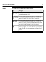
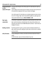
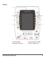
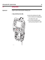
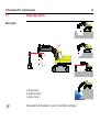
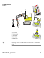
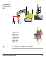
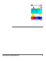
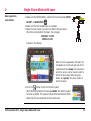
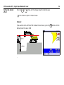
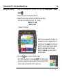
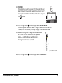
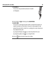
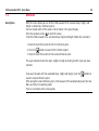
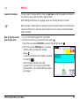
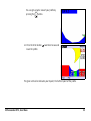
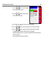
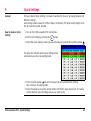
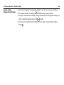
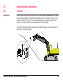
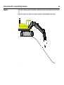
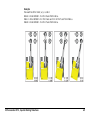
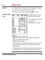
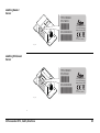
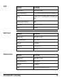
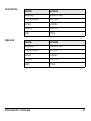
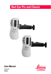
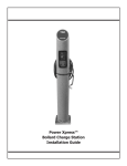
Leica iCON excavate iCP31 User Manual Version 1.1 English iCON excavate iCP31, Introduction 2 Introduction Purchase Congratulations on your purchase of iCON excavate iCP31 machine control system. iCON excavate iCP31 System is an ideal tool for increasing productivity in all aspects of the construction earthmoving industry. This manual contains important safety directions as well as instructions for setting up the system and operating it. Refer to chapter "13 Safety Directions" for further information. Read carefully through the User Manual before you switch on the product. To ensure safety when using the system, please also observe the directions and instructions contained in the User Manual and Safety Handbook issued by the: • Machine manufacturer, • Controller manufacturer and • Sensor manufacturer. Product identification The type and serial number of your products are indicated on the label on the base of the unit. Enter the model and serial number in your manual and always refer to this information when you need to contact your agency or Leica Geosystems authorised service workshop. Type: Control Box Serial No.: _________________________ Type: Cradle Serial No.: _________________________ Type: Junction Box Serial No.: _________________________ Type: Boom 1 Sensor Serial No.: _________________________ Type: Stick/Laser Sensor Serial No.: _________________________ Type: Bucket Sensor Serial No.: _________________________ Type: Rotation Sensor Serial No.: _________________________ Type: Can Junction Box Serial No.: _________________________ Type: Boom 2 Sensor Serial No.: _________________________ Type: Tilt Bucket Sensor Serial No.: _________________________ Type: Remote Display Serial No.: _________________________ iCON excavate iCP31, Introduction 3 iCON excavate iCP31, Introduction Symbols 4 The symbols used in this manual have the following meanings: Type Description Danger Indicates an imminently hazardous situation which, if not avoided, will result in death or serious injury. Warning Indicates a potentially hazardous situation or an unintended use which, if not avoided, could result in death or serious injury. Caution Indicates a potentially hazardous situation or an unintended use which, if not avoided, may result in minor or moderate injury and/or appreciable material, financial and environmental damage. Important paragraphs which must be adhered to in practice as they enable the product to be used in a technically correct and efficient manner. About This Manual iCON excavate iCP31 The iCON excavate iCP31 System is a basic machine control system that provides the operators with a visual reference of the bucket position. The iCON excavate iCP31 Control Box is designed to be easy to use and provides the operator with a range of information and setups to assist in all aspects of machine control. Major components The iCON excavate iCP31 System consists of several components depending on the type of machine and the customers needs to perform their earthmoving tasks. The basic components of the systems are the iCON excavate iCP31 Control Box, angle sensors, and cabeling. Purpose of this manual The purpose of this manual is to explain the features and operation of the iCON excavate iCP31 System. The specific uses of the systems are varied. This manual is not intended to teach each specific use. iCON excavate iCP31, About This Manual 5 iCON excavate iCP31, Table of Contents 6 Table of Contents In this manual Topic 1 Page System Overview 1.1 1.2 1.3 1.4 1.5 Product Description and Features Getting Started Single Slope System Dual Slope System Tilt Slope System 9 9 16 18 20 22 2 Setting the Direction of X 25 3 Single Slope Mode without Laser 31 4 Single Slope Mode with Laser 33 5 Dual Slope Mode 37 6 User Menu Tree 41 7 User Menu 43 7.1 7.2 7.3 7.4 7.5 7.6 7.7 7.8 7.9 43 44 45 51 52 53 59 60 60 SETUP SYSTEM SETUP HEIGHT SETUP BUCKET DUAL SLOPE MEASURE PROFILE CABLE DETECTION 3D/GPS MODE SERVICE MENU 8 Reversed Bucket 61 9 Quick Settings 63 10 Special Working Situations 65 10.1 10.2 65 67 Tilt Sensor Using an Auger 11 Diagnose Screen 71 12 Care and Transport 73 12.1 12.2 12.3 12.4 73 73 74 74 iCON excavate iCP31, Table of Contents General Notices Transport Storage Cleaning and Drying 7 iCON excavate iCP31, Table of Contents 13 14 15 8 Safety Directions 75 13.1 13.2 13.3 13.4 13.5 13.6 13.7 75 76 78 79 80 84 86 General Intended Use Limits of Use Responsibilities Hazards of Use Electromagnetic Compatibility EMC FCC Statement, Applicable in U.S. Technical Data 93 14.1 14.2 14.3 93 94 98 Accuracy of the System General Technical Data Conformity to National Regulations International Limited Warranty, Software Licence Agreement 99 1 System Overview 1.1 Product Description and Features General The iCON excavate iCP31 System from Leica Geosystems consists of a iCON excavate iCP31 Control Box with a varying number of sensors depending on which system is installed on the excavator. The control box has buttons surrounding the screen for user input. The 3.5" colour display, incorporates a state of the art LCD colour screen, making it easy to use, even in bright, sunny conditions. The iCON excavate iCP31 System is very easy to upgrade from e.g. Single Grade to Dual Grade. You just need to add the requisite sensors to your excavator. Please contact your local dealer for details. The rugged IP67 enclosure is designed for harsh environments. Warning Warning This product may be installed on building machinery only by an appropriately trained and qualified specialist. Unauthorised modification of machines by mounting the product may alter the function and safety of the machine. Precautions: Follow the instructions of the machine manufacturer. If no appropriate instruction is available, ask machine manufacturer for instructions before mounting the product. iCON excavate iCP31, System Overview 9 iCON excavate iCP31, System Overview The general principle of the iCON excavate iCP31 System 10 The sensors feed information to the iCON excavate iCP31 Control Box which makes the calculations. You just establish a known reference point, for example Laser beam or stake, and then enter the required offset and grade after which you are ready to start digging. On the iCON excavate iCP31 Control Box you can overlook all guidance and status information on the LCD display. Bright numbers and possibility for guidance by audio signals also make you able to determine if you are HIGH, ON GRADE or LOW. Power supply, communication The control box is powered from a cradle based on a sophisticated induction solution, while data is transferred wirelessly via infrared between the cradle and the control box. Leica Geosystems recommends to use the "MMB1300 Cradle for control box". "Cradle" will be used throughout this manual. Handling precautions The iCON excavate iCP31 System is a precision system and should be treated with care. When using the system with a rotating laser, please make sure that the laser is calibrated and set up correctly. Safety information If using a rotating laser as reference, do not stare into the laser beam when the laser is working. For more information, please see the documentation of your laser. iCON excavate iCP31 Control Box a b b BUCKET02 0.00 OFFSET c c -3.00 11.9% Y-SLOPE SLOPE 12.0% Q-set REACH 1.00 X-dir SLOPE X-SLOPE 5.0% d iCP31_001 a) b) c) d) Graphical display Offset indication LED’s Setup buttons Speaker iCON excavate iCP31, System Overview e f g e) Selection of bucket f) Function buttons g) Navigation button 11 iCON excavate iCP31, System Overview Description of buttons Button 12 Description Increases/decreases slope in Y-direction. Increases/decreases slope in X-direction. Increases/decreases offset. Load and Store height. Reset button. Used for setting the reference level and resetting earlier values in the menu. Selecting a bucket. Navigation button. Allows you to navigate through the menus. Press left/right arrows to move between bucket items. Naming convention within this manual: • : Enter button • : Left / Right arrow buttons • : Up / Down arrow buttons Quick settings. Up to 10 user settings can be stored. X-direction. Used for setting the X-direction. LED Display a b b c c d d iCP31_002 a) Tilt / Bucket indication b) Position of the bucket is HIGH iCON excavate iCP31, System Overview c) Position of the bucket is ON-GRADE d) Position of the bucket is LOW 13 iCON excavate iCP31, System Overview LCD Display 14 a b BUCKET02 0.00 c OFFSET -3.00 d e f g h i j k l 11.9% Y-SLOPE SLOPE 12.0% Q-set m REACH 1.00 X-dir X-SLOPE SLOPE 5.0% n a) Height measurement direction: NORMAL / VERTICAL b) Reference Method: LASER / BUCKET c) Direction of X d) Tilt Slope display: Active when Tilt Sensor is connected e) Actual Bucket Slope f) Y Slope g) Quick Settings h) Setting Direction of X i) Selected bucket j) Distance to ONGRADE k) Desired OFFSET l) Bucket position display m) Reach measurement n) X Slope Cradle a iCP31_003 iCON excavate iCP31, System Overview b d c a) b) c) d) Power and data transfer LED indicators Holding magnets On/off switch Release button for control box 15 iCON excavate iCP31, System Overview 16 1.2 Getting Started System start To get the system started complete the following steps: 1. Snap control box onto cradle. 2 1 1 iCP31_004 To connect the control box to the cradle: 1. Put the control box on the holding hooks in the bottom of the cradle. 2. Then snap the control box onto the cradle by pressing it towards the cradle. 2. Turn on the control box. To turn the system on and off, use the power switch on the right side of the cradle. This is the master switch for the entire system. Removing the box will also turn off the power. iCP31_005 2 To release the control box simply press the release button at the bottom of the cradle, pull the control box towards you and then lift it away from the cradle. 1 iCON excavate iCP31, System Overview 17 iCON excavate iCP31, System Overview 1.3 18 Single Slope System Basic system c UP DIGIT INCL AL SENS INATI OR ON EXCAV FOR PIT CH ATOR BOOM 2 STICK BUCKET RUGBY 400 DG b a RUGBY 400 DG a) Bucket Sensor b) Stick/Laser Sensor c) Boom 1 Sensor On excavators with two booms, a sensor is mounted on each boom. Basic system with Articulated Boom d c UP DIGITAL O N INCLINATIFOR R SENSO EXCAVATOR PITCH BOOM 2 STICK BUCKET UP AL O N DIGITINATI FOR INCL O R SENS ATOR EXCAV CH PIT 2 BOOM STICK BUCKET RUGBY 400 DG b a a) b) c) d) RUGBY 400 DG Bucket Sensor Stick/Laser Sensor Boom 2 sensor Boom 1 sensor On excavators with 2 booms, a sensor is mounted on each boom. iCON excavate iCP31, System Overview 19 iCON excavate iCP31, System Overview 1.4 20 Dual Slope System Pro system c d UP DIGIT INCL AL SENS INATI OR ON EXCAV FOR PIT CH ATOR BOOM 2 STICK BUCKET RUGBY 400 DG b a a) b) c) d) Bucket Sensor Stick/Laser Sensor Boom 1 Sensor Rotation Sensor Besides being a rotation sensor, the Rotation Sensor also functions as a Pitch and Roll sensor. Pro system with Articulated boom d c e UP DIGITAL O N INCLINATIFOR R SENSO EXCAVATOR PITCH BOOM 2 STICK BUCKET UP AL O N DIGITINATI FOR INCL O R SENS ATOR EXCAV CH PIT 2 BOOM STICK BUCKET RUGBY 400 DG b a a) b) c) d) e) Bucket Sensor Stick/Laser Sensor Boom 2 Sensor Boom 1 Sensor Rotation Sensor Besides being a rotation sensor, the Rotation Sensor also functions as a Pitch and Roll sensor. iCON excavate iCP31, System Overview 21 iCON excavate iCP31, System Overview 1.5 22 Tilt Slope System Pro system with Tilt slope e f RUGBY 400 DG d c UP XI S 1 DIGIT INCL AL SENS INATI OR ON EXCAV FOR PIT CH ATOR BOOM 2 STICK BUCKET b a a) b) c) d) e) f) Tilt Bucket Sensor Bucket Sensor CAN Junction box Stick/Laser Sensor Boom 1 Sensor Rotation Sensor Tilt The Tilt Bucket Sensor is connected via the CAN Junction Box. Pro system with Tilt slope and Articulated boom f e g UP DIGITAL O N INCLINATIFOR R SENSO EXCAVATOR PITCH BOOM 2 STICK BUCKET UP AL O N DIGITINATI FOR INCL O R SENS ATOR EXCAV CH PIT 2 BOOM STICK BUCKET d RUGBY 400 DG c b a a) b) c) d) e) f) g) Tilt Bucket Sensor Bucket Sensor CAN Junction box Stick/Laser Sensor Boom 2 Sensor Boom 1 Sensor Rotation Sensor Tilt The Tilt Bucket Sensor is connected via the CAN Junction Box. iCON excavate iCP31, System Overview 23 iCON excavate iCP31, System Overview 24 2 Setting the Direction of X Description The Direction of X is the main direction of the excavator boom. It is very important to set the Direction of X when working in Dual Slope Mode. There are two ways to set the Direction of X. The traditional way is to use one-point where the correct Direction of X is already known. The more advanced way is to use the two-point method. You can use this method when working with a string line for example. One-point method This is how you set the Direction of X using the one point method: 1. Press the button, which will open the Direction of X menu. 2. Select One-point method by pressing the up/down arrows . iCON excavate iCP31, Setting the Direction of X 25 iCON excavate iCP31, Setting the Direction of X 3. Turn the machine so that the boom points towards the Direction of X. 4. Press the Enter button to save the Direction of X. Two-point method This is how you set the X direction using the two point method: 1. Press the button, which will open the Direction of X menu. 2. Select Two-point method by pressing the up arrow . 3. Press the Enter button to enter the two point method. 26 4. Place the center of the bucket on point 1 (left side of the machine). 5. Press the Enter button to save point 1. a X b X a) Point 1 (left side of the machine) b) Point 2 (right side of the machine) iCON excavate iCP31, Setting the Direction of X 27 iCON excavate iCP31, Setting the Direction of X 28 6. Place the center of the bucket on point 2 (right side of the machine). 7. Press the Enter button to save point 2. The Direction of X has now been set to be exactly between the two points that were touched. a X b X a) Point 1 (left side of the machine) b) Point 2 (right side of the machine) iCON excavate iCP31, Setting the Direction of X 29 iCON excavate iCP31, Setting the Direction of X 30 3 Setting the desired offset Single Slope Mode without Laser 1. Make sure that LASER MODE is set to OFF (Bucket is selected as reference) in the menu option SETUP HEIGHT -> LASER MODE. 2. Press the or button until the display shows the desired offset value. Example If you want to enter a offset of 5.0 m, press the button until the display shows the value -5.00. The display to the right indicates: 1. The bucket selected is No. 1. 2. The value in red 5.00 indicates the distance to ONGRADE. 3. The desired offset is set to -5.00. 4. The X-slope is 0.0% (no slope). 5. The bucket tip is used as reference. 6. The distance is measured vertically . 7. REACH=-0.38 means that the bucket has been moved 38 cm closer to the machine since the button was pressed. iCON excavate iCP31, Single Slope Mode without Laser 31 iCON excavate iCP31, Single Slope Mode without Laser Digging with slope in X-direction Press the or 32 button until the display shows the slope desired. Example: If you want a slope where the excavation is getting shallower as the bucket comes nearer the excavator, press the right button until the display shows the desired slope. Positive slope Moving the excavator 1. Make sure that OFF is selected in the menu option SETUP HEIGHT -> LASER MODE . 2. Put the bucket at a place that can be reached again after moving the excavator. 3. Press the button to store the position. The red display will flash to indicate that the position is stored. 4. Move the excavator and put the bucket at exactly the same place where the position above was stored. 5. Press the button again to load the position. 4 Basic operation instructions Single Slope Mode with Laser 1. Make sure that INTEGRATED is selected in the menu option SETUP HEIGHT -> LASER MODE . 2. Make sure that the rotation laser is activated. 3. Move the Laser Sensor, so that it can detect the laser beam. When the sensor detects the beam, the message NEW REF. @ 0.00 PRESS L/S KEY RUGBY 400 DG is shown in the display. BUCKET02 0.00 OFFSET -3.00 11.9% Y-SLOPE SLOPE 12.0% Q-set 4. Press the REACH 1.00 X-dir X-SLOPE SLOPE 5.0% When the sensor approaches the beam, the LED-diodes on the left and right side of the control box will flash slowly in the direction in which the sensor is to be moved in order to detect the laser beam. When the green diodes flash quickly, the sensor is able to detect the beam. button to set the reference point. When the display flashes the message LASER, the reference point has been accepted. The values of actual Offset and desired Offset depend on the actual position of stick and bucket. iCON excavate iCP31, Single Slope Mode with Laser 33 iCON excavate iCP31, Single Slope Mode with Laser Setting the desired offset Press the or 34 button until the display shows the desired value. The reference point is the laser beam. Example: If you want to enter a offset of 5.0 m below the laser beam, press the display shows the value -5.00. RUGBY 400 DG 2.00 m 3.00 m button until the Digging with slope in X-direction Press the or button until the display shows the slope desired. The slope you enter on the display must always be the same as the slope of the rotation laser. RUGBY 400 DG Example: If you want a slope of 2%, where the excavation is getting shallower as the bucket comes nearer the excavator, press the button until the display shows the value 2.0%. iCON excavate iCP31, Single Slope Mode with Laser 35 iCON excavate iCP31, Single Slope Mode with Laser Moving the excavator 36 1. Make sure that INTEGRATED is selected in the menu option SETUP HEIGHT -> LASER MODE . 2. Move the excavator to the desired location. 3. Move the Laser Sensor, so that it can detect the laser beam. When the sensor detects the beam, the message NEW REF. @. 0.00 PRESS L/S KEY is shown in the display. BUCKET02 0.00 OFFSET -3.00 11.9% Y-SLOPE SLOPE 12.0% Q-set 4. Press the REACH 1.00 X-dir X-SLOPE SLOPE 5.0% When the sensor approaches the beam, the LED-diodes on the left and right side of the control box will flash slowly in the direction in which the sensor is to be moved in order to detect the laser beam. When the green diodes flash quickly, the sensor is able to detect the beam. button to set the reference point. When the display flashes the message LASER, the reference point has been accepted. The values of actual Offset and desired Offset depend on the actual position of stick and bucket. 5 Description Dual Slope Mode 1. Turn on the display. 2. Press the Enter button . You will now enter the User Menu. 3. Press the right arrow to select the option DUAL SLOPE. 4. Press the up arrow to turn DUAL SLOPE ON or OFF. 5. Leave the User Menu by pressing the button. 6. Adjustment of Y slope. Press the or button until the display shows the desired value. 7. Setting the Direction of X. Turn the machine so that the bucket points towards the Direction of X. Press the button, which sets the Direction of X . It is very important to set the Direction of X in Dual Slope Mode. 8. Adjustment of X slope. Press the or button until the display shows the desired value. 9. Adjust the offset underneath the laser beam by pressing the or button until the display shows the desired value. iCON excavate iCP31, Dual Slope Mode 37 iCON excavate iCP31, Dual Slope Mode 38 The display to the right indicates: 1. The bucket selected is No. 1. 2. The value in red 4.14 indicates the distance to ONGRADE. 3. The desired offset is set to -5.00. 4. The X-slope is 4.0 %. 5. REACH=-0.61 means that the bucket has been moved 61 cm closer to the machine since the button was pressed. 6. The Y-slope is 1.0 %. 7. A laser beam is used as reference . 8. The distance is measured vertically Example . The laser (blue) is adjusted to the following slopes 4.0 % in the X direction and 1.0 % in the Y direction. 1. Turn on the display. 2. Press the Enter button User Menu. . You will now enter the 3. Select DUAL SLOPE by pressing the right arrow . 4. Select ON by pressing the up arrow . 5. Leave the Menu by pressing the button. 6. Set the desired Y Slope by pressing the or button. (1.0%) Positive slope if the excavation gets deeper from the machine and to the right. 7. Turn the machine so that the bucket points to the direction of X. Press the 8. Press the button. or button until the display shows the desired value for X Slope. (4.0%) Positive slope if the excavation gets deeper from the machine and towards the bucket. 9. Adjust the offset underneath the laser beam by pressing the or button until the display shows the desired value. 10. Move the Laser Sensor so that it can detect the laser beam. When the display reads NEW REF. @. 0.00 PRESS L/S BUTTON you must press the button and you can start digging with Dual Slope. 11. iCON excavate iCP31 remembers the X direction, so you do not have to change the setting for X direction until you have a task for which the direction of X differs from the present setting. iCON excavate iCP31, Dual Slope Mode 39 iCON excavate iCP31, Dual Slope Mode 40 6 User Menu Tree User Menu tree |—— | | | | | | | |—— | | | | | | | | |—— | | | | | | | | | | | | | | SETUP SYSTEM |—— UNITS LENGTH |—— UNITS ANGLE |—— BEEP VOLUME |—— LIGHT INTENSITY |—— ALARM HEIGHT |—— REVERSED VIEW SETUP HEIGHT |—— GREENBAND MODE |—— GREENBAND |—— YELLOWBAND |—— YELLOW BEEP |—— REFERENCE OFFSET |—— HEIGHT DIRECTION |—— LASER MODE SETUP BUCKET |—— CALIBRATE BUCKET |—— ^v SELECT BUCKET | |—— TOOL TYPE | |—— BUCKET LEFT/RIGHT | |—— TILT | |—— BUCKET LEN | |—— BUCKET ANGLE | |—— BUCKET FLAT ANGLE | |—— BUCKET WIDTH | |—— TILT ZERO | |—— AUGER LENGTH | |—— DOG BONE L4 | |—— BUCKET NAME | | iCON excavate iCP31, User Menu Tree 41 iCON excavate iCP31, User Menu Tree | | | | | |—— | | |—— | | |—— | | |—— | | | | | | | |—— | |—— |—— |—— |—— |—— BUCKET POINT BUCKET INDICATOR BUCKET GREENBAND TILT GREENBAND DUAL SLOPE MEASURE PROFILE CABLE DETECTION |—— MODE |—— RANGE MIN |—— RANGE MAX |—— RESPONSE |—— ALARM |—— VOLUME 3D/GPS MODE SERVICE MENU* * Password protected menu for support personnel only. 42 7 User Menu Enter the User Menu To enter the User Menu, press the Enter button . Select a menu option by pressing the left/right arrows Press the Enter button to enter the sub-menus. Change a value by pressing the up/down arrows . . 7.1 SETUP SYSTEM UNITS LENGTH This menu option is used to set in which unit the length is measured. You can choose between meters, inches or feet. UNITS ANGLE This menu option is used to set in which unit the angle is measured. You can choose between per cent, per thousand, gon, degrees or relative. BEEP VOLUME This menu option is used to set how loud the iCON excavate iCP31 Control Box is to beep. You can choose between off, low, normal and loud. LIGHT INTENSITY This menu option is used to set the light intensity in the display. You can choose between the values from 0 to 15. ALARM HEIGHT This menu option is used to set how high up the pivot points are allowed to get. The value is the distance from the lowest pivot point. You can save the value by moving the bucket to a desired alarm height and pressing the button. iCON excavate iCP31, User Menu 43 iCON excavate iCP31, User Menu 44 REVERSED VIEW This menu option is used to reverse the view. You can choose between OFF or ON. 7.2 SETUP HEIGHT GREENBAND MODE This menu option is used to set the position of the greenband centred, above or below, the defined on grade level. Greenband is the interval in which the green light flashes. GREENBAND This menu option is used to set when the green diode/diodes in the middle of the remote display and on the Control Box respectively start to light. The value is the distance from when the green diodes start to light until when the red arrow and diode start to light. YELLOWBAND This menu option is used to set when the yellow diodes on the remote display and on the Control Box respectively start to light. The value is the distance from when the yellow diodes start to light until when the green diodes start to light. YELLOW BEEP This menu option is used to enable or disable the audible indication of being in the yellow band. REFERENCE OFFSET This menu option is used to set the reference height when the HEIGHT DIRECTION The iCON excavate iCP31 is capable of measuring the height of the bucket point over the defined on grade plane either strictly vertical or normal to the defined on grade plane. Use this option to set the desired height direction. You can choose between NORMAL and VERTICAL. LASER MODE This menu option is used to choose the nulling method. You can choose between OFF and INTEGRATED. • For OFF, the method is as described in section "3 Single Slope Mode without Laser". • For INTEGRATED, the method is as described in section "4 Single Slope Mode with Laser". 7.3 SETUP BUCKET CALIBRATE BUCKET In order to calibrate the bucket sensor, you must input some information about the length and angles of the bucket to the iCON excavate iCP31 System. button is pressed. Follow the instructions below to do so: 1. Press the Enter button . You will now enter the User Menu. 2. Select the menu option SETUP BUCKET. You select a menu option by pressing the left/right arrows . 3. Press the Enter button to enter the menu option CALIBRATE BUCKET. 4. Press the Enter button to enter the menu option ^v SELECT BUCKET. 5. Select the bucket you want to calibrate . It is possible to select between 30 buckets. iCON excavate iCP31, User Menu 45 iCON excavate iCP31, User Menu 46 6. Press the right arrow to enter the menu option TOOL TYPE. Select which tool type you want to calibrate, Bucket or Auger. 7. Press the right arrow to enter the menu option BUCKET LEFT/RIGHT. 8. Select whether the bucket sensor is placed left or right. . When making your choice, you must look on the lid of the sensor. If the lid is turned against the left side, then you must choose LEFT and vice versa. Note: if you choose the wrong side, the bucket and the graphics will work upside down. 9. Press the right arrow until the display shows TILT. 10. Select “NO” if the bucket is not a tilt bucket. Otherwise, select which tilt unit to use with the bucket. The system allows you to associate any one out of 5 tilt units to each bucket. Tilt units can be used with several buckets which is relevant when using a tilt coupling. 11. Press the right arrow until the display shows option BUCKET LEN. 12. Measure the distance between the pivot point of the bucket and the edge of the bucket. a a) BUCKET LEN 13. Press the up/down arrows until the display shows the distance between the pivot point and the edge of the bucket (BUCKET LEN) that you have measured in step 12. 14. Press the right arrow until the display shows BUCKET ANGLE. 15. Move the bucket of the excavator to a position where the line between the pivot point of the bucket and the edge of the bucket is in a straight vertical plane. To make sure that the line is in a straight vertical plane, we recommend that you use a spirit level. In calm weather, it is also possible to hold a plumb line to the pivot point and let it hang straight down. Then a move the bucket until the leading edge touches the string. 16. Press the a) BUCKET ANGLE button when the bucket is in the position described before in step 15. 17. Press the right arrow until the display shows BUCKET FLAT ANGLE. 18. Move the bucket of the excavator to a position where the bucket can be used to level the surface evenly. (This part of the calibration is used to set how the movements of the bucket are shown on the Control Box. The position you put the bucket into will correspond to the middle diode of the Bucket Angle Indicator on the Control Box. See section LED Display in the Chapter System Overview.) a a) BUCKET FLAT ANGLE 19. Press the iCON excavate iCP31, User Menu button when the bucket is in the position described before in step 18. 47 iCON excavate iCP31, User Menu 48 You can mount a reversed Bucket. Calibrate the reversed Bucket as normal and the graphic will reverse the Bucket on the screen. "Standard" bucket view "Reversed" bucket view 20. Press the right arrow until the display shows BUCKET WIDTH. 21. BUCKET WIDTH Measure the bucket width and press the up/down arrows until the display reads the width. The bucket sensor has now been calibrated. a a) BUCKET WIDTH 22. Press the right arrow until the display shows TILT ZERO. 23. TILT ZERO This sub-menu is used to calibrate the tilt bucket this way: Move the bucket to a position where the bucket is level 0°. Use a spirit level to check that the bucket is level and press the button. 0° 24. Press the right arrow until the display shows AUGER LENGTH. This menu option is only used when an Auger is attached to the machine. If an Auger is not attached, then Auger Length should be set to 0.000 25. Measure the length of the auger from the swivel joint to the tip of the drill bit and press the up/down arrows until the display reads the length. The Auger has now been calibrated. a) AUGER LENGTH 26. Press the right arrow iCON excavate iCP31, User Menu until the display shows DOG BONE L4. 49 iCON excavate iCP31, User Menu 50 27. DOG BONE L4 This sub-menu is only used when bucket sensor is mounted on the dog bone. 28. Press the right arrow until the display shows BUCKET NAME. 29. BUCKET NAME This sub-menu is used to give the various buckets a name after they have been calibrated. If you state @ as the first letter in the name, the iCON excavate iCP31 will generate the names BUCKET 1, BUCKET 2 etc. according to the number of buckets you have calibrated to the system. By pressing the left/right arrows , you can move the position of the cursor. By pressing the up/down arrows , you can change the letter. 30. Press the button three times to leave the User Menu. BUCKET POINT At this option you choose which bucket point is used for height measurements. You can choose between 5 settings: • MIDDLE, LEFT or RIGHT side of the bucket as reference point. The chosen bucket point is shown with a green indication. a There are 2 other possibilities where the bucket point automatically changes between: • Closest: the bucket point that is closest to the surface, or • Lowest: the bucket point that is lowest without regard to the surface. a) Closest The chosen bucket point is shown with a blue indication. b b) Lowest BUCKET INDICATOR Enables or disables the bucket and tilt angle indicators. BUCKET GREENBAND Sets the sensitivity of the bucket angle indicator. TILT GREENBAND Sets the sensitivity of the tilt angle indicator. This means how fast you want the lamps in the Tilt Slope display to react. 0.5% corresponds to an accuracy of about ± 2 cm working with a bucket of 1 m. 7.4 DUAL SLOPE Description Turns the dual slope mode of the iCON excavate iCP31 on or off. Dual slope operation is described in section "5 Dual Slope Mode". iCON excavate iCP31, User Menu 51 iCON excavate iCP31, User Menu 52 7.5 MEASURE Description With this menu option you can let the iCON excavate iCP31 calculate slope, height, and length in relation to 2 reference points. You can choose which of the values is to be shown in the upper display. Press the up/down arrows to select the value. To let the iCON excavate iCP31 calculate slope, height and length, follow this procedure: 1. Place the tip of the bucket on the first reference point. 2. Press the button to save the first reference point. 3. Place the tip of the bucket on the second reference point. The upper blue box shows the slope, height or length according to which value you have selected. If you want to work with the calculated slope, height and length, press the button to save the second reference point. After saving the second reference point, iCON excavate iCP31 automatically leaves the User Menu and returns to working mode. There is no timeout at this menu option. 7.6 PROFILE General information The basic idea of making profiles is either to copy/save a job that is already carried out or to pre-define various distances with a slope to match. After defining the distances or copying a job you can then dig the job at a stretch. How to copy/save a job that already exists When you work in profile mode, you will only be able to work with slope in one direction and a laser as reference line cannot be used. So before you start, make sure that Dual Slope mode is disabled. 1. Turn on the iCON excavate iCP31 Control Box. 2. Enter the User Menu by pressing the Enter button . 3. Select the menu option PROFILES by pressing the left/right arrows 4. At the menu option PROFILES you can select a profile number by pressing the up/down arrows . A small icon will indicate which profile is activated, for example P 1 . Profile number 0 indicates that iCON excavate iCP31 is not running in profile mode. Profile number 11 is a Demo profile that cannot be changed. iCON excavate iCP31, User Menu . 53 iCON excavate iCP31, User Menu 54 5. When you have selected a profile from 1 – 10, press the Enter button to activate the selected profile. 6. Place the bucket at the farthest point of the profile you want to copy/save. 7. Press the button to LOG/Save this point as the first point of the profile. 8. Place the bucket at the second farthest point of the profile. 9. Press the button to save this point as the second point. The slope and distance between the points is shown in the display. 10. Place the bucket at the third farthest point of the profile. 11. Press the button to save this point as the third point. The slope and distance between the points is shown in the display. 12. Place the bucket at the fourth farthest point of the profile. 13. Press the button to save this point as the fourth point. The slope and distance between the points is shown in the display. Continue this operation until you have saved all points in your profile. You can save up to 10 points in a profile. You can get a graphic view of your profile by pressing the button. 14. Press the Enter button leave the profile. two times to save and The green vertical line indicates your 0-point, the farthest point of the profile. iCON excavate iCP31, User Menu 55 iCON excavate iCP31, User Menu 56 The 0-point can be moved the following way: Enter the profile. Use the up/down arrows to move the red bar to the point that you want to be your new 0-point. Press the • • • button (SET 0.0). The green area indicates that this area is included in the profile, and your bucket is working in this area right now. The blue area indicates that this area is included in the profile, but your bucket is not working in this area right now. The red area indicates that this area is NOT included in the profile. When you are at the Main Screen, you can press the button to enter the settings of the selected profile. How to set up/change a profile by stating the length and slope 1. Turn on the iCON excavate iCP31 Control Box. 2. Enter the User Menu by pressing the Enter button . 3. Select the menu option PROFILES by pressing the left/right arrows 4. At the menu option PROFILES you can select a profile number by pressing the up/down arrows . A small icon will indicate which profile is activated, for example P 1 . Profile number 0 indicates that iCON excavate iCP31 is not running in profile mode. Profile number 11 is a Demo profile that cannot be changed. . 5. When you have selected a profile from 1 – 10, press the Enter button to activate the selected profile. 6. Press the right arrow iCON excavate iCP31, User Menu to set up/change the selected profile. 57 iCON excavate iCP31, User Menu 7. Press the 58 or button to state the length of the first stretch of the profile. 8. Press the or button to state the slope of the first stretch of the profile. 9. Press the down arrow to get to the next stretch of the profile. 10. Press the or button to state the length of the next stretch of the profile. 11. Press the or button to state the slope of the next stretch of the profile. The length and slope between the points are shown in the display. Repeat the procedures 10. and 11. until you have stated all the stretches you want to include in the profile. You can state up to 10 stretches in the profile. You can get a graphic view of your profile by pressing the left arrow and subsequently the button. 12. Press the Enter button two times to save and leave the profile. 7.7 CABLE DETECTION Description Please refer to the Cable Detection EZiDIG User Manual regarding the settings for CABLE DETECTION. iCON excavate iCP31, User Menu 59 iCON excavate iCP31, User Menu 60 7.8 3D/GPS MODE Description This menu option enables or disables 3D mode. In 3D mode, the iCON excavate iCP31 communicates with an external 3D machine control system to provide control of the excavator in three dimensions. When 3D MODE has been selected, the be shown in the display. icon will 7.9 SERVICE MENU Description Password protected menu for support personnel only. 8 Reversed Bucket Description You can mount a reversed bucket. Calibrate the reversed Bucket as standard bucket and the graphic will reverse the bucket on the screen. "Standard" bucket view iCON excavate iCP31, Reversed Bucket "Reversed" bucket view 61 iCON excavate iCP31, Reversed Bucket 62 9 Quick Settings General The basic idea of Quick Settings is to make it possible for the user to change between 10 different settings. Each setting includes values for: Offset, Slope in X-direction, Tilt Slope, Datum Height, Direction of X and the bucket selected. How to make a Quick Setting 1. Turn on the iCON excavate iCP31 Control Box. 2. Enter Quick Setting by pressing the button. 3. Select the Quick Setting number you want to make by pressing the up/down arrows . The green bar indicates which Quick Setting will be active when you return to working mode. 4. Press the Enter button to enter the values for the selected Quick Setting. You will return to working mode. 5. Enter the values by using the normal buttons for Offset, Slope, Bucket etc. The values will be stored as a Quick Setting and you can start to dig. iCON excavate iCP31, Quick Settings 63 iCON excavate iCP31, Quick Settings How to change between Quick Settings 1. Enter Quick Setting by pressing the 64 button. You will see a green and a red bar. 2. The red bar indicates the settings you had before entering Quick Setting. 3. The green bar indicates the settings that you will have when leaving Quick Setting and return to working mode by pressing the button. 4. To select a Quick Setting move the green bar up or down by pressing the up/down arrows . 10 Special Working Situations 10.1 Tilt Sensor Description Under special circumstances, you may experience that the option Tilt sensor cannot follow the right measure/height. This will affect the height value that is shown in the upper red display. The value will "jump". This can happen during a pull – please just ignore it and continue, the system will then settle back and show the right height. The above mentioned situation will appear when the Delta Angle is in vertical position ±5° like shown in the drawing below. ±5° iCON excavate iCP31, Special Working Situations 65 iCON excavate iCP31, Special Working Situations Solution • • 66 Move the machine closer to the profile, so that you do not have to open the bucket fully, or Move the machine on top of the profile, and work from the bottom to the top. 10.2 Using an Auger Explanation of the work screen • • • • • • • • • The drill bit tip will be shown as a circle and have the color Green (0-5 cm) or Red (+5 cm). The top point of the auger will be shown as a ring and have the color Blue (0-5 cm) or Orange (+5 cm). The inner part of the cross hairs will be highlighted when the drill bit and top of the drill is within the specified tolerance. The X and Y top tell you how far the top of the auger is from zero. The X and Y tell you how far the auger is from center. In the right top corner is the high shown relative to zero. In the lowest right corner you can see X and Y, this indicate how much you have moved the auger away from the first hole. If you move the auger 2 meters in the X direction and will drill a new hole the place the Auger 2-3 cm above the ground and press the F3 button. (center). The circle and the ring will now be on top of each other and you can start drill. iCON excavate iCP31, Special Working Situations 67 iCON excavate iCP31, Special Working Situations How to use the Auger 68 To use a Auger on your excavator, please follow the procedure below: 1. Place the auger over the first point you want to drill. 2. Press the X-dir button and set the direction. (Select 1 or 2 points option with the up or down arrows and press Enter). 3. Press the 0.00 button when the auger and direction are placed and set correct. 4. Start drilling. When drilling the next hole, just move the upper part of the excavator (not the tracks) and use the X and Y for placing the next hole. Press Center (F3) when the auger is placed correct, and then start drilling. The X and Y direction can be affected by iron objects around the machine. Example You want to drill 4 holes; a, b, c and d. Hole b is to be drilled 1 m in the X axis from hole a. Hole c is to be drilled 1 m in the X axis and 1 m in the Y axis from hole a. Hole d is to be drilled 1 m in the Y axis from hole a. iCON excavate iCP31, Special Working Situations 69 iCON excavate iCP31, Special Working Situations 1. Place the auger over hole a. 2. Press the X-dir button and set the direction. (Select 1 or 2 points option with the up or down arrows and press Enter). 3. Press the 0.00 button when the auger and direction are placed and set correct. 4. Start drilling. 5. Move the auger without moving the tracks of the machine until the display reads X: 1.00m and Y: 0.00m. 6. Press Center (F3). 7. Start drilling. 8. Move the auger without moving the tracks of the machine until the display reads X: 1.00m Y: 1.00m. 9. Press Center (F3). 10. Start drilling. 11. Move the auger without moving the tracks of the machine until the display reads X: 0.00m Y: 1.00m. 12. Press Center (F3). 13. Start drilling. 70 11 Diagnose Screen Description This is a diagnose tool to view the status of sensors and error messages. If a cable breaks or a sensor is dead, it is easily possible to verify where the problem is. To activate this screen, you must push the left/right arrows at the same time. Example of a diagnose screen On the diagnosis screen you can see a detailed system status information. The most important columns are the last two: ENAB and STAT. They will show if there is a deviation. • • • • ENAB tells the setting for the sensor that has been made in the technical menu. When the sensor is activated, YES will be shown. STAT tells if the sensor is working. ON shows that the sensor is working, OFF shows a failure either in the sensor or in the cable connection from the previous sensor - this is meant from the cabin and out towards the bucket. * tells that the Bucket Sensor needs to be recalibrated. Please contact your local dealer. ! tells that the Tilt Sensor is not working correctly. Please contact your local dealer. iCON excavate iCP31, Diagnose Screen 71 iCON excavate iCP31, Diagnose Screen 72 12 Care and Transport 12.1 General Notices General information Servicing the system only requires a minimum of time. All electronic components are enclosed in robust housings to safeguard them against mechanical damage. Periodic checks If any iCON excavate iCP31 components are subjected to severe impact, be sure to check for proper operation prior to performing any work with the system. 12.2 Transport Transport in the field When transporting the equipment in the field, always make sure that you carry the product in its original transport container. Transport in a road vehicle Never carry the product loose in a road vehicle. It can be affected by shock and vibration. Always carry the product in its transport container and secure it. Shipping When transporting the product by rail, air or sea, always use the complete original Leica Geosystems packaging transport container and cardboard box, or its equivalent, to protect against shock and vibration. Field adjustment After transport inspect the field adjustment parameters given in this user manual before using the product. iCON excavate iCP31, Care and Transport 73 iCON excavate iCP31, Care and Transport 74 12.3 Storage Product Respect the temperature limits when storing the equipment, particularly in summer if the equipment is inside a vehicle. Refer to "14 Technical Data" for information about temperature limits. Field adjustment After long periods of storage inspect the field adjustment parameters given in this user manual before using the product. 12.4 Cleaning and Drying Product • • • Blow off dust. Use a clean, soft, lint-free cloth for cleaning. If necessary, moisten the cloth with water or pure alcohol. Do not use other liquids; these may attack the polymer components. Cables and Plugs • • Keep plugs clean and dry. Blow away any dirt lodged in the plugs of the connecting cables. Damp products • • Dry the products at a temperature not greater than 40°C/108°F and clean them. Do not repack until everything is completely dry. 13 Safety Directions 13.1 General Description The following directions should enable the person responsible for the product, and the person who actually uses the equipment, to anticipate and avoid operational hazards. The person responsible for the product must ensure that all users understand these directions and adhere to them. iCON excavate iCP31, Safety Directions 75 iCON excavate iCP31, Safety Directions 13.2 Intended Use Permitted use • • • • • • Adverse use • • • • • • • • • • • 76 Control of machine tool for generic working in height, slope, and if present, side shift, based on reference height, reference line, and machine geometry. Detection of machine geometry by machine-mounted slope and rotation sensors. Detection of a desired reference height and/or slope by laser or sonic sensors. Recording measurements. Computing by means of application software. Guidance of the operator. Use of the product without instruction. Use outside of the intended limits. Disabling safety systems. Removal of hazard notices. Opening the product using tools, for example screwdriver, unless this is specifically permitted for certain functions. Modification or conversion of the product. Use after misappropriation. Use of products with obviously recognizable damages or defects. Use with accessories from other manufacturers without the prior explicit approval of Leica Geosystems. Inadequate safeguards at the work site, for example working on roads. Controlling of machines, moving objects or similar monitoring application without additional control- and safety installations. Warning Warning Adverse use can lead to injury, malfunction and damage. It is the task of the person responsible for the equipment to inform the user about hazards and how to counteract them. The product is not to be operated until the user has been instructed how to work with it. Unauthorised modification of machines by mounting the product may alter the function and safety of the machine. Precautions: Follow the instructions of the machine manufacturer. If no appropriate instruction is available, ask machine manufacturer for instructions before mounting the product. iCON excavate iCP31, Safety Directions 77 iCON excavate iCP31, Safety Directions 78 13.3 Limits of Use Environment Suitable for use in an atmosphere appropriate for permanent human habitation: not suitable for use in aggressive or explosive environments. Danger Local safety authorities and safety experts must be contacted before working in hazardous areas, or in close proximity to electrical installations or similar situations by the person in charge of the product. 13.4 Responsibilities Manufacturer of the product Leica Geosystems AG, CH-9435 Heerbrugg, hereinafter referred to as Leica Geosystems, is responsible for supplying the product, including the user manual and original accessories, in a completely safe condition. Manufacturers of nonLeica Geosystems accessories The manufacturers of non-Leica Geosystems accessories for the product are responsible for developing, implementing and communicating safety concepts for their products, and are also responsible for the effectiveness of those safety concepts in combination with the Leica Geosystems product. Person in charge of the product The person in charge of the product has the following duties: • To understand the safety instructions on the product and the instructions in the user manual. • To be familiar with local regulations relating to safety and accident prevention. • To inform Leica Geosystems immediately if the product and the application becomes unsafe. Warning Warning The person responsible for the product must ensure that it is used in accordance with the instructions. This person is also accountable for the training and the deployment of personnel who use the product and for the safety of the equipment in use. This product may be installed on building machinery only by an appropriately trained and qualified specialist. iCON excavate iCP31, Safety Directions 79 iCON excavate iCP31, Safety Directions 13.5 Warning Caution Warning Warning 80 Hazards of Use Only Leica Geosystems authorised service workshops are entitled to repair these products. Installing near mechanically moving machine components may damage the product. Precautions: Deflect the mechanically moving machine components as far as possible and define a safe installation zone. Beware of inadequate steering if machine is defective like after a crash or other damaging events or alterations to the machine. Precautions: Periodically perform control measurements and field adjustments on the machine as specified in the User Manual. While working, construction and grading should be checked by appropriate means, for example spirit level, tachymeter, before and after important measuring tasks. While steering or navigating the machine accidents may occur due to a) the operator not paying attention to the surroundings (persons, ditches, traffic, etc.), or b) malfunctions (…of a system component, interference, etc). Precautions: The operator assures that the machine is operated, guided and monitored by a qualified user (e.g. driver). The user has to be able to take emergency measures, for example an emergency stop. Warning Caution Danger Warning The absence of instruction, or the inadequate imparting of instruction, can lead to incorrect or adverse use, and can give rise to accidents with far-reaching human, material, financial and environmental consequences. Precautions: All users must follow the safety directions given by the manufacturer and the directions of the person responsible for the product. Watch out for erroneous measurement results if the product has been dropped or has been misused, modified, stored for long periods or transported. Precautions: Periodically carry out test measurements and perform the field adjustments indicated in the user manual, particularly after the product has been subjected to abnormal use and before and after important operations. Because of the risk of electrocution, it is very dangerous to use poles and extensions in the vicinity of electrical installations such as power cables or electrical railways. Precautions: Keep at a safe distance from electrical installations. If it is essential to work in this environment, first contact the safety authorities responsible for the electrical installations and follow their instructions. If the product is used with accessories, for example masts, staffs, poles, you may increase the risk of being struck by lightning. Precautions: Do not use the product in a thunderstorm. iCON excavate iCP31, Safety Directions 81 iCON excavate iCP31, Safety Directions Warning Warning Warning Caution 82 During dynamic applications, there is a danger of accidents occurring if the user does not pay attention to the environmental conditions around, for example obstacles, excavations or traffic. Precautions: The person responsible for the product must make all users fully aware of the existing dangers. Inadequate securing of the working site can lead to dangerous situations, for example in traffic, on building sites, and at industrial installations. Precautions: Always ensure that the working site is adequately secured. Adhere to the regulations governing safety and accident prevention and road traffic. If computers intended for use indoors are used in the field there is a danger of electric shock. Precautions: Adhere to the instructions given by the computer manufacturer with regard to field use in conjunction with Leica Geosystems products. If the accessories used with the product are not properly secured and the product is subjected to mechanical shock, for example blows or falling, the product may be damaged or people may sustain injury. Precautions: When setting-up the product, make sure that the connecting cables, are correctly adapted, fitted, secured, and locked in position. Avoid subjecting the product to mechanical stress. Warning If the product is improperly disposed of, the following can happen: • If polymer parts are burnt, poisonous gas are produced which may impair health. • If batteries are damaged or are heated strongly, they can explode and cause poisoning, burning, corrosion or environmental contamination. • By disposing of the product irresponsibly you may enable unauthorised persons to use it in contravention of the regulations, exposing themselves and third parties to the risk of severe injury and rendering the environment liable to contamination. Precautions: The product must not be disposed with household waste. Dispose of the product appropriately in accordance with the national regulations in force in your country. Always prevent access to the product by unauthorised personnel. Product specific treatment and waste management information can be downloaded from the Leica Geosystems home page at http://www.leica-geosystems.com/treatment or received from your Leica Geosystems dealer. iCON excavate iCP31, Safety Directions 83 iCON excavate iCP31, Safety Directions 84 13.6 Electromagnetic Compatibility EMC Description The term Electromagnetic Compatability is taken to mean the capability of the product to function smoothly in an environment where electromagnetic radiation and electrostatic discharges are present, and without causing electromagnetic distur-bances to other equipment. Warning Caution Caution Electromagnetic radiation can cause disturbances in other equipment. Although the product meets the strict regulations and standards which are in force in this respect, Leica Geosystems cannot completely exclude the possibility that other equipment may be disturbed. There is a risk that disturbances may be caused in other equipment if the product is used in conjunction with accessories from other manufacturers, for example field computers, personal computers, two-way radios, non-standard cables or external batteries. Precautions: Use only the equipment and accessories recommended by Leica Geosystems. When combined with the product, they meet the strict requirements stipulated by the guidelines and standards. When using computers and two-way radios, pay attention to the information about electromagnetic compatibility provided by the manufacturer. Disturbances caused by electromagnetic radiation can result in erroneous measurements. Although the product meets the strict regulations and standards which are in force in this respect, Leica Geosystems cannot completely exclude the possibility that the product may be disturbed by very intense electromagnetic radiation, for example, near radio transmitters, two-way radios or diesel generators. Precautions: Check the plausibility of results obtained under these conditions. Warning If the product is operated with connecting cables attached at only one of their two ends, for example external supply cables, interface cables, the permitted level of electromagnetic radiation may be exceeded and the correct functioning of other products may be impaired. Precautions: While the product is in use, connecting cables, for example product to external battery, product to computer, must be connected at both ends. iCON excavate iCP31, Safety Directions 85 iCON excavate iCP31, Safety Directions 13.7 Warning Warning 86 FCC Statement, Applicable in U.S. This equipment has been tested and found to comply with the limits for a Class B digital device, pursuant to part 15 of the FCC rules. These limits are designed to provide reasonable protection against harmful interference in a residential installation. This equipment generates, uses and can radiate frequency energy and, if not installed and used in accordance with the instructions, may cause harmful interference to radio communication. However, there is no guarantee that interference will not occur in a particular installation. If this equipment does cause harmful interference to radio or television reception, which can be determined by turning the equipment off and on, the user is encouraged to try to correct the interference by one or more of the following measures: • Reorient or relocate the receiving antenna. • Increase the separation between the equipment and the receiver. • Connect the equipment into an outlet on a circuit different from that to which the receiver is connected. • Consult the dealer or an experienced radio/TV technician for help. Changes or modifications not expressly approved by Leica Geosystems for compliance could void the user's authority to operate the equipment. Labelling Control Box iCP31 Excavator 2D Panel P/N: 798667 797050 S/N: xxxxxxxx xxxxxxxx Leica Geosystems AG CH - 9435 Heerbrugg Made in Denmark 20XX Power 12 - 24 V DC, 6A max. iCP31_008 Labelling Cradle TYPE: MMB1300 P/N: 764910 764910 S/N: XXXXXXXX 131441XX Leica Geosystems AG CH - 9435 Heerbrugg Made in Denmark 20XX Power 12 - 24 V DC, 6A max. iCP31_009 iCON excavate iCP31, Safety Directions 87 iCON excavate iCP31, Safety Directions 88 Labelling Junction Box TYPE: XJB-16 P/N: 779080 779080 S/N: XXXXXXXX Leica Geosystems AG CH - 9435 Heerbrugg Made in Denmark 20XX 131441XX iCP31_010 Labelling Boom 1 Sensor TYPE: MSS300 P/N: 761693 761693 S/N: XXXXXXXX 131441XX iCP31_011 Leica Geosystems AG CH - 9435 Heerbrugg Made in Denmark 20XX Power 12 - 24 V DC, 6A max. Labelling Boom 2 Sensor TYPE: MSS304 P/N: 762316 762316 S/N: XXXXXXXX 131441XX Leica Geosystems AG CH - 9435 Heerbrugg Made in Denmark 20XX Power 12 - 24 V DC, 6A max. iCP31_012 Labelling Stick/Laser Sensor TYPE: MSS301 P/N: 761694 761694 S/N: XXXXXXXX 131441XX Leica Geosystems AG CH - 9435 Heerbrugg Made in Denmark 20XX Power 12 - 24 V DC, 6A max. iCP31_013 iCON excavate iCP31, Safety Directions 89 iCON excavate iCP31, Safety Directions 90 Labelling Bucket Sensor MSS310 360 deg. bucket sensor P/N: 795199 795199 S/N: XXXXXXXX 131441XX Leica Geosystems AG CH - 9435 Heerbrugg Made in Denmark 20XX Power 12 - 24 V DC, 6A max. iCP31_014 Labelling Compas and Pitch/Roll Sensor TYPE: MRS300 P/N: 761696 761696 S/N: XXXXXXXX 131441XX iCP31_015 Leica Geosystems AG CH - 9435 Heerbrugg Made in Denmark 20XX Power 12 - 24 V DC, 6A max. Labelling Can Junction Box TYPE: MJB300 P/N: 761697 761697 S/N: XXXXXXXX 131441XX Leica Geosystems AG CH - 9435 Heerbrugg Made in Denmark 20XX Power 12 - 24 V DC, 6A max. iCP31_016 Labelling Tilt Bucket Sensor MSS309 Tilt bucket sensor P/N: 795200 773698 S/N: 131441XX 131441XX Leica Geosystems AG CH — 9435 Heerbrugg Made in Denmark 20XX Power 12 — 24 V DC, 6A max. iCP31_017 iCON excavate iCP31, Safety Directions 91 iCON excavate iCP31, Safety Directions Labelling Remote Display 92 TYPE: MLB 300 P/N: 773702 773702 S/N: 131441XX 131441XX iCP31_018 Leica Geosystems AG CH - 9435 Heerbrugg Made in Denmark 20XX Power 12 - 24 V DC, 6A max. 14 Technical Data 14.1 Accuracy of the System Digging system dual slope Accuracy depends upon various factors including the calibration accuracy, the size of the machine, worn out joints, if the excavator is placed on stable ground. The accuracy of the system is 0.2 % of the reach of the machine, measured at the bucket point when the machine is positioned on a level surface. Accuracy of the rotation sensor Accuracy of the rotation sensor is 2° or better. iCON excavate iCP31, Technical Data 93 iCON excavate iCP31, Technical Data 14.2 Protection class Temperature Control Box 94 General Technical Data Unit Protection class Control Box IP67 All Sensors IP68 Cradle IP54 Junction Box IP68 Can Junction Box IP68 Unit Operating temperature [°C] Storage temperature [°C] All Units -20 to +70 -40 to +80 Parameter Specification Voltage range 24V DC Nominal Voltage Range 10V - 30V Current consumption <200mA @ 24VDC Graphic display 4” LCD colour screen Keypad 18 keys, with backlight Interfaces Infrared Dimensions 12.5 x 18 x 3.7 cm Weight 0.5 kg Cradle Bucket Sensor Stick/Laser Sensor Parameter Specification Voltage range 12/24 Volts dc (nom) Current consumption < 2.5A with control box connected and no load at 12 V Output 2 x RS232, RX, TX, 12V/2Amp, GND, 2 x MikroCAN and J1939 Communication (Infrared) 1 Mbit Dimensions 12.4 x 15.2 x 4.4 cm Weight 0.320 kg Parameter Specification Voltage range 12/24 Volts dc (nom) Current consumption 0,2A @ 24VDC Interfaces 1 x CAN M12 Dimensions 2.5 x 2.5 x 5 cm Weight 0.100 kg Parameter Specification Voltage range 12/24 Volts dc (nom) Current consumption 0,2A @ 24VDC Interfaces 2 x CAN M12 Range 19 cm to 150 m (depended on laser) iCON excavate iCP31, Technical Data 95 iCON excavate iCP31, Technical Data Tilt Bucket Sensor Rotation Sensor 96 Parameter Specification Laser requirement All Rotating Lasers (visible HeNe, invisible Infrared diodes Laser) Operating range 55 mm Dimensions 8 x 12 x 3 cm Weight 0.750 kg Parameter Specification Voltage range 12/24 Volts dc (nom) Current consumption 0,2A @ 24VDC Interfaces 1 x CAN M12 Dimensions 2.5 x 2.5 x 5 cm Weight 0.100 kg Parameter Specification Voltage range 12/24 Volts dc (nom) Current consumption 0,2A @ 24VDC Interfaces 2 x CAN M12 Dimensions ø 7 cm, height incl. Mast: 80 cm Weight 0.500 kg Can Junction Box Angle sensor Parameter Specification Voltage range 12/24 Volts dc (nom) Current consumption 0,2A @ 24VDC Interfaces 2 x CAN M12 Dimensions 8 x 12 x 3 cm Weight 0.750 kg Parameter Specification Voltage range 12/24 Volts dc (nom) Current consumption 0,2A @ 24VDC Interfaces 2 x CAN M12 Dimensions 8 x 12 x 3 cm Weight 0.750 kg iCON excavate iCP31, Technical Data 97 iCON excavate iCP31, Technical Data 14.3 Conformity to national regulations 98 Conformity to National Regulations Hereby, Leica Geosystems AG, declares that the iCON excavate iCP31 Control Box is in compliance with the essential requirements and other relevant provisions of the applicable European Directives. The declaration of conformity may be consulted at http://www.leica-geosystems.com/ce. 15 International Limited Warranty, Software Licence Agreement International Limited Warranty This product is subject to the terms and conditions set out in the International Limited Warranty which you can download from the Leica Geosystems home page at http://www.leica-geosystems.com/internationalwarranty or collect from your Leica Geosystems distributor. The foregoing warranty is exclusive and is in lieu of all other warranties, terms or conditions, express or implied, either in fact or by operation of law, statutory or otherwise, including warranties, terms or conditions of merchantability, fitness for a particular purpose, satisfactory quality and non-infringement, all of which are expressly disclaimed. Software Licence Agreement This product contains software that is preinstalled on the product, or that is supplied to you on a data carrier medium, or that can be downloaded by you online pursuant to prior authorisation from Leica Geosystems. Such software is protected by copyright and other laws and its use is defined and regulated by the Leica Geosystems Software License Agreement, which covers aspects such as, but not limited to, Scope of the License, Warranty, Intellectual Property Rights, Limitation of Liability, Exclusion of other Assurances, Governing Law and Place of Jurisdiction. Please make sure, that at any time you fully comply with the terms and conditions of the Leica Geosystems Software License Agreement. Such agreement is provided together with all products and can also be referred to and downloaded at the Leica Geosystems home page at http://www.leica-geosystems.com/swlicense or collected from your Leica Geosystems distributor. You must not install or use the software unless you have read and accepted the terms and conditions of the Leica Geosystems Software License Agreement. Installation or use of the software or any part thereof, is deemed to be an acceptance of all the terms and conditions iCON excavate iCP31, International Limited Warranty, Software Licence Agreement 99 iCON excavate iCP31, International Limited Warranty, Software Licence Agreement 100 of such License Agreement. If you do not agree to all or some of the terms of such License Agreement, you may not download, install or use the software and you must return the unused software together with its accompanying documentation and the purchase receipt to the dealer from whom you purchased the product within ten (10) days of purchase to obtain a full refund of the purchase price. iCON excavate iCP31, International Limited Warranty, Software Licence Agreement 101 Ask your local Leica Geosystems dealer for more information about our TQM program. Leica Geosystems AG Heinrich-Wild-Strasse CH-9435 Heerbrugg Switzerland Phone +41 71 727 31 31 www.leica-geosystems.com Original text 798777-1.1.0en Leica Geosystems AG, Heerbrugg, Switzerland, has been certified as being equipped with a quality system which meets the International Standards of Quality Management and Quality Systems (ISO standard 9001) and Environmental Management Systems (ISO standard 14001). Printed in Switzerland © 2013 Leica Geosystems AG, Heerbrugg, Switzerland Total Quality Management: Our commitment to total customer satisfaction.