1
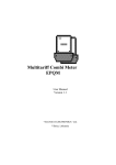
SingleSingle-Phase Static Meter Series
GAMA 100
User Manual
Version 2.2
2.2
“ELGAMA“ELGAMA- ELEKTRONIKA”, Lietuva 2010
2010
„ELGAMA – ELEKTRONIKA” Ltd.
SingleSingle-Phase Static Meter Series GAMA 100
User Manual
„ELGAMA – ELEKTRONIKA” Ltd.
2 Visoriu str.,
08300 Vilnius
Lithuania
Tel. +370 2 375000
Fax +370 2 375020
E-mail: [email protected]
4
Version
1.0
1.1
1.2
2.0
2.1
2.2
Date
2008-07-23
2008-10-09
2008-11-10
2009-07-14
2010-01-20
2010-05-03
Comments
Draft
First release
M-Bus added
G1S construction added
Error corrections
Description of functional possibility “V” added. Error corrections.
5
Table of contents
Table of contents ............................................................................................................................................ 6
List of tables.................................................................................................................................................... 7
List of figures................................................................................................................................................... 7
About this document ....................................................................................................................................... 8
1
Designation ............................................................................................................................................ 9
2
Meter variants......................................................................................................................................... 9
2.1
GAMA 100 meter constructions .................................................................................................... 9
2.2
Meter possibilities .......................................................................................................................... 9
2.3
Additional possibilities.................................................................................................................... 9
3
Technical characteristics...................................................................................................................... 12
4
Construction ......................................................................................................................................... 13
4.1
Meter case................................................................................................................................... 13
4.2
Operation principle ...................................................................................................................... 19
4.2.1
Measurement module ......................................................................................................... 19
4.2.2
Current measurement in neutral circuit............................................................................... 19
4.2.3
Signal conversion................................................................................................................ 19
4.2.4
Microcontroller .................................................................................................................... 19
4.2.5
Non-volatile memory........................................................................................................... 20
4.3
Liquid crystal display (LCD) ......................................................................................................... 20
4.4
Mechanical register ..................................................................................................................... 22
4.5
Internal clock (G1A)..................................................................................................................... 22
4.6
Communication interfaces........................................................................................................... 22
4.6.1
Optical interface .................................................................................................................. 22
4.6.2
Electrical interface............................................................................................................... 22
4.7
Outputs and inputs ...................................................................................................................... 23
4.7.1
Optical test output (red LED) .............................................................................................. 23
4.7.2
S0 outputs........................................................................................................................... 23
4.7.3
Relay output (optional, only G1A) ....................................................................................... 23
4.7.4
Tariff switch input (optional, only G1E) ............................................................................... 23
4.8
Power supply ............................................................................................................................... 23
4.9
Push buttons (G1A) ..................................................................................................................... 23
4.10
Changeable battery (only G1A) ................................................................................................... 24
4.11
Sliding voltage link ....................................................................................................................... 25
5
Tariff module (G1A).............................................................................................................................. 26
5.1
Tariff programs ............................................................................................................................ 26
5.2
Special day calendar ................................................................................................................... 27
6
Data reading......................................................................................................................................... 28
6.1
Manual data scrolling on the LCD (G1A)..................................................................................... 28
6.2
Cyclic data scrolling ..................................................................................................................... 31
6.3
Energy indication ......................................................................................................................... 31
6.4
Indication of instantaneous power (only G1A) ............................................................................. 31
6.5
Indication of failures..................................................................................................................... 31
6.6
Data reading via communication interfaces ................................................................................ 32
7
Parameterisation .................................................................................................................................. 34
8
Prevention of meter data modification.................................................................................................. 35
8.1
Means of physical prevention ...................................................................................................... 35
8.2
Means of software prevention ..................................................................................................... 35
8.2.1
Password (G1A).................................................................................................................. 35
8.2.2
Event register (G1A) ........................................................................................................... 35
8.2.3
Parameterization lock (G1A)............................................................................................... 35
8.2.4
Other means of prevention ................................................................................................. 35
9
Technical service of meter ................................................................................................................... 36
9.1
Safety rules.................................................................................................................................. 36
9.2
Prevention and elimination of malfunctions ................................................................................. 36
9.2.1
Exterior inspection .............................................................................................................. 36
9.2.2
Inspection of connection and parameterization constants.................................................. 36
9.3
Transportation and storage rules................................................................................................. 37
6
9.4
The procedure of returning to manufacturer ................................................................................37
Annex A. Connection of the meter.................................................................................................................38
Annex B. Dimensions of the meter ................................................................................................................40
Annex C. Screw torques used in GAMA 100 series meters ..........................................................................41
List of tables
Table 2-1 Type designation ...........................................................................................................................10
Table 2-2 Modifications .................................................................................................................................11
Table 3-1 Technical data ...............................................................................................................................12
Table 4-1 Explanation of Figure 4-1- Figure 4-3............................................................................................16
Table 4-2 Possible clock adjustments for a daylight saving ..........................................................................22
Table 5-1 Example of day profile...................................................................................................................26
Table 5-2 Example of week profile ................................................................................................................26
Table 6-1 List of ways to access meter data .................................................................................................28
Table 6-2 Meanings of digits in meter configuration......................................................................................28
Table 6-3 Index meanings stated in LCD indicator........................................................................................30
Table 6-4 Data read via communication port and its OBIS codes (G1A) ......................................................32
Table 6-5 Data read via communication port and its OBIS codes (G1E) ......................................................33
Table C-0-1 Screw torques used in GAMA 100 series meters......................................................................41
List of figures
Figure 4-1 G1S meter exterior.......................................................................................................................13
Figure 4-2 G1E meter exterior.......................................................................................................................14
Figure 4-3 G1A meter exterior view (with changeable battery) .....................................................................15
Figure 4-4 G1A meter exterior view (without changeable battery) ................................................................16
Figure 4-5 G1S meter nameplate ..................................................................................................................17
Figure 4-6 G1E meter nameplate ..................................................................................................................18
Figure 4-7 G1A meter nameplate ..................................................................................................................18
Figure 4-8 G1A meter nameplate ..................................................................................................................19
Figure 4-9 Controlled segments of G1E meter’s LCD...................................................................................20
Figure 4-10 Controlled segments of G1A meter’s LCD.................................................................................21
Figure 4-11 A sliding voltage link (disconnected) ..........................................................................................25
Figure 6-1 Scrolling cycle of parameters .......................................................................................................29
Figure 6-2 Monthly historical billing data display menu .................................................................................30
Figure A-0-1 Connection diagram of GAMA 100 (G1S) meter......................................................................38
Figure A-0-2 Connection diagram of GAMA 100 (G1E) meters (with external tariff changeover input)........38
Figure A-0-3 Connection diagram of GAMA 100 (G1A) meter (with one current measurement circuit) .......38
Figure A-0-4 Connection diagram of GAMA 100 (G1A) meter (with current measurement in neutral).........39
Figure B-0-1 Dimensions of the GAMA 100 series meters ...........................................................................40
Figure C-0-1 Screws used in GAMA 100 series meters................................................................................41
7
About this document
This User Manual presents a description and exploitation instruction for single-phase
static meters GAMA 100. Please read this instruction prior to the use of the meters. The
manufacturer does not give any guaranty in case meters are damaged during the
exploitation that contravenes with the instructions and requirements of work security
stated in the manual or meter pass.
The manufacturer is not responsible for the loss in case the meter is parameterized
without accordance with the instructions and recommendations presented in the
software description as well as with tariff order defined by the State. It does not carry the
responsibility for the unprofessional acts of responsible persons in case of full or partial
loss of account data.
User manual presents the description of all possible characteristics, functions and
auxiliary outputs of electricity meter. A concrete meter may not comply with all
characteristics introduced in this manual, however, meter passport defines a precise
meter configuration, possibilities and auxiliary outputs as well as a concrete connection
scheme.
The manufacturer has a right to change the information presented in this manual without
the forehand warning. In addition, any copying, transmission and publication of full or
partial meter documentation is forbidden without a written ELGAMA-ELEKTRONIKA
permission.
8
1 Designation
The electronic single tariff (or multi-tariff) meter of direct connection GAMA 100 is
designated for registration of active energy consumption in single-phase alternate
current networks. It may also be used in automated meter reading systems (AMR) for
transmission of measured and calculated data into dispatching units.
GAMA 100 meters satisfy the requirements of Directive 2004/22/EC of the European
Parliament and of the Council of 31 March 2004 on measuring instruments and EN
50470-3, IEC 62053-21 for accuracy class B (1.0).
The GAMA 100 meter offers resistance against harsh climates and mechanical impacts
according to standard EN 50470-1 and should be used in environments free of dust and
aggressive vapours and gases.
2 Meter variants
Variants of the GAMA 100 meters differ in accuracy class, reference voltage, reference
(maximum) current, possibility to operate in one-tariff or multi-tariff mode, number of
additional outputs. All GAMA 100 meters have the same case, are equipped electronic
pulse output, some of them are equipped with optical interface.
All GAMA 100 meters measure active energy consumption independent from current
direction (A=|+A|+|-A|) and indicate reverse current circuit connection, G1A meters
display instantaneous power independently from current flow direction and register
energy at the end of previous billing period.
Multi-tariff meters (G1A) have an internal clock for tariff module control.
2.1
GAMA 100 meter constructions
The GAMA 100 series consist of the following basic meter constructions:
G1A-Multi-tariff meters (Active energy measurement, LCD)
G1E-Single-tariff or double-tariff meters with external tariff-switching (Active
energy measurement, LCD)
G1S - Single-tariff meters (Active energy measurement, mechanical register)
Also see Table 2-1.
2.2
Meter possibilities
Several modifications of the meter with different possibilities are produced. For detailed
information see Table 2-2.
2.3
Additional possibilities
All GAMA 100 meters have S0 outputs. G1E meter may have external tariff changeover
input. G1A meter may have relay output. Some GAMA 100 meters may have electrical
interfaces: 20mA current loop, RS485, M-Bus.
9
Table 2-1 GAMA 100 meter designation
Type
GAMA 100 (single phase)
XX
X.
X
X
X
G1
Construction (indicator, tariffs, measured energy)
Construction S (mechanical register, 1 tariff, active energy)
S
Construction E (LCD, 1 tariff, active energy)
E
Construction A (LCD, multitariff, active energy)
A
Accuracy class
A (EN-50470-3), 2.0 (IEC 62053-21)
0
B (EN-50470-3), 1.0 (IEC 62053-21)
1
Measurement circuits
1 element, 2 wires
5
2 elements (current measurement in neutral), 2 wires
6
Iref/Imax,
Iref/Imax=1:8
0
Iref/Imax=1:10
1
Iref/Imax=1:12
2
Iref/Imax=1:16
3
Iref/Imax=1:20
4
10
Table 2-2 GAMA 100 meter functional possibilities
Code X
Reference Iref current
5A
10A
X
X. FX. BX. PX. CX X
X. X
2
3
Reference voltage Un,
100V, 120V, 127V
220V, 230V, 240V
1
2
Reference frequency fn
50Hz
60Hz
0
1
F- additional Functions (only G1A)
Registers of last billing period
Registers of last 16 billing periods* and instantaneous values
Registers of last 16 billing periods*, instantaneous values and maximum demand
B-sealed Button functions (only G1A)
Without
Billing period reset
Communication unblock for parameterization
Communication unblock for reading and parameterization
Billing period reset and communication unblock for parameterization
Billing period reset and communication unblock for reading and parameterization
P-backup Power supply
Without
Supercapacitor
Unchangeable battery
Changeable battery
0
1
2
1
2
3
4
5
1
2
3
C- inputs/outputs, interfaces
Electrical interface
Without interface
Current loop
RS485 (only G1A)
M-bus (only G1A)
Inputs/outputs
S0 out (A)
S0 out (A), tariff switch input (only G1E)
Control outputs
Without
Solid state relay output (only G1A)
1
2
3
4
1
2
0
1
V - voltage and current circuit separation
The voltage and current circuits separated by sliding voltage link
The voltage and current circuit not separated
1
If option with character “-” is chosen instead of a number in modification table, that function will not be included in the
modification line (Example of modification without backup power supply: 210.F1.B1.C110; Example of modification
with backup power supply: 210.F1.B1.P3.C110).
* - There can be viewed only ten of the previous billing period data in the liquid crystal indicator. All 16 billing period
entries can be transmitted to a computer via communications interfaces (for further information see 6.1 ).
11
3 Technical characteristics
Table 3-1 Technical data
Accuracy class:
Reference voltage Un, V:
Operating voltage range, % from Un:
Reference Iref (maximum Imax) current, A:
Starting current Ist, A
Transitional current Itr, A
Reference frequency, Hz:
Power consumption, VA:
In voltage circuits
In current circuits
Meter constant, imp/kWh:
Internal clock (G1A):
(IEC 62054-21; IEC 62052-21)
Error
Backup power supply for clock
Operation duration using only backup power supply
Number of energy tariffs
Tariff module functions (G1A):
Data storage duration when voltage disconnected
Number
S0 outputs (IEC 62053-31):
Output constant, imp/kWh
Pulse duration, ms
Relay output (G1A):
Maximum commutation voltage, V
Maximum commutation current, mA
Optical interface
Communication interfaces:
Electrical interface – 20mA current loop or RS485
M-Bus
Protection against dust and water
See Table 2-1
See Table 2-2
-20... +15
See Table 2-1and Table 2-2
0,04·Itr (class B), 0,05·Itr (class A)
0,5; 1
50 or 60
1 VA (0.75 W) (G1A)
1 VA (0.5 W) (G1E)
5 VA (0.5 W) (G1S)
< 0,05
1600 (G1S), 2000 (G1E, G1A)
< 0,5 s/24 h (T=23°C),
< 0,1 s/°C/24 h
Li-ion battery or supercapacitor
> 10 years
Programmable (1 … 4)
>20 years
1
1600 (G1S), 2000 (G1E, G1A)
30
Programmable
250
120
IEC 62056-21
IEC 62056-31 or IEC 62056-21
EN 13757-2, EN 13757-3
IP53
Operation:
Temperature range
For meters with battery and for meters without power backup source
For meters with supercapacitor
-40 … +70°C (3K7)
-25 … +70°C
-40 … -25°C LCD may not function *
Storage, transportation:
-40 … +70°C
< 0,6
180x130x65
Mass, kg:
Dimensions, mm
*- if LCD stopped working properly in temperature lower than -25°C, it will recover when temperature will become higher than -25°C
12
4 Construction
4.1
Meter case
Meter case, fixing holes and terminal block conform to the requirements of standard DIN
43857. A highly mechanically resistant transparent main cover is made of polycarbonate,
stabilised by ultraviolet rays. It protects meter interior parts and its nameplate. Main
cover is fixed to the base by two sealing screws. An option with special sealing bolts
preventing disassemble of meter is available. This affords additional level of security to
the customer. Figure 4-3- Figure 4-4 presents meter exterior parts and allotment of
control elements. For case dimensions and allotment of fixing holes see Annex B.
Dimensions of the meter.
12
8
3
11
13
Figure 4-1 G1S meter exterior
13
Figure 4-2 G1E meter exterior
14
Figure 4-3 G1A meter exterior view (with changeable battery)
15
Figure 4-4 G1A meter exterior view (without changeable battery)
Table 4-1 Explanation of Figure 4-3- Figure 4-4
1
Optical Interface
8
Optical test output
2
LCD
9
Eyelet
3
Removable battery
10
Nameplate
4
Reset push-button
11
Mechanical register
5
Sealing screws of main cover and terminal cover
12
Network voltage indicator
6
Optical scroll key
13
Reverse current indicator
7
Scroll push button
There is a liquid crystal display (LCD) or mechanical register, optical communication
interface, optical scroll key for display control, sealable and not sealable push-buttons on
the main cover of the meter. See Chapter 6.1 for the explanation of display control
commands, and Chapter 4.9 for the description of push buttons.
16
Nameplate is printed on plates made of PET material by means of thermo-transfer card
printer during the meter manufacturing process. This ensures that all marks and
inscription are clear, non-erasable and non-transferable.
The nameplate bears all the necessary information according to IEC 62052-11 and EN
50470-1 according to the Directive 2004/22/EC. Examples of nameplates are provided in
Figure 4-7 - Figure 4-6.
1
2
3
4
10
11
12
13
The class index of the meter
The environmental class
The sign of protective class II
Connection diagram
5
6
Place of manufacture
Designation of type
The conformity marking “CE” and “M”, number of NB (XXXX)
The number of phases and the number of wires (graphical symbols given
in EN 62053-52)
The serial number and year of manufacture
The reference voltage
14
15
7
8
9
The current measuring range
The reference frequency
The meter constant (imp/kWh)
16
17
18
Optical scroll key notification
Notification of starting current and reverse
current indicator
Notification of indicator of current in neutral
Place for DEC number
Reverse current indicator
2
17
3
6, 7, 8
10
9
18
5
13
11, 4, 12
1, 5
Figure 4-5 G1S meter nameplate
17
2
11
4
12
9
15
17
3
10
6, 7, 8
5
13
1
Figure 4-6 G1E meter nameplate
2
11
16
4
9
12
15
17
3
6, 7, 8
10
14
5
13
1
Figure 4-7 G1A meter nameplate
18
15
9
2
6, 7, 8
14
10
17
11, 4, 12
3
1
5
Figure 4-8 G1A meter nameplate
4.2
Operation principle
Elements of meter’s electronic scheme are under the nameplate and most of them are
assembled on a single printed circuit board using surface mounted technology. The main
meter components and principle of meter operation are described below.
4.2.1
Measurement module
Current and voltage values are transformed into proportionally analogous signals in
measurement module.
Precise current transformers, di/dt current sensors or shunts are used for current
measurement and resistant voltage dividers for voltage measurement.
4.2.2
Current measurement in neutral circuit
G1A meters can be manufactured with current measurement circuit in neutral (on special
request). Meters of this type are equipped with current sensors in phase and neutral
circuits. If current value in neutral deviates from current value in phase, the energy is
measured and registered on the basis of the higher current value, and a pointer in LCD
starts to blink (see Figure 4-10).
4.2.3
Signal conversion
Analogous signals are transformed into digital codes by Sigma - Delta converter. Digital
signal processor (DSP) calculates average power values P(t).
4.2.4
Microcontroller
By integrating power values, microcontroller accumulates energy values. Energy values
are registered to corresponding energy and demand tariff registers in accordance with
19
the valid tariff program (only G1A).
Furthermore microcontroller controls liquid crystal display (G1A and G1E),
communication interface, meter outputs, tariff module (G1A) and internal clock (only
G1A).
4.2.5
Non-volatile memory
G1A meter contains non-volatile EEPROM memory for billing data, meter parameters,
event log. Memory retains data for 20 years and more.
In G1E meters, energy register is stored in flash memory of microcontroller.
4.3
Liquid crystal display (LCD)
Liquid crystal display of the meter G1E contains 93 controlled segments (marked in dark
colour in Figure 4-9). Not all available segments are used. LCD displays active energy in
up to two tariffs. Figure 4-9 presents the arrangement of controlled segments. G1E liquid
crystal indicator can be relatively divided into 8 information fields (field is composed of
one or few segments):
1. Code. Identifies measured data code.
2. Communication indicator. Indicates when communication operates via optical
communication interface;
3. Error. Shows when internal meter error occurs.
4. Tariff indicator of displayed energy value.
means 1st tariff (day tariff), means
2nd tariff (night tariff). At a time, only one segment indicating tariff of displayed
energy value is turned on.
5. Measurement unit. Shows units of measured value;
6. Main field. Shows the measured value.
7. Energy tariff indicators. At a time, only one segment indicating active energy tariff
is turned on.
8. Starting current and reverse current indicator. If current is higher than threshold
current the indicator is lit, in case of reverse current indicator starts to blink.
Figure 4-9 Controlled segments of G1E meter’s LCD
20
Figure 4-10 Controlled segments of G1A meter’s LCD
Liquid crystal display of the meter G1A contains 94 controlled segments (marked in dark
colour in Figure 4-10). Not all available segments are used. LCD displays active energy
in up to four tariffs. Figure 4-10 presents the arrangement of controlled segments. G1A
liquid crystal indicator can be relatively divided into 8 information fields (field is
composed of one or few segments):
1. Code. Identifies measured data code.
2. Battery state indicator. Warns when battery has to be replaced;
3. Communication indicator. Indicates when communication operates via optical
communication interface;
4. Error. Shows when internal meter error occurs.
5. Measurement unit. Shows units of measured value
6. Main field. Shows the measured value;
7. Energy tariff indicators. At a time, only one segment indicating active energy tariff
is turned on.
8. Starting current and reverse current indicator. If current is higher than threshold
current the indicator is lit, in case of reverse current indicator starts to blink.
9. Indicator of current in neutral. Indicates, if the current in neutral deviates from
current in phase (only in meters with current sensor in neutral).
While network voltage is disconnected, microcontroller operates in energy saving mode,
thus, indicator is not active. When G1A meter is disconnected, data still may be
reviewed by affecting optical scroll key by long light signal or by pushing a scroll push
button. After a signal, accumulated energies of each activated tariff are displayed on the
indicator several times repeatedly, and then the indicator becomes inactive again.
21
4.4
Mechanical register
G1S meter is equipped with standard 7 (6+1) digit mechanical register.
4.5
Internal clock (G1A)
Meter contains internal clock of real time, which conforms the requirements of IEC
62054-21 and IEC 62052-21. It counts years, months, weekdays, hours, minutes and
seconds. Clock information is used to change energy tariffs, to form demand intervals
and to register events with date and time stamp. Clock is stabilised by quartz resonator.
Temperature drift is compensated by software (only when network voltage supplies
meter). Table 3-1 presents the main clock characteristics.
Clock can be automatically adjusted to daylight saving changes. There are different
ways to define time and date of daylight saving changes. They are listed in Table 4-2.
Table 4-2 Possible clock adjustments for a daylight saving
Date format
[MMDD.hh]
0000.00
MM00.00
Date and time of clock adjustment
No adjustment for daylight saving changes
Clock is adjusted for summer time on the last Sunday of a month MM at 2 a.m. by winding the
clock 1 hour forward;
Clock is adjusted for standard time on the last Sunday of a certain month MM at 3 a.m. by
winding the clock 1 hour backward;
Clock is adjusted for summer time on the last Sunday of a specified month on the time specified
by winding the clock 1 hour forward;
Clock is adjusted for standard time on the last Sunday of a specified month on the time
specified by winding the clock 1 hour backward;
Clock is adjusted for summer time on the time and date specified by winding the clock 1 hour
forward;
Clock is adjusted for standard time on the time and date specified by winding the clock 1 hour
backward;
MM00.hh
MMDD.hh
4.6
Communication interfaces
G1A and G1E meters have optical communication interface. G1A may have electrical
communication interface.
4.6.1
Optical interface
Optical communication interface meets the requirements of standard IEC 62056-21 and
is used to download data locally into PC or hand held terminal by means of optical head.
Interface is also used for parameterisation of meter.
Characteristics of optical communication interface are the following:
Data transmission speed
Recommended data reading speed
Recommended parameterisation speed
300 ... 4800 Baud;
4800 Baud;
2400 Baud.
G1A meters maintain the interface blocking function, which prevents unauthorised data
reading and parameter changes. Pushing a reset push- button unblocks communication.
Read more about this function in Chapter 8.2.3 .
4.6.2
Electrical interface
Some of G1A meters have an electrical communication interface - 20mA current loop
(default) or RS485 (option) or M-Bus (option). Communication protocol for electrical
interface can be set to IEC 62056-21 or IEC 62056-31. M-Bus is set to protocol EN
22
13757-2; EN 13757-3. RS485 interface is a complete fulfilment, 2-wire, with built-in
power supply. Maximum data rate is 9600 Baud. Simultaneous data transmission via
optical and electrical interface is possible.
4.7
Outputs and inputs
4.7.1
Optical test output (red LED)
Meter contains optical test output - red LED, which produces light impulses for meter
calibration with frequency proportional to measured energy. Only the manufacturer is
permitted to programme meter’s constant (2000 imp/kWh) and pulse duration (30 ms).
4.7.2
S0 outputs
Meters have S0 output for transmission of pulses proportional to measured energy.
Outputs are galvanically isolated by optocouples. Constant of pulses is programmed at
the factory (1600 imp/kWh (G1S), 2000 (G1E, G1A) imp/kWh). Maximum commutation
voltage is 24V, maximum commutation current is 100 mA.
4.7.3
Relay output (optional, only G1A)
Relay output can switch direct and alternating 120 mA current and voltage up to 250 V.
Relay operation may be programmed in two modes:
normally disconnected contacts are connected when specified energy tariff is
valid;
normally disconnected contacts are connected during two programmed intervals
per day (interval begin and end time is set in 15 minute steps).
4.7.4
Tariff switch input (optional, only G1E)
G1E meter is equipped with tariff switch input, which is used for switching between T1
and T2 tariff zones. Input voltage is 127V…230V AC. When voltage is supplied to the
input, T2 tariff zone is active, when voltage is not supplied to the input T1 tariff zone is
active.
4.8
Power supply
Pulse mode power supply is mounted in GAMA 100 series meters. It guarantees stable
functioning of meter when supply voltage ranges from -20% ... +15% of nominal voltage.
In case of power outages, microcontroller in G1A meters switches into energy saving
mode, where Li-ion battery or supercapacitor supplies only internal clock. Li-ion battery
may supply energy for not less than 10 years without main power supply.
When main power supply is in operation, energy of Li-ion battery is not consumed.
4.9
Push buttons (G1A)
User interface of the meter contains two push buttons: sealable push button (under the
sealable battery cover) and scroll push button (not sealable), as well as optical scroll key.
Reset push button may have one of the following functions:
Unblock of optical interface – meter blocks any of communication session until
this button is pushed. In one hour after last communication session, optical
interface blocks automatically again.
Billing period reset - reset signal triggers the storage of the billing data to the
23
appropriate area of non-volatile memory and new billing period starts.
Refer to meter modification (or passport) to find out which function is implemented in the
meter.
Scroll push button is designed for data scrolling. The control is carried out on the basis
of two commands:
Short button push ≤0,5s (further referred to as short signal);
Long button push >2s (further referred to as long signal).
Read Chapter 6 to find out more about data scrolling.
Optical scroll key is designated for the same function as scroll push button. It reacts on
short and long light signals. By means of optical scroll key, data can be scrolled on LCD
without having mechanical contact to meter.
4.10 Changeable battery (only G1A)
Battery cover with sealing option is available on the top right corner of the meter. Reset
push button is placed under the same cover. It is accessible only when battery cover is
opened. Several modifications of the meter are available:
with changeable battery (reset push button is under the sealable battery cover);
with directly mounted battery on PCB (reset push button is under the sealable
battery cover);
with directly mounted battery on PCB (without sealable battery cover and reset
push button)
Changeable battery is mounted on the top right corner of the meter under the sealable
battery cover and under silicone protection.
Attention! Precautions must be taken in battery changing procedure: 1) meter has
to be disconnected from electricity network, a protection from accidental network
voltage connection must be assured; 2) use pincers or similar instruments to
change battery (connection/disconnection of a plug). If precautions are not taken,
further actions can cause staff injuries and destroy meter as well as other
equipment!
Change of battery:
Disconnect meter from electricity network;
Ensure conditions for meter LCD to be turned-off (do not push scroll button or do
not allow to pass light to optical scroll key);
Open changeable battery cover and remove silicone protection;
Make ready new battery for old battery’s replacement;
Disconnect old battery’s connector, remove the battery;
Place new battery into old one’s location and connect plug to the corresponding
meter socket;
Put in silicone protection and close the battery cover;
After pushing scroll button, meter must display data. Correctly displayed data is a
sign of correct battery changing process.
Note: battery should be changed during one minute.
If the battery was not changed during required time gap or liquid crystal display switched
on (switching of display during battery change operation would greatly reduce available
change time), the meter connected to power supply wouldn’t start and the following
actions needs to be carried out:
disconnect meter from power supply;
24
disconnect battery;
connect meter to power supply for about one minute;
disconnect meter from power supply and connect battery (within one minute);
connect power supply to meter (display must show data);
set clock time by means of user software, because clock will be reset to 00:00 (all
other parameters will remain not changed).
4.11
Sliding voltage link
A sliding voltage link is intended for fast and simple separation of the meter current and
voltage circuits for calibration or accuracy testing. A special slider that can be shifted
side to side by means of a screwdriver is built in a terminal block. When a voltage link is
disconnected (slider shifted to the right side), it means that a voltage circuit is separated
from a current circuit (see Figure 4-11), while connected (slider shifted to the right) it
means that it is closed.
Figure 4-11 A sliding voltage link (disconnected)
25
5 Tariff module (G1A)
Tariff module of meter may be active in one-tariff and multi-tariff mode. Up to four tariffs
can be used when multi-tariff mode is activated. Programmed tariff module performs
data distribution among the registers, whereas tariff control is performed by internal
microcontroller clock.
5.1
Tariff programs
G1A meter has a tariff module, controlled by tariff program. Flexible structure of the tariff
module allows adapting almost every tariff program without additional modifications.
Tariff module consists of three separate programs.
1. Day tariff program
Day tariff program describes times of tariff changes during 24-hour interval. Up to 8 tariff
changes may be described in one profile and only one tariff must be assigned to each
interval. Up to 16 day tariff programs can be programmed in G1A meter.
Table 5-1 Example of day tariff programs
Day tariff programs
Tariff change No.
1
2
3
4
5
6
7
8
st
1 day tariff
program
Time
Tariff
07:00
T2
08:00
T1
11:00
T2
18:00
T1
20:00
T2
23:00
T1
-
2
nd
day tariff
program
Time
Tariff
07:00
T2
08:00
T1
11:00
T2
18:00
T1
20:00
T2
21:00
T1
22:00
T3
23:00
T4
rd
3 day tariff
program
Time
Tariff
07:00
T2
08:00
T3
11:00
T2
18:00
T4
23:00
T4
-
th
…
16 day tariff
program
Time
Tariff
07:00
T1
08:00
T2
11:00
T3
18:00
T4
20:00
T2
23:00
T1
-
There are some rules to follow describing tariff changes in day tariff programs:
Time of each tariff change must be later then time of previous tariff change;
If no tariff changes are described in day tariff program, all the data are assigned to
tariff T1.
2. Week tariff program
Week profile indicates what day tariff programs become active on separate days and
special days. Up to 10 week tariff programs can be created in meter G1A. Table 5-2
introduce an example of week tariff program.
Table 5-2 Example of week tariff program
Day tariff
program Monday
number
Tuesday
Wednesday
Thursday
Friday
Saturday
Sunday
Special days
1
1
1
1
1
1
1
1
2
2
2
2
2
1
1
1
3
3
3
3
3
1
1
1
2
2
2
2
2
2
2
2
st
1 week
tariff
program
nd
2 week
tariff
program
rd
3 week
tariff
program
…
th
10 week
tariff
program
26
3. Tariff seasons
Tariff seasons allow activating the specified week tariff program, on the specified date
(MM.dd). A year can be divided in up to 12 tariff seasons. An example of tariff seasons is
shown in Table 5-3.
Table 5-3 Tariff seasons
Season number
1
2
3
…
12
5.2
Season start date
01.01
02.01
03.01
Assigned week tariff program
1
3
2
12.01
1
Special day calendar
There is a list of special days in the meter. List is composed of permanent special days
(the same date each year). The list of permanent special days is not limited. Each
special day, entered in this list is described by day tariff program, which is in “Special
days” list in active week tariff program. Days are entered into the register and deleted
from it during the parameterisation of meter. Example of special day calendar is shown
in Table 5-4.
Table 5-4 Special day calendar
Special days
January
February
March
April
May
June
July
August
September
October
November
December
1
2
3
4
5
6
7
8
9
10
27
11
12
13
14
…
28
29
30
31
6 Data reading
Table 6-1 presents ways, in which data is accessed in GAMA 100 meters.
Table 6-1 List of ways to access meter data
Meter
G1A
G1E
G1S
Manual data scrolling on the LCD
+
-
-
Automatic cyclic data scrolling on the LCD
+
+
-
Data reading via optical interface
+
+
-
Data reading via electrical interface
+
-
-
Viewing data (value of consumed active energy) on mechanical register
-
-
+
Ways to access meter data
6.1
Manual data scrolling on the LCD (G1A)
Almost all data of the meter can be indicated on the LCD. Billing data accessible on the
LCD and scrolling diagrams are presented in the pictures Figure 6-1 - Figure 6-2.
There are the following user interfaces for control of data scrolling:
optical scroll key (interprets pulses of light beam as LCD control commands);
scroll push button
There are two LCD control commands regardless of interface they are generated with:
short signal. Light signal with duration of ≤0,5 s or push of the button for ≤0,5 s;
long signal. Light signal with duration of >2s or push of the button for >2 s.
LCD windows block diagram and their search scheme is given in Figure 6-1. In this
scheme, continuous pointer indicates short signal and dotted pointer indicates long
signal.
The first column of Figure 6-1 shows ‘windows’ of the main LCD menu; scrolling
sequence can be formed during meter parameterisation. The picture explains
designation of windows. For historical monthly billing data scroll use long signal when
total energy of current billing period of tariffs T1 …T4 are displayed. Some examples are
given below of monthly billing data (see Figure 6-2). Each long signal returns by one
month in the past and the short signals scrolls the tariff number. Up to ten entries of last
billing period data may be viewed on meter LCD, all 16 entries may be reviewed using
LZPEMS software. The second column of Figure 6-1 depicts the main widows of meter’s
programmed constants. The windows of this column differ from other columns in having
identification indexes 1…8 separated by mark ‘P’ on the upper left side of LCD field (as
shown in Figure 6-1).
Meter’s configuration set during the session of parameterisation is encoded in the
window marked by Code 1. Table 6-2 illustrates the designation of every digit, and gives
possible meanings of the signs.
Table 6-2 Meanings of digits in meter configuration
Code Sign designation
Format of date
Number of tariffs
Digits after point
Function of relay contacts
Meaning
0
1
1…4
0
1…3
0
1…4
Configuration
Year_month-day [YY_MM-DD]
Weekday_month-day [WD_MM-DD]
Defined number of tariffs
Only whole numbers
Defined number of numerals
2 time intervals programmed for 24 hours cycle
Synchronized with tariff defined
28
Figure 6-1 Scrolling cycle of parameters
29
Figure 6-2 Monthly historical billing data display menu
Windows marked by Parameter Codes 1,3 … 6 give accesses to the windows of lower
level menu and their reading scheme is shown in the 3rd column of Figure 6-1. All the
windows of the 3rd column have identification codes made of two or three symbols.
Information presented in windows is identified with the help of column of indexes given in
Table 6-3.
Windows of the second column marked by Indexes 7 and 8 in Figure 6-1 indicate the
dates summer/winter time shifting.
Table 6-3 Index meanings stated in LCD indicator
Index
1.0
1.1
1.2
1.3
3.1…3.C
4.1…. 4.A
5.0…5.E
5.X.0
5.X.9
–
6.1…6.C
6.X.0
6.X.Y
–
Title
Start of first relay activity time interval. Format hh: mm
End of first relay activity time interval. Format hh: mm
Start of second relay activity time interval. Format hh: mm
End of second relay activity time interval. Format hh: mm
Tariff season description. Format MM.DD.WP. MM.DD – date of season beginning; WP –
profile of week, activated during tariff season validity
Description of week profile. Each day profile is described by two screens: first 4.X YYYY, which
corresponds to the days of Mon-Thu, second 4.X_ YYYY, which refer to the days of Fri-Sun
and holiday.
List of day profiles. Format: day PX_. X – number of day profile.
Description of day profile. 5.X.0 – 5.X.7 – beginnings of new intervals; 5.X.8 and 5.X.9 shows
tariffs, which are active during certain time interval. One tariff is assigned to one interval. X –
number of day profile
Description of holidays. Format 6.X YY, where X – number of a month, YY – quantity of
holidays in a certain month
Description of holidays. Format 6.X.Y ZZ, where X – number of a month; Y – running number
of holiday in a month. ZZ – day in a month, which is described as a holiday
30
6.2
Cyclic data scrolling
LCD indicator turns into cyclic data scrolling mode if photo sensor is not affected by light
impulses or if the push button is not pressed for a minute. Only parameters chosen
during meter parameterization are shown. Parameters may be:
Time
Date
LCD Test
Serial Number
Total energies (kWh) in T1...Tn tariff zones at current moment. Data code 1…4
(see chapter 4.3 ) [data code is lit, when certain type of data in indicated on LCD].
(G1A)Total energies (kWh) in T1...Tn tariff zones at the end of previous billing
period [data code 1…4 (see chapter 4.3 ): data code is blinking, when certain type
of data in indicated on LCD] or sum of all tariffs (kWh) [data code 0 (see chapter
4.3 ): data code is lit, when certain type of data in indicated on LCD].
(G1A) Instantaneous Power (kW)
_End_
Every parameter in the cycle is shown for 8 seconds.
When network voltage is disconnected only the influence of long light signal pointed to
photo sensor may display the data (only G1A). In this case, total energies of each tariff
are being displayed for three times repeatedly, and then the indicator becomes inactive.
6.3
Energy indication
Four-tariff G1A meter registers total energy in each tariff zone at current moment, total
energy in all tariff zones (current moment) and total energy in each tariff zone at the end
of previous billing period (month). Data can be displayed on LCD. LCD displays the
value, which is chosen during the parameterisation of the meter. LCD shows the value of
total energies of each tariff (current moment). When LCD displays total energy of all
tariffs, indicator field “code” shows “0”, whereas blinking sign in informational field “code”
is showed when LCD displays total energies at the end of previous billing period (see
Figure 4-10).
6.4
Indication of instantaneous power (only G1A)
Indication of instantaneous power may be included into sequence of cyclic data scroll or
chosen by manual data scrolling. This window shows the average power integrated
during the last 8 seconds. Power is calculated and indicated by step of 0.009 kW.
6.5
Indication of failures
If a fatal error occurs, which leads to the corruption of billing data an inscription ‘Er’
appears on the right side of LCD. When lithium battery voltage falls down to critical limit
in G1A meters, a flashing symbol
appears on the upper left side of LCD. Information
on network disturbances, influences by strong magnetic field and case openings are not
shown on LCD in G1A meters but using communication interfaces they may be
accessed.
31
6.6
Data reading via communication interfaces
For data reading via optical interface, an optical head is used to connect meter to serial
port of PC. Manufacturer provides software for data reading via optical interface,
database management and graphical representation of metering data.
Note: appropriate software version for concrete meter is indicated in meter’s
passport.
See Table 6-4 and Table 6-5 for list of data read from G1A and G1E meters via
communication interface.
For data reading via electrical interface, an appropriate “20 mA current loop”, RS485 or
M-Bus converter is used. Electrical interfaces are used for meter connection to an AMR
(Automated Meter Reading) system. Data transmission meets specification of IEC
62056-31 or IEC 62056-21 or EN 13757 (M-Bus) (see meter passport).
For more information about automated data reading systems, with GAMA 100 meters
installed, and the related software, please contact your local dealer or you can directly
contact the manufacturer “ELGAMA-ELEKTRONIKA” Ltd. (http://www.elgama.eu).
Table 6-4 Data read via communication port and its OBIS codes (G1A)
Index
Format
Commentary
0.0.0
XXXXXXXX
Meter’s serial number
0.9.1
hh:mm:ss
Time
0.9.2
YY-MM-DD
Date
F.F
XX
Fatal error, if XX=80
C.5
XXXXXXXXXX
1.8.1*0
00000000.000
Meter’s status string:
YXXXXXXXXX Relay status 1/0 (turned on/turned out)
XYXXXXXXXX Summer time 0/1/2 (absent/summertime/wintertime)
XXYXXXXXXX active tariff 0/1…4
XXXYXXXXXX active tariff season. Y – 1 … Bh
XXXXYXXXXX active week profile. Y – 1 … Ah
XXXXXYXXXX active day profile. Y– 0 … Eh
XXXXXXYXXX battery status 0/1 (good/change)
XXXXXXXYXX internal errors 0/1 (absent/present)
XXXXXXXXYX current direction 0/1 (normal/reverse)
XXXXXXXXXY load indication 0/1 (absent/present)
Total energy in register T1 (current moment)
1.8.2*0
00000000.000
Total energy in register T2 (current moment)
1.8.3*0
00000000.000
Total energy in register T3 (current moment)
1.8.4*0
00000000.000
Total energy in register T4 (current moment)
1.8.0
00000000.000
Total energy in register TΣ (current moment)
Total energy at the end of previous billing period (month) in register T1
Total energy at the end of previous billing period (month) in register T2
Total energy at the end of previous billing period (month) in register T3
Total energy at the end of previous billing period (month) in register T4
Date and time of the last parameterization
Number of voltage breaks
Date and time of the last voltage break
Date and time of the last voltage recovery
Additional service information:
- Number of case openings, total duration of openings, date and time of
last case close-up
- Internal errors;
- 10 last network disconnections/connections date and time;
- Duration and number of strong magnetic field influences
1.8.1*1
00000000.000
1.8.2*1
00000000.000
1.8.3*1
00000000.000
1.8.4*1
00000000.000
C.2.1
YY-MM-DD,hh:mm:ss
C.7.0
0000
C.7.1
YY-MM-DD,hh:mm:ss
C.7.2
YY-MM-DD,hh:mm:ss
Request parameter:
Y=3
Y=3
Y=3
Y=3
32
Table 6-5 Data read via communication port and its OBIS codes (G1E)
Index
Format
Commentary
0.0.0
XXXXXXXX
Meter’s serial number
0.9.1
hh:mm:ss
Time
0.9.2
YY-MM-DD
Date
1.8.1*0
00000000.000
Total energy in register T1 (current moment)
1.8.2*0
00000000.000
Total energy in register T2 (current moment)
33
7 Parameterisation
Parameterisation of the meter allows configuration of meter settings via optical or
electrical communication interfaces. There are two kinds of meter parameterisation.
Initial parameterisation. Writes serial meter number and calibration constants to the
meter in the factory. Initial parameterisation is performed while meter is assembled and
while major repairs of the meter.
Adoptable parameterisation is performed in G1A meters to adopt meter settings to the
requirements of utility. Adoptable parameterisation is permitted to utility representatives
only. Meter settings are presented in passport of the meter.
Meter settings (parameters) are protected by password (see chapter 8.2.1 ). Every
meter that comes from manufacturer has password left blank by default. Utility is in
charge to set and manage passwords for the meter.
34
8 Prevention of meter data modification
Meter and its software possess a prevention function against illegal modification of meter
data and constants.
8.1
Means of physical prevention
Screws of meter main cover are sealed in order to prevent cover from opening. Both, a
seal of manufacturer and a seal of Metrology authority are used. In addition, utility, which
operates the meter, seals terminal cover screw.
8.2
Means of software prevention
8.2.1
Password (G1A)
Password protects meter parameters from illegal modification. Password cannot be
longer than the sequence of 8 ASCII symbols.
A system of prevention from password guessing is implemented too. If the meter
registers more than four cases of trying to parameterize the meter by using the wrong
password, optical communication interface is blocked for 24 hours. During this time the
meter does not accept even the right password.
8.2.2
Event register (G1A)
Event register is a memory part of a meter, which stores data about events. G1A meter
registers the following events:
- Power outages. The total number as well as dates and time of 10 last outages.
- Date and time of last parameterization.
- Internal errors of meter. Error codes are registered.
- Influence by magnetic field. The total number of influences, total influence
duration, date, and time of last influence is registered.
- Openings of meter cover. The total number of openings, total openings duration,
date, and time of last cover close-up is registered.
8.2.3
Parameterization lock (G1A)
Meter provides lock feature for optical communication interface. This feature prevents
meter from unauthorized data readout and/or parameterization. Optical interface is
unlocked by pressing reset push-button (seal must be eliminated prior). Unlocking of
optical interface lasts for 1 hour.
8.2.4
Other means of prevention
Energy value accumulated in energy registers only in progressive way, independently
from the direction of current circuit connection (A=|+A|+|-A|). However, in the case of
reverse connection of G1A and G1E meters, LCD shows a warning signal (pointer
showing to symbol “~” printed on the nameplate starts to blink see Figure 4-7 - Figure
4-6). In case of G1S meter reverse connection a reverse current indicator is lit on (see
Figure 4-1, No. 13). Note that it is lit on only after the first pulse received at optical pulse
output or S0 output. Also, when network voltage is connected a LED indicator is lit on
(see Figure 4-1, No. 12).
35
9 Technical service of meter
9.1
Safety rules
1. The safety rules of electric equipment maintenance should be followed while
installing and using a meter.
2. Installing, uninstalling, parameterization and verification can be performed only by
authorized organizations, which have technicians with necessary qualifications.
Meter assembling works can be fulfilled only by persons who have not lower than
medium electric safety group.
3. Meter’s connection or disconnection from network should be done when voltage
in the network is turned off. A protection from accidental network voltage
connection must be established. For connection diagrams see Annex A.
Connection of the meter and for screw torques see Annex C. Screw torques used
in GAMA 100 series meters.
4. No accessories can be hung on a meter, it is forbidden to hit or strike meter’s
case.
5. Precautions must be taken in battery changing procedure: 1) meter has to be
disconnected from electricity network, a protection from accidental network
voltage connection must be assured; 2) use pincers or similar instruments to
change battery (connection/disconnection of a plug).
9.2
Prevention and elimination of malfunctions
If suspected that meter works improperly, the following actions should be performed:
9.2.1
Exterior inspection
Before starting voltage supply to the meter make sure its case has no mechanical
damages, there are no signs of overheating, all wires are properly connected.
NOTES:
Do not plug a meter into network if it is mechanically damaged. This can cause
staff injuries and destroy meter as well as other equipment!
Before switching on network voltage, it is necessary to check if sliding voltage
link is connected (see 4.11 Sliding voltage link).
9.2.2
Inspection of connection and parameterization
constants
After plugging a meter into electric network check whether date and time are correct,
whether meter shows right energy direction, valid tariff time zone, calendar and tariff
seasons.
1. If meter shows wrong date and time, contact a representative from the
organization in charge of the meter installation.
2. If LCD indicator shows a warning note ‘Er’, the meter should be uninstalled and
passed for repair works.
3. If energy direction is wrong, check if inputs are connected properly to terminal
block.
4. If meter calendar season, season time name or valid tariff time zone does not
correspond to real situation, meter’s parameterization data has to be checked and
errors has to be corrected by repeated meter’s parameterization.
36
9.3
Transportation and storage rules
Prior to the usage meter is to be kept in a closed room, where the temperature ranges
from 5°C to 40°C and average area humidity is up to 80% when temperature being
25°C, in a transportation packing. The room must be without harmful gas or steam.
Packed meters are put in the shelves not more than five rows on each other and not
nearer than 0.5 m from heating devices. Unpacked meters can be kept only in repair
workshop. Meter can be loaded not more than five rows on each other and separators
must be used. The temperature must range from -40°C to +70°C, average area humidity
must not exceed 80% when temperature being 25°C.
During wintertime meters must be kept in a heated room for 6 hours or more, before they
are used.
Meters are to be transported only in closed vehicles (carriage, container, hold). Shake
acceleration is to be up to 30m/s², 80-120 strikes per minute. The temperature must
range from -40°C to +70°C, average area humidity mu st not exceed 98% when
temperature being 35°C.
9.4
The procedure of returning to manufacturer
In case malfunctions cannot be eliminated on the spot, the meter should be returned to
the manufacturer for repair or replacement. Meters on their return to enterprise must
have their Pass with notices of organization in charge of their exploitation and short
description of meter’s malfunctioning.
Proper product utilization
This sign indicates, that this product cannot be thrown out with any
other waste, when its validity period is over if this sign is on the
product or it is included in product’s description. In order to prohibit
possible harm for environment and human health because of
uncontrolled waste elimination, please separate this product from
other forms of waste, and if it is possible use this product or its parts
repeatedly in recycling process. Home users can contact product
manufacturer or local administration for information about product
utilization and recycling without any harm to the environment.
Enterprises must contact their own providers to revise product’s
validity terms and conditions stated in purchase agreements. This
product cannot be thrown out with any other waste of different
purpose.
37
Annex A. Connection of the meter
55
58
+
-
S0out
Figure A-0-1 Connection diagram of GAMA 100 (G1S) meter
15
16
~230V
Tin
55
58
+
-
S0out
Figure A-0-2 Connection diagram of GAMA 100 (G1E) meters (with external tariff
changeover input)
61
62
~230V
Relay
41
+
S0out
40
-
20
21
+
-
CL
Figure A-0-3 Connection diagram of GAMA 100 (G1A) meter (with one current
measurement circuit)
38
61
62
~230V
Relay
41
+
S0out
40
-
20
21
+
-
CL
Figure A-0-4 Connection diagram of GAMA 100 (G1A) meter (with current measurement in
neutral)
39
Annex B. Dimensions of the meter
Figure B-0-1 Dimensions of the GAMA 100 series meters
40
Annex C. Screw torques used in GAMA 100
series meters
Figure C-0-1 Screws used in GAMA 100 series meters
Table C-0-1 Screw torques used in GAMA 100 series meters
No
1
Name
Voltage contact screw
Thread
M2,5
Material
Brass
Screw torque, Nm
0,32
2
3
4
Voltage link screw
Contact screw
Sealing bolt
M3
M5
M4
Steel
Steel
Brass
Brass
0,43
0,76
2
1,3
41