1
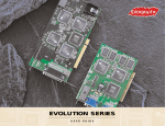
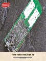
TWIN
TWIN ‘TUNA’/EVOLUTION
‘TUNA’/EVOLUTION 2V
2V
U S E R
G U I D E
laws, this manual and the software supplied with this product may not be copied, in whole or in part,
without written consent of Colorgraphic Communications Corporation, except in the normal use of
the software or to make a backup copy of the software. The same proprietary copyright notices
must be affixed to any permitted copies as were affixed to the original. Under the law, copy includes
translation into another language or format. You may use the software on any computer owned by
you, but extra copies cannot be made for this purpose.
This adapter has been tested and found to comply with the limits for a Class A digital device, pursuant
to Part 15 of the FCC Rules. These limits are designed to provide reasonable protection against harmful interference in a residential environment. This adapter generates, uses and can radiate radio frequency energy. Should this adapter not be installed and used in accordance with the instructions,
harmful interference to radio communications may occur. However, there is no guarantee that interference may not occur in a particular installation. If this adapter does cause interference to radio
reception, which can be determined by turning the equipment off and on, the user is encouraged to
try and correct the interference by one or more of the following measures:
•
Reorient or relocate the receiving antenna
•
Increase the distance between the equipment and the receiver
•
Connect the equipment into an outlet on a circuit different from that
which the receiver is installed
•
Consult an experienced radio technician for help, if necessary.
The following booklet prepared by the FCC may be helpful:
“How to Identify and Resolve Radio/TV Interference Problems”
This booklet is available from the U.S. Government Printing Office, Washington, DC 20402 Stock No.
004-000-00345-4.
TWIN ‘TUNA’/
‘TUNA’/
TWIN
EVOLUTION 2V
2V
EVOLUTION
To comply with the limits for the Class A device, pursuant to Part 15 of the FCC Rules, this card
must be installed in computer equipment certified to comply with the Class A limits. All cables used
U S E R
G U I D E
to connect the computer and peripherals must be shielded and grounded. Operation with non-certified computers or non-shielded cables may result in interference to radio or television reception. A
typical supplied monitor cable with a shielded interface cable with a ferrite core must be used in
F O R
P C I
L O C A L
C O M PAT I B L E
B U S
C O M P U T E R S
order to comply with the emission limit.
Colorgraphic Communications Corporation
5980 Peachtree Road • Atlanta, GA 30341-1602
Phone: 770-455-3921 Fax: 770-458-0616 Toll Free: 877-943-3843
Email: [email protected] • Support Email: [email protected]
www.colorgraphic.net
‘TWIN TUNA’/EVOLUTION 2V
International copyright laws protect this manual and software described within it. Under the copyright
TABLE OF CONTENTS
OVERVIEW
Overview ..........................................................................2
Hardware Installation ........................................................3
System Requirements ........................................................3
Installing the Video Adapter ................................................3
Video Adapter Diagram ......................................................4
Twin ‘Tuna’, part number 612180 ......................................5
Evolution 2V, part number 612181 ....................................6
Installing the A/V Cable for 4 Port ......................................7
A/V Cable Diagram ..........................................................8
TV Out/Jumper Configuration and Jumper Settings ..............9
Software Installation ......................................................10
Device Driver Installation for Windows 95 ..........................10
Device Driver Installation for Windows 98 ..........................11
Device Driver Installation for Windows NT 4.0 ....................12
Device Driver Installation for Windows 2000 ......................13
Installation Notes ............................................................14
MultiVu Software Installation ............................................15
Mover Software Installation ..............................................15
Product Specifications ....................................................16
Features ........................................................................16
Video Memory ................................................................16
Bus Architecture ............................................................16
Graphics Accelerator Functions ........................................16
Video Architecture ..........................................................17
Audio Architecture ..........................................................17
Graphics Modes..............................................................17
Technical Support ............................................................18
Troubleshooting ..........................................................19-22
Disclaimers ....................................................................23
Life Support ..................................................................23
Incidental Damage ..........................................................23
1
C
olorgraphic’s Twin ‘Tuna’* uses the latest in memory
and graphics accelerator technology along with unsurpassed video overlay capabilities. Independent cable
ready tuners for each video section allow viewing different TV channels on each screen. Using Colorgraphic’s
free drivers for Windows® 95/98, Windows NT and
Windows 2000, an image can be spread across multiple monitors to create one large virtual display. The
Twin ‘Tuna’ gives you high quality TV overlays with a high
performance multiscreen video adapter.
Colorgraphic’s Evolution 2V* uses our proven Evolution
Series video adapter coupled with the unsurpassed
video overlay capabilities of the Twin ‘Tuna’. With up to
four composite inputs and two S-Video inputs, the
Evolution 2V can meet a wide variety of video overlay
applications.
2
*Patent Pending
HARDWARE
INSTALLATION
System Requirements
Information presented in this section will help avoid potential
hardware and software conflicts.
Screw
The Twin ‘Tuna’/ Evolution 2V is a high performance multi-screen
video adapter. For the graphics card to function properly please
insure that your PC meets the following minimum requirements:
PCI Board
IBM PC compatible Intel Pentium PCI 2.1compliant system
Single PCI slot
2 or more VGA monitors: Multisync required for greater
than 640x480 resolution
16MB of system RAM (32 MB recommended)
1 MB minimum free hard disk space
Windows 95, Windows 98 or Windows NT 4.0
Installing the Video Adapter
(If necessary, refer to the computer user manual for instructions
regarding the removal of the computer cover)
Turn the computer off as well as all other peripheral devices
(printer, monitor, scanner, etc.) You may wish to disconnect all
cables from the PC, except the power cable. While this step is
not required it might make it easier to connect your audio and
video sources with the Twin ‘Tuna’/ Evolution 2V.
Remove the cover from your PC to expose the motherboard and
expansion slots. Remove the existing video adapter.
PCI Slot
Insert the Twin ‘Tuna’/ Evolution 2V adapter in any unused,
full-length PCI slot on the motherboard. Be sure to choose a
slot that allows adequate clearance of the CPU fans and case.
In some cases, installation may be facilitated by removal of the
mounting bracket at the end of the adapter. Colorgraphic does
not recommend the permanent removal of the bracket, as the
adapter could be damaged if the PC happens to be moved.
Note: Multiple cards may be placed in a system by repeating the adapter installation procedure.
3
4
Twin ‘Tuna’ • p/n 612180
Evolution 2V • p/n 612181
5
6
Installing the A/V Cable
A single 44 pin cable is included with the Twin ‘Tuna’ / Evolution
2V. It contains the connection points for your monitors, as well
as all audio/video inputs and outputs. This section details how
to attach the cable to your various devices. A diagram of the AV
cable can be found on page 9.
J11 J10 J9
J8
J7
J6
J5
J4 J3
J2
J1
Attach the 44 pin A/V cable to the card.
Connect the monitors to both 15-pin connectors. In the default
configuration, the LEFT monitor coincides with the connector
labeled “VGA Video 1” (J1). Attach the RIGHT monitor to the
connector labeled “VGA Video 2” (J2).
An audio source may be attached to the stereo mini phono plug
labeled “AUDIO Slave In” (J3).
The “AUDIO Master Out” (J5) may be directly connected to a set
of amplified speakers, or to a sound card with the included 6”
patch cable.
Two composite video sources may be connected to the RCA
phono plugs labeled “CVBS In 1” (J6) and “CVBS In 2” (J7).
Example: Composite Video Sources (CVBS) would include video
cameras, standard camcorders, VCR’s, etc.
Two S-Video sources may be connected to the mini DIN plugs
labeled “In 1” (J10) and “In 2” (J11). Example: S-Video sources
include DSS, DVD, Laser disk, etc.
Two composite video sources may be routed to external devices
by attaching cables to the RCA phono plugs labeled “CVBS Out
1” (J8), and “CVBS Out 2” (J9). Routable sources include TV
tuner (Twin Tuna only) and CVBS inputs. Example: This option
allows either the tuner or CVBS video to be displayed on an
external TV monitor, or routed to a VCR.
After all connections have been made, including any that were
disconnected prior to adapter installation, turn the computer on.
All boot up information should appear on Monitor 1, or the far
left display. It is possible that your PC may use the last monitor
as the boot screen. This is common in some PC’s. You will just
need to look at your last screen for boot up information.
Note: Multiple cards may be placed in a system by repeating the adapter installation procedure.
7
A/V Cable Diagram
8
TV Out/Jumper Configuration
NOTE: This section details the configuration and use of the TV
Out feature. Your adapter will have this capability if it was
ordered with the “-T” option.
With the TV Out option, a series of 3M mini-coax connectors
will be installed on the adapter. These connectors duplicate the
CVBS and S-Video inputs found on the external 44-pin A/V
cable. These internal connectors are labeled as follows
Label
J2
J3
J4
J5
J6
J7
J8
Connector
CVBS IN1
CVBS IN2
C/IN2
Y/IN2
C/IN1
Y/IN1
C/OUT2
J9
Y/OUT2
J10
J11
CVBS OUT2
C/OUT1
J12
Y/OUT1
J13
CVBS OUT1
Description
Composite Device Input
Composite Device Input
S-Video Chrominance Input
S-Video Luminance Input
S-Video Chrominance Input
S-Video Luminance Input
Chrominance Signal for
S-Video TV Output
Luminance Signal for
S-Video TV Output
Composite TV Output
Chrominance Signal for
S-Video TV Output
Luminance Signal for
S-Video TV Output
Composite TV Output
On A/V
Yes
Yes
Yes
Yes
Yes
Yes
No
No
Yes
No
No
Yes
Jumper Settings
JP 3 and JP 4 control the Input/Output selection for connectors CVBS OUT 1 & 2 on the 44 pin AV cable. The following
jumper configurations are detailed below:
Pins
1&2 =
2&3 =
2&4 =
Routed Video Output
Composite Video Input
Composite TV Out
Please contact Colorgraphic Technical Support for assistance
when altering the default configuration of these jumper settings.
9
SOFTWARE
INSTALLATION
Device Driver Installation for Windows 95
NOTE: Additional driver information will be in the
README95.TXT file, located in the W95\Evolution directory.
Windows 95 will autodetect the video card change. The
following steps will be required to load the video driver.
1. After the PCI Bridge Chip has been detected the New
Hardware Found window will appear. Select the option
Driver from product provided by hardware manafacturer
and click OK.
2. The Install From Disk window will appear. In the Copy manufacturer's files from: drop down window, type in the path
"X:\W95\Evolution" where "X" is the drive letter of the CDROM drive and click OK.
3. The System Settings Change window will appear, click No, so
the system will not restart. Depending on the number of
video ports in the system, this step will repeat until all ports
have been setup.
4. Click on Start->Shutdown and restart the system. After
reset, the monitor type will be detected. If the monitor is
plug-n-play, autodetection will occur.
The default setup will use all Twin ‘Tuna/Evolution 2V cards present in the system. To setup a specific monitor configuration,
click on Start->Settings->Control Panel. Double click the
SetArray icon. SetArray will allow you to specify the number of
horizontal and vertical displays that make up your configuration.
From SetArray you may also specify the vertical refresh rate.
5. The default multi-screen resolution will be 640x480x256
colors. Open the Display Properties window to adjust
the resolution/refresh rate.
10
Device Driver Installation for Windows 98
NOTE: Additional driver information will be in the
README98.TXT file, located in the W98\Evolution directory.
Windows 98 will autodetect the video card change. The
following steps will be required to load the video driver.
1. The PCI VGA Compatible Display Adapter is Detected window will appear and the Add New Hardware Wizard will open.
Click Next.
2. Select the option Display a list of all drivers in a specific location, so you can select the driver you want. Click Next.
Device Driver Installation for Windows NT 4.0
NOTE: Additional driver information will be in the README.TXT
file, located in the NT4\Evolution directory.
1. Make sure that NT 4.0 has been correctly installed on the host
PC, with a minimum of Service Pack 3.
2. From the Taskbar, choose START. From the START menu, select
Settings, then choose Control Panel.
3. Click the Have Disk... button.
3. Double-click the Display icon: this opens the Display Properties
window. Click the Settings Tab, and then select Display Type.
Click the Change button, under the Adapter Type section. This
opens the Change Display window. Click Have Disk button.
4. In the Copy manufacturers files from: drop down window, type
in the path "X:\W98\Evolution" where "X" is the drive letter of
the CD-ROM drive and click OK.
4. Type “X:\NT4\Evolution” in the text box, where “X” is the drive
letter for your the CD ROM drive. Click OK. Highlight the Evolution
graphics adapter from the Display list. Select OK.
5. The Add New Hardware Wizard window will appear, click Next
and the files will be copied.
5. A warning message will appear confirming your selection of a thirdparty driver. Click the Yes button.
6. After the files are copied, click Finish.
6. After the driver software has been copied to the system, click on
Start->Shutdown and restart the system.
7. The System Setting Change window will appear, click No, so
the system will not restart. Depending on the number of video
boards in the system, this step will repeat until all ports have
been setup.
8. Click on Start->Shutdown and restart the system. After reset,
the monitor type will be detected. If the monitor is plug-n-play,
autodetection will occur.
The default setup will use all Twin ‘Tuna’/Evolution 2V cards
present in the system with the resolution set to 640x480 256
colors. To setup a specific monitor configuration, click on
Start->Settings-> Control Panel. Double click the SetArray
icon. SetArray allows you to specify the number of horizontal/vertical displays in your configuration and to specify the vertical refresh rate.
The desktop resolution and color depth can be changed from
the Display Properties. To open the Display Properties, Click
on Start->Settings->Control Panel. Double click on the
Display icon.
11
After the system has been rebooted, the SetArray icon will be
added to your Control Panel. SetArray will allow you to specify
the number of horizontal and vertical displays that make up your
configuration. Example: Two monitors sitting side-by-side would
comprise a 2 (horizontal) X 1 (vertical) configuration.
Within SetArray, the Full Screen Display controls which screen
will be used when the DOS prompt is configured for a full screen
session.
The default multi-screen resolution will be 640x480x256 colors.
Return to the Display Properties window to adjust the resolution
and refresh rate.
12
Device Driver Installation for Windows 2000
NOTE: Additional driver information will be in the README.TXT
file, located in the W2000\Evolution directory.
Windows 2000 will autodetect the video card change. The
following steps will be required to load the video driver.
Installation Notes
After loading the virtual screen drivers under Windows you will
see multiple listings of the driver/hardware in device manager
and some have yellow exclamation marks. This is normal and
does not indicate a problem. (Windows 95/98 only)
1. After login the Found New Hardware window will appear stating
the Cirrus Logic 5480 is detected. Click Next to continue.
2. Click on "Display a list of the known drivers for this Device so
that I can choose a specific driver", click Next to continue.
3. Click on Specify a location and uncheck any drives than may be
checked. Click Next to continue.
4. Type in the directory or click Browse to point to the location
"X:\W2000\Evolution" where X is the location of the CD-ROM
drive. Click Ok to continue.
5. Click Next to continue to the Digital Signature Not Found window, click Yes to continue and the files will be copied. Click Finish.
6. The remaining devices of the Evolution 2V/Twin Tuna will be detected, click No so that a driver is not loaded for these as the first driver will operate all devices. Click Finish and repeat until all other
Evolution 2V/Twin Tuna devices have been prompted for.
7. Open the Device Manager by a right click on the My Compter
desktop icon. Select Properties and click on the Hardware Tab.
Click on the Device Manager button. Right click on each VGA
compatible device and select Disable. Click yes to continue and
repeat for all VGA devices
8. Exit the Device Manager and System Properties and restart the
system.
13
14
MultiVu Software Installation
MultiVu is a desktop video application that enables maximum
use of the Twin ‘Tuna’/Evolution 2V accelerator. A single tool
window controls channel selection, audio control, input selection and other video controls
To install the MultiVu Software, click the “Install MultiVu” button on the Software Installation program.
Mover Software Installation
Mover is a utility that facilitates window placement within a
multi-screen desktop. Features include dialog placement
tracked by the cursor position, application placement based
either on cursor position or user prompt for a specific screen.
To install the Mover Software, click the “Install Mover” button
on the Software Installation program.
PRODUCT
SPECIFICATIONS
Features
PC ’97 Compliant
Two independently programmable Cirrus Logic CL-D5480
accelerators
Two independently programmable cable ready tuners
(Twin ‘Tuna’ only)
Two composite NTSC/PAL and two S-Video external video
inputs
Master/Slave audio output for tuner audio
Slave audio input for external source or daisy-chain with
multiple cards
Independent (scalable to full screen) video overlay on each
screen
Hardware-based graphic operations
200 MHz video DAC for extended resolutions up to
1600x1200x64k, non-interlaced @ 70 Hz
VGA compatible
Increased Windows performance
High color and True color support
Video Memory
800 Mbytes/sec. Peak memory bandwidth
4 MEG SGRAM each section standard
Bus Architecture
32-bit PCI 2.1 compliant
Multiple boards can be installed in a single system
Twin Tuna uses a single full-length PCI slot
Evolution 2V is 6.5” in length
Graphics Accelerator Functions
64-bit high-bandwidth SGRAM interface
BitBlts
Font acceleration
Hardware cursor
Rectangle fills
15
16
TECHNICAL
SUPPORT
Video Architecture
16-bit YUV 422 digital video
TV tuner or external CVBS analog video routable to external monitor
or VCR/TV
External CVBS and S-Video Inputs routable to either video section
Color, brightness and contrast controls
Cable-ready TV tuner available in many formats: NTSC, PAL I, PAL B/G
(Twin ‘Tuna’ only)
Colorgraphic Communications Corporation supplies technical support free of charge to the end user or potential user. Contact
may be made via mail, voice, facsimile or the Internet.
Audio Architecture
Variable line level output, direct connect to PC sound card or amplifier
Bass and treble controls
Spatial/Pseudo stereo enhancement for TV audio
External input for multiple cards or other audio source
(DSS/VCR/LaserDisc)
Graphics Modes
All standard VGA compatible graphic modes as well as a
number of enhanced graphics modes are supported. The
following table list the enhanced graphic modes available
and their respective vertical refresh rates.
RESOLUTIONS
SUPPORTED
256 COLORS
REFRESH
RATES
Customer Service
Tech Support
Fax Support
Internet:
FTP
Sales
Voice
Tech Support
DOMESTIC
(770) 455-3921
(770) 455-3921
(770) 458-0616
www.colorgraphic.net
ftp.colorgraphic.net
[email protected]
1-877-WIDE-VIEW
1-877-943-3843
[email protected]
EUROPEAN
44 1202 747 044
44 1202 747 044
44 1202 747 114
www.colorgraphic.co.uk
[email protected]
[email protected]
European
Colorgraphic Communications Ltd.
Peachtree House
Acorn Business Park
Ling Road
Poole, Dorset BH12 4NZ
United Kingdom
1600x1200
1280x1024
1024x768
800x600
640x480
48/60/70 Hz
43/60/75/85/100 Hz
43/60/70/75/85/100 Hz
56/60/72/75/85/100 Hz
60/72/75/85/100 Hz
65535 COLORS
1600x1200
1280x1024
1024x768
800x600
640x480
48/60/70 Hz
43/60/75/85/100 Hz
43/60/70/75/85/100 Hz
56/60/72/75/85/100 Hz
60/72/75/85/100 Hz
Forefront Graphics Corporation
125 Ashwarren Road
Downsview, Ontario M3J 3K7
Canada
Tel (416) 636-4444
Fax (416) 636-4454
email: [email protected]
16.7M COLORS
1280x1024
1024x768
800x600
640x480
43/60/75 Hz
60/70/75/85/100 Hz
56/60/72/75/85/100 Hz
60/72/75/85/100 Hz
*Please refer to our web page for other distributors: www.colorgraphic.net
Canadian
Note: All standard VGA modes are supported.
17
18
TROUBLESHOOTING
Cause:
1
I have installed a Colorgraphic video card. When I
turn on my PC, I hear a series of beeps (typically,
one long beep and three short beeps) and it does
not boot. What does this mean?
Cause:
3
Text is displayed on my monitor, but my PC doesn't
appear to be booting.
Solution: The PC may be booting on a port that doesn't have a
monitor connected. Connect monitors to all ports.
Solution: The video card may not be fully inserted in the slot.
Power down the PC, remove the card and reinsert
it. Restart your PC.
Your PC may not support PCI bridge devices, check
with your PC manufacturer for a system BIOS
upgrade.
A jumper may be missing. Call technical support for
proper jumper configuration.
There may be another conflicting video adapter in
your PC. Remove the extra adapter and restart your PC.
If your PC has integrated video (on the motherboard),
disable the integrated video and restart your PC.
(Check your PC manuals for instructions on disabling
the integrated video.)
Cause:
4
After installing the Colorgraphic video drivers under
Windows NT, my PC still only comes up in singlescreen VGA mode. How do I get my PC to come up in
multi-screen mode?
Solution: In order to enable multi-screen support, Service Pack
3 or later must be installed.
Cause:
2
If PCAnywhere32 has been installed, make sure that
aw_host has been disabled in Control Panel / Devices.
There is no video on my monitor and my PC does
not boot.
Solution: It is possible that your PC may be using another video
adapter or integrated video (on the motherboard) as
the primary display device. Disable the integrated video
or remove the extra video adapter and restart your
PC. (Check your PC manuals for instructions on
disabling the integrated video.)
Cause:
5
I have installed my Colorgraphic adapter and drivers,
but all I see is a blue-green background. How do I get
the Windows desktop to appear?
Solution: Try connecting monitors to all ports. The default set
ting uses all available ports. You may not be able to
see the entire desktop with only one monitor connected.
19
20
Cause:
6
I have fewer than four monitors connected to my four
port card. It appears that part of my desktop is missing. How do I make the entire desktop appear?
Solution: You will need to modify the display configuration. The
default settings use all available ports in a horizontal
array. Open Control Panel, double-click SetArray and
modify the display array configuration. Set horizontal
displays to the number of monitors that you have connected. Set vertical displays to 1. Click the save
button to save your changes.
Cause:
7
I only have three monitors connected to my four port
card. How can I configure my PC to use only three
screens?
Cause:
9
I have loaded the Mover software, but still have a
single screen desktop.
Solution: A Colorgraphic multi-screen driver must be loaded in
order to enable multi-screen support. Mover is a window placement utility that does not enable multiscreen support. For information on driver installation,
please refer to the driver installation in this manual.
Cause:
10
My dialog windows are split across multiple monitors.
Is there a way to center them on a specific monitor?
Solution: Install the Mover software that is included with the
Colorgraphic driver diskette(s). Please refer to online
help for the Mover software configurations settings.
Solution: You will need to modify the display configuration. The
default settings use all available ports in a horizontal
array. Open Control Panel, double-click SetArray and
modify the display array configuration. Set horizontal
displays to the number of monitors that you have connected. Set vertical displays to 1. Click the save
button to save your changes.
Cause:
11
The logon display window is split between two monitors.
Is there a way to center the logon dialog box on a
single monitor?
Solution: No. The Mover software cannot control window
placement until after the logon is completed.
Cause:
8
After loading the Colorgraphic drivers under Windows
9x, I see multiple listings of the driver/hardware in
device manager and some have yellow exclamation
marks. Should there be multiple listings? Does the
exclamation mark indicate a problem?
Solution: A listing will appear for each accelerator chip. An
exclamation mark will appear next to all but the first
listing. This is normal and will not affect operation of
your PC.
21
Cause:
12
When attempting to load the Mover software,
I get a system beep (exclamation sound). What does
this mean?
Solution: Mover is already loaded. Look for the Mover icon in
the system tray near the clock.
If the PC is running in single screen mode or the
Colorgraphic driver is not loaded, Mover will not run.
22
DISCLAIMERS
Life Support
Colorgraphic Communications Corporation does not sanction,
authorize or certify any of its products for use in the design,
construction or use in or as critical care components of lifesupport systems or devices. Products of this nature are
defined as follows:
a) Life-support systems and/or devices are those that are
used to support/sustain life or are used to the same effect
when applied as a surgical implant and whose failure to
perform may result in serious injury or fatality.
b) Critical components are those which are integral and
essential to the design and construction of life-support
devices which are used to sustain/support life, and whose
failure to perform can be expected to significantly reduce
the effectiveness of said devices, which may result in serious
injury or fatality.
Incidental Damage
Colorgraphic Communications Corporation assumes no
liability or responsibility for damage to any device(s) of any
kind connected to the Twin ‘Tuna’/Evolution 2V adapters.
Damage to video display devices can sometimes occur if
the wrong resolution and refresh rate are chosen. It is the
responsibility of the user to know and understand the allowable
resolution and refresh rates for the video display device in use.
Always refer to the operations manual accompanying the video
display device prior to use.
1-877-WIDE-VIEW
1-877-943-3843
23
Colorgraphic Communications Corporation
5980 Peachtree Road • Atlanta, GA 30341-1602
Phone: 770-455-3921 Fax: 770-458-0616
Email: [email protected] • Support Email: [email protected]
www.colorgraphic.net