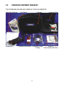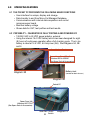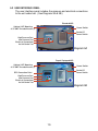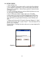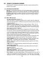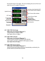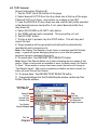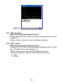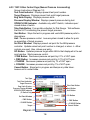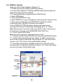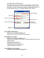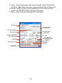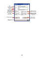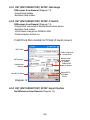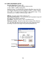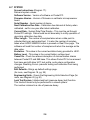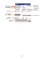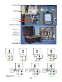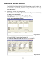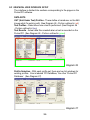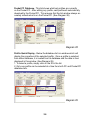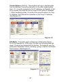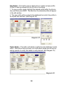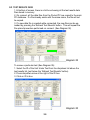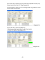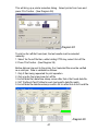
1
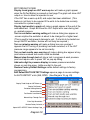
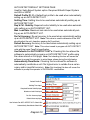
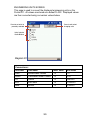
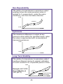
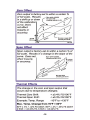
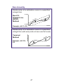
User Manual
Micro-Cal™
Model 869
Very Low Pressure Generating and Documenting Calibrator
Software Version V3.02
pressure transducers
800.257.3872 • Toll Free
978.264.0292 • Fax
setra.com • Web Site
2
Table of Contents
1.0 SAFETY INSTRUCTIONS........................................................ 5
2.0 INTRODUCTION ..................................................................... 6
3.0 STANDARD EQUIPMENT ....................................................... 7
4.0 OPERATING FEATURES
4.1 Pocket PC .................................................................... 8
4.2 Portability .................................................................... 8
5.0. CALIBRATOR SETUP
5.1 Battery Charging ......................................................... 9
5.2 Pocket PC Charging ................................................... 9
5.3 User Interface Panel ................................................. 10
5.4 Getting Started .......................................................... 11
6.0 POCKET INTERFACE SCREENS
6.1 Application Definitions ............................................. 12
6.2 Real Time: General .................................................... 12
6.21 Real Time: Dial Gauge .......................................... 13
6.22 Real Time: P-Switch............................................. 13
6.23 Real Time: Expert System .................................... 13
6.3 Test: General ............................................................. 14
6.31 Test: Dial Gauge ................................................... 15
6.32 Test: P-Switch ...................................................... 15
6.33 Test: Dither Control Page ..................................... 16
6.4 Profile: General ......................................................... 18
6.41 Profile: Dial Gauge ............................................... 19
6.42 Profile: Pressure Switch ...................................... 19
6.43 Profile: Expert System ........................................ 19
6.5 UUT SETUP: General .................................................. 20
6.51 UUT SETUP: Dial Gauge ........................................ 24
6.52 UUT SETUP: P-Switch ........................................... 24
6.53 UUT SETUP: Expert System .................................. 24
6.6 View a Reference Setup ............................................ 25
6.7 System ....................................................................... 26
7.0 UNIT UNDER TEST CONNECTION ........................................ 31
8.0 CALIBRATING/TESTING A TRANSDUCER/TRANSMITTER .. 31
3
9.0 MICRO-CAL MANAGER INTERFACE
9.1 Setup for Pocket PC Connection............................... 34
9.2 Graphical User Interface Setup ............................... 35
9.3 Test Results Data ...................................................... 39
10.0 GLOSSARY OF TERMS ...................................................... 42
11.0 SPECIFICATIONS ............................................................... 43
12.0 SPECIFICATION DERIVATIONS .......................................... 44
13.0 SPARE PARTS & ACCESSORIES ........................................ 48
14.0 WARRANTY & LIMITATION OF LIABILITY ......................... 49
4
1.0
SAFETY INSTRUCTIONS
Use the calibrator only as specified in the manual, otherwise the protection provided may be impaired.
Do not operate the calibrator in explosive gas, vapor or dust environments.
The calibrator is designed to operate from 14.4 VDC internal Lithium Ion
battery source or from the AC adaptor that is included. Do not use AC
adapters or chargers other than those supplied with the unit.
If supplying external excitation to the Unit Under Test in a measure mode,
do not exceed 30 VDC.
There are no user serviceable parts internally, removing the internal cover
will void warranty. Return the unit to the factory for re-certification or
repair.
BEST PRACTICES FOR CALIBRATOR OPERATION:
Use the shortest length of tubing from the calibrator to the Unit Under Test,
during pressure testing avoid vibration of the tubing.
Avoid movement of the calibrator during operation, avoid locating in a high
vibration environment.
Allow the calibrator to warm-up for one (1) hour before use. The calibrator
can be turned on during transport.
5
2.0
INTRODUCTION
DOCUMENTING PROCESS CALIBRATOR:
The Setra Micro-Cal Model 869 is a pressure generating, very low pressure documenting calibrator. The calibrator has been designed and
optimized to meet the needs of our customers for a capable system for
the calibration, troubleshooting and documentation of very low pressure
measuring sensors.
The design of the Model 869 exploits years of experience in the calibration of Setra transducers, as well as NASA patented and Setra exclusive
licensed technology. The Pocket PC user interface provides a familiar
“state-of-the-art” application of computer technology and an upgrade path
for future developments.
Major Features:
• Pocket PC user interface, capable of storing thousands of Units Under
Test (UUT) data files.
• Portable, battery powered system, capable of full operation for up to
eight (8) hours.
• Closed loop pressure control which is immune to the effects of ambient
pressure perturbations, (doors closing, people moving around).
• Very low internal reference pressure standards, which are selectable to
match customer needs.
• Auto zero pressure “tare” function.
• Ability to source power to the UUT, or use external power supply.
• Strip chart capability for troubleshooting drift conditions.
• High resolution pressure control capable of precise generation and
pressure control in the micro inch of water column pressure ranges.
• Leak testing
Expert-Equipped 869
Standard 869
Diagram 1
6
3.0
STANDARD EQUIPMENT BREAKOUT
THE ITEMS BELOW ARE INCLUDED IN YOUR CALIBRATOR:
Calibration Certificate
User Manual
Calibrator
Accessories Bag
AC Power Adapter
Diagram 2
Pocket PC
Pneumatic Fittings
Documentation and Cables
& Tubing
Electronic Test Lead Kit
7
4.0
OPERATING FEATURES
4.1 THE POCKET PC PERFORMS THE FOLLOWING MAJOR FUNCTIONS
• User interface for setups, display and storage.
• Data transfer to and from Micro-Cal Manager Database.
• Communications with internal data acquisition and control
microprocessor board.
• Monitors battery voltage
• Stores data for UUT, test profiles and test results.
4.2 PORTABILITY - CALIBRATOR IS FULLY PORTABLE AND POWERED BY
• 120/240 VAC to 24 VDC power adaptor, external
• Using the internal 14.4 VDC battery which has been designed for eight
(8) hours of continuous operation after a full charging cycle. The Li-Ion
battery is rated at 14.4 VDC, 6.6 Amp hour (AH). See Diagrams 3A, 3B
and 4.
User Interface Panel
Current Loop Fuse (63 mA)
Littlefuse #0218.063HXP
(See Spare Parts & Accessories)
Battery Jack
Diagram 3A
(Located on back of case.)
Diagram 3B
Pocket PC
Power Fuse (4A)
Littlefuse #H217004
(See Spare Parts & Accessories)
Serial Port On/Off
Switch
8
Diagram 4
5.0
CALIBRATOR SETUP
5.1 BATTERY CHARGING
The Calibrator is assembled, calibrated and tested at the factory. The
battery, as received, will be in a partially charged state. Before operation
please be sure to fully charge the battery to get maximum portable use of
the device.
TO CHARGE THE BATTERY:
• If calibrator is not in use for more than one month, Pocket PC
should be plugged into HP supplied power cable or be left
connected to AC power supply.
• Connect the AC power adaptor to AC supply connector on back of unit.
(shown in Diagram 3B)
• Battery charging will take approximately 6-8 hours.
5.2 POCKET PC CHARGING
TO CHARGE THE POCKET PC:
• Pocket PC will only charge from calibrator when the unit is on or A/C
adapter is plugged in.
• Pocket PC must remain charged.
• Drained to the point that the Pocket PC is at zero, the Pocket PC will
need to be plugged into a 5V adapter and charged to a minimum of 5%
before starting calibrator software . Battery charge can be checked
by going to: Start Menu > Settings > System > Power.
9
5.3 USER INTERFACE PANEL
The user interface panel includes the pressure and electrical connections
to the unit under test. (See Diagrams 5A & 5B.)
Standard 869
Optional UUT Mounting
8-32 UNF Threaded Inserts (2)
Power Switch
Pocket PC
Power Switch
High Pressure Port
Low Pressure Port
Electrical Connections
for Unit Under Test
Diagram 5A
Expert-Equipped 869
Optional UUT Mounting
8-32 UNF Threaded Inserts (2)
Power Switch
Pocket PC
Power Switch
EPIC Connection Point
High Pressure Port
Low Pressure Port
Electrical Connections
for Unit Under Test
Diagram 5B
10
5.4 GETTING STARTED
1. Open calibrator top.
2. Turn on calibrator power (power switch on right side of the calibrator).
3. Once calibrator is powered up, re-zero function begins automatically.
Please wait for completion. (User will hear operation of solenoid valves
and stepper motor).
4. Look for orange light (flashing or solid) on PDA (if light does not come
on, see section on battery charging).
5. Turn on PDA power (button in upper right corner of the PDA).
6. After powering up, tap the icon labeled Calibrator (tap START Menu
icon, tap on programs folder and tap on CALIBRATOR icon). Also, the
lower right button is programmed at the factory to start Calibrator software.
7. Software will startup with UUT selection Page (see Diagram 6). Select
desired UUT and press “OK” or press “Cancel”. Cancel will setup UUT as
±0.25 in. W.C. transmitter.
Keyboard Button - Pressing this button calls up an on-screen keyboard for
inputting data.
Keyboard
Button
Diagram 6
11
6.0
POCKET PC INTERFACE SCREENS
The Pocket PC Interface is tab-based, split into 6 major sections at the
bottom of the screen.
6.1 APPLICATION DEFINITIONS
General: This describes operation for the broadest range of applications.
Dial Gauge: Departures from general operation for Dial Gauge calibration.
P-Switch: Departures from general operation for Pressure Switch calibration.
Expert System: Departures from general operation for Expert System
calibration.
6.2 REAL TIME: General
Screen Instructions (Diagram 7):
Real Time page is constantly updating and is used to see the output and
pressure being applied for calibration purposes and test purposes (acts as
a digital indicator).
Applied Pressure Window: Displays system pressure. When “Go To
Pres.” is pushed, the text will turn yellow while pressure is outside of target control band. (Required control stability for UUT.) Text will turn green
when target pressure is reached.
Go to Pressure macro buttons are configured by UUT pressure range.
For all units, the top most button will display the UUT’s lowest Input Pressure. The bottom-most button will display the UUT’s highest input pressure. The middle button will display “0.0” for bidirectional units, and 50%
FS (Full Scale) of UUT range for unidirectional units.
Pressing any of the buttons enters the pressure value on the button into
the target pressure window and calls the “Go to Pressure” function.
HOLD SAMPLE: Will take a filtered reading and freeze the display with
that reading. To release, press the same button - Release Hold.
VENT: Opens both positive and negative pressure ports to each other
and atmosphere.
TARE: Zeros out internal pressure standard and re-zero’s mechanical
components in controller.
GO TO PRESSURE: Calls controller to generate pressure point set in
pressure target box.
HALT: Stops any process in action.
MONITOR/CONTROL: Switches calibrator into monitoring mode. This
allows calibrator to be used as pressure measurement device.
Error Graph is an auto-scaling display of the present error of the UUT’s
output as compared to the applied pressure. The red bars on the graph
represent the UUT’s accuracy specification limits. The labels will display
12
the present range of the graph. The arrow showing the error will turn red
when the error is outside of tolerance.
Excitation to Unit UnderTest (UUT)
Tares Internal Pressure Standard
Applied Pressure
Go To Pressure Macro buttons
UUT Output
Current Pressure Target
Monitor Mode
Snapshot of Any
Displayed Condition
Vents Pressure to Atmosphere
Halts Operation
Terminal Based
Error (%FS)
Includes Zero
and Span Errors
Bar Graph of
Error (%FS)
Diagram 7
6.21 REAL TIME: Dial Gauge
Differences from General (Diagram 7):
-Output and Error windows hidden.
-Bar Graph of Error is hidden.
6.22 REAL TIME: P-Switch
Differences from General (Diagram 7):
-Output window changes to OPEN/CLOSE indicator.
-Error window changes to OPEN/CLOSE capture window
-Bar Graph of Error is hidden.
6.23 REAL TIME: Expert System
Differences from General (Diagram 7):
-Monitor Only/Control button locked out, automatically controlled by the
process head connection/disconnection.
13
6.3 TEST: General
Screen Instructions (Diagram 8):
1. Tap the TEST tab at the bottom of the page
2. Select desired UUT ID from the drop down box at the top of the page.
If desired UUT is not there, see section on creating a new UUT.
3. View the PROFILE ID drop down box and confirm that profile selected
is the desired pressure test profile, if not, select desired profile from
drop down list.
4. Select AS FOUND or AS LEFT radio button.
5. Tap TARE and wait until completed. This zeroes the ref. unit.
6. Tap DO TEST button.
7. To stop a test in process, tap the STOP button. This will stop and
cancel the test.
8. Target pressure will be generated and data will be automatically
recorded at each pressure point.
Note: If the Display Test Results in Graph Option is selected (see Edit Defaults
page) - a graph will appear displaying pressure vs. error after the pressure
sequence has been completed (Diagram 9).
9. To record data - Tap RECORD TEST RESULTS button
Note: Record Test Results Button has 3 states indicating the save status of test
results. When no test results are available to save, the button reads “No Results
To Save.” When results on screen have been saved, the button will change to
“Test Results Saved.” After a test is complete and before the data is saved, the
button will read “Record Test Results.”
10. To review data - Tap REVIEW TEST RESULTS button
11. To expand/collapse the Test Profile/Results window, double tap Test
Profile / Results window.
Unit Under Test
(UUT) Identity
Profile ID
Do Test
Record Data
Review Data
Stop
Re-Zero
As Found/As Left
Test Selection
Target Pressure
Test Profile/
Results Window
Test Tab
Diagram 8
14
Diagram 9
6.31 TEST: Dial Gauge
Differences from General (Diagrams 8 & 9):
-Pressing DO TEST button brings up separate test page with dither control
(Diagram 10).
-Output columns removed from Test Profile/Results window.
6.32 TEST: P-Switch
Differences from General (Diagrams 8 & 9):
-Pressing DO TEST button brings up separate test page with dither control
(See 6.33 Dither Control Page, Diagram 10).
-Output columns removed from Test Profile/Results window.
-O/C column added to indicate the state of the pressure switch.
O - Open
C - Closed
15
6.33 TEST: Dither Control Page (Manual Pressure Incrementing)
Screen Instructions (Diagram 10):
Test Point Indicator: Displays present test point number.
Target Pressure: Displays present test point target pressure.
Eng Units Display: Displays pressure units.
Pressure Display Window: Displays present pressure during test.
OPEN/CLOSE Indicator: Available only with P-Switch, indicates open/
closed status of switch.
Take Data Button: Forces data collection for Dial Gauge. Tells software
that the UUT is indicating the present target pressure.
Vent Button: Stops the test in progress and vents 869 pressure ports to
atmosphere.
Halt: Pauses pressure control. Leaves system closed to allow for quick
re-acquisition of target pressure.
Set Point Window: Displays present set point for the 869 pressure
controller. Updates when test point number is changed, or when +/- dither
controls are used. Also, allows user entry.
GO Button: Updates pressure target within 869 to that displayed in the set
point window. Starts pressure control.
- FINE Button: Decreases pressure set point by 0.1% of UUT span.
+ FINE Button: Increases pressure set point by 0.1% of UUT span.
- COARSE: Decreases pressure set point by 1% of UUT span.
+ COARSE: Increases pressure set point by 1% of UUT span.
Cancel Button: Stops test in progress and dumps any data taken.
Leaves unit in vented state.
Test Type
Test Point Indicator
Target Pressure
Eng. Units Display
Pressure Display Window
OPEN/CLOSED Indicator
(P-Switch Only)
Take Data Button
Vent Button
Halt Button
GO Button
Set Point Window
- FINE Button
+ FINE Button
+ COARSE Button
Cancel Button
- COARSE Button
Target
Diagram 10
16
6.34 TEST: Expert System
Differences from General (Diagrams 8 & 9):
-Automatically starts test in “As Found” condition; records “As Found” data
-Automatically performs recal if “As Found” data is found to be outside
limits on UUT page
-Performs recal maximum of three tries before flagging UUT as “No Recal”
-Records successful recal “As Left”
-Test data available as “As Found” and “As Left” data pair
17
6.4 PROFILE: General
Setting up Test Profiles Database (Diagram 11):
1. Profiles are pressure settings used during testing.
2. Program has capability of creating additional test profiles besides the
default test profiles that are installed.
3. If a new profile setup is required tap the PROFILE tab.
4. Select NEW button
5. Type new PROFILE ID in box.
6. Select PROFILE to copy, (if desired) from drop down list, and press ‘OK’.
7. Once you’ve entered your new PROFILE ID, select the number
of data points box, highlight the number and change it.
8. Go to PROFILE TYPE drop down window, press down arrow
and select from the list of Ascending, Descending, Both, or Custom.
Note: When using both, the number of data points MUST be odd, it cannot be even.
9. If leak test is required, check PERFORM LEAK TEST box.
10. To save, press SAVE button.
Note: Save will be ‘grayed out’ when data has been saved.
11. To delete a profile, select PROFILE from list, and push DELETE button.
12. Custom test point profiles can be created. To adjust a custom test
point via the Custom Profile Editor Page (Diagram 12), tap the test point
number in the ‘TP #’ column of the profile display window.
13. Ascending, Descending, and Both will set up a profile with evenly
spaced points in the direction implied by the type. For custom point spacing, see the Custom Profile Editor Page.
Profile ID
Profile
Type
Perform
Leak Test
Target
Output
Number of
Test Points
Test
Point
%FS Target
Target
Pressure
Diagram 11
18
CUSTOM PROFILE EDITOR PAGE
This page allows entry of target pressure, target output, or target % FS
(Full Scale) to be stored for a test. To change, highlight value in any field,
and enter a new value. The remaining fields will update automatically. To
accept changes, press “OK”. To ignore changes, press “Cancel”.
Test Point Number
Target (%FS)
Target in Pressure Units
UUT Output Units
Exit Without
Saving Changes
Exit and Save Changes
Diagram 12
6.41 PROFILE: Dial Gauge
Differences from General (Diagram 11)
-Output column removed from test preview window.
6.42 PROFILE: P-Switch
Differences from General (Diagram 11)
-Output column changes to O/C column to indicate expected switch status
(OPEN/CLOSE).
-Profile selection locked out.
-Profile type selection locked out.
-Test point # entry window locked out.
-Leak Test selection locked out.
6.43 PROFILE: Expert System
No Differences from General (Diagram 11)
.
19
6.5 UUT (UNIT UNDER TEST) SETUP: General
Screen Instructions (Diagram 13):
UUT setup screeen is used for inputting UUT profiles into the UUT
database. The calibrator is supplied with many default instrument
templates which may be copied, modified and saved as new UUT.
1. Select an Existing Profile - Go to the UUT ID drop down
box, click the down arrow and select your unit from the list.
2. Create a New Profile - Tap NEW button at bottom of page, a dialog box
will appear prompting user to enter new UUT ID. Enter new ID in the
box and select UUT to copy if desired from drop down list below.
Press OK to create the new profile or CANCEL to cancel action.
Note: If you don’t want to copy an existing UUT you may select
DEFAULT from the drop down menu.
Note: To automatically setup a UUT using Setra’s configurable part
number, simply enter the Setra part number as the new ID, then press “OK”.
If the number entered is a valid configurable number, the UUT will be
automatically setup.
3. Enter the UUT’s Serial Number in the field provided.
4. In the Accuracy field, enter the pass/fail accuracy for the UUT.
5. In the ReCal Accuracy field, enter an accuracy (less than the one
entered in the Accuracy field) at which you would like the calibrator to
ReCal the transducer in spite of a passing result.
Note: Only used with Setra 269 and RPM. This feature is for automated
calibrations, is optional and can be useful for transducers that have drifted, but
are not yet failing, by avoiding a failing result at the next calibration.
6. Enter the transducer’s lowest and highest pressure in the LO and HI
boxes in the Input column.
7. Enter the transducers corresponding lowest and highest output in
the LO and HI boxes in the Output column.
8. Select DEFAULT TEST PROFILE (some default profiles are already
listed) select which one you want or create a new one (save UUT, go to
PROFILE page and create NEW, return to UUT and select newly
created profile for default profile and press SAVE).
9. Select Excitation Level from drop down list.
10. Select UUT Type from drop down list, Select one:
3 WIRE (VOLAGE)
4 WIRE (VOLTAGE)
CURRENT ( 4 - 20 mA)
PRESS SWITCH
DIAL GAGE
20
11. Save - Once all parameters have been changed, tap the SAVE button
at bottom. Note: Save button will be ‘grayed out’ when data has been saved.
12. Delete - Select UUT from list of available UUT ID’s at the top of the
screen. Tap DELETE button at bottom of the page.
13. More - Press to access remaining UUT setup items.
UUT ID Box
Profile Template ID
to Copy From
UUT Serial Number
UUT Input/Output
Specs (Ideal)
UUT Accuracy
Accuracy Spec Where
UUT Is Adjusted
UUT Type
Access the UUT
SUPPLEMENTAL PAGE
(Diagram 14)
Delete UUT ID
Save New
UUT ID
Excitation
New UUT ID Setup
Diagram 13
21
UUT SUPPLEMENTAL PAGE
1. Enter the UUT Part Number.
2. Enter the UUT Model.
3. Enter the UUT Manufacturer.
4. Enter the required pressure Settling Time at target (in milliseconds,
99,999 max. and 0 min, 5,000 recommended.) Pressure settling time
is time allowed at pressure point before data is acquired.
5. ENTER MAXIMUM LEAK RATE in box. This is PASS/FAIL criteria for
leak check function, measured in change of pressure per second.
6. Enter the required pressure stability for data acquisition in the Control
Stability field.
7. Enter the System Volume value (cu. in.). 64 is default. To increase
speed of pressure control, increase this value. The software
automatically programs this value based on testing performed at Setra.
It is recommended that the preprogrammed values always be used.
8. To accept the changes made, tap OK. To reject the changes made, tap
Cancel.
22
UUT
Part Number
UUT Model
UUT
Manufacturer
Setting Time
for Data Acq.
Max. Leak Rate
Allowable
for Pass/Fail
Adjust Pressure
Control Sensitivity
Pressure Stability
Required for Data
Acquisition
Accept Changes
Cancel and
Reject Changes
Diagram 14
23
6.51 UUT (UNIT UNDER TEST) SETUP: Dial Gauge
Differences from General (Diagram 13):
-Output fields hidden.
-Excitation field hidden.
6.52 UUT (UNIT UNDER TEST) SETUP: P-Switch
Differences from General (Diagram 13):
-Output fields converted to Manual Reset check boxes.
-Excitation field hidden.
-LO/HI labels changed to OPEN/CLOSE.
-Profile selection locked out.
P-SWITCH & DIAL GAUGE UUT PAGE (P-Switch shown):
UUT ID Box
Profile Template ID
to Copy From
Manual Reset
Check Boxes
(P-Switch)
OPEN/CLOSE
Input (P-Switch)
UUT Accuracy
Recalibration
Accuracy
Delete UUT ID
Save New
UUT ID
New UUT ID Setup
Diagram 15
6.53 UUT (UNIT UNDER TEST) SETUP: Expert System
No Differences from General (Diagram 13).
24
6.6 VIEW A REFERENCE SETUP
Screen Instructions (Diagram 16):
1. Tap the REF tab to view the different reference data.
2. Tap on REF 1 or REF 2 radio button.
Reference Setup - The Model 869 is shipped with either one or two internal reference transducers and are referred to as REF 1 or REF 2 respectively. REF 1 is the lowest range and REF 2 is the highest range. If only
one reference is installed, it will be located in REF 1.
REF ID - the serial number of the reference unit.
Input/Output Parameters - This section tells you the pressure range and
the output of the reference transducer.
Tare Button - Allows the user to “zero” the reference unit.
Reference Location - Shows the high and low ranges of the reference
unit, (the Model 869 automatically selects the proper reference sensor
according to the full scale range of the presently selected UUT).
Select Reference
Number
Select Reference
Tab
Diagram 16
25
6.7 SYSTEM
Screen Instructions (Diagram 17):
Data and system values:
Software Version - Version of software on Pocket PC.
Firmware Version - Version of firmware on calibrator microprocessor
board.
Serial Number - Serial number of device.
Next Calibration Due Date - Calibration due date set at factory when
calibrated - set for one year after latest calibration.
Current Date - System Date/Time Display - This must be set through
Pocket PC settings. Date should be set accurately to notify operators of
upcoming calibration due date.
Filter Length - The number of samples taken when a data point is
collected during an automated test. It is also the number of samples
taken when HOLD SAMPLE button is pressed on Real Time page. The
software will read this number of samples and return the average as the
data value.
Excitation - This value is the current excitation being provided to +EXC.
Battery Level - This value is the current battery voltage level.
Comm On - Check box allows interruption of communication stream
between Pocket PC and 869 base. This allows Pocket PC to be removed
from base and still allow UUT, test profile, and system configuration
changes. Disabling Comm. prevents testing and calibration from being
performed.
Edit Defaults - Brings up default settings page.
(for more, see Diagram 18, pg. 28)
Engineering Units - Opens the Engineering Units Selection Page (for
more, see Diagram 20, pg.30)
Leak Test System- Initiates leak test (pressure decay test) function.
This function should only be performed in a closed system.
The number returned is a rate of pressure decay.
26
Communication
On/Off Selector
Software Version
Firmware Version
Serial Number
Next Calibration
Due Date
Current Date
Filter Length
Default System
Setting
Eng. Units Setting
Leak Test System
Excitation
Battery Level
Diagram 17
27
EDIT DEFAULTS PAGE
Display trend graph on UUT warm-up box will make a graph appear
when the DoTest Button is pressed on test page.The graph will show UUT
output vs. time to allow the operator to see
if the UUT has a warm-up drift, and output has been stabilized. (This
feature is not likely to be required if the units to be tested are normally
connected to a power supply.)
Display test results in graph will make a graph appear at the end of the
automated test. Graph will show the UUT output error seen during test
vs. applied pressure.
Turn on excitation warning setting will make a dialog box appear on
screen anytime the excitation is about to be changed to a higher level.
(This is used to help prevent damage to unit. If all units to be tested can
accept 24VDC excitation, feature will not likely be required.)
Turn on miswire warning will make a dialog box pop up when it
appears the UUT wiring or plumbing has been reversed, or if the UUT
pressure range appears to be set incorrectly.
Turn on test results save warning will make a dialog box appear at any
point where unsaved test results could be deleted.
Manual step-through test will stop a test in progress at each pressure
point and require user to press ‘OK’ on pop-up dialog.
Add extra digit to pressure display increases pressure resolution
shown on real-time page. Adds one digit to the end.
Restore Factory Default Settings resets default settings to factory
programming.
Edit Default AUTO-DETECT Settings opens a page to access settings
for AUTO-DETECT units (269, RPM). (See Diagram 19, pg. 29)
Display Trend Graph on UUT Warm-up
Display Test Results
Excitation Setting Warning
Miswire Warning
Test Results Save Warning
Manual Step-Through Test
Extra Digit Resolution
Restore Factory Defaults
Opens AUTO-DETECT Default Settings Page
Diagram 18
28
AUTO-DETECT DEFAULT SETTINGS PAGE
Used for Setra Expert System option. Requires 869 with Expert System
and 269 or SRPM.
Default Profile ID: ID of default test profile to be used when automatically
setting up an AUTO-DETECT UUT.
Settling Time: Settling time to be used when automatically setting up an
AUTO-DETECT UUT.
Req’d Ctrl. Stability: Required control stability to be used when automatically setting up an AUTO-DETECT UUT.
Max. Leak Rate: Maximum leak rate to be used when automatically setting up an AUTO-DETECT UUT.
Re-Cal Accuracy: Re-cal accuracy to be used when automatically setting
up an AUTO-DETECT UUT. Note: This value is used to determine if the 869
should adjust the unit, despite a passing As Found test.
Default Accuracy: Accuracy to be used when automatically setting up an
AUTO-DETECT UUT. Note: This value is used to program all AUTO-DETECT
units with the same Pass/Fail specification.
Use Defaults For AUTO-DETECT UUT’s: Checking this box allows the
software to automatically program an AUTO-DETECT UUT profile using
the values stored on this page. Note: Not checking this box will cause the
software to prompt the operator to enter these values during the initial setup.
Automatically Recalibrate: Checking this box allows the software to
automatically recalibrate a unit if its highest error is outside the re-cal accuracy and/or pass/fail accuracy. Note: Not checking this box will cause the
software to prompt the operator to OK/CANCEL recalibration.
Default Profile ID
Settling Time Input
Required Control Stability Input
Maximum Leak Rate Input
Re-Cal. Accuracy Input
Default Accuracy Input
Use Defauts For AUTO-DETECT UUT’s Check Box
Automatically Recalibrate Check Box
Diagram 19
29
ENGINEERING UNITS SCREEN
This page is used to convert the displayed engineering units on the
Pocket PC. All values are stored as a default in WC. Displayed values
are then converted using conversion values below.
Press to exit w/out
changing units
Press to set units to
presently selected
Units Selector
Radio Buttons
Diagram 20
Conversions:
Unit Abbr.
Unit Name
inWC Value
Unit Value
inWC
Inches Water Column
1.0
1.0
cmWC
Centimeters Water Column
1.0
2.54
Pa
Pascal
1.0
248.6491
kPa
KiloPascal
1.0
0.2486491
mbar
Millibar
1.0
2.486491
30
7.0 UNIT UNDER TEST CONNECTION
STANDARD 869 - (See Diagram 22)
1. Attach the unit in a secure location. Two 8-32 threaded inserts are provided in the area above the USER INTERFACE PANEL to install the UUT.
A custom bracket may be created to mount to these inserts for testing the
UUT in a desired location.
2. Hook up the pneumatic lines - attaching the high port (HI) on the calibrator to the high port on the UUT and the low port (LO) on the calibrator
to the low port on the UUT.
3. Hook up electrical - (See Diagram 23, pg. 32)
EXPERT SYSTEM - (See Page 33)
8.0
CALIBRATING/TESTING A TRANSDUCER/TRANSMITTER
MANUAL CALIBRATION:
1. Select UUT tab. Select UUT ID from list and verify.
2. Select REAL TIME tab
3. Connect UUT according to UUT Connection Guide (Above).
4. Press the -FS button (will be updated in the target pressure window) it
will generate the lowest pressure of the UUT range, wait until pressure is
achieved.
5. At this point, you may adjust the zero adjustment on the UUT until the
output is within desired tolerance.
6. Once zero is adjusted, press the +FS button (target pressure will again
update in window) wait until pressure is achieved. You may adjust the
span potentiometer until within desired specification.
7. Unit should be calibrated at this point. To verify, select TEST tab.
AUTOMATED TEST:
1. Select TEST tab
2. Select UUT from list, (if not available, follow instructions for creating
new).
3. If selected test profile is not desired test, then select NEW test from list.
4. Press DO TEST button and wait for completion.
EXPERT SYSTEM TEST:
(see page 33)
31
Standard 869
Unit Under Test
(Model 260)
Electrical Lines
Pneumatic Lines
869 Expert System
EPIC Cable Plug
(UUT End)
Unit Under Test
(Model 269)
EPIC Cable Plug
(Calibrator End)
EPIC Cable
Diagram 22
_
+
EXC
24VDC
EXC
EXC COM +SIG -SIG
SIG
COM
COM
EXC
24VDC
COM
EXC
24VDC
COM
SIG
(-)
SIG
(+)
SIG
(-)
SIG
(+)
SIG
(-)
SIG
(+)
Current Internal
Excitation
P-Switch SPST
External
Power
Supply
+
_
Diagram 23
+
SIG
(+)
+
_
EXC
COM
SIG
External
Power
Supply
EXC
24VDC
COM
EXC
24VDC
COM
SIG
(+)
SIG
(-)
SIG
(+)
SIG
(-)
3-Wire External
Excitation
Current External
Excitation
32
COM
SIG
(-)
4-Wire Internal
Excitation
3-Wire Internal
Excitation
_
External
Power
Supply
EXC
24VDC
+
_
EXC COM +SIG -SIG
EXC
24VDC
SIG
(+)
COM
SIG
(-)
4-Wire External
Excitation
EXPERT SYSTEM TEST:
1. Select UUT Test Tab.
2. Select “Auto-Detect” from UUT ID dropdown box. Wait for software
prompt to plug EPIC cable into Transducer.
3. Remove Process Head from pressure sensor and plug in EPIC
connector. Epic must also be connected to 869 top panel header.
FIRST TIME UUT AUTO-DETECT - The 869 will automatically download and save a new UUT Profile from a Setra 269 or SRPM.
A) UUT ID Selection Screen will appear.
B) Enter tag number or UUT ID number.
C) Tap OK.
D) UUT Part Number Screen will appear. Complete part # and tap
OK.
E) All setup data for UUT will be automatically downloaded and stored
under new UUT ID Number.
F) Ready to initiate test.
4. Select Test Tab.
5. Press ‘Do Test’ and wait for completion.
A) If “As Found” data is within the user-selected Re-Cal AccuracyThe 869 saves the test data as both “As Found” and “As Left” and the
calibration/testing is complete.
B) If “As Found” data is outside the user-selected Re-Cal Accuracy The 869 initiates automatic zero and span adjustments (Auto Re-Cal).
The 869 will perform the re-cal process up to three times to meet the
designated Re-Cal Accuracy. One correction is usually sufficient to
re-cal a UUT; however, if re-cal is not achieved, then the 869 displays
the following message:
“UNABLE TO ADJUST UNIT TO SPECIFIED RE-CAL ACCURACY”
C) Any Re-Cal process will result in test data being saved in ‘As
Found’ and ‘As Left’ data files.”
6. Remove EPIC Connector from UUT and replace UUT Process Head.
UUT is returned to service operation.
33
9.0 MICRO-CAL MANAGER INTERFACE
The MICRO-CAL MANAGER INTERFACE provides a central location for
all data within a given facility, database management and easy data entry
and manipulation.
9.1 SETUP FOR POCKET PC CONNECTION
1. Install Microsoft ActiveSync (Please follow ActiveSync setup instructions).
2. Select GUEST partnership.
3. Verify device is connected on Microsoft ActiveSync.
CONNECTED should now appear in ActiveSync window.
4. Run Micro-Cal Manager software.
Diagram 24
5. Press CONNECT button (See Diagram 25)
6. Screen will update with data from both PC and Pocket PC.
Diagram 25
34
9.2 GRAPHICAL USER INTERFACE SETUP
The interface is divided into sections corresponding to the pages on the
Pocket PC software.
DATA SETS
UUT (Unit Under Test) Profiles - These define a transducer so the 869
knows what it’s working with. (See Diagram 26 - Portion outlined in red)
Test Profiles - Determines how a test is performed. (See Diagram 26
- Portion outlined in blue)
Test Results - Actual data files created when a test is recorded on the
Pocket PC. (See Diagram 26 - Portion outlined in green)
Diagram 26
Profile Selection - With each profile set, there are two list windows for
existing profiles. One is labeled ‘PC DataBase,’ the other ‘Pocket PC
Database.’ (See Diagram 27)
Diagram 27
35
Pocket PC Database - This list shows what test profiles are currently
on the Pocket PC. After editing any profile, said profile will automatically
download to the Pocket PC. This ensures that the list window always accurately reflects what is on the Pocket PC. (See Diagram 28)
Diagram 28
Profile Quick Display - Below the database list is a window which will
display the properties of the selected profile. Once a profile is selected,
from either database, it is loaded from its database and the data is then
displayed in this window. (See Diagram 29)
1. To select a profile, simply click on the ID in the list.
2. Only one profile can be selected at a time from both PC and Pocket PC
database lists.
Diagram 29
36
Transfer Buttons (‡ & fl) - These buttons will copy a selected profile
from the database it currently exists within, to the other remaining database. I.E., if a profile is selected in the PC database, and Transfer ‡ button is pressed, the profile will now be copied to the Pocket PC database.
1. When transfering profiles, if a profile of the same ID exists in the ‘Copy
To’ database, the profile will be overwritten on the ‘Copy To’ database.
(See Diagram 30)
Diagram 30
Edit Button - This button opens a dialog box containing the information for the selected file. At this point, the data may be manipulated and
saved. ID cannot be changed with this function. To change ID, copy the
profile (See ‘New Button’ section, following), giving it a new ID, then delete
the old version. (See Diagram 31)
Diagram 31
37
New Button - This button opens a dialog box to create a unique profile.
Profile ID must be entered into the ID box on the dialog.
1. To copy a profile, simply highlight the desired profile within the list window, and then press NEW. The data from the selected profile will appear
in the edit window.
2. The new profile will be copied to the database from which the profile to
be copied was selected. (See Diagram 32)
Diagram 32
Delete Button - This button will delete a profile from the database it exists
within. Data cannot be recovered, so a verification dialog box will pop up
asking operator to verify that delete is really desired. (See Diagram 33)
Diagram 33
38
9.3 TEST RESULTS DATA
1. At bottom of screen, there is a list box showing all the test results data
files stored in memory.
2. On connect, all the data files from the Pocket PC are copied to the main
PC database. If a file already exists with the same name, the file will not
be copied.
3. If a new data file is created while connected, the new files can be uploaded by pressing the ‘Refresh Test Results’ button. This will repeat the
file upload procedure performed on connect. (See Diagram 34)
Diagram 34
Screen Shot with tests listed.
To review a particular test (See Diagram 35):
1. Select the ID of the Unit Under Test from the dropdown list above the
test results list (just below the ‘Refresh Test Results’ button).
2. Press dropdown arrow at the right of the ID box.
3. Click on ID in box.
Diagram 35
39
Once a UUT ID is selected, the test results list will update to display only
the test results from that UUT. (See Diagram 36)
The test results for each UUT can be distinguished using date/time of test
and As Left/As Found status.
Diagram 36
Screen Shot with tests listed.
To print ‘As Left’ or ‘As Found’ data only:
1. Select any profile desired from the list of test results.
2. Press ‘Print’ button. (See Diagram 37)
Diagram 37
Screen Shot with tests listed.
40
This will bring up a printer selection dialog. Select printer from here and
press ‘Print’ button. (See Diagram 38)
Diagram 38
To print an As Left/As Found pair, the test results must be selected
manually:
1. Select ‘As Found’ file then, while holding CTRL key, select ‘As Left’ file.
2. Press ‘Print’ button. (See Diagram 39)
Before data can be sent to the printer, the 2 selected files must be verified
as a valid pair. Data is validated as follows:
1. Only 2 files being requested for print operation.
2. Only one As Found and one As Left file.
3. As Left data file’s date/time stamp comes after that of As Found data file.
4. UUT Profiles & Test Profiles for each test result’s data file match.
5. As Left data file date/time stamp is within 24 hrs after that of As Found file.
Diagram 39
Screen Shot with tests listed.
41
10.0 GLOSSARY OF TERMS
Atmospheric Pressure - Pressure of the atmosphere at the Earth’s
surface. NIST standard atmospheric pressure = 1.01325 bar.
Burst Pressure - The mazimum pressure that may be applied to the positive pressure port without rupturing the sensing element.
Capacitive Sensing - Detection and measurement of pressure through
the change in voltage accross a capacitor, one plate of which is a diaphragm which deflects slightly with changes in applied pressure.
Differential Pressure - Pressure measurement relative to a reference
pressure. Referred to as pounds per square inch differential (PSID) or
inches of water column differential (WCD).
FS (Full Span or Full Scale) - The range of measured values over which
a transducer is intended to measure, specified by the upper and lower
limits. Ex: 0 to 100 PSIG, FS is 100 PSIG/0 to 5 VDC, 800-1100 MB, FS
is 300 MB.
P/I - Term common to process industries meaning pressure-in/current-out.
Ex: 3-15 PSIG Input to 4-20 mA DC Output.
Pressure Transducer - An electromechanical device for translating fluid
pressure values into voltages across a high-impedence (5k ohms or
greater) load.
Pressure Transmitter - An electromechanical device for translating fluid
pressure values into currents (generally 4-20 mA) into a low-impedence
load.
Proof Pressure - The maximum pressure that may be applied without
changing performance beyond specifications (typically 0.5% FS zero
shift).
Range - The spread between the maximum and minimum pressures
between which the transducer has been designed to operate.
Span - The algebraic difference between the limits of the range. Ex: 0.1
to 5.1 Volts DC, span is 5VDC. Sometimes used to designate full scale
output; i.e. 5 VDC.
42
11.0 SPECIFICATIONS
11.1 MEASUREMENT
Accuracy........................................................ ........................... ±0.04% FS
Precision................................................................................. 0.0002” W.C.
Calibration Stability (Span)........................................................ 0.2% FS/yr
Calibration Adjustment.................................................................. zero tare
Resolution................................................................................. up to 1 ppm
Compensated Temperature Range ....................................... 40oF to 120oF
Storage Temperature Range.................................................. 40oF to 160oF
Temperature Effect (Zero).................................................... none, zero tare
Temperature Effect (Span)............................................................ 0.01%/oF
Certification............ ......................NIST traceable certification for reference
pressure sensors and voltage/current meters.
11.2 CONTROL
Controlled Pressure Stability....................................... 0.0002” W.C., typical
Minimum Controlled Pressure .............................................. 0.00005” W.C.
Dual Reference Pressure Ranges........................................ see order info.
Pressure Types.......................................................... gauge and differential
Overpressure Limit............................................................................. 5 psid
Control Time ....................................................................... user selectable
11.3 GENERAL SPECIFICATIONS
Pressure Units (Selectable).....................in. W.C., Pa, kPa, mbar, cm W.C.
Warmup...................................................................................... 30 minutes
Reading Rate....................................................20 readings/second, typical
Gravity/Orientation........................................................................ negligible
Shock and Vibration................................................................5g, maximum
Communications.............................................................................. RS 232
Display......................... 3.5” transflective type TFT color, QVGA, 64-k color
Keypad................. pocket PC touch pad and external ASCII keyboard plug
Size......................................... 11” x 14” x 6” (27.9 cm x 35.6cm x 15.2 cm)
Weight................................................................................... 16 lbs. (7.3kg)
Pressure Media.......................................... clean, dry. non-corrosive gases
Power................... 120/240 AC, 50/60Hz, LITHIUM-ION battery - 8 hours
operation
Pressure Transducer Interface Pressure Fittings............................... barbed, plug-in o-ring quick connects
Electrical ..................................................................... banana plug jacks
Voltage Meter ............................................... ±0.005% FSO at ±10 VDC
Current Meter .................................................. ±0.005% FSO at 4-20mA
Excitation ..... .............24 VDC nominal for 4-20 mA output, 5 to 24 VDC
for voltage output
43
12.0 SPECIFICATION DERIVATIONS
Total Error Band
(Worst case) over a temperature range of
-10°F to +130°F
Non Linearity:
±0.1% FS
Hysteresis:
±0.05% FS
Non-Repeatability:
±0.02% FS
Thermal Zero Shift:
< ±0.32% FS
Thermal Span Shift:
< ±0.24% FS
Zero Offset:
±0.2% FS
Span Offset:
±0.2% FS
±1.13% FS
Long-term stability error not included.
44
Non-Repeatability
The ability of a transducer to reproduce output
readings when the same pressure value is
applied to it consecutively, under the same
conditions, and from the same direction.
5 VDC
<0.02%FS
0 VDC
0 PSI
100 PSI
Hysteresis
The maximum difference in output at any
pressure value within the specified range, when
the value is approached with increasing and
decreasing pressure.
5 VDC
<0.05%FS
0 VDC
0 PSI
100 PSI
Long-Term Stability
The ability of a transducer to reproduce output
readings obtained during its original calibration
at room conditions for a specified period of time.
5 VDC
Example: ±0.1% FS
Over 6 Months at
70°F (21°C)
+0.
1%
FS
1
-0.
%F
S
Original Calibration
After 6 Months
0 VDC
0 PSI
45
100 PSI
46
Non-Linearity
Relationship of a calibration curve to a specified
straight line.
Best Fit
Straight Line
(BFSL)
Method
5.1 VDC
1
+0.
S
%F
-0.1
S
%F
0.1 VDC
Example: ±0.1% FS
0 PSI
100 PSI
Terminal
Method
Example: ±0.12%
FS
RS232 OUTPUT
Relationship of a calibration curve to a specified
straight line with end points at zero and full scale.
0
-0.
.0
+0
0 PSI
12
12
%
%F
100 PSI
47
13.0 SPARE PARTS & ACCESSORIES
Part #
269701
269425-02
869902
869904-xx
869905-xx
869909
869910
869912-xx
869913
869914
869920
869921
869901
869922
869923
869924
406731
869714
869969-06
869969-12
Item
269 terminal block
security key
accessory bag
electro-pnuematic harness; 2 wire
electro-pnuematic harness; 4 wire
terminal, fork, 18AWG; #6
mini-alligator clip
shrouded banana plug
Pocket PC, USB cradle
Pocket PC; power adapter, universal
harness cable end assy, 2 wire
harness cable end assy, 4 wire
Pocket PC screen protector
pre-programmed Pocket PC
acessory kit
stylus, 3 pack
Littlefuse # 0218.063HXP = 5 x 20 mm; 0.63 ma;
time lag; 250vAC rating
Littlefuse # H217004
= 5 x 20 mm; 4 A ; fast
acting; 250vAC rating
EPIC Cable - 6 feet
EPIC Cable - 12 feet
48
14.0 WARRANTY & LIMITATION OF LIABILITY
SETRA warrants its products to be free from defects in materials and
workmanship, subject to the following terms and conditions: Without
charge, SETRA will repair or replace products found to be defective in
materials or workmanship within the warranty period; provided that:
a) The product has not been subjected to abuse, neglect,
accident, incorrect wiring not our own, improper installation or
servicing, or use in violation of instructions furnished by
SETRA;
b) the product has not been repaired or altered by anyone except
SETRA or its authorized service agencies:
c) the serial number or date code has not been removed,
defaced, or otherwise changed; and
d) examination discloses, in the judgement of SETRA, the defect
in materials or workmanship developed under normal
installation, use and service.
e) SETRA is notified in advance of and the product is returned to
SETRA transportation prepaid.
Unless otherwise specified in a manual or warranty card, or agreed to in
writing and signed by a SETRA officer, SETRA pressure and acceleration products shall be warranted for one year from date of sale.
The foregoing warranty is in lieu of all warranties, express, implied or
statutory, including but not limited to, any implied warranty of merchantability for a particular purpose.
SETRA’s Liability for breach of warranty is limited to repair or replacement, or if the goods cannot be repaired or replaced , to a refund of the
purchase price. In no instance shall SETRA be liable for incidental or
consequential damages arising from a breach of warranty, or from the
use or installation of its products.
No representative or person is authorized to give any warranty other
than as set out above or to assume SETRA any other liability in connection with the sale of its products.
49
50
SS869 0 4/24/09 Rev C
Setra Systems, Inc., 159 Swanson Rd, Boxborough, MA, 01719
To modify a UUT ID, select desired UUT ID from dropdown screen, make changes, and tap “save”. The newly created or modified UUT IDs
will be available from dropdown UUT ID screen.
To create a new UUT ID go to the UUT screen and tap “new” button. Next, type in a new UUT ID in the upper box. Enter data by tapping
the keyboard icon in lower right of screen. Characters are entered on screen at the cursor when mini-keyboard characters are tapped. An
existing ID template must be selected in “copy from” box. It is suggested that an existing ID template be chosen that closely matches the
pressure sensor desired to test either in pressure range or output type. Tap “ok”. When screen returns to UUT, any ID values can be modified using keypad. Use dropdown boxes to change excitation, output type, or number of test points. Hit “save” button and new test profile is
ready to use.
Creating and Modifying UUT ID’s
Go to “Test” screen and tap “Do Test” button to initiate automatic calibration test. The calibrator will apply test pressures and record output
results until “test complete” flag is displayed. You can save the test data by tapping the “Save Test Results” button. The data is saved with
fittings. Hook up connections as follows:
1. 4-20mA current loop operation, connect +EXC to red 869 banana jack and -EXC to black jack.
2. For 3-wire voltage output operation, connect +EXC to red electrical jack, -EXC common to black jack, and +Output to green
VI jack.
Return to “Real Time” screen to verify correct zero pressure output of test pressure sensor. Tap “tare” button to re-zero onboard pressure
references (approx 10 seconds). You can also check full-scale output by tapping “+FS” (+ full scale) button. You can also make zero and
VII span adjustments to test pressure sensor at this time.
V Plug in pressure tubing and electrical cables into marked sockets on the top panel. Connect pressure tubing to “high” and “low” pressure
you wish to test - (tap the down arrow in the top box to view all of the stored UUT test profiles). Power is supplied to test pressure sensor
when UUT ID is selected. If a needed ID is not found, see Creating and Modifying UUT ID’s below.
IV Calibrator starts in “Real Time” mode. Tap UUT (Unit Under Test) tab and select a stored UUT ID that corresponds to the pressure sensor
programs run” or “programs” file from drop down menu.
I Apply power to calibrator with AC adapter or charge battery.
II Turn on power switch located in the top right corner. Power is on when green light illuminates - the pocket PC will flash an orange light.
III Push Pocket PC power button in top right of the unit. It will display a “start” screen. Tap “start” and select Setra Calibrator icon from “last
Micro-Cal® Model 869 Quick Start Guide