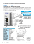
1
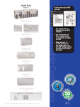
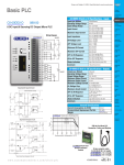
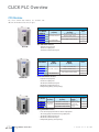
CLICK PLC Overview
CPU Modules
The eleven CLICK CPU modules are available with
different combinations of built-in I/O types.
CLICK Basic CPU Modules
Part Number
C0-00DD1-D
C0-00DD2-D
C0-00DR-D
C0-00AR-D
Basic CPU
Inputs
(8 points)
Outputs
(6 points)
Price
DC (0.1 A, 5-24 VDC, Sink)
<--->
DC (24 VDC, sink/source)
DC (0.1 A, 24 VDC, Source)
<--->
Relay (1 A@6-27 VDC/6-240 VAC)
AC (100-120 VAC)
<--->
<--->
Basic CPU Module Features:
• Eight discrete input points
• Six discrete output points
• Two RS-232 communications ports
CLICK Standard CPU Modules
Part Number
C0-01DD1-D
C0-01DD2-D
C0-01DR-D
C0-01AR-D
Standard CPU
Inputs
(8 points)
DC (24 VDC, sink/source)
AC (100-120 VAC)
Outputs
(6 points)
Price
DC (0.1 A, 5-24 VDC, Sink)
<--->
DC (0.1 A, 24 VDC, Source)
<--->
Relay (1 A@6-27 VDC/6-240 VAC)
<--->
<--->
Standard CPU Module Features:
• Eight discrete input points
• Six discrete output points
• Two RS-232 communications ports
• One RS-485 communications port
• Backup battery (Battery sold separately)
CLICK Analog CPU Modules
Part Number
C0-02DD1-D
C0-02DD2-D
C0-02DR-D
Analog CPU
Inputs
(4 points)
Outputs
(4 points)
Analog Inputs,
Outputs
2 channels in / 2
channels out; voltage
(0-5 VDC) and
DC (0.1 A, 24 VDC, Source)
current (4-20 mA)
Relay (1 A@6-27 VDC/6-240 VAC) selectable
DC (0.1 A, 5-24 VDC, Sink)
DC (24 VDC,
sink/source)
Price
<--->
<--->
<--->
Analog CPU Module Features:
• Four discrete input points and four discrete output points
• Two analog input points and two analog output points
• Two RS-232 communications ports
• One RS-485 communications port
• Backup battery (Battery sold separately)
Volume 13
e1-16
Programmable Controllers
1 - 80 0 - 633 - 0405
CLICK PLC Overview
Company
Information
Systems
Overview
Input I/O Modules
Programmable
Controllers
There are six input I/O modules available.
Field I/O
CLICK Input I/O Modules
C0-08ND3
C0-16ND3
C0-08ND3-1
Part Number
C0-08ND3
C0-08ND3-1
C0-16ND3
C0-08NE3
C0-16NE3
C0-08NA
Inputs
Price
DC (8 pts, 12-27 VDC)
<--->
DC (8 pts, 3.3-5 VDC)
<--->
DC (16 pts, 24 VDC)
<--->
AC/DC (8 pts, 24 VAC/VDC)
<--->
AC/DC (16 pts, 24 VAC/VDC)
<--->
AC (8 pts, 100-120 VAC)
<--->
Software
C-more &
other HMI
Drives
Soft
Starters
Motors &
Gearbox
Steppers/
Servos
Motor
Controls
Proximity
Sensors
C0-08NE3
Photo
Sensors
C0-08NA
C0-16NE3
Limit
Switches
Output I/O Modules
C0-08TD1
C0-16TD1
C0-08TD2
Encoders
CLICK Output I/O Modules
There are seven output I/O modules available.
Part Number
Outputs
DC (8 pts, 0.3 A @ 3.3-27 VDC, Sink)
C0-08TD1
DC (8 pts, 0.3 A @ 12-24 VDC, Source)
C0-08TD2
DC (16 pts, 0.1 A @ 5-27 VDC, Sink)
C0-16TD1
DC (16 pts, 0.1 A @ 12-24 VDC, Source)
C0-16TD2
AC (8 pts, 0.3A @ 17-240 VAC)
C0-08TA
Relay (4 pts, 7A @ 6-27 VDC/6-240 VAC)
C0-04TRS*
Relay (8 pts, 1A @ 6-27 VDC/6-240 VAC)
C0-08TR
Price
<--->
<--->
Current
Sensors
Pressure
Sensors
<--->
<--->
Temperature
Sensors
<--->
<--->
<--->
* To drive more than a 7A load or to use replaceable relays, consider
using a C0-16TD1 output module with a ZL-RRL16-24 ZIPLink relay
module and the correct ZIPLink cable (see Wiring System for CLICK
PLCs later in this section).
Pushbuttons/
Lights
Process
Relays/
Timers
Comm.
Terminal
Blocks &
Wiring
Power
C0-16TD2
C0-04TRS
C0-08TA
C0-08TR
Circuit
Protection
Power Supplies
CLICK Power Supplies
Two power supplies are offered.
Part Number
C0-00AC
C0-01AC
Enclosures
Input
Voltage
Output
Current
Price
85-264 VAC
0.5A @ 24 VDC
<--->
85-264 VAC
1.3A @ 24 VDC
<--->
Tools
Pneumatics
Appendix
Product
Index
Part #
Index
C0-00AC
C0-01AC
Volume 13
w w w. a u to m at i o n d i re c t . c o m / c l i c k- p l c
Programmable Controllers
e1-17
CLICK PLC Overview
What you’ll need
Of course, what you’ll need for your system
depends on your particular application, but
this overview shows you what you’ll need
for a simple system.
2.
1.
Select your CLICK CPU module.
If you need additional I/O, select from
thirteen types of I/O modules.
3.
Select a 24 VDC power supply.
4.
Download the FREE CLICK
programming software.
5.
Select your PC-to-PLC programming cable.
or
EA-MG-PGM-CBL
If your PC has a USB port, use cable EA-MG-PGM-CBL to connect
to the CPU module port. If your PC has a 9-pin serial communications port, use programming cable D2-DSCBL.
or
D2-DSCBL
6.
Select tools, wire, and provide power.
Screwdriver
DN-SS1
Wire Strippers
DN-WS
Hookup Wire
(PC requires RS-232 port
to use this cable)
Volume 13
e1-18
Programmable Controllers
1 - 80 0 - 633 - 0405
CLICK Programming Software
Company
Information
Systems
Overview
FREE Software!
CLICK programming software can be
downloaded at no charge.
The CLICK programming software is
designed to be a user-friendly application,
and the tools, layout, and software interaction provide ease-of-use and quick
learning.
The simple operation of this software
allows users to quickly develop a ladder
logic program. The online help file
provides information that will help you get
acquainted with the software quickly.
NOTE: CLICK PLCs cannot be programmed using Direct SOFT5
programming software, which is used to program our Direct LOGIC PLCs;
you must use the CLICK programming software, C0-PGMSW.
Field I/O
Software
NOTE: When using Standard CPUs, you must use CLICK programming
software version V1.20 or later.
When using Analog CPUs, you must use CLICK programming software
version V1.12 or later.
C-more &
other HMI
Drives
Soft
Starters
Motors &
Gearbox
Steppers/
Servos
PC Requirements
CLICK PLC Windows-based programming
software works with Windows® 2000
Service Pack 4, XP Home or Professional,
Vista (32 bit only) or Windows 7 (32 bit
only). These are the minimum system
requirements:
• Personal Computer with a 333 MHz or
higher processor (CPU) clock speed
recommended; Intel Pentium/Celeron
family or AMD K6/Athlon/Duron family, or
compatible processor recommended
• SVGA 800x600 pixels resolution. (1024x768
pixels resolution recommended)
• 150MB free hard-disk space
• 128MB free Ram (512MB recommended)
• CD-ROM or DVD drive for installing software from the CD
• 9-pin serial port or USB port for project
transfer to PLC (USB port communications
also requires USB-to-serial converter)
Programmable
Controllers
Motor
Controls
Main window
The Main Window is displayed when the program opens. It is divided into
Menus, Toolbars, and Windows that work together to make project development as simple as possible.
Proximity
Sensors
Photo
Sensors
Limit
Switches
Encoders
Current
Sensors
Pressure
Sensors
Temperature
Sensors
Pushbuttons/
Lights
Process
C0-PGMSW
FREE
Relays/
Timers
CLICK PLC Programming
Software
Comm.
Terminal
Blocks &
Wiring
Free download available from the Web
includes the manual in pdf format. Cable
sold separately.
Power
Windows2000/XP(Home/Pro)/Vista/
Windows 7 required.
The CLICK Programming Software can be
downloaded free at the AutomationDirect
Web site:
Circuit
Protection
Navigation Window
Ladder Edit Window
Instruction List
Window
Enclosures
Tools
www.support.automationdirect.com/
downloads.html
Pneumatics
Appendix
Product
Index
Part #
Index
Volume 13
w w w. a u to m at i o n d i re c t . c o m / c l i c k- p l c
Programmable Controllers
e1-19
CLICK Programming Software
Instructions
Address Picker
The easy-to-use instructions are described
in the CLICK programming software
online help file.
The Address Picker is a powerful multi-function memory table which can be
used to assign nicknames, create address comments, and establish initial values
for specific memory locations. It can assign specific memory locations to be
retentive during power outages. The Address Picker also has powerful tools for
sorting the memory table and making it easier to use.
Powerful Features!
CLICK programming software has amazingly powerful features for a free software
product, such as
• Address picker
• Separate subroutine programs
• Separate interrupt programs
• Color rung comment feature
• Project loader
• Documentation is stored within the PLC
memory
Subroutine Programs
Subroutine programs can be created and
named to isolate a body of program code
that is run selectively. You can run up to
986 subroutine programs.
Interrupt Programs
Interrupt programs are created and
named. The Basic and Standard CPU
modules support up to 12 interrupt
programs. The Analog CPU modules
support up to 8 interrupt programs.
Volume 13
e1-20
Programmable Controllers
1 - 80 0 - 633 - 0405
CLICK Programming Software
Company
Information
Systems
Overview
Programmable
Controllers
Color Rung Comment
Easily create and edit rung comments with
colors and three text styles. Comments are
stored in the PLC memory for future reference.
Field I/O
Software
C-more &
other HMI
Drives
Soft
Starters
Motors &
Gearbox
Steppers/
Servos
Motor
Controls
Proximity
Sensors
Photo
Sensors
Limit
Switches
Project Loader
The CLICK programming software can
export the CLICK project in an encrypted
format. The exported file can be sent to
the end user. Then the end user can download the file into the CLICK PLC with the
tool called Project Loader.
Encoders
Current
Sensors
Pressure
Sensors
Temperature
Sensors
Pushbuttons/
Lights
Process
Relays/
Timers
Comm.
Terminal
Blocks &
Wiring
Power
Circuit
Protection
Enclosures
Tools
Pneumatics
NOTE: PROJECT LOADER IS A SEPARATE PROGRAM FROM THE CLICK PROGRAMMING SOFTWARE, BUT IT IS INSTALLED
ON THE PC WHEN THE CLICK PROGRAMMING SOFTWARE IS INSTALLED.
Appendix
Product
Index
Part #
Index
Volume 13
w w w. a u to m at i o n d i re c t . c o m / c l i c k- p l c
Programmable Controllers
e1-21
Product Dimensions and Installation
Ground Braid
Copper Lugs
It is important to understand the
installation requirements for your CLICK
system. Your knowledge of these
requirements will help ensure that your
system operates within its environmental
and electrical limits.
Panel or
Single Point
Ground
Panel
Star Washers
Plan for Safety
This catalog should never be used as a
replacement for the user manual.
Star Washers
2 in.
50.8 mm
minimum
You can purchase, download free, or view
online the user manuals for these products. Manual C0-USER-M is the user
manual for the CLICK PLC. This user
manual contains important safety information that must be followed. The system
installation should comply with all appropriate electrical codes and standards.
2 in.
50.8mm
minimum
3 in.
76.2 mm
minimum
NOTE: THERE IS A MIMIMUM CLEARANCE REQUIREMENT OF 2 INCHES(51 MM)
BETWEEN THE CLICK PLC AND THE PANEL DOOR OR ANY DEVICES MOUNTED IN THE
PANEL DOOR. THE SAME CLEARANCE IS REQUIRED BETWEEN THE PLC AND ANY SIDE
OF THE ENCLOSURE. A MINIMUM CLEARANCE OF 3 INCHES (76 MM) IS REQUIRED
BETWEEN THE PLC AND A WIREWAY OR ANY HEAT PRODUCING DEVICE.
PORT1
TX1
RX1
TX2
RX2
PORT2
RUN
PWR
RUN
ERR
CLICK PLCs must be mounted properly to
ensure ample airflow for cooling
purposes. It is important to follow the unit
orientation requirements and to verify that
the PLC’s dimensions are compatible with
your application. Notice particularly
the grounding requirements and the
recommended cabinet clearances.
STOP
Mounting Orientation
Air
Flow
Volume 13
e1-22
Programmable Controllers
1 - 80 0 - 633 - 0405
Product Dimensions and Installation
Company
Information
Systems
Overview
Latch tabs
Programmable
Controllers
3
Connecting the Modules
Together
Connecting Modules
CLICK CPUs, I/O modules and power
supplies connect together using the extension ports that are located on the side
panels of the modules (no PLC backplane/base required).
1. Remove extension port covers and slide
the latch tabs forward.
2. Align the module pins and connection
plug, and press the I/O module onto the
right side of the CPU.
3. Slide the latch tabs backward to lock the
modules together.
Field I/O
Software
2
C-more &
other HMI
Drives
Soft
Starters
Motors &
Gearbox
1
Steppers/
Servos
Motor
Controls
Proximity
Sensors
Photo
Sensors
Supports up to eight I/O modules
Limit
Switches
Encoders
DIN Rail Mounting
Surface Mounting
Mounting
Upper
Mounting Tab
Current
Sensors
Pressure
Sensors
The CLICK PLC system, which includes the
CLICK power supplies, CPU modules, and
I/O modules, can be mounted in one of
two ways.
1. DIN rail mounted
2. Surface mounted using the built-in
upper and lower mounting tabs.
Temperature
Sensors
Pushbuttons/
Lights
Process
Pull tab
down.
Push tab
up until...
Lower
Mounting Tab
Click
Relays/
Timers
Comm.
Power Supply
Module
Unit Dimensions
These diagrams show the outside dimensions of the CLICK power suppy, CPU,
and I/O modules. The CLICK PLC system
is designed to be mounted on standard
35mm DIN rail, or it can be surface
mounted.
Allow proper spacing from
components within an enclosure.
0.102
[2.6]
1.37
[34.9]
2.11
[53.5]
I/O Module
1.06
[27]
0.46
[13.5]
Terminal
Blocks &
Wiring
2.95
[75]
Power
Circuit
Protection
Enclosures
3.35
[85]
other
Maximum system:
CPU Module
Tools
Pneumatics
0.16
[4]
Power Supply + CPU + 8 I/O modules.
Appendix
Product
Index
"
0.37
[9.4]
0.36
[9.2]
Part #
Index
Dimensions in inches [millimeters]
Volume 13
w w w. a u to m at i o n d i re c t . c o m / c l i c k- p l c
Programmable Controllers
e1-23
Product Dimensions and Installation
Unit Dimensions
Power Supply
1.37
[34.9]
0.10
[2.6]
0.53
[13.5]
2.95
[75]
*
CLICK
POWER
SUPPLY
OUTPUT
24V 0.5A
3.35
[85]
85
3.64
[92.4]
24V
0V
G
L
N
INPUT
100-240V
15VA 50-60Hz
*
Dimensions in inches [millimeters]
0.16
[4]
* Use size M4 screws for top and bottom mounting tab holes.
0.19
[4.8]
CPU Module
2.11
[53.5]
0.10
[2.6]
*
0.37
[9.4]
2.95
[75]
0.2
[5]
CLICK
CPU
MODULE
PWR
RUN
ERR
RUN
STOP
PORT1
TX1
RX1
3.35
[85]
3.66
[93]
TX2
RX2
PORT2
0.36
[9.2]
* Use size M4 screws for top and bottom mounting tab holes.
Dimensions in inches [millimeters]
0.33
[8.5]
I/O Module
1.06
[27]
0.10
[2.6]
0.37
[9.4]
2.95
[75]
*
CLICK
I/O
MODULE
3.64
[92.4]
3.35
[85]
*
0.16
[4]
Dimensions in inches [millimeters]
* Use size M4 screws for top and bottom mounting tab holes.
Volume 13
e1-24
Programmable Controllers
1 - 80 0 - 633 - 0405
Networking the CLICK PLC
Company
Information
Systems
Overview
Programmable
Controllers
Built-in Communications
Ports
There are LED indicators located to the left
of
each
communication
port
to
indicate when the port is transmitting or
receiving.
Com Port 1
Software
Com Port 2
C-more &
other HMI
Com Port 3
Drives
Standard and Analog CPUs
Port 1
Port 1 Pin Descriptions
6 pin RJ12 Phone
Type Jack
1
LED Status Indicators
Physical: 6 pin, RJ12, RS-232
Communication speed (baud): 38400 (fixed)
Parity: Odd
Station Address: 1
Data length: 8 bits
Stop bit: 1
Protocol: Modbus RTU (slave only)
Field I/O
6
All CPUs have two built-in RS-232 commuCom Port 1
nications ports. Standard and Analog CPUs
also have one built-in RS-485 communications port. One RS-232 port supports the
Modbus RTU protocol only and can be used
Com Port 2
as the programming port. The other ports
support either Modbus RTU or ASCII
Basic CPU
protocol. Both RS-232 ports supply 5 VDC,
so you can connect a monochrome C-more
Micro HMI panel without an additional
Com Port 1 Specifications
power supply.
Use: Programming Port
1
2
3
4
5
6
0V
5V
RXD
TXD
NC
0V
Power (-) connection (GND)
Power (+) connection
Receive data (RS-232)
Transmit data (RS-232)
No connection
Power (-) connection (GND)
Off The Comm Port is not sending data.
TX1
RX1
TX2
RX1 and RX2 (Green)
RX2
On The Comm Port is receiving data.
PORT2
Off The Comm Port is not receiving data.
Standard and Analog CPUs
RUN
ERR
On The Comm Port is sending data.
Off The Comm Port is not sending data.
PORT1
TX1
RX1
TX2
RX2
PORT2
RX1, RX2 and RX3 (Green)
On The Comm Port is receiving data.
Off The Comm Port is not receiving data.
1
2
3
4
5
6
0V
5V
RXD
TXD
RTS
0V
Power (-) connection (GND)
Power (+) connection
Receive data (RS-232)
Transmit data (RS-232)
Request to send
Power (-) connection (GND)
PORT3
RS-485
TX3
Use: Serial Communication
Physical: 3 pin, RS-485
Communication speed (baud): 1200, 2400, 4800,
9600, 19200, 38400, 57600, 115200
Parity: odd, even, none
Station Address: 1 to 247
Data length: 8 bits (Modbus RTU) or 7, 8 bits ( ASCII)
Stop bit: 1,2
Protocol: Modbus RTU (master/slave) or ASCII in/out
Motor
Controls
Proximity
Sensors
Encoders
Current
Sensors
Pressure
Sensors
Temperature
Sensors
Pushbuttons/
Lights
Com Port 3 Specifications
Port 1, 2, & 3 LED
Status Indicators
TX1, TX2 and TX3 (Green)
Port 2 Pin Descriptions
6 pin RJ12 Phone
Type Jack
1
STOP
PORT1
Port 2
6
TX1 and TX2 (Green)
On The Comm Port is sending data.
Steppers/
Servos
Limit
Switches
Com Port 2 Specifications
Use: Serial Communication
Physical: 6 pin, RJ12, RS-232
Communication speed (baud): 1200, 2400, 4800,
9600, 19200, 38400, 57600, 115200
Parity: odd, even, none
Station Address: 1 to 247
Data length: 8 bits (Modbus RTU) or 7, 8 bits
(ASCII)
Stop bit: 1,2
Protocol: Modbus RTU (master/slave) or
ASCII in/out
Motors &
Gearbox
Photo
Sensors
Basic CPUs
Port 1 & 2 LED
Status Indicators
Soft
Starters
Process
Port 3
RS-485
Port 3 Pin Descriptions
1
Signal A
+ (plus)
(RS-485)
2
- (minus)
3
LG
Signal B
(RS-485)
Logic
Ground(0 V)
Relays/
Timers
Comm.
Terminal
Blocks &
Wiring
Power
RX3
Circuit
Protection
Enclosures
Port Setup
Tools
Use CLICK programming software to
easily configure the communication
ports.
Pneumatics
Appendix
Product
Index
Part #
Index
Volume 13
w w w. a u to m at i o n d i re c t . c o m / c l i c k- p l c
Programmable Controllers
e1-25
Networking the CLICK PLC
Typical Serial Communication Applications
The diagrams on these two pages illustrate the typical uses for the CLICK CPU’s communication ports.
Port 1 (RS-232) – Modbus RTU Slave Mode Only
Port 1
C-more and C-more
Micro-Graphic Panel
PC
Another CLICK PLC
Other Devices
Supporting Modbus RTU
Master Mode
CLICK CPU
C-more Micro-Graphic panels (monochrome models only) can get 5 VDC power
from Com port 1 or 2.
Example
C-more 3 Inch
Micro-Graphic
Panel
CLICK PLC
Port 1
DV-1000CBL
serial cable
The Color Micro-Graphic panel or the second
Monochrome Micro-Graphic panel needs a separate 24 VDC power source (see the note below).
Port 1 or 2
NOTE: CLICK’S PORT 1 AND PORT 2 CAN PROVIDE 5 VDC TO POWER THE PANEL, BUT NOT AT THE SAME TIME. IF A C-MORE
MICRO-GRAPHIC PANEL IS CONNECTED TO BOTH PORTS, THEN AT LEAST ONE OF THE PANELS MUST BE POWERED BY A C-MORE
MICRO DC POWER ADAPTER, EA-MG-P1 OR EA-MG-SP1, OR ANOTHER 24 VDC POWER SOURCE. COLOR C-MORE MICROGRAPHIC PANELS MUST ALSO BE POWERED FROM A SEPARATE 24 VDC SOURCE.
Do not use the following DirectLOGIC devices with CLICK’s Port 1 or 2:
WARNING: The following Direct LOGIC PLC devices cannot be used with a CLICK CPU’s Port 1 or Port 2:
Handheld Programmer for DL05, DL06, DL105, DL205 & D3-350 CPUs, p/n D2-HPP
Handheld Programmer for DL405 CPUs, p/n D4-HPP-1
Timer/Counter Access for DL05, DL06, DL105, DL205, DL405 & D3-350 CPUs, p/n DV-1000
D2-HPP
D4-HPP-1
DV-1000
Volume 13
e1-26
Programmable Controllers
1 - 80 0 - 633 - 0405
Company
Information
Networking the CLICK PLC
Systems
Overview
Programmable
Controllers
Port 2 (RS-232) – Modbus RTU or ASCII
Port 3 (RS-485; Standard and Analog CPUs Only) – Modbus RTU or ASCII
Field I/O
All CPUs have RS-232 port 2, but only Standard and Analog CPUs have RS-485 port 3.
Software
Ports 2 and 3 allow networking to similar devices.
C-more &
other HMI
Port 2
Drives
Port 2
Port 3
Soft
Starters
Modbus RTU
Motors &
Gearbox
Modbus RTU Master Devices
Steppers/
Servos
Motor
Controls
Proximity
Sensors
Photo
Sensors
Standard or Analog CPU
Basic CPU
PC
Another CLICK PLC
Limit
Switches
Encoders
See Note on previous page about
connecting a C-more Micro-Graphic
panel to Port 1 or 2.
Current
Sensors
Pressure
Sensors
C-more and C-more
Micro-Graphic Panel
Other Devices
Supporting Modbus RTU
Master Mode
ASCII
Temperature
Sensors
Pushbuttons/
Lights
Process
Relays/
Timers
Devices that SEND ASCII messages
Comm.
Barcode
Reader
Other devices
that can send
ASCII data.
Terminal
Blocks &
Wiring
Modbus RTU Slave Devices
Power
Weigh Scale
Other Devices
Supporting Modbus
RTU Slave Mode
Devices that RECEIVE ASCII messages
Serial Printer
Serial Text
Display
Other devices
that can receive
ASCII data.
Circuit
Protection
Enclosures
Tools
Another CLICK PLC
Pneumatics
SOLO Temperature
Controller
(Port 3 Only)
Appendix
Product
Index
Part #
Index
Volume 13
w w w. a u to m at i o n d i re c t . c o m / c l i c k- p l c
Programmable Controllers
e1-27
Power Supplies
Power Supplies
The CLICK PLC family offers two 24 VDC
power supplies. They are identical except
for the output current.
It is not mandatory to use one of these
CLICK power supplies for the CLICK PLC
system. You can use any other 24 VDC
power supply that Automationdirect.com
offers.
C0-00AC Power Supply
Limited auxiliary AC power supply allows
you to power the 24 VDC CLICK C0 series
CPUs with 100-240 VAC supply power.
The 0.5A DC power supply is capable of
controlling the CPU plus a limited configuration based on the power budget of each
I/O module. The C0-00AC is a low-cost
solution for applications requiring only
minimal I/O and power consumption. This
power supply will not support a fully-populated CLICK PLC system with all possible
I/O module combinations.
C0-01AC Power Supply
Expanded auxiliary AC power supply allows
you to power the 24 VDC CLICK C0 series
CPUs with 100-240 VAC supply power.
The 1.3A DC power supply is capable of
supporting a fully-populated CLICK PLC
system with all possible I/O module
combinations, with no concerns for
exceeding the power budget.
CLICK 24 VDC Power Supply Ratings
Part Number
C0-00AC
C0-01AC
Output Current
0.5 A
1.3 A
C0-00AC Power Supply Specifications
Input Voltage Range
Input Frequency
Input Current (typical)
Inrush Current
Output Voltage Range
Output Current
Over Current Protection
Weight
85-264 VAC
47-63 Hz.
0.3 A @ 100 VAC, 0.2 A @ 200 VAC
30 A
23-25 VDC
0.5 A
@ 0.65 A (automatic recovery)
5.3 oz (150g)
24 VDC
Output Power Terminals
(for CLICK PLC, I/O or field
device, etc.)
C0-01AC Power Supply Specification
Input Voltage Range
Input Frequency
Input Current (typical)
Inrush Current
Output Voltage Range
Output Current
Over Current Protection
Weight
85-264 VAC
47-63 Hz.
0.9 A @ 100 VAC, 0.6 A @ 200 VAC
30 A
23-25 VDC
1.3 A
@ 1.6 A (automatic recovery)
6.0 oz (170g)
24 VDC
Output Power Terminals
(for CLICK PLC, I/O or field
device, etc.)
CLICK CPU
CLICK Power Supply
24 VDC power is supplied to the CPU
module through wiring connected
from the power supply output to the
4-pin 24 VDC input connector located
on the bottom of the CPU module.
85-264 VAC
Power Source
Input Terminals
85-264 VAC
Power Source
Input Terminals
24V
0V
G
Volume 13
e1-28
Programmable Controllers
1 - 80 0 - 633 - 0405
Company
Information
Power Budgeting
Systems
Overview
Programmable
Controllers
Power Budgeting
There are two areas to be considered
when determining the power required to
operate a CLICK PLC system. The first area
is the power required by the CLICK CPU,
along with the internal logic side power
that the CPU provides to its own I/O and
any connected I/O modules that are
powered through the CPU’s expansion
port; plus any device, such as a C-more
Micro-Graphic panel, that is powered
through one of the CPU’s communication
ports.
The second area is the power required by
all externally connected I/O devices. This
should be viewed as the field side power
required. The field side power is dependent on the voltage used for a particular
input or output device as it relates to the
wired I/O point, and the calculated load
rating of the connected device.
It is strongly recommended that the power
source for the logic side be separate from
the power source for the field side to help
eliminate possible electrical noise.
Power budgeting requires the calculation
of the total current that the 24 VDC power
source needs to provide to CLICK’s logic
side, and also a separate calculation of the
total current required for all devices operating from the field side of the PLC system.
See the Power Budgeting Example shown
to the right. The table shows current
requirements for a CLICK CPU, two I/O
modules, and a C-more Micro. Use the
total amperage values to select a proper
sized power supply.
Power Budgeting Using the
CLICK Programming Software
The following example shows the logic side
current consumption as calculated in the
CLICK Programming software. Based on
the amperage rating of the power supply
selected in the first column, your power
budget is calculated by subtracting each
consecutive module’s power consumption
from the total available power budget. If
you exceed the maximum allowable power
consumption the power budget row is
highlighted in red.
Field I/O
Software
C-more &
other HMI
CLICK 24 VDC Power Supply
C0-00AC or C0-01AC
Other 24 VDC Power Supply
Example: PSP24-60S
Current Consumption (mA)
Power Budget External
Part
24 VDC
24 VDC
Number
(logic side) (field side)
Input Modules
30
0
C0-08ND3
30
0
C0-08ND3-1
40
0
C0-16ND3
30
0
C0-08NE3
40
0
C0-16NE3
30
0
C0-08NA
Output Modules
50
15
C0-08TD1
50
0
C0-08TD2
80
100
C0-16TD1
80
0
C0-16TD2
80
0
C0-08TA
100
0
C0-04TRS
100
0
C0-08TR
C-more Micro-Graphic Panel
(Monochrome models only)
90
0
All p/n
Power Budgeting Example
Current Consumption (mA) Example
Part Number
C0-00DD1-D
C0-16ND3
C0-16TD1
C-more Micro
Total:
Drives
Current Consumption (mA)
Power Budget External
Part Number 24 VDC
24 VDC
(logic side) (field side)
Basic CPU Modules
120
60
C0-00DD1-D
120
0
C0-00DD2-D
120
0
C0-00DR-D
120
0
C0-00AR-D
Standard CPU Modules
140
60
C0-01DD1-D
140
0
C0-01DD2-D
140
0
C0-01DR-D
140
0
C0-01AR-D
Analog CPU Modules
140
60
C0-02DD1-D
140
0
C0-02DD2-D
140
0
C0-02DR-D
Power Supply
(C0-01AC)
CPU Module
(C0-00DD1-D)
I/O Module
(C0-16ND3)
Port 1
or
Port 2
I/O Module
(C0-16TD1)
60
0
100
0
160 *
* Plus calculated load of connected I/O devices.
Motors &
Gearbox
Steppers/
Servos
Motor
Controls
Proximity
Sensors
Photo
Sensors
Limit
Switches
Encoders
Current
Sensors
Pressure
Sensors
Temperature
Sensors
Pushbuttons/
Lights
Power Budget External
24 VDC
24 VDC
(logic side) (field side)
120
40
80
90
330
Soft
Starters
Process
Relays/
Timers
Comm.
Terminal
Blocks &
Wiring
C-more
Micro-Graphic
Panel
Power
Only monochrome models
can be powered from port 1 or 2.
Circuit
Protection
Enclosures
Tools
Pneumatics
Appendix
Product
Index
Power budget row turns red if maximum
allowable power consumption is exceeded
for the power supply selected.
Part #
Index
Volume 13
w w w. a u to m at i o n d i re c t . c o m / c l i c k- p l c
Programmable Controllers
e1-29
Choosing the I/O Type
Three types of CPU modules are available:
• Basic CPUs with discrete-only inputs and
outputs.
• Standard CPUs with discrete-only inputs
and outputs, plus an extra communications port and battery backup.
• Analog CPUs with both discrete and analog inputs and outputs, plus an extra communications port and battery backup.
All CLICK CPU modules offer the same
performance, use the same instruction set,
and support all optional I/O modules.
Basic CPU
PLC Mode
Switch
C0-00DD1-D
8 Discrete
Input
Points
LED Status
Indicators
Communication
Ports
6 Discrete
Output
Points
Basic and Standard CPU
Modules
The Basic and Standard CLICK CPU
modules are available with different
combinations of built-in I/O types (i.e. DC
input/DC output, DC input/relay output,
and AC input/relay output). With the 14
built-in I/O points (8 inputs/6 outputs), the
CPU can be used as a ready-to-go PLC
control system without any additional I/O
modules. The CPU module just needs 24
VDC, but it can be expanded in the future
if the need arises.
The tables list the part numbers showing
the various I/O type combinations.
Basic CLICK CPUs
Part Number
C0-00DD1-D
C0-00DD2-D
C0-00DR-D
C0-00AR-D
Discrete Input Type
Discrete Output Type
8 DC (sink/source)
6 DC (sink)
6 DC (source)
24V DC (required
for all CPUs)
6 Relay
8 AC
Standard CPU Modules Only
Standard CPU modules also have an
RS-485 port for Modbus and ASCII
communications, and the battery backup
feature which will retain the data in SRAM
for 5 years (battery sold separately; part
no. D2-BAT-1).
External Power
Standard CPU
PLC Mode
Switch
C0-01DD1-D
8 Discrete
Input
Points
LED Status
Indicators
PWR
RUN
ERR
PORT1
TX1
RX1
Communication
Ports
TX2
6 Discrete
Output
Points
RX2
PORT2
PORT3
RS-485
TX3
RX3
Standard CLICK CPUs
Part Number
C0-01DD1-D
C0-01DD2-D
C0-01DR-D
C0-01AR-D
Discrete Input Type
Discrete Output Type
8 DC (sink/source)
6 DC (sink)
6 DC (source)
8 AC
6 Relay
External Power
24V DC (required
for all CPUs)
Volume 13
e1-30
Programmable Controllers
1 - 80 0 - 633 - 0405
Choosing the I/O Type
Company
Information
Systems
Overview
Analog CPU Modules
Programmable
Controllers
Analog CPU
The Analog CLICK CPU modules are
available with different combinations of
DC in, DC sinking, sourcing or relay out,
and analog in and out.
They also have an RS-485 port for
Modbus and ASCII communications, and
the battery backup feature which will
retain the data in SRAM for 5 years
(battery sold separately; part no.
D2-BAT-1).
The table lists the part numbers showing
the various I/O type combinations.
PLC Mode
Switch
Field I/O
C0-02DD1-D
4 Discrete
Inputs
C1
X1
Software
X2
X3
LED Status
Indicators
PWR
X4
RUN
C2
ERR
Y1
C-more &
other HMI
4 Discrete
Outputs
Y2
PORT1
Y3
TX1
Y4
RX1
+V
Communication
Ports
AD1 I
RX2
AD2V
PORT2
PORT3
Soft
Starters
2 Analog
Inputs
AD1V
TX2
Drives
Motors &
Gearbox
AD2 I
ACOM
RS-485
2 Analog
Outputs
DA1V
TX3
DA1 I
RX3
DA2V
Steppers/
Servos
DA2 I
Motor
Controls
Proximity
Sensors
Analog CLICK CPUs
Discrete
Discrete
Part Number Input
Types Output Types
4 DC (sink)
C0-02DD1-D
DC
4 DC (source)
C0-02DD2-D 4(sink/source)
4 relay
C0-02DR-D
Analog Input
Types
2 channel; voltage (0-5
VDC) / current (4-20
mA); selectable separately per channel
Analog Output
Types
External
Power
2 channel; voltage (0-5
VDC) / current (4-20
24 VDC (required
mA); selectable sepa- for all CPUs)
rately per channel
Photo
Sensors
Limit
Switches
Encoders
Current
Sensors
Pressure
Sensors
Input Modules
Discrete I/O Modules
A variety of I/O modules are available for
the CLICK PLC system. Up to 8 I/O
modules can be connected to a CLICK
CPU module to expand the system I/O
count and meet the needs of a specific
application. Complete I/O module specifications and wiring diagrams can be
found later in this section.
Temperature
Sensors
Discrete Input I/O Modules
Part Number
C0-08ND3
C0-08ND3-1
C0-16ND3
C0-08NE3
C0-16NE3
C0-08NA
I/O Type
DC
DC
DC
AC/DC
AC/DC
AC
I/O Number I/O Commons
8
8
16
8
16
8
2
2
4
2
4
2
Sink or
Source
Sink or Source
Sink or Source
Sink or Source
Sink or Source
Sink or Source
N/A
Voltage
Ratings
12-24 VDC
3.3-5 VDC
24 VDC
24 VAC/VDC
24 VAC/VDC
100-120 VAC
Pushbuttons/
Lights
Process
Relays/
Timers
Comm.
Terminal
Blocks &
Wiring
Power
Circuit
Protection
Enclosures
Tools
Pneumatics
Appendix
Product
Index
C0-08ND3
C0-08ND3-1
C0-16ND3
C0-08NE3
C0-16NE3
C0-08NA
Volume 13
w w w. a u to m at i o n d i re c t . c o m / c l i c k- p l c
Programmable Controllers
e1-31
Part #
Index
Choosing the I/O Type / Specifications
Discrete I/O Modules
(continued)
Output Modules
Discrete Output I/O Modules
I/O Type
I/O Number
I/O
Commons
Sink or
Source
Voltage/Current
Ratings
C0-08TD1
C0-08TD2
C0-16TD1
C0-16TD2
C0-08TA
DC
DC
DC
DC
AC
8
8
16
16
8
2
1
2
2
2
Sink
Source
Sink
Source
N/A
C0-04TRS
Relay
4
4
N/A
C0-08TR
Relay
8
2
N/A
3.3-27 VDC, 0.3 A
12-24 VDC, 0.3 A
5-27 VDC, 0.1 A
12-24 VDC, 0.1 A
17-240 VAC, 0.3 A
6-27 VDC, 7 A
6-240 VAC, 7 A
6-27 VDC, 1 A
6-240 VAC, 1 A
Part Number
C0-08TD1
C0-08TD2
General Specifications
For All CLICK PLC
Products
These general specifications apply to all
CLICK CPUs, optional I/O modules, and
optional power supply products. Please
refer to the appropriate I/O temperature
derating charts under both the CPU and
I/O module specifications to determine
best operating conditions based on the
ambient temperature of your particular
application.
C0-16TD1
C0-16TD2
C0-08TA
C0-04TRS
C0-08TR
General Specifications
Power Input Voltage Range
Maximum Power Consumption
Maximum Inrush Current
Acceptable External Power Drop
Operating Temperature
Storage Temperature
Ambient Humidity
Environmental Air
Vibration
Shock
Noise Immunity
Emissions
Agency Approvals
Other
20-28 VDC
5 W (No 5 V use from communication port)
30 A (less than 1ms)
Max 10 ms
32°F to 131°F (0°C to 55°C), IEC 60068-2-14 (Test Nb, Thermal Shock)
–4°F to 158°F (–20°C to 70°C)
IEC 60068-2-1 (Test Ab, Cold)
IEC 60068-2-2 (Test Bb, Dry Heat)
IEC 60068-2-14 (Test Na, Thermal Shock)
30% to 95% relative humidity (non–condensing)
No corrosive gases. Environmental pollution level is 2 (UL840)
MIL STD 810C, Method 514.2, EC60068-2-6
JIS C60068-2-6 (Sine wave vibration test)
MIL STD 810C, Method 516.2, IEC60068-2-27, JIS C60068-2-27
Comply with NEMA ICS3-304, Impulse noise 1µs, 1000V
EN61000-4-2 (ESD), EN61000-4-3 (RFI), EN61000-4-4 (FTB)
EN61000-4-5 (Surge), EN61000-4-6 (Conducted)
EN61000-4-8 (Power frequency magnetic field immunity)
RFI: No interference measured at 150 and 450 MHz (5w/15cm)
EN55011:1998 Class A
UL508 (File No. E157382, E316037); CE (EN61131-2)
RoHS
Volume 13
e1-32
Programmable Controllers
1 - 80 0 - 633 - 0405
CLICK Specifications
Company
Information
Systems
Overview
Programmable
Controllers
CPU Module
Specifications
Field I/O
Software
CPU Module Specifications
Basic CPU
Control Method
I/O Numbering System
Ladder Memory (steps)
Total Data Memory (words)
Contact Execution (boolean)
Typical Scan (1k boolean)
RLL Ladder Style Programming
Run Time Edits
Scan
CLICK Programming Software for
Windows
Built-in Communication Ports
FLASH Memory
Built-in Discrete I/O points
Built-in Analog I/O Channels
Number of Instructions Available
Control Relays
System Control Relays
Timers
Counters
Interrupt
Subroutines
For/Next Loops
Math (Integer and Hex)
Drum Sequencer Instruction
Internal Diagnostics
Password Security
System Error Log
User Error Log
Memory Backup
Battery Backup
Calendar/Clock
I/O Terminal Block Replacement
Communication Port & Terminal
Block Replacement
24 VDC Power Terminal Block
Replacement
Standard CPU
C-more &
other HMI
Analog CPU
Stored Program/Cyclic execution Stored Program/Cyclic execution Stored Program/Cyclic execution
method
method
method
Drives
Soft
Starters
Fixed in Decimal
8000
8000
< 0.6us
1-2 ms
Yes
No
Variable / fixed
Fixed in Decimal
8000
8000
< 0.6us
1-2 ms
Yes
No
Variable / fixed
Fixed in Decimal
8000
8000
< 0.6us
1-2 ms
Yes
No
Variable / fixed
Yes
Yes
Yes
Yes (two RS-232 ports)
Yes (two RS-232 ports and one
RS-485 port)
Yes (two RS-232 ports and one
RS-485 port)
Standard on CPU
8 inputs, 6 outputs
No
21
2000
1000
500
250
Yes (external: 8 / timed: 4)
Yes
Yes
Yes
Yes
Yes
Yes
Yes
No
Super Capacitor
No
ADC p/n C0-16TB
Standard on CPU
8 inputs, 6 outputs
No
21
2000
1000
500
250
Yes (external: 8 / timed: 4)
Yes
Yes
Yes
Yes
Yes
Yes
Yes
No
Super Capacitor + Battery
Yes (battery sold separately;
part # D2-BAT-1)
Yes
ADC p/n C0-16TB
Standard on CPU
4 inputs, 4 outputs
2 inputs, 2 outputs
21
2000
1000
500
250
Yes (external: 4 / timed: 4)
Yes
Yes
Yes
Yes
Yes
Yes
Yes
No
Super Capacitor + Battery
Yes (battery sold separately;
part # D2-BAT-1)
Yes
ADC p/n C0-16TB
N/A
ADC p/n C0-03TB
ADC p/n C0-03TB
Power
ADC p/n C0-4TB
ADC p/n C0-4TB
ADC p/n C0-4TB
Circuit
Protection
No
Motors &
Gearbox
Steppers/
Servos
Motor
Controls
Proximity
Sensors
Photo
Sensors
Limit
Switches
Encoders
Current
Sensors
Pressure
Sensors
Temperature
Sensors
Pushbuttons/
Lights
Process
Relays/
Timers
Comm.
Terminal
Blocks &
Wiring
Enclosures
Tools
Pneumatics
Appendix
Product
Index
Part #
Index
Volume 13
w w w. a u to m at i o n d i re c t . c o m / c l i c k- p l c
Programmable Controllers
e1-33
CLICK Specifications
CPU Features
Basic and Standard CPUs
Analog CPUs
Mounting
Tab
Mounting
Tab
Sliding
Latch
PLC Mode
Switch
Sliding
Latch
PLC Mode
Switch
8 Discrete
Input
Points
LED Status
Indicators
C0-02DD1-D
C1
X1
X2
X3
LED Status
Indicators
PWR
X4
RUN
C2
ERR
Y1
Y2
Communication
Ports
PORT1
Y3
TX1
Y4
RX1
+V
AD1V
6 Discrete
Output
Points
Standard CPUs also
have a third communications port located
below Port 2.
Communication
Ports
TX2
AD1 I
RX2
AD2V
PORT2
PORT3
4 Discrete
Inputs
4 Discrete
Outputs
2 Analog
Inputs
AD2 I
RS-485
ACOM
DA1V
TX3
DA1 I
RX3
DA2V
2 Analog
Outputs
DA2 I
Sliding
Latch
Power
Terminal
24V
0V
N.C.
G
Mounting
Tab
Sliding
Latch
Power
Terminal
24V
0V
N.C.
G
Mounting
Tab
Bottom of CPU
(Same on all models)
Power
Terminal
al
24V
0V
N.C.
G
Volume 13
e1-34
Programmable Controllers
1 - 80 0 - 633 - 0405
CLICK Specifications
Company
Information
Systems
Overview
Programmable
Controllers
CPU LED Status Indicators
Field I/O
Basic CPU
POWER LED (Green)
On
Power Good
Off
Power Failure
Software
C-more &
other HMI
RUN LED (Green)
On
CPU Run Mode
Off
CPU Stopped
Drives
INPUT LEDs (Green)
On
Input True
Off
Input False
Soft
Starters
ERROR LED (RED)
Motors &
Gearbox
Self Diagnostic
Error
No Error
On
Off
Steppers/
Servos
OUTPUT LEDs (Red)
TX & RX LED (Green)
On Comm Port Data Active
On
Output True
Off
Output False
Motor
Controls
Off No Communication
Proximity
Sensors
Photo
Sensors
Standard
CPUs
Standard CPU
Limit
Switches
POWER LED (Green)
On
Power Good
Off
Power Failure
Encoders
C0-01DD1-D
Current
Sensors
RUN LED (Green)
On
CPU Run Mode
Off
CPU Stopped
INPUT LEDs (Green)
PWR
RUN
ERR
ERROR LED (RED)
On
Self Diagnostic
Error
Off
No Error
On
Input True
Off
Input False
Pressure
Sensors
PORT1
Temperature
Sensors
TX1
RX1
TX2
RX2
OUTPUT LEDs (Red)
PORT2
TX & RX LED (Green)
On Comm Port Data Active
PORT3
RS-485
TX3
Off No Communication
On
Output True
Off
Output False
Pushbuttons/
Lights
Process
RX3
Relays/
Timers
Comm.
AnalogCPUs
CPU
Analog
POWER LED (Green)
On
Power Good
Off
Power Failure
Terminal
Blocks &
Wiring
C0-02DD1-D
C1
X1
X2
Power
INPUT LEDs (Green)
On
Input True
Off
Input False
Circuit
Protection
X3
RUN LED (Green)
On
CPU Run Mode
Off
CPU Stopped
ERROR LED (RED)
On
Off
Self Diagnostic
Error
No Error
TX & RX LED (Green)
PWR
X4
RUN
C2
ERR
Y1
Y2
PORT1
Y3
TX1
Y4
RX1
+V
Enclosures
OUTPUT LEDs (Red)
On
Output True
Off
Output False
Tools
Pneumatics
AD1V
TX2
AD1 I
RX2
AD2V
PORT2
PORT3
Appendix
AD2 I
RS-485
ACOM
DA1V
TX3
DA1 I
RX3
DA2V
Product
Index
DA2 I
On Comm Port Data Active
Part #
Index
Off No Communication
Volume 13
w w w. a u to m at i o n d i re c t . c o m / c l i c k- p l c
Programmable Controllers
e1-35
CLICK Specifications
I/O Module LED Status Indicators
I/O Module LED Status Indicators
I/O Module LED Status Indicators
POWER LED (Green)
On
Power Good
Off
Power Failure
OUTPUT LEDs (Red)
INPUT LEDs (Green)
On
Input True
Off
Input False
On
Output True
Off
Output False
Input I/O Module
Output I/O Module
I/O Terminal Block Specifications for CPUs and I/O Modules
11-pin Terminal Block Specifications
Connector Type
Number of Pins
Pitch
Wire Range
Wire Strip Length
Screw Size
Screw Torque
ADC Part Number
Pluggable Terminal Block
11 pt
3.50 mm
28-16 AWG
7 mm
M2.0
2.0 to 2.2 lb-inch
C0-8TB
11-Pin Terminal Block,
C0-8TB
20-pin Terminal Block Specifications
Connector Type
Number of Pins
Pitch
Wire Range
Wire Strip Length
Screw Size
Screw Torque
ADC Part Number
Pluggable Terminal Block
20 pt
3.50 mm
28-16 AWG
7 mm
M2.0
2.0 to 2.2 lb-inch
C0-16TB
20-Pin Terminal Block,
C0-16TB
Volume 13
e1-36
Programmable Controllers
1 - 80 0 - 633 - 0405