1
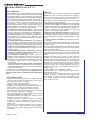
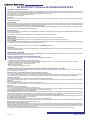
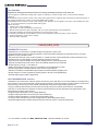
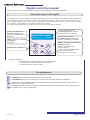
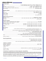
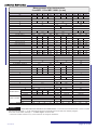
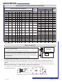
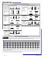
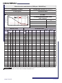
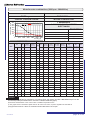
Electromechanical characteristics of the brakes
R EAR
B R AK E
delta I
lenght
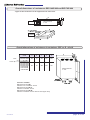
FR ON T B R AK E D OME D IMEN SION S
Measures are in mm
(w hen into brackets they are out of standard)
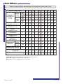
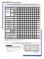
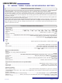
B R AK E ELEC TR IC AL D ATA
FR ON T
R EAR
POWER
AB SOR B ED
B R AK IN G
TOR QU E
POWER
AB SOR B ED
B R AK IN G
TOR QU E
MOTOR +
B R AK E
WEIGH T
MEC
G
I
O
T
F
U
L
Tongue
mm
W
Nm
W
Nm
63
60.5
95
11
23
9.5
140
115
4x4x15
/
15
5
/
/
kg
9
63L
67
110
14
30
9.5
160
128.5
5x5x20
/
20
12
/
/
12.8
71
67
110
14
30
9.5
160
128.5
5x5x20
/
20
12
/
/
14
71L
67
110
14
30
9.5
160
128.5
5x5x20
/
20
12
/
/
19.5
80
92
130
19
40
11.5
200
165
6x6x30
125
30
20
15
5
21
80L
92
130
19
40
11.5
200
165
6x6x30
130
30
20
15
5
28.5
90
92
130
24
50
12
200
165
8x7x40
90
30
20
20
8
26
90M
92
130
24
50
12
200
165
8x7x40
85
30
20
20
8
29
90L
92
130
24
50
12
200
165
8x7x40
85
30
20
20
8
32
45
40
30
16
33.4
50
(uprated)
60
(uprated)
/
/
38
45
40
30
16
54.4
50
(uprated)
60
(uprated)
/
/
59
45
40
45
35
44.4
50
(uprated)
60
(uprated)
/
/
49
45
40
45
35
54.4
50
(uprated)
60
(uprated)
/
/
59
45
40
45
35
65
100
100L
112
112L
100
180
100
180
100
180
100
180
28
28
28
28
60
60
60
60
14
14
14
14
250
250
250
250
215
215
215
215
8x7x40
8x7x40
8x7x40
8x7x40
80
85
110
110
112X
100
180
28
60
14
250
215
8x7x40
110
50
(uprated)
60
(uprated)
/
/
70
112XL
100
180
28
60
14
250
215
8x7x40
110
50
60
45
35
92
132
127
230
38
80
14
300
265
10x8x60
75
55
90
45
35- 60
77
132L
127
230(250)
38 *
80
14(16)
300(350)
265(300)
10x8x60
80
55
90
45
35- 60
102
132X L
127
230(250)
38 *
80
14(16)
300(350)
265(300)
10x8x60
/
55
90
45
35- 60
122
160
127
230(250)
38 *
80
14(16)
300(350)
265(300)
10x8x60
95
55
90
50
60
136
160L
127
230(250)
38 *
80
14(16)
300(350)
265(300)
10x8x60
95
55
90
50
60
170
160X L
127
230(250)
38 *
80
14(16)
300(350)
265(300)
10x8x60
/
55
90
50
60
180
*TEMPERED SHAFTS
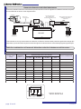
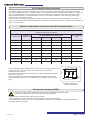
Brake connection
On the standard version with front brake, the brake has a numbered 4 pin
connector on the brake dome.
Connect the brake to terminals 1 and 2 of the connector.
On the special version with rear brake, the brake connection is available on
the services terminal block mounted by the power terminal block (see also
the paragraph Dimensional drawings of no brake motors and positions of
terminal blocks).
Power the brake at terminals 1 and 2 on the terminal block.
MOTOR WITH
FRONT BRAKE
MOTOR WITH REAR BRAKE
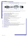
The brake operates with 24VDC. The powers are indicated in the above table.
It is always good practice to connect a flywheel diode or an R/C in parallel with the brake, especially in proximity to
appliances that are particularly sensitive to disturbance (the diode has a better filtering effect, but delays the brake
release).
N.B. if using a transformer with a 24VAC secondary winding a levelling condenser (C1) must be inserted, duly sized for the
brake powre, and up to 25W: C1 = 1000µF 35V min.; over 25W: C1 = 2000µF 35V min.
If no condenser C1 is installed a transformer with a 27VAC secondary winding must be used.
RECOMMENDED WIRING
C1=see N.B., D1=1A/400V, R1=10R/4W, R2=27R/4W , C2=0,47 uF/63V
Cat.400.INV.GB
page 27 on 40