1
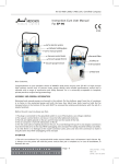
DEO-SR2 Proximity & Wiegand Card Reader with Remote Control User Manual INTRODUCTION The SR2 is a compact, weather resistant multi-function card reader that can be used as a standalone programmable access control card reader as well as a Wiegand output card reader providing proximity entry for up to 1000 users, (998 common users and 2 panic users) PIN access is also possible via the remote control unit for the Administrator and all user data can be transferred from one unit to another within 3 minutes (Maximum connection is 10 units) It reads both EM & HID card or key fob. It uses Atmel micro controller to ensure maximum performance in any environment, and the low-power circuit makes its service life prolonged The SR2’s unique feature is simple in design, easy to operate/program, and high reliability Features Weather resistant to IP66 Reads 125KHz EM & HID card or key fob One programmable relay operation Pulse mode, Latch mode relay operation Remote infrared programmer Master Add/Master Delete cards 1000 users (998 common users & 2 panic users) User data can be transferred from one unit to another Wiegand 26-37 bit input & output Card block enrolment Tri-colour LED status display Built in light dependent resistor (LDR) for anti tamper Buzzer for audible or silent mode Low temperature resistance(-40Ԩ) Specifications: User Capacity 1000 Card/key fob EM card and HID card Operating Voltage 12~24V AC/DC Idle Current <40mA Proximity Card Reader EM&HID Radio Technology 125KHz Proximity Card Read Range 2-6cm Wiring Connections Relay Output, Exit Button Relay One (NO, NC, Common) Adjustable Relay Output Time 1-99 Seconds (5 seconds default) Lock Output Load 2 Amp Maximum Environment Meets IP66 Operating Temperature -40Ԩ ~60Ԩ Operating Humidity 20%RH-98%RH Physical ABS Shell Colour Black Dimensions H: 102 W: 48 D:20mm Unit Weight 150g Shipping Weight 250g Package Contents SR2 Card Reader Infrared Remote Control Manager Cards & 10 user cards or key fobs Diode IN4004 (For relay circuit protection) Self Tapping Screws: 3*25mm Wall Anchors Screw Driver INSTALLATION Remove the back cover from the unit Drill 2 holes(A,C) on the wall for the screws and one hole for the cable Knock the supplied rubber bungs to the screw holes(A,C) Fix the back cover firmly on the wall with 4 flat head screws Thread the cable through the cable hole(B) Attach the unit to the back cover Wiring cable Wire Insulation Colour Function Notes Red Power + (AC1) Black GND Ground Pink AC2 12-24 Volts AC power input Blue NO Normally open relay output Purple COM Orange NC Normally closed relay output Yellow OPEN Request to exit input (REX) Green Data 0 Wiegand output Data 0 White Data 1 Wiegand output Data 1 Grey Alarm output Negative output for alarm Brown Contact input Door/gate input (Normally closed) 12-24 Volts AC/DC Power input Common connection for relay output Connection Diagram Examples Common power supply for magnetic lock (Fail open – power to lock) Common power supply for lock release (Fail secure – power to unlock) Common power supply for auto gate controller (using Normally Open contact) Attention: Install a 1N4004 or equivalent diode across the locking device when using a common power supply to prevent any back E.M.F as the reader might damage. (1N4004 is included in the packing) Connection to standard Wiegand controller or PC access control system Set Operation Mode – Stand-alone or Wiegand (Default is stand-alone) Programming Step Remote Control Operation 1. Enter Program Mode * (Master Code) # 2. Stand-alone Operation 72 # is factory default for stand-alone 3. Wiegand Reader Operation 73 # 4. Exit Program Mode * User data transfer connection (1 x power supply and 9 x SR2 units) Set User Data Transfer Programming Step Remote Control Operation 1. Enter Program Mode * (Master Code) # 2. Set Transfer Data on the first SR2 96 # For all 1000 users, this will take 3 minutes Within 3 minutes the green LED will shine, after 1 x bleep the LED will turn red to confirm data transfer 3. Exit Program Mode * PROGRAMMING Programming will vary depending on access confirguration. Follow the instructions according to your access configuration General Programming Information – Two ways Remote Control: Please use the Infrared Remote Control to program the Reader. The infrared receiver head is near the LED, so when you program the reader, please direct the Remote Control to the LED User ID number: Assign a user ID to the access card in order to track it. The user ID number can be any number from 0-997. IMPORTANT: User IDs do not have to be proceeded with any leading zeros Recording of User ID is crucial. Modifications to the user require the User ID to be available Proximity Card: Any 125KHz industry standard 26 bit EM and HID Proximity card or key fob Sound and Light indications Operation Status Led Colour Buzzer Stand by Red light bright - Enter into programming mode Red light shines One bleep In the programming mode Orange light bright One bleep Operation error - Three bleeps Exit from the programming mode Red light bright One bleep Open lock Green light bright One bleep Alarm ** Red light Shines quickly Bleeps ** Please see Reset Procedure for ALARM Enter and Exit Program Mode Via the Remote Control Programming Step 1. Enter Program Mode Remote Control Operation * (Master Code) # Factory default is 123456 2. Exit Program Mode * Set New Master Code Via the Remote Control Programming Step Remote Control Operation 1. Enter Program Mode * (Master Code) # 2. Enter New Master Code 0(New Master Code)#(Repeat New Master Code)# 3. Exit Program Mode * Set Operation Mode – Stand-alone or Wiegand (Default is stand-alone) Programming Step Remote Control Operation 1. Enter Program Mode * (Master Code) # 2. Stand-alone Operation 72 # is factory default for stand-alone 3. Wiegand Reader Operation 73 # 4. Exit Program Mode * Set User Data Transfer Via the Remote Control Programming Step Remote Control Operation 1. Enter Program Mode * (Master Code) # 2. Set Transfer Data on the first SR2 96 # For all 1000 users, this will take 3 minutes Within 3 minutes the green LED will shine, after 1 x bleep the LED will turn red to confirm data transfer 3. Exit Program Mode * Add User Cards Via the Remote Control Programming Step Remote Control Operation 1. Enter Program Mode * (Master Code) # 2. Add Card: Using Auto ID number 1 (Present Card) # (Allows the SR2 to assign Card to next Repeat Step 2 for additional user cards available User ID number) OR 3. Add Card: Select Specific ID number (Allows manager to define a specific User ID 1 (User ID) # (Present Card) # The user ID is any number from 0-997 to associate the card to) OR 4. Add Card: by Card Number 1 (Input the 8/10 digit Card number) # OR 5. Add Card: Block Enrolment 1 (User ID) # (Card Quantity) # (The (Allows the master card to add up to 998 first card number) # cards in a single step – this takes 2 minutes) Card or fob number MUST be consecutive 6. Exit Program Mode * Add PIN User – For Administrator for Remote Control Programming Step Remote Control Operation 1. Enter Program Mode * (Master Code) # 2. Add PIN: Via remote controller 1 (Enter PIN number, 4-6 digits) # 3. Exit Program Mode * Delete User Cards Via the Remote Control Programming Step Remote Control Operation 1. Enter Program Mode * (Master Code) # 2. Delete Card: By read card 2 (Present Card) # Repeat Step 2 for additional user cards before OR pressing the # 3. Delete Card: Select Specific ID 2 (Enter user ID number) # OR The user ID is any number from 1-998 4. Delete Card: by Card Number 2 (Input the 8/10 digits Card number) # 3. Exit Program Mode * Delete All Users Via the Remote Control Programming Step Remote Control Operation 1. Enter Program Mode * (Master Code) # 2. Delete All User Cards 2 (Master Code) # 3. Exit Program Mode * Set Relay Configuration Via the Remote Control The relay configuration sets the behaviour of the output relay on activation Programming Step Remote Control Operation 1. Enter Program Mode * (Master Code) # 2. Pulse Mode 3 (1-99) # The relay time is 1-99 seconds. (1 is 50mS.) Default is 5 seconds OR 30# 3. Latch Mode Sets the relay to ON/OFF Latch mode 4. Exit Program Mode * Set Strike-out Alarm Via the Remote Control The strike-out alarm will engage after 10 failed card attempts. Default setting is OFF. The strike-out alarm can be set to deny access for 10 minutes after engaging or it can be set to disengage only after presenting a valid user card or Master code Programming Step Remote Control Operation 1. Enter Program Mode * (Master Code) # 2. Strike-Out OFF 6 0 # (factory default) OR 3. Strike-Out ON 6 1 # Access will be denied for 10 minutes OR 4. Strike-Out ON (Alarm) Set alarm time 62# 5 (0 - 30) # factory default is 1 minute Enter Master code # or valid user card to silence 5. Exit Program Mode * Set Audible and Visual Response Via the Remote Control Programming Step Remote Control Operation 1. Enter Program Mode * (Master Code) # 2. Control LED OFF = 70 # ON = 71 # OR OFF = 74 # ON = 75 # 3. Control Sounds 4. Exit Program Mode (Factory defaults are ON) * Set Card Reading Type Via the Remote Control Programming Step Remote Control Operation 1. Enter Program Mode * (Master Code) # 2. Read EM & HID card 93 # (factory default) OR 3. Read EM card only 94 # OR 4. Read HID card only 95 # 5. Exit Program Mode * Add cards by Master Add Card Programming Step 1. Present the Master Add Card Action Present the user card/s to be added Present the Master Add Card to confirm Delete cards by Master Delete Card Programming Step 1. Present the Master Delete Card Action Present the user card/s to be deleted Present the Master Delete Card to confirm Reset Procedure Reset Alarm: The alarm will sound for 3 minutes. To reset, present a valid user card or enter * (Master Code) # via the remote control Reset to Factory Default: To reset to factory default, power off, press the Exit Button or short circuit the Black (GND) and Yellow (Open) wires, and then power on, there will be two bleeps, and the LED light will turn orange, keep this condition until you hear a long bleep after 10 seconds. The LED will turn red to confirm factory default is successful Reset to Factory Default to add new Mater Cards: To reset to factory default, power off, press the Exit Button, or short circuit the Black (GND) and Yellow (Open) wires, and then power on, there will be two bleeps, and the LED light will turn orange Release the exit button or the Black (GND) and Yellow (Open) wires, then present any two 125KHz EM cards or key fobs and the LED will turn red to confirm factory default is successful The first card presented will be the Master Add Card, and the second card will be the Master Delete Card Note: Reset to factory default, the user’s card/key fob information is still retained The SR2’s alarm trigger is activated by an LDR (Light Dependant Resistor) which is located to the rear left side of the unit as illustrated below The alarm function is designed as an ‘Anti‐Theft’ facility which cannot be disabled but it can be stopped by presenting a valid card or key fob to the reader or entering the Master Code followed by the # sign via the remote Alternatively, you can prevent the alarm from activating by covering the LDR with a non‐light absorbent substance. Black paint or a small amount of ‘Blu‐Tack’ will work perfectly fine This is the LDR (Light Dependent Resistor). The LDR is the SR2’s Alarm Trigger Sensor and activated by light