1
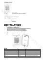
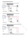
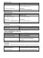
KP-401-A Internal AC Stand-Alone Keypad C S ES (Proximity Ready) C SE Y IT R U TS C U D O PR D LT User Manual INTRODUCTION The K401-I is a single relay multifunction standalone access control keypad suitable for indoor use. It is housed in a strong, sturdy and vandal resistant Zinc Alloy electroplated case It supports up to 1000 users in a Card, PIN, or a Card + PIN option. The inbuilt card reader supports 125KHZ EM frequency card or key fob, and the Pin length is 4-6 digits The single relay can operate in Pulse Mode (suitable for access control) or Toggle Mode (suitable for AC arming/disarming alarms, switching lights, machines….etc) The K401-I has many extra features including block enrollment, anti-tamper alarm & backlit keypad buttons These features make the K401-I an ideal choice for door access not only for small shops and domestic C households but also for commercial and industrial applications such as factories, warehouses, laboratories, S ES banks and prisons Features Vandal resistant enclosure Backlit Keypad buttons Multi-color LED status display One programmable relay output 1000 Users (Card/PIN/Card & PIN) Low power consumption (50mA) Anti-Tamper Alarm Latch Mode to hold door or gate open 12-24V DC Power input C SE User Capacity Operating Voltage Y IT R U Specifications: 1000 Cards/PINS 12-24V DC 50mA Active Current 80mA Keypad 12 Key (3*4) Proximity Card Reader EM O PR Idle Current 125 KHz Industry Standard Proximity Card Read Range 25mm-35mm Wiring Connections Relay Output, Exit Button Relay One (NO, NC, Common) Adjustable Relay Output Time 1-99 Seconds (5 seconds default) Lock Output Load 3 Amp Maximum Environment Indoor -30℃ - 60℃ Operating Humidity 20%RH-85%RH Physical Zinc-Alloy Enclosure Powder Coat Dimensions L: 120 x W: 76 x D: 25 (mm) Unit Weight 490g Shipping Weight 600g D Surface Finish LT Operating Temperature TS C U D Radio Technology Package contents AC K401-I Keypad C Diode IN4004 (For relay circuit protection) S ES Self Tapping Screws Wall Anchors C SE Screw Driver R U INSTALLATION Remove the back cover from the unit Drill 2 holes (A,C) on the wall for the screws and one hole for the cable Knock the supplied rubber bungs to the screw holes (A,C) Fix the back cover firmly on the wall with 4 flat head screws Thread the cable through the cable hole (B) Attach the unit to the back cover Y IT TS C U D O PR Wire Insulation Colour Function Notes Yellow OPEN Request to Exit input (REX) Red Power + 12-24V DC Regulated Power Input Black GND Ground Blue NO Normally Open Relay Output Purple COM Common Connection for Relay Output Orange NC Normally Closed Relay Output D LT Wiring Connection Diagram Examples Common power supply for magnetic lock (Fail open – power to lock) C AC S ES C SE Common power supply for lock release (Fail secure – power to unlock) Y IT R U C U D O PR Common power supply for auto gate controller (using Normally Open contact) TS D LT Attention: Install a 1N4004 or equivalent diode across the locking device when using a common power supply to prevent any back E.M.F as the reader might damage. (1N4004 is included in the packing) PROGRAMMING Programming will vary depending on access confirguration. Follow the instructions according to your access configuration Programming 1 -------------------- Configure the K401-I Change the configure settings according to your application (optional). Multiple configuration settings can be AC changed at one time: enter program mode, change the desired settings, then exit program mode Set Master Code C The 4-6 digit Master Code is used to prevent unauthorized access to the system. To interface with the K401-I, S ES the manager will need a Master Code (factory default code: 6666). We recommend immediate update and recording of your Master Code Programming Step Keystroke Combination ﹡(Master Code) # 2. Update Master Code 0(New Master Code)#(Repeat New Master Code)# 3. Exit Program Mode * C SE 1. Enter Program Mode SET ACCESS CONFIGURATION There are 3 types of access configurations for the K401-I U • Card or PIN (Default): The User must present a valid Card to the K401-I or enter their PIN code followed R by the # key, in order to be granted access • Card Only: The User must present a valid Card to the K401-I in order to be granted access Y IT • Card + PIN: The User must first present a valid Card to the K401-I and then enter their PIN code followed by the # key, in order to be granted access Programming Step Keystroke Combination PR ﹡(Master Code) # 2. Card or PIN 3 0 # (Default) 3. Card + PIN 31# 4. Card only 32# 5. Exit program mode * Set Relay Configuration The relay configuration sets the behaviour of the output relay on activation Programming Step Keystroke Combination TS C U D O 1. Enter Program Mode ﹡(Master Code) # 2. Pulse Mode 4 (1-99) # The relay time is 1-99 seconds. (1 is 50ms) Default is 5 seconds 3. Latch Mode 4 0 # Sets the relay to ON/OFF Latch mode 4. Exit program mode * D LT 1. Enter Program Mode Set Strike-out Alarm The strike-our alarm will engage after 5 failed card/PIN attempts. Factory default is OFF. The strike-our alarm can be set to deny access for 10 minutes after engaging or it can be set disengage only after entering a valid card/PIN or Master Code Programming Step Keystroke Combination ﹡(Master Code) # 2. Strike-Out OFF 6 0 # (Default) 3. Strike-Out ON 6 1 # Access will be denied for 10 minutes 4. Strike-Out ON 6 2 # The buzzer alarms C AC 1. Enter Program Mode 5 (0 - 30) # (Default is 1 minute) 6. Exit program mode * S ES 5. Set alarm time C SE Programming 2 -------------------- Program Cards and PINS Programming will vary depending on the access configuration. Follow the instructions according to your access R U configuration Y IT GENERAL PROGRAMMING INFORMATION • User ID Number: Assign a user ID number to the access code in order to keep track of the users of access cards or PINS. The user ID number can be any number from 1-1000 PR I M P ORTANT: User IDs do not have to be proceeded with any leading zeros. Recording of User ID is critical Modifications to user data require either the card or the User ID be available O factory testing) ACCESS CONFIGURATION: CARD OR PIN & CARD ONLY Add User Cards Programming Step Keystroke Combination ﹡(Master Code) # 2. Add Card: Using Auto ID 1 (Read Card) # 3. Add Card: Select Specific ID (Allows manager to define a specific User ID to associate the card to) 4. Exit program mode Cards can be added continuously D (Allows K401-I to assign Card to next available User ID number) LT 1. Enter Program Mode TS C U D • Proximity Card: 125 KHz industry standard 26 bit EM Proximity Card • Keypad PIN: The PIN can be any 4-6 digits between 0000-999999 (except 1234 which is reserved for 1 (User ID) # (Read Card) # The user ID is any number from 0-999 * Delete User Cards Programming Step Keystroke Combination 1. Enter Program Mode ﹡(Master Code) # 2. Delete Card: By card 2 (Read Card) # Cards can be deleted continuously 2 (User ID) # 3. Delete Card: Select Specific ID The user ID is any number from 0-999 * AC 4. Exit program mode C Add or Delete a PIN Programming Step Keystroke Combination ﹡(Master Code) # 2. Add a PIN 1 (User ID) # (PIN) # Assigns PIN to user ID number PINS can be added continuously 3. Delete a PIN 2 (User ID) # S ES 1. Enter Program Mode C SE Deletes the User ID number and associated PIN PINS can be deleted continuously 4. Exit program mode * U Change a PIN Programming Step 2. Exit program mode Keystroke Combination Y IT 1. Change a PIN R This operation is executed from outside of Program Mode ﹡(User ID#) (Old PIN #) (New PIN #) (New PIN #) * Add a Card+ PIN User Programming Step PR ACCESS CONFIGURATION: CARD+PIN Keystroke Combination ﹡(Master Code) # 2. Add a User Card by ID number 1 (User ID) # (Read Card) # 3. Exit Program Mode * 4. Add PIN * (Read Card) (1234#) (New PIN #) (New PIN #) C U D O 1. Enter Program Mode This operation is executed from outside of Program Mode * Change PIN TS 5. Exit program mode Program Mode Programming Step Keystroke Combination 1. Change PIN using a Card (Read Card) (Old PIN #) (New PIN #) (New PIN #) 2. Change PIN using PIN (User ID) (Old PIN #) (New PIN #) (New PIN #) 3. Exit program mode * D LT Allows card user to update the PIN for their card + PIN User ID. This operation is executed from outside of Delete Card by User ID Deleting by ID number will clear cards and PINS Programming Step Keystroke Combination 1. Enter Program Mode ﹡(Master Code) # 2. Delete User Card by User ID 2 (User ID) # 3. Exit program mode * AC C Others S ES Reset to Factory Default: This will reset the K401-I to factory default but all card/PIN information will still be retained 1. Power the K401-I down 2. Press and hold the * button and power up the K401-I reset C SE 3. There will be two bleeps. Then release the * button, after a second there will be one more bleep to confirm Erase all Cards U This will delete ALL User data 2. Press 20000 # All configuration data is retained Reset Strike-Out Alarm Y IT 3. Exit: * R 1. Enter Program Mode: *(Master Code) # Sound and Light indication C U D O PR Enter Master Code or Valid Card/PIN to silence Operation Status Red LED Green LED Power on Flashing Stand by Flashing Press Keypad Flashing Enter Master Code Entry Mode ON In program mode ON Single Flash Short Single Bleep Entered Program Step Successfully ON Single Flash Short Single Bleep Short Single Bleep TS Short Single Bleep Short Single Bleep LT Entered Program Step Incorrectly Exit from the programming mode Sounds 3 Short Bleeps Flashing ON Short Single Bleep Open lock Green light bright One Bleep Alarm Mode Engaged Flashing Alarm Alarm Red light Shines quickly Bleeps Pressing * Toggles Standby / Master ON/Flashing Short Single Bleep Code Entry D Entry Granted Short Single Bleep K401-I- Simplified Instruction Function Description Operation Enter the Programming Mode * (Master Code) # AC (6666 is the default factory master code) 0(New Master Code)#(Repeat New Master Code)# Change the Master Code (code: 4-6 digits) C 1 (Read Card) # Add Card User S ES 1 (User ID) # (PIN) # Add PIN User The ID number is any number between 0 - 999.The PIN is any 4-6 digits between 0000 - 999999 2 (Read Card) # Delete User C SE Exit from the programming mode 2 (User ID) # * Card User Read card R PIN User U How to be granted access Enter (PIN) # Y IT TS C U D O PR D LT