1
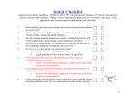
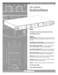
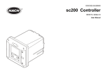
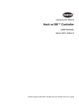
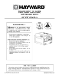
PN: ISVR1000TECH Rev: J _____________________________________________________________________________________________________________________________________ MODEL VR1000 SERVICE MANUAL INSTALLATION & PARTS WARNING – Improper installation, use, or maintenance of this Vacuum Release System or associated equipment could cause serious or fatal injury. To reduce the risk of injury, read and follow all instructions in this Manual and on the equipment. Make sure installation and any maintenance necessary are done by people who are qualified and have the proper equipment to do the job right. All electrical wiring MUST be in conformance with all applicable local codes, regulations, and the National Electrical Code (NEC). Basic safety precautions should always be followed, including the following: Failure to follow instructions can cause severe injury and/or death. This is the safety-alert symbol. When you see this symbol on your equipment or in this manual, look for one of the following signal words and be alert to the potential for personal injury. WARNING warns about hazards that could cause serious personal injury, death or major property damage and if ignored presents a potential hazard. CAUTION warns about hazards that will or can cause minor or moderate personal injury and/or property damage and if ignored presents a potential hazard. It can also make consumers aware of actions that are unpredictable and unsafe. The NOTICE label indicates special instructions that are important but not related to hazards. USE ONLY HAYWARD GENUINE REPLACEMENT PARTS Pomona, CA Clemmons, NC Nashville, TN Tel: 908.351.5400 www.haywardpool.com Page 2 of 24 STRATUM™ Model VR1000 P/N: ISVR1000TECH Rev: J READ AND FOLLOW ALL INSTRUCTIONS IN THIS SERVICE AND INSTALLATION MANUAL AND ON EQUIPMENT. IMPORTANT SAFETY INSTRUCTIONS Before installing or servicing this electrical equipment, turn power supply OFF. KEEP SAFETY LABELS IN GOOD CONDITION AND REPLACE IF MISSING OR DAMAGED. WARNING – To reduce risk of injury, do not permit children to use or climb on the pumps and filters. Closely supervise children at all times. Components such as the filtration system, pumps, and heaters must be positioned to prevent children from using them as a means of access to the pool. CAUTION – This vacuum release system is intended for use on permanently installed swimming pools and may also be used with hot tubs and spas. Do NOT use with storable pools. A permanently installed pool is constructed in or on the ground or in a building such that it cannot be readily disassembled for storage. A storable pool is constructed so that it is capable of being readily disassembled for storage and reassembled to its original integrity. Though this product is designed for outdoor use, it is strongly recommended to protect the electrical components from the weather. Select a welldrained area, one that will not flood when it rains. It requires free circulation of air for cooling. Do not install in a damp or non-ventilated location. If installed within an outer enclosure or beneath the skirt of a hot tub or spa, adequate ventilation and free circulation of air must be provided to prevent overheating of the components. WARNING – All electrical wiring MUST be in conformance with all applicable local codes, regulations, and the National Electrical Code (NEC). Risk of Electric Shock. Hazardous voltage can shock, burn, cause death or serious property damage. To reduce the risk of electric shock, do NOT use an extension cord to connect unit to electric supply. Provide a properly located outlet. All electrical wiring MUST be in conformance with applicable local and national codes and regulations. Before working on pump or motor, turn off power supply to the pump. WARNING – To reduce the risk of electric shock replace damaged wiring immediately. Locate conduit to prevent abuse from lawn mowers, hedge trimmers and other equipment. WARNING – All electrical wiring MUST be in conformance with all applicable local codes, regulations, and the National Electrical Code (NEC) including a Ground Fault Circuit Interrupter (GFCI) in circuit. For size of GFCI required and test procedures for GFCI, see manufacturer’s instructions. Pump MUST be permanently connected to GFCI. WARNING – Failure to bond pump to pool structure will increase risk for electrocution and could result in injury or death. To reduce the risk of electric shock, the electrician must comply with installation instructions and must bond the pump accordingly. In addition, the electrician must also conform to local electrical codes for bonding requirements. Notes to the electrician: Use a solid copper conductor, size 8 or larger. Run a continuous wire from external bonding lug to reinforcing rod or mesh. Connect a No. 8 AWG (8.4 mm2) solid copper bonding wire to the pressure wire connector provided on the motor housing and to all metal parts of swimming pool, spa, or hot tub, and to all electrical equipment, metal piping (except gas piping), and conduit within 5 ft. (1.5 m) of inside walls of swimming pool, spa, or hot tub. IMPORTANT - Reference NEC codes for all wiring standards including, but not limited to, grounding, bonding and other general wiring procedures. NOTE - The National Electrical Code (NEC) permits use of a cord with a maximum 3 ft. (1 m) length. If your pump is equipped with a cord complying with the NEC, the preceding four (4) hazards apply. WARNING – Suction Entrapment Hazard. Suction in suction outlets and/or suction outlet covers which are, damaged, broken, cracked, missing, or unsecured can cause severe injury and/or death due to the following entrapment hazards: Hair Entrapment- Hair can become entangled in suction outlets. Limb Entrapment- A limb inserted into an opening of a suction outlet or suction outlet cover that is damaged, broken, cracked, missing, or not securely attached can result in a mechanical bind or swelling of the limb. Body Suction Entrapment- A differential pressure applied to a large portion of the body or limbs can result in an entrapment. Evisceration/ Disembowelment - A negative pressure applied directly to the intestines through an unprotected suction outlet sump or suction outlet cover which is damaged, broken, cracked, missing, or unsecured can result in evisceration (disembowelment). Mechanical Entrapment- There is potential for jewelry, swimsuit, hair decorations, finger, toe or knuckle to be caught in an opening of a suction outlet or suction outlet cover resulting in mechanical entrapment. USE ONLY HAYWARD GENUINE REPLACEMENT PARTS Pomona, CA Clemmons, NC Nashville, TN Tel: 908.351.5400 www.haywardpool.com Page 3 of 24 P/N: ISVR1000TECH Rev: J STRATUM™ Model VR1000 WARNING - To reduce the risk of entrapment hazards: o When suction outlets are less than a 18” x 23” equivalent, a minimum of two functioning ASME112.19.8 suction outlets per pump must be installed. Suction outlets in the same plane (i.e. floor or wall), must be installed a minimum of three feet (3’) [1 meter] apart, as measured from near point to near point. o Dual suction outlets shall be placed in such locations and distances to avoid “dual blockage” by a user. o Dual suction fittings shall not be located on seating areas or on the backrest for such seating areas. o The maximum system flow rate shall not exceed the flow rating of any listed (per current revision of ASME/ANSI A112.19.8) suction outlet cover installed. o Never use the Pool or Spa if any suction outlet component is damaged, broken, cracked, missing, or not securely attached. o Replace damaged, broken, cracked, missing, or not securely attached suction outlet components immediately. o In addition two or more suction outlets per pump installed in accordance with latest APSP (formally NSPI) Standards and CPSC guidelines, follow all National, State, and Local codes applicable. This vacuum release system is designed to prevent body suction entrapment, but not evisceration. WARNING – Failure to remove pressure test plugs and/or plugs used in winterization of the pool/spa from the suction outlets can result in an increase potential for suction entrapment as described above. WARNING – Failure to keep suction outlet components clear of debris, such as leaves, dirt, hair, paper and other material can result in an increase potential for suction entrapment as described above. WARNING – Suction outlet components have a finite life, the cover/grate should be inspected frequently and replaced at least every ten years or if found to be damaged, broken, cracked, missing, or not securely attached. WARNING – All suction and discharge valves MUST be OPEN when starting the circulation system. Failure to do so could result in severe personal injury and/or property damage. All drains and suction outlets MUST have properly installed covers, securely attached using the screws supplied with the covers. If screws are lost, order replacement parts from your supplier. WARNING – Hazardous Pressure. Pool and spa water circulation systems operate under hazardous pressure during start up, normal operation, and after pump shut off. Stand clear of circulation system equipment during pump start up. Failure to follow safety and operation instructions could result in violent separation of the pump housing and cover due to pressure in the system, which could cause property damage, severe personal injury, or death. Before servicing pool and spa water circulation system, all system and pump controls must be in off position and filter manual air relief valve must be in open position. Before starting system pump, all system valves must be set in a position to allow system water to return back to the pool. Do not change filter control valve position while system pump is running. Before starting system pump, fully open filter manual air relief valve. Do not close filter manual air relief valve until a steady stream of water (not air or air and water) is discharged. WARNING – Separation Hazard. Failure to follow safety and operation instructions could result in violent separation of pump components. Strainer cover must be properly secured to pump housing with strainer cover lock ring. Before servicing pool and spa circulation system, manual air relief valve must be in open position. Do not operate pool and spa circulation system if a system component is not assembled properly, damaged, or missing. Do not operate pool and spa circulation system unless filter air relief valve body is in locked position in filter upper body. WARNING – Never operate or test the circulation system at more than 40 PSI. WARNING – Fire and burn hazard. Motors operate at high temperatures and if they are not properly isolated from any flammable structures or foreign debris they can cause fires, which may cause severe personal injury or death. It is also necessary to allow the motor to cool for at least 20 minutes prior to maintenance to minimize the risk of burns. WARNING – Failure to install according to defined instructions may result in severe personal injury or death. DEFINITIONS: Suction Outlet – The term Suction Outlet is a fitting, fitting assembly, cover/grate and related components that provide a means for water to exit the pool and into the pump circulating system. Inches of Mercury (in Hg) - A unit for measuring pressure below atmospheric (“suction” or “vacuum”) (1.0 inch Hg = .491 PSI) Main Drain – See Suction Outlet PSI – An abbreviation for pounds per square inch. USE ONLY HAYWARD GENUINE REPLACEMENT PARTS Pomona, CA Clemmons, NC Nashville, TN Tel: 908.351.5400 www.haywardpool.com Page 4 of 24 STRATUM™ Model VR1000 P/N: ISVR1000TECH Rev: J General Information: The VR1000 Vacuum Release System is designed as a pump controller. The system will protect pool and spa equipment from certain known mechanical failures, such as clogged drains and pipe breakage; which can cause premature pump motor failure. The system monitors and recognizes a change in pressure and electrical power. When a change occurs, it will shut down the pump, and vent the suction line. Automatic soft start should provide notice to swimmers or bathers on pump startup. The VR1000 meets the requirements of ASTM Specification F2387-04. Meets ASME Standard 112.19.17. Meets UL standard 1563 as well as certified to Can/CSA Std. C27.2 No. 218.1. The VR1000 system will automatically restart in most instances. Should a manual restart be required, pressing the “OK” button will restart the system. “Unprotected” Mode can be entered, after restart, by holding “NO” & “OK” buttons. “Unprotected” mode lasts 30 minutes, providing NO protection for swimmers or bathers. DO NOT ALLOW SWIMMERS OR BATHERS IN THE POOL OR SPA WHEN THE SYSTEM IS IN “UNPROTECTED” MODE. For proper installation and to avoid unnecessary service calls, read this manual carefully and completely. WARNING – This product should be installed and serviced only by a qualified professional. Failure to install and/or operate according to defined instructions and/or use of non-Hayward replacement parts will void the warranty. CAUTION – All electrical wiring MUST be in conformance with all applicable local codes, regulations, and the National Electrical Code (NEC). Introduction: This manual contains information for the proper installation and operation of the Hayward VR1000 Vacuum Release System. The instructions in this manual MUST be followed precisely. NOTICE – ALL PRESSURE TESTING OF THE SYSTEM MUST BE COMPLETED BEFORE INSTALLING THE STRATUM™. NOTICE – The filter must be cleaned or cartridge replaced before installing the STRATUM™. NOTICE –The STRATUM™ is rated for 115 VAC 50/60Hz for up to a 1 horsepower pump motor or 208/230 VAC 50/60Hz for up to a 3 horsepower pump motor. FIG 1 USE ONLY HAYWARD GENUINE REPLACEMENT PARTS Pomona, CA Clemmons, NC Nashville, TN Tel: 908.351.5400 www.haywardpool.com Page 5 of 24 P/N: ISVR1000TECH Rev: J STRATUM™ Model VR1000 Installation Instructions DIP Switches Battery BR2032 FIG 2. FIG 3 LIST OF NEEDED ITEMS FOR INSTALLATION 1. 2. 3. 4. VR1000 system Location on vertical surface to install the VR1000 within ten feet of the pump and above the pump. 25’ length of tubing (Supplied in package.) For Pipe installation, a. 3/8” electric drill b. 3/8” drill bit c. Saddle Gasket CL220C (Supplied in package.) d. Saddle Fitting CL220G (Supplied in package.) e. Saddle Clamp CL220K (Supplied in package.) f. Ferrule Nut and Ferrule (Supplied in package.) 5. Adjustable wrench 6. #2 Phillips screw driver 7. Small bladed screw driver 8. Large bladed screw driver Mounting hardware for VR1000 Electrical box (Not Supplied) MECHANICAL MOUNTING INSTRUCTIONS FOR INGROUND POOLS WITHOUT FLOODED SUCTION. Note: If the installation is for an above ground pool or for flooded suction, the VRX100F assembly is suggested. The VR1000 is designed to be used on a single pump or a combination of a single pump with a booster pump, on a common suction line. 1. 2. 3. 4. 5. TURN OFF THE ELECTRICAL POWER AT THE CIRCUIT BREAKER. Remove all check valves from the suction lines of the Pool/Spa system. WARNING- Check Valves must be removed from the circulation systems. The presence of a check valve used to carry the water flow within the circulation system has been shown to prolong the high vacuum present at the drain, even though the drain is protected by a SVRS. For this reason, check valves which carry the water flow within the circulation system must be removed. For installation of the vacuum sensing tube into the suction line of the pump: (See Page 17 for additional pictures) a. Locate a straight section of pipe approximately one foot long, as close to the inlet of the pump as practical. b. On this straight pipe about in the middle, go 45º from the top. (This will minimize the air entrapment in the system and help keep the system stable.) Drill a 3/8” hole. (See FIG 2) c. Install the Saddle Gasket on the end of the Saddle fitting. Place the assembly in the drilled hole. Place the saddle clamp over the saddle fitting. Tighten the Saddle clamp to assure a leak free joint. DO NOT OVERTIGHTEN. Find a location for the VR1000 on a wall, or post, out of the direct sunlight, which will not be flooded, and above the pump. If the box is mounted below the water level, the vent should be extended to above the water level. Place the Ferrule Nut over the tubing. (See FIG 2) Make sure the tubing bottoms out in the saddle fitting. Holding the tubing in place, tighten the Ferrule Nut firmly by hand. DO NOT OVERTIGHTEN. Run the 5/16” vacuum tube from the fitting on the suction line to the fitting on the VR1000 unit. Make sure the vacuum tubing has no kinks and is strain free. The fitting on the STRATUM™ does not require tooling to install the tubing. Just insert the end of the tubing firmly into the fitting, a slight pull should not dislodge the tubing. USE ONLY HAYWARD GENUINE REPLACEMENT PARTS Pomona, CA Clemmons, NC Nashville, TN Tel: 908.351.5400 www.haywardpool.com Page 6 of 24 STRATUM™ Model VR1000 P/N: ISVR1000TECH Rev: J INITIAL REQUIRED SETTINGS: 1. 2. 3. 4. 5. 6. 7. 8. 9. The VR1000 unit is factory set for 230VAC input. Leave the switch in this “FACTORY SET” position unless a low voltage error occurs, in which case turn the power off, and move the switch to 115VAC. NOTICE: THE CIRCUIT BOARD AND COMPONENTS MAY BE DAMAGED IF 208/230 VAC IS APPLIED TO THE BOARD WHEN THE “SWITCH” IS IN THE 115VAC POSITION. The VR1000 is factory set to English, the following three language settings are available by adjusting the dip switches 1, 2 at the top of the board: A “ON” setting is down and toward the board. Please use a pen or pencil to gently move the switch as required. See Fig 3 Language 1 2 3 4 5 6 7 8 English OFF OFF 2-Speed Pump Timers Manufacturing Test Booster Pump Specials Pinch Test Spanish ON OFF French OFF ON To activate the component test, set Dip Switch 5 to ON. (This should NEVER be done unless directed to do so by Hayward Technical Service.) For 2 Speed pumps, set Dip Switch 3 to ON. Special wiring required. (See FIG 6) To activate the timer cycle, set Dip Switch 4 to ON. To activate the Booster Pump Timer, Set Dip Switch 6 to ON. Dip Switch 7 is for Welded Contactor settings and High lift situations. (See Page 19) Must be set for flooded suction. Dip Switch 8 performs special functions related to the detection of a pinched vacuum tube. After the pinched tube settings have been made this switch should be turned to the OFF position to disable the screens (but not the function). ELECTRICAL CONNECTION INSTRUCTIONS: 1. 2. ASSURE POWER IS DISCONNECTED FROM SOURCE. To install optional contactors the factory-installed wires attached must be connected to the proper terminals on the circuit board. For a booster pump always use motor relay 3 on the board as shown in FIG. 4. 3. Connect pump to contactor terminals 4 & 8 (See FIG 7). If a booster pump is used, with a pool cleaner, connect this pump to 4 & 8 on a second contactor (Optional Contactor VRX100KIT). The contactor control (2 wires supplied) MUST be connected onto the board next to the solenoid valve terminals, that is, in motor relay position 3. One reason to connect the booster pump through this system is to protect the booster pump motor from burn out if the VR1000 were to stop the primary filter pump. Additionally the timers can then be used to control the timing of the Booster pump. 4. If a two-speed pump is used connect the “Low Speed” to terminals 4 & 8 on a contactor (Optional Contactor VRX100KIT). The contactor control (2 wires supplied) MUST be connected onto the board in motor relay position 2. NOTE: If the pump horsepower is greater than 3 HP, the contactors can be used in series with the motor starters. (See Illustration below FIG 8) 5. Connect a ground wire from the primary electrical panel to the VR1000 and connect the system to the pool bonding system by an 8AWG (6AWG for Canada) wire. A lug for bonding is provided on the outside/bottom of the enclosure. 6. Connect incoming power to 2&6 on the power relay(s) (See FIG 7). Assure that the earth ground wire connector between the conductors is secured. 7. (Optional) If a remote stop button is used, remove jumper from terminal pair marked “STOP Switch”. The switch must be a “locking type “STOP” switch with a normally closed set of contacts in the “UP” position. Install the “STOP” switch across the terminals where jumper was located. A Steward 28A0640-0A0-1/2 turn ferrite core or equal must be added to the stop switch cable within 2” of the outside of the STRATUM™ box. (Stop switch can be Square D # KR9RH6 or equivalent mounted in a rain tight box.) 8. (Optional) If a remote alarm is to be installed, the terminals “Buzzer” are connected to an alarm relay which will supply a closed contact rated at 115 VAC, 5 amp, when the system alarm trips. External power must be supplied for the alarm to sound. Can be used with Audible Alarms from Federal Signal Model 350-120-30 or equivalent available from Grainger. 9. The terminal marked “SPARE” when connected to the terminal marked “GROUND” will turn the pump on to “High Speed” and maintain the “High Speed” mode until these two terminals are disconnected. Thus if a “Manual” override is desired a maintained contact switch can be used to between these terminals. 10. For Flooded Suction and Pumps located more than 3’ above the pool turn on Dip Switch 7.(See Page 19) 11. Replace the inner barrier and secure with two screws included. 12. Power should be applied to the system while watching the display. Follow the directions on the display. This operation will confirm the available voltage is suitable for proper operation of the VR system. NOTICE: THE CIRCUIT BOARD AND COMPONENTS MAY BE DAMAGED IF 208/230VAC IS APPLIED TO THE BOARD WHEN THE “SWITCH” IS IN THE 115VAC POSITION. 13. Close the electrical enclosure. 14. Apply power to system. USE ONLY HAYWARD GENUINE REPLACEMENT PARTS Pomona, CA Clemmons, NC Nashville, TN Tel: 908.351.5400 www.haywardpool.com Page 7 of 24 STRATUM™ Model VR1000 P/N: ISVR1000TECH Rev: J FIG 5 Internal Control External FIG 4 Aqua Logic FIG 6 Internal Control FIG 7 Aqua Logic FIG 8 THREE PHASE PUMP MOTOR SUGGESTED CONNECTION USE ONLY HAYWARD GENUINE REPLACEMENT PARTS Pomona, CA Clemmons, NC Nashville, TN Tel: 908.351.5400 www.haywardpool.com Page 8 of 24 P/N: ISVR1000TECH Rev: J STRATUM™ Model VR1000 Note: For Flooded Suction and Pumps installed more than 3’ above the surface of the pool Turn on Dip Switch 7 before Appling power to the STRATUM™ (See Page 19) VR1000 VER X.X Initial Start OK INITIAL SCREENS: These will disappear after the Initial Set up is complete. The start delay allows the installer to be ready for the system to start. During initial start-up and set-up the start delay should not be disabled. A press of the “OK” button will start the system. Answering “YES” will allow the system to restart during normal operation. Answering “No” will cause the system to come up to the “VR1000 VER XX Initial Start OK” screen above and stop, when there is a loss of power. Initial Set-up Complete? Y/N SCREENS ON VR1000 For the set-up of the VR1000 we recommend that the system be placed in the “Unprotected mode”, which does not protected swimmers or bathers from entrapment. It does allow the system to read the vacuum in various plumbing configurations. HAYWARD POOL PRODUCTS Unprotected Mode Entry Y/N Press “NO” and “Menu” simultaneously and hold in until the screen changes to place system in “Unprotected mode”. Answer “Yes”. WARNING - Body Suction Entrapment Hazard Suction in suction outlets can cause severe injury and/or death due to a differential pressure applied to a large portion of the body or limbs. STRATUM™ “Unprotected” Mode: Is when the pump is operating and the STRATUM™ is NOT providing any protection against Body Suction Entrapment. Do Not allow Swimmers and Bathers in the pool and spa when the STRATUM™ is in “Unprotected” mode. The STRATUM™ only provides a layer of protection against Body Suction Entrapment in monitoring mode. NOTICE: The STRATUM™ will beep to indicate the unit is in unprotected mode. No Swimmers Allow In pool/Spa Is Anyone in Pool or Spa? Y/N Unprotected Mode Press OK to End Various configurations of the plumbing system for the Pool and Spa should be should be set-up with the resulting vacuum level recorded. (See “Run and Record” Work Sheet page 17.) Set up the Pool or Spa in the plumbing configuration that showed the lowest vacuum level for column (B). This configuration should be used for the initiation of the VR1000. Pressing “YES” will not allow activation mode and return you to the TECH Mode Screen Pressing “No” will allow the system to go into “Unprotected” Mode for 30 minutes. To stop “Unprotected” mode before the 30 minute period has expired press “OK”. These two screens alternate and are for information purposes only. Unprotected Pool Vacuum = X.X Exiting Unprotected Mode USE ONLY HAYWARD GENUINE REPLACEMENT PARTS Pomona, CA Clemmons, NC Nashville, TN Tel: 908.351.5400 www.haywardpool.com Page 9 of 24 STRATUM™ Model VR1000 P/N: ISVR1000TECH Rev: J This displays the current time and date. The system was initiated in the Eastern Time Zone. 02-02-06 12:00 P.M. SET TIMER EVENTS Y/N It is required that the time of day clock be changed on first start-up. Even if this change is forward a minute and then back.. (If the date and time are not maintained from the last time it was set, the battery may need to be replaced.) “YES” follow screen instructions SET TIMER EVENTS is the only used when the VR1000 has been set to allow control of pump on/off times.(or with use of a 2-speed pump) See Page 10 for screen information. SET TIME AND DATE? Y/N SELECT POOL TECH. MODE? Y/N For the Start-up, Set-up of the VR1000, it is recommended that the “Custom Install Procedures” be run, before the system is allowed to find its initial “Prime Vacuum Value.” Rapidly Push the “Menu” button twice. (See Custom Install Procedures” on page 14.) SCREENS showing errors and exceptions: VR1000 VER X.X STOP SWITCH The system will not start if the optional “STOP Switch” is pressed in. Action Required: Reset “STOP Switch” VR1000 VER X.X S/S VENT ERROR Sensor/Solenoid Venting Error. Remove and clean or replace the vent plug. (This is the cone shaped device on the exterior/bottom of the box.) (See Fig 1) If vent cleaning/replacement does not correct the problem, replace the solenoid valve (See Fig 9). VR1000 VER X.X NO STABILIZATION “No Stabilization" indicates that there is likely a problem with the pump. The pump basket should be checked for debris. Other pumping issues can cause stabilization problems. VR1000 VER X.X SELF TEST Self Test Indicates the system is checking itself for proper operation of its components. No Customer Action is required. VR1000 OVER WINDOW VACUUM Over Window Vacuum indicates a vacuum level detected that is above normal for the pool system. The system should restart. VR1000 UNDER WINDOW VACUUM Under Vacuum Window indicates a problem with the inlet water flow to the pump. Low volume flow can be caused by line breaks, or low water levels. The system should restart. HIGH VACUUM ALERT High Vacuum Alert indicates the system has stopped the pump, vented, and set off the alarm. CUSTOMER ACTION IS REQUIRED. Clear the cause of the problem. Then press the “OK” button to restart the system. SYSTEM WON'T STABILIZE System Won't Stabilize indicates the system has stopped the pump three times and set off the alarm. CUSTOM ACTION IS REQUIRED. Clear the cause of the problem. Then press the “OK” button to restart the system. TOO MANY SEN/SOL ERRS OR NO PRIME Too Many Sen/Sol Errs Or No Prime indicates the system has vented and stopped the pump three times and set off the alarm. CUSTOM ACTION IS REQUIRED. Clear the cause of the problem. Then press the “OK” button to restart the system. USE ONLY HAYWARD GENUINE REPLACEMENT PARTS Pomona, CA Clemmons, NC Nashville, TN Tel: 908.351.5400 www.haywardpool.com Page 10 of 24 P/N: ISVR1000TECH Rev: J STRATUM™ Model VR1000 CUSTOMER ACCESSIBLE MODES To initiate a self-test through the use of the push buttons on the display push button “OK/MENU” and release. This only causes the system test in “RUN MODE”. The self test is run by the customer just to confirm the VR1000 is actively protecting the pool/spa. The system should restart and stabilize. Set the time of day clock. In normal operation the time of day will be displayed on the LCD. When the board is first powered up the time and date are displayed. Pushing the “Menu” button will step through the date and time of day set up. Pushing the “NO” will go to next step. (5 Seconds of inactivity will go to next step.)“YES” follow screen instructions. NOTE: If system does not maintain date and time when the power fails or is disconnected, replace the battery. The timer events are used to control the ON and OFF times of the Filter Pump, Booster Pump and Low SET TIMER Speed on a two speed Pump. Dip switch #4 Must be on to allow the timers to be set. A “YES” will allow the following timer settings. Note: Timers run 12:01 AM (Midnight) to 11:59 PM. EVENTS? Y/N SET TIME AND DATE? Y/N “YES” 7-day all the week long the pumps will run at the same times. Y= 7 Day Mode N= Each Day Mode ON = 04:00 AM OFF=08:00 PM OK? Daily On Hour = 4 AM Daily On Min= 1 Daily Off Hour = 6 AM Daily Off Min = 0 Low Speed On= 08:00 AM OK? BST On=04:00PM Off = 0400 PM OK? “NO” Each days timers must be set The 7-day time clock has two (2) on/off programs per day, while each day only has one program. All time clocks are selected either as “7-day” or “each day”. If “each day” is selected, you will need to program “ON” times for every day and “OFF” times for every day, even if you want them all to be the same. All times are adjusted in 1 minute increments.). If you program the “ON” time equal to the “OFF” time (“12:01A to 11:59P”) the output will always be “ON”. For the Booster pump timer “ON” time equals “OFF” time the pump will always be “OFF” 7 DAY MODE “YES” will use the timing events currently stored in the VR1000 “NO” will allow setting the timers Blinking time indicates that the timer is ready to be set. “Down” will move On time earlier “UP” will move On time later. Menu/OK to go to next screen. Blinking time indicates that the timer is ready to be set. “Down” will move On time earlier “UP” will move On time later. Menu/OK to go to next screen. Blinking time indicates that the timer is ready to be set. “Down” will move On time earlier “UP” will move On time later. Menu/OK to go to next screen. Blinking time indicates that the timer is ready to be set. “Down” will move On time earlier “UP” will move On time later. Menu/OK to go to next screen. Low Speed On will only appear if dip switch 3 is “ON” This will allow setting the timing on the Low speed of a two speed pump. A “No” will allow setting the On and Off time. Follow the above instructions for the timer settings. BST On is the timer for the Booster Pump. To set timer follow the above. On=0700AM Mon Off= 0400PM OK? Tue. = Mon OK? Y/N Repeat the above for the second timer cycle. For “OVERNIGHT” operation, set the first timer cycle starting at midnight as the desired “ON” time and then the desired AM “OFF” time. The second timer cycle should be set from the desired PM “ON” time to midnight as the “OFF” time. EACH DAY MODE Note when each day mode is selected the timers must be set on a daily basis. The week days will be stepped through to allow individual day setting. USE ONLY HAYWARD GENUINE REPLACEMENT PARTS Pomona, CA Clemmons, NC Nashville, TN Tel: 908.351.5400 www.haywardpool.com Page 11 of 24 STRATUM™ Model VR1000 P/N: ISVR1000TECH Rev: J 8 4 2 5 1 FIG 9 6 Item 1 2 3 4 5 6 Part Number VRX100E GLX-RELAY VRX100KIT2 VRX100H VRX100PAK VRX100F 7 8 CLX220J25 VRXPCBA SPARE PARTS Description Solenoid Valve 24 VAC Contactor/Relay OMRON G7L-2A-BUB-JCB (24DC) Fitting Kit with saddle fitting (See Fig 2) 250ma Fuse Tubing Replacement Kit Vent Filter ¼” NPTM (Pack includes 8’ tube & fittings to extend tube above water level) 5/16” Tubing x 25’ Long (See Fig 2) Printed Circuit Board Qty 1.0 1.0 1.0 2.0 1.0 1.0 1.0 1.0 USE ONLY HAYWARD GENUINE REPLACEMENT PARTS Pomona, CA Clemmons, NC Nashville, TN Tel: 908.351.5400 www.haywardpool.com Page 12 of 24 P/N: ISVR1000TECH Rev: J STRATUM™ Model VR1000 Electrical WARNING – Ground motor before connecting to electrical power supply. Failure to ground pump motor can cause serious or fatal electrical shock hazard. WARNING – Do NOT ground to a gas supply line. WARNING – TO AVOID DANGEROUS OR FATAL ELECTRICAL SHOCK, TURN OFF POWER TO MOTOR BEFORE WORKING ON ELECTRICAL CONNECTIONS. WARNING – Ground Fault Circuit Interrupter (GFCI) tripping indicates electrical problem. If GFCI trips and won’t reset, consult electrician to inspect and repair electrical system. WARNING – Fire Hazard. Match supply voltage to motor nameplate voltage. Insure that the electrical supply available agrees with the motor’s voltage, phase, and cycle, and that the wire size is adequate for the H.P. (KW) rating and distance from the power source. NOTE: All electrical wiring MUST be in conformance with all applicable local codes, regulations, and the National Electrical Code (NEC). Brake Horsepower Full Rate Horsepower Motor Electric V/A BHP (FRHP) HP KW HP KW Voltage Amps Wire Size 1.85 1.39 1.00 0.75 2.40 1.80 1.50 1.12 208-230 115 208-230 115 208-230 115 208-230 2.70 2.02 2.00 1.50 208-230 13.0-11.8 12 AWG 3.60 2.69 3.00 2.25 208-230 16.0-15.8 12 AWG .99 .74 .50 0.37 1.39 1.04 .75 0.56 5.3-4.9 9.8 6.0-5.5 11.0 8.5-7.8 15.6 11-10.2 14 AWG 14 AWG 14 AWG 14 AWG 14 AWG 12 AWG 14 AWG Voltage at motor MUST NOT be more than 10% above or below motor name plate rated voltage, or motor may overheat, causing overload tripping and reduced component life. If voltage is less than 90% or more than 110% of rated voltage when motor is running at full load, consult power company. Grounding/Bonding Install, ground, bond, and wire motor in accordance with local and national electrical code requirements. Permanently ground motor. Use green ground terminal provided under motor canopy or access place; use size and type wire required by code. Connect motor ground terminal to electrical service ground. Reference NEC codes for all wiring standards including, but not limited to, grounding, bonding and general wiring procedures. Use a solid copper conductor, size 8 or larger. Run wire from external bonding lug to reinforcing rod or mesh. Connect a No. 8 AWG (8.4 mm2) solid copper bonding wire to the pressure wire connector provided on the motor housing and to all metal parts of swimming pool, spa, or hot tub, and to all electrical equipment, metal piping (except gas piping), and conduit within 5 ft. (1.5 m) of inside walls of swimming pool, spa, or hot tub. Wiring WARNING – All electrical wiring MUST be in conformance with all applicable local codes, regulations, and the National Electrical Code (NEC). Pump MUST be permanently connected to circuit. If other lights or appliances are also on the same circuit, be sure to add their amp loads before figuring wire and circuit breaker sizes. Use the load circuit breaker as the Master On-Off switch. Install a Ground Fault Circuit Interrupter (GFCI) in circuit; it will sense a short-circuit to ground and disconnect power before it becomes dangerous to pool users. For size of GFCI required and test procedures for GFCI, see manufacturer’s instructions. In case of a power outage, check GFCI for tripping, which will prevent normal pump operation. Reset if necessary. NOTE: If you do not use conduit when wiring motor, be sure to seal wire opening on end of motor to prevent dirt, bugs, etc., from entering. USE ONLY HAYWARD GENUINE REPLACEMENT PARTS Pomona, CA Clemmons, NC Nashville, TN Tel: 908.351.5400 www.haywardpool.com Page 13 of 24 STRATUM™ Model VR1000 P/N: ISVR1000TECH Rev: J Start-Up & Operation Prior to Start-Up Notice: If it is necessary to perform a pressure test prior to initial use to ensure pump is functioning properly. The following criteria should be maintained for this test: 1. 2. 3. 4. 5. Ensure all pump and system components are sealed properly to prevent leaks. Remove any trapped air in the system by fully opening filter manual air relief valve until a steady stream of water is discharged. Allow no more than 40 psi (172 kPa) at a water temperature no higher than 100q F (38q C). Run pressure test for no longer than 24 hours. Immediately inspect all parts to verify they are intact and functioning properly. Have a professional perform this test. Fill strainer housing with water to suction pipe level. NEVER OPERATE THE PUMP WITHOUT WATER. Water acts as a coolant and lubricant for the mechanical shaft seal. ATTENTION – NEVER run pump dry. Running pump dry may damage seals, causing leakage, flooding, and voids warranty. Fill strainer housing with water before starting motor. ATTENTION – Do NOT add chemicals to pool/spa system directly in front of pump suction. Adding undiluted chemicals may damage pump and voids warranty. ATTENTION – Before removing strainer cover: 1. 2. STOP PUMP before proceeding. CLOSE VALVES in suction and outlet pipes. 3. RELEASE ALL PRESSURE from pump and piping system using filter manual air relief valve. See filter owner’s manual for more detail. WARNING – If pump is being pressure tested (40 PSI MAXIMUM), be sure pressure has been released before removing strainer cover. Priming Pump CAUTION – All suction and discharge valves MUST be OPEN, as well as filter air relief valve (if available) on filter, when starting the circulating pump system. Failure to do so could result in severe personal injury. Release all pressure from filter, pump, and piping system. See filter owner’s manual. If water source is higher than the pump, pump will prime itself when suction and outlet valves are opened. If water source is lower than the pump, unscrew and remove strainer cover; fill strainer housing with water. Clean and lubricate strainer cover O-ring with "Jack's 327" each time it is removed. Inspect O-ring and re-install on strainer cover. Replace strainer cover on strainer housing; turn clockwise to tighten cover. NOTE: Tighten strainer cover by hand only (no wrenches). Turn on power and wait for pump to prime, which may take up to five (5) minutes. Priming time will depend on vertical length of suction lift and horizontal length of suction pipe. If pump does NOT prime within five minutes, stop motor and determine cause. Be sure all suction and discharge valves are open when pump is running. See pump owner’s manual for Troubleshooting Guide. ATTENTION – Wait five (5) seconds before re-starting pump. Failure to do so may cause reverse rotation of motor and consequent serious pump damage. Close air relief valve after pump is primed. USE ONLY HAYWARD GENUINE REPLACEMENT PARTS Pomona, CA Clemmons, NC Nashville, TN Tel: 908.351.5400 www.haywardpool.com Page 14 of 24 STRATUM™ Model VR1000 P/N: ISVR1000TECH Rev: J CUSTOM INSTALL PROCEDURES Hayward recommends that the VR1000 be initially run in “UNPROTECTED MODE” to allow initial vacuum readings be observed. Certain settings can be adjusted to assure the VR1000 will not effect the normal operation of an installed pool or spa. Select Pool Tech. Mode? Y/N Custom Install Procedure X.X Change High Vac Value? Y/N Inches of Hg. = 12 When this screen is shown, pushing the “MENU” button, twice rapidly, can enter “CUSTOM INSTALL PROCEDURES” mode. System is going into Custom Install. The X.X is the level of the code in the system. This screen displays for about 5 seconds. The system has a factory setting High Vacuum setting of 12” Hg. From the “Run and Record” worksheet (Page 17), adjust the “High Vac” to the number calculated. The “UP” button will increase the maximum allowable vacuum. The maximum should NEVER be set higher than 5” Hg above the needed vacuum to run the pool cleaner. This “HIGH VACUUM” is used during startup to determine that the Suction outlets are not blocked. To proceed to the next screen press ”MENU”/“OK” This information screen shows the vacuum setting on exiting the “Change High Vac Value”. High Vacuum = XX Inches Hg This screen is to determine if the system is to set up for a “Flooded Suction” pump. Is pump below Water level? Y/N Disconnect Vacuum Tube OK? This screen will only display when the previous question is answered “No” for a lift pump. The tubing on the bottom of the VR1000 should be disconnected, by pushing on the fitting ring around the tubing, and gently pulling the tubing from the fitting. Press the “Menu/OK button when the tube is disconnected. During the Sensor calibration phase, this screen will be displayed. Calibrating This screen will only display for pool/spa applications with a “Lift” pump. Press the “Menu/OK” button after the tube is reconnected. Reconnect Vacuum Tube OK? Y = 115VAC N= 208/230 VAC st Reset 1 Stab. Occurred? Y/N Initial Set-up Complete? Y/N This is a screen display issue, as well as allowing correct voltage monitoring available to the system. If the system is operating at 115 VAC select “Yes” If the system is operating at 208/230 VAC select “No” The system records the first stable vacuum value. This value is used in several cases to determine if the pump is running properly. This value should only be reset if there was an air leak on initial startup, or after a significant suction change (dirty filter/cleaned) or an equipment change since initial installation. If the Initial Set-Up, with all the configurations of the plumbing has been complete, and the “High Vacuum” for the system as well as the minimum vacuum has been determined then the installer should answer “Y” (“Yes”) to this question. Answering “No” will cause the system to come up to the “VR1000 VER XX Initial Start OK” screen and stop, when there is a loss of power. The Pinched tube sensing system must be set up and tested after the three simulated entrapments have been conducted. The simulated entrapments verifies proper installation of the STRATUM™ system. Please see page 18 for detailed information. USE ONLY HAYWARD GENUINE REPLACEMENT PARTS Pomona, CA Clemmons, NC Nashville, TN Tel: 908.351.5400 www.haywardpool.com Page 15 of 24 Select Pool Tech. Mode? Y/N Two Speed Motor? P/N: ISVR1000TECH Rev: J STRATUM™ Model VR1000 Y/N DRAIN COVER(S) INSTALLED? Y/N This mode is used primarily for monitoring the system, on start-up and for providing data to the pool tech to allow the VR1000 run trouble free. Pressing a “Yes” will allow additional screens not seen in “User” mode. This question is for the Pool Tech to double check that the dip switch settings are for 2 speed motors if required. Pressing the “YES” button will avoid a 10 minute delay. Note: if “NO: is pressed, the system must be powered down, before it will restart. The “RED” LED light on the board will be displayed only if the system CPU has become disabled. The pumps will not be running if this happens. Power MUST be removed from the system. The system should reboot when power is restored. xPushing and holding NO and OK keys at the beginning of pulsing will put system in “Unprotected” mode. There is no safety checking of any kind while this is occurring. This is a 30-minute cycle, which can be repeated as required. The measured vacuum will be displayed during the “Unprotected” mode. x User has the following options when the startup questions are presented: respond with yes or no keys and no response which will cause a 5 second timeout in each case and go to the next one. x Sensor/solenoid failure at end of pulsing if difference of at least 1/2 inch of Hg between highest and lowest vacuum is not detected. xPushing “Menu/OK” key in pulsing or stabilization will go to the beginning of the power on and allow user to set date and time, timer events (if timer is enabled) and enter pool technician mode etc. The following “Error” Messages will cause shut down: a. Stop Switch Activated on Power Up b. Low AC Voltage Detected VOLTAGE below “ 188VAC /100VAC” c. High AC Voltage Detected d. STOP Switch has been Pushed e. High Vacuum Detected f. Sensor Failure g. System did not Stabilize. (Air Leak in System) h. Over Window Vacuum Limit Detected i. Under Vacuum Limit Detected. j. Clogged or Pinched Vacuum tube. k. Contactor Failure. x x x x x After all the Custom Settings have been completed, a test consisting of three simulated entrapments must be conducted to verify proper installation, calibration and operation. An entrapment can be simulated by partially closing or repositioning a valve, so, that there will be a change in the flow pattern. That is, changing the pattern of flow from the suction outlet (Main Drain) to the skimmer will simulate an entrapment. Field testing criteria to verify the release of a potentially entrapped bather is three simulated entrapments, in which the VR1000 turns off the pump and vents the suction line within three seconds in each of the three simulations. Field testing criteria to verify the functioning of the pinched tube function is required. This function determines if the system can determine if the pump is connected to the VR1000 vacuum tube, when the pump is running. A ball, butterfly or sliding gate valve shall be installed within 2 ft (0.6m) upstream from the STRATUM™ (between the STRATUM™ saddle for the vacuum tube and the protected suction outlet), or a test mat shall be used to cover the suction outlet to simulate an entrapment event. USE ONLY HAYWARD GENUINE REPLACEMENT PARTS Pomona, CA Clemmons, NC Nashville, TN Tel: 908.351.5400 www.haywardpool.com Page 16 of 24 P/N: ISVR1000TECH Rev: J STRATUM™ Model VR1000 SPECIAL CONSIDERATIONS x When installing the VR1000 system on a two speed pump that requires suction lift (Self priming), the VR100 must be installed within 10 feet of the pump. This requirement is primarily due to the low vacuums generated by the low speed. x On flooded suction applications, an extension of the vent tube above the water line will provide the venting required. x On flooded suction with a two speed pump, not only is a relatively short vacuum tube (Under 8’) required, but the VR1000 Zero Vacuum sensor may need to be reset, if the VR1000 does not stabilize in low speed. This is a special condition in that the head pressure from the flooded suction should be considered in the Zero of the Vacuum sensor. DO NOT disconnect the vacuum tube. Reset the 1st Stab Occurred after this Zero event. x The current system has been tested in flooded suction conditions up to 4’ below the surface of the pool. In Flooded suction the maximum measured vacuum must be below 20” Hg when operating. This may require throttling a down stream valve. x The VR1000 is designed to be used on a single pump or a combination of a single pump with a booster pump, on a common suction line. ASSEMBLY INSTRUCTIONS SPARE PARTS DISCONNECT POWER FROM THE SOURCE. 1. The solenoid valve (VRX100E) (See Fig 9) is replaced by disconnecting the two wires marked “Solenoid” from the board. Disconnect the tubes from the solenoid valve, by pushing the fitting ring in toward the valve while gently pulling on the tubing. Removing the two screws at the base of the valve will allow the solenoid valve to be removed from the box. To reinstall the solenoid valve the fittings must be removed and replaced in the correct order. Replace TFE tape as needed. Per the labeling on the solenoid valve, the 5/16” tube fitting is installed in Port “A” The 1/4” tube fitting is installed in Port “P”. The metric (Gray ring) fitting is installed in Port “R”. The short black 5/16” tubing is installed between the bulkhead and the solenoid valve. The small black tubing is a metric tubing and is installed between the board and Port ”R” on the solenoid valve. The clear tubing is installed between the “Vent” fitting bulkhead and Port “P” of the solenoid valve. Install the two screws that were removed to hold the solenoid valve in place. Replace the wires in “Solenoid” position on the board. 2. Replacement Pump Contactors: (GLX-RELAY) (See Fig 9 and wiring diagrams) Two screws retain this contactor in place. Aux contactors are installed beside, and in line with the Filter Pump Contactor. Booster Pump contactor must be connected to MR3. The wires should run from the contactor to the board. Power is connected per the diagrams on Page 7. Apply the correct selected label to cover the low voltage side of the contactor. 3. Fitting Kit (VRX100KIT2) (See Fig 2) Includes all parts, except the tubing, shown. It also includes an extension clamp for larger size piping (up to 3”). 4. The Fuse (VRX100H) (See Fig 9) is replaced on the board only if an abnormal power condition has occurred. 5. Tubing Replacement Kit: (VRX100PAK) (See Fig 9) This kit contains three pieces of tube to replace the tubing internally in the box. The board end of the metric black tube is held on by a “Barb” connection. Generally this end of the tube must be carefully slit to remove the tube. Replacement order is covered in Solenoid Valve replacement. 6. Vent Filter: (VRX100F) (See Fig 9) In the event that the system gets repeated S/S failures, this fitting should be inspected to determine it has not been painted or otherwise contaminated. Unscrew the fitting counterclockwise. Replace be screwing on the new filter clockwise. This kit includes fittings to extend the vent tube above the water level. 7. 25’ of tubing: (CLX220J25) (See Fig 2) Replacement tubing in case the initial tubing has been damaged. 8. Circuit Board:(VRXPCBA) (See Fig 9) Mark wires with respect to current location on circuit board. Remove tube at connection to solenoid valve by pushing in the ring around the outside of the tubing and gently pulling the tubing out of the fitting. Remove the wires from the green connector strip on the board. Save the jumper from the stop switch connections. Loosen the screws that hold the wires that go from the board to the contactor on the contactor. Loosen the ground screw retaining the green wire from the board to the box. Remove and save the six screws holding the board in the box. Carefully lift the board from the box. It is recommended that the 4mm tubing be replaced when the board is replaced. Carefully replace the board secure with the 6 screws and reconnect all the wires. Do not forget the jumper on the stop connections. CHECK VOLTAGE ON SWITCH MATCHES REQUIREMENT. USE ONLY HAYWARD GENUINE REPLACEMENT PARTS Pomona, CA Clemmons, NC Nashville, TN Tel: 908.351.5400 www.haywardpool.com Page 17 of 24 P/N: ISVR1000TECH Rev: J STRATUM™ Model VR1000 RUN & RECORD SHEET: (See page 8) Run in pool and spa mode with valves in normal configuration, all the skimmers open, to determine the lowest and highest operating vacuums with a CLEAN filter. NOTE: If the vacuum levels do not change when the valves are changed, the saddle position should be checked to assure that the vacuum pick-up of the STRATUM is in the correct location relative to the pump suction inlet. (See Figure 1 and Illustrations below) Stable Vacuum in Unprotected Mode Pump Operating in: POOL Mode Fully open suction through Main Drains & Open Skimmers………. Dedicated Suction Lines Closed Heater bypass fully open All pool returns/water features fully open ________ SPA Mode Fully open suction through Main Drains & Open Skimmers………. Heater bypass fully open All spa returns/water features fully open ________ Add 5” to higher non-blocked recorded suction value to be used as the “High Vac Value” (Page 14). If possible check to assure the fully blocked suction is above the “High Vac Value”. Correct Installation of Saddle Fitting No valves between the pump and the saddle fitting . PUMP Do Not Install the Saddle fitting in the positions marked with an X. There would be a valve between the pump and the saddle fitting. SADDLE FITTING VALVE X X X USE ONLY HAYWARD GENUINE REPLACEMENT PARTS Pomona, CA Clemmons, NC Nashville, TN Tel: 908.351.5400 www.haywardpool.com Page 18 of 24 STRATUM™ Model VR1000 P/N: ISVR1000TECH Rev: J PINCHED TUBE SET UP and TEST: Turn power off at the breaker. Turn dip switch No. 8 to “ON”. Reapply power. VR1000 VER X.X Initial Start OK The start delay allows the installer to be ready for the system to start. During initial start-up and set-up the start delay should not be disabled. A press of the “OK” button will start the system. Initial Set-up Complete? Y/N Answering “YES” will allow the system to restart during normal operation. Answering “No” will cause the system to come up to the “VR1000 VER XX Initial Start OK” screen above and stop, when there is a loss of power. Manipulate Data Log? Y/N Pinch Maybe #= 2, Change? Y/N This screen is designed to be used by the Hayward Technician and to determine what fault was recorded at pump shut down. The Codes for Faults are listed on the following pages. Please answer “No” A “Yes” will result in the screens at the bottom of the page. Pinch the tube fully by crimping carefully with cloth or other protective material in the jaws of pliers. Start with function default “2”, increasing by 1 only if needed, until the solenoid valves clicks indicating the system has recognized a pinched tube. The Pinch Maybe setting should be increased until the system recognizes that the tube has been pinched. This number is the natural vacuum changes while the pump is running. If the system continues to click and click with the line NOT pinched, the value should be decreased or reset to “2”. S-Up Pinch Dif= 2, Change? Y/N -SKIP THIS SCREEN- S-Up Pinch Dif is the amount of vacuum needed at startup before pulsing needed to know the tube is not blocked. The factory setting on this can generally be used. Pinch Fail Dif = 20, Change? The system determines if the tube is truly blocked by looking for a drop in vacuum after it pulses the solenoid valve. The Pinch Fail is the drop in vacuum, 20 = 1” Hg. Unless the system does not stop after the Pinched tube maybe occurs this should not be changed. If the system shuts down as soon as the line is pinched this value should be reset to at least 20. Pinch Vacuum Tube Test ON? The Pinch Vacuum Tube Test MUST be turned on to allow this function to operate. The STRATUM™ is shipped with this function “OFF” to allow for the Installation and set-up of the system. Inspect the vacuum tube for cracks or damage after the Pinch Tube set-up is complete. Turn Dip Switch 8 “OFF” after setting and testing the Pinched tube. If the Pinch Tube test is operating correctly, the STRATUM™ will pulse the solenoid introducing a small amount of air into the system, to clear the vacuum tube. The STRATUM™ will shut off the pump and sound the buzzer if the vacuum tube is held closed after the pulse. Display Recent Log Entries?Y/N The STRATUM™ has a running record of its interaction with the system. This record, or log can be displayed from the most recent to the oldest event in sequence. The codes for these events are explained in the following pages. A “Y” when this screen is displayed will allow viewing of the history of the system. 10/05/07 FRI 10:14:40 ET=5 This particular event is a power on event. A “YES” press of the button will go on to display the second half of the event record screen. And more past records in sequence. A “NO” press of the button will exit. USE ONLY HAYWARD GENUINE REPLACEMENT PARTS Pomona, CA Clemmons, NC Nashville, TN Tel: 908.351.5400 www.haywardpool.com Page 19 of 24 P/N: ISVR1000TECH Rev: J STRATUM™ Model VR1000 FOR FLOODED SUCTION AND PUMPS INSTALLED MORE THAN 3’ ABOVE THE SURFACE OF THE POOL. Turn power off at the breaker. Turn dip switch No. 7 to “ON”. Reapply power. The STRATUM™ includes a feature that determines whether the pump has continued to run after the system has tried to shut the pump off. Initial Set-up Complete? Y/N The start delay allows the installer to be ready for the system to start. During initial start-up and set-up the start delay should not be disabled. A press of the “OK” button will start the system. Answering “YES” will allow the system to restart during normal operation. Answering “No” will cause the system to come up to the “VR1000 VER XX Initial Start OK” screen above and stop, when there is a loss of power. Sol/Mot Delay= 120 Change? Y/N -Skip Past Function- Answer “No” Time delay for first air pulse. This is equal to 1.2 seconds, which by test has been established as time needed to get the priming of a lift pump started. Generally this value should not need to be changed. VR1000 VER X.X Initial Start OK SU-Pulse Units = 50 Change? Y/N This valve is the air charge used to help break a high vacuum due to surge. The default value on 50 is equal to .5 seconds. For FLOODED suction this value will be required to be adjusted up. Generally a 150 value for FLOODED suction works well. Set H2O Hammer Delay? Y/N -Skip Past Function- Answer “No” This is a time value after the 5 hour periodic test, to avoid a high vacuum, due to the test. The default value is 8 is equal to 2 seconds. Weld Relay ADC = 60 CHANGE? Y/N The STRATUM™ comes set for 3’ or less lift, this An ADC count of 60. The ADC count is adjustable from 1 to 140. The number is adjustable by using “YES” for Up and “NO” for down. Exit with “OK”. Increasing numbers would generally be associated with higher vacuum pumps and high lifts. This value will have to be adjusted for high lift situations. The default value of 60 is used for 3’ lift or less. 80 for 4’ lift 100 for 5’ lift 120 for 6’ lift 140 for 7’ lift. Note: The setting is not exact and additional lift at these setting should not cause the system to shut down. Weld Rly ADC CNT 60 Enable Welded Relay Test? Y/N Initial Set-up Complete? Y/N This function should always be engaged on the STRATUM™ , so the appropriate answer is “Y” Answering Y will allow the system to restart during normal operation. Answering “No” will cause the system to come up to the “VR1000 VER XX Initial Start OK” screen above and stop, when there is a loss of power. POWER The STRATUM™ Down Turn Dip Switch 7 “OFF”. USE ONLY HAYWARD GENUINE REPLACEMENT PARTS Pomona, CA Clemmons, NC Nashville, TN Tel: 908.351.5400 www.haywardpool.com Page 20 of 24 STRATUM™ Model VR1000 P/N: ISVR1000TECH Rev: J RECORDED CODES ET = 1 Low AC voltage detected, 3 - 16 bit ADC values: Actual value, Low Limit and High Limit ET = 2 High AC voltage detected, 3 - 16 bit ADC values: Actual value, Low Limit and High Limit ET = 3 Low AC voltage detected, 3 - 16 bit ADC values: Actual value, Low Limit and High Limit ET = 4 High AC voltage detected, 3 - 16 bit ADC values: Actual value, Low Limit and High Limit ET = 5 Power on; 6 parms - Zero value (2 bytes), Hi spike value (2 bytes), Difference value (1 byte in ADC units), The following 3 will be 0 when DIP sw is ON. DIP 3 (2 speed pump en/dis - 1 byte), DIP 4 (timer en/dis - 1 byte), DIP 6 (Booster pump en/dis - 1 byte) ET = 6 OnHour, OnMin, OffHour & OffMin byte values in E1 - E4 vars. This entry won't be found if thetimer is DISABLED with the DIP switch 2. This entry indicates system was started because the current time moved inside the timer window. ET = 7 OnHour, OnMin, OffHour & OffMin byte values in E1 - E4 vars. This entry won't be found if thetimer is DISABLED with the DIP switch 2. This entry indicates system was stopped because the current time moved outside the timer window. ET = 8 The time and date have been changed to the time and date of this entry. ET = 9 Low speed pump turned ON by timer. (2) 8 bit Parms - On hour followed by On minute ET = 10 Pulsing - Stop switch ET = 11 Pulsing - Hi Spike, 2 parms in 16 bit ADC units - Hi Spike Threshold And actual trigger value ET = 12 Pulsing - Sensor/Solenoid failure - didn't see at least 1/2 in Hg difference during pulsing, 3 parms in ADC units - highest & values and 1/2 in Hg ET = 13 Pulsing - No Pump Prime failure - wouldn't draw a prime after trying for 'nn' minutes ET = 14 Menu key pushed in startup pulsing ET = 15 Booster Pump turned ON by timer. (4) 8 bit parms-On Min & Sec followed by Off Min & Sec ET = 16 Booster Pump turned OFF by timer. (4) 8 bit parms- On Min & Sec followed by Off Min & Sec ET = 17 Spare switch closure detected, run pump in high speed mode continuously. ET = 18 Spare switch opening after above closure detected, return to normal operation USE ONLY HAYWARD GENUINE REPLACEMENT PARTS Pomona, CA Clemmons, NC Nashville, TN Tel: 908.351.5400 www.haywardpool.com Page 21 of 24 STRATUM™ Model VR1000 P/N: ISVR1000TECH Rev: J ET = 19 Menu key pressed in timer off loop ET = 20 Stabilization - Stop switch ET = 21 Stabilization - Hi spike, 2 parms in 16 bit ADC units - Hi Spike Threshold & actual trigger value ET = 22 Stabilization - Run dry ET = 23 Stabilization - No stabilization - 5 tries ET = 24 Menu key pushed in stabilization ET = 25 Stabilized in. Hg less than stabilization threshold which was determined at 1st Stab. time. 2 parms, 16 bits ADC units - stab & threshold values ET = 26 Timer Override by Yes & No key press while pumps were turned off by the timer. Pumps will run in this mode for about 2 hours. ET = 27 Operator has indicated status of the drain cover. First 8 bit parm = 0 - operator says cover is NOT installed, 1 --- it IS installed. This occurs in the Pool Tech Mode procedures. ET = 30 Run - Stop switch ET = 31 RUN - Rate of change error, vacuum rising too fast 2 parms in 8 bit ADC units - difference threshold and actual difference detected ET = 32 Run - detected pinched vacuum hose. 3 - 16 bit ADC value parms: Before vent, after vent, difference threshold ET = 33 Run - Hi vacuum (window), 2 parms in 16 bit ADC units - Hi window threshold & actual trigger value detected ET = 34 Run - Lo vacuum (window), 2 parms in 16 bit ADC units - Hi window threshold & actual trigger value detected ET = 35 Run - periodic SS test initiated ET = 36 Run - Sensor/Solenoid failure (periodic test) ET = 37 Run - possible pinched vacuum hose, test to see if it is (run a test similar to periodic SS test). (1) 8 bit parm - difference in ADC units (Hi - Lo) (Pinch Count) readings. Note that 2 or less is a possible pinched line and further testing is done. USE ONLY HAYWARD GENUINE REPLACEMENT PARTS Pomona, CA Clemmons, NC Nashville, TN Tel: 908.351.5400 www.haywardpool.com Page 22 of 24 STRATUM™ Model VR1000 P/N: ISVR1000TECH Rev: J ET = 38 Start up- detected pinched vacuum hose. 1 – 8 bit ADC count parm (or case 1 indication) Case 1 - parm set to 99, the expected high vacuume value was less than the low vac value. This is a pinched hose indication. Case 2 - parm set to difference between expected high value and low vacuum value. Error occurs when this is <= to the PinchSupVal var, which is set in Custom Inst. ET = 39 Run - Vacuum too low (below 2 in of Hg) ET = 40 0 = Pinch testing disabled, not 0 = enabled ET = 41 Run - test button pushed ET = 42 Stuck (welded) motor relay detected 1st parameter is 8 bits 0 = detected in power on/start up code 1 = detected in code just before startup pulsing 2 = detected in timer code 3 = detected in vacuum anomoly shutdown code In all of the above cases the pump motor appeared to be running when it shouldn't be running. 2d parm is 16 bits - actual vacuum in ADC units 3d parm is 16 bits - Zero value (Calib var) plus Welded Relay ADC value which is set in DIP Sw 8 code sequence. Note that motor is considered to be running if 2d parm is greater than 3d parm ET = 50 Hard shut down - 3 consecutive SS errors or can't pull a prime after 'nn' minutes errors ET = 51 3 Hi Spikes in a row during pulsing/stabilization ET = 52 15 tries and no stabilization ET = 53 Custom installation procedure run. Hi spike and difference values (in ADC units) are logged ET = 54 Start cleaning debris from intake lines. Note that this entry into log will only be made (and the service mode started) if the operator responds NO to the "Is Anyone in the Pool or Spa?" question. ET = 55 . ET = 56 End cleaning debris from intake lines ET = 57 Menu key pushed in error detected delays, 1st parm will indicate where in this code the key was detected. It will be 1, 2 or 3. 3 fatal errors in a row, no operator response in 10 minute window, an operator menu key double click occurred sometime later to restart system. USE ONLY HAYWARD GENUINE REPLACEMENT PARTS Pomona, CA Clemmons, NC Nashville, TN Tel: 908.351.5400 www.haywardpool.com Page 23 of 24 P/N: ISVR1000TECH Rev: J STRATUM™ Model VR1000 The STRATUM has several built in functions that should be considered. 1. There is a function that determines if the pump is running when it is not suppose to be running. When this feature is engaged it will open the solenoid valve (venting the system) and set off the buzzer. Generally this function is a safety backup function. POWER the PUMP and STRATUM off at the circuit breaker and replace the Contactor. 2. If the STRATUM fails to restart after a filter has been cleaned, or equipment replaced, the first stabilized Vacuum should be reset, in Custom Install Procedures. (See Page 14) 3. When the STRATUM is installed on a SPA where the “Normal” operation is in “Low” speed on a two speed pump, it is suggested that the STRATUM be set up such that it starts in High Speed to prime, and then always drops down to Low Speed. When the Spa is to be used (Or High Speed Pump operation) closing the contact between the “Spare and common” terminals on the STRATUM board will bring the pump to high Speed “Protected” mode for as long as the contact is maintained. Note: This is a nonpowered contact, which is looking for a closed contact to energize the High Speed on the Pump. 4. Hayward recommends that the time of day clock be changed on first start-up. Even if this change is forward a minute and then back. This operation will confirm that the time clock is running and recording correctly. 5. If the Vacuum Release System has shut the pump down due to “HIGH VACUUM” and does not restart, due to debris in the suction line, the line must be cleared. This is normally done through the use of a garden hose or other method. 6. If the green light is on, and the Red light is on with the Pump not running during a normal operational time cycle, it is suggested that cutting the power to the system and then restoring the power will reset the system. (This will assure the system program is operating.) DETACH HERE: Fill out bottom portion completely and mail within 10 days of purchase/installation. -----------------------------------------------------------------------------------------------------------Mail to: Hayward Pool Products, 620 Division Street, Elizabeth, NJ 07207, Attn: Warranty Dept. Product Registration Card Pool Owner’s Name__________________________________________________ Pool Owner’s Address__________________________________________ Purchased from: City______________________ State_________ Zip____________ Installer name_______________________________ Certified Commercial Address_______________________________________________________ Residential City__________________________ State_________ Zip_______________ Product Purchased STRATUM VR1000 E-mail address:___________________________________________ Product ID No. _(21)120______________________________________ Date Unit Installed____________________________________________ High Vacuum Setting: __________________________ In-Ground Pool: Above Ground 2 Speed Pump Booster Pump Single Main Drain (Pool) Dual Main Drains (Pool) Skimmers Single Main Drain (Spa) Dual Main Drains (Spa) Check all that apply: Register On Line at: WWW.HAYWARDNET.COM/WARRANTY/ USE ONLY HAYWARD GENUINE REPLACEMENT PARTS Pomona, CA Clemmons, NC Nashville, TN Tel: 908.351.5400 www.haywardpool.com Page 24 of 24 STRATUM™ Model VR1000 Glossary (Continued): External Contact Relay Illustration for pump over-ride to High Speed utilizing an AUX contact. Glossary: Calibrating: A process during which the STRATUM™ detects the atmospheric pressure at a specific location. G: Internal Board common Ground contact used to run the STRATUM™ in High Speed when timer function is timed out or pump is in low speed. High Vacuum Alert: Indicates the system has stopped the pump, vented, and set off the alarm. Monitoring: The STRATUM™ has found a “Stable fully primed vacuum and is providing a layer of protection from body entrapment. P/N: ISVR1000TECH Rev: J MR1: Motor relay 1, Used for High Speed on the Filter Pump MR2: Motor Relay 2, Used for Low Speed on the Filter Pump MR3: Motor Relay 3, Used for Booster/Cleaner Pump Over Window Vacuum: Indicates a vacuum level detected that is above normal for the pool system. The system should restart. SP: Spare switch contact used to run the STRATUM™ in High Speed when timer function is timed out or pump is in low speed. Stabilizing: The STRATUM™ has started the priming function and is in the process of finding a fully primed vacuum. Startup-Pulsing: The Solenoid Valve is opened and closed several times to “soft start” the system at startup to warn swimmers Under Vacuum Window: Indicates a problem with the inlet water flow to the pump. Low volume flow can be caused by line breaks, or low water levels. The system should restart. “Unprotected” Mode: Is when the pump is operating and the STRATUM™ is NOT providing any protection against Body Suction Entrapment. Swimmers and Bathers should not be allowed in the pool and spa when the STRATUM™ is in “Unprotected” mode Window: A window is a set of limits, which is placed around the operating Vacuum. In the STRATUM™ this “window is ±3” Hg. USE ONLY HAYWARD GENUINE REPLACEMENT PARTS Pomona, CA Clemmons, NC Nashville, TN Tel: 908.351.5400 www.haywardpool.com