1
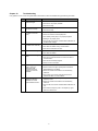
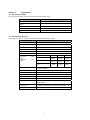
Chapter 10 Troubleshooting If any problem or error occurs during DeviceNet communication, follow the troubleshooting procedures given below. No Phenomenon/Symptom Probable Causes 1 None of the LEDs on the Card would light. The inverter is not powered ON. The Card is not properly installed. The Card is faulty. 2 3 er4 alarm cannot be reset (MS LED is lit in red). The Card is not properly installed. NS LED is lit in red. (er5 alarm cannot be reset.) There is a duplicated node address. The Card is faulty. There is a mismatch in baud (data) rate. The network power (24V) is not properly supplied. Cabling is not properly done. The inverter has not been restarted after modification of the DIP switch settings. 4 NS LED is blinking in red. (er5 alarm has occurred.) The master has a problem. The cable was broken during communication. The I/O scan interval is too short. 5 NS LED would not light. The master has a problem. The cable was broken. 6 NS LED would not light in green. The master has a problem. The I/O scan interval was set too short at the start of communication. The I/O area is invalidly mapped. There is no I/O connection. 7 Even though NS LED lights in green, the settings for RUN command or Speed Reference cannot be validated. Neither NetCtrl nor NetRef is set to “1.” On the inverter, the higher-priority RUN command or Speed Reference is enabled. There is a mistake in the selection of I/O Assembly Instances. The inverter has not been powered OFF and then powered ON after o31 was modified. 8 Although the Speed Reference has been validated, the actual speed is different from it. The number of motor poles specified by P01 does not match the motor. There is a mistake in the selection of I/O Assembly Instances. The inverter has not been restarted after modification of o31. The maximum frequency F03 or the frequency upper limit F15 is set too low. 19