1
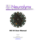
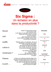
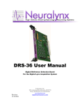
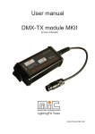
Digital Lynx User Manual Document Revision 1.41 Last Revised: June 2, 2009 Neuralynx, Inc. 105 Commercial Drive, Bozeman, MT 59715 Phone 406.585.4542 • Fax 406.585.9034 www.Neuralynx.com [email protected] Table of Contents 1 2 3 Document Overview ................................................................................................... 4 Digital Lynx Overview ............................................................................................... 7 Digital Lynx Components ........................................................................................... 8 3.1 Front Panel ........................................................................................................... 8 3.2 Rear Panel ............................................................................................................ 9 3.3 Inside the Rear Panel of the Digital Lynx interface box. ................................... 15 3.3.1 Configuring the number of Input Boards in the system. ............................. 16 4 DC Coupled Input Board Details .............................................................................. 19 4.1.1 Input Connectors ......................................................................................... 21 4.1.2 50 Pin 3M MDR Tether Extension Cable Connector ................................. 21 4.1.3 37 Pin uDB37 Tether Connector................................................................. 22 4.1.4 80 Pin 3M Connector .................................................................................. 22 4.1.5 Why have three input connectors on the front panel?................................. 24 4.1.6 Reference selection jumpers and Resistor Pack usage information............ 25 4.1.7 Input Load Resistor Packs .......................................................................... 25 4.1.8 Reference Selection Jumper Header Pin area ............................................. 26 4.1.9 Reference Bus Shorting Jumper Usage Details .......................................... 27 4.2 Input Board Differential Input Amplifiers and 24 bit A/D converters ............... 29 4.2.1 Input Board Front Panel LEDs ................................................................... 29 4.2.2 AC Coupled Input Board Details ................................................................ 30 4.3 DC Coupling Channel Modification .................................................................. 30 5 Control Board Details ............................................................................................... 32 6 Installation of the Digital Lynx System .................................................................... 34 6.1 Installation of the Digital Lynx with ERP-27 patch panels: .............................. 34 6.1.1 Installation with the DRS-36 (Digital Reference Selector-36) ................... 35 6.1.2 Digital Lynx Interface Box 15 Volt power supply. .................................... 35 6.1.3 Power the Digital Lynx Cabinet ................................................................. 36 6.1.4 Connect Fiber Optic Cable between the PC and the Interface Box. ........... 36 6.1.5 Test signal inputs with the Input Test Cable;.............................................. 37 List of Figures and Tables Figure 3-1 Front Panel of Digital Lynx .............................................................................. 8 Figure 3-2 Rear Connections of Digital Lynx .................................................................... 9 Figure 3-3 Fiber Optics Connection ................................................................................. 10 Figure 3-4 Fiber Optics Cable and PS .............................................................................. 10 Figure 3-6 Power Supply Connection ............................................................................... 11 Figure 3-5 Power Supply .................................................................................................. 11 Figure 3-7 Fiber Optics Connector ................................................................................... 12 Figure 3-8 Fiber Optics "Release" Latch .......................................................................... 13 Figure 3-9 Fiber Optics Dust Covers ................................................................................ 13 Figure 3-10 Storage of Fiber Optics Protection Equipment ............................................. 14 Figure 3-11 Fiber Optics input to EDT Card and DL ....................................................... 14 Figure 3-12 Inside the Back of the DL ............................................................................. 15 Figure 3-13 Blue Jumper Diagrams .................................................................................. 17 Figure 4-1 DC Coupled Input Board ................................................................................ 19 Neuralynx, Inc. Digital Lynx User Manual Rev 1.41 Last Revised: June 2, 2009 Page 2 Figure 4-2 MDR 50 Connector ......................................................................................... 21 Figure 4-3 uDB37 Input connector ................................................................................... 22 Figure 4-4 80 pin 3M Connector Cable Pinout ................................................................. 23 Figure 4-5 40 Pin Dual Row Connector ........................................................................... 23 4-6 Schematic of the 3-pin Reference Jumpers for Input Reference Selection ................ 28 Figure 4-7 AC Coupling Caps .......................................................................................... 31 Figure 5-1 Control Board Input Connector ....................................................................... 33 Figure 6-1 Digital Lynx in a 19” equipment rack. ............................................................ 34 Figure 6-2 DRS ................................................................................................................. 35 Figure 6-3 Input Test Cable .............................................................................................. 38 Table 1 Red MotherBoard DIP Selection ......................................................................... 18 Neuralynx, Inc. Digital Lynx User Manual Rev 1.41 Last Revised: June 2, 2009 Page 3 1 Document Overview This document is a user’s manual for the Digital Lynx data acquisition interface box. This manual is organized as: an overview of the Digital Lynx; specific information you need to know before installation (such as fiber optic cables); step by step installation instructions of the system; detailed information about hardware settings and reconfiguration; detailed information about connectors; detailed information about the Input Boards’ reference selection; detailed information about specifications, analog signals, sampling, etc. The following Symbols appear on the system components and documentation. Symbol Description Alternating Current Direct current Protective earth ground Earth (ground) Connection point for the neutral conductor on PERMANENTLY INSTALLED EQUIPMENT IPX0 Protection rating against ingress of water Attention, consult ACCOMPANYING DOCUMENTS Off (power disconnection from the mains) On (power connection to the mains) TYPE BF EQUIPMENT Neuralynx, Inc. Digital Lynx User Manual Rev 1.41 Last Revised: June 2, 2009 Page 4 240 Volt Input Voltage Range Input Current Frequency Temperature Range Relative Humidity Range Atmospheric Pressure Range 110 Volt Input Voltage Range Input Current Frequency Temperature Range Relative Humidity Range Atmospheric Pressure Range 200->240 VAC 3.2 Amp Max 50 Hz -40 Degrees C -> +70 Degrees C 10% to 100% 500 to 1060 hPa 100->125 VAC 5.2 Amp Max 60Hz -40 Degrees C -> +70 Degrees C 10% to 100% 500 to 1060 hPa Equipment not suitable for use in the presence of a flammable anesthetic mixture with air or with oxygen or nitrous oxide. The power cord is to be used for mains disconnection. Type of protection against electric shock: Class 1 Equipment Neuralynx, Inc. Digital Lynx User Manual Rev 1.41 Last Revised: June 2, 2009 Page 5 Degree of Protection against electric shock: Type BF Applied Parts Degree of Protection of the ingress of water: IPX0 Cleaning and disinfection methods: outside surfaces may be cleaned with a damp cloth and ammonia based cleaner. No user replaceable parts on the isolation cart. Neuralynx, Inc. Digital Lynx User Manual Rev 1.41 Last Revised: June 2, 2009 Page 6 2 Digital Lynx Overview Digital Lynx is a high performance data acquisition subsystem designed for neurobiology electrophysiology recording. The main features of the Digital Lynx system include: High speed 1.25 Gigabit per second fiber optic data link to the host Cheetah PC; Up to 320 Analog inputs per system; Each Analog input is sampled with an individual 24 bit A/D converter; Analog input bandwidth is DC to 8 KHz; Analog inputs are sampled at 32,556 Hz per channel; Analog inputs are simultaneously sampled; Analog input range is +/- 132 millivolts – 1 microvolt per bit at bit #18; Analog inputs are fully differential inputs; Extremely low input noise levels of 4uv peak (1.3 uv RMS) makes for better recordings; Compatible with all Neuralynx EEG/Reference Panels Direct headstage tether and Tether Extension cable inputs Headstage power supplies for tether input connectors if not using an ERP 16 bit TTL & LVTTL compatible Parallel Input Port for monitoring external signals; and Totally electrically isolated system (from AC Power and Ground) through the use of the fiber optic data link. External Timestamp Clock input and output connectors for multiple system synchronization. The Digital Lynx system can be totally isolated from Ground and AC power thru the use of the Fiber Optic Cable data transmission to the host PC running the Cheetah data acquisition software. This allows the user to control grounding if a particular power/ground noise situation exists. The electrical isolation makes it safer for the subject as this allows the subject to be ungrounded, making for a safe condition even if the patient’s body is connected to 120/240 VAC power. The only current flow would be due to capacitive coupling from the case to ground. Please note: Early versions of this product allowed the use of LiPO batteries. These batteries are not recommended for use and should be returned to the Neuralynx factory as these are not safety approved. Neuralynx, Inc. Digital Lynx User Manual Rev 1.41 Last Revised: June 2, 2009 Page 7 3 Digital Lynx Components 3.1 Front Panel Figure 3-1 Front Panel of Digital Lynx The front panel is made up of several removable modules (or blank covers for optional un-configured components). From Left to Right the modules are: 5 Input Boards and 5 DRS-36 board each support 32 Analog input channels The Control Board with the main Power Switch, Power Supply Voltage LED indicators, external 1microsecond Time Stamp input and output SMA connectors, and 16 bit TTL input port; If a module needs to be removed from the interface box the following procedure is used: 1) unscrew the two screws (one on the top side of the upper extraction handle and one on the bottom side of the lower extraction latch. These screws are “captive” to the extraction latch; i.e., the screw will not fall out; 2) press the white “release button” on both the top and bottom extraction latches; and 3) the extraction latches are spread up and down from the front of the module/cabinet to cause the board to be extracted from the backplane. Neuralynx, Inc. Digital Lynx User Manual Rev 1.41 Last Revised: June 2, 2009 Page 8 You do not need to retighten the extraction latch screws if the board is reinserted, for example in the case of the Input Board, but the screws MUST be screwed in and lightly tightened if the Digital Lynx box is shipped. 3.2 Rear Panel There are 4 external connections that can be made on the rear panel and are: 1) Ground; 2) Main 15v 4Amp power connection; 3) Obsolete Battery charging current connection; and 4) the Fiber Optic Cable connection. Figure 3-2 Rear Connections of Digital Lynx The Ground connection accepts either a standard Banana Plug or (by unscrewing the knurled cover) a wire. This ground connection should be used if a strong noise source is present and is reduced by grounding the cabinet. Under normal situations this use of this ground connection is not needed. The Obsolete Battery Charging Current connector is the same standard 2.1 mm connector as the main power. If an isolated configuration is used the batteries must be removed for charging as connecting the Charger battery charger to the box will cause the interface box to not be isolated. We will not cover the Battery Charging power connection at this point because as of 9/21/2004 charging of the batteries IN THE CHASSIS is not recommended. Neuralynx, Inc. Digital Lynx User Manual Rev 1.41 Last Revised: June 2, 2009 Page 9 Use of the Batteries is not recommended and should be returned to Neuralynx for credit return. Figure 3-3 Fiber Optics Connection The fiber optic connection is in the upper left corner of the interface box. This is a standard SC type connector. The link is bi-directional, meaning that there are two fibers in the cable for transmitting data and commands between the Digital Lynx and the computer. The Fiber Optic Cable is a standard SC type fiber optic cable. It is used for the main data communications between the Digital Lynx interface and the Computer. The Power Supply is a standard 15v 4 amp DC power supply as shown below. Figure 3-4 Fiber Optics Cable and PS Neuralynx, Inc. Digital Lynx User Manual Rev 1.41 Last Revised: June 2, 2009 Page 10 The power supply has a “Universal Input” AC Power input, which means that the input voltage range is 100 to 240 VAC and should be usable throughout the world. The AC input is a standard “3 pin DIN” connector and users should not find a problem using standard power cords from their specific country. The Main 15v power connection is a standard 2.1 mm (or 2.5mm) power plug receptacle. The external power supply module supplied with the Digital Lynx is rated for 4 amps, but Digital Lynx does not consume the full 60 watts. Note: Be careful not to insert the main power supply module into the Battery Charging connector. It will not damage any components but the system will not “power up”. Figure 3-5 Power Supply Figure 3-6 Power Supply Connection The Fiber Optic connection is a standard SC type fiber optic connection. A standard fiber optic cable is supplied (in 3meter and/or 10 meter lengths) to make the connection from the Digital Lynx to the host PC. Neuralynx, Inc. Digital Lynx User Manual Rev 1.41 Last Revised: June 2, 2009 Page 11 Figure 3-7 Fiber Optics Connector The SC connectors have a positive latch which makes a “click” sound when engaged. There is a small clear “ramp” release tab that is squeezed to release the positive latch. Be gentle with the fiber optic cable as the exposed ends of the cable are polished for proper light transfer and must not be touched, scratched or hit. Also, the fiber cable should not be bent in a sharp bend; a 4 inch diameter (10 cm) radius should be maintained when routing the cable from the Digital Lynx box to the PC. To release the fiber optic cable the clear plastic Release Ramp is gently depressed as shown below. Neuralynx, Inc. Digital Lynx User Manual Rev 1.41 Last Revised: June 2, 2009 Page 12 Figure 3-8 Fiber Optics "Release" Latch Before inserting the Fiber Optic cable the Dust Caps (one for each individual fiber) must be removed as shown below. These dust caps MUST be saved to protect the fiber ends when the cable is disconnected from the system. Figure 3-9 Fiber Optics Dust Covers Also note that there are small black soft rubber “dust covers” that are inserted into each of the fiber optic connections/sockets on the back of the computer and Digital Lynx. These black dust covers must be removed before the fiber can be connected. These dust covers must be saved and should be placed back into the fiber optic transceiver receptacle when the fiber cable is disconnected for an extended period. See below for more information about proper care of fiber optic components. Neuralynx, Inc. Digital Lynx User Manual Rev 1.41 Last Revised: June 2, 2009 Page 13 Dust Cover on PC Dust Cover on the Digital Lynx Removal of the dust cover After removal of the dust caps and socket dust plugs store these 6 items in the plastic bag which contained the fiber optic cable. Figure 3-10 Storage of Fiber Optics Protection Equipment Connect the fiber optic cable between the computer and Digital Lynx Box. Be cautious to not make a sharp bend in the cable as this will break the plastic optical fiber and will cause data transmission errors. Note for the PC and Digital Lynx connections the plastic release latches will be facing downward. Do not force the fiber optic connections. You will hear the latches “click” into place when the connection is properly made. Figure 3-11 Fiber Optics input to EDT Card and DL Note: The rear panel of the Digital Lynx box can be opened, (hinged on the bottom) therefore make sure that the fiber cable’s clear plastic latch does not catch on the edge of Neuralynx, Inc. Digital Lynx User Manual Rev 1.41 Last Revised: June 2, 2009 Page 14 the panel hole for the fiber connector. This will allow the rear panel to be opened and closed while the fiber is connected. 3.3 Inside the Rear Panel of the Digital Lynx interface box. Figure 3-12 Inside the Back of the DL The rear panel is hinged for user access. The only user-removable components are the Xilinx Compact Flash Card (plugged into the Xilinx System ACE board) and the Infinion Fiber Optic Cable driver module, which normally will not give any problems. The rear panel is opened by unscrewing the top 3 screws. If the fiber optic cable is still attached the panel may be opened but pay extra care not to damage the cable. Disconnect the 15 volt power supply cable to avoid damage to the power cable. The main components on the inside of the rear section of the interface box consist of: The Xilinx/Insight Development Board, called the “Motherboard” which controls all data transfer of A/D data from the input boards and fiber optic data packet communications to the host PC. This board has a red 8 position Configuration Neuralynx, Inc. Digital Lynx User Manual Rev 1.41 Last Revised: June 2, 2009 Page 15 DIP switch which tells the Motherboard the number of Input Boards installed in the system; The Xilinx System ACE module and Compact Flash Memory card which is plugged into the Xilinx/Insight Development board, note that this card reads data in the Compact Flash card and programs all of the Xilinx programmable logic devices in the Digital Lynx). It is plugged into the Motherboard and is perpendicular to the Motherboard; The Infinion Fiber Optic Transceiver PC board has four high speed SMA coax cables that connect to the Motherboard. This board also has 2 small LEDs, a GREEN LED to show power and a RED LED which when lit indicates that the fiber optic cable does not have an optical signal from the PC (it will normally be off); The back plane PC board with power supply modules and fuse (and front side bus connectors to all of the plug in modules). The gray ribbon Data Cables connect the Motherboard to the back plane data bus. The cables’ connectors are not securely locked into place and may come loose in shipping. If these are loose the system will not transfer data from the A/D inputs to the motherboard. There are 2 cables, each cable consists of two 40 conductor ribbon cables. The Bulk Power Supplies convert the +15v from the main power supply or the batteries into +3.5v, -5.5v and +5.5v which is distributed to the Control Board and the Input Boards. For a full 10 Input Board system the power supply heat sinks may be very warm to the touch. Xilinx WH-PCIV Programming Cable/Module is a temporary method for programming the first couple of systems installed before Sept 22, 2004. After this date this cable is not needed as the system will be booted/programmed by data in a Compact Flash Memory Card that is inserted into the Xilinx System ACE board. If this cable is present in your system please remove it and return it to Neuralynx as this cable will not be used in the future. The bug in the Xilinx software is now solved. A compact flash card is now programmed and inserted into the System Ace PC board. The system will automatically boot and program all the Xilinx devices when power is turned on. Contact Neuralynx for a new Compact Flash memory card if you are still using the Xilinx HW-PC-4 cable. 3.3.1 Configuring the number of Input Boards in the system. There are two operation modes that are dependent on the number of Boards in the system. The first is during the boot-up/programming state that occurs right after the system is powered up. This operation uses a “JTAG” Serial Bus which is daisy chained from the first Input Board thru the last board in the backplane and then to the Motherboard (the Xilinx Development Board mentioned above). The programming must have the proper software loaded on the Flash RAM card and the “blue jumper wire” must be set to the Neuralynx, Inc. Digital Lynx User Manual Rev 1.41 Last Revised: June 2, 2009 Page 16 proper connection for the number of boards in the system as this connects the JTAG serial bus string from the last board in the buss back to the Motherboard. This single stranded blue wire will be placed on the 20 pin connector pins for the TDO signal as shown below in the following two diagrams. Number of Boards 1 2 3 4 5 6 7 8 9 10 Blue Wire Pin # 15 14 13 12 11 10 9 8 7 6 Figure 3-13 Blue Jumper Diagrams Neuralynx, Inc. Digital Lynx User Manual Rev 1.41 Last Revised: June 2, 2009 Page 17 The second operation that is dependent on the number of boards in the system is when the system is running and data is being transferred from the Input Boards to the Motherboard over the backplane. The Motherboard Xilinx logic needs to know the number of boards in the system which also determines the size of the data packet transferred to the PC. The number of boards is set on the RED Dip-Switch on the Motherboard as in the following table. Table 1 Red MotherBoard DIP Selection Board Sw1 Configuration I ID IDID ID x 3 ID x 4 ID x 5 II Ix4 Ix5 Ix6 Ix7 Ix8 Ix9 I x 10 Up Up Up Up Up Down Up Up Up Up Up Up Down Down Sw2 Sw3 Sw4 Sw5 Sw6 Sw7 Sw8 Up Up Up Down Down Up Up Up Down Down Down Down Up Up Up Up Down Up Down Up Up Down Up Up Down Down Up Up Up Up Up Up Up Up Down Down Up Down Up Down Up Down Up Up Up Up Up Up Up Up Up Up Up Up Up Up Up Up Up Up Up Up Up Up Up Up Up Up Up Up Up Up Up Up Up Up Up Up Up Up Up Up Up Up Up Up Up Up Up Up Up Up Up Up Up Up Up Up Neuralynx, Inc. Digital Lynx User Manual Rev 1.41 Last Revised: June 2, 2009 Page 18 4 DC Coupled Input Board Details Figure 4-1 DC Coupled Input Board The input boards have three major sections: The Input connectors, input load Resistor Pack Sockets, and Reference Selection Jumper Pins; The 32 Differential Input Amplifiers and 24 bit A/D converters; and The Xilinx FPGA digital programmable logic chip, 3 digital level converter I.C.s and backplane bus interface connector. Neuralynx, Inc. Digital Lynx User Manual Rev 1.41 Last Revised: June 2, 2009 Page 19 Input Board Front Panel +5v Headstage Power Okay -5v Headstage Power Okay +5v Analog Power Okay – for Input Amps and A/D Chips -5v Analog Power Okay – for Input Amps and A/D Chips 50 Pin 3M MDR Connector for the Neuralynx Tether Extension Cables Blue LED – Headstage Power +/-5v ON to Headstage Connectors 37 Pin uDB37 Tether Connector – Standard for Neuralynx HS-27 80 Pin 3M Connector. This connector is arranged to be compatible with a single ERP-xx patch panel connector. This connector support the full 32 channel differential input connections. It is arranged as 4 sections of 20 pins, each section has 16 signals for 8 differential input channels and 4 ground pins. LPOK - Green LED showing the presence of Digital Logic Power LED1 - Green LED used to show status from the Digital Logic LED2 - Green LED used to show status from the Digital Logic LED3 - Green LED used to show status from the Digital Logic LED4 - Green LED used to show status from the Digital Logic Neuralynx, Inc. Digital Lynx User Manual Rev 1.41 Last Revised: June 2, 2009 Page 20 4.1.1 Input Connectors The 3 Input Connectors on the front panel provide compatible connections to existing Neuralynx Headstages, Tethers, Tether Extension Cables; and Neuralynx ERP-xx patch panels. These 3 input connectors are: The 3M 50 pin MDR Tether Extension Cable connector; The 37 pin uDB37 Tether cable connector; and a new connector The 80 Pin 3M Latching connector which provides differential inputs to all 32 channels. This connector is arranged in 4 groups of 8 input channels and a ERPInput cable is used to connect the output of the Neuralynx ERP-XX patch panels to the input board. 4.1.2 50 Pin 3M MDR Tether Extension Cable Connector The 3M 50 pin MDR connector has the same pinout and functionality as the input connector on the Neuralynx ERP-27, ERP-54 and Warp-144 EEG/Reference Patch Panels. Note: eight unused pins on this connector are now used for the eight extra input channels (In+24 thru In+31) on the Input Board. This is because the ERPs only supported 24 channels plus the reference channels (Ref, EE1 & EE2) but the Digital Lynx Input Board supports 32 input channels per board. Figure 4-2 MDR 50 Connector Neuralynx, Inc. Digital Lynx User Manual Rev 1.41 Last Revised: June 2, 2009 Page 21 4.1.3 37 Pin uDB37 Tether Connector The 37 pin connector has the same pinout and functionality as the standard Neuralynx HS-27 and HS-54 Headstage amplifiers. Figure 4-3 uDB37 Input connector 4.1.4 80 Pin 3M Connector The 80 pin 3M connector provides a connection to all existing ERP patch panels. This connector has been “pined-out” so that a single connector (with two 40 pin ribbon cables) has the same pinout as 4 Lynx-8 Amplifier input connectors. A cable harness is provided to connect the proper number of Input Boards to the same number of ERP-27s patch panels. Each of these cables (pairs of 40 pin ribbon cables) is terminated to four 20 pin ribbon cable connectors which may be plugged into the rear ERP-27 panel JampX connectors. Neuralynx, Inc. Digital Lynx User Manual Rev 1.41 Last Revised: June 2, 2009 Page 22 Figure 4-4 80 pin 3M Connector Cable Pinout The 80 pin cable connector is shown below. Note that the red edge of each ribbon cable corresponds to Pin 1 and Pin 41 of the 80 pin connector as shown in the picture. Figure 4-5 40 Pin Dual Row Connector Neuralynx, Inc. Digital Lynx User Manual Rev 1.41 Last Revised: June 2, 2009 Page 23 4.1.5 Why have three input connectors on the front panel? An obvious question that a user should ask at this point is “Why are there so many input connectors on the Input Board?”. The answer is that we wanted to make the system as flexible as possible to support various combinations of ERPs usage and also direct headstage/tether connections for using the system without ERPs. The ERPs have shown to be the best/fastest solution for extra/intra cranial noise reduction thru the use of the reference selection controls. ERPs are relatively large to the size of the Digital Lynx box when you consider a full configuration of 10 Input Boards and 10 ERP-27s. Therefore we decided to support direct tether/headstage connections. The Input Boards supports a limited but the same type of reference selection facilities as the ERPs. Input Board reference selection is made with small “shorting pin jumpers” which are only accessible when the Input Board is removed from the system. This is a “size versus convenience” trade-off. For most laboratory environments users will choose to use the ERP panels. The next section describes the Input Board setup for using the direct tether/headstage connections. Neuralynx, Inc. Digital Lynx User Manual Rev 1.41 Last Revised: June 2, 2009 Page 24 4.1.6 Reference selection jumpers and Resistor Pack usage information If you are using either the 50 pin 3M MDR or the 37 pin uDB37 connectors you will have to use the “Reference Selection Jumper Pins” and three 10Kohm Resistor Packs on the DC input board and 4 on the AC coupled input board. All of the 10Kohm Resistor packs should be aligned so that the writing on them is facing the faceplate of the input board. These two input connectors only provide Signal connections (positive inputs) to each input channel and do not assign/connect any signals to each channel’s Reference Signal (minus input). The connections to the Reference (minus inputs) is done with the “Shorting Jumpers”. The use of the Reference Selection Jumper Pins will be described below. If the ERP patch panels are used in the system the functions of Reference Selection is provided by the ERP. The 80 pin connector is used for ERP connection as this provides the Signal and Reference inputs for all 32 channels. In this situation all of the “shorting jumpers” should be removed. The 10Kohm Resistor Packs should also be removed because these same Resistor Packs are present on the ERP panels/DRS boards. Note that the shorting jumpers and resistor packs have been properly configured (installed or removed) to match the total configuration of your system at the time that your complete system was shipped from Neuralynx; regardless, you should check for proper configuration of these parts. Please refer to the annotated Input Board picture above for the locations of parts. 4.1.7 Input Load Resistor Packs There are three 16 pin sockets in back of the input connectors. These are for 10Kohm resistor packs (15 resistors in a DIP package) which provide a lower impedance load at the inputs to eliminate large noise signals if the input connectors are disconnected and to reduce high frequency noise. These resistor packs are the same as used on the ERP-27 patch panels and serve the same function. These Resistor Packs will be installed in these sockets if the ERP-xx patch panel(s) are NOT used with the Input Board. When these 3 Resistor Packs are installed, a 10Kohm resistor is connected from each of the 32 input channels’ Signal (positive inputs) to ground. There are also 3 jumper pin pairs that allow connection of the Ref, EE1 and EE2 signals to be connected to one of the 10Kohm resistors. There are no 10Kohm resistor connections to the Reference Inputs for each channel in the Resistor Packs. Neuralynx, Inc. Digital Lynx User Manual Rev 1.41 Last Revised: June 2, 2009 Page 25 4.1.8 Reference Selection Jumper Header Pin area Neuralynx, Inc. Digital Lynx User Manual Rev 1.41 Last Revised: June 2, 2009 Page 26 4.1.9 Reference Bus Shorting Jumper Usage Details The Digital Lynx Input Boards contain a subset of the Neuralynx ERP-27 EEG/PatchPanel functionality. There are a total of two Reference Buses (to select individual A/D input references from for each channel) which may be driven by two of the five HS-27 standard references Ref, EE1, EE2, AGnd and PGnd. (See the Neuralynx ERP-27 Manual for reference selection strategy and operation of the ERP-27 panel.) Like the ERP-27, the Input Board also contains 10 Kohm resistor packs for headstage signal line loading to reduce high frequency noise and keep noise signals to a minimum when the headstage is either powered off or disconnected. These resistor packs have sockets on the input boards. On each input board (both AC and DC coupled inputs) there are many .025" square "jumper posts" used for: 1) input channel reference selection; and 2) resistor pack signal line loading of the Headstage reference signal lines. These .025" square posts (spaced at 2.54 mm) are also referred to as "shorting posts" and are commonly used on PC Boards and other electronics as "configuration jumpers". The idea is that a small "shorting jumper" (plastic body with a small conductive metal strip inside) is placed over two adjacent gold pins, making a connection similar to a switch. There are two configuration of .025" post, one with two posts (to make a Single Pole Single Throw "common" switch) and the other is with 3 posts, where the center post is the "signal" and the two adjacent posts are the "selections"; the center post can be connected to either of the outside (adjacent) posts (to make a Single Pole Double Throw switch). There are a total of: six 2-pin posts for reference signal connections; five 3-pin posts used to select Reference Signals (Ref, EE1, EE2, AGnd and PGnd) to the two Reference Buses (Ref1 and Ref2); and 32 individual channel Ref1/Ref2 reference bus connections. Three of the six 2-pin jumper positions which are used to connect resistor pack load resistors (10 Kohms) on the reference lines (3 total). The other three 2-pin jumper posts are used to connect the three references (Ref, EE1 & EE2) to A/D input channels 24, 25 and 26. (This last function was to allow HS-27 users to directly record the reference signals by connecting them to unused A/D channels.) The Five Reference Signals Commonly Used The HS-27 has three signals, Ref, EE1 and EE2 which are normally used as reference inputs but may be used for any purpose as these signals are buffered the same as the normal 24 electrodes. The AGnd (Animal Ground) is usually connected directly to the Headstage ground plane and can be used as a reference. The PGnd (Panel Ground) is Neuralynx, Inc. Digital Lynx User Manual Rev 1.41 Last Revised: June 2, 2009 Page 27 connected to the ground plane of the Input Board and may be used as a reference. The following schematic shows the connections to the 3-pin posts and the reference Ref1 and Ref2 buses. 4-6 Schematic of the 3-pin Reference Jumpers for Input Reference Selection Note that schematics use the concept of “Net Names” for signal connections that are physically connected together. For example RefSel1 creates a bus which connects the selection of the 5 reference source signals to all of the Input Channels’ reference selection pin for RefSel1 bus (In-0 thru In-31). The group of five 3-pin connectors allows the connection of the five reference signals to the two Reference bus lines. To connect a reference signal to Ref1 place a jumper on the middle and bottom pins for the reference signal. To connect a reference signal to Ref2 place a jumper on the middle and top pins for the reference signal. Note that only 1 reference source signal (from the headstage) should be connected to the Ref1 bus line and only one reference source signal should be connected to the Ref2 bus line. For the thirty two 3-pin jumper area, each of the 32 input channels for the board has one 3-pin connector. As in the reference source selection area, connections for an input channel to the Ref1 or Ref2 bus lines is made by inserting the shorting jumper to either the bottom or top and middle pins. Any or all 32 channel reference jumpers can be connected to either the Ref1 or Ref2 bus lines. Neuralynx, Inc. Digital Lynx User Manual Rev 1.41 Last Revised: June 2, 2009 Page 28 4.2 Input Board Differential Input Amplifiers and 24 bit A/D converters Each input channel consists of a Differential Input – Differential Output amplifier with a gain of about 15. The differential output of this amplifier is connected to the input of a 24 bit A/D converter. There is also a 9KHz single pole anti-aliasing filter between the amplifier and the A/D converter. The A/D converter is typically run at 32 Khz (32,556 Hz is the exact sampling frequency). The input amp gain of 15 makes the signal amplitude, along with the input range and resolution of the A/D converter, such that the 18th bit of the A/D converter represents 1 microvolt. This gives an input signal range of the input versus the input reference (the differential input range) to be +/- 132 millivolts. The output of the A/D converter is stored on the Input Board and then immediately read by the Xilinx device on the Motherboard located on the rear of the Backplane (see above). All channels on all boards are sampled simultaneously. 4.2.1 Input Board Front Panel LEDs There are 10 Front Panel LEDs which show status of the Input Board. Note that these LEDs have been set back from the front panel viewing holes to reduce the amount of light and possible distraction therefore the viewing angle is very limited. The LEDs from top to bottom are: HS +5v Power – this indicates that the Headstage Power Supply has +5v voltage and is ready. HS – 5v Power – this indicates that the Headstage Power Supply has –5v voltage and is ready. +5V Analog – this indicates that the Analog Circuitry power supply for the input instrumentation amplifiers and the 24 bit A/D converters has +5v voltage and is ready. -5V Analog – this indicates that the Analog Circuitry power supply for the input instrumentation amplifiers has -5v voltage and is ready. HS OK – This is a Blue LED and it indicates that power is present to the headstage/tether 3MMDR and uDB37 connectors. Note that the HS Power is turned on the first time that acquisition is started and it is left on until the interface is powered off. LP OK – this indicates that the +3.5v Digital Circuitry power supply is on and is supplying power to the Digital logic on the Input Board. LED1 thru LED4 – These are general leds connected to the Xilinx programmable logic integrated circuit. These are used to show a “heart-beat” of the logic that has been programmed into the Xilinx device. These LEDs are currently connected to a counter in the logic. These should blink at a rate around once per second. All Input Boards should flash these LEDs at the same rate and synchronously. Neuralynx, Inc. Digital Lynx User Manual Rev 1.41 Last Revised: June 2, 2009 Page 29 4.2.2 AC Coupled Input Board Details The AC Coupled Input board is identical to the DC Coupled Input Board described above with the following exceptions: The micro-DB 37 connector was removed, AC Coupling Capacitors for .16Hz High Pass Filtering were added (2 per channel); A Common Mode Rejection Ratio Adjustment Potentiometer was added; The Headstage 10K ohm Load Resistor Packs were changed to SIP packages. 4.3 DC Coupling Channel Modification The AC Coupling Capacitors may be disabled easily on a per channel basis if required. This is a fairly easy process, but once performed a channel cannot be converted back to AC Coupling because of the change in value of the AC input capacitors during the soldering process. Details for the modification Note:, Rosin Core Solder should be used. Do NOT use water soluble flux solder as this type of flux must be cleaned off of the PC board due to its caustic nature. The process is fairly simple: first locate the pair of capacitors for the channel that you want to convert to DC coupling; and second, solder a small wire across the top of each of the capacitors to disable the AC coupling. The AC Coupling Capacitors are part names CExx and CFxx where xx is the channel number from 0 thru 31. The capacitors are shown in the red highlighted area. Also note that the channels are numbered from right to left as: 16, 0, 17, 1, 18, 2, etc, so that the right most two Neuralynx, Inc. Digital Lynx User Manual Rev 1.41 Last Revised: June 2, 2009 Page 30 capacitors are for channel 16. Also note that the Channel Numbers are shown below the AC coupling circuit in the larger white lettering. Figure 4-7 AC Coupling Caps Picture showing the AC Coupling Capacitors for the high numbered channels on the left side of the PC board. The capacitors are shown in the red highlighted area. Note that the channels numbering is continued from the above picture and that the left most channel is 15 and channel 31 is to the right of that. Also note that the Channel Numbers (15, 31, 14, 30, 13, 29, etc) are shown below the AC coupling circuit in the larger white lettering. Make sure that you are jumping the shorting wire across the larger capacitor (3mm by 1mm taller device) and NOT the much smaller surface mount resistors (RHxx and RGxx) which are located between the AC coupling capacitors and the channel number lettering. Neuralynx, Inc. Digital Lynx User Manual Rev 1.41 Last Revised: June 2, 2009 Page 31 5 Control Board Details The Control Board contains the main power switch and power supply LED indicators, the main Time Stamp Clock external input and a buffered square wave External Output coax jacks (these are SMA type connectors), and the 16 bit Digital TTL Parallel Input port connector (34 pin ribbon cable IDC connector). The 1 microsecond TimeStamp clock signal is always present on the TS Clock Output SMA Connector when the interface box is configured. This clock signal will have a voltage from 0v (clock low) to 2.5v (clock high). The External TimeStamp Clock Input SMA connector is used when synchronizing multiple Digital Lynx systems or other acquisition systems requiring a clock. The 16 bit parallel Digital Input port is an input only port. This is present on the 34 pin connector and has the standard pin out compatible with the other Neuralynx data acquisition system. In this standard all of the even pins are ground, the odd pins 1->31 are input bits 0->15 respectively and pin 33 is also ground. The orientation of the pin numbering is shown in the following figure. The Logic Levels on the Digital Input port connector are defined as LVTTL/LVCMOS which range between 0 (low) and +2.5v (high). A voltage level up to +5.0v may be input to this port without damage. Make sure the input voltages do not go below ground. Neuralynx, Inc. Digital Lynx User Manual Rev 1.41 Last Revised: June 2, 2009 Page 32 Figure 5-1 Control Board Input Connector Neuralynx, Inc. Digital Lynx User Manual Rev 1.41 Last Revised: June 2, 2009 Page 33 6 Installation of the Digital Lynx System The installation of the Digital Lynx System consists of: 1. Mount the Digital Lynx Cabinet and ERP patch panels if applicable; 2. Connect the Power Supply and Power Up Test; 3. Connect the Fiber Optic Cable to the Computer; 4. Test signal inputs with the Input Test Cable; 5. Connect Headstages and/or Patch Panels; 6. Test with Signal Mouse input signals. The installation of your Digital Lynx system will depend on the type of Reference Patch Panel you are using; either the ERP-27 external patch panel or the DRS-36 Digital Lynx Rack Slot panel. If you purchased the DRS-36 boards they will be appropriately installed in the Digital Lynx System. 6.1 Installation of the Digital Lynx with ERP-27 patch panels: Figure 6-1 Digital Lynx in a 19” equipment rack. The cabling shipped with your Digital Lynx System has been specifically made for your system order. Your EEG/Reference/Patch Panels (ERP-27s or Warp-144 panels), power supply, and Digital Lynx Interface Box need to be arranged in the following manner. The ERP patch panels must be located above the Digital Lynx interface box and are usually located at the very top of the rack, consecutively with no space between panels. Neuralynx, Inc. Digital Lynx User Manual Rev 1.41 Last Revised: June 2, 2009 Page 34 You should have one ERP-27 for each input board. Leave 1” to 1 ¾” between the bottom of the last ERP-27 and the Digital Lynx Interface Box, this space will be used to route cables between the ERP-27s and the Digital Lynx Input Boards. The Lynx-8 Power Supply (+/- 15v power supply) should be located below the Digital Lynx Interface Box. This power supply will power only the ERP-27s, the Digital Lynx has a separate power supply or will run off of batteries. The large black ribbon cable harness is used to connect the ERP-27’s back panel amplifier connectors (JAmp1 thru JAmp4) to the Digital Lynx Input Board’s 80 pin connectors. This cable should first be held in place and connected to the Input Boards. Then each of the Dual-40 pin ribbon cables from each Input Board will connect to the JAmp1 thru JAmp4 as labeled on the individual 20 pin connectors. Note: it is easiest to start with the bottom ERP-27 connections. Next install the ERP-27 Power Cable (braided Black, Red and Green cable) from the Power Supply to the white/gold 5 pin power connectors on the back of each ERP-27. First connect the three “spade lugs” of the braided power cable to the three barrier strip screws on the rear of the Power Supply. Make special note that the three screws are labeled R, G, B which stands for Red, Green and Black respectively and indicates the three colored wire connections for the braided power supply cable. Next connect the white 5 pin cable connectors to the back of each ERP-27. It is best to start from the bottom. There may be extra unused power connectors on the cable but the overall length and placement of the used connectors should be sufficient for the number of ERP-27 panels in the system. 6.1.1 Installation with the DRS-36 (Digital Reference Selector-36) Mount the Digital Lynx Cabinet at a convenient location in your 19” standard rack. The Digital Lynx Cabinet may also be left on a desk/table top or installed in a medical equipment type cart if desired. Make sure that the “dual 40 pin ribbon cables” used to connect the DRS-36 to the Input Board are connected between the lower 80 pin connectors of the pair of boards. Without these cables you will not receive any signal. Figure 6-2 DRS 6.1.2 Digital Lynx Interface Box 15 Volt power supply. A separate power supply module (3 pin power DIN connector to a 2.1 mm power connector, center positive) has been shipped for running the Digital Lynx Interface Box. This power supply is used unless the system must be unconnected (both AC and DC Neuralynx, Inc. Digital Lynx User Manual Rev 1.41 Last Revised: June 2, 2009 Page 35 coupling) from Earth Ground and AC wall power. This would be the case if your IRB board allowed the use of the system for human patients or other noise in the environment dictated powering the system from batteries. Regardless, the power supply can be used during this initial setup and installation. This power module CUI #… is a universal input, good for 100 VAC to 240 VAC and should work throughout the world. This module will automatically detect the power voltage and will adjust for proper operation. There is no user settable selector switch. Plug the 2.1mm power plug into the far outside POWER jack on the Digital Lynx Interface Box rear panel. Plug the AC power side of the power module to AC power. The supply requires 4 seconds before turning on. The very top light on the top of the Control board should now be light, indicating that input power is present and the system may be turned on. 6.1.3 Power the Digital Lynx Cabinet Turn on the Control Board Power Switch. After a few seconds the interface box should be successfully programmed. Successful Programming Indication The 5 LEDs on the bottom of each Input Board will do a unique LED pattern when each board is programmed. The sequencing of the lights of all Input Boards should occur synchronously. The 3 LEDs that sequence are: LED1, LED3 & LED4. LP_OK and LED2 should be on continuously. 6.1.4 Connect Fiber Optic Cable between the PC and the Interface Box. The system shipment contains one or two ORANGE colored fiber optic cable. This connected between the EDT-PCDA board in the PC and the rear panel of the Digital Lynx Interface Box. The ends of this cable are the same. Connect one end to the Digital Lynx and the other end to the PC EDT-PCDA board. See the instructions in the previous text for information on connecting this fiber optic cable. Note: The fiber optic cable is fragile and must not be bent in a sharp radius; the minimum radius for these cables is about 8 cm. Neuralynx, Inc. Digital Lynx User Manual Rev 1.41 Last Revised: June 2, 2009 Page 36 6.1.5 Test signal inputs with the Input Test Cable; An Input Board Test Cable is shipped with new systems as of September 2005. This cable allows testing of inputs for signal and Common Mode Rejection (CMR) operation. This is a very simple cable. All 32 Positive input channel signal connections are connected together to the Red banana plug , all 32 input channel reference inputs are connected together to the Black banana plug, and the input grounds are connected to the Green banana plug. The three banana plugs are: Red Signals (32) Black Reference Signals (32) Green Ground (16) This is used with a signal generator that is capable of outputting signals as low as +/-132 mv peak-peak as this is the maximum signal input range of the Input Boards. There is not a 1000:1 signal reduction resistor network on the input of this cable as in other test signal sources from Neuralynx; therefore you do not need to set the generator output to 1v to get a 1 millivolt input to the board as is commonly done with the SM-27 Signal Mouse. You will need the supplied adapter to get Banana Jack connections from the signal generator. For the basic signal test connect: Red banana jack to the Signal of the generator; Black to the Ground of the generator; and Green to the Ground of the generator. Set the Signal Generator output to 1 millivolt, square wave at 20 Hz. This will put 1 millivolt spikes on the spike channels and a 1 millivolt square wave signal on the CSC channels, depending on frequency filtering settings. Adjust the SC/CSC gains so you can see an unclipped waveform on the displays. The Common Mode Rejection Test put the same signal on both the +Signal and – Reference input of each channel of the Input Board. The test is to see how well the inputs subtract the reference from the signal. CMR test connections: Red banana jack to the Signal of the generator; Black banana jack to the Signal of the generator; and Green to the Ground of the generator. Set the Generator to 5volt (or the maximum output signal of the generator if it is a Minirator) 20 Hz Sine wave. You should see a very small signal when the gain is turned up to 50,000. This test is only valid for CSC displays as spike channels will need to see a “spike” which will not occur for a 20 Hz sine wave input. Neuralynx, Inc. Digital Lynx User Manual Rev 1.41 Last Revised: June 2, 2009 Page 37 The schematic for the input test cable is shown below. Note that this shows only one of the 40 pin cables from the Input Board connector; the other 40 pin cable is connected the same way. Figure 6-3 Input Test Cable Neuralynx, Inc. Digital Lynx User Manual Rev 1.41 Last Revised: June 2, 2009 Page 38